Embed Size (px)
Citation preview
IR PC-3 (Issued 04/21/20) Page 1 of 14 DIVISION OF THE STATE ARCHITECT DEPARTMENT OF GENERAL SERVICES STATE OF CALIFORNIA
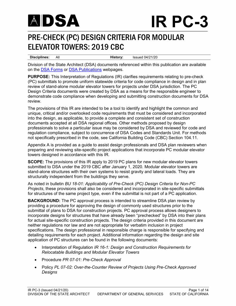
IR PC-3 PRE-CHECK (PC) DESIGN CRITERIA FOR MODULAR ELEVATOR TOWERS: 2019 CBC
Disciplines: All History: Issued 04/21/20
Division of the State Architect (DSA) documents referenced within this publication are available on the DSA Forms or DSA Publications webpages. PURPOSE: This Interpretation of Regulations (IR) clarifies requirements relating to pre-check (PC) submittals to promote uniform statewide criteria for code compliance in design and in plan review of stand-alone modular elevator towers for projects under DSA jurisdiction. The PC Design Criteria documents were created by DSA as a means for the responsible engineer to demonstrate code compliance when developing and submitting construction documents for DSA review. The provisions of this IR are intended to be a tool to identify and highlight the common and unique, critical and/or overlooked code requirements that must be considered and incorporated into the design, as applicable, to provide a complete and consistent set of construction documents accepted at all DSA regional offices. Other methods proposed by design professionals to solve a particular issue may be considered by DSA and reviewed for code and regulation compliance, subject to concurrence of DSA Codes and Standards Unit. For methods not specifically prescribed in the code, see California Building Code (CBC) Section 104.11. Appendix A is provided as a guide to assist design professionals and DSA plan reviewers when preparing and reviewing site-specific project applications that incorporate PC modular elevator towers designed in accordance with this IR. SCOPE: The provisions of this IR apply to 2019 PC plans for new modular elevator towers submitted to DSA under the 2019 CBC after January 1, 2020. Modular elevator towers are stand-alone structures with their own systems to resist gravity and lateral loads. They are structurally independent from the buildings they serve. As noted in bulletin BU 18-01: Applicability of Pre-Check (PC) Design Criteria for Non-PC Projects, these provisions shall also be considered and incorporated in site-specific submittals for structures of the same project type, even if the submittal is not part of a PC application. BACKGROUND: The PC approval process is intended to streamline DSA plan review by providing a procedure for approving the design of commonly used structures prior to the submittal of plans to DSA for construction projects. PC approval process allows designers to incorporate designs for structures that have already been “prechecked” by DSA into their plans for actual site-specific construction projects. The design criteria provided in this document are neither regulations nor law and are not appropriate for verbatim inclusion in project specifications. The design professional in responsible charge is responsible for specifying and detailing requirements for each project. Additional information regarding the design and site application of PC structures can be found in the following documents:
• Interpretation of Regulation IR 16-1: Design and Construction Requirements for Relocatable Buildings and Modular Elevator Towers
• Procedure PR 07-01: Pre-Check Approval
• Policy PL 07-02: Over-the-Counter Review of Projects Using Pre-Check Approved Designs
DSA IR PC-3 PRE-CHECK (PC) DESIGN CRITERIA FOR MODULAR ELEVATOR TOWERS: 2019 CBC
IR PC-3 (Issued 04/21/20) Page 2 of 14 DIVISION OF THE STATE ARCHITECT DEPARTMENT OF GENERAL SERVICES STATE OF CALIFORNIA
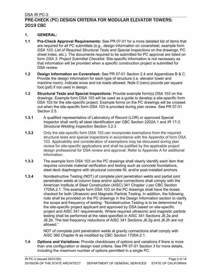
1. GENERAL: 1.1 Pre-Check Approval Requirements: See PR 07-01 for a more detailed list of items that
are required for all PC submittals (e.g., design information on coversheet, example form DSA 103: List of Required Structural Tests and Special Inspections on the drawings, PC sheet index, etc.). The documents required to be submitted for PC approval are listed on form DSA 3: Project Submittal Checklist. Site-specific information is not necessary as that information will be provided when a specific construction project is submitted for DSA review.
1.2 Design Information on Coversheet: See PR 07-01 Section 2.4 and Appendices B & C. Provide the design information for each type of structure (i.e. elevator tower and machine room). Indicate snow and ice loads allowed. Note 0 (zero) pounds per square foot (psf) if not used in design.
1.3 Structural Tests and Special Inspections: Provide example form(s) DSA 103 on the drawings. Example form DSA 103 will be used as a guide to develop a site-specific form DSA 103 for the site-specific project. Example forms on the PC drawings will be crossed out when the site-specific form DSA 103 is provided during plan review. See PR 07-01 Section 2.5.
1.3.1 A qualified representative of Laboratory of Record (LOR) or approved Special Inspector shall verify all steel identification per CBC Section 2202A.1 and IR 17-3: Structural Welding Inspection Section 3.2.3
1.3.2 Only the site-specific form DSA 103 can incorporate exemptions from the required structural tests and special inspections in accordance with the Appendix of form DSA 103. Applicability and consideration of exemptions may be discussed during plan review for site-specific applications and shall be justified by the applicable project design professional for DSA review and approval. Refer to Appendix A for additional information.
1.3.3 The example form DSA 103 on the PC drawings shall clearly identify each item that requires concrete material verification and testing such as concrete foundations, steel deck diaphragms with structural concrete fill, and/or post-installed anchors.
1.3.4 Nondestructive Testing (NDT) of complete joint penetration welds and partial joint penetration welds at column base and/or splice connections shall comply with the American Institute of Steel Construction (AISC) 341 Chapter J per CBC Section 1705A.2.1. The example form DSA 103 on the PC drawings shall have the boxes checked for both Ultrasonic and Magnetic Particle Testing. In addition, the following note shall be provided on the PC drawings in the Design Information section to clarify the scope and frequency of testing: “Nondestructive Testing is to be determined by the site-specific project applicant and approved by DSA based on site-specific project and AISC 341 requirements. Where required ultrasonic and magnetic particle testing shall be performed at the rates specified in AISC 341 Sections J6.2a and J6.2b. The test frequency reductions of AISC 341 Sections J6.2g and J6.2h are not allowed.” NDT of complete joint penetration welds at gravity connections shall comply with AISC 360 Chapter N as modified by CBC Section 1705A.2.1.
1.4 Options and Variations: Provide checkboxes of options and variations if there is more than one configuration or design load criteria. See PR 07-01 Section 3 for more details, including the maximum number of options permitted in a single PC.
DSA IR PC-3 PRE-CHECK (PC) DESIGN CRITERIA FOR MODULAR ELEVATOR TOWERS: 2019 CBC
IR PC-3 (Issued 04/21/20) Page 3 of 14 DIVISION OF THE STATE ARCHITECT DEPARTMENT OF GENERAL SERVICES STATE OF CALIFORNIA
1.5 Design Parameters: Provide on the coversheet (and subsequent sheets as necessary) Design Information as defined in PR 07-01 Section 2.4 and Appendix B. If the PC includes design variations for multiple tiers or levels of the same design parameter(s), all or part of the Design Information should be presented in a checklist format and provide general direction to future users (design professionals and plan reviewers) for the application of the PC to site-specific projects. Additionally, refer to and coordinate with PL 07-02 Section 3, which summarizes common site specific parameters to be verified at Over-the-Counter (OTC) plan reviews. Include size and weights of roof and wall embellishments that are allowed. See also Section 8.2 below.
1.6 Risk Category and Occupant Load: PC drawings must indicate the maximum Risk Category (RC) and Occupant Load the structure is designed for in the Design Information section on the coversheet. An elevator tower, servicing three stories or less is permitted to be considered a Risk Category II per CBC Table 1604A.5. Per CBC Section 1003.7, such towers are generally not allowed to be a means of egress. When an elevator tower is required to be a means of egress per CBC Section 1009.2.1, the Risk Category shall be the same as the building in serves. In addition, the Design Information section shall include a note requiring the site-specific application drawings identify if the elevator serves as a means of egress and defining the Use and Occupancy of the building it serves. This information is necessary for the DSA reviewer to verify the RC of the PC structure as it applies to the site in accordance with CBC Section 1604A.5.
1.7 Flood Zone: Design shall comply with CBC Section 1612A and procedure PR 14-01: Flood Design and Project Submittal Requirements.
1.7.1 The Design Information section of the PC drawings shall include a note requiring the building pad be raised above the design flood elevation. See PL 07-02 Section 4.9 for additional information.
1.7.2 Provide a note in the Design Information section indicating that when a site-specific project is located in a flood zone other than Zone X, a letter stamped and signed from a geotechnical engineer is needed to validate the allowable soil values specified in the PC drawings are still applicable. Unless the bottoms of foundations are raised above the design flood elevation, a confirming letter from the geotechnical engineer shall be provided, even if the presumptive load bearing values per CBC Section 1806A.2 are used. This note may include an exemption for the validation letter for projects located in Zone D (undefined) if the applicant provides either: (1) evidence from the local jurisdiction or a qualified design professional confirming the site is not in a flood hazard zone or (2) a geotechnical report written for improvements on the same campus and in accordance with the current CBC acknowledges the flood hazard, but confirms it does not result in reduction of soil capacity values.
1.7.3 Location of electrical elements shall conform to American Society of Civil Engineers (ASCE) 24 Section 7.2 as required per PR 14-01 Section 1.2.1.
DSA IR PC-3 PRE-CHECK (PC) DESIGN CRITERIA FOR MODULAR ELEVATOR TOWERS: 2019 CBC
IR PC-3 (Issued 04/21/20) Page 4 of 14 DIVISION OF THE STATE ARCHITECT DEPARTMENT OF GENERAL SERVICES STATE OF CALIFORNIA
1.8 Geohazard Report: Provide a note in the Design Information section indicating that submittal to and approval of a geohazard report by the California Geological Survey (CGS) is not required for modular elevator towers provided they do not exceed 4,000 Square Feet (Sq. Ft.) in plan area and are not located within mapped geologic hazard zone in accordance with IR A-4: Geohazard Report Requirements, Section 3.2.1.
1.9 PC Sheet Index: Provide a PC sheet index. See PR 07-01 Appendix E. 1.10 DSA ID Stamp and PC Stamp: Provide 2019 CBC PC Stamp per PR 07-01 Section
6.1. Provide two blank areas on each PC sheet title block as indicated in procedure PR 18-04.BB18: Electronic Plan Review for Design Professionals of Record Using Bluebeam 2018, Section 1.2.2.2: one for the PC ID stamp and one for the future site-specific DSA Identification Stamp. See policy PL 18-02: Record Sets of DSA-Approved Construction Documents.
1.11 Structural Products Acceptance: All structural products shall meet the requirements set forth in IR A-5: Acceptance of Products, Materials, and Evaluation Reports. Code-based engineering calculations to support a manufactured product will be considered.
1.12 Building Configuration: 1.12.1 Single Story: Modular elevator towers are considered to be one-story buildings and
typically consist of a roof with elevator access provided at corresponding floor levels of the adjacent building being serviced. However, since this structure is only to provide an elevator shaft, floor diaphragms do not occur at the associated floor levels.
1.12.2 Freestanding: The elevator tower must be free standing and seismically separated from any adjacent structure. Elevator towers cannot be physically connected to an adjacent structure. If attachment is desired, such structures shall be reviewed under a project-specific application, not as a PC.
1.13 Protection Against Deterioration: 1.13.1 Comply with the requirement of IR 16-1 Section 2.1. 1.13.2 Cold formed steel and structural steel members shall be protected by rust inhibitive
coating where exposed to weather or moisture. Refer to CBC Section 2203A and AISI S240 Table A4-1.
1.14 Wall Framing: Drawings shall show all wall framing, clearly defining maximum openings and associated details. Provide details showing the connection of the wall framing to the beams, columns, and braces where occurs. Beams above and below door openings must be designed and detailed to resist vertical and out-of-plane concentrated reactions from jambs.
1.15 Elevator Guide Rails: Drawings must show all guide rails, support brackets and connections. Provide calculations for elevator guide rails, support brackets and connections. Reference CBC Sections 1617A.1.27 and 1617A.1.28.
1.16 Elevator Machine Room: Elevator machine rooms adjacent to the elevator tower shall have independent gravity and lateral systems (unless the loads are included in the elevator tower design). A nominal connection between the machine room and the elevator tower is permitted.
DSA IR PC-3 PRE-CHECK (PC) DESIGN CRITERIA FOR MODULAR ELEVATOR TOWERS: 2019 CBC
IR PC-3 (Issued 04/21/20) Page 5 of 14 DIVISION OF THE STATE ARCHITECT DEPARTMENT OF GENERAL SERVICES STATE OF CALIFORNIA
1.17 Fire-Resistance Rating Requirements: Verify that the structural system is compatible with the fire-resistance rating requirements. The fire-resistance rating requirements for the elevator tower building elements (i.e., structural frame, walls and roof per CBC Table 601) may significantly affect the structural design and detailing. Coordination between fire and life safety and structural design regarding the type of construction classification and structural system (i.e., building frame or bearing wall system) must be verified.
1.18 Utility and Service Lines: Per ASCE 7 Section 13.6.9 all cables or flexible conduit across separation joints shall be designed to accommodate, without rupture or distress, differential movements from design displacements between connection points. PC drawings must indicate the maximum lateral displacement demand for each building option at each floor and roof level in the Design Information section of the coversheet.
1.19 CALGreen/Energy Code Requirements: Design shall comply with the mandatory measures of the California Green Code (CALGreen) and the California Energy Code (Energy Code). Refer to Energy Code Section 120.6(f) for mandatory requirements.
2. GRAVITY LOAD DESIGN: 2.1 Ponding Loads: Roof configurations that allow for ponding are to be properly drained
with primary and secondary drain systems, and roof framing design to account for any ponding buildup in event of primary drain blockage. Refer to ASCE 7 Chapter 8 and CBC Sections 1502 and 1611A.
2.2 Roof Dead Loads: 2.2.1 Per CBC Section 1606A.3, the design dead load shall provide for the weight of at
least one additional roof covering in addition to other applicable loadings if the new roof is permitted to be applied over the original roofing without its removal.
2.2.2 Drawings and calculations shall clearly indicate the maximum size and weight of any roof and wall embellishments that are allowed.
2.3 Snow Load: 2.3.1 Effective seismic weight shall include snow load per ASCE 7 Section 12.7.2. 2.3.2 If the structure is designed for snow load, the Design Information section of the PC
drawings shall include a note the same as or similar to the following: “Site application design professional and DSA plan reviewer shall verify the structure to be located at least xx feet from any adjacent higher structure” where the distance “xx” is calculated and stated by the PC applicant. See ASCE 7 Section 7.7. If the horizontal separation from a higher structure is less than 20-ft and six times the vertical dimension separating the roofs, snow drift analysis shall be provided by the PC applicant, and the project is not eligible for OTC submittal.
2.3.3 Refer to IR 16-1 Section 3.2 for roof snow load posting signage requirements. Signs for load postings shall be posted in public view; whereas, Building Module Identification Labels do not necessarily have to be in public view.
2.4 Equipment Locations and Weights: The roof plans shall show the allowed locations and weights of mechanical equipment, coordinated with the mechanical plans.
DSA IR PC-3 PRE-CHECK (PC) DESIGN CRITERIA FOR MODULAR ELEVATOR TOWERS: 2019 CBC
IR PC-3 (Issued 04/21/20) Page 6 of 14 DIVISION OF THE STATE ARCHITECT DEPARTMENT OF GENERAL SERVICES STATE OF CALIFORNIA
2.5 Deformation Compatibility: Exterior non-bearing, non-shear walls shall be designed and detailed to accommodate vertical deflection. Exception: For buildings satisfying drift limit for “All other structures” per ASCE 7 Table 12-12.1, exterior non-bearing, non-shear walls are permitted to be exempt from accommodating vertical deflection, provided they are designed for their tributary dead, live, and wind loads.
3. LATERAL LOAD DESIGN - SEISMIC: 3.1 Lateral System Configuration: The lateral system must be configured such that the
structural system conforms to those defined in ASCE 7 Table 12.2-1. Systems utilizing braced frames must be configured such that a K-brace mechanism does not occur. A series of X-braces at each corresponding level with a horizontal member at each corresponding level, will create a vertical truss with out-of-plane support provided by the perpendicular braces, and would not be considered as a K-brace system. Where the horizontal members on the perpendicular walls do not align, the columns shall be designed to resist the out-of-plane bending between horizontal braces per AISC 341, Section F1.4c., F2.4e, or F4.4d, as applicable.
3.2 Building Structure Design: An elevator tower is considered to be a single-story building. Therefore, seismic design must be based on ASCE 7 Chapter 12. CBC Chapter 2 defines a building as any structure used or intended for supporting or sheltering any use or occupancy. Therefore, seismic design must be based on ASCE 7 Chapter 12 (not Chapter 15) with height limitations per Table 12.2-1. Material specific provisions, including aspect ratios of lateral resisting elements, apply.
3.3 Seismic Load Criteria: 3.3.1 Maximum Seismic Force: If the design is based upon the maximum SS value for
the state of California (ASCE 7-16 data), the PC can be used at any site in the state. Other SS values are permitted, but will limit the applicable site locations for the PC.
3.3.2 Ground Motion Hazard Analysis: Due to the site-specific ground motion analysis requirements of ASCE 7 Section 11.4.8, PC designs shall be based on the short period seismic response parameter SDS and ASCE 7 Equations 12.8-2 and 12.8-5. Where a PC design is provided for Site Class E, the short-period site coefficient as required by ASCE 7 Section 11.4.8 Exception 1 shall be used. Alternatively, if the PC design is not based on the short period seismic response parameter SDS, the PC design shall comply with the requirements of ASCE 7 Section 11.4.8, and the Design Information section shall state the fundamental period of the structure(s) and include notes alerting the site-specific user of the PC to the conditions requiring a site-specific ground motion hazard analysis.
3.3.3 Maximum SDS Value in Determination of Cs and Ev: The base shear is permitted to be calculated using a cap on the maximum design spectral response acceleration parameter value of SDS in accordance with ASCE 7 Section 12.8.1.3, provided that all of the noted criteria are met.
DSA IR PC-3 PRE-CHECK (PC) DESIGN CRITERIA FOR MODULAR ELEVATOR TOWERS: 2019 CBC
IR PC-3 (Issued 04/21/20) Page 7 of 14 DIVISION OF THE STATE ARCHITECT DEPARTMENT OF GENERAL SERVICES STATE OF CALIFORNIA
3.3.3.1 The PC design shall demonstrate compliance with the required criteria specific to the modular elevator tower structure: e.g., no irregularities, period not exceeding 0.5 seconds, redundancy factor equal to 1.0, etc. The PC drawings shall list these properties in the Design Information section. For the purpose of checking compliance with these criteria, the period shall be determined based on the actual properties of the structure, including foundation flexibility, and not use the approximate period in ASCE 7 Section 12.8.2.1.
3.3.3.2 The Design Information section of the PC drawings shall also contain a note stating the site specific limitations of the design based on the SDS cap and requiring these be verified by the site-specific project applicant: e.g. Site Class E or F not allowed, RC I or II, etc.
3.3.3.3 Per PR 07-01 Appendix C, if a capped value of SDS is used to determine CS, the Design Information section of the coversheet shall list the SDS (cap) used to determine CS as well as the SDS (no cap) used for verification of site-specific application and to determine other parameters such as non-structural component anchorage.
3.4 Allowable Drift: Allowable drift may be based on the limits for the first row of ASCE 7 Table 12.12-1, described as “Structures, other than masonry shear wall structures, four stories or less above the base…”. Exterior walls are required to accommodate the story drifts regardless of what drift limit is used per ASCE 7 Section 13.5.3.
3.5 Seismic Separation Between Buildings: The minimum seismic separation shall be determined in accordance with ASCE 7 Section 12.12.3. PC drawings must indicate the maximum lateral displacement demand for each building option in the Design Information section of the coversheet for use by the site-specific project applicant in correctly locating the building on the project site relative to existing and other new buildings.
3.6 Deformation Compatibility: Exterior non-bearing, non-shear walls shall be designed and detailed to accommodate in-plane story drift per ASCE 7 Section 13.5.3. Special detailing is not required at wall intersections or end conditions to accommodate drift.
3.7 Vertical Irregularities: Vertical irregularities Types 1a, 1b, 2, 3, 5a and 5b as defined in ASCE 7 Table 12.3-2 will not apply provided there are no horizontal diaphragms except at the roof level since this is considered a one-story building. See ASCE 7 Section 12.3.2.2, Exception 2. Vertical irregularity Type 4, In-Plane Discontinuity, may apply.
3.8 Redundancy Factor: A redundancy factor of 1.3 must be used unless calculations are provided to show that the structure complies with the requirements of ASCE 7 Section 12.3.4.
3.9 Combinations of Lateral Force Resisting Systems: See ASCE 7 Section 12.2.3.1. For combinations of lateral force resisting systems the Response Modification Factor (R), Overstrength Factor (Ω0), and Deflection Amplification Factor (Cd) shall be selected in accordance with CBC Section 1617A.1.5 and used for the entire tower in the direction being considered.
3.10 Column Strength: Steel columns that are part of the seismic force resisting system shall comply with AISC 341 Section D1.4. This requires consideration of load combinations with amplified seismic loads that include the over-strength factor per ASCE 7.
DSA IR PC-3 PRE-CHECK (PC) DESIGN CRITERIA FOR MODULAR ELEVATOR TOWERS: 2019 CBC
IR PC-3 (Issued 04/21/20) Page 8 of 14 DIVISION OF THE STATE ARCHITECT DEPARTMENT OF GENERAL SERVICES STATE OF CALIFORNIA
3.11 Column Splices: If used, column splices shall comply with AISC 341 Section D2.5. This requires consideration of load combinations with amplified seismic loads that include the over-strength factor per ASCE 7.
3.12 Ordinary Moment Frames (OMF): Moment connections in OMF must comply with AISC 341 Section E1. In lieu of the strength requirements of AISC 341 Section E1.6b, moment connections may be designed for a force level using the overstrength seismic load as suggested in AISC 341 Commentary Section E1.6b(b). See AISC 360 Chapter K for connections utilizing Hollow Structural Section (HSS) beams to HSS columns.
3.13 Diagonal Strap Bracing: When seismic forces are resisted by cold formed steel (CFS) strap bracing 7 guage and thinner the system shall be designed to meet the requirements of AISI S400 Section E3. Systems using diagonal bracing members with thicknesses greater than 3/16” shall comply with the AISC 341 Chapter F.
3.13.1 CFS Brace Connections: Strap bracing connections shall be designed to resist the expected yield strength of the diagonal strap bracing member, but need not exceed the amplified seismic loads (seismic loads with overstrength factor) per AISI S400 Section E3.4.2. Per AISI S400, Section A3.2, Ry and Rt values are per AISI S400 Table A3.2-1. Connections shall be welded per AISI S400 Section E3.4.1(a), Method 1 unless the criteria in AISI S400 Section E3.4.1(a) Method 2 or Method 3 are satisfied for light gage straps.
3.13.2 CFS Vertical Boundary Members and Anchorage: Comply with AISI S400 Sections E3.4.1(d) and E3.4.2.
3.13.3 CFS Strap Braced Wall Aspect Ratio: Comply with AISI S400 Section E3.4.1(b). The height/width aspect ratio can be based on each panel of X-bracing as long as perpendicular braces are provided at top and bottom of each panel as described in Section 3.1. above.
3.13.4 CFS Strap Eccentricity: Comply with AISI S400 Section E3.4.2. 3.13.5 CFS Strap Construction: Comply with AISI S400 Section E3.4.1(c). The PC
drawings shall include notes defining the responsibilities of the contractor responsible for erecting the modular enevator on-site to insure the strap bracing remains tensioned after shipping and erection.
3.13.6 CFS Strap Slenderness: Slenderness ratio of the diagonal strap member may exceed 200.
3.14 Discontinuities in Lateral System: Beams supporting discontinuous columns at the end of a braced frame or moment frame (e.g. at door jambs) shall be designed for the seismic load with overstrength factor per ASCE 7 Section 12.3.3.3. The beams shall also be checked for out-of-plane stability based on their unbraced length.
3.15 Power Actuated Fasteners (PAF) in Exterior Walls: Per CBC Section 1617A.1.20, PAF are not allowed for anchorage into concrete for exterior wall applications. PAF are permitted for steel to steel anchorage on exterior wall applications in accordance with an approved evaluation report.
DSA IR PC-3 PRE-CHECK (PC) DESIGN CRITERIA FOR MODULAR ELEVATOR TOWERS: 2019 CBC
IR PC-3 (Issued 04/21/20) Page 9 of 14 DIVISION OF THE STATE ARCHITECT DEPARTMENT OF GENERAL SERVICES STATE OF CALIFORNIA
3.16 Base Connection to the Foundation: The base connection condition has implications for foundation design and detailing. See Section 5.6 below. When the PC design provides an option for a site-specific foundation design the PC drawings shall include a note in the Design Information section explicitly stating whether the base connection to the foundation is designed as pinned or fixed, and provide a complete listing of all forces applied to the foundation at each base connection location. The design and detailing shall match the fixity assumption.
3.17 Design Load Combinations: Basic seismic load combinations shall be per CBC Section 1605A, where E is as defined in ASCE 7 Section 12.4.2, incorporating vertical seismic load effects. Where seismic load effects including the overstrength factor are required, the combinations of ASCE 7 Section 2.3.6 shall be applicable.
4. LATERAL LOAD DESIGN - WIND: 4.1 Wind Design Loads: An elevator tower is not to be considered a low-rise building as
defined in ASCE 7 Chapter 26 since the height exceeds the least horizontal dimension. Therefore wind design cannot utilize ASCE 7 Chapter 28, Envelope Procedure. Use ASCE 7 Chapter 27, Directional Procedure, or Chapter 31, Wind Tunnel Procedure.
4.2 Metal Roof Panel System: Connection details and pattern/spacing for metal roofs shall be shown on the PC drawings. A manufacturer, product, and basis of approval for the metal roof and fastener parts/layout shall be specified. Metal roof panels shall comply with CBC Section 1507.4 and 1504.3.2, or the exception in CBC Section 1504.3.2 which allows the use of AISI S100.
4.2.1 The wind load demand and uplift resistance provided by the panels and their connections shall be determined by a California registered Structural Engineer.
4.2.2 Substantiating fastener test data in accordance with American Society for Testing and Materials (ASTM) E1592 or Underwriters Laboratories (UL) 580 by independent accredited lab shall be submitted per CBC Section 1504.3.2. If the exception in CBC Section 1504.3.2 is used, then test data shall be in accordance with AISI S100 Section I6.3 and AISI S906 (which references ASTM E1592).
4.2.3 Allowable uplift resistance shall be based on a minimum factor of safety of 2 applied to the highest uplift pressure. If the exception in CBC Section 1504.3.2 is used, then the allowable uplift resistance shall be per AISI S100 Section I6.3.
4.2.4 The PC drawings shall fully detail the panel clips' spacing and fasteners, metal material specification, panel profile, thickness, etc.
4.2.5 The underlayment, flashing, and other waterproofing shall be fully detailed on the PC drawings and shall comply with CBC Chapter 15.
4.2.6 The interpretations noted above do not preclude the project from meeting the other requirements in CBC Chapter 15 (fire classification, insulation, etc.).
4.3 Wind Loads on Roof Framing: For conditions where beams or purlins are subject to compression or net uplift from wind forces, the bottom flange shall be braced or justified by calculation as not requiring bracing. Similarly, where the top connection of exterior stud walls imparts a horizontal reaction from wind loads on the bottom flange provide bracing or justification by calculation. In addition, member end connections shall be checked for wind uplift where occurs.
DSA IR PC-3 PRE-CHECK (PC) DESIGN CRITERIA FOR MODULAR ELEVATOR TOWERS: 2019 CBC
IR PC-3 (Issued 04/21/20) Page 10 of 14 DIVISION OF THE STATE ARCHITECT DEPARTMENT OF GENERAL SERVICES STATE OF CALIFORNIA
5. FOUNDATION: 5.1 Allowable Soil Pressure and Bearing: Maximum soil pressure and bearing values
shall be in accordance with Class 5 soil in CBC Table 1806A.2 unless justified by a site-specific geotechnical report. In order to use values above stated maximums for Class 5 soil, a statement requiring a site-specific geotechnical report at the time of site application must be included in the Design Information section on the PC drawings.
5.1.1 An allowable stress increase is not allowed for Basic Allowable Load Combinations, including footings per CBC Section 1605A.3.1. An allowable stress increase is permitted for Alternative Basic Load Combinations per CBC Section 1605A.3.2.
5.1.2 Reduction of foundation overturning per ASCE 7 Section 12.13.4 is permitted with Basic Allowable Load Combinations but not allowed for Alternative Basic Load Combinations per CBC Section 1605A.3.2.
5.2 Foundation Design Load: The design of the foundation and connections shall include overstrength factor in accordance with CBC Section 1617A.1.16.
5.3 Liquefiable Soil or Site Class F: PC options shall not include liquefiable soil nor Site Class F. If the structure is located in an area with liquefiable soil or Site Class F, OTC submittal is not allowed and site-specific project design is required. If the site is not in a mapped liquefaction hazard zone, it may be presumed that no liquefaction hazard exists on that site unless a site-specific geotechnical report identifies such hazard.
5.4 Foundations on or Adjacent to Slopes: PC drawings shall specify minimum setback limits (values are required) of the structure per CBC Section 1808A.7 for building clearance, foundation setback, etc. for protection from slope drainage, erosion, and shallow failures. If setback limits are smaller than CBC requires, a site-specific geotechnical report is required.
5.5 Concrete Mix: 5.5.1 Unless concrete exposure is classified per the American Concrete Institute (ACI) 318
Section 19.3.1.1, whereby the concrete mix design can comply with ACI 318 Section 19.3.2.1, concrete mix shall consist of Type V cement with minimum compressive strength of 4,500 pounds per square inch (psi) and maximum water/cement ratio of 0.45.
5.5.2 If ACI 318 Section 19.3.2.1 is used for concrete mix design, the PC shall clearly indicate the exposure levels applicable in the Design Information section. This may be tabulated for multiple categories or limited to specific exposure categories with conservative values.
5.5.3 Concrete exposed to thaw and freeze cycles shall be air entrained per ACI 318 Section 19.3.3.1.
5.6 Anchorage and Shear Connections to Concrete: 5.6.1 The connection of the superstructure to foundation shall be designed for forces per
CBC Section 1617A.1.16 and per ACI 318 Chapter 17. “Can-outs” (i.e., temporary blockout in concrete to allow anchor bolt installation after concrete placement) are not permitted.
5.6.2 Post-installed anchor placement must comply with ACI 318 Chapter 17 and product evaluation report per IR A-5.
5.6.3 Shear connections are required on all four sides of each modular unit.
DSA IR PC-3 PRE-CHECK (PC) DESIGN CRITERIA FOR MODULAR ELEVATOR TOWERS: 2019 CBC
IR PC-3 (Issued 04/21/20) Page 11 of 14 DIVISION OF THE STATE ARCHITECT DEPARTMENT OF GENERAL SERVICES STATE OF CALIFORNIA
5.6.4 The base plates, anchor bolt(s) and entire load path to the connection assemblies shall be analyzed for the effects of load eccentricities, prying action, stiffness compatibility, load reversals and appropriate boundary conditions to ensure all code requirements are satisfied.
6. ACCESS COMPLIANCE REQUIREMENTS: 6.1 Accessibility: Accessibility requirements shall comply with CBC Chapter 11B. 6.2 Elevators: Elevators shall comply with CBC Sections 11B-206.6, 11B-407 and the
American Society of Mechanical Engineers (ASME) A17.1. 6.3 Call Controls: Refer to CBC Sections 11B-407.2.1 and 11B-309.4. 6.4 Hall Signals: Refer to CBC Section 11B-407.2.2. 6.5 Hoistway Signs: Refer to CBC Section 11B-407.2.3. 6.6 Platform Clearance and Leveling: Refer to CBC Sections 11B-407.4.3 and 11B-
407.4.4. 6.7 Support Rail Inside Car: Refer to CBC Section 11B-407.4.10.
7. FIRE AND LIFE SAFETY REQUIREMENTS: 7.1 Type of Construction: Specify type of construction per CBC Chapter 6. 7.2 Construction in Hazardous Fire Area(s): Modular elevators constructed in designated
hazardous fire areas shall comply with the provisions of CBC Chapter 7A. 7.2.1 For PC designs that specify exterior wall construction (including finishes) and roofing
systems, the Design Information section of the PC drawings shall state whether or not the design is approved for use in a designated hazardous fire area.
7.2.2 For PC designs that allow the site specific applicant to design exterior wall construction (including finishes) and roofing systems, the Design Information section of the PC drawings shall include the following note: “DSA approval of PC elevators does not include the exterior cladding or roof covering for the hoistway. Elevator hoistways constructed external of a building and where the building is located in a designated hazardous fire area, shall comply with California Building Code (CBC) Chapter 7A. Compliance with CBC Chapter 7A must be demonstrated on the site-specific drawings.”
7.3 Guards: Guards shall comply with CBC Section 1015. 7.4 Safety Glazing: Safety glazing is required in hazardous locations (in doors, adjacent to
doors, in windows, etc.) per CBC Section 2406.4. 7.5 For Multistory Modular Buildings: Elevator design and construction shall comply with
the following: • CBC Chapter 30.
• California Fire Code (CFC) Section 607.
• ASME A17.1/CSA B44 Safety Code for Elevators and Escalators.
• California Code of Regulations, Title 8, Division 1, Chapter 4, Subchapter 6, Elevator Safety Orders.
DSA IR PC-3 PRE-CHECK (PC) DESIGN CRITERIA FOR MODULAR ELEVATOR TOWERS: 2019 CBC
IR PC-3 (Issued 04/21/20) Page 12 of 14 DIVISION OF THE STATE ARCHITECT DEPARTMENT OF GENERAL SERVICES STATE OF CALIFORNIA
REFERENCES:
2019 California Code of Regulations (CCR) Title 24
Part 2: California Building Code (CBC), Sections 104.11, 506, 602.1, 1003.7, 1009.2.1, 1015, 1504.3.2, 1507.4, 1604A, 1612A, 1617A, 1705A.2.1, 2205A.2.1, 2406.4, 11B-206.6, 11B-309.4, 11B-407.
Part 9: California Fire Code (CFC), Section 607.
This IR is intended for use by DSA staff and by design professionals to promote statewide consistency for review and approval of plans and specifications as well as construction oversight of projects within the jurisdiction of DSA, which includes State of California public schools (K‒12), community colleges and state-owned or state-leased essential services buildings. This IR indicates an acceptable method for achieving compliance with applicable codes and regulations, although other methods proposed by design professionals may be considered by DSA.
This IR is subject to revision at any time. Please check DSA’s website for currently effective IRs. Only IRs listed on the webpage at https://www.dgs.ca.gov/dsa/publications at the time of project application submittal to DSA are considered applicable.
DSA IR PC-3 PRE-CHECK (PC) DESIGN CRITERIA FOR MODULAR ELEVATOR TOWERS: 2019 CBC
IR PC-3 (Issued 04/21/20) Page 13 of 14 DIVISION OF THE STATE ARCHITECT DEPARTMENT OF GENERAL SERVICES STATE OF CALIFORNIA
APPENDIX A SITE-SPECIFIC APPLICATION OF PC MODULAR ELEVATOR TOWERS The following notes are provided as a guide to assist design professionals and DSA plan reviewers when preparing and reviewing site-specific project applications that incorporate PC modular elevator towers designed in accordance with this IR. This Appendix is not intended to be an all-inclusive list of design and submittal requirements but rather is an aid to identify aspects of the design criteria described in this IR of particular interest to its site application. Refer also to PL 07-02 Over-the-Counter Review of Projects Using Pre-Check Approved Designs and IR 16-1: Design and Construction Requirements for Relocatable Buildings and Modular Elevator Towers.
1. Verify site-specific suitability of the PC including all parameters in PL 07-02 Section 3. 2. Verify site-specific requirements of PL 07-02 Section 4 are met. 3. Verify site-specific requirements of IR 16-1 are met. 4. Review the Appendix of the site-specific DSA 103 for any exemptions from the required
structural tests and special inspections. Applicability and consideration of exemptions may be discussed during plan review for site-specific applications and shall be justified by the applicable project design professional for DSA review and approval. Refer to Section 1.3 above for additional information.
5. Verify Risk Category (RC) of the site-specific design is compliant with the Design Information section of the approved PC. Refer to Section 1.6 above for additional information.
6. In addition to the requirements of PL 07-02 Section 4.9, if the site is located in a flood zone other than Zone X, verify a validation letter from a geotechnical engineer is provided. Refer to Section 1.7 above for additional information.
7. Verify utility and services lines crossing building separation joints are designed to accommodate, without rupture or distress, differential building movements as defined on the PC drawings. Refer to Section 1.18 above for additional information.
8. If the site has a ground snow load greater than zero, verify the modular elevator tower is positioned with sufficient distance from any adjacent structure as defined on the PC drawings. If the horizontal separation is less than 20 feet, snow drift analysis shall be provided by the PC applicant, and the project is not eligible for OTC review. Refer to Section 2.3.2 above for additional information.
9. If the site is classified as Site Class D or E and the seismic design of the PC is not based on the short period seismic response parameter SDS as indicated in the Design Information section of the PC drawings, verify if a site-specific ground motion hazard analysis is required. Refer to Section 3.3.2 above for additional.
10. In addition to the requirements of PL 07-02 Section 3.1.3, if the PC design is based on a capped SDS value per ASCE 7 Section 12.8.1.3 verify the site specific criteria are met. Refer to Section 3.3.3 above for additional information.
DSA IR PC-3 PRE-CHECK (PC) DESIGN CRITERIA FOR MODULAR ELEVATOR TOWERS: 2019 CBC
IR PC-3 (Issued 04/21/20) Page 14 of 14 DIVISION OF THE STATE ARCHITECT DEPARTMENT OF GENERAL SERVICES STATE OF CALIFORNIA
11. Verify the location of the elevator tower on the site complies with the dimensional requirements for building separation relative to existing or other new buildings as defined on the PC drawings. Unless a detailed analysis is provided, the movement of an adjacent existing building shall be assumed to be that corresponding to the maximum drift allowed by the governing code at the time of the existing building’s design or construction. Alternately, the lateral displacement on an existing building can be assumed to be 3% (0.03h) of its height in accordance with ASCE 41 Section 7.2.13.1. Refer to Section 3.5 above for additional information.
12. If the PC design includes an option for site-specific foundation design, verify the foundation has been designed for the criteria defined in the Design Information section fo the PC drawings. This criteria includes the pinned/fixed nature of the base connections to the foundation and the magnitudes of forces/moments transferred at the base connections. Refer to Section 3.16 above for additional information.
13. If the building is placed adjacent to a slope, verify the building location complies with the setback requirements defined on the PC drawings. Refer to Section 5.4 above for additional information.