Embed Size (px)
Citation preview
.
1
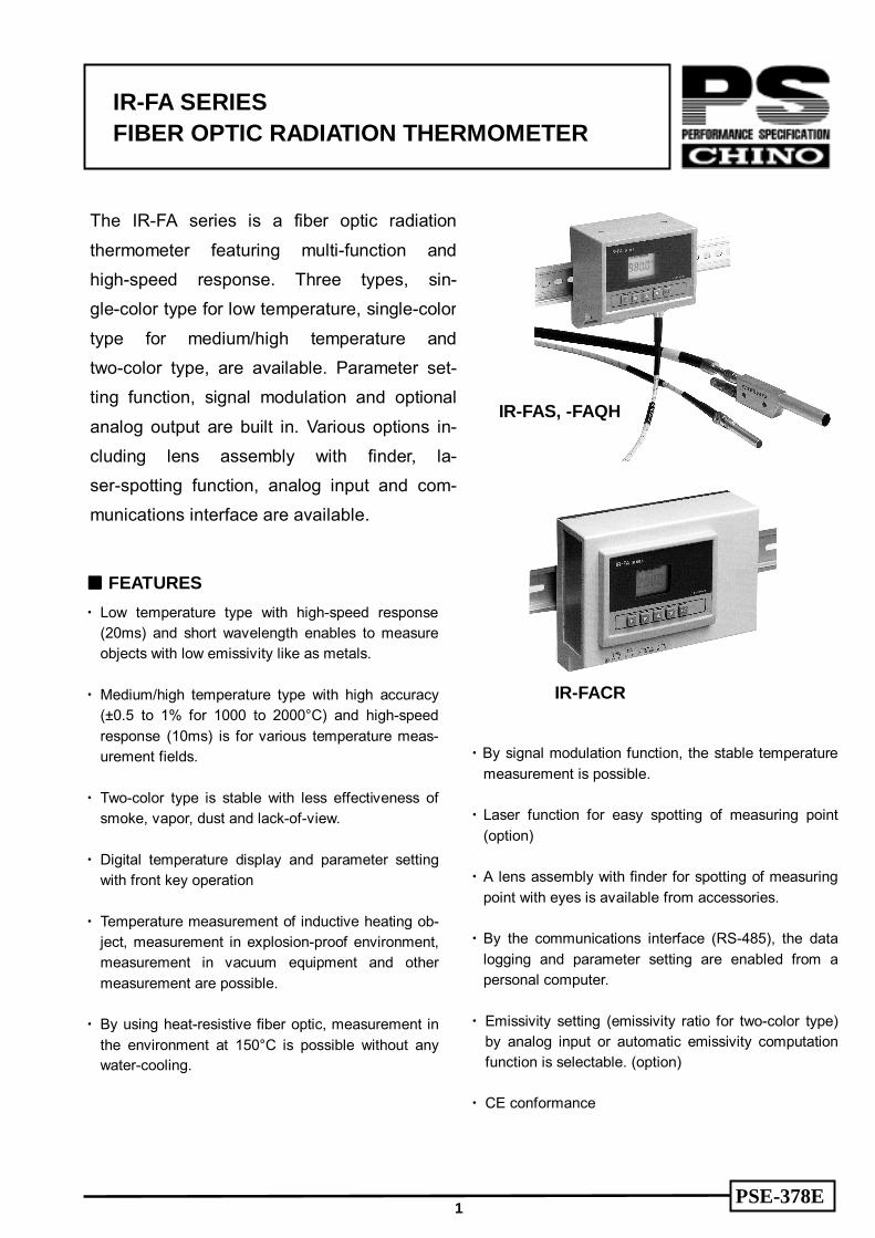
The IR-FA series is a fiber optic radiation thermometer featuring multi-function and high-speed response. Three types, sin-gle-color type for low temperature, single-color type for medium/high temperature and two-color type, are available. Parameter set-ting function, signal modulation and optional analog output are built in. Various options in-cluding lens assembly with finder, la-ser-spotting function, analog input and com-munications interface are available.
FEATURES Low temperature type with high-speed response (20ms) and short wavelength enables to measure objects with low emissivity like as metals.
Medium/high temperature type with high accuracy (±0.5 to 1% for 1000 to 2000°C) and high-speed response (10ms) is for various temperature meas-urement fields.
Two-color type is stable with less effectiveness of smoke, vapor, dust and lack-of-view.
Digital temperature display and parameter setting with front key operation
Temperature measurement of inductive heating ob-ject, measurement in explosion-proof environment, measurement in vacuum equipment and other measurement are possible.
By using heat-resistive fiber optic, measurement in the environment at 150°C is possible without any water-cooling.
By signal modulation function, the stable temperature measurement is possible.
Laser function for easy spotting of measuring point (option)
A lens assembly with finder for spotting of measuring point with eyes is available from accessories.
By the communications interface (RS-485), the data logging and parameter setting are enabled from a personal computer.
Emissivity setting (emissivity ratio for two-color type) by analog input or automatic emissivity computation function is selectable. (option)
CE conformance
IR-FA SERIES FIBER OPTIC RADIATION THERMOMETER
PSE-378E
IR-FAS, -FAQH
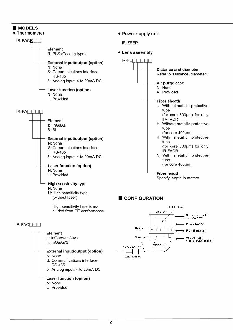
IR-FACR
2
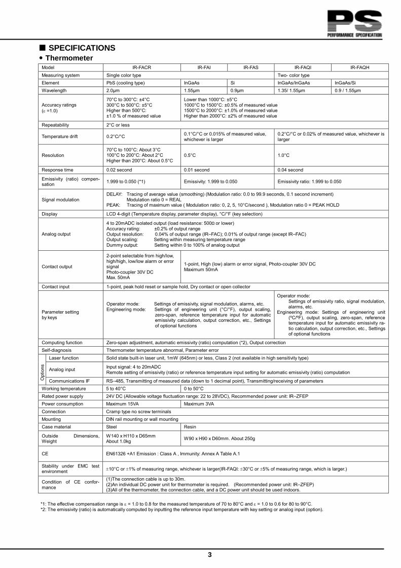
MODELS Power supply unit
IR-ZFEP
CONFIGURATION
Thermometer IR-FACR Element R: PbS (Cooling type) External input/output (option) N: None S: Communications interface RS-485 5: Analog input, 4 to 20mA DC Laser function (option) N: None L: Provided
IR-FA Element I: InGaAs S: Si External input/output (option) N: None S: Communications interface RS-485 5: Analog input, 4 to 20mA DC Laser function (option) N: None L: Provided High sensitivity type N: None U: High sensitivity type (without laser)
High sensitivity type is ex-cluded from CE conformance.
IR-FAQ Element I : InGaAs/InGaAs H: InGaAs/Si External input/output (option) N: None S: Communications interface RS-485 5: Analog input, 4 to 20mA DC Laser function (option) N: None L: Provided
Lens assembly IR-FL Distance and diameter Refer to “Distance /diameter”. Air purge case N: None A: Provided Fiber sheath J: Without metallic protective tube
(for core 800µm) for only IR-FACR
H: Without metallic protective tube
(for core 400µm) K: With metallic protective
tube (for core 800µm) for only IR-FACR
N: With metallic protective tube
(for core 400µm) Fiber length
Specify length in meters.
3
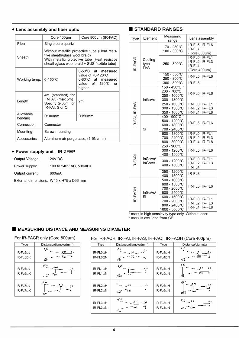
SPECIFICATIONS Thermometer
Model IR-FACR IR-FAI IR-FAS IR-FAQI IR-FAQH Measuring system Single color type Two- color type Element PbS (cooling type) InGaAs Si InGaAs/InGaAs InGaAs/Si Wavelength 2.0µm 1.55µm 0.9µm 1.35/ 1.55µm 0.9 / 1.55µm
Accuracy ratings (ε =1.0)
70°C to 300°C: ±4°C 300°C to 500°C: ±5°C Higher than 500°C: ±1.0 % of measured value
Lower than 1000°C: ±5°C 1000°C to 1500°C: ±0.5% of measured value 1500°C to 2000°C: ±1.0% of measured value Higher than 2000°C: ±2% of measured value
Repeatability 2°C or less
Temperature drift 0.2°C/°C 0.1°C/°C or 0.015% of measured value, whichever is larger
0.2°C/°C or 0.02% of measured value, whichever is larger
Resolution 70°C to 100°C: About 3°C 100°C to 200°C: About 2°C Higher than 200°C: About 0.5°C
0.5°C 1.0°C
Response time 0.02 second 0.01 second 0.04 second
Emissivity (ratio) compen-sation 1.999 to 0.050 (*1) Emissivity: 1.999 to 0.050 Emissivity ratio: 1.999 to 0.050
Signal modulation DELAY: Tracing of average value (smoothing) (Modulation ratio: 0.0 to 99.9 seconds, 0.1 second increment) Modulation ratio 0 = REAL PEAK: Tracing of maximum value ( Modulation ratio: 0, 2, 5, 10°C/second ), Modulation ratio 0 = PEAK HOLD
Display LCD 4-digit (Temperature display, parameter display), °C/°F (key selection)
Analog output
4 to 20mADC isolated output (load resistance: 500Ω or lower) Accuracy rating: ±0.2% of output range Output resolution: 0.04% of output range (IRFAC); 0.01% of output range (except IRFAC) Output scaling: Setting within measuring temperature range Dummy output: Setting within 0 to 100% of analog output
Contact output
2-point selectable from high/low, high/high, low/low alarm or error signal Photo-coupler 30V DC Max. 50mA
1-point, High (low) alarm or error signal, Photo-coupler 30V DC Maximum 50mA
Contact input 1-point, peak hold reset or sample hold, Dry contact or open collector
Parameter setting by keys
Operator mode: Settings of emissivity, signal modulation, alarms, etc. Engineering mode: Settings of engineering unit (°C/°F), output scaling,
zero-span, reference temperature input for automatic emissivity calculation, output correction, etc., Settings of optional functions
Operator mode: Settings of emissivity ratio, signal modulation, alarms, etc.
Engineering mode: Settings of engineering unit (ºC/ºF), output scaling, zero-span, reference temperature input for automatic emissivity ra-tio calculation, output correction, etc., Settings of optional functions
Computing function Zero-span adjustment, automatic emissivity (ratio) computation (*2), Output correction Self-diagnosis Thermometer temperature abnormal, Parameter error
Laser function Solid state built-in laser unit, 1mW (645nm) or less, Class 2 (not available in high sensitivity type)
Analog input Input signal: 4 to 20mADC Remote setting of emissivity (ratio) or reference temperature input setting for automatic emissivity (ratio) computation
Opt
ions
Communications IF RS485, Transmitting of measured data (down to 1 decimal point), Transmitting/receiving of parameters Working temperature 5 to 40°C 0 to 50°C Rated power supply 24V DC (Allowable voltage fluctuation range: 22 to 28VDC), Recommended power unit: IRZFEP Power consumption Maximum 15VA Maximum 3VA Connection Cramp type no screw terminals Mounting DIN rail mounting or wall mounting Case material Steel Resin
Outside Dimensions, Weight
W140 x H110 x D65mm About 1.0kg W90 x H90 x D60mm. About 250g
CE EN61326 +A1 Emission : Class A , Immunity: Annex A Table A.1
Stability under EMC test environment ±10°C or ±1% of measuring range, whichever is larger(IR-FAQI: ±30°C or ±5% of measuring range, which is larger.)
Condition of CE confor-mance
(1)The connection cable is up to 30m. (2)An individual DC power unit for thermometer is required. (Recommended power unit: IRZFEP) (3)All of the thermometer, the connection cable, and a DC power unit should be used indoors.
*1: The effective compensation range is ε = 1.0 to 0.8 for the measured temperature of 70 to 80°C and ε = 1.0 to 0.6 for 80 to 90°C. *2: The emissivity (ratio) is automatically computed by inputting the reference input temperature with key setting or analog input (option).
4
Type Element Measuring range Lens assembly
70 - 250°C 100 - 300°C
IR-FL5, IR-FL6 IR-FL7 (Core 800µm)
250 - 800°C
IR-FL0, IR-FL1 IR-FL2, IR-FL3 IR-FL4 (Core 400µm)
150 - 500°C 250 - 800°C IR-FL5, IR-FL6
IR-F
ACR
Cooling type PbS
300 - 800°C IR-FL8 150 - 450°C * 200 - 700°C 250 - 1000°C 300 - 1300°C
IR-FL5, IR-FL6 InGaAs
250 - 1000°C 300 - 1300°C 350 - 1600°C
IR-FL0, IR-FL1 IR-FL2, IR-FL3 IR-FL4, IR-FL8
400 - 900°C * 500 - 1200°C 600 - 1800°C 700 - 2400°C
IR-FL5, IR-FL6 IR-F
AI, I
R-F
AS
Si 600 - 1800°C 700 - 2400°C 800 - 3000°C
IR-FL0, IR-FL1 IR-FL2, IR-FL3 IR-FL4, IR-FL8
250 - 900°C 300 - 1200°C 400 - 1500°C
IR-FL5, IR-FL6
300 - 1200°C 400 - 1500°C
IR-FL0, IR-FL1 IR-FL2, IR-FL3 IR-FL4 IR
-FAQ
I
InGaAs/ InGaAs
350 - 1200°C 400 - 1500°C IR-FL8
500 - 1000°C 600 - 1500°C 700 - 2000°C 800 - 2400°C
IR-FL5, IR-FL6
IR-F
AQH
InGaAs/ Si 600 - 1500°C
700 - 2000°C 800 - 2400°C
1000 - 3000°C
IR-FL0, IR-FL1 IR-FL2, IR-FL3 IR-FL4, IR-FL8
* mark is high sensitivity type only. Without laser. * mark is excluded from CE.
STANDARD RANGES Core 400µm Core 800µm (IR-FAC) Fiber Single core quartz
Sheath Without metallic protective tube (Heat resis-tive sheath/glass wool braid) With metallic protective tube (Heat resistive sheath/glass wool braid + SUS flexible tube)
Working temp. 0-150°C
0-50°C at measured value of 70-120°C 0-80°C at measured value of 120°C or higher
Length 4m (standard) for IR-FAC (max.5m) Specify 2-50m for IR-FAI, S or Q
2m
Allowable bending R100mm R150mm
Connection Connector
Mounting Screw mounting
Accessories Aluminum air purge case, (1-5Nl/min)
MEASURING DISTANCE AND MEASURING DIAMETER
Output Voltage: 24V DC
Power supply: 100 to 240V AC, 50/60Hz
Output current: 600mA
External dimensions: W45 x H75 x D96 mm
Lens assembly and fiber optic
Power supply unit IR-ZFEP
For IR-FACR only (Core 800µm) For IR-FACR, IR-FAI, IR-FAS, IR-FAQI, IR-FAQH (Core 400µm) Type Distance/diameter(mm) Type Distance/diameter(mm) Type Distance/diameter
IR-FL5J IR-FL5K
IR-FL0H IR-FL0N
IR-FL4H IR-FL4N
IR-FL6J IR-FL6K
IR-FL1H IR-FL1N
IR-FL5H IR-FL5N
IR-FL7J IR-FL7K
IR-FL2H IR-FL2N
IR-FL6H IR-FL6N
IR-FL3H IR-FL3N
IR-FL8H IR-FL8N
+
5
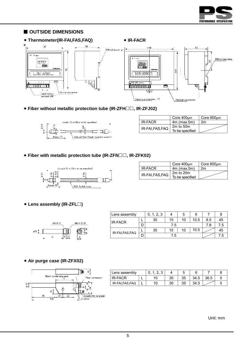
OUTSIDE DIMENSIONS Thermometer(IR-FAI,FAS,FAQ)
Fiber with metallic protection tube (IR-ZFN , IR-ZFK02)
Fiber without metallic protection tube (IR-ZFH , IR-ZFJ02)
Lens assembly (IR-ZFL )
Lens assembly 0, 1, 2, 3 4 5 6 7 8 L 35 15 10 10.5 8.5 45 IR-FACR D 7.5 7.8 7.5 L 35 15 10 10.5 45
IR-FAI,FAS,FAQ D 7.5 7.5
Core 400µm Core 800µm IR-FACR 4m (max.5m) 2m
IR-FAI,FAS,FAQ 2m to 50m To be specified
Core 400µm Core 800µm IR-FACR 4m (max.5m) 2m
IR-FAI,FAS,FAQ 2m to 20m To be specified
Air purge case (IR-ZFX02) Lens assembly 0, 1, 2, 3 4 5 6 7 8 IR-FACR L 10 30 35 34.5 36.5 0 IR-FAI,FAS,FAQ L 10 30 35 34.5 0
Unit: mm
IR-FACR
32-8, KUMANO-CHO, ITABASHI-KU, TOKYO 173-8632 PHONE: +81-3-3956-2171
FAX: +81-3-3956-0915 E-mail: [email protected]
Website: http://www.chino.co.jp
6
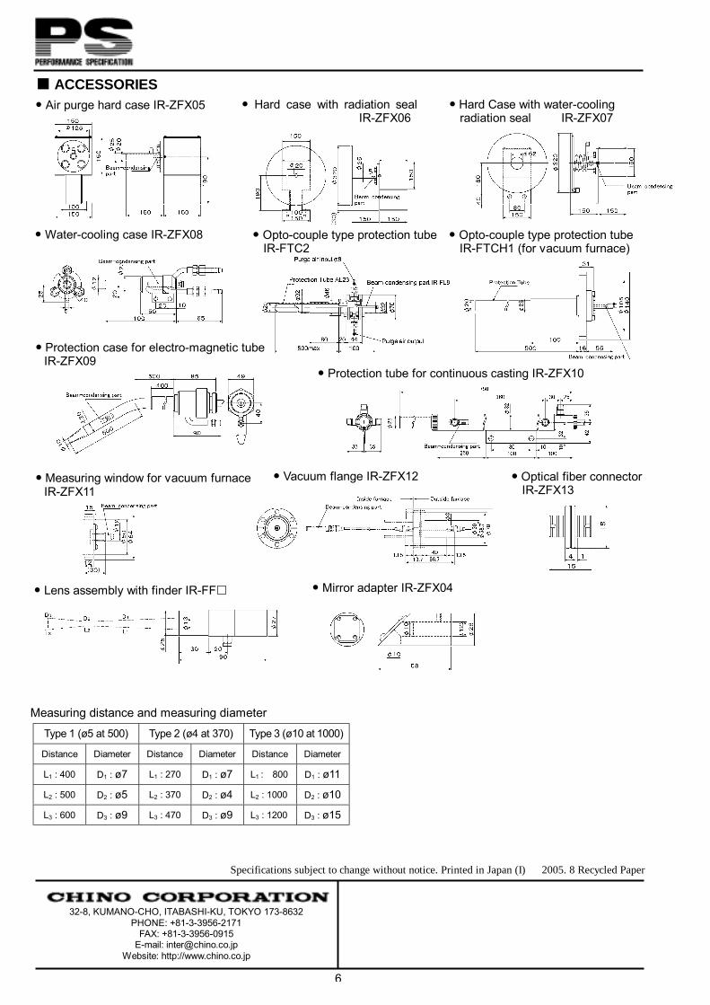
ACCESSORIES Air purge hard case IR-ZFX05 Hard Case with water-cooling
radiation seal IR-ZFX07
Water-cooling case IR-ZFX08 Opto-couple type protection tube IR-FTC2
Protection tube for continuous casting IR-ZFX10
Vacuum flange IR-ZFX12
Hard case with radiation seal IR-ZFX06
Protection case for electro-magnetic tube IR-ZFX09
Measuring window for vacuum furnace IR-ZFX11
Lens assembly with finder IR-FF Mirror adapter IR-ZFX04
Optical fiber connector IR-ZFX13
Measuring distance and measuring diameter Type 1 (ø5 at 500) Type 2 (ø4 at 370) Type 3 (ø10 at 1000)
Distance Diameter Distance Diameter Distance Diameter
L1 : 400 D1 : ø7 L1 : 270 D1 : ø7 L1 : 800 D1 : ø11
L2 : 500 D2 : ø5 L2 : 370 D2 : ø4 L2 : 1000 D2 : ø10
L3 : 600 D3 : ø9 L3 : 470 D3 : ø9 L3 : 1200 D3 : ø15
Opto-couple type protection tube IR-FTCH1 (for vacuum furnace)
Specifications subject to change without notice. Printed in Japan (I) 2005. 8 Recycled Paper