Embed Size (px)
Citation preview
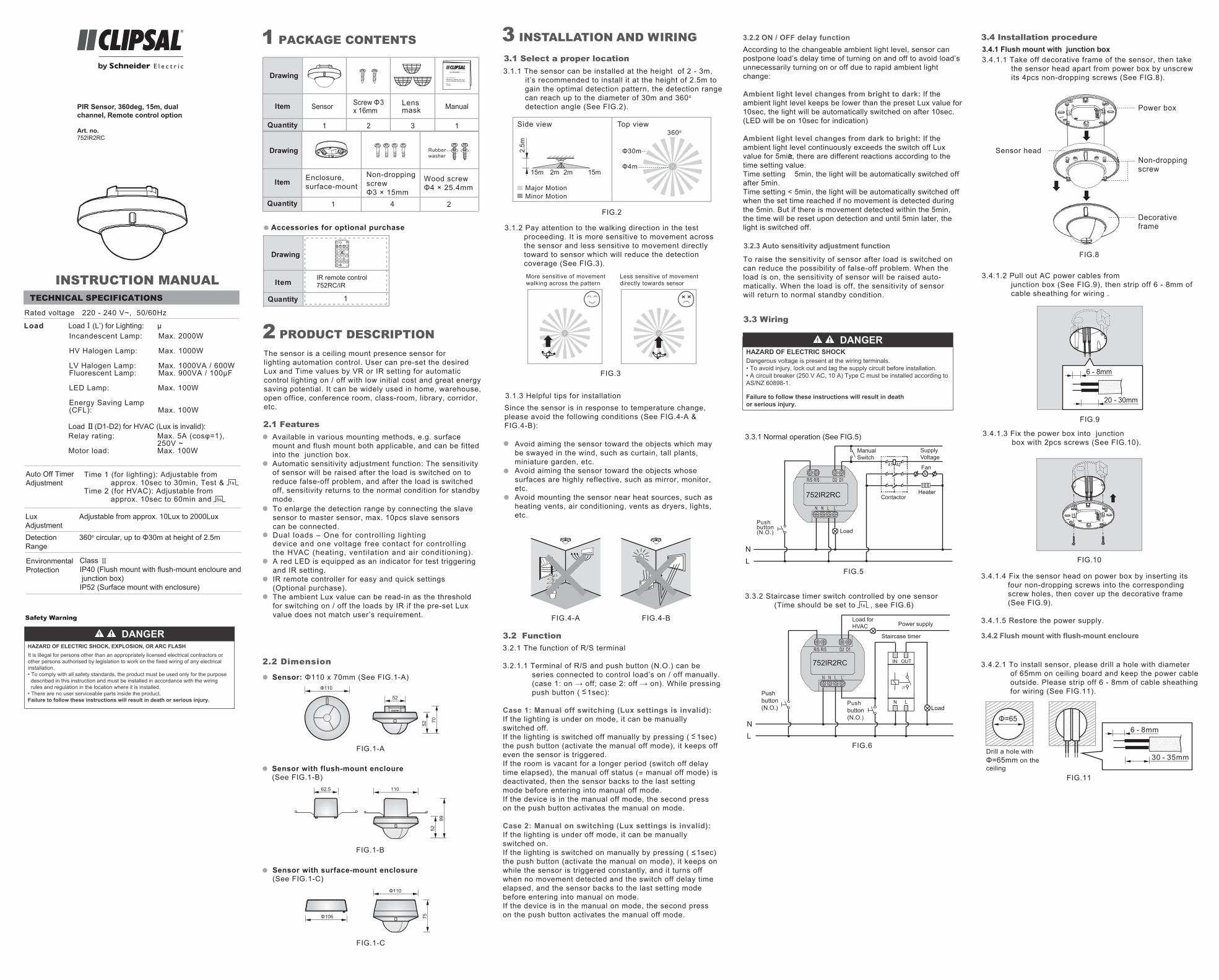
The sensor is a ceiling mount presence sensor for lighting automation control. User can pre-set the desired Lux and Time values by VR or IR setting for automatic control lighting on / off with low initial cost and great energy saving potential. It can be widely used in home, warehouse, open office, conference room, class-room, library, corridor, etc.
Available in various mounting methods, e.g. surface mount and flush mount both applicable, and can be fitted into the junction box.Automatic sensitivity adjustment function: The sensitivity of sensor will be raised after the load is switched on to reduce false-off problem, and after the load is switched off, sensitivity returns to the normal condition for standby mode.To enlarge the detection range by connecting the slave sensor to master sensor, max. 10pcs slave sensors can be connected.Dual loads – One for controll ing l ighting device and one voltage free contact for controll ing the HVAC (heating, venti lation and air conditioning).A red LED is equipped as an indicator for test triggering and IR setting. IR remote controller for easy and quick settings (Optional purchase).The ambient Lux value can be read-in as the threshold for switching on / off the loads by IR if the pre-set Lux value does not match user’s requirement.
2 PRODUCT DESCRIPTION
2.1 Features
Auto Off Timer Adjustment 1s
5s
Rated voltage 220 - 240 V~, 50/60Hz
TECHNICAL SPECIFICATIONS
INSTRUCTION MANUAL
3.4.1 Flush mount with junction box3.4.1.1 Take off decorative frame of the sensor, then take the sensor head apart from power box by unscrew its 4pcs non-dropping screws (See FIG.8).
FIG.9
6 - 8mm
20 - 30mm
3.4 Installation procedure
3.4.1.2 Pull out AC power cables from junction box (See FIG.9), then strip off 6 - 8mm of cable sheathing for wiring .
FIG.8
Non-droppingscrew
Power box
Decorativeframe
Sensor head
Time 1 (for lighting): Adjustable from approx. 10sec to 30min, Test &Time 2 (for HVAC): Adjustable from approx. 10sec to 60min and
FIG.1-C
Φ106
Φ110
75
Sensor: Φ110 x 70mm (See FIG.1-A)
Sensor with flush-mount encloure (See FIG.1-B)
FIG.1-A
FIG.1-B
2.2 Dimension
62.5
52
70
52
52
99
110
Φ110
PIR Sensor, 360deg, 15m, dual channel, Remote control option
Art. no.752IR2RC
Load
3.2.2 ON / OFF delay functionAccording to the changeable ambient light level, sensor canpostpone load’s delay time of turning on and off to avoid load’sunnecessarily turning on or off due to rapid ambient lightchange:
Ambient light level changes from bright to dark: If the ambient light level keeps be lower than the preset Lux value for10sec, the light will be automatically switched on after 10sec.(LED will be on 10sec for indication)
Ambient light level changes from dark to bright: If the ambient light level continuously exceeds the switch off Lux value for 5min, there are different reactions according to the time setting value.Time setting 5min, the light will be automatically switched offafter 5min.Time setting < 5min, the light will be automatically switched offwhen the set time reached if no movement is detected duringthe 5min. But if there is movement detected within the 5min, the time will be reset upon detection and until 5min later, the light is switched off.
<
3.2.3 Auto sensitivity adjustment function
To raise the sensitivity of sensor after load is switched on can reduce the possibility of false-off problem. When the load is on, the sensitivity of sensor will be raised auto-matically. When the load is off, the sensitivity of sensor will return to normal standby condition.
3.3 Wiring
3.3.1 Normal operation (See FIG.5)
752IR2RC
R/S
N N L L’
R/S
LoadPushbutton(N.O.)
NL
D2 D1
A1 A2
SupplyVoltage
Contactor
Fan
Heater
M
ManualSwitch
FIG.5
R/S R/S D2 D1
N N L L’
3.3.2 Staircase timer switch controlled by one sensor (Time should be set to , see FIG.6)1s
Load
Staircase timer
Pushbutton(N.O.)
Pushbutton(N.O.)
NL
752IR2RC
LN
OUTIN
μ
Load for HVAC Power supply
FIG.6
3.4.2 Flush mount with flush-mount encloure
3.4.2.1 To install sensor, please drill a hole with diameter of 65mm on ceiling board and keep the power cable outside. Please strip off 6 - 8mm of cable sheathing for wiring (See FIG.11).
FIG.11
3.4.1.3 Fix the power box into junction box with 2pcs screws (See FIG.10).
3.4.1.4 Fix the sensor head on power box by inserting its four non-dropping screws into the corresponding screw holes, then cover up the decorative frame (See FIG.9).
3.4.1.5 Restore the power supply.
Φ=656 - 8mm
30 - 35mmDrill a hole with Φ=65mm on theceiling
FIG.10
Lux Adjustment
Adjustable from approx. 10Lux to 2000Lux
360o circular, up to Φ30m at height of 2.5m
Environmental Protection
Class ⅡIP40 (Flush mount with flush-mount encloure and junction box) IP52 (Surface mount with enclosure)
DetectionRange
Safety Warning
3 INSTALLATION AND WIRING
3.1 Select a proper location
3.1.2 Pay attention to the walking direction in the test proceeding. It is more sensitive to movement across the sensor and less sensitive to movement directly toward to sensor which will reduce the detection coverage (See FIG.3).
3.1.3 Helpful tips for installation
Avoid aiming the sensor toward the objects which may be swayed in the wind, such as curtain, tall plants, miniature garden, etc.Avoid aiming the sensor toward the objects whose surfaces are highly reflective, such as mirror, monitor, etc.Avoid mounting the sensor near heat sources, such as heating vents, air conditioning, vents as dryers, lights, etc.
3.1.1 The sensor can be installed at the height of 2 - 3m, it’s recommended to install it at the height of 2.5m to gain the optimal detection pattern, the detection range can reach up to the diameter of 30m and 360o detection angle (See FIG.2).
Since the sensor is in response to temperature change, please avoid the following conditions (See FIG.4-A & FIG.4-B):
FIG.2
FIG.3
More sensitive of movementwalking across the pattern
Less sensitive of movementdirectly towards sensor
Φ30m
Φ4m
360oTop viewSide view
15m 15m
2.5m
2m 2m
Major MotionMinor Motion
3.2 Function3.2.1 The function of R/S terminal
3.2.1.1 Terminal of R/S and push button (N.O.) can be series connected to control load’s on / off manually. (case 1: on → off; case 2: off → on). While pressing push button ( 1sec):
Case 1: Manual off switching (Lux settings is invalid):If the lighting is under on mode, it can be manually switched off. If the lighting is switched off manually by pressing ( 1sec)the push button (activate the manual off mode), it keeps offeven the sensor is triggered. If the room is vacant for a longer period (switch off delay time elapsed), the manual off status (= manual off mode) is deactivated, then the sensor backs to the last setting mode before entering into manual off mode. If the device is in the manual off mode, the second press on the push button activates the manual on mode.
Case 2: Manual on switching (Lux settings is invalid):If the lighting is under off mode, it can be manually switched on.If the lighting is switched on manually by pressing ( 1sec) the push button (activate the manual on mode), it keeps onwhile the sensor is triggered constantly, and it turns off when no movement detected and the switch off delay time elapsed, and the sensor backs to the last setting mode before entering into manual on mode. If the device is in the manual on mode, the second press on the push button activates the manual off mode.
W
FIG.4-A FIG.4-B
<
<
<
DANGERHAZARD OF ELECTRIC SHOCK, EXPLOSION, OR ARC FLASHIt is illegal for persons other than an appropriately licensed electrical contractors orother persons authorised by legislation to work on the fixed wiring of any electricalinstallation.• To comply with all safety standards, the product must be used only for the purpose described in this instruction and must be installed in accordance with the wiring rules and regulation in the location where it is installed.• There are no user serviceable parts inside the product.Failure to follow these instructions will result in death or serious injury.
Incandescent Lamp: Max. 2000W
HV Halogen Lamp: Max. 1000W
LV Halogen Lamp: Max. 1000VA / 600WFluorescent Lamp: Max. 900VA / 100µF
LED Lamp: Max. 100W
Energy Saving Lamp(CFL): Max. 100W
Relay rating: Max. 5A (cosφ=1), 250V ~ Motor load: Max. 100W
LoadⅠ(L’) for Lighting: µ
Load Ⅱ(D1-D2) for HVAC (Lux is invalid):
1
Drawing
Quantity
Item IR remote control752RC/IR
10Sec.
30Min.
3Min.
15Min.
60Min.
ON OFF
MEMO
10LUX
1000LUX
100LUX
400LUX
1Min
30Min
5Min
15Min
60Min
30LUX
IR-11
LUX
TIME1
TIME2
1Sec.
5Sec.
RESET
TEST
1 PACKAGE CONTENTS
Accessories for optional purchase
Sensor
1
Drawing
Item
Quantity
Drawing
Item
Quantity 1
Manual
1
4
3
2
Lens mask
Enclosure,surface-mount
Non-droppingscrew Φ3 × 15mm
Wood screw Φ4 × 25.4mm
Rubberwasher
2
Screw Φ3x 16mm
PIR Sensor, 360deg, 15m, dual channel, Remote control option
USER MANUAL
Art. no.752IR2RC
DANGERHAZARD OF ELECTRIC SHOCKDangerous voltage is present at the wiring terminals.• To avoid injury, lock out and tag the supply circuit before installation.• A circuit breaker (250 V AC, 10 A) Type C must be installed according to AS/NZ 60898-1.
Failure to follow these instructions will result in death or serious injury.
Sensor with surface-mount enclosure (See FIG.1-C)

3.4.2.2 Use screwdriver to break the rubber gasket on flush-mount encloure, then feed cables through it (See FIG.12).3.4.2.3 Please refer to illustration of FIG.5 - FIG.6 for correct wiring and then screw the flush-mount encloure tightly.
FIG.12
Cable entry
Flush-mount encloure
Non-droppingscrewRubber gasket
3.4.3.6 Cover up the sensor’s decorative frame and restore the power supply.
3.4.3.5 Refer to wiring diagrams for correct wiring con- nection (See FIG.5 - FIG.6). There is a square hole in the fixing plate, when you put the fixing plate into the enclosure, please fit the fillister to the enclosure’s protrusion (See FIG.18), then fix the sensor head on the power box following FIG.8 and assemble them with the attached 4pcs non-dropping screws.
3.4.3.4 Insert 4pcs non-dropping screws to the correspond- ing screw holes on sensor’s fixing plate, and those 4pcs screws will not drop off to provide convenience to the subsequent installations (See FIG.17).
FIG.17
Non-droppingscrew
Non-droppingscrew
FIG.18
Non-droppingscrew
8570
6041
Square hole
Protrusion
FIG.19-B
Φ6m
A & B layers of the lens mask are used.
Φ12m
A layer of the lens mask is used.
30°
Φ6mΦ12mΦ30m
Part of the lens mask is used.
4.2.2 Fixing lens mask: There is cicular hook on the back of the decorative frame and the lens mask is designed with a circular groove. The lens shiled can be fitted by joining the groove of lens mask with its corresponding hook on the decorative frame (See FIG.20-A & FIG.20-B).
The shadow part of the lens masks in the FIG.19-A &FIG.19-B is needed to be cut off.
4.3.1 Tester must be within the detection coverage.4.3.2 Switch power on.4.3.3 The sensor takes approx. 60sec to warm up with load and LED on, then turns off after warming up time.4.3.4 Walk from outside across to the detection pattern until LED turns on for approx. 2sec then off, the next trigger should be 2sec interval (See FIG.21).4.3.5 Adjusting lens mask for desired detection range.
Test procedure
4.3 Walk test
It takes approx. 60sec for sensor to warm up after power is supplied, then enters into normal operation tocarry out a walk test.
The purpose of conducting the walk test is to check and adjust the detection coverage. Set Time knob to “Test”, then conducting a walk test and Lux is disabled.
FIG.21
FIG.20-A
FIG.20-B
Circulargroove
Circularhook
Decorative frame
HINT
4.2 Usege of lens mask
4.2.1 The sensor has supplied 3pcs lens masks to allow elimination of coverage in unwanted areas. Each lens shield has 3 layers, each layer includes 4 small units and each small unit can cover 30° detection area. For example, to install the sensor at the height of 2.5m, the detection range can reach up to 1m diameter if the complete lens masks has been used, and up to 6m diameter if layer C has been cut, as well, up to 12m diameter if layer B also has been cut, the detection range can reach up to 30m diameter when no lens shield is used.
FIG.19-A
Φ1m
CBA
The whole lens mask is used.
3.4.2.4 Close up sensor’s two spring clips and insert sensor into the drilled hole on ceiling (See FIG.13).
3.4.2.5 Restore the power supply.3.4.3 Surface mount with enclosure
NO. A B The distancebetween A and B
12
34
4160
7085
4160
7085
41mm60mm70mm85mm
FIG.14-B
3.4.3.2 To feed AC power cables through the side of enclosure, please use the cutting pliers to break the cable entry knockouts on the side of the enclosure, then insert cables into enclosure and feed through it. Strip off 6 - 8mm of cable sheathing for wiring (See FIG.15).
3.4.3.1 There are 4 pairs of knockouts with various distances from 41mm to 85mm on the bottom cover of combined enclosure can be selected for different mounting applications (See FIG.14-A). Select two same figures on both ends for the corresponding distance for fixing (See FIG.14-B).
FIG.13
FIG.14-A
A
Konckouts
Knockouts
85
85
70
70
60
60
41
41
857060
41
B
85
706041
FIG.15
6
30 - 35mm
- 8mm
Cable entryknockout
Φ= 6 8 Power cable
Spring clips
4 OPERATION AND FUNCTION4.1 Lux, Time knobs
Range: Approx. 10sec to 30minTest: Test mode (Load and red LED will be 2sec on, 2sec off) : Short impulse mode for staircase timer switch control (Load will be 1sec on, 9sec off)
Knob Function Knob setting
Set delayoff time for lighting
Set thelight valuefor switchingon load
Range: Approx. 10 to 2000Lux User can set the knob according to their requirement for application. The marked values are for reference only.
1s
Set delayoff time for HVAC
Range: Approx. 10sec to 60min (Reaction is regardless of Lux value) : Short impulse mode for staircase timer switch control (Load will be 5sec on, 5sec off)
5s
5s
3.4.3.3 Choose proper knockouts to fix the enclosure on the surface of ceiling board with 2pcs wood screws attached with rubber washer (See FIG.16).
FIG.16
85
70
70
60
60
41
41
Rubberwasher
Earthterminal
4.3.6 Repeat step 4.3.4 and 4.3.5 until it meets user's demands.
5 TROUBLE SHOOTING
Problem Possible cause Suggested solution
1. Auto off time is set too long.
2. Sensor is nuisance triggered.
3. Wired incorrectly.
1. Set auto off time to a shorter time and check the load is switched off or not according to the pre-set off time.2. Keep away from detection coverage to avoid activating sensor while doing the test.3. Make sure load and wires are connected correctly.
LED does not turn on
1. Time konb is not set to Test.2. Exceeding the detection range.
1. Time knob must be located to Test position.2. Walk in the effective detection range of 30m diameter.
Nuisance triggered
There are heat sources, highly reflective objects or any objects which may be swayed in the wind within the detection coverage.
Avoid aiming the sensor towards any heat sources,such as air conditionings, electric fans, heaters or any highly reflective surfaces. Make sure there are no swaying objects within the detection coverage.
When the sensor works abmormally, please check assumptive problems and suggested solutions in following table that will hopefully to solve your problem.
Lighting devicedoes notturn on
1. Power does not turn on.2. Wired incorrectly.3. Lux knob adjusted incorrectly.4. Malfunctioned load.
1. Switch on the power.
2. Refer to wiring diagrams for correct connection.3. Check if Lux knob are set to the correct position.4. Replace the disabled load with a new one.
Lighting devicedoes notturn off
6.1 It is strongly recommended to purchase our high quality IR remote controller 752RC/IR for easy and safe setting operations on sensor, and to own the “Lux learning” function to read-in the actual light level as threshold for switching the connected load.
6 OPTIONAL ACCESSORY
FIG.22
Remote Controller752RC/IR
IR-11
TEST
L UX
T IME 1
T IME 2
RESET
A/M
10LUX
60Min.
60Min.
10Sec.
1Min.
5Min.
3Min.
15Min.
15Min.
1sec.
5sec.
30Min.
30Min.
2000
LUX
30LUX
100
LUX
400
LUX
Schneider Electric (Australia) Pty Ltd, (Clipsal by Schneider Electric), warrants this product to be free from defects in materials and workmanship for a period of three years from the date of installation. The benefits conferred herein are in addition to any other rights and remedies you may have at law in respect to this product. Australian and New Zealand customers please see the notes below.Australia: Australian Consumer Law specifies that our goods come with guarantees that cannot be excluded. You are entitled to a replacement or refund for a major failure and compensation for any other reasonably foreseeable loss or damage. You are also entitled to have the goods repaired or replaced if the goods fail to be of acceptable quality and the failure does not amount to a major failure.New Zealand: This guarantee is in addition to and does not affect your rights under applicable law, except where that law expressly provides otherwise. The Consumer Guarantee Act 1993 (NZ) will not apply if this product is purchased for the purpose of business.
This warranty is expressly subject to the Schneider Electric product being installed, wired, tested, operated and used in accordance with our instructions and specifications. Any alterations or modifications made to the product without our permission will void the warranty. Schneider Electric will at its option repair, replace or refund any defective product. The cost of replacement or repair of a defective product is limited to the price of the product only. Schneider Electric will not be responsible for the cost of retrieving, removing, reinstalling, transporting (including return of the defective product to us) or re-testing a product.
How to make a claim: Contact your electrical wholesaler or local supplier of Schneider Electric, PDL or Clipsal branded products and provide the details of the date of purchase, description of load or connections and the circumstances of the failure. Please provide adequate particulars of the defect within 28 days of the fault occurring.
7 WARRANTY
AustraliaSchneider Electric (Australia) Pty LtdCustomer Care Australia:1300 369 233Email: customercare.au@schneider-electric.comwww.schneider-electric.com.au
New ZealandSchneider Electric (NZ) Ltd38 Business Parade South, Highbrook, East Tamaki, Manukau 2013P.O. Box 259370 Botany, Manukau 2163Telephone +64 9-829 0490, Fax +64 9-829 0491After hours service hotline:0800 735 4357 (New Zealand only)Customer Care: 0800 652 999Email: [email protected]
Technical and Sales SupportFor assistance and technical problems, contact your nearest Schneider Electric Sales representative.
Schneider Electric reserves the right to change specifications, modify designs and discontinue items without incurring obligation and whilst every effort is made to ensure that descriptions, specifications and other information in this catalogue are correct, no warranty is given in respect thereof and the company shall not be liable for any error therein.
© Schneider Electric 2016
This material is copyright under Australian and international laws. Except as permitted under the relevant law, no part of this work may be reproduced by any process without the prior written permission of and acknowledgment of Schneider Electric
NV
E51
504-
00 0
7/20
16