Embed Size (px)
Citation preview
IQMUX42 – 49
HD/SD – SDI 10/16 Channel AES/EBU
Remultimplexer with Audio Processing
Hyperion, Snell & Wilcox, IQ Modular, and RollCall are all trademarks of the Snell & Wilcox Group. Dolby E and Dolby Digital are registered trademarks of Dolby Laboratories, Inc.
All other trademarks mentioned herein are duly acknowledged. .
C
IQMUX42 – 49 Version 2 Issue 1
Page 1
Contents
Module Description ................................................................................................................. 4 Rear Panel Views..................................................................................................................... 6 Enclosures ............................................................................................................................... 7 Module Versions...................................................................................................................... 8 Features.................................................................................................................................... 9 Technical Profile .................................................................................................................... 10 Connections........................................................................................................................... 13
Input Connections ................................................................................................................ 13 Serial In ............................................................................................................................ 13 AES Unbalanced IN/OUT (IQMUX42/46) ........................................................................ 13 AES Unbalanced IN/OUT (IQMUX43/47) ........................................................................ 13 AES Balanced IN/OUT (IQMUX44/48)............................................................................. 13 AES Balanced IN/OUT (IQMUX45/49)............................................................................. 14
Output Connections ............................................................................................................. 14 Serial Digital Video Outputs ............................................................................................. 14 AES Unbalanced IN/OUT (IQMUX42/46) ........................................................................ 14 AES Unbalanced IN/OUT (IQMUX43/47) ........................................................................ 14 AES MON OUT (IQMUX 43/45/47/48 only) ..................................................................... 15 AES Balanced IN/OUT (IQMUX44/48)............................................................................. 15 AES Balanced IN/OUT (IQMUX45/49)............................................................................. 15
25 WAY D-Type Connection Details.................................................................................... 16 Example of Connection to XLR Connectors ........................................................................ 17
Card Edge Indicators ............................................................................................................ 18 Controlling the IQMUX from the RollCall Control Panel.................................................... 19
The Information Window...................................................................................................... 19 Video Input Settings............................................................................................................. 21
Specifying Valid Input Standards ..................................................................................... 21 Specifying Input Loss Conditions ..................................................................................... 21 Viewing CRC and EDH Errors.......................................................................................... 22
Video Output Settings .......................................................................................................... 22 Specifying the Video Output Standard ............................................................................. 22 Specifying a Test Pattern ................................................................................................. 23 Specifying the Video Output............................................................................................. 24 Adjusting Gain and Black Levels...................................................................................... 24 Controlling Monochrome Functions ................................................................................. 24 Force Freezing the Picture ............................................................................................... 24
Audio Processing Overview ................................................................................................. 25 Audio Processing Block Diagram......................................................................................... 25 Audio Processing Block Diagram (showing Control Panel Screens)................................... 26 SDI Demultiplexer ................................................................................................................ 27 AES Processing ................................................................................................................... 27 Audio Delay Processor ........................................................................................................ 28 Synchronizing SRCs ............................................................................................................ 28 Tone Generator.................................................................................................................... 29 Mixers 1 to 4......................................................................................................................... 29 Embedder ProcAmps........................................................................................................... 30 SDI TX.................................................................................................................................. 30 AES ProcAmps .................................................................................................................... 30 AES TX/RXs......................................................................................................................... 31 AES Monitor ......................................................................................................................... 31 Dolby E Audio Handling ....................................................................................................... 31 AES ProcAmp Settings ........................................................................................................ 33
Controlling AES Output .................................................................................................... 33 Embedded ProcAmp Group Settings................................................................................... 34
IQMUX42 – 49 Version 2 Issue 1
Page 2
Adjusting Embedded Audio Settings................................................................................ 34 Audio Mixer Settings ............................................................................................................ 34
Adjusting Audio Mix.......................................................................................................... 35 Changing a Mixer Name................................................................................................... 36 Clip Indicators................................................................................................................... 36
AES Routing Settings .......................................................................................................... 37 Specifying AES Routing ................................................................................................... 37
Monitor Routing Settings (MUX43/45/47/49 only) ............................................................... 38 Specifying Monitor Routing .............................................................................................. 38
Embedded Routing Groups Settings ................................................................................... 39 Specifying Signal Sources................................................................................................ 39
Video Delay/DolbyE (IQMUX42-45) .................................................................................... 40 Video Delay/DolbyE Auto Line (IQMUX46-49) .................................................................... 41
Video Delay Modes .......................................................................................................... 41 Minimum Audio................................................................................................................. 42 Frames ............................................................................................................................. 42 Manual H and V................................................................................................................ 43 Manual MS ....................................................................................................................... 44 Dolby E Auto Line (IQMUX46-49 Only)............................................................................ 45 Dolby E Timing ................................................................................................................. 46
Audio Delay Settings............................................................................................................ 48 Audio Delay Select-A/B .................................................................................................... 51 RollTrack .......................................................................................................................... 51 Total Delay ....................................................................................................................... 51 AES Delay 1 to 8 and Embed Delay 1 to 8 ...................................................................... 51
Embed On/Off Settings ........................................................................................................ 53 Embedder Priority............................................................................................................. 53 Group/Channel Active ...................................................................................................... 53
Embedded I/P Setup............................................................................................................ 54 PCM.................................................................................................................................. 55 Data .................................................................................................................................. 55 Mixed ................................................................................................................................ 55 Embedded Audio Input Names ........................................................................................ 56
Embedded O/P Setup .......................................................................................................... 57 Setting up Embedded Output ........................................................................................... 57
HANC and VBI Blanking Settings ........................................................................................ 58 Specifying Vertical Interval Data (VBI) Blanking Settings ................................................ 58 Specifying Horizontal Ancillary Data (HANC) Blanking Settings...................................... 59
AES I/O Setup...................................................................................................................... 60 PCM.................................................................................................................................. 61 Data .................................................................................................................................. 61 Mixed ................................................................................................................................ 61
RollTrack Settings................................................................................................................ 63 RollTrack Sources ............................................................................................................ 63 RollTrack Addresses ........................................................................................................ 63 RollTrack Commands....................................................................................................... 64 Using RollTracks .............................................................................................................. 64 Viewing RollTrack Information.......................................................................................... 64
Memory Settings .................................................................................................................. 65 Saving to Memory ............................................................................................................ 65 Recalling Memory............................................................................................................. 66
Logging................................................................................................................................... 67 RollCall Log Fields ........................................................................................................... 71
The Setup Screen ................................................................................................................ 73 Diagnostics........................................................................................................................... 74
Diagnostic Test Descriptions............................................................................................ 74 Running Diagnostic Tests ................................................................................................ 75
Operation from an Active Control Panel ............................................................................. 76 RollCall Commands............................................................................................................... 77
IQMUX42 – 49 Version 2 Issue 1
Page 3
RollTrack Audio Delay Tracking ........................................................................................ 139 Dolby-E ................................................................................................................................. 145
What is Dolby E? ............................................................................................................... 145 Dolby E and Metadata ....................................................................................................... 145 Dolby E Partner Program................................................................................................... 145 16 and 20-bit Dolby E ........................................................................................................ 145
Dolby Digital and AC3 ......................................................................................................... 146 Metadata ............................................................................................................................ 146
Ancillary Passing and Audio Embedding ......................................................................... 147 Manual Revision Record..................................................................................................... 149
IQMUX42 – 49 Version 2 Issue 1
Page 4
Module Description
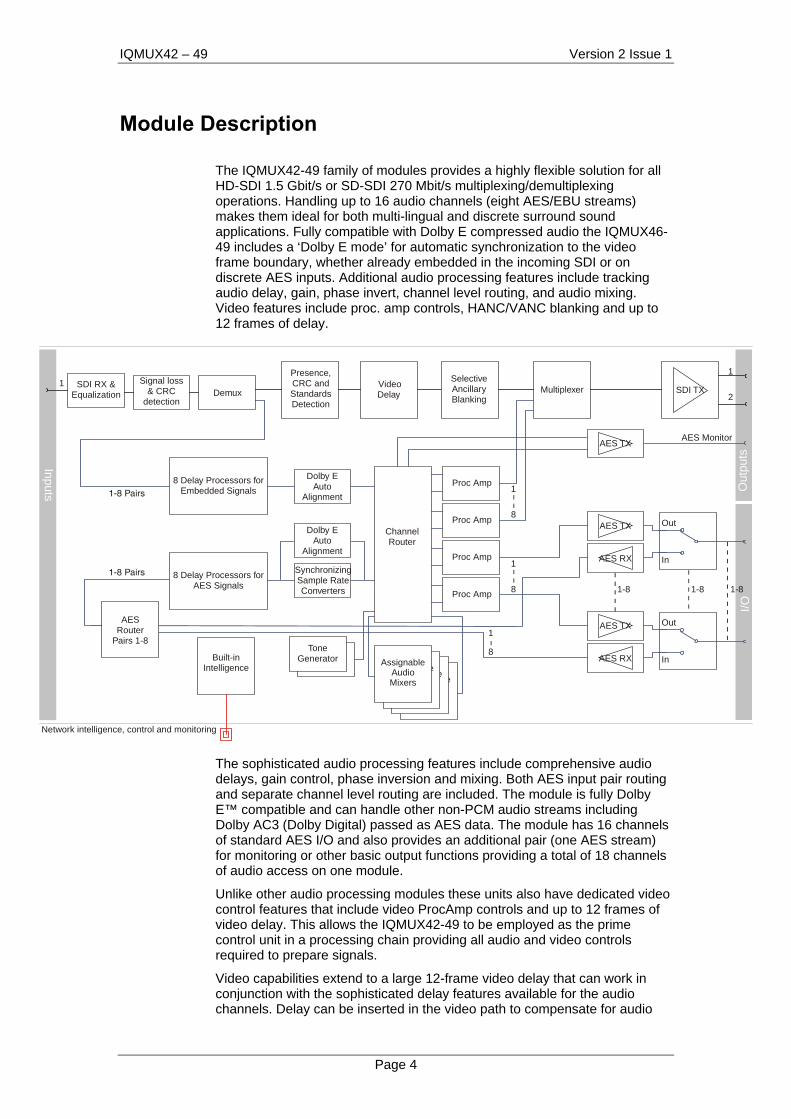
The IQMUX42-49 family of modules provides a highly flexible solution for all HD-SDI 1.5 Gbit/s or SD-SDI 270 Mbit/s multiplexing/demultiplexing operations. Handling up to 16 audio channels (eight AES/EBU streams) makes them ideal for both multi-lingual and discrete surround sound applications. Fully compatible with Dolby E compressed audio the IQMUX46-49 includes a ‘Dolby E mode’ for automatic synchronization to the video frame boundary, whether already embedded in the incoming SDI or on discrete AES inputs. Additional audio processing features include tracking audio delay, gain, phase invert, channel level routing, and audio mixing. Video features include proc. amp controls, HANC/VANC blanking and up to 12 frames of delay.
The sophisticated audio processing features include comprehensive audio delays, gain control, phase inversion and mixing. Both AES input pair routing and separate channel level routing are included. The module is fully Dolby E™ compatible and can handle other non-PCM audio streams including Dolby AC3 (Dolby Digital) passed as AES data. The module has 16 channels of standard AES I/O and also provides an additional pair (one AES stream) for monitoring or other basic output functions providing a total of 18 channels of audio access on one module.
Unlike other audio processing modules these units also have dedicated video control features that include video ProcAmp controls and up to 12 frames of video delay. This allows the IQMUX42-49 to be employed as the prime control unit in a processing chain providing all audio and video controls required to prepare signals.
Video capabilities extend to a large 12-frame video delay that can work in conjunction with the sophisticated delay features available for the audio channels. Delay can be inserted in the video path to compensate for audio
I/OO
utpu
tsInputs
SDI RX &Equalization SDI TXMultiplexer
Built-inIntelligence
Network control monitoring intelligence, and
Demux1
1
2
AES TX
1-8
Presence, CRC and Standards Detection
ChannelRouter
Selective Ancillary Blanking
AES RX
AES TX
AES RX
1-81-8
Proc Amp
Out
In
Out
In
1
8
1
8
1
8
Signal loss& CRC
detection
Proc Amp
Proc Amp
Proc Amp
AssignableAudio Mixers
AssignableAudio Mixers
AssignableAudio Mixers
AssignableAudio Mixers
ToneGenerator
ToneGenerator
8 Delay Processors for Embedded Signals
8 Delay Processors for AES Signals
SynchronizingSample Rate Converters
AESRouter
Pairs 1-8
AES TXAES Monitor
VideoDelay
Dolby EAuto
Alignment
Dolby EAuto
Alignment

IQMUX42 – 49 Version 2 Issue 1
Page 5
processing. It can also be inserted in the audio path to compensate for video processing. It can be inserted in both to simply re-time the complete signal. The audio delays can be both fixed and can track video synchronizers to keep sound in perfect sync with the pictures. The audio delay capability can be used for non PCM audio so that Dolby E sources can be delayed either to match the video or to re-time the Dolby blocks to realign with the video frames if necessary.
Also as the AES signals can be both input and output at the same time this means that these audio delay features like the other audio capabilities can be used in an AES to AES role as well as when embedding or de-embedding.
Dolby E and Dolby Digital are registered trademarks of Dolby Laboratories, Inc.
IQMUX42 – 49 Version 2 Issue 1
Page 6
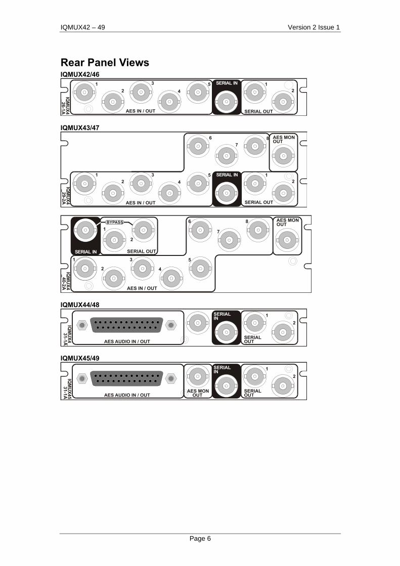
Rear Panel Views IQMUX42/46
AES IN / OUT
32 2
11 5
SERIAL OUT
IQM
UX4
_26-1A
SERIAL IN
4
IQMUX43/47 86
7
AES IN / OUT
32 2
11 5
SERIAL OUT
SERIAL IN4
AES MONOUT
IQM
UX4
_29-2A
AES IN / OUT
3
2
2
1
1 5
SERIAL OUTSERIAL IN
4
AES MONOUTBYPASS
7
6 8
IQM
UX4
_40-2 A
IQMUX44/48
IQM
UX4_
31-1A AES AUDIO IN / OUTSERIALOUT
21SERIAL
IN
IQMUX45/49
AES MONOUT
IQM
UX45
31-1A AES AUDIO IN / OUTSERIALOUT
21SERIAL
IN
IQMUX42 – 49 Version 2 Issue 1
Page 7
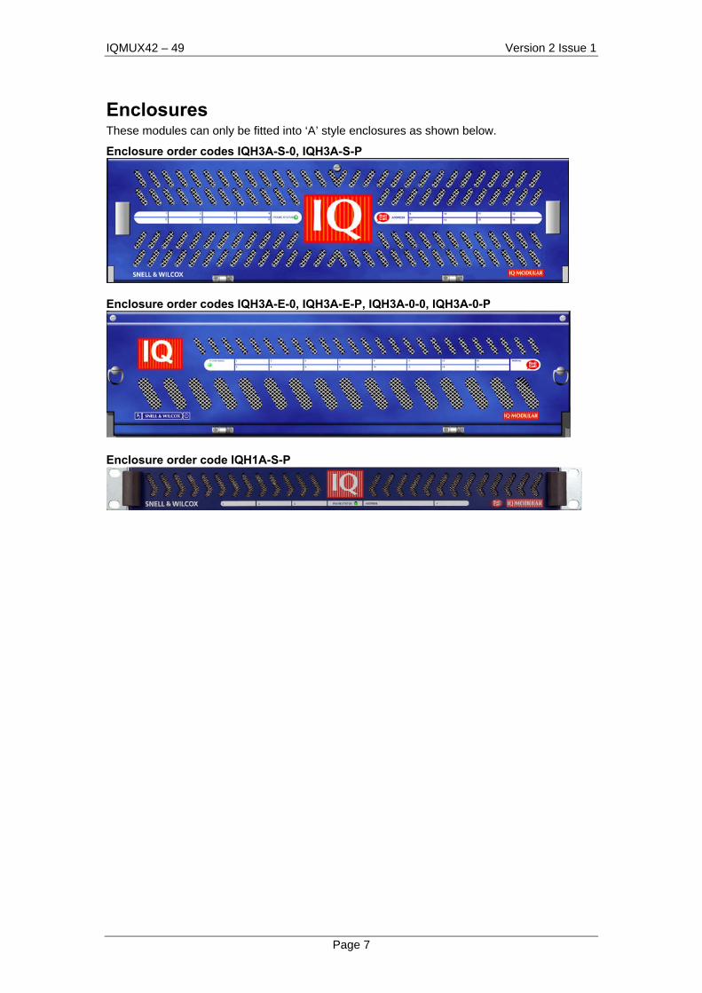
Enclosures These modules can only be fitted into ‘A’ style enclosures as shown below.
Enclosure order codes IQH3A-S-0, IQH3A-S-P
Enclosure order codes IQH3A-E-0, IQH3A-E-P, IQH3A-0-0, IQH3A-0-P
Enclosure order code IQH1A-S-P
IQMUX42 – 49 Version 2 Issue 1
Page 8
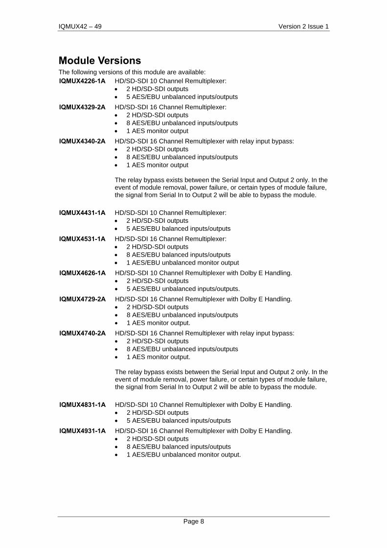
Module Versions The following versions of this module are available: IQMUX4226-1A HD/SD-SDI 10 Channel Remultiplexer:
• 2 HD/SD-SDI outputs • 5 AES/EBU unbalanced inputs/outputs
IQMUX4329-2A HD/SD-SDI 16 Channel Remultiplexer: • 2 HD/SD-SDI outputs • 8 AES/EBU unbalanced inputs/outputs • 1 AES monitor output
IQMUX4340-2A HD/SD-SDI 16 Channel Remultiplexer with relay input bypass: • 2 HD/SD-SDI outputs • 8 AES/EBU unbalanced inputs/outputs • 1 AES monitor output The relay bypass exists between the Serial Input and Output 2 only. In the event of module removal, power failure, or certain types of module failure, the signal from Serial In to Output 2 will be able to bypass the module.
IQMUX4431-1A HD/SD-SDI 10 Channel Remultiplexer: • 2 HD/SD-SDI outputs • 5 AES/EBU balanced inputs/outputs
IQMUX4531-1A HD/SD-SDI 16 Channel Remultiplexer: • 2 HD/SD-SDI outputs • 8 AES/EBU balanced inputs/outputs • 1 AES/EBU unbalanced monitor output
IQMUX4626-1A HD/SD-SDI 10 Channel Remultiplexer with Dolby E Handling. • 2 HD/SD-SDI outputs • 5 AES/EBU unbalanced inputs/outputs.
IQMUX4729-2A HD/SD-SDI 16 Channel Remultiplexer with Dolby E Handling. • 2 HD/SD-SDI outputs • 8 AES/EBU unbalanced inputs/outputs • 1 AES monitor output.
IQMUX4740-2A HD/SD-SDI 16 Channel Remultiplexer with relay input bypass: • 2 HD/SD-SDI outputs • 8 AES/EBU unbalanced inputs/outputs • 1 AES monitor output. The relay bypass exists between the Serial Input and Output 2 only. In the event of module removal, power failure, or certain types of module failure, the signal from Serial In to Output 2 will be able to bypass the module.
IQMUX4831-1A HD/SD-SDI 10 Channel Remultiplexer with Dolby E Handling. • 2 HD/SD-SDI outputs • 5 AES/EBU balanced inputs/outputs
IQMUX4931-1A HD/SD-SDI 16 Channel Remultiplexer with Dolby E Handling. • 2 HD/SD-SDI outputs • 8 AES/EBU balanced inputs/outputs • 1 AES/EBU unbalanced monitor output.
IQMUX42 – 49 Version 2 Issue 1
Page 9
Features • Multiplex unbalanced or balanced AES audio onto HD/SD-SDI video
streams with channel-level control
• Demultiplex existing audio channels and output them to unbalanced or balanced AES
• Dolby E support – pair routing and automatic re-alignment and synchronization to the video frame boundary
• Standards supported:
• HD-SDI to SMPTE292M/274M/296M
• SD-SDI to SMPTE259M-C
• Capable of processing up to 16 input audio channels to 24-bits at rates of 32 kHz, 44.1 kHz and 48 kHz both synchronous and asynchronous to the video stream
• Channel-level control allows up to 16 individual embedded audio channels to be swapped-over or swapped out
• 4 off 4 channel assignable audio mixers
• Audio proc-amp and delay
• 2 independent audio delay controls including selectable fixed delay and tracking delays for each (either selectable for any pair)
• Tracking audio delay that tracks the video delay or external RollTrack inputs
• Any group of embedded audio may be passed unchanged
• Video delay feature, up to 12 frames
• Video controls including video gain and offset
• Input SDI, CRC, EDH and ANC data checking and reporting
• Independent horizontal and vertical ancillary data blanking
• In-built test pattern generator
• Input loss detection – input pass through or black/pattern/freeze
• 16 x user memories
• Naming for audio input, mixer and output channels for easy identification
• Why should you choose this module?
• Suitable for synchronous or asynchronous multiplexing and demultiplexing HD/SD-SDI applications using AES audio
• Ideal for handling Dolby E compressed audio applications as advanced Dolby E alignment functions enable accurate timing to be maintained throughout the signal path
• Suitable for multi-lingual audio applications thanks to channel-level control and up to sixteen channel operation
IQMUX42 – 49 Version 2 Issue 1
Page 10
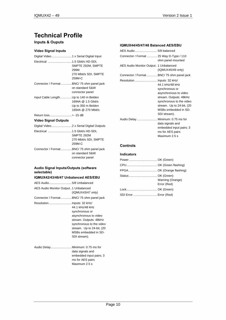
Technical Profile Inputs & Ouputs Video Signal Inputs Digital Video........................1 x Serial Digital Input
Electrical ............................1.5 Gbit/s HD-SDI, SMPTE 292M, SMPTE 299M 270 Mbit/s SDI, SMPTE 259M-C
Connector / Format .............BNC/ 75 ohm panel jack on standard S&W connector panel
Input Cable Length..............Up to 140 m Belden 1694A @ 1.5 Gbit/s Up to 350 m Belden 1694A @ 270 Mbit/s
Return loss..........................> -15 dB
Video Signal Outputs Digital Video........................2 x Serial Digital Outputs
Electrical ............................1.5 Gbit/s HD-SDI, SMPTE 292M 270 Mbit/s SDI, SMPTE 259M-C
Connector / Format .............BNC/ 75 ohm panel jack on standard S&W connector panel
Audio Signal Inputs/Outputs (software selectable) IQMUX42/43/46/47 Unbalanced AES/EBU AES Audio...........................5/8 Unbalanced
AES Audio Monitor Output..1 Unbalanced (IQMUX43/47 only)
Connector / Format .............BNC/ 75 ohm panel jack
Resolution ...........................Inputs: 32 kHz/ 44.1 kHz/48 kHz synchronous or asynchronous to video stream. Outputs: 48kHz synchronous to the video stream. Up to 24-bit, (20 MSBs embedded in SD-SDI stream).
Audio Delay.........................Minimum: 0.75 ms for data signals and embedded input pairs; 3 ms for AES pairs Maximum 2.5 s
IQMUX44/45/47/48 Balanced AES/EBU AES Audio.......................... 5/8 balanced
Connector / Format ............ 25 Way D-Type / 110 ohm panel mounted
AES Audio Monitor Output . 1 Unbalanced (IQMUX45/49 only)
Connector / Format ............ BNC/ 75 ohm panel jack
Resolution .......................... Inputs: 32 kHz/ 44.1 kHz/48 kHz synchronous or asynchronous to video stream. Outputs: 48kHz synchronous to the video stream. Up to 24-bit, (20 MSBs embedded in SD-SDI stream).
Audio Delay........................ Minimum: 0.75 ms for data signals and embedded input pairs; 3 ms for AES pairs Maximum 2.5 s
Controls Indicators Power ................................. OK (Green)
CPU.................................... OK (Green flashing)
FPGA.................................. OK (Orange flashing)
Status ................................. OK (Green) Warning (Orange) Error (Red)
Lock.................................... OK (Green)
SDI Error ............................ Error (Red)
IQMUX42 – 49 Version 2 Issue 1
Page 11
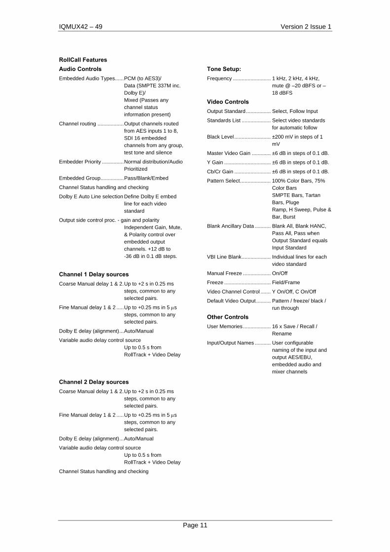
RollCall Features Audio Controls Embedded Audio Types......PCM (to AES3)/
Data (SMPTE 337M inc. Dolby E)/ Mixed (Passes any channel status information present)
Channel routing ..................Output channels routed from AES inputs 1 to 8, SDI 16 embedded channels from any group, test tone and silence
Embedder Priority ...............Normal distribution/Audio Prioritized
Embedded Group................Pass/Blank/Embed
Channel Status handling and checking
Dolby E Auto Line selection Define Dolby E embed line for each video standard
Output side control proc. - gain and polarity Independent Gain, Mute, & Polarity control over embedded output channels. +12 dB to -36 dB in 0.1 dB steps.
Channel 1 Delay sources Coarse Manual delay 1 & 2.Up to +2 s in 0.25 ms
steps, common to any selected pairs.
Fine Manual delay 1 & 2 .....Up to +0.25 ms in 5 μs steps, common to any selected pairs.
Dolby E delay (alignment)...Auto/Manual
Variable audio delay control source Up to 0.5 s from RollTrack + Video Delay
Channel 2 Delay sources Coarse Manual delay 1 & 2.Up to +2 s in 0.25 ms
steps, common to any selected pairs.
Fine Manual delay 1 & 2 .....Up to +0.25 ms in 5 μs steps, common to any selected pairs.
Dolby E delay (alignment)...Auto/Manual
Variable audio delay control source Up to 0.5 s from RollTrack + Video Delay
Channel Status handling and checking
Tone Setup: Frequency .......................... 1 kHz, 2 kHz, 4 kHz,
mute @ –20 dBFS or –18 dBFS
Video Controls Output Standard................. Select, Follow Input
Standards List .................... Select video standards for automatic follow
Black Level ......................... ±200 mV in steps of 1 mV
Master Video Gain ............. ±6 dB in steps of 0.1 dB.
Y Gain ................................ ±6 dB in steps of 0.1 dB.
Cb/Cr Gain ......................... ±6 dB in steps of 0.1 dB.
Pattern Select..................... 100% Color Bars, 75% Color Bars SMPTE Bars, Tartan Bars, Pluge Ramp, H Sweep, Pulse & Bar, Burst
Blank Ancillary Data ........... Blank All, Blank HANC, Pass All, Pass when Output Standard equals Input Standard
VBI Line Blank.................... Individual lines for each video standard
Manual Freeze ................... On/Off
Freeze ................................ Field/Frame
Video Channel Control ....... Y On/Off, C On/Off
Default Video Output .......... Pattern / freeze/ black / run through
Other Controls User Memories ................... 16 x Save / Recall /
Rename
Input/Output Names ........... User configurable naming of the input and output AES/EBU, embedded audio and mixer channels
IQMUX42 – 49 Version 2 Issue 1
Page 12
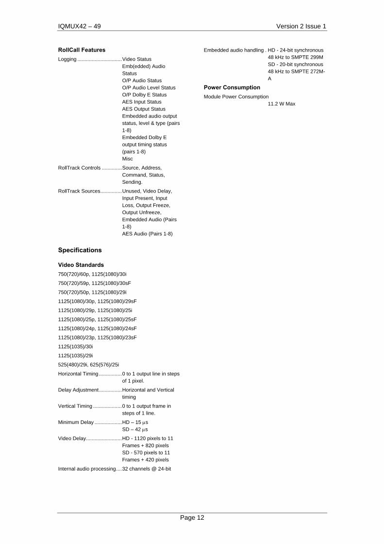
RollCall Features Logging ...............................Video Status
Emb(edded) Audio Status O/P Audio Status O/P Audio Level Status O/P Dolby E Status AES Input Status AES Output Status Embedded audio output status, level & type (pairs 1-8) Embedded Dolby E output timing status (pairs 1-8) Misc
RollTrack Controls ..............Source, Address, Command, Status, Sending.
RollTrack Sources...............Unused, Video Delay, Input Present, Input Loss, Output Freeze, Output Unfreeze, Embedded Audio (Pairs 1-8) AES Audio (Pairs 1-8)
Specifications Video Standards 750(720)/60p, 1125(1080)/30i
750(720)/59p, 1125(1080)/30sF
750(720)/50p, 1125(1080)/29i
1125(1080)/30p, 1125(1080)/29sF
1125(1080)/29p, 1125(1080)/25i
1125(1080)/25p, 1125(1080)/25sF
1125(1080)/24p, 1125(1080)/24sF
1125(1080)/23p, 1125(1080)/23sF
1125(1035)/30i
1125(1035)/29i
525(480)/29i, 625(576)/25i
Horizontal Timing ................0 to 1 output line in steps of 1 pixel.
Delay Adjustment................Horizontal and Vertical timing
Vertical Timing ....................0 to 1 output frame in steps of 1 line.
Minimum Delay ...................HD – 15 μs SD – 42 μs
Video Delay.........................HD - 1120 pixels to 11 Frames + 820 pixels SD - 570 pixels to 11 Frames + 420 pixels
Internal audio processing....32 channels @ 24-bit
Embedded audio handling . HD - 24-bit synchronous 48 kHz to SMPTE 299M SD - 20-bit synchronous 48 kHz to SMPTE 272M-A
Power Consumption Module Power Consumption
11.2 W Max
IQMUX42 – 49 Version 2 Issue 1
Page 13
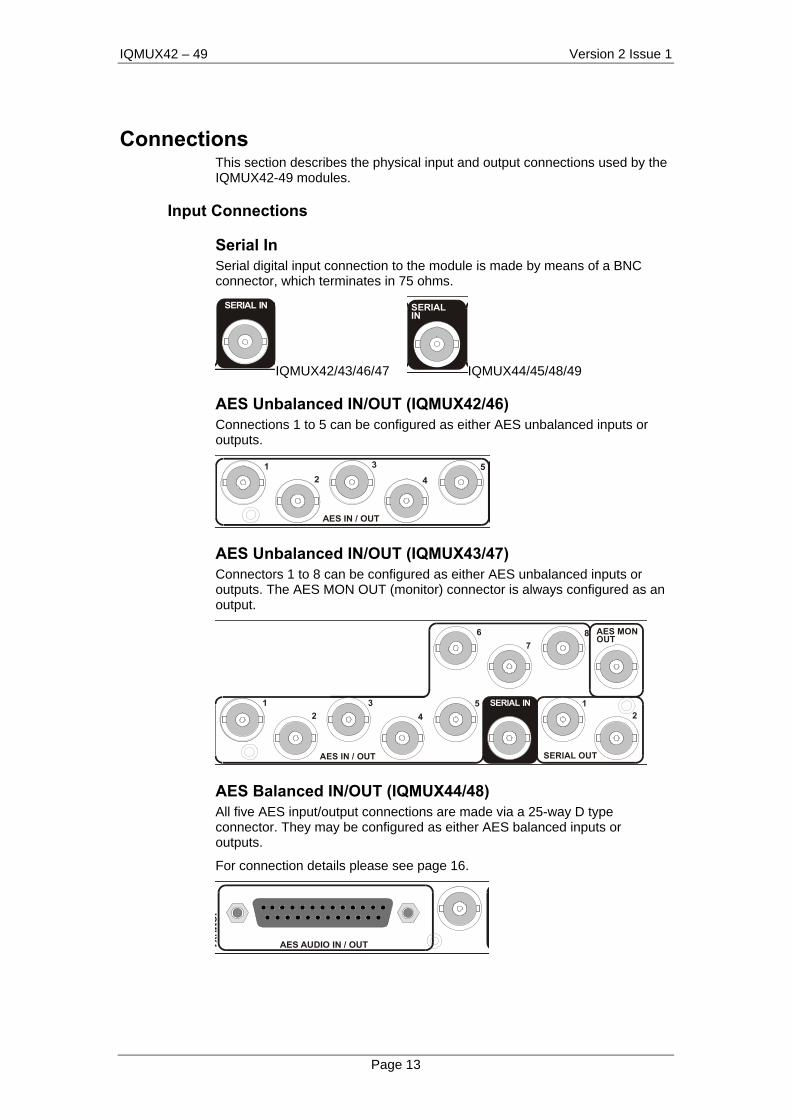
Connections This section describes the physical input and output connections used by the IQMUX42-49 modules.
Input Connections
Serial In Serial digital input connection to the module is made by means of a BNC connector, which terminates in 75 ohms.
SERIAL IN
IQMUX42/43/46/47
SERIALIN
IQMUX44/45/48/49
AES Unbalanced IN/OUT (IQMUX42/46) Connections 1 to 5 can be configured as either AES unbalanced inputs or outputs.
AES IN / OUT
32
1 54
AES Unbalanced IN/OUT (IQMUX43/47) Connectors 1 to 8 can be configured as either AES unbalanced inputs or outputs. The AES MON OUT (monitor) connector is always configured as an output.
867
AES IN / OUT
32 2
11 5
SERIAL OUT
SERIAL IN4
AES MONOUT
AES Balanced IN/OUT (IQMUX44/48) All five AES input/output connections are made via a 25-way D type connector. They may be configured as either AES balanced inputs or outputs.
For connection details please see page 16.
IQM
UX4 AES AUDIO IN / OUT
IQMUX42 – 49 Version 2 Issue 1
Page 14
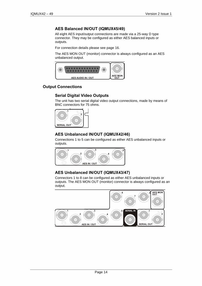
AES Balanced IN/OUT (IQMUX45/49) All eight AES input/output connections are made via a 25-way D type connector. They may be configured as either AES balanced inputs or outputs.
For connection details please see page 16.
The AES MON OUT (monitor) connector is always configured as an AES unbalanced output.
AES MONOUT
IQM
UX4 AES AUDIO IN / OUT
Output Connections
Serial Digital Video Outputs The unit has two serial digital video output connections, made by means of BNC connectors for 75 ohms.
2
1
SERIAL OUT
AES Unbalanced IN/OUT (IQMUX42/46) Connections 1 to 5 can be configured as either AES unbalanced inputs or outputs.
AES IN / OUT
32
1 54
AES Unbalanced IN/OUT (IQMUX43/47) Connectors 1 to 8 can be configured as either AES unbalanced inputs or outputs. The AES MON OUT (monitor) connector is always configured as an output.
867
AES IN / OUT
32 2
11 5
SERIAL OUT
SERIAL IN4
AES MONOUT
IQMUX42 – 49 Version 2 Issue 1
Page 15
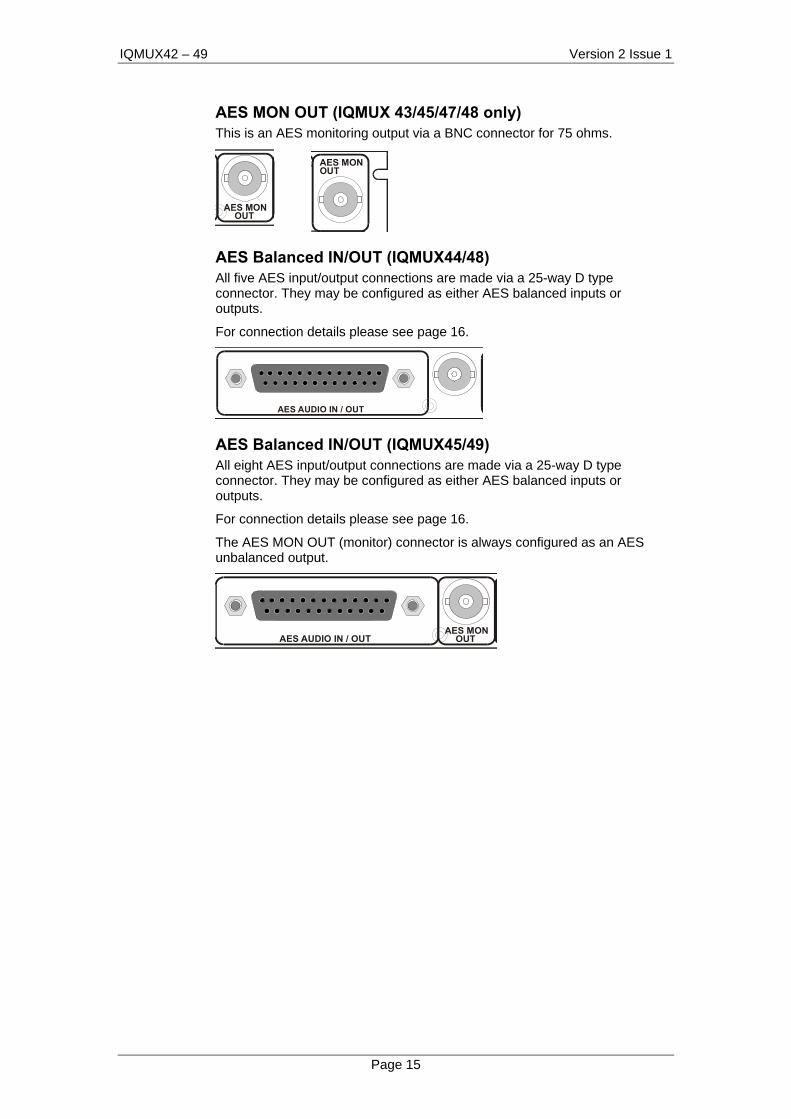
AES MON OUT (IQMUX 43/45/47/48 only) This is an AES monitoring output via a BNC connector for 75 ohms.
AES MONOUT
8 AES MONOUT
AES Balanced IN/OUT (IQMUX44/48) All five AES input/output connections are made via a 25-way D type connector. They may be configured as either AES balanced inputs or outputs.
For connection details please see page 16.
AES AUDIO IN / OUT
AES Balanced IN/OUT (IQMUX45/49) All eight AES input/output connections are made via a 25-way D type connector. They may be configured as either AES balanced inputs or outputs.
For connection details please see page 16.
The AES MON OUT (monitor) connector is always configured as an AES unbalanced output.
AES MONOUT AES AUDIO IN / OUT
IQMUX42 – 49 Version 2 Issue 1
Page 16
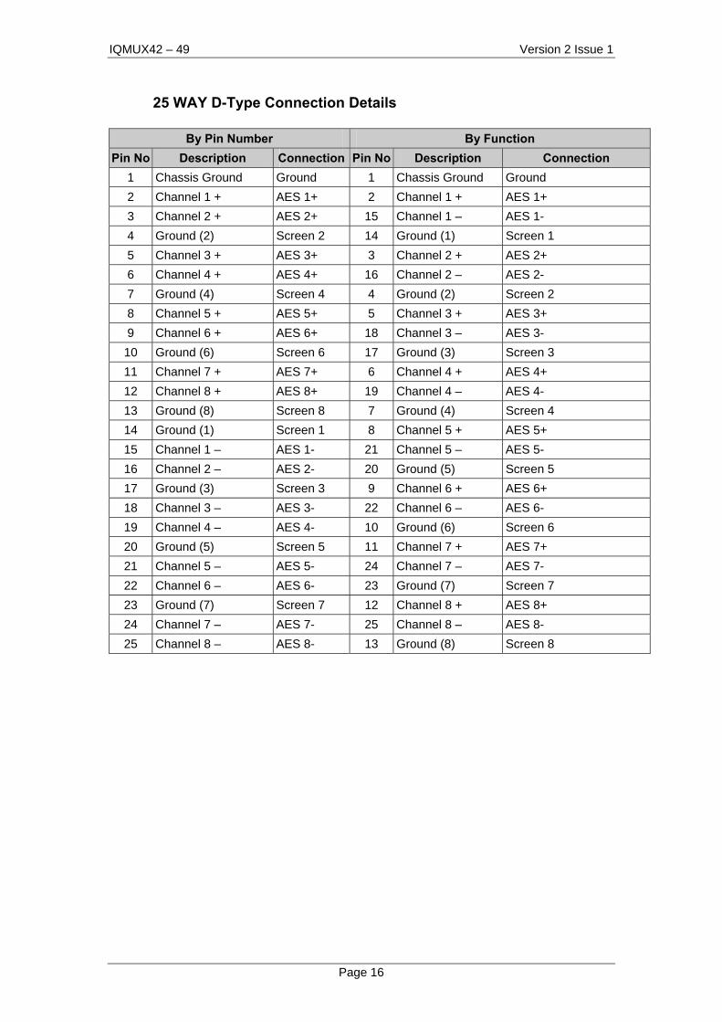
25 WAY D-Type Connection Details
By Pin Number By Function Pin No Description Connection Pin No Description Connection
1 Chassis Ground Ground 1 Chassis Ground Ground 2 Channel 1 + AES 1+ 2 Channel 1 + AES 1+ 3 Channel 2 + AES 2+ 15 Channel 1 – AES 1- 4 Ground (2) Screen 2 14 Ground (1) Screen 1 5 Channel 3 + AES 3+ 3 Channel 2 + AES 2+ 6 Channel 4 + AES 4+ 16 Channel 2 – AES 2- 7 Ground (4) Screen 4 4 Ground (2) Screen 2 8 Channel 5 + AES 5+ 5 Channel 3 + AES 3+ 9 Channel 6 + AES 6+ 18 Channel 3 – AES 3- 10 Ground (6) Screen 6 17 Ground (3) Screen 3 11 Channel 7 + AES 7+ 6 Channel 4 + AES 4+ 12 Channel 8 + AES 8+ 19 Channel 4 – AES 4- 13 Ground (8) Screen 8 7 Ground (4) Screen 4 14 Ground (1) Screen 1 8 Channel 5 + AES 5+ 15 Channel 1 – AES 1- 21 Channel 5 – AES 5- 16 Channel 2 – AES 2- 20 Ground (5) Screen 5 17 Ground (3) Screen 3 9 Channel 6 + AES 6+ 18 Channel 3 – AES 3- 22 Channel 6 – AES 6- 19 Channel 4 – AES 4- 10 Ground (6) Screen 6 20 Ground (5) Screen 5 11 Channel 7 + AES 7+ 21 Channel 5 – AES 5- 24 Channel 7 – AES 7- 22 Channel 6 – AES 6- 23 Ground (7) Screen 7 23 Ground (7) Screen 7 12 Channel 8 + AES 8+ 24 Channel 7 – AES 7- 25 Channel 8 – AES 8- 25 Channel 8 – AES 8- 13 Ground (8) Screen 8
IQMUX42 – 49 Version 2 Issue 1
Page 17
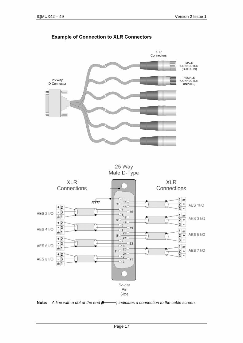
Example of Connection to XLR Connectors
25 WayD-Connector
XLRConnectors
MALE CONNECTOR(OUTPUTS)
FEMALE CONNECTOR
(INPUTS)
Note: A line with a dot at the end ( ) indicates a connection to the cable screen.
IQMUX42 – 49 Version 2 Issue 1
Page 18
Card Edge Indicators + Power OK
FPGA
- Power OK
SDI Error
CPU OK
Lock
OKWarningError
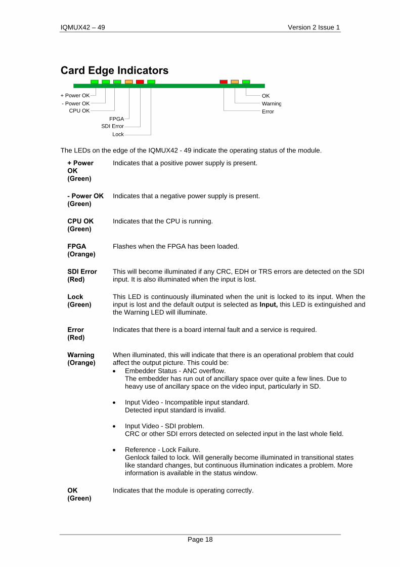
The LEDs on the edge of the IQMUX42 - 49 indicate the operating status of the module.
+ Power OK (Green)
Indicates that a positive power supply is present.
- Power OK (Green)
Indicates that a negative power supply is present.
CPU OK (Green)
Indicates that the CPU is running.
FPGA (Orange)
Flashes when the FPGA has been loaded.
SDI Error (Red)
This will become illuminated if any CRC, EDH or TRS errors are detected on the SDI input. It is also illuminated when the input is lost.
Lock (Green)
This LED is continuously illuminated when the unit is locked to its input. When the input is lost and the default output is selected as Input, this LED is extinguished and the Warning LED will illuminate.
Error (Red)
Indicates that there is a board internal fault and a service is required.
Warning (Orange)
When illuminated, this will indicate that there is an operational problem that could affect the output picture. This could be: • Embedder Status - ANC overflow.
The embedder has run out of ancillary space over quite a few lines. Due to heavy use of ancillary space on the video input, particularly in SD.
• Input Video - Incompatible input standard. Detected input standard is invalid.
• Input Video - SDI problem. CRC or other SDI errors detected on selected input in the last whole field.
• Reference - Lock Failure. Genlock failed to lock. Will generally become illuminated in transitional states like standard changes, but continuous illumination indicates a problem. More information is available in the status window.
OK (Green)
Indicates that the module is operating correctly.
IQMUX42 – 49 Version 2 Issue 1
Page 19
Controlling the IQMUX from the RollCall Control Panel The Information Window
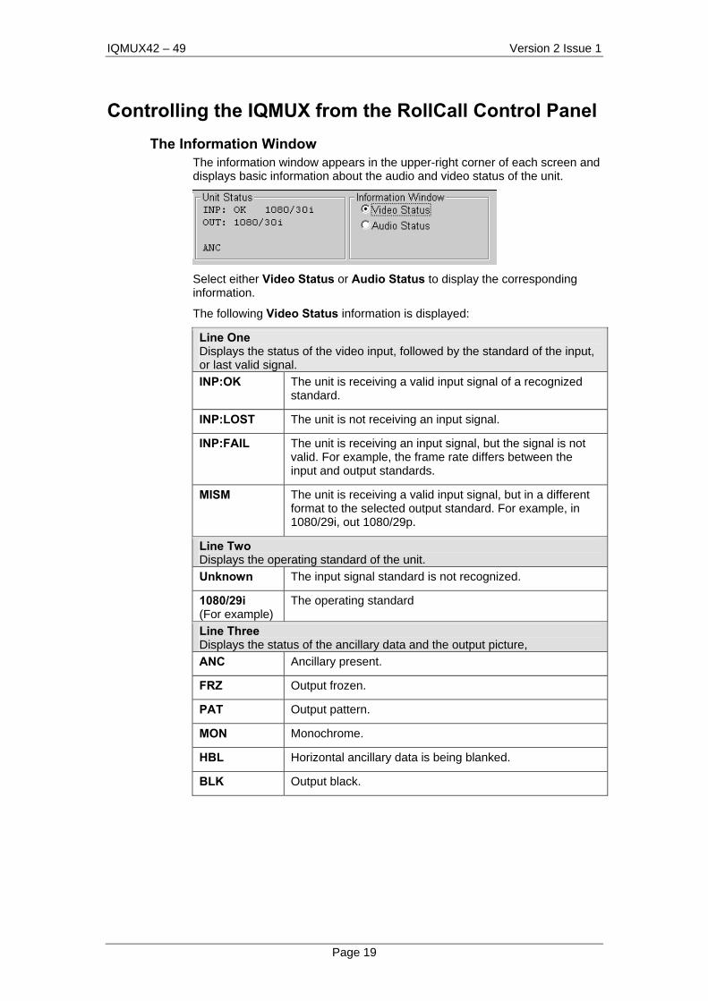
The information window appears in the upper-right corner of each screen and displays basic information about the audio and video status of the unit.
Select either Video Status or Audio Status to display the corresponding information.
The following Video Status information is displayed:
Line One Displays the status of the video input, followed by the standard of the input, or last valid signal. INP:OK The unit is receiving a valid input signal of a recognized
standard.
INP:LOST The unit is not receiving an input signal.
INP:FAIL The unit is receiving an input signal, but the signal is not valid. For example, the frame rate differs between the input and output standards.
MISM The unit is receiving a valid input signal, but in a different format to the selected output standard. For example, in 1080/29i, out 1080/29p.
Line Two Displays the operating standard of the unit. Unknown The input signal standard is not recognized.
1080/29i (For example)
The operating standard
Line Three Displays the status of the ancillary data and the output picture, ANC Ancillary present.
FRZ Output frozen.
PAT Output pattern.
MON Monochrome.
HBL Horizontal ancillary data is being blanked.
BLK Output black.
IQMUX42 – 49 Version 2 Issue 1
Page 20
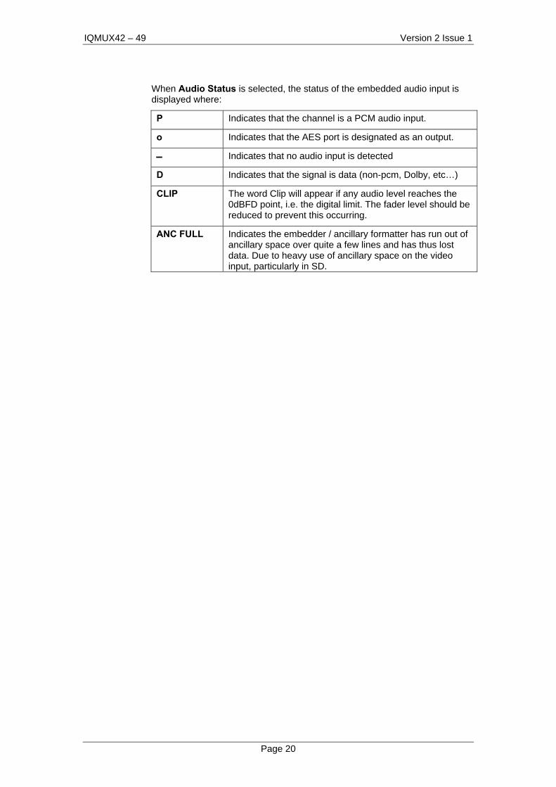
When Audio Status is selected, the status of the embedded audio input is displayed where:
P Indicates that the channel is a PCM audio input.
o Indicates that the AES port is designated as an output.
Indicates that no audio input is detected
D Indicates that the signal is data (non-pcm, Dolby, etc…)
CLIP The word Clip will appear if any audio level reaches the 0dBFD point, i.e. the digital limit. The fader level should be reduced to prevent this occurring.
ANC FULL Indicates the embedder / ancillary formatter has run out of ancillary space over quite a few lines and has thus lost data. Due to heavy use of ancillary space on the video input, particularly in SD.
IQMUX42 – 49 Version 2 Issue 1
Page 21
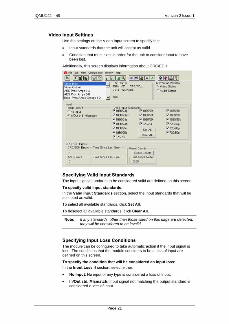
Video Input Settings Use the settings on the Video Input screen to specify the:
• Input standards that the unit will accept as valid.
• Condition that must exist in order for the unit to consider input to have been lost.
Additionally, this screen displays information about CRC/EDH.
Specifying Valid Input Standards The input signal standards to be considered valid are defined on this screen.
To specify valid input standards: In the Valid Input Standards section, select the input standards that will be accepted as valid.
To select all available standards, click Set All.
To deselect all available standards, click Clear All.
Note: If any standards, other than those listed on this page are detected, they will be considered to be invalid.
Specifying Input Loss Conditions The module can be configured to take automatic action if the input signal is lost. The conditions that the module considers to be a loss of input are defined on this screen.
To specify the condition that will be considered an input loss: In the Input Loss if section, select either:
• No Input: No input of any type is considered a loss of input.
• In/Out std. Mismatch: Input signal not matching the output standard is considered a loss of input.
IQMUX42 – 49 Version 2 Issue 1
Page 22
Viewing CRC and EDH Errors The Video Input screen also displays Cyclic Redundancy Checksum and Error Detection Handling errors.
The following CRC and EDH Error information is displayed in the CRC/EDH Errors section:
• CRC/EDH Errors: Displays the number of CRC and EDH errors that have occurred since the last reset.
• Time Since Last Error: Displays the time (in seconds) since the last CRC or EDH error was detected.
• ANC Errors: This displays the number of ANC errors since the last reset.
To reset the error counts to zero, click Reset Counts. Time Since Reset displays the time since the error counts were last reset.
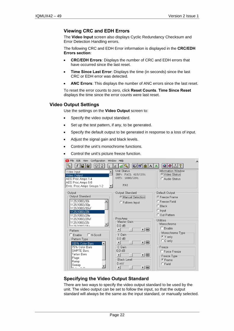
Video Output Settings Use the settings on the Video Output screen to:
• Specify the video output standard.
• Set up the test pattern, if any, to be generated.
• Specify the default output to be generated in response to a loss of input.
• Adjust the signal gain and black levels.
• Control the unit’s monochrome functions.
• Control the unit’s picture freeze function.
Specifying the Video Output Standard There are two ways to specify the video output standard to be used by the unit. The video output can be set to follow the input, so that the output standard will always be the same as the input standard, or manually selected.
IQMUX42 – 49 Version 2 Issue 1
Page 23
When manually selected, the output standard will always be the one specified, regardless of the input signal.
To allow the output standard to follow the input standard: In the Output Standard section, select Follows Input.
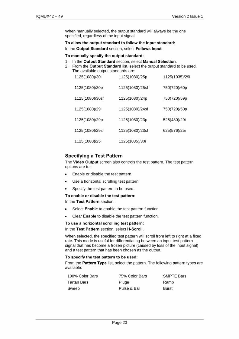
To manually specify the output standard: 1. In the Output Standard section, select Manual Selection. 2. From the Output Standard list, select the output standard to be used.
The available output standards are: 1125(1080)/30i
1125(1080)/25p
1125(1035)/29i
1125(1080)/30p
1125(1080)/25sf
750(720)/60p
1125(1080)/30sf
1125(1080)/24p
750(720)/59p
1125(1080)/29i
1125(1080)/24sf
750(720)/50p
1125(1080)/29p
1125(1080)/23p
525(480)/29i
1125(1080)/29sf
1125(1080)/23sf
625(576)/25i
1125(1080)/25i
1125(1035)/30i
Specifying a Test Pattern The Video Output screen also controls the test pattern. The test pattern options are to:
• Enable or disable the test pattern.
• Use a horizontal scrolling test pattern.
• Specify the test pattern to be used.
To enable or disable the test pattern: In the Test Pattern section:
• Select Enable to enable the test pattern function.
• Clear Enable to disable the test pattern function.
To use a horizontal scrolling test pattern: In the Test Pattern section, select H-Scroll.
When selected, the specified test pattern will scroll from left to right at a fixed rate. This mode is useful for differentiating between an input test pattern signal that has become a frozen picture (caused by loss of the input signal) and a test pattern that has been chosen as the output.
To specify the test pattern to be used: From the Pattern Type list, select the pattern. The following pattern types are available:
100% Color Bars 75% Color Bars SMPTE Bars Tartan Bars Pluge Ramp Sweep Pulse & Bar Burst
IQMUX42 – 49 Version 2 Issue 1
Page 24
Specifying the Video Output The Default Output setting defines the output that the unit generates in response to a loss of video input as specified by the Input Loss If setting on the Video Input screen.
To specify the default output: In the Default Output section, select one of the following:
• Freeze Frame: On loss of input, the output becomes a non-interpolated frozen frame picture. All HANC and VANC are blanked.
• Freeze Field: On loss of input, the output becomes a frozen field one picture. All HANC and VANC are blanked.
• Black: On loss of input, the picture cuts to black.
• Input: The incoming signal will be displayed when ever possible.
• Out Pattern: On loss of signal, the specified test pattern is displayed.
Adjusting Gain and Black Levels Use the ProcAmp functions to adjust the gain and black levels of the signal.
To adjust the gain and black levels: In the ProcAmp section, adjust the following settings as required:
• Master Gain: Adjusts the overall gain (Y and Cb/Cr) over a range of ±6 dB in steps of 0.1 dB. The preset value is 0.0 dB.
• Y Gain: Adjusts the Y (luminance) gain over a range of ±6 dB in steps of 0.1 dB. The preset value is 0.0 dB.
• C Gain: Adjusts the Cb/Cr (color difference) gain over a range of ±6 dB in steps of 0.1 dB. The preset value is 0.0 dB.
Note: The total range of both Master + Y and Master + C controls is +6dB in steps of 0.1 dB. Preset value is 0dB.
• Black Level: Adjusts the black level over a range of ±200 mV in steps of 1 mV. The preset value is 0 mV.
Controlling Monochrome Functions The unit can be set so that the output picture becomes monochrome using either the Y or Cb/Cr components of the signal.
To output a monochrome signal: 1. In the Monochrome Section, select one of the following:
• Y only: The output picture becomes monochrome using only the Y component of the signal.
• C only: the output picture becomes monochrome using only the Cb/Cr component of the signal.
2. Select Enable.
Force Freezing the Picture The unit can impose a force freeze on the picture. When this is done, the output becomes a frozen frame or frozen field.
To force freeze the output: 1. In the Freeze Type section select either
• Frame: The picture becomes a frozen frame. • Field: The picture becomes a frozen field.
2. Select Force Freeze.
IQMUX42 – 49 Version 2 Issue 1
Page 25
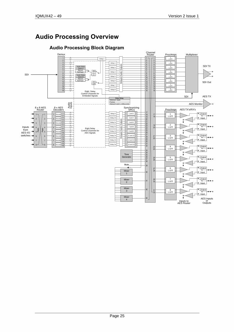
Audio Processing Overview Audio Processing Block Diagram
Del
ayed
Aud
io O
utpu
tsD
elay
ed A
udio
Out
puts
Delay 2
Delay 10
Delay 9
Delay 3
Delay 11
Delay 4
Delay 12
Delay 5
Delay 13
Delay 6
Delay 14
Delay 7
Delay 15
Delay 8
Delay 16
Eight Delay Control Channels for
Embeded Signals
Eight Delay Control Channels for
AES Signals
Audio DelaySelect A
Audio DelaySelect B
RollTrack
RollTrack
Manual
Manual
Mixer1
Mixer2
Mixer3
Mixer4
SDI
ChannelRouter ProcAmps
ProcAmps
Inputs to AES Router
AES Inputsor
Outputs
Multiplexer
SDI TX
SDI Out
AES TX
AES TX’s/RX’s
AES Monitor
1L & R
2L & R
3L & R
4L & R
5L & R
6L & R
7L & R
8L & R
1L & R
Output
Input
2L & R
Output
Input
7L & R
Output
Input
6L & R
Output
Input
5L & R
Output
Input
4L & R
Output
Input
3L & R
Output
Input
8L & R
Output
Input
SDI
Inputsfrom
AES I/O switches
8 x 8 AESRouter
Pai
rs
Pai
rs
Demux
8 x AESDecoders
Decode
Decode
Decode
Decode
Decode
Decode
Decode
Decode
SynchronizingSRCs
3 and 4
1 and 2
5 and 6
7 and 8
9 and10
11 and 12
13 and 14
15 and 16
Delay 1
Minimum AudioVideo Delay
Manual H and V, millisecondsFrames
Aud
ioIn
puts
MinAB
OffInt
IQMUX42 – 49 Version 2 Issue 1
Page 26
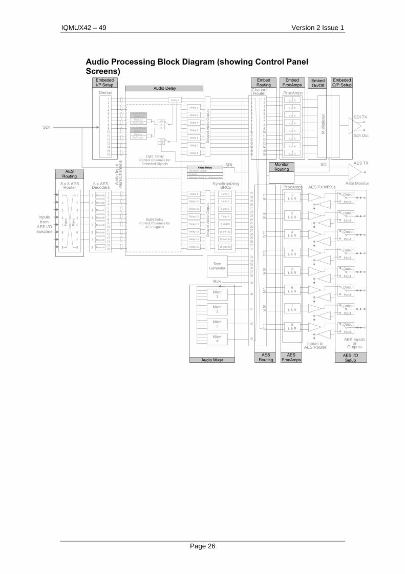
Audio Processing Block Diagram (showing Control Panel Screens)
Aud
io In
put
Pai
rs/C
hann
els
Del
ayed
Aud
io O
utpu
tsD
elay
ed A
udio
Out
puts
Delay 2
Delay 10
Delay 9
Delay 3
Delay 11
Delay 4
Delay 12
Delay 5
Delay 13
Delay 6
Delay 14
Delay 7
Delay 15
Delay 8
Delay 16
Eight Delay Control Channels for
Embeded Signals
Eight Delay Control Channels for
AES Signals
Mixer1
Mixer2
Mixer3
Mixer4
SDISDI
ChannelRouter ProcAmps
ProcAmps
Inputs to AES Router
AES Inputsor
Outputs
Mul
tiple
xer
SDI TX
SDI Out
AES TX
AES TX’s/RX’sAES Monitor
1L & R
2L & R
3L & R
4L & R
5L & R
6L & R
7L & R
8L & R
1L & R
Output
Input
2L & R
Output
Input
7L & R
Output
Input
6L & R
Output
Input
5L & R
Output
Input
4L & R
Output
Input
3L & R
Output
Input
8L & R
Output
Input
SDI
Inputsfrom
AES I/O switches
8 x 8 AESRouter
Pai
rs
Pai
rs
Demux
8 x AESDecoders
Decode
Decode
Decode
Decode
Decode
Decode
Decode
Decode
SynchronizingSRCs
3 and 4
1 and 2
5 and 6
7 and 8
9 and10
11 and 12
13 and 14
15 and 16
Audio Delay
Audio DelaySelect A
Audio DelaySelect B
RollTrack
RollTrack
Manual
Manual
Minimum Audio
Manual H and V, millisecondsFrames
Delay 1
MinAB
OffInt
Video Delay
IQMUX42 – 49 Version 2 Issue 1
Page 27
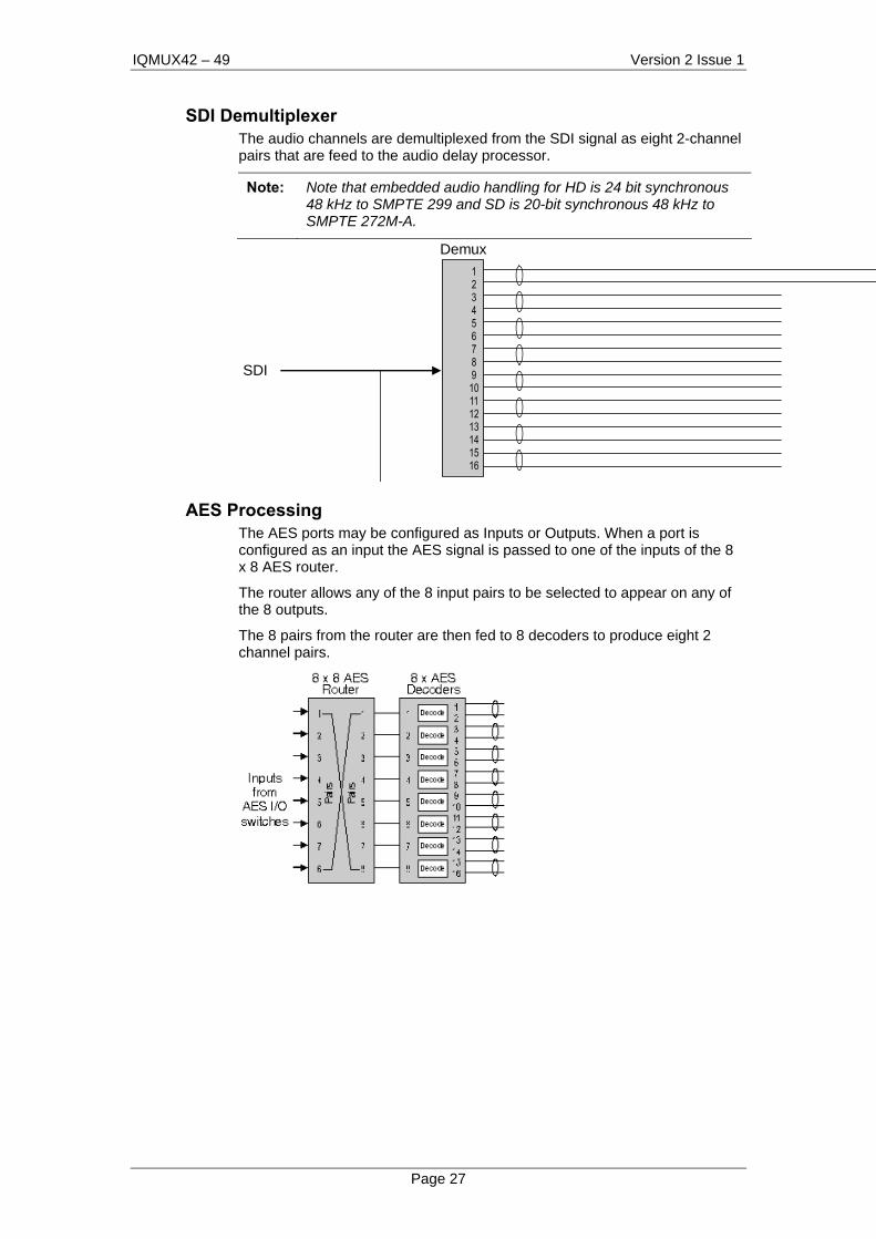
SDI Demultiplexer The audio channels are demultiplexed from the SDI signal as eight 2-channel pairs that are feed to the audio delay processor.
Note: Note that embedded audio handling for HD is 24 bit synchronous 48 kHz to SMPTE 299 and SD is 20-bit synchronous 48 kHz to SMPTE 272M-A.
SDI
Demux
AES Processing The AES ports may be configured as Inputs or Outputs. When a port is configured as an input the AES signal is passed to one of the inputs of the 8 x 8 AES router.
The router allows any of the 8 input pairs to be selected to appear on any of the 8 outputs.
The 8 pairs from the router are then fed to 8 decoders to produce eight 2 channel pairs.
IQMUX42 – 49 Version 2 Issue 1
Page 28
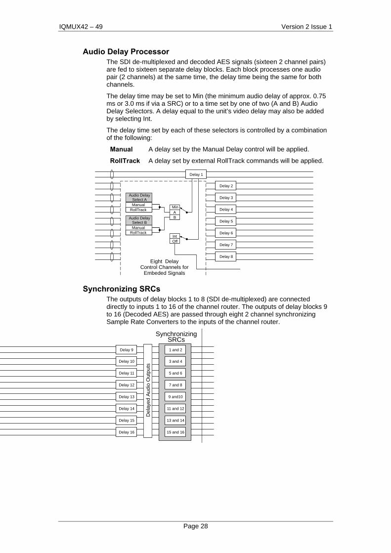
Audio Delay Processor The SDI de-multiplexed and decoded AES signals (sixteen 2 channel pairs) are fed to sixteen separate delay blocks. Each block processes one audio pair (2 channels) at the same time, the delay time being the same for both channels.
The delay time may be set to Min (the minimum audio delay of approx. 0.75 ms or 3.0 ms if via a SRC) or to a time set by one of two (A and B) Audio Delay Selectors. A delay equal to the unit’s video delay may also be added by selecting Int.
The delay time set by each of these selectors is controlled by a combination of the following:
Manual A delay set by the Manual Delay control will be applied.
RollTrack A delay set by external RollTrack commands will be applied.
Delay 2
Delay 3
Delay 4
Delay 5
Delay 6
Delay 7
Delay 8Eight Delay
Control Channels for Embeded Signals
Audio DelaySelect A
Audio DelaySelect B
RollTrack
RollTrack
Manual
Manual
Delay 1
MinAB
OffInt
Synchronizing SRCs The outputs of delay blocks 1 to 8 (SDI de-multiplexed) are connected directly to inputs 1 to 16 of the channel router. The outputs of delay blocks 9 to 16 (Decoded AES) are passed through eight 2 channel synchronizing Sample Rate Converters to the inputs of the channel router.
Del
ayed
Aud
io O
utpu
ts
Delay 10
Delay 9
Delay 11
Delay 12
Delay 13
Delay 14
Delay 15
Delay 16
SynchronizingSRCs
3 and 4
1 and 2
5 and 6
7 and 8
9 and10
11 and 12
13 and 14
15 and 16
IQMUX42 – 49 Version 2 Issue 1
Page 29
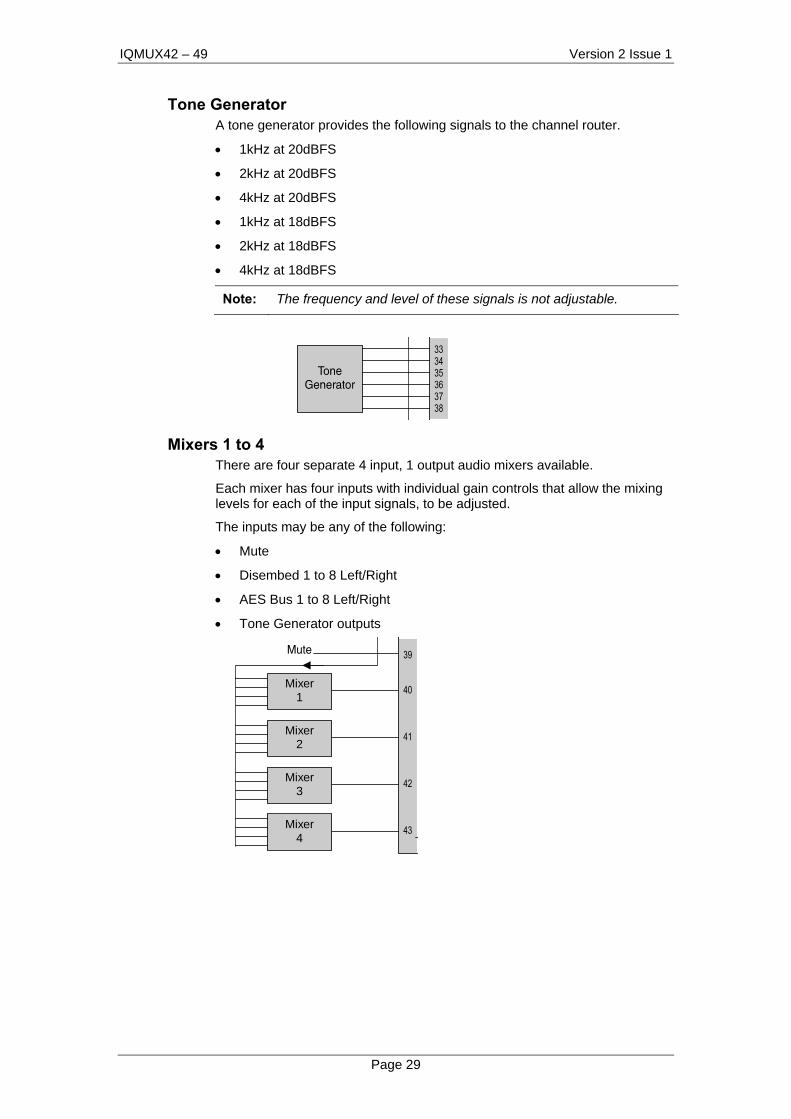
Tone Generator A tone generator provides the following signals to the channel router.
• 1kHz at 20dBFS
• 2kHz at 20dBFS
• 4kHz at 20dBFS
• 1kHz at 18dBFS
• 2kHz at 18dBFS
• 4kHz at 18dBFS
Note: The frequency and level of these signals is not adjustable.
Mixers 1 to 4 There are four separate 4 input, 1 output audio mixers available.
Each mixer has four inputs with individual gain controls that allow the mixing levels for each of the input signals, to be adjusted.
The inputs may be any of the following:
• Mute
• Disembed 1 to 8 Left/Right
• AES Bus 1 to 8 Left/Right
• Tone Generator outputs
Mixer1
Mixer2
Mixer3
Mixer4
IQMUX42 – 49 Version 2 Issue 1
Page 30
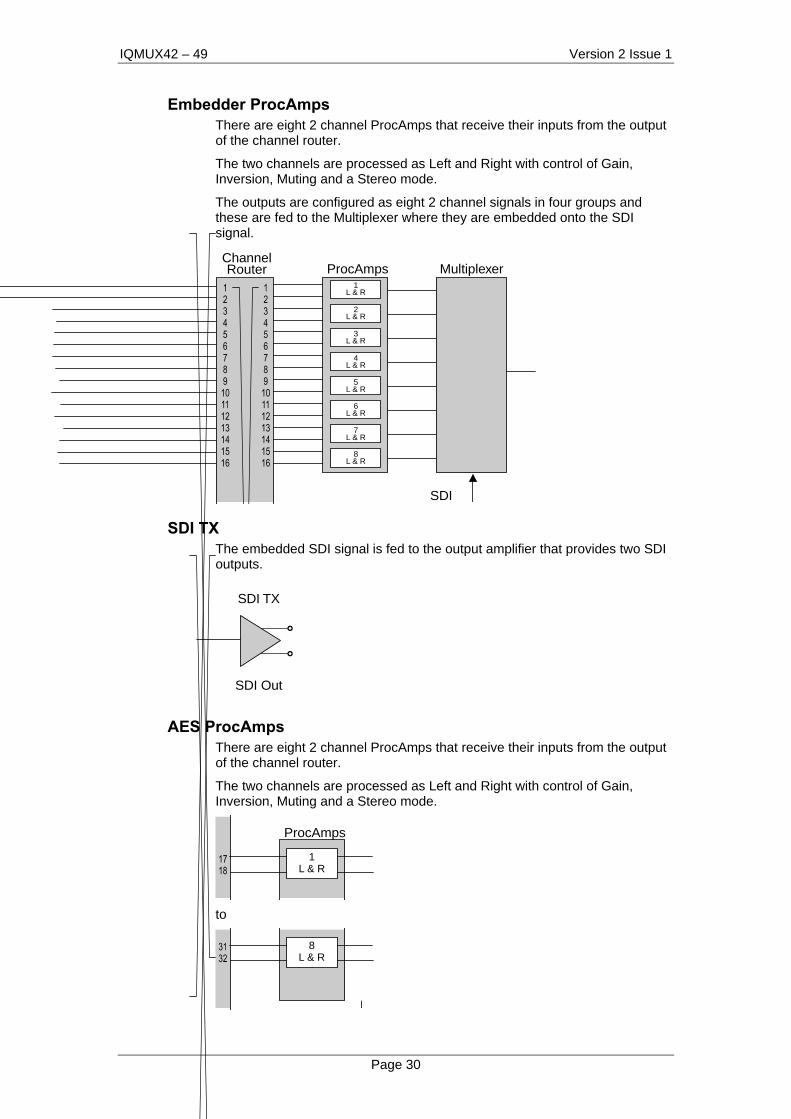
Embedder ProcAmps There are eight 2 channel ProcAmps that receive their inputs from the output of the channel router.
The two channels are processed as Left and Right with control of Gain, Inversion, Muting and a Stereo mode.
The outputs are configured as eight 2 channel signals in four groups and these are fed to the Multiplexer where they are embedded onto the SDI signal.
SDI
ChannelRouter ProcAmps Multiplexer
1L & R
2L & R
3L & R
4L & R
5L & R
6L & R
7L & R
8L & R
SDI TX The embedded SDI signal is fed to the output amplifier that provides two SDI outputs.
SDI TX
SDI Out
AES ProcAmps There are eight 2 channel ProcAmps that receive their inputs from the output of the channel router.
The two channels are processed as Left and Right with control of Gain, Inversion, Muting and a Stereo mode.
ProcAmps
1L & R
to
I
8L & R
IQMUX42 – 49 Version 2 Issue 1
Page 31
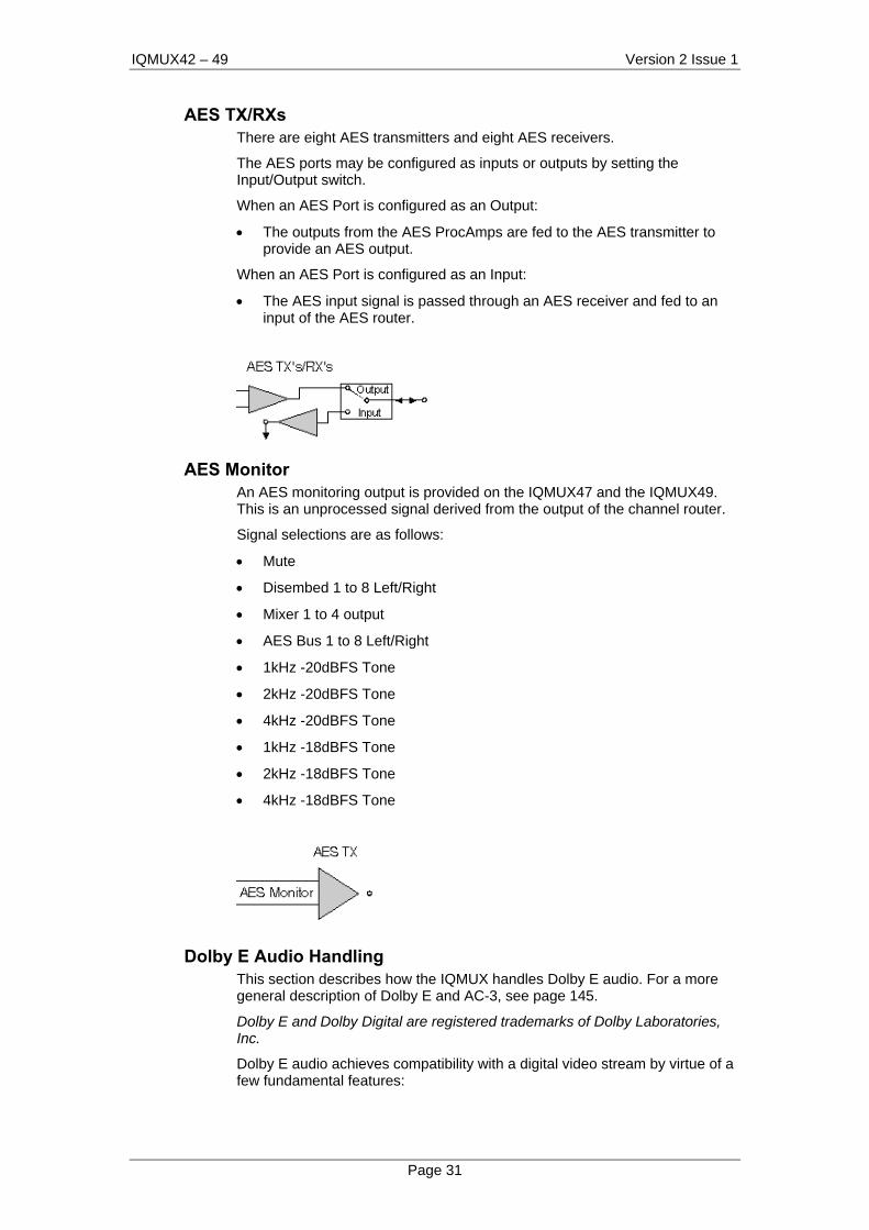
AES TX/RXs There are eight AES transmitters and eight AES receivers.
The AES ports may be configured as inputs or outputs by setting the Input/Output switch.
When an AES Port is configured as an Output:
• The outputs from the AES ProcAmps are fed to the AES transmitter to provide an AES output.
When an AES Port is configured as an Input:
• The AES input signal is passed through an AES receiver and fed to an input of the AES router.
AES Monitor An AES monitoring output is provided on the IQMUX47 and the IQMUX49. This is an unprocessed signal derived from the output of the channel router.
Signal selections are as follows:
• Mute
• Disembed 1 to 8 Left/Right
• Mixer 1 to 4 output
• AES Bus 1 to 8 Left/Right
• 1kHz -20dBFS Tone
• 2kHz -20dBFS Tone
• 4kHz -20dBFS Tone
• 1kHz -18dBFS Tone
• 2kHz -18dBFS Tone
• 4kHz -18dBFS Tone
Dolby E Audio Handling This section describes how the IQMUX handles Dolby E audio. For a more general description of Dolby E and AC-3, see page 145.
Dolby E and Dolby Digital are registered trademarks of Dolby Laboratories, Inc.
Dolby E audio achieves compatibility with a digital video stream by virtue of a few fundamental features:
IQMUX42 – 49 Version 2 Issue 1
Page 32
• The compressed audio data is broken into frame-duration packets to match the video frames it will be embedded in.
• Each frame is separated from neighboring frames by a guardband, which allows for clean video-type switching.
• Concealment of switches is possible at a decoder, based on redundant audio and block counts in each frame.
However, there is a burden in dealing with a number of parallel frame-based carriers (such as Dolby E) alongside, and often within, the video. Namely:
• Each Dolby E stream, within an AES-3 / SMPTE-337 data pair, must be synchronous and aligned with the video to allow a video stream to be switched or recorded cleanly. Incorrect alignment can lead to muting, or even high amplitude noise bursts.
As with SMPTE RP-168 switching, there is a small alignment tolerance. Upstream switched, or externally provided sources can present problematic deviations from the preferred Dolby E frame position.
• Each video standard has its own specified Dolby E frame alignment point. Thus, a standards-agile broadcast environment must arrange for correct referencing and delay adjustment in each standard.
• The embedding of audio within the video stream adds considerable timing uncertainy, and increases susceptibility to external factors such as loading of ancillary space and audio sample distribution produced by equipment in the video chain. In particular, standard definition is more prone to these issues than high definition.
The IQMUX is well equipped to deal with issues of carrying Dolby E audio within a broadcast environment. It has the tools required for the correct and easy handling of Dolby E in the following features:
• Transport enablers such as SMPTE-337 aware routing and channel status passing.
• Monitoring and logging of Dolby E frame timing for both passed and newly-embedded audio.
• Manual alignment facilities for consistently arranged environments.
• Automatic realignment of Dolby E frames to preferred or non-standard positions.
For more information about the Dolby E controls, refer to the following sections:
• Embed On/Off on page 53.
• Video Delay/Dolby E on page 41.
• O/P Dolby E Logging on page 67.
IQMUX42 – 49 Version 2 Issue 1
Page 33
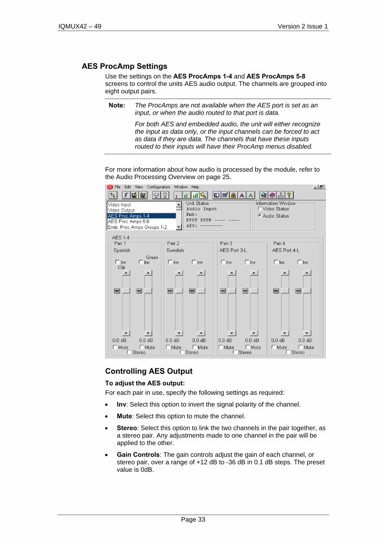
AES ProcAmp Settings Use the settings on the AES ProcAmps 1-4 and AES ProcAmps 5-8 screens to control the units AES audio output. The channels are grouped into eight output pairs.
Note: The ProcAmps are not available when the AES port is set as an input, or when the audio routed to that port is data.
For both AES and embedded audio, the unit will either recognize the input as data only, or the input channels can be forced to act as data if they are data. The channels that have these inputs routed to their inputs will have their ProcAmp menus disabled.
For more information about how audio is processed by the module, refer to the Audio Processing Overview on page 25.
Controlling AES Output To adjust the AES output: For each pair in use, specify the following settings as required:
• Inv: Select this option to invert the signal polarity of the channel.
• Mute: Select this option to mute the channel.
• Stereo: Select this option to link the two channels in the pair together, as a stereo pair. Any adjustments made to one channel in the pair will be applied to the other.
• Gain Controls: The gain controls adjust the gain of each channel, or stereo pair, over a range of +12 dB to -36 dB in 0.1 dB steps. The preset value is 0dB.
IQMUX42 – 49 Version 2 Issue 1
Page 34
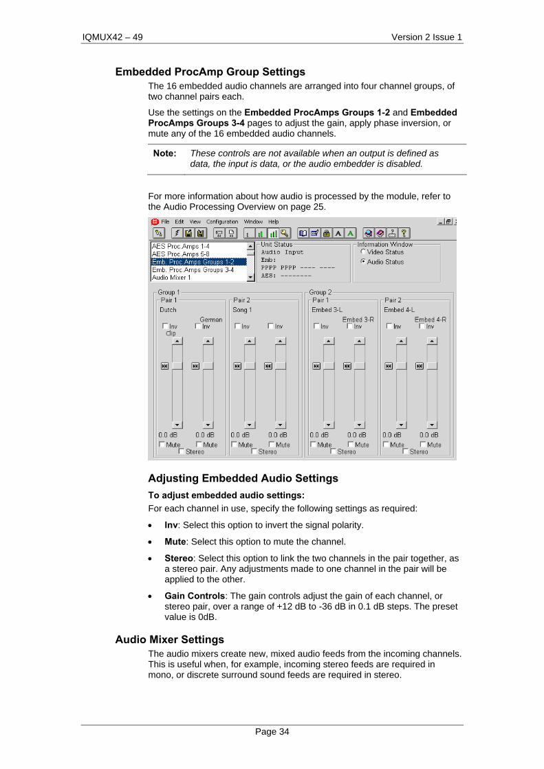
Embedded ProcAmp Group Settings The 16 embedded audio channels are arranged into four channel groups, of two channel pairs each.
Use the settings on the Embedded ProcAmps Groups 1-2 and Embedded ProcAmps Groups 3-4 pages to adjust the gain, apply phase inversion, or mute any of the 16 embedded audio channels.
Note: These controls are not available when an output is defined as data, the input is data, or the audio embedder is disabled.
For more information about how audio is processed by the module, refer to the Audio Processing Overview on page 25.
Adjusting Embedded Audio Settings To adjust embedded audio settings: For each channel in use, specify the following settings as required:
• Inv: Select this option to invert the signal polarity.
• Mute: Select this option to mute the channel.
• Stereo: Select this option to link the two channels in the pair together, as a stereo pair. Any adjustments made to one channel in the pair will be applied to the other.
• Gain Controls: The gain controls adjust the gain of each channel, or stereo pair, over a range of +12 dB to -36 dB in 0.1 dB steps. The preset value is 0dB.
Audio Mixer Settings The audio mixers create new, mixed audio feeds from the incoming channels. This is useful when, for example, incoming stereo feeds are required in mono, or discrete surround sound feeds are required in stereo.
IQMUX42 – 49 Version 2 Issue 1
Page 35
Not only can the incoming feeds be mixed together, but the exact balance can be set using the faders. This allows finer control over the resulting sound than a simple mono function.
Additional applications include mixing together incoming audio with local foreground, such as adding commentary to a sports feed. The invert function can be applied to a channel, to create a mix-minus channel for foldback.
For more information about how audio is processed by the module, refer to the Audio Processing Overview on page 25.
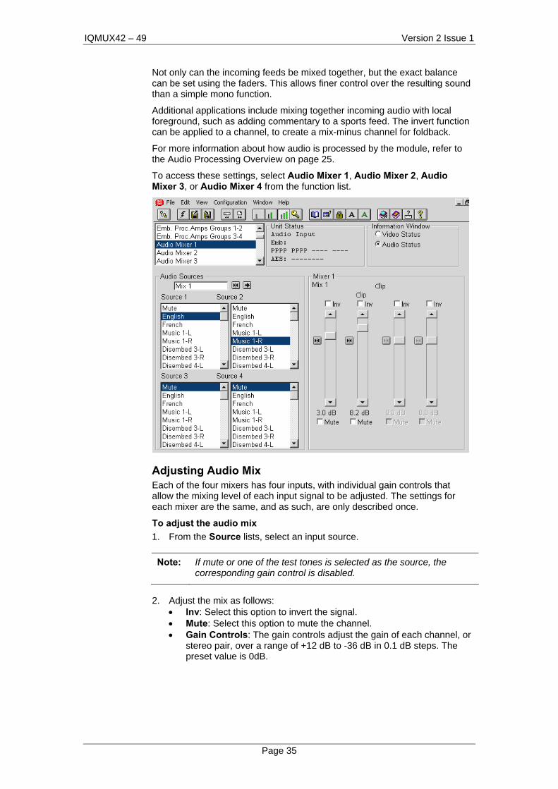
To access these settings, select Audio Mixer 1, Audio Mixer 2, Audio Mixer 3, or Audio Mixer 4 from the function list.
Adjusting Audio Mix Each of the four mixers has four inputs, with individual gain controls that allow the mixing level of each input signal to be adjusted. The settings for each mixer are the same, and as such, are only described once.
To adjust the audio mix 1. From the Source lists, select an input source.
Note: If mute or one of the test tones is selected as the source, the
corresponding gain control is disabled.
2. Adjust the mix as follows:
• Inv: Select this option to invert the signal. • Mute: Select this option to mute the channel. • Gain Controls: The gain controls adjust the gain of each channel, or
stereo pair, over a range of +12 dB to -36 dB in 0.1 dB steps. The preset value is 0dB.
IQMUX42 – 49 Version 2 Issue 1
Page 36
Changing a Mixer Name To change the name of a mixer: 1. In the text field at the top of the Audio Sources section, type the new
mixer name. The arrow button turns red .
2. Click the arrow button . The symbol turns black and the new name appears in the gain control section.
To return to the default mixer name, click the preset button .
Clip Indicators At the top of each fader the word Clip appears briefly if the audio level reaches the 0 dBFS point – reduce the fader level to prevent this from happening.
IQMUX42 – 49 Version 2 Issue 1
Page 37
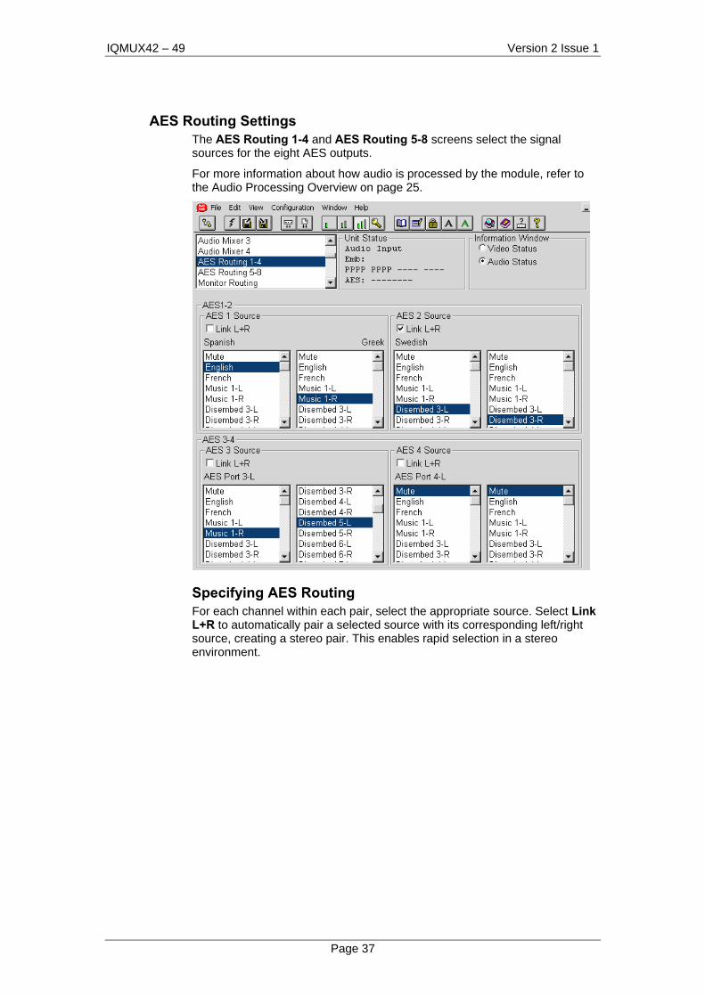
AES Routing Settings The AES Routing 1-4 and AES Routing 5-8 screens select the signal sources for the eight AES outputs.
For more information about how audio is processed by the module, refer to the Audio Processing Overview on page 25.
Specifying AES Routing For each channel within each pair, select the appropriate source. Select Link L+R to automatically pair a selected source with its corresponding left/right source, creating a stereo pair. This enables rapid selection in a stereo environment.
IQMUX42 – 49 Version 2 Issue 1
Page 38
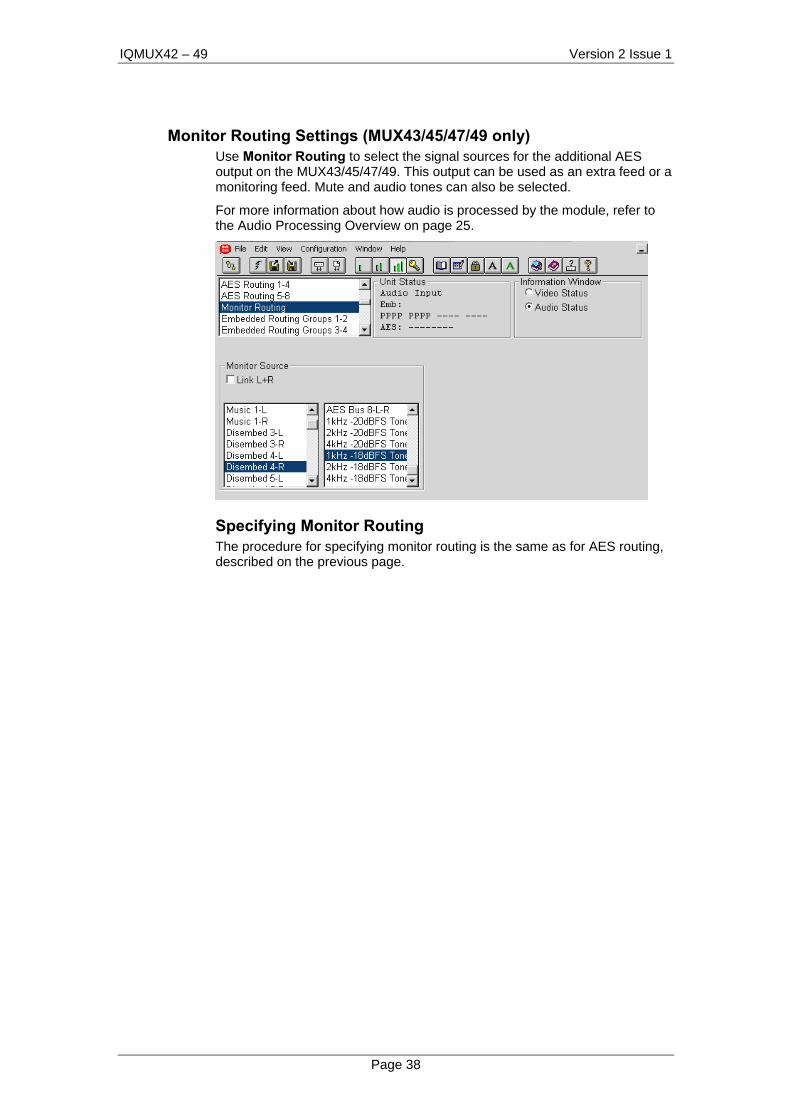
Monitor Routing Settings (MUX43/45/47/49 only) Use Monitor Routing to select the signal sources for the additional AES output on the MUX43/45/47/49. This output can be used as an extra feed or a monitoring feed. Mute and audio tones can also be selected.
For more information about how audio is processed by the module, refer to the Audio Processing Overview on page 25.
Specifying Monitor Routing The procedure for specifying monitor routing is the same as for AES routing, described on the previous page.
IQMUX42 – 49 Version 2 Issue 1
Page 39
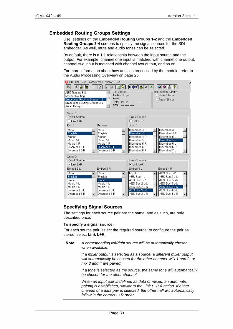
Embedded Routing Groups Settings Use settings on the Embedded Routing Groups 1-2 and the Embedded Routing Groups 3-4 screens to specify the signal sources for the SDI embedder. As well, mute and audio tones can be selected.
By default, there is a 1:1 relationship between the input source and the output. For example, channel one input is matched with channel one output, channel two input is matched with channel two output, and so on.
For more information about how audio is processed by the module, refer to the Audio Processing Overview on page 25.
Specifying Signal Sources The settings for each source pair are the same, and as such, are only described once.
To specify a signal source: For each source pair, select the required source; to configure the pair as stereo, select Link L+R.
Note: A corresponding left/right source will be automatically chosen when available.
If a mixer output is selected as a source, a different mixer output will automatically be chosen for the other channel. Mix 1 and 2, or mix 3 and 4 are paired.
If a tone is selected as the source, the same tone will automatically be chosen for the other channel.
When an input pair is defined as data or mixed, an automatic pairing is established, similar to the Link L+R function. If either channel of a data pair is selected, the other half will automatically follow in the correct L+R order.
IQMUX42 – 49 Version 2 Issue 1
Page 40
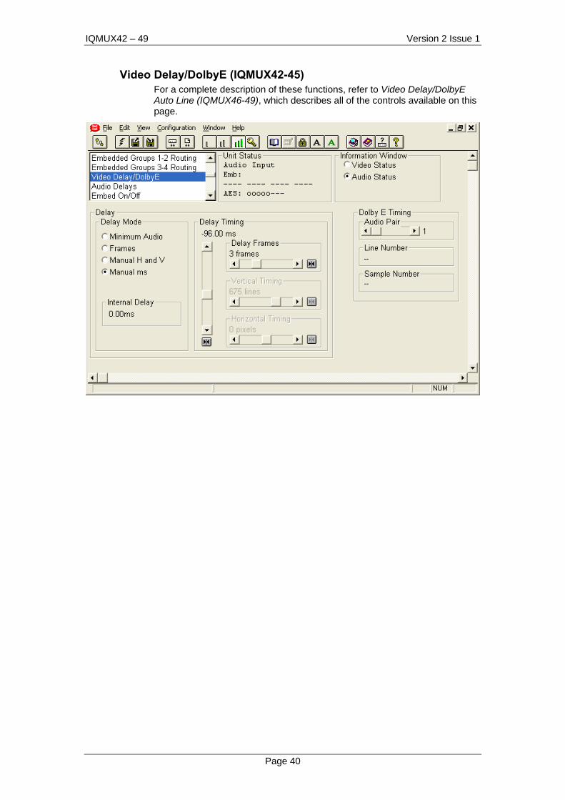
Video Delay/DolbyE (IQMUX42-45) For a complete description of these functions, refer to Video Delay/DolbyE Auto Line (IQMUX46-49), which describes all of the controls available on this page.
IQMUX42 – 49 Version 2 Issue 1
Page 41
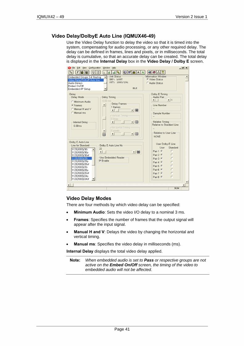
Video Delay/DolbyE Auto Line (IQMUX46-49) Use the Video Delay function to delay the video so that it is timed into the system, compensating for audio processing, or any other required delay. The delay can be defined in frames, lines and pixels, or in milliseconds. The total delay is cumulative, so that an accurate delay can be created. The total delay is displayed in the Internal Delay box in the Video Delay / Dolby E screen.
Video Delay Modes There are four methods by which video delay can be specified:
• Minimum Audio: Sets the video I/O delay to a nominal 3 ms.
• Frames: Specifies the number of frames that the output signal will appear after the input signal.
• Manual H and V: Delays the video by changing the horizontal and vertical timing.
• Manual ms: Specifies the video delay in milliseconds (ms).
Internal Delay displays the total video delay applied.
Note: When embedded audio is set to Pass or respective groups are not active on the Embed On/Off screen, the timing of the video to embedded audio will not be affected.
IQMUX42 – 49 Version 2 Issue 1
Page 42
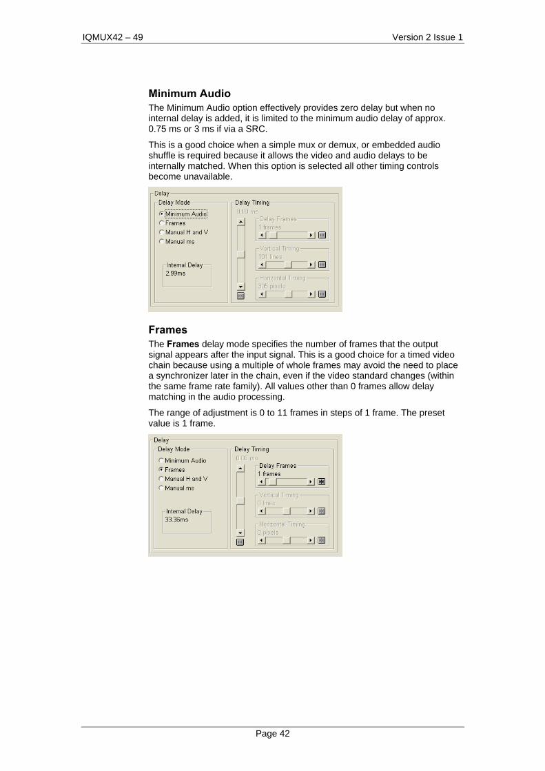
Minimum Audio The Minimum Audio option effectively provides zero delay but when no internal delay is added, it is limited to the minimum audio delay of approx. 0.75 ms or 3 ms if via a SRC.
This is a good choice when a simple mux or demux, or embedded audio shuffle is required because it allows the video and audio delays to be internally matched. When this option is selected all other timing controls become unavailable.
Frames The Frames delay mode specifies the number of frames that the output signal appears after the input signal. This is a good choice for a timed video chain because using a multiple of whole frames may avoid the need to place a synchronizer later in the chain, even if the video standard changes (within the same frame rate family). All values other than 0 frames allow delay matching in the audio processing.
The range of adjustment is 0 to 11 frames in steps of 1 frame. The preset value is 1 frame.
IQMUX42 – 49 Version 2 Issue 1
Page 43
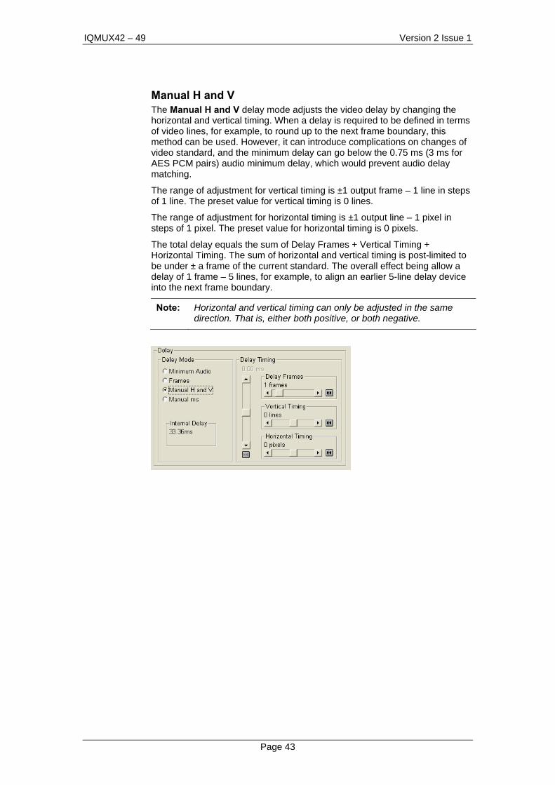
Manual H and V The Manual H and V delay mode adjusts the video delay by changing the horizontal and vertical timing. When a delay is required to be defined in terms of video lines, for example, to round up to the next frame boundary, this method can be used. However, it can introduce complications on changes of video standard, and the minimum delay can go below the 0.75 ms (3 ms for AES PCM pairs) audio minimum delay, which would prevent audio delay matching.
The range of adjustment for vertical timing is ±1 output frame – 1 line in steps of 1 line. The preset value for vertical timing is 0 lines.
The range of adjustment for horizontal timing is ±1 output line – 1 pixel in steps of 1 pixel. The preset value for horizontal timing is 0 pixels.
The total delay equals the sum of Delay Frames + Vertical Timing + Horizontal Timing. The sum of horizontal and vertical timing is post-limited to be under ± a frame of the current standard. The overall effect being allow a delay of 1 frame – 5 lines, for example, to align an earlier 5-line delay device into the next frame boundary.
Note: Horizontal and vertical timing can only be adjusted in the same direction. That is, either both positive, or both negative.
IQMUX42 – 49 Version 2 Issue 1
Page 44
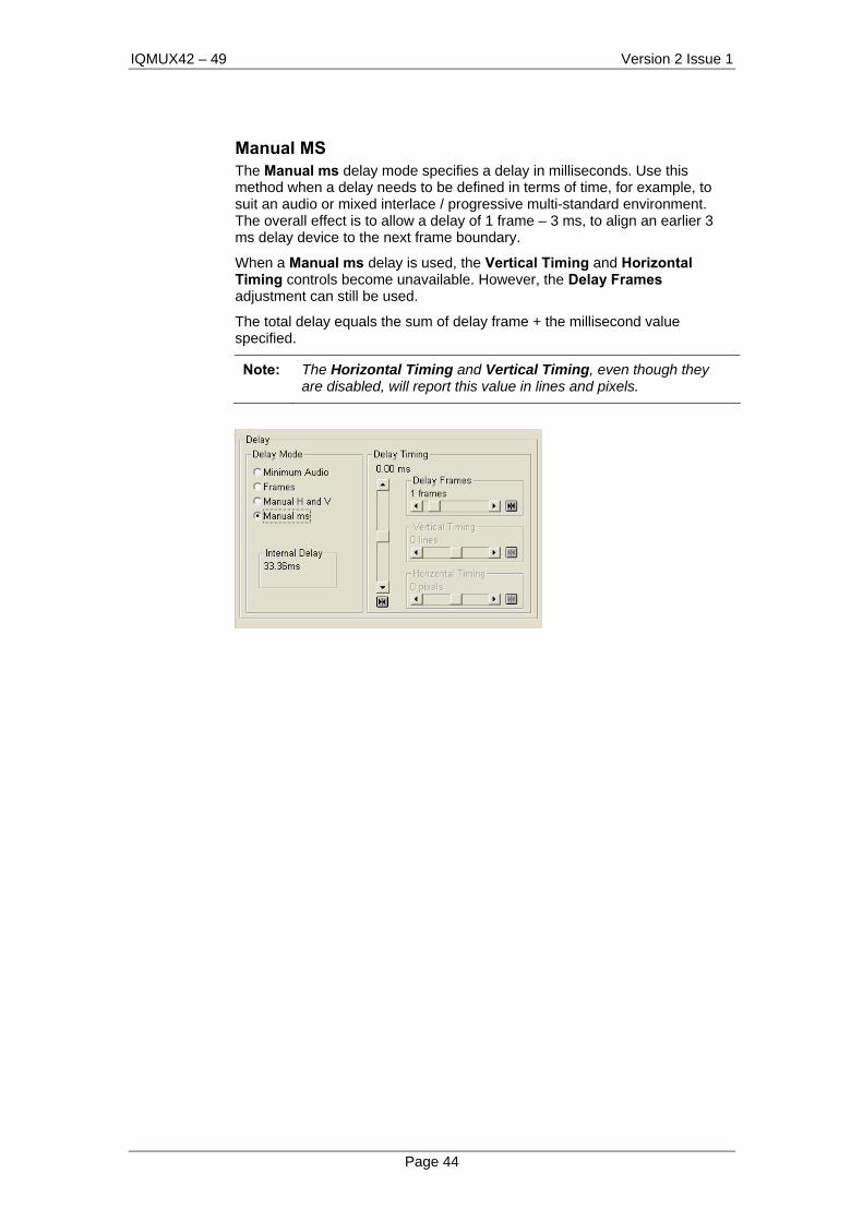
Manual MS The Manual ms delay mode specifies a delay in milliseconds. Use this method when a delay needs to be defined in terms of time, for example, to suit an audio or mixed interlace / progressive multi-standard environment. The overall effect is to allow a delay of 1 frame – 3 ms, to align an earlier 3 ms delay device to the next frame boundary.
When a Manual ms delay is used, the Vertical Timing and Horizontal Timing controls become unavailable. However, the Delay Frames adjustment can still be used.
The total delay equals the sum of delay frame + the millisecond value specified.
Note: The Horizontal Timing and Vertical Timing, even though they are disabled, will report this value in lines and pixels.
IQMUX42 – 49 Version 2 Issue 1
Page 45
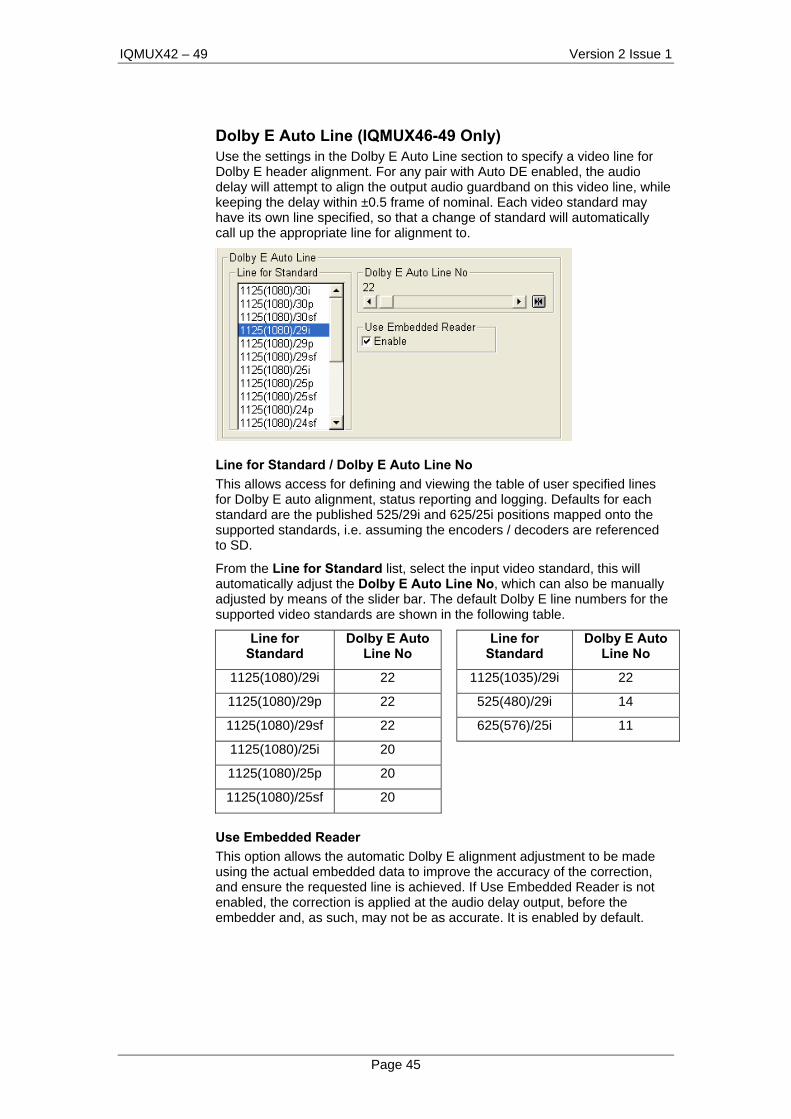
Dolby E Auto Line (IQMUX46-49 Only) Use the settings in the Dolby E Auto Line section to specify a video line for Dolby E header alignment. For any pair with Auto DE enabled, the audio delay will attempt to align the output audio guardband on this video line, while keeping the delay within ±0.5 frame of nominal. Each video standard may have its own line specified, so that a change of standard will automatically call up the appropriate line for alignment to.
Line for Standard / Dolby E Auto Line No This allows access for defining and viewing the table of user specified lines for Dolby E auto alignment, status reporting and logging. Defaults for each standard are the published 525/29i and 625/25i positions mapped onto the supported standards, i.e. assuming the encoders / decoders are referenced to SD.
From the Line for Standard list, select the input video standard, this will automatically adjust the Dolby E Auto Line No, which can also be manually adjusted by means of the slider bar. The default Dolby E line numbers for the supported video standards are shown in the following table.
Line for Standard
Dolby E Auto Line No
Line for Standard
Dolby E Auto Line No
1125(1080)/29i 22 1125(1035)/29i 22
1125(1080)/29p 22 525(480)/29i 14
1125(1080)/29sf 22 625(576)/25i 11
1125(1080)/25i 20
1125(1080)/25p 20
1125(1080)/25sf 20
Use Embedded Reader This option allows the automatic Dolby E alignment adjustment to be made using the actual embedded data to improve the accuracy of the correction, and ensure the requested line is achieved. If Use Embedded Reader is not enabled, the correction is applied at the audio delay output, before the embedder and, as such, may not be as accurate. It is enabled by default.
IQMUX42 – 49 Version 2 Issue 1
Page 46
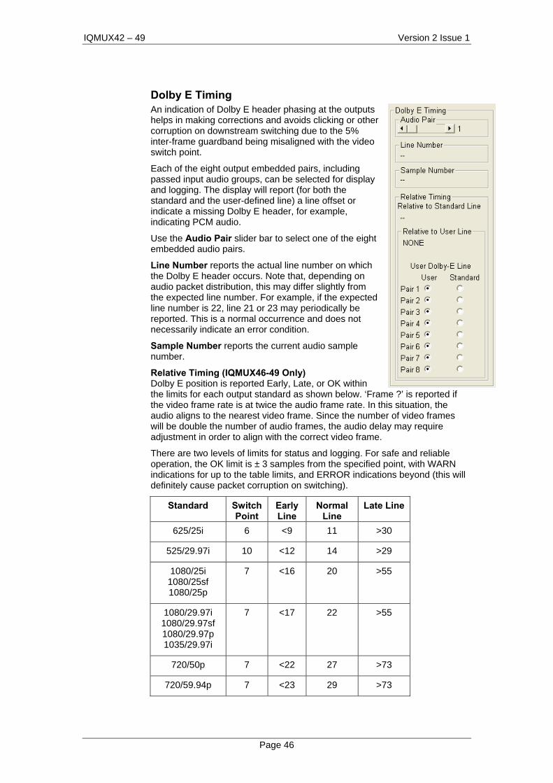
Dolby E Timing An indication of Dolby E header phasing at the outputs helps in making corrections and avoids clicking or other corruption on downstream switching due to the 5% inter-frame guardband being misaligned with the video switch point.
Each of the eight output embedded pairs, including passed input audio groups, can be selected for display and logging. The display will report (for both the standard and the user-defined line) a line offset or indicate a missing Dolby E header, for example, indicating PCM audio.
Use the Audio Pair slider bar to select one of the eight embedded audio pairs.
Line Number reports the actual line number on which the Dolby E header occurs. Note that, depending on audio packet distribution, this may differ slightly from the expected line number. For example, if the expected line number is 22, line 21 or 23 may periodically be reported. This is a normal occurrence and does not necessarily indicate an error condition.
Sample Number reports the current audio sample number.
Relative Timing (IQMUX46-49 Only) Dolby E position is reported Early, Late, or OK within the limits for each output standard as shown below. ‘Frame ?’ is reported if the video frame rate is at twice the audio frame rate. In this situation, the audio aligns to the nearest video frame. Since the number of video frames will be double the number of audio frames, the audio delay may require adjustment in order to align with the correct video frame.
There are two levels of limits for status and logging. For safe and reliable operation, the OK limit is ± 3 samples from the specified point, with WARN indications for up to the table limits, and ERROR indications beyond (this will definitely cause packet corruption on switching).
Standard Switch Point
Early Line
Normal Line
Late Line
625/25i 6 <9 11 >30
525/29.97i 10 <12 14 >29
1080/25i 1080/25sf 1080/25p
7 <16 20 >55
1080/29.97i 1080/29.97sf 1080/29.97p 1035/29.97i
7 <17 22 >55
720/50p 7 <22 27 >73
720/59.94p 7 <23 29 >73
IQMUX42 – 49 Version 2 Issue 1
Page 47
Note: All HD standards use line 7 for the frame switching line. Unsupported frame rates are: 23.98, 24, 30, 60 in i or p or sf types
User Dolby-E Line (IQMUX46-49 Only) If the Dolby E delay has been manually configured, select User next to corresponding audio pairs to specify which of the eight audio pairs will monitor the user line for status and logging. Alternatively, select Standard to monitor the standard Dolby E line.
IQMUX42 – 49 Version 2 Issue 1
Page 48
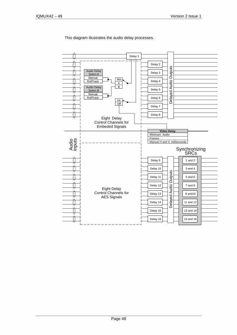
Audio Delay Settings The IQMUX42 - 49 audio delay control system comprises 16 separate delay blocks. Each block processes a pair of PCM audio channels or one non-PCM data feed. The delay blocks can be controlled by one of two composite control feeds for external adjustment, or by an internal matching delay option. Each control feed can be driven by combination of both tracking and fixed delays. Tracking delays are those that can follow a variable timing value, such as the delay through a video synchronizer.
The selection of audio delay control A or B allows audio to be timed to, or synchronized with, one of two separate timing planes. Delays can be configured such that:
• A minimum of delay is applied.
• All audio is delayed together.
• Some audio is delayed, while some is not.
• Audio pairs have differing amounts of delay applied.
The delays are SMPTE-337 data aware, and as such will attempt to track any changes during the guardbands to avoid corrupting any data packets. This limits response to changes to a rate similar to the SRC filtered case, which is entirely adequate for tracking while synchronizing video.
For each delay block then the delay can be derived from one of the following settings:
Min Effectively zero delay but when no Internal delay is added it is limited to the minimum audio delay of approx. 0.75 ms or 3 ms if via a SRC.
A The delay time for this audio pair is the value set by the Audio Delay Select-A control.
B The delay time for this audio pair is the value set by the Audio Delay Select-B control.
V Adds an audio delay equal to the unit's video Internal Delay setting when enabled.
Auto DE (MUX46- 49 Only)
When selected, the unit alters the audio delay by up to half a frame to automatically place the Dolby E header on the same line as specified by the Dolby E Auto Line No control on the Dolby E Auto Line page. RollTrack and GPI inputs must be static when contributing to delay controls using Auto DE.
IQMUX42 – 49 Version 2 Issue 1
Page 49
This diagram illustrates the audio delay processes.
Del
ayed
Aud
io O
utpu
tsD
elay
ed A
udio
Out
puts
Delay 2
Delay 10
Delay 9
Delay 3
Delay 11
Delay 4
Delay 12
Delay 5
Delay 13
Delay 6
Delay 14
Delay 7
Delay 15
Delay 8
Delay 16
Eight Delay Control Channels for
Embeded Signals
Eight Delay Control Channels for
AES Signals
Audio DelaySelect A
Audio DelaySelect B
RollTrack
RollTrack
Manual
Manual
SynchronizingSRCs
3 and 4
1 and 2
5 and 6
7 and 8
9 and10
11 and 12
13 and 14
15 and 16
Delay 1
Minimum AudioVideo Delay
Manual H and V, millisecondsFrames
Aud
ioIn
puts
MinAB
OffInt
IQMUX42 – 49 Version 2 Issue 1
Page 50
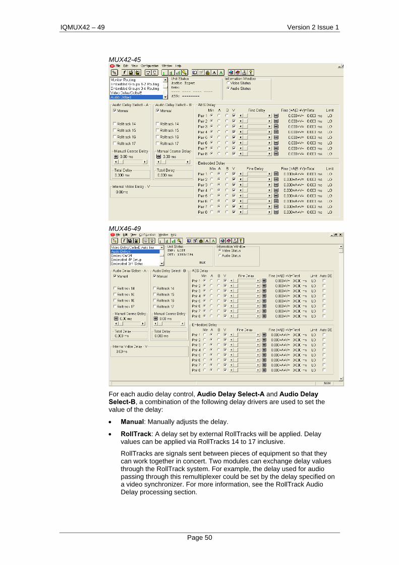
MUX42-45
MUX46-49
For each audio delay control, Audio Delay Select-A and Audio Delay Select-B, a combination of the following delay drivers are used to set the value of the delay:
• Manual: Manually adjusts the delay.
• RollTrack: A delay set by external RollTracks will be applied. Delay values can be applied via RollTracks 14 to 17 inclusive.
RollTracks are signals sent between pieces of equipment so that they can work together in concert. Two modules can exchange delay values through the RollTrack system. For example, the delay used for audio passing through this remultiplexer could be set by the delay specified on a video synchronizer. For more information, see the RollTrack Audio Delay processing section.
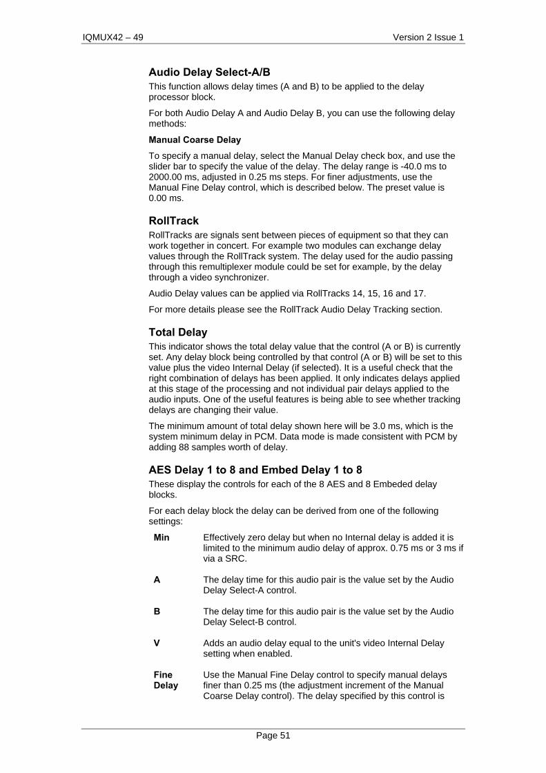
IQMUX42 – 49 Version 2 Issue 1
Page 51
Audio Delay Select-A/B This function allows delay times (A and B) to be applied to the delay processor block.
For both Audio Delay A and Audio Delay B, you can use the following delay methods:
Manual Coarse Delay
To specify a manual delay, select the Manual Delay check box, and use the slider bar to specify the value of the delay. The delay range is -40.0 ms to 2000.00 ms, adjusted in 0.25 ms steps. For finer adjustments, use the Manual Fine Delay control, which is described below. The preset value is 0.00 ms.
RollTrack RollTracks are signals sent between pieces of equipment so that they can work together in concert. For example two modules can exchange delay values through the RollTrack system. The delay used for the audio passing through this remultiplexer module could be set for example, by the delay through a video synchronizer.
Audio Delay values can be applied via RollTracks 14, 15, 16 and 17.
For more details please see the RollTrack Audio Delay Tracking section.
Total Delay This indicator shows the total delay value that the control (A or B) is currently set. Any delay block being controlled by that control (A or B) will be set to this value plus the video Internal Delay (if selected). It is a useful check that the right combination of delays has been applied. It only indicates delays applied at this stage of the processing and not individual pair delays applied to the audio inputs. One of the useful features is being able to see whether tracking delays are changing their value.
The minimum amount of total delay shown here will be 3.0 ms, which is the system minimum delay in PCM. Data mode is made consistent with PCM by adding 88 samples worth of delay.
AES Delay 1 to 8 and Embed Delay 1 to 8 These display the controls for each of the 8 AES and 8 Embeded delay blocks.
For each delay block the delay can be derived from one of the following settings:
Min Effectively zero delay but when no Internal delay is added it is limited to the minimum audio delay of approx. 0.75 ms or 3 ms if via a SRC.
A The delay time for this audio pair is the value set by the Audio Delay Select-A control.
B The delay time for this audio pair is the value set by the Audio Delay Select-B control.
V Adds an audio delay equal to the unit's video Internal Delay setting when enabled.
Fine Delay
Use the Manual Fine Delay control to specify manual delays finer than 0.25 ms (the adjustment increment of the Manual Coarse Delay control). The delay specified by this control is
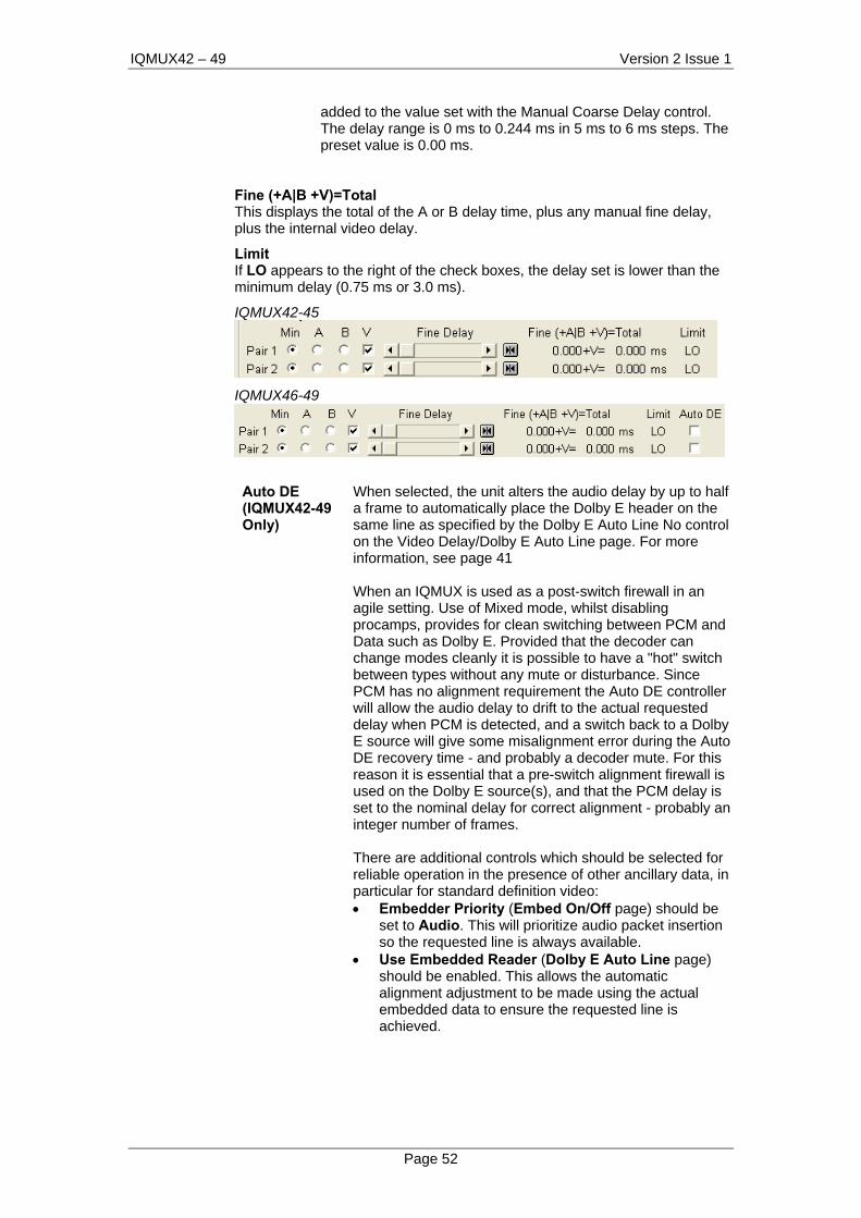
IQMUX42 – 49 Version 2 Issue 1
Page 52
added to the value set with the Manual Coarse Delay control. The delay range is 0 ms to 0.244 ms in 5 ms to 6 ms steps. The preset value is 0.00 ms.
Fine (+A|B +V)=Total This displays the total of the A or B delay time, plus any manual fine delay, plus the internal video delay.
Limit If LO appears to the right of the check boxes, the delay set is lower than the minimum delay (0.75 ms or 3.0 ms).
IQMUX42-45
IQMUX46-49
Auto DE (IQMUX42-49 Only)
When selected, the unit alters the audio delay by up to half a frame to automatically place the Dolby E header on the same line as specified by the Dolby E Auto Line No control on the Video Delay/Dolby E Auto Line page. For more information, see page 41 When an IQMUX is used as a post-switch firewall in an agile setting. Use of Mixed mode, whilst disabling procamps, provides for clean switching between PCM and Data such as Dolby E. Provided that the decoder can change modes cleanly it is possible to have a "hot" switch between types without any mute or disturbance. Since PCM has no alignment requirement the Auto DE controller will allow the audio delay to drift to the actual requested delay when PCM is detected, and a switch back to a Dolby E source will give some misalignment error during the Auto DE recovery time - and probably a decoder mute. For this reason it is essential that a pre-switch alignment firewall is used on the Dolby E source(s), and that the PCM delay is set to the nominal delay for correct alignment - probably an integer number of frames. There are additional controls which should be selected for reliable operation in the presence of other ancillary data, in particular for standard definition video: • Embedder Priority (Embed On/Off page) should be
set to Audio. This will prioritize audio packet insertion so the requested line is always available.
• Use Embedded Reader (Dolby E Auto Line page) should be enabled. This allows the automatic alignment adjustment to be made using the actual embedded data to ensure the requested line is achieved.
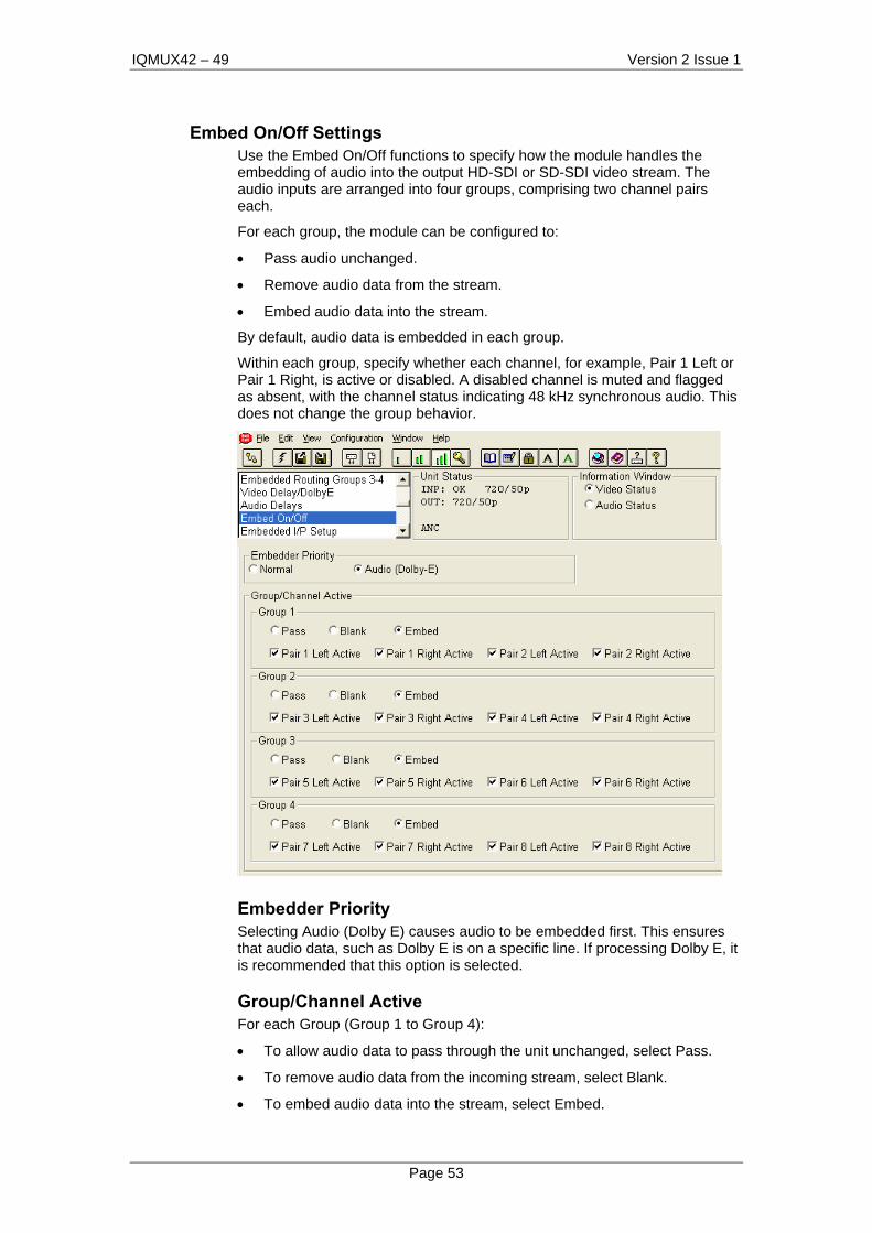
IQMUX42 – 49 Version 2 Issue 1
Page 53
Embed On/Off Settings Use the Embed On/Off functions to specify how the module handles the embedding of audio into the output HD-SDI or SD-SDI video stream. The audio inputs are arranged into four groups, comprising two channel pairs each.
For each group, the module can be configured to:
• Pass audio unchanged.
• Remove audio data from the stream.
• Embed audio data into the stream.
By default, audio data is embedded in each group.
Within each group, specify whether each channel, for example, Pair 1 Left or Pair 1 Right, is active or disabled. A disabled channel is muted and flagged as absent, with the channel status indicating 48 kHz synchronous audio. This does not change the group behavior.
Embedder Priority Selecting Audio (Dolby E) causes audio to be embedded first. This ensures that audio data, such as Dolby E is on a specific line. If processing Dolby E, it is recommended that this option is selected.
Group/Channel Active For each Group (Group 1 to Group 4):
• To allow audio data to pass through the unit unchanged, select Pass.
• To remove audio data from the incoming stream, select Blank.
• To embed audio data into the stream, select Embed.
IQMUX42 – 49 Version 2 Issue 1
Page 54
For each channel within each group:
• To activate the channel, select the corresponding check box.
• To disable the channel, clear the corresponding check box.
For more information about Audio Embedding, see Ancillary Passing and Audio Embedding on page 147.
Embedded I/P Setup Use the Embedded I/P Setup screen to specify whether an input audio pair should be treated as:
• PCM audio
• Data
• Mixed mode
This screen also allows the names of the disembedded audio inputs to be changed from the default names (Disembed 1 etc.).
The input embedded audio must be sampled at 48 kHz Up to 20 bit resolution is supported in SD video standards, and up to 24 bit resolution is supported in all HD video standards.
The mixer, routing, and ProcAmp functions are channel-based and can pass or process on either channel. However, audio delays are pair-based and it is not possible to apply a different delay to the two channels of an input audio pair.
Embedded audio is a pair based system. This means that they carry the sound as two channels and it is not possible to carry just one channel. Of course, the unit can pass and process either channel as well as both. This is because the module is channel-based internally. When an embedded feed is used to carry non-PCM data then the whole data space is allocated to that function. In this mode the feed has to be treated together, it has to be treated as the equivalent of a pair. For example a non PCM feed at the input will occupy the same space as two audio channels and must be passed to the output as two channels of data.
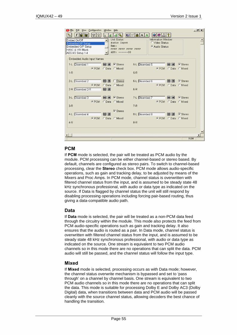
IQMUX42 – 49 Version 2 Issue 1
Page 55
PCM If PCM mode is selected, the pair will be treated as PCM audio by the module. PCM processing can be either channel-based or stereo based. By default, channels are configured as stereo pairs. To switch to channel-based processing, clear the Stereo check box. PCM mode allows audio-specific operations, such as gain and tracking delay, to be adjusted by means of the Mixers and Proc Amps. In PCM mode, channel status is overwritten with filtered channel status from the input, and is assumed to be steady state 48 kHz synchronous professional, with audio or data type as indicated on the source. If Data is flagged by channel status the unit will still respond by disabling processing operations including forcing pair-based routing, thus giving a data-compatible audio path.
Data If Data mode is selected, the pair will be treated as a non-PCM data feed through the circuitry within the module. This mode also protects the feed from PCM audio-specific operations such as gain and tracking delay. It also ensures that the audio is routed as a pair. In Data mode, channel status is overwritten with filtered channel status from the input, and is assumed to be steady state 48 kHz synchronous professional, with audio or data type as indicated on the source. One stream is equivalent to two PCM audio channels so in this mode there are no operations that can split the data. PCM audio will still be passed, and the channel status will follow the input type.
Mixed If Mixed mode is selected, processing occurs as with Data mode; however, the channel status overwrite mechanism is bypassed and set to ‘pass through’ on a channel by channel basis. One stream is equivalent to two PCM audio channels so in this mode there are no operations that can split the data. This mode is suitable for processing Dolby E and Dolby AC3 (Dolby Digital) data, when transitions between data and PCM audio will be passed cleanly with the source channel status, allowing decoders the best chance of handling the transition.
IQMUX42 – 49 Version 2 Issue 1
Page 56
Embedded Audio Input Names By default, channels are designated as stereo pairs. To name each channel individually, clear the Stereo check box.
To change a disembedded audio input name: • Type the new name in the field, and click the arrow button .
• To return to the default name, click the preset button .
Note: When a channel is designated as a stereo signal, the corresponding left/right channel does not appear.
Names are stored in the Memory function so that a new set of names can be recalled by memory.
These names are used in the lists for the following functions:
• Audio Mixer Inputs
• AES Routing
• Monitoring Routing
• Embedded Routing
• Embedded Input Setup
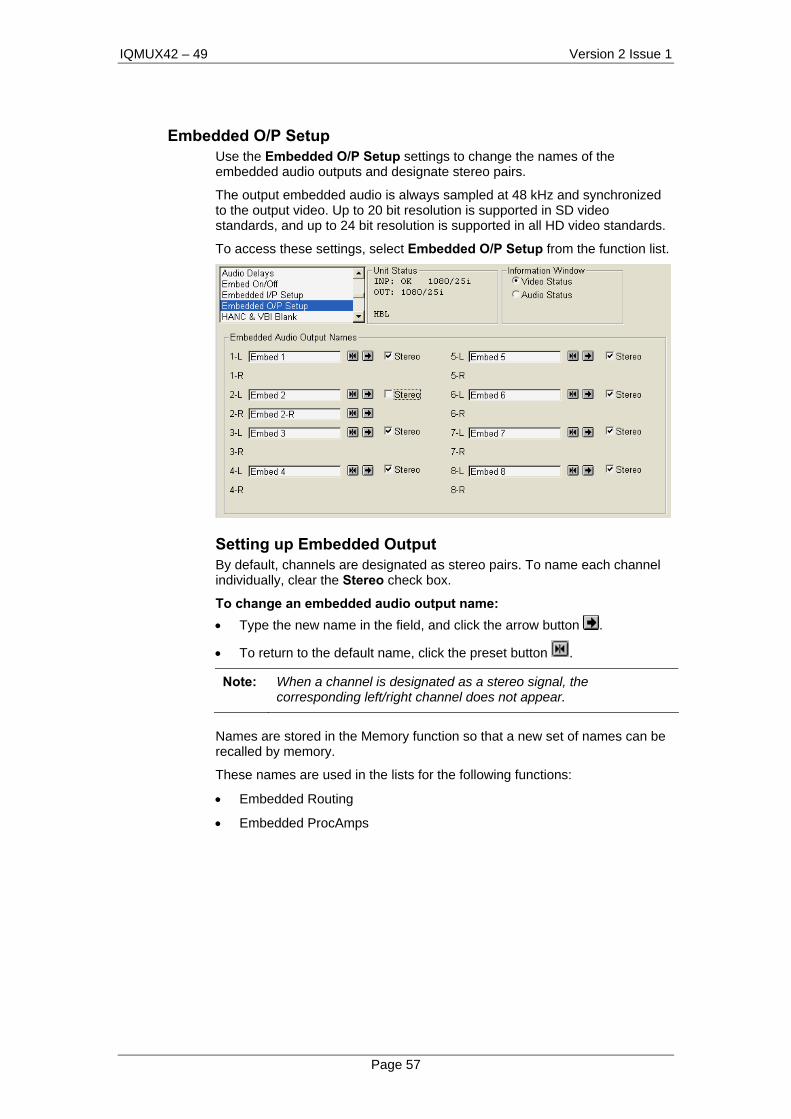
IQMUX42 – 49 Version 2 Issue 1
Page 57
Embedded O/P Setup Use the Embedded O/P Setup settings to change the names of the embedded audio outputs and designate stereo pairs.
The output embedded audio is always sampled at 48 kHz and synchronized to the output video. Up to 20 bit resolution is supported in SD video standards, and up to 24 bit resolution is supported in all HD video standards.
To access these settings, select Embedded O/P Setup from the function list.
Setting up Embedded Output By default, channels are designated as stereo pairs. To name each channel individually, clear the Stereo check box.
To change an embedded audio output name: • Type the new name in the field, and click the arrow button .
• To return to the default name, click the preset button .
Note: When a channel is designated as a stereo signal, the corresponding left/right channel does not appear.
Names are stored in the Memory function so that a new set of names can be recalled by memory.
These names are used in the lists for the following functions:
• Embedded Routing
• Embedded ProcAmps
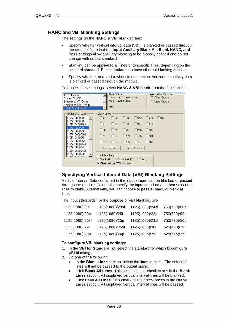
IQMUX42 – 49 Version 2 Issue 1
Page 58
HANC and VBI Blanking Settings The settings on the HANC & VBI blank screen:
• Specify whether vertical interval data (VBI), is blanked or passed through the module. Note that the Input Ancillary Blank All, Blank HANC, and Pass settings allow ancillary blanking to be globally defined and do not change with output standard.
• Blanking can be applied to all lines or to specific lines, depending on the selected standard. Each standard can have different blanking applied.
• Specify whether, and under what circumstances, horizontal ancillary data is blanked or passed through the module.
To access these settings, select HANC & VBI blank from the function list.
Specifying Vertical Interval Data (VBI) Blanking Settings Vertical Interval Data contained in the input stream can be blanked or passed through the module. To do this, specify the input standard and then select the lines to blank. Alternatively, you can choose to pass all lines, or blank all lines.
The input standards, for the purpose of VBI blanking, are:
1125(1080)/30i 1125(1080)/29sf 1125(1080)/24sf 750(720)/60p
1125(1080)/30p 1125(1080)/25i 1125(1080)/23p 750(720)/59p
1125(1080)/30sf 1125(1080)/25p 1125(1080)/23sf 750(720)/50p
1125(1080)/29i 1125(1080)/25sf 1125(1035)/30i 525(480)/29i
1125(1080)/29p 1125(1080)/24p 1125(1035)/29i 625(576)/25i
To configure VBI blanking settings: 1. In the VBI for Standard list, select the standard for which to configure
VBI blanking. 2. Do one of the following:
• In the Blank Lines section, select the lines to blank. The selected lines will not be passed to the output signal.
• Click Blank All Lines. This selects all the check boxes in the Blank Lines section. All displayed vertical interval lines will be blanked.
• Click Pass All Lines. This clears all the check boxes in the Blank Lines section. All displayed vertical interval lines will be passed.
IQMUX42 – 49 Version 2 Issue 1
Page 59
Specifying Horizontal Ancillary Data (HANC) Blanking Settings The Input Ancillary Controls specify whether to:
• Remove all ancillary data.
• Remove only horizontal ancillary data.
• Allow ancillary data to pass unaltered.
• Remove all ancillary data, if the input signal fails to match the output standard.
Note: Embedded audio (as enabled for embedding) and EDH controls are not affected by these controls.
To remove all ancillary data: • In the Input Ancillary section, select Blank All.
This setting overrides the VBI Blank Lines control.
To remove only horizontal ancillary data (HANC); • In the Input Ancillary section, select Blank HANC.
To allow ancillary data to pass unaltered: • In the Input Ancillary section, select Pass.
When Pass is selected, pass-through operations will not alter audio packets for groups that are not selected for embedding.
To remove all ancillary data if the input signal fails to match the output standard: • In the Input Ancillary section, select Blank All on STD mismatch.
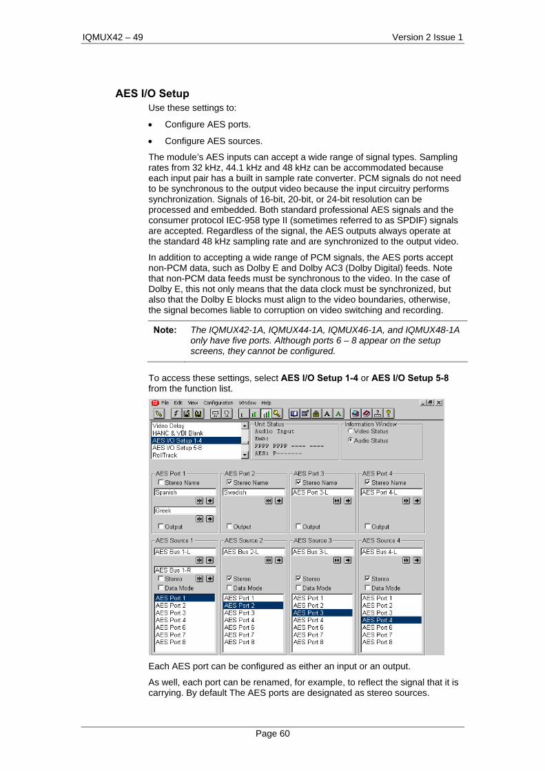
IQMUX42 – 49 Version 2 Issue 1
Page 60
AES I/O Setup Use these settings to:
• Configure AES ports.
• Configure AES sources.
The module’s AES inputs can accept a wide range of signal types. Sampling rates from 32 kHz, 44.1 kHz and 48 kHz can be accommodated because each input pair has a built in sample rate converter. PCM signals do not need to be synchronous to the output video because the input circuitry performs synchronization. Signals of 16-bit, 20-bit, or 24-bit resolution can be processed and embedded. Both standard professional AES signals and the consumer protocol IEC-958 type II (sometimes referred to as SPDIF) signals are accepted. Regardless of the signal, the AES outputs always operate at the standard 48 kHz sampling rate and are synchronized to the output video.
In addition to accepting a wide range of PCM signals, the AES ports accept non-PCM data, such as Dolby E and Dolby AC3 (Dolby Digital) feeds. Note that non-PCM data feeds must be synchronous to the video. In the case of Dolby E, this not only means that the data clock must be synchronized, but also that the Dolby E blocks must align to the video boundaries, otherwise, the signal becomes liable to corruption on video switching and recording.
Note: The IQMUX42-1A, IQMUX44-1A, IQMUX46-1A, and IQMUX48-1A only have five ports. Although ports 6 – 8 appear on the setup screens, they cannot be configured.
To access these settings, select AES I/O Setup 1-4 or AES I/O Setup 5-8 from the function list.
Each AES port can be configured as either an input or an output.
As well, each port can be renamed, for example, to reflect the signal that it is carrying. By default The AES ports are designated as stereo sources.
IQMUX42 – 49 Version 2 Issue 1
Page 61
However, each channel can be named individually. These names are used for the following functions:
• AES ProcAmp
• AES Routing
To specify whether the port is an input or an output: • To designate the port as an output, select the Output check box.
• To designate the port as an input, clear the Output check box.
When a port is configured as an input, the AES port appears in the router listings at the bottom of the screen. This can be used to specify a different port routing if necessary.
To rename a port: • Type the name of the port in the text field and click the arrow button .
To name each channel individually, clear the Stereo check box.
To return the port to its default name, click the preset button .
Configure each AES port to handle PCM audio, non-PCM data, or both. This selection is essential if Dolby E or Dolby AC3 (Dolby Digital) is being passed through an AES port.
Note: In data and mixed modes, the Sample Rate Converter (SRC) is bypassed.
AES channel status (audio/non-audio) is used to detect non-PCM.
PCM If PCM mode is selected, the pair will be treated as PCM audio by the module. PCM processing can be either channel-based or stereo based. By default, channels are configured as stereo pairs. To switch to channel-based processing, clear the Stereo check box. PCM mode allows audio-specific operations, such as gain and tracking delay, to be adjusted by means of the Mixers and Proc Amps. In PCM mode, channel status is overwritten with filtered channel status from the input, and is assumed to be steady state 48 kHz synchronous professional, with audio or data type as indicated on the source. If Data is flagged by channel status the unit will still respond by disabling processing operations including sample rate conversion, and forcing pair-based routing, thus giving a data-compatible audio path.
Data If Data mode is selected, the pair will be treated as a non-PCM data feed through the circuitry within the module. This mode also protects the feed from PCM audio-specific operations such as gain and tracking delay. It also ensures that the audio is routed as a pair. In Data mode, channel status is overwritten with filtered channel status from the input, and is assumed to be steady state 48 kHz synchronous professional, with audio or data type as indicated on the source. One stream is equivalent to two PCM audio channels so in this mode there are no operations that can split the data. PCM audio will still be passed, and the channel status will follow the input type.
Mixed If Mixed mode is selected, processing occurs as with Data mode; however, the channel status overwrite mechanism is bypassed and set to ‘pass through’ on a channel by channel basis. One stream is equivalent to two PCM audio channels so in this mode there are no operations that can split the data. This mode is suitable for processing Dolby E and Dolby AC3 (Dolby
IQMUX42 – 49 Version 2 Issue 1
Page 62
Digital) data, when transitions between data and PCM audio will be passed cleanly with the source channel status, allowing decoders the best chance of handling the transition.
As well, each source can be renamed. By default, the AES sources are designated as stereo sources. However, each channel can be named individually. These names are used for the following functions:
• Audio Mixer inputs
• AES Routing
• Monitor Routing
• Embedded Routing.
To rename a source: • Type the name of the source in the text field and click the arrow
button .
To name each channel individually, clear the Stereo check box.
To return the source to its default name, click the preset button .
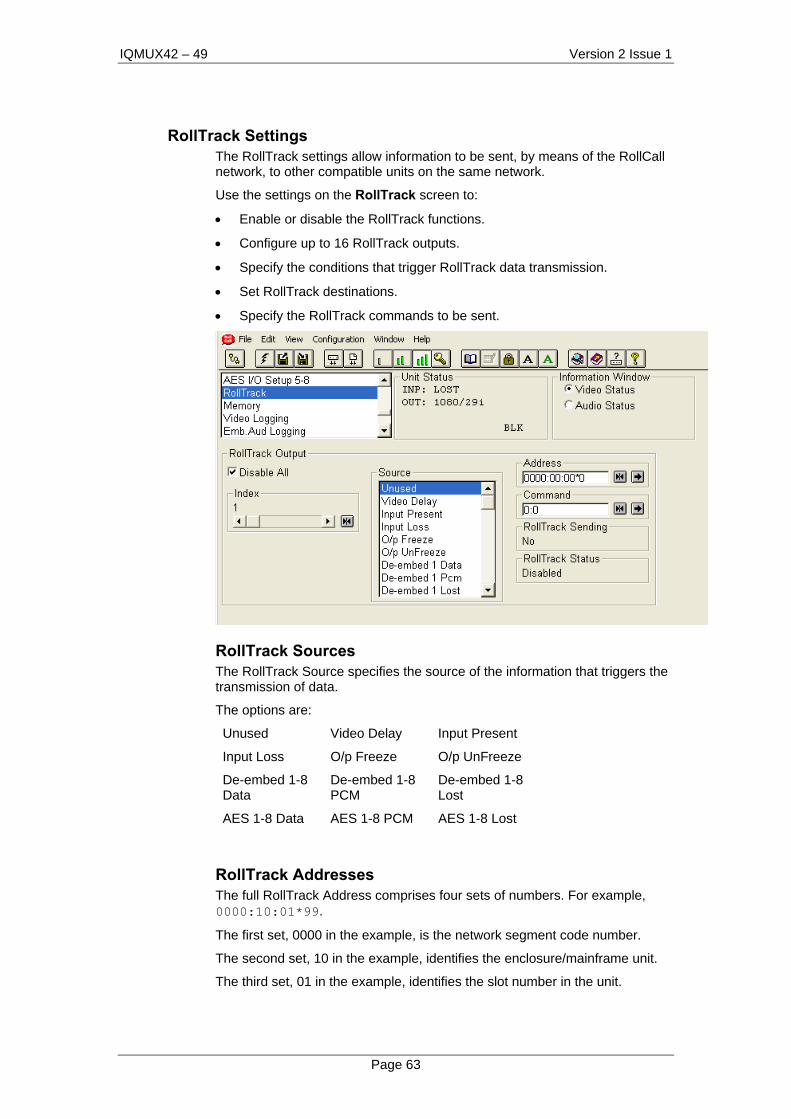
IQMUX42 – 49 Version 2 Issue 1
Page 63
RollTrack Settings The RollTrack settings allow information to be sent, by means of the RollCall network, to other compatible units on the same network.
Use the settings on the RollTrack screen to:
• Enable or disable the RollTrack functions.
• Configure up to 16 RollTrack outputs.
• Specify the conditions that trigger RollTrack data transmission.
• Set RollTrack destinations.
• Specify the RollTrack commands to be sent.
RollTrack Sources The RollTrack Source specifies the source of the information that triggers the transmission of data.
The options are:
Unused Video Delay Input Present
Input Loss O/p Freeze O/p UnFreeze
De-embed 1-8 Data
De-embed 1-8 PCM
De-embed 1-8 Lost
AES 1-8 Data AES 1-8 PCM AES 1-8 Lost
RollTrack Addresses The full RollTrack Address comprises four sets of numbers. For example, 0000:10:01*99.
The first set, 0000 in the example, is the network segment code number.
The second set, 10 in the example, identifies the enclosure/mainframe unit.
The third set, 01 in the example, identifies the slot number in the unit.
IQMUX42 – 49 Version 2 Issue 1
Page 64
The fourth set, 99 in the example, is a user-configured number that uniquely identifies the destination unit in a multi-unit system. This ensures that only the correct unit responds to commands. If left at 00, an incorrectly fitted unit may respond inappropriately.
RollTrack Commands Each RollTrack command comprises two sets of numbers, for example, 33039:3.
The first set, 33039 in the example, is the RollTrack command number, which identifies the command.
The second set, 3 in the example, is the value that is sent with the command.
Using RollTracks To enable or disable RollTrack functions: • To enable the RollTrack functions, clear the Disable All check box.
• To disable RollTrack functions, select the Disable All check box.
To configure a RollTrack action: 1. Select the Index number. This identifies the RollTrack action being
configured. Up to 16 RollTrack actions can be created. 2. From the Source list, select the source of the information that will trigger
RollTrack transmission. 3. Enter the RollTrack Address and click the arrow button . To return the
address to its default value, click the preset button . 4. Enter the RollTrack Command and click the arrow button . To return
the value to its default, click the preset button .
Viewing RollTrack Information RollTrack Sending and RollTrack Status display information about the status of RollTracks.
RollTrack Sending displays the information when the unit is actively sending a RollTrack command:
• String: A string value is being sent.
• Number: A number value is being sent.
• No: The command is not being sent.
• Yes: The command is being sent.
• Internal Type Error: Inconsistent behavior. Contact your local Snell & Wilcox agent.
RollTrack Status displays the status of the currently selected RollTrack Index:
• OK: RollTrack message sent and received OK.
• Unknown: RollTrack message has been sent but has not yet completed.
• Timeout: RollTrack message sent, but acknowledgement not received. This could be because the destination unit is not at the specified location.
• Bad: RollTrack message has not been sent correctly, acknowledged at the destination unit. This could be because the destination unit is not of the type specified.
• Disabled: RollTrack sending is disabled.
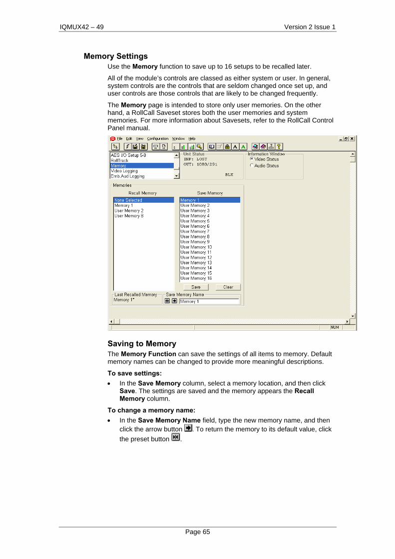
IQMUX42 – 49 Version 2 Issue 1
Page 65
Memory Settings Use the Memory function to save up to 16 setups to be recalled later.
All of the module’s controls are classed as either system or user. In general, system controls are the controls that are seldom changed once set up, and user controls are those controls that are likely to be changed frequently.
The Memory page is intended to store only user memories. On the other hand, a RollCall Saveset stores both the user memories and system memories. For more information about Savesets, refer to the RollCall Control Panel manual.
Saving to Memory The Memory Function can save the settings of all items to memory. Default memory names can be changed to provide more meaningful descriptions.
To save settings: • In the Save Memory column, select a memory location, and then click
Save. The settings are saved and the memory appears the Recall Memory column.
To change a memory name: • In the Save Memory Name field, type the new memory name, and then
click the arrow button . To return the memory to its default value, click the preset button .
IQMUX42 – 49 Version 2 Issue 1
Page 66
Recalling Memory Use the Recall Memory function to recall the settings saved in a memory location. Last Recalled Memory displays the most recently recalled memory.
An asterisk (*) appears after the last recalled memory name if adjustments have been made to any of the settings after it has been recalled.
If no memory choice has been made, or if the previous choice has been invalidated (because of a control change), None Selected is displayed.
To recall a memory: • In the Recall Memory column, select the memory to recall. The recalled
settings will be applied and the memory name will appear in the Last Recalled Memory section.
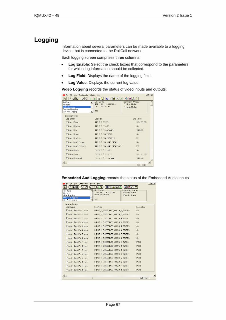
IQMUX42 – 49 Version 2 Issue 1
Page 67
Logging Information about several parameters can be made available to a logging device that is connected to the RollCall network.
Each logging screen comprises three columns:
• Log Enable: Select the check boxes that correspond to the parameters for which log information should be collected.
• Log Field: Displays the name of the logging field.
• Log Value: Displays the current log value.
Video Logging records the status of video inputs and outputs.
Embedded Aud Logging records the status of the Embedded Audio inputs.
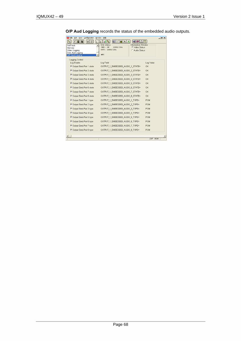
IQMUX42 – 49 Version 2 Issue 1
Page 68
O/P Aud Logging records the status of the embedded audio outputs.
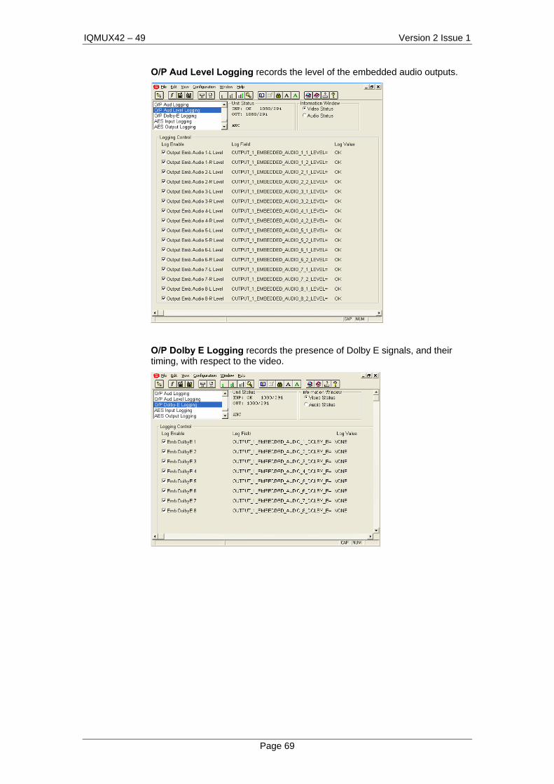
IQMUX42 – 49 Version 2 Issue 1
Page 69
O/P Aud Level Logging records the level of the embedded audio outputs.
O/P Dolby E Logging records the presence of Dolby E signals, and their timing, with respect to the video.
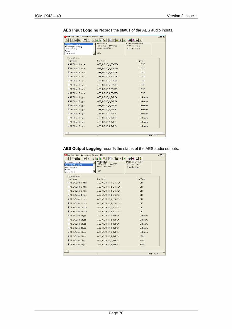
IQMUX42 – 49 Version 2 Issue 1
Page 70
AES Input Logging records the status of the AES audio inputs.
AES Output Logging records the status of the AES audio outputs.
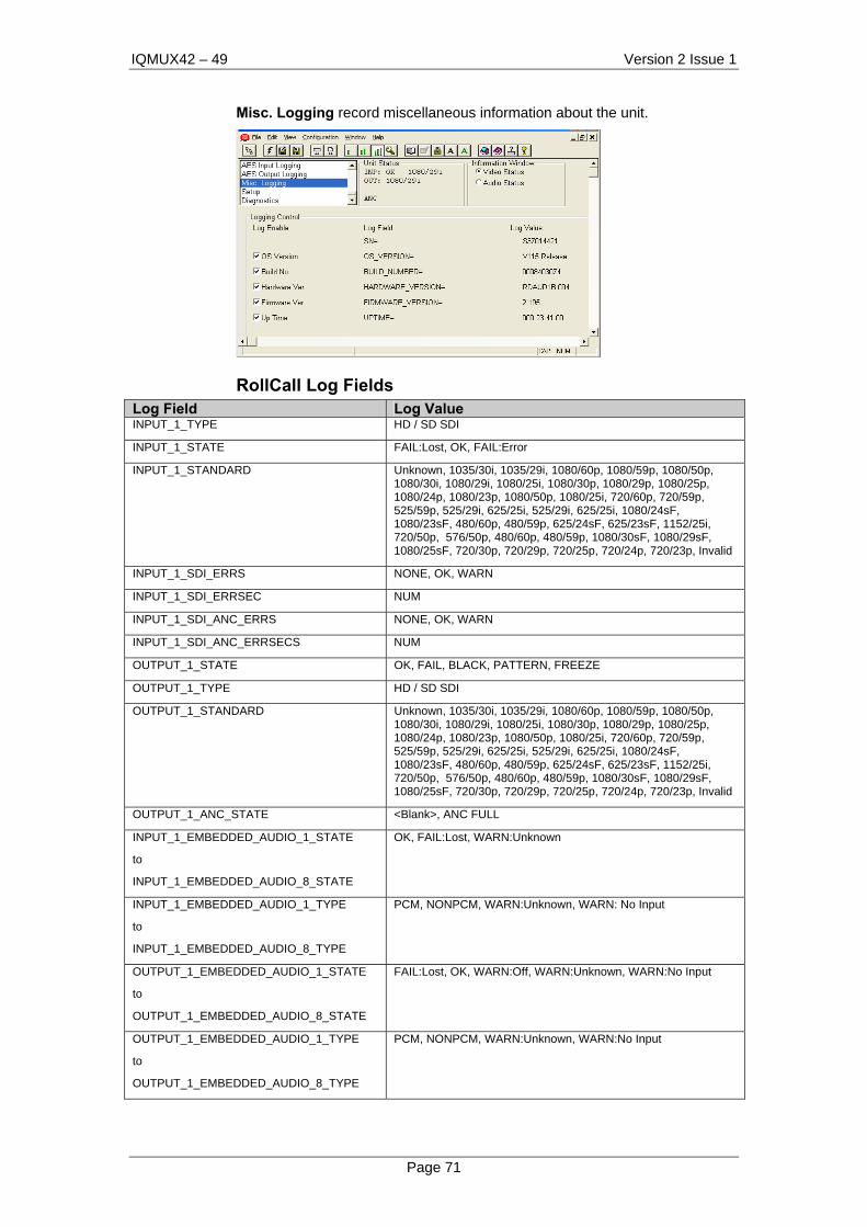
IQMUX42 – 49 Version 2 Issue 1
Page 71
Misc. Logging record miscellaneous information about the unit.
RollCall Log Fields Log Field Log Value INPUT_1_TYPE HD / SD SDI
INPUT_1_STATE FAIL:Lost, OK, FAIL:Error
INPUT_1_STANDARD Unknown, 1035/30i, 1035/29i, 1080/60p, 1080/59p, 1080/50p, 1080/30i, 1080/29i, 1080/25i, 1080/30p, 1080/29p, 1080/25p, 1080/24p, 1080/23p, 1080/50p, 1080/25i, 720/60p, 720/59p, 525/59p, 525/29i, 625/25i, 525/29i, 625/25i, 1080/24sF, 1080/23sF, 480/60p, 480/59p, 625/24sF, 625/23sF, 1152/25i, 720/50p, 576/50p, 480/60p, 480/59p, 1080/30sF, 1080/29sF, 1080/25sF, 720/30p, 720/29p, 720/25p, 720/24p, 720/23p, Invalid
INPUT_1_SDI_ERRS NONE, OK, WARN
INPUT_1_SDI_ERRSEC NUM
INPUT_1_SDI_ANC_ERRS NONE, OK, WARN
INPUT_1_SDI_ANC_ERRSECS NUM
OUTPUT_1_STATE OK, FAIL, BLACK, PATTERN, FREEZE
OUTPUT_1_TYPE HD / SD SDI
OUTPUT_1_STANDARD Unknown, 1035/30i, 1035/29i, 1080/60p, 1080/59p, 1080/50p, 1080/30i, 1080/29i, 1080/25i, 1080/30p, 1080/29p, 1080/25p, 1080/24p, 1080/23p, 1080/50p, 1080/25i, 720/60p, 720/59p, 525/59p, 525/29i, 625/25i, 525/29i, 625/25i, 1080/24sF, 1080/23sF, 480/60p, 480/59p, 625/24sF, 625/23sF, 1152/25i, 720/50p, 576/50p, 480/60p, 480/59p, 1080/30sF, 1080/29sF, 1080/25sF, 720/30p, 720/29p, 720/25p, 720/24p, 720/23p, Invalid
OUTPUT_1_ANC_STATE <Blank>, ANC FULL
INPUT_1_EMBEDDED_AUDIO_1_STATE
to
INPUT_1_EMBEDDED_AUDIO_8_STATE
OK, FAIL:Lost, WARN:Unknown
INPUT_1_EMBEDDED_AUDIO_1_TYPE
to
INPUT_1_EMBEDDED_AUDIO_8_TYPE
PCM, NONPCM, WARN:Unknown, WARN: No Input
OUTPUT_1_EMBEDDED_AUDIO_1_STATE
to
OUTPUT_1_EMBEDDED_AUDIO_8_STATE
FAIL:Lost, OK, WARN:Off, WARN:Unknown, WARN:No Input
OUTPUT_1_EMBEDDED_AUDIO_1_TYPE
to
OUTPUT_1_EMBEDDED_AUDIO_8_TYPE
PCM, NONPCM, WARN:Unknown, WARN:No Input
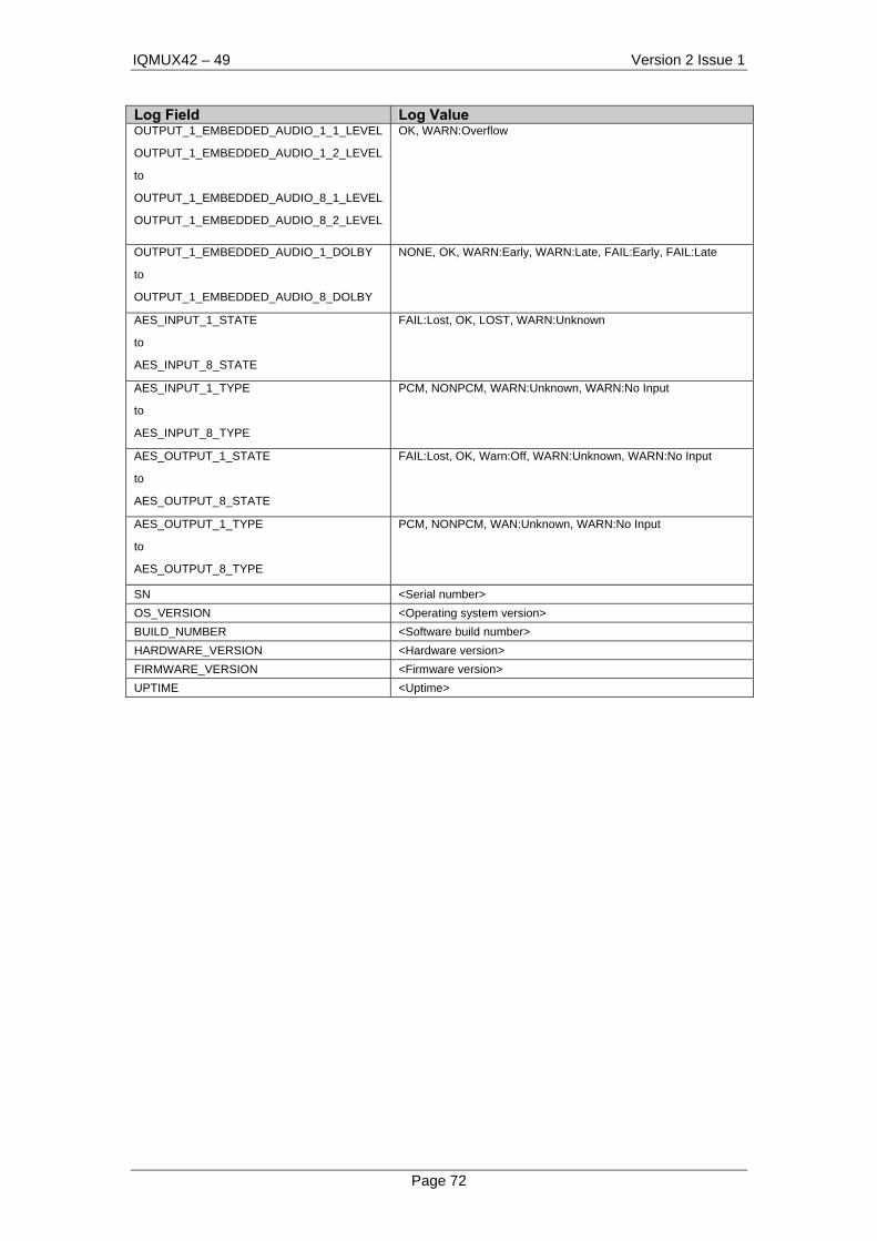
IQMUX42 – 49 Version 2 Issue 1
Page 72
Log Field Log Value OUTPUT_1_EMBEDDED_AUDIO_1_1_LEVEL
OUTPUT_1_EMBEDDED_AUDIO_1_2_LEVEL
to
OUTPUT_1_EMBEDDED_AUDIO_8_1_LEVEL
OUTPUT_1_EMBEDDED_AUDIO_8_2_LEVEL
OK, WARN:Overflow
OUTPUT_1_EMBEDDED_AUDIO_1_DOLBY
to
OUTPUT_1_EMBEDDED_AUDIO_8_DOLBY
NONE, OK, WARN:Early, WARN:Late, FAIL:Early, FAIL:Late
AES_INPUT_1_STATE
to
AES_INPUT_8_STATE
FAIL:Lost, OK, LOST, WARN:Unknown
AES_INPUT_1_TYPE
to
AES_INPUT_8_TYPE
PCM, NONPCM, WARN:Unknown, WARN:No Input
AES_OUTPUT_1_STATE
to
AES_OUTPUT_8_STATE
FAIL:Lost, OK, Warn:Off, WARN:Unknown, WARN:No Input
AES_OUTPUT_1_TYPE
to
AES_OUTPUT_8_TYPE
PCM, NONPCM, WAN:Unknown, WARN:No Input
SN <Serial number> OS_VERSION <Operating system version> BUILD_NUMBER <Software build number> HARDWARE_VERSION <Hardware version> FIRMWARE_VERSION <Firmware version> UPTIME <Uptime>
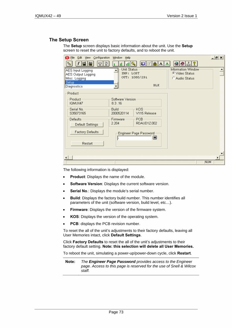
IQMUX42 – 49 Version 2 Issue 1
Page 73
The Setup Screen The Setup screen displays basic information about the unit. Use the Setup screen to reset the unit to factory defaults, and to reboot the unit.
The following information is displayed:
• Product: Displays the name of the module.
• Software Version: Displays the current software version.
• Serial No.: Displays the module’s serial number.
• Build: Displays the factory build number. This number identifies all parameters of the unit (software version, build level, etc…).
• Firmware: Displays the version of the firmware system.
• KOS: Displays the version of the operating system.
• PCB: displays the PCB revision number.
To reset the all of the unit’s adjustments to their factory defaults, leaving all User Memories intact, click Default Settings.
Click Factory Defaults to reset the all of the unit’s adjustments to their factory default setting. Note: this selection will delete all User Memories.
To reboot the unit, simulating a power-up/power-down cycle, click Restart.
Note: The Engineer Page Password provides access to the Engineer page. Access to this page is reserved for the use of Snell & Wilcox staff.
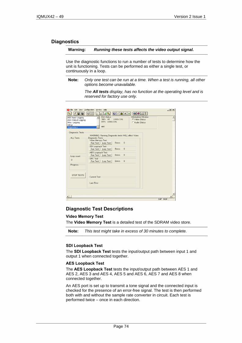
IQMUX42 – 49 Version 2 Issue 1
Page 74
Diagnostics Warning: Running these tests affects the video output signal.
Use the diagnostic functions to run a number of tests to determine how the unit is functioning. Tests can be performed as either a single test, or continuously in a loop.
Note: Only one test can be run at a time. When a test is running, all other options become unavailable.
The All tests display, has no function at the operating level and is reserved for factory use only.
Diagnostic Test Descriptions Video Memory Test The Video Memory Test is a detailed test of the SDRAM video store.
Note: This test might take in excess of 30 minutes to complete.
SDI Loopback Test The SDI Loopback Test tests the input/output path between input 1 and output 1 when connected together.
AES Loopback Test The AES Loopback Test tests the input/output path between AES 1 and AES 2, AES 3 and AES 4, AES 5 and AES 6, AES 7 and AES 8 when connected together.
An AES port is set up to transmit a tone signal and the connected input is checked for the presence of an error-free signal. The test is then performed both with and without the sample rate converter in circuit. Each test is performed twice – once in each direction.
IQMUX42 – 49 Version 2 Issue 1
Page 75
SRC Test The SRC Test verifies that the Sample Rate Converter is connected and working.
Running Diagnostic Tests To run any of the diagnostic tests once, click Run Test.
To run any of the diagnostic tests in a continuous loop, click Loop Test.
To stop tests, click STOP TESTS.
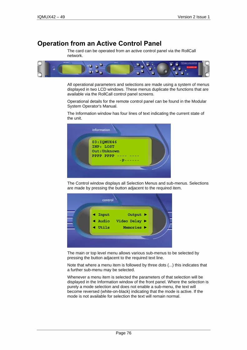
IQMUX42 – 49 Version 2 Issue 1
Page 76
Operation from an Active Control Panel The card can be operated from an active control panel via the RollCall network.
All operational parameters and selections are made using a system of menus displayed in two LCD windows. These menus duplicate the functions that are available via the RollCall control panel screens.
Operational details for the remote control panel can be found in the Modular System Operator's Manual.
The Information window has four lines of text indicating the current state of the unit.
The Control window displays all Selection Menus and sub-menus. Selections are made by pressing the button adjacent to the required item.
The main or top level menu allows various sub-menus to be selected by pressing the button adjacent to the required text line.
Note that where a menu item is followed by three dots (...) this indicates that a further sub-menu may be selected.
Whenever a menu item is selected the parameters of that selection will be displayed in the Information window of the front panel. Where the selection is purely a mode selection and does not enable a sub-menu, the text will become reversed (white-on-black) indicating that the mode is active. If the mode is not available for selection the text will remain normal.
03:IQMUX46 INP: LOST Out:Unknown PPPP PPPP ---- ---- -P------
◀ Input Output ▶◀ Audio Video Delay ▶◀ Utils Memories ▶
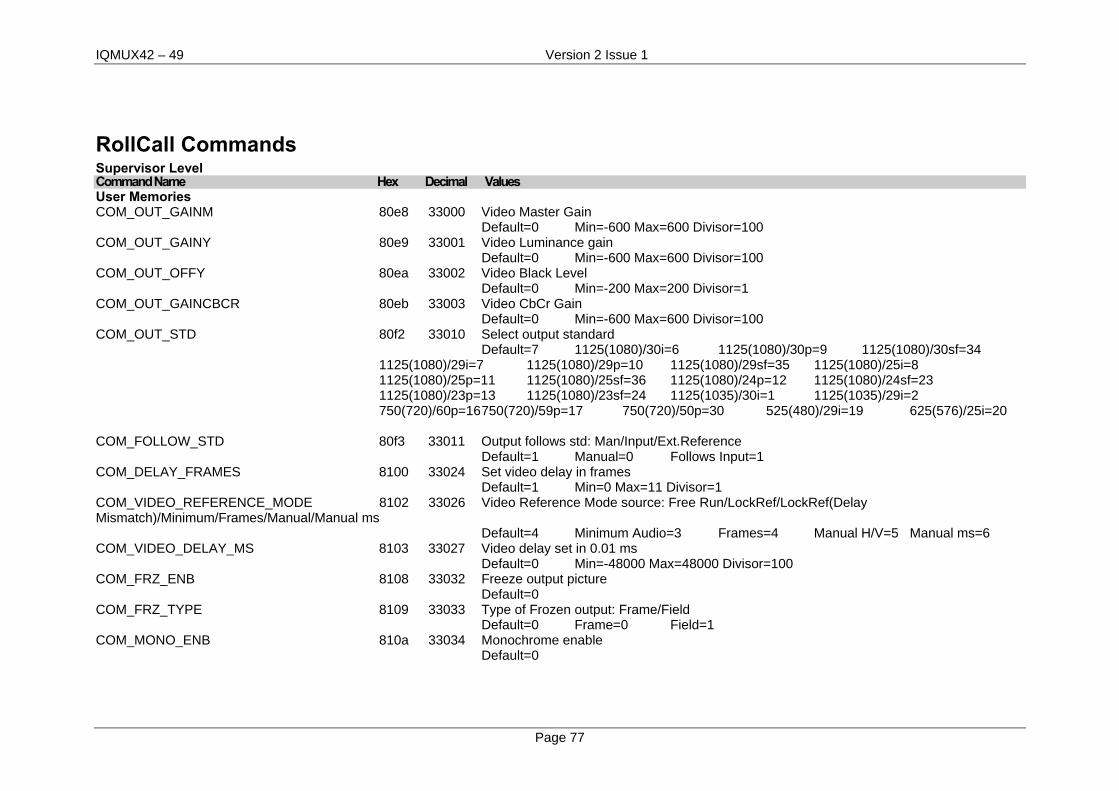
IQMUX42 – 49 Version 2 Issue 1
Page 77
RollCall Commands Supervisor Level Command Name Hex Decimal Values User Memories COM_OUT_GAINM 80e8 33000 Video Master Gain Default=0 Min=-600 Max=600 Divisor=100 COM_OUT_GAINY 80e9 33001 Video Luminance gain Default=0 Min=-600 Max=600 Divisor=100 COM_OUT_OFFY 80ea 33002 Video Black Level Default=0 Min=-200 Max=200 Divisor=1 COM_OUT_GAINCBCR 80eb 33003 Video CbCr Gain Default=0 Min=-600 Max=600 Divisor=100 COM_OUT_STD 80f2 33010 Select output standard Default=7 1125(1080)/30i=6 1125(1080)/30p=9 1125(1080)/30sf=34 1125(1080)/29i=7 1125(1080)/29p=10 1125(1080)/29sf=35 1125(1080)/25i=8 1125(1080)/25p=11 1125(1080)/25sf=36 1125(1080)/24p=12 1125(1080)/24sf=23 1125(1080)/23p=13 1125(1080)/23sf=24 1125(1035)/30i=1 1125(1035)/29i=2 750(720)/60p=16 750(720)/59p=17 750(720)/50p=30 525(480)/29i=19 625(576)/25i=20 COM_FOLLOW_STD 80f3 33011 Output follows std: Man/Input/Ext.Reference Default=1 Manual=0 Follows Input=1 COM_DELAY_FRAMES 8100 33024 Set video delay in frames Default=1 Min=0 Max=11 Divisor=1 COM_VIDEO_REFERENCE_MODE 8102 33026 Video Reference Mode source: Free Run/LockRef/LockRef(Delay Mismatch)/Minimum/Frames/Manual/Manual ms Default=4 Minimum Audio=3 Frames=4 Manual H/V=5 Manual ms=6 COM_VIDEO_DELAY_MS 8103 33027 Video delay set in 0.01 ms Default=0 Min=-48000 Max=48000 Divisor=100 COM_FRZ_ENB 8108 33032 Freeze output picture Default=0 COM_FRZ_TYPE 8109 33033 Type of Frozen output: Frame/Field Default=0 Frame=0 Field=1 COM_MONO_ENB 810a 33034 Monochrome enable Default=0
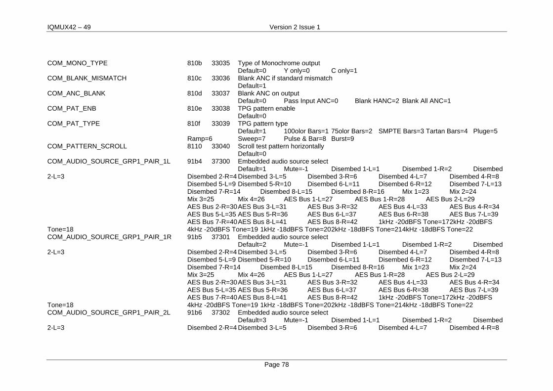
IQMUX42 – 49 Version 2 Issue 1
Page 78
COM_MONO_TYPE 810b 33035 Type of Monochrome output Default=0 Y only=0 C only=1 COM_BLANK_MISMATCH 810c 33036 Blank ANC if standard mismatch Default=1 COM_ANC_BLANK 810d 33037 Blank ANC on output Default=0 Pass Input ANC=0 Blank HANC=2 Blank All ANC=1 COM_PAT_ENB 810e 33038 TPG pattern enable Default=0 COM_PAT_TYPE 810f 33039 TPG pattern type Default=1 100olor Bars=1 75olor Bars=2 SMPTE Bars=3 Tartan Bars=4 Pluge=5 Ramp=6 Sweep=7 Pulse & Bar=8 Burst=9 COM_PATTERN_SCROLL 8110 33040 Scroll test pattern horizontally Default=0 COM_AUDIO_SOURCE_GRP1_PAIR_1L 91b4 37300 Embedded audio source select Default=1 Mute=-1 Disembed 1-L=1 Disembed 1-R=2 Disembed 2-L=3 Disembed 2-R=4 Disembed 3-L=5 Disembed 3-R=6 Disembed 4-L=7 Disembed 4-R=8 Disembed 5-L=9 Disembed 5-R=10 Disembed 6-L=11 Disembed 6-R=12 Disembed 7-L=13 Disembed 7-R=14 Disembed 8-L=15 Disembed 8-R=16 Mix 1=23 Mix 2=24 Mix 3=25 Mix 4=26 AES Bus 1-L=27 AES Bus 1-R=28 AES Bus 2-L=29 AES Bus 2-R=30 AES Bus 3-L=31 AES Bus 3-R=32 AES Bus 4-L=33 AES Bus 4-R=34 AES Bus 5-L=35 AES Bus 5-R=36 AES Bus 6-L=37 AES Bus 6-R=38 AES Bus 7-L=39 AES Bus 7-R=40 AES Bus 8-L=41 AES Bus 8-R=42 1kHz -20dBFS Tone=17 2kHz -20dBFS Tone=18 4kHz -20dBFS Tone=19 1kHz -18dBFS Tone=20 2kHz -18dBFS Tone=21 4kHz -18dBFS Tone=22 COM_AUDIO_SOURCE_GRP1_PAIR_1R 91b5 37301 Embedded audio source select Default=2 Mute=-1 Disembed 1-L=1 Disembed 1-R=2 Disembed 2-L=3 Disembed 2-R=4 Disembed 3-L=5 Disembed 3-R=6 Disembed 4-L=7 Disembed 4-R=8 Disembed 5-L=9 Disembed 5-R=10 Disembed 6-L=11 Disembed 6-R=12 Disembed 7-L=13 Disembed 7-R=14 Disembed 8-L=15 Disembed 8-R=16 Mix 1=23 Mix 2=24 Mix 3=25 Mix 4=26 AES Bus 1-L=27 AES Bus 1-R=28 AES Bus 2-L=29 AES Bus 2-R=30 AES Bus 3-L=31 AES Bus 3-R=32 AES Bus 4-L=33 AES Bus 4-R=34 AES Bus 5-L=35 AES Bus 5-R=36 AES Bus 6-L=37 AES Bus 6-R=38 AES Bus 7-L=39 AES Bus 7-R=40 AES Bus 8-L=41 AES Bus 8-R=42 1kHz -20dBFS Tone=17 2kHz -20dBFS Tone=18 4kHz -20dBFS Tone=19 1kHz -18dBFS Tone=20 2kHz -18dBFS Tone=21 4kHz -18dBFS Tone=22 COM_AUDIO_SOURCE_GRP1_PAIR_2L 91b6 37302 Embedded audio source select Default=3 Mute=-1 Disembed 1-L=1 Disembed 1-R=2 Disembed 2-L=3 Disembed 2-R=4 Disembed 3-L=5 Disembed 3-R=6 Disembed 4-L=7 Disembed 4-R=8
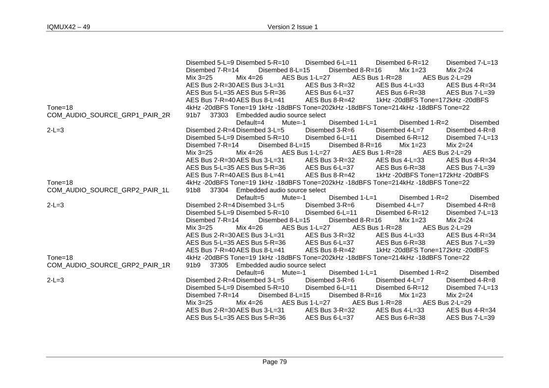
IQMUX42 – 49 Version 2 Issue 1
Page 79
Disembed 5-L=9 Disembed 5-R=10 Disembed 6-L=11 Disembed 6-R=12 Disembed 7-L=13 Disembed 7-R=14 Disembed 8-L=15 Disembed 8-R=16 Mix 1=23 Mix 2=24 Mix 3=25 Mix 4=26 AES Bus 1-L=27 AES Bus 1-R=28 AES Bus 2-L=29 AES Bus 2-R=30 AES Bus 3-L=31 AES Bus 3-R=32 AES Bus 4-L=33 AES Bus 4-R=34 AES Bus 5-L=35 AES Bus 5-R=36 AES Bus 6-L=37 AES Bus 6-R=38 AES Bus 7-L=39 AES Bus 7-R=40 AES Bus 8-L=41 AES Bus 8-R=42 1kHz -20dBFS Tone=17 2kHz -20dBFS Tone=18 4kHz -20dBFS Tone=19 1kHz -18dBFS Tone=20 2kHz -18dBFS Tone=21 4kHz -18dBFS Tone=22 COM_AUDIO_SOURCE_GRP1_PAIR_2R 91b7 37303 Embedded audio source select Default=4 Mute=-1 Disembed 1-L=1 Disembed 1-R=2 Disembed 2-L=3 Disembed 2-R=4 Disembed 3-L=5 Disembed 3-R=6 Disembed 4-L=7 Disembed 4-R=8 Disembed 5-L=9 Disembed 5-R=10 Disembed 6-L=11 Disembed 6-R=12 Disembed 7-L=13 Disembed 7-R=14 Disembed 8-L=15 Disembed 8-R=16 Mix 1=23 Mix 2=24 Mix 3=25 Mix 4=26 AES Bus 1-L=27 AES Bus 1-R=28 AES Bus 2-L=29 AES Bus 2-R=30 AES Bus 3-L=31 AES Bus 3-R=32 AES Bus 4-L=33 AES Bus 4-R=34 AES Bus 5-L=35 AES Bus 5-R=36 AES Bus 6-L=37 AES Bus 6-R=38 AES Bus 7-L=39 AES Bus 7-R=40 AES Bus 8-L=41 AES Bus 8-R=42 1kHz -20dBFS Tone=17 2kHz -20dBFS Tone=18 4kHz -20dBFS Tone=19 1kHz -18dBFS Tone=20 2kHz -18dBFS Tone=21 4kHz -18dBFS Tone=22 COM_AUDIO_SOURCE_GRP2_PAIR_1L 91b8 37304 Embedded audio source select Default=5 Mute=-1 Disembed 1-L=1 Disembed 1-R=2 Disembed 2-L=3 Disembed 2-R=4 Disembed 3-L=5 Disembed 3-R=6 Disembed 4-L=7 Disembed 4-R=8 Disembed 5-L=9 Disembed 5-R=10 Disembed 6-L=11 Disembed 6-R=12 Disembed 7-L=13 Disembed 7-R=14 Disembed 8-L=15 Disembed 8-R=16 Mix 1=23 Mix 2=24 Mix 3=25 Mix 4=26 AES Bus 1-L=27 AES Bus 1-R=28 AES Bus 2-L=29 AES Bus 2-R=30 AES Bus 3-L=31 AES Bus 3-R=32 AES Bus 4-L=33 AES Bus 4-R=34 AES Bus 5-L=35 AES Bus 5-R=36 AES Bus 6-L=37 AES Bus 6-R=38 AES Bus 7-L=39 AES Bus 7-R=40 AES Bus 8-L=41 AES Bus 8-R=42 1kHz -20dBFS Tone=17 2kHz -20dBFS Tone=18 4kHz -20dBFS Tone=19 1kHz -18dBFS Tone=20 2kHz -18dBFS Tone=21 4kHz -18dBFS Tone=22 COM_AUDIO_SOURCE_GRP2_PAIR_1R 91b9 37305 Embedded audio source select Default=6 Mute=-1 Disembed 1-L=1 Disembed 1-R=2 Disembed 2-L=3 Disembed 2-R=4 Disembed 3-L=5 Disembed 3-R=6 Disembed 4-L=7 Disembed 4-R=8 Disembed 5-L=9 Disembed 5-R=10 Disembed 6-L=11 Disembed 6-R=12 Disembed 7-L=13 Disembed 7-R=14 Disembed 8-L=15 Disembed 8-R=16 Mix 1=23 Mix 2=24 Mix 3=25 Mix 4=26 AES Bus 1-L=27 AES Bus 1-R=28 AES Bus 2-L=29 AES Bus 2-R=30 AES Bus 3-L=31 AES Bus 3-R=32 AES Bus 4-L=33 AES Bus 4-R=34 AES Bus 5-L=35 AES Bus 5-R=36 AES Bus 6-L=37 AES Bus 6-R=38 AES Bus 7-L=39
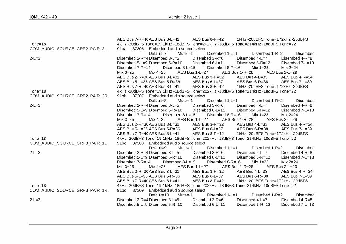
IQMUX42 – 49 Version 2 Issue 1
Page 80
AES Bus 7-R=40 AES Bus 8-L=41 AES Bus 8-R=42 1kHz -20dBFS Tone=17 2kHz -20dBFS Tone=18 4kHz -20dBFS Tone=19 1kHz -18dBFS Tone=20 2kHz -18dBFS Tone=21 4kHz -18dBFS Tone=22 COM_AUDIO_SOURCE_GRP2_PAIR_2L 91ba 37306 Embedded audio source select Default=7 Mute=-1 Disembed 1-L=1 Disembed 1-R=2 Disembed 2-L=3 Disembed 2-R=4 Disembed 3-L=5 Disembed 3-R=6 Disembed 4-L=7 Disembed 4-R=8 Disembed 5-L=9 Disembed 5-R=10 Disembed 6-L=11 Disembed 6-R=12 Disembed 7-L=13 Disembed 7-R=14 Disembed 8-L=15 Disembed 8-R=16 Mix 1=23 Mix 2=24 Mix 3=25 Mix 4=26 AES Bus 1-L=27 AES Bus 1-R=28 AES Bus 2-L=29 AES Bus 2-R=30 AES Bus 3-L=31 AES Bus 3-R=32 AES Bus 4-L=33 AES Bus 4-R=34 AES Bus 5-L=35 AES Bus 5-R=36 AES Bus 6-L=37 AES Bus 6-R=38 AES Bus 7-L=39 AES Bus 7-R=40 AES Bus 8-L=41 AES Bus 8-R=42 1kHz -20dBFS Tone=17 2kHz -20dBFS Tone=18 4kHz -20dBFS Tone=19 1kHz -18dBFS Tone=20 2kHz -18dBFS Tone=21 4kHz -18dBFS Tone=22 COM_AUDIO_SOURCE_GRP2_PAIR_2R 91bb 37307 Embedded audio source select Default=8 Mute=-1 Disembed 1-L=1 Disembed 1-R=2 Disembed 2-L=3 Disembed 2-R=4 Disembed 3-L=5 Disembed 3-R=6 Disembed 4-L=7 Disembed 4-R=8 Disembed 5-L=9 Disembed 5-R=10 Disembed 6-L=11 Disembed 6-R=12 Disembed 7-L=13 Disembed 7-R=14 Disembed 8-L=15 Disembed 8-R=16 Mix 1=23 Mix 2=24 Mix 3=25 Mix 4=26 AES Bus 1-L=27 AES Bus 1-R=28 AES Bus 2-L=29 AES Bus 2-R=30 AES Bus 3-L=31 AES Bus 3-R=32 AES Bus 4-L=33 AES Bus 4-R=34 AES Bus 5-L=35 AES Bus 5-R=36 AES Bus 6-L=37 AES Bus 6-R=38 AES Bus 7-L=39 AES Bus 7-R=40 AES Bus 8-L=41 AES Bus 8-R=42 1kHz -20dBFS Tone=17 2kHz -20dBFS Tone=18 4kHz -20dBFS Tone=19 1kHz -18dBFS Tone=20 2kHz -18dBFS Tone=21 4kHz -18dBFS Tone=22 COM_AUDIO_SOURCE_GRP3_PAIR_1L 91bc 37308 Embedded audio source select Default=9 Mute=-1 Disembed 1-L=1 Disembed 1-R=2 Disembed 2-L=3 Disembed 2-R=4 Disembed 3-L=5 Disembed 3-R=6 Disembed 4-L=7 Disembed 4-R=8 Disembed 5-L=9 Disembed 5-R=10 Disembed 6-L=11 Disembed 6-R=12 Disembed 7-L=13 Disembed 7-R=14 Disembed 8-L=15 Disembed 8-R=16 Mix 1=23 Mix 2=24 Mix 3=25 Mix 4=26 AES Bus 1-L=27 AES Bus 1-R=28 AES Bus 2-L=29 AES Bus 2-R=30 AES Bus 3-L=31 AES Bus 3-R=32 AES Bus 4-L=33 AES Bus 4-R=34 AES Bus 5-L=35 AES Bus 5-R=36 AES Bus 6-L=37 AES Bus 6-R=38 AES Bus 7-L=39 AES Bus 7-R=40 AES Bus 8-L=41 AES Bus 8-R=42 1kHz -20dBFS Tone=17 2kHz -20dBFS Tone=18 4kHz -20dBFS Tone=19 1kHz -18dBFS Tone=20 2kHz -18dBFS Tone=21 4kHz -18dBFS Tone=22 COM_AUDIO_SOURCE_GRP3_PAIR_1R 91bd 37309 Embedded audio source select Default=10 Mute=-1 Disembed 1-L=1 Disembed 1-R=2 Disembed 2-L=3 Disembed 2-R=4 Disembed 3-L=5 Disembed 3-R=6 Disembed 4-L=7 Disembed 4-R=8 Disembed 5-L=9 Disembed 5-R=10 Disembed 6-L=11 Disembed 6-R=12 Disembed 7-L=13
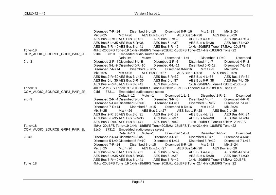
IQMUX42 – 49 Version 2 Issue 1
Page 81
Disembed 7-R=14 Disembed 8-L=15 Disembed 8-R=16 Mix 1=23 Mix 2=24 Mix 3=25 Mix 4=26 AES Bus 1-L=27 AES Bus 1-R=28 AES Bus 2-L=29 AES Bus 2-R=30 AES Bus 3-L=31 AES Bus 3-R=32 AES Bus 4-L=33 AES Bus 4-R=34 AES Bus 5-L=35 AES Bus 5-R=36 AES Bus 6-L=37 AES Bus 6-R=38 AES Bus 7-L=39 AES Bus 7-R=40 AES Bus 8-L=41 AES Bus 8-R=42 1kHz -20dBFS Tone=17 2kHz -20dBFS Tone=18 4kHz -20dBFS Tone=19 1kHz -18dBFS Tone=20 2kHz -18dBFS Tone=21 4kHz -18dBFS Tone=22 COM_AUDIO_SOURCE_GRP3_PAIR_2L 91be 37310 Embedded audio source select Default=11 Mute=-1 Disembed 1-L=1 Disembed 1-R=2 Disembed 2-L=3 Disembed 2-R=4 Disembed 3-L=5 Disembed 3-R=6 Disembed 4-L=7 Disembed 4-R=8 Disembed 5-L=9 Disembed 5-R=10 Disembed 6-L=11 Disembed 6-R=12 Disembed 7-L=13 Disembed 7-R=14 Disembed 8-L=15 Disembed 8-R=16 Mix 1=23 Mix 2=24 Mix 3=25 Mix 4=26 AES Bus 1-L=27 AES Bus 1-R=28 AES Bus 2-L=29 AES Bus 2-R=30 AES Bus 3-L=31 AES Bus 3-R=32 AES Bus 4-L=33 AES Bus 4-R=34 AES Bus 5-L=35 AES Bus 5-R=36 AES Bus 6-L=37 AES Bus 6-R=38 AES Bus 7-L=39 AES Bus 7-R=40 AES Bus 8-L=41 AES Bus 8-R=42 1kHz -20dBFS Tone=17 2kHz -20dBFS Tone=18 4kHz -20dBFS Tone=19 1kHz -18dBFS Tone=20 2kHz -18dBFS Tone=21 4kHz -18dBFS Tone=22 COM_AUDIO_SOURCE_GRP3_PAIR_2R 91bf 37311 Embedded audio source select Default=12 Mute=-1 Disembed 1-L=1 Disembed 1-R=2 Disembed 2-L=3 Disembed 2-R=4 Disembed 3-L=5 Disembed 3-R=6 Disembed 4-L=7 Disembed 4-R=8 Disembed 5-L=9 Disembed 5-R=10 Disembed 6-L=11 Disembed 6-R=12 Disembed 7-L=13 Disembed 7-R=14 Disembed 8-L=15 Disembed 8-R=16 Mix 1=23 Mix 2=24 Mix 3=25 Mix 4=26 AES Bus 1-L=27 AES Bus 1-R=28 AES Bus 2-L=29 AES Bus 2-R=30 AES Bus 3-L=31 AES Bus 3-R=32 AES Bus 4-L=33 AES Bus 4-R=34 AES Bus 5-L=35 AES Bus 5-R=36 AES Bus 6-L=37 AES Bus 6-R=38 AES Bus 7-L=39 AES Bus 7-R=40 AES Bus 8-L=41 AES Bus 8-R=42 1kHz -20dBFS Tone=17 2kHz -20dBFS Tone=18 4kHz -20dBFS Tone=19 1kHz -18dBFS Tone=20 2kHz -18dBFS Tone=21 4kHz -18dBFS Tone=22 COM_AUDIO_SOURCE_GRP4_PAIR_1L 91c0 37312 Embedded audio source select Default=13 Mute=-1 Disembed 1-L=1 Disembed 1-R=2 Disembed 2-L=3 Disembed 2-R=4 Disembed 3-L=5 Disembed 3-R=6 Disembed 4-L=7 Disembed 4-R=8 Disembed 5-L=9 Disembed 5-R=10 Disembed 6-L=11 Disembed 6-R=12 Disembed 7-L=13 Disembed 7-R=14 Disembed 8-L=15 Disembed 8-R=16 Mix 1=23 Mix 2=24 Mix 3=25 Mix 4=26 AES Bus 1-L=27 AES Bus 1-R=28 AES Bus 2-L=29 AES Bus 2-R=30 AES Bus 3-L=31 AES Bus 3-R=32 AES Bus 4-L=33 AES Bus 4-R=34 AES Bus 5-L=35 AES Bus 5-R=36 AES Bus 6-L=37 AES Bus 6-R=38 AES Bus 7-L=39 AES Bus 7-R=40 AES Bus 8-L=41 AES Bus 8-R=42 1kHz -20dBFS Tone=17 2kHz -20dBFS Tone=18 4kHz -20dBFS Tone=19 1kHz -18dBFS Tone=20 2kHz -18dBFS Tone=21 4kHz -18dBFS Tone=22
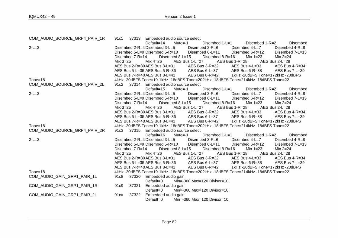
IQMUX42 – 49 Version 2 Issue 1
Page 82
COM_AUDIO_SOURCE_GRP4_PAIR_1R 91c1 37313 Embedded audio source select Default=14 Mute=-1 Disembed 1-L=1 Disembed 1-R=2 Disembed 2-L=3 Disembed 2-R=4 Disembed 3-L=5 Disembed 3-R=6 Disembed 4-L=7 Disembed 4-R=8 Disembed 5-L=9 Disembed 5-R=10 Disembed 6-L=11 Disembed 6-R=12 Disembed 7-L=13 Disembed 7-R=14 Disembed 8-L=15 Disembed 8-R=16 Mix 1=23 Mix 2=24 Mix 3=25 Mix 4=26 AES Bus 1-L=27 AES Bus 1-R=28 AES Bus 2-L=29 AES Bus 2-R=30 AES Bus 3-L=31 AES Bus 3-R=32 AES Bus 4-L=33 AES Bus 4-R=34 AES Bus 5-L=35 AES Bus 5-R=36 AES Bus 6-L=37 AES Bus 6-R=38 AES Bus 7-L=39 AES Bus 7-R=40 AES Bus 8-L=41 AES Bus 8-R=42 1kHz -20dBFS Tone=17 2kHz -20dBFS Tone=18 4kHz -20dBFS Tone=19 1kHz -18dBFS Tone=20 2kHz -18dBFS Tone=21 4kHz -18dBFS Tone=22 COM_AUDIO_SOURCE_GRP4_PAIR_2L 91c2 37314 Embedded audio source select Default=15 Mute=-1 Disembed 1-L=1 Disembed 1-R=2 Disembed 2-L=3 Disembed 2-R=4 Disembed 3-L=5 Disembed 3-R=6 Disembed 4-L=7 Disembed 4-R=8 Disembed 5-L=9 Disembed 5-R=10 Disembed 6-L=11 Disembed 6-R=12 Disembed 7-L=13 Disembed 7-R=14 Disembed 8-L=15 Disembed 8-R=16 Mix 1=23 Mix 2=24 Mix 3=25 Mix 4=26 AES Bus 1-L=27 AES Bus 1-R=28 AES Bus 2-L=29 AES Bus 2-R=30 AES Bus 3-L=31 AES Bus 3-R=32 AES Bus 4-L=33 AES Bus 4-R=34 AES Bus 5-L=35 AES Bus 5-R=36 AES Bus 6-L=37 AES Bus 6-R=38 AES Bus 7-L=39 AES Bus 7-R=40 AES Bus 8-L=41 AES Bus 8-R=42 1kHz -20dBFS Tone=17 2kHz -20dBFS Tone=18 4kHz -20dBFS Tone=19 1kHz -18dBFS Tone=20 2kHz -18dBFS Tone=21 4kHz -18dBFS Tone=22 COM_AUDIO_SOURCE_GRP4_PAIR_2R 91c3 37315 Embedded audio source select Default=16 Mute=-1 Disembed 1-L=1 Disembed 1-R=2 Disembed 2-L=3 Disembed 2-R=4 Disembed 3-L=5 Disembed 3-R=6 Disembed 4-L=7 Disembed 4-R=8 Disembed 5-L=9 Disembed 5-R=10 Disembed 6-L=11 Disembed 6-R=12 Disembed 7-L=13 Disembed 7-R=14 Disembed 8-L=15 Disembed 8-R=16 Mix 1=23 Mix 2=24 Mix 3=25 Mix 4=26 AES Bus 1-L=27 AES Bus 1-R=28 AES Bus 2-L=29 AES Bus 2-R=30 AES Bus 3-L=31 AES Bus 3-R=32 AES Bus 4-L=33 AES Bus 4-R=34 AES Bus 5-L=35 AES Bus 5-R=36 AES Bus 6-L=37 AES Bus 6-R=38 AES Bus 7-L=39 AES Bus 7-R=40 AES Bus 8-L=41 AES Bus 8-R=42 1kHz -20dBFS Tone=17 2kHz -20dBFS Tone=18 4kHz -20dBFS Tone=19 1kHz -18dBFS Tone=20 2kHz -18dBFS Tone=21 4kHz -18dBFS Tone=22 COM_AUDIO_GAIN_GRP1_PAIR_1L 91c8 37320 Embedded audio gain Default=0 Min=-360 Max=120 Divisor=10 COM_AUDIO_GAIN_GRP1_PAIR_1R 91c9 37321 Embedded audio gain Default=0 Min=-360 Max=120 Divisor=10 COM_AUDIO_GAIN_GRP1_PAIR_2L 91ca 37322 Embedded audio gain Default=0 Min=-360 Max=120 Divisor=10
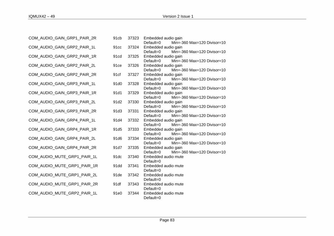
IQMUX42 – 49 Version 2 Issue 1
Page 83
COM_AUDIO_GAIN_GRP1_PAIR_2R 91cb 37323 Embedded audio gain Default=0 Min=-360 Max=120 Divisor=10 COM_AUDIO_GAIN_GRP2_PAIR_1L 91cc 37324 Embedded audio gain Default=0 Min=-360 Max=120 Divisor=10 COM_AUDIO_GAIN_GRP2_PAIR_1R 91cd 37325 Embedded audio gain Default=0 Min=-360 Max=120 Divisor=10 COM_AUDIO_GAIN_GRP2_PAIR_2L 91ce 37326 Embedded audio gain Default=0 Min=-360 Max=120 Divisor=10 COM_AUDIO_GAIN_GRP2_PAIR_2R 91cf 37327 Embedded audio gain Default=0 Min=-360 Max=120 Divisor=10 COM_AUDIO_GAIN_GRP3_PAIR_1L 91d0 37328 Embedded audio gain Default=0 Min=-360 Max=120 Divisor=10 COM_AUDIO_GAIN_GRP3_PAIR_1R 91d1 37329 Embedded audio gain Default=0 Min=-360 Max=120 Divisor=10 COM_AUDIO_GAIN_GRP3_PAIR_2L 91d2 37330 Embedded audio gain Default=0 Min=-360 Max=120 Divisor=10 COM_AUDIO_GAIN_GRP3_PAIR_2R 91d3 37331 Embedded audio gain Default=0 Min=-360 Max=120 Divisor=10 COM_AUDIO_GAIN_GRP4_PAIR_1L 91d4 37332 Embedded audio gain Default=0 Min=-360 Max=120 Divisor=10 COM_AUDIO_GAIN_GRP4_PAIR_1R 91d5 37333 Embedded audio gain Default=0 Min=-360 Max=120 Divisor=10 COM_AUDIO_GAIN_GRP4_PAIR_2L 91d6 37334 Embedded audio gain Default=0 Min=-360 Max=120 Divisor=10 COM_AUDIO_GAIN_GRP4_PAIR_2R 91d7 37335 Embedded audio gain Default=0 Min=-360 Max=120 Divisor=10 COM_AUDIO_MUTE_GRP1_PAIR_1L 91dc 37340 Embedded audio mute Default=0 COM_AUDIO_MUTE_GRP1_PAIR_1R 91dd 37341 Embedded audio mute Default=0 COM_AUDIO_MUTE_GRP1_PAIR_2L 91de 37342 Embedded audio mute Default=0 COM_AUDIO_MUTE_GRP1_PAIR_2R 91df 37343 Embedded audio mute Default=0 COM_AUDIO_MUTE_GRP2_PAIR_1L 91e0 37344 Embedded audio mute Default=0
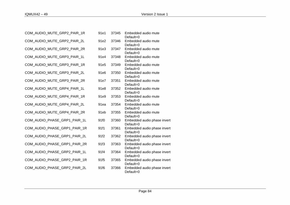
IQMUX42 – 49 Version 2 Issue 1
Page 84
COM_AUDIO_MUTE_GRP2_PAIR_1R 91e1 37345 Embedded audio mute Default=0 COM_AUDIO_MUTE_GRP2_PAIR_2L 91e2 37346 Embedded audio mute Default=0 COM_AUDIO_MUTE_GRP2_PAIR_2R 91e3 37347 Embedded audio mute Default=0 COM_AUDIO_MUTE_GRP3_PAIR_1L 91e4 37348 Embedded audio mute Default=0 COM_AUDIO_MUTE_GRP3_PAIR_1R 91e5 37349 Embedded audio mute Default=0 COM_AUDIO_MUTE_GRP3_PAIR_2L 91e6 37350 Embedded audio mute Default=0 COM_AUDIO_MUTE_GRP3_PAIR_2R 91e7 37351 Embedded audio mute Default=0 COM_AUDIO_MUTE_GRP4_PAIR_1L 91e8 37352 Embedded audio mute Default=0 COM_AUDIO_MUTE_GRP4_PAIR_1R 91e9 37353 Embedded audio mute Default=0 COM_AUDIO_MUTE_GRP4_PAIR_2L 91ea 37354 Embedded audio mute Default=0 COM_AUDIO_MUTE_GRP4_PAIR_2R 91eb 37355 Embedded audio mute Default=0 COM_AUDIO_PHASE_GRP1_PAIR_1L 91f0 37360 Embedded audio phase invert Default=0 COM_AUDIO_PHASE_GRP1_PAIR_1R 91f1 37361 Embedded audio phase invert Default=0 COM_AUDIO_PHASE_GRP1_PAIR_2L 91f2 37362 Embedded audio phase invert Default=0 COM_AUDIO_PHASE_GRP1_PAIR_2R 91f3 37363 Embedded audio phase invert Default=0 COM_AUDIO_PHASE_GRP2_PAIR_1L 91f4 37364 Embedded audio phase invert Default=0 COM_AUDIO_PHASE_GRP2_PAIR_1R 91f5 37365 Embedded audio phase invert Default=0 COM_AUDIO_PHASE_GRP2_PAIR_2L 91f6 37366 Embedded audio phase invert Default=0
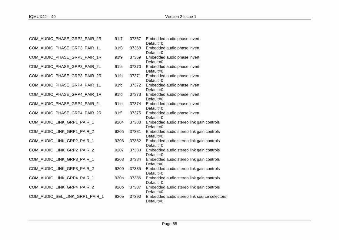
IQMUX42 – 49 Version 2 Issue 1
Page 85
COM_AUDIO_PHASE_GRP2_PAIR_2R 91f7 37367 Embedded audio phase invert Default=0 COM_AUDIO_PHASE_GRP3_PAIR_1L 91f8 37368 Embedded audio phase invert Default=0 COM_AUDIO_PHASE_GRP3_PAIR_1R 91f9 37369 Embedded audio phase invert Default=0 COM_AUDIO_PHASE_GRP3_PAIR_2L 91fa 37370 Embedded audio phase invert Default=0 COM_AUDIO_PHASE_GRP3_PAIR_2R 91fb 37371 Embedded audio phase invert Default=0 COM_AUDIO_PHASE_GRP4_PAIR_1L 91fc 37372 Embedded audio phase invert Default=0 COM_AUDIO_PHASE_GRP4_PAIR_1R 91fd 37373 Embedded audio phase invert Default=0 COM_AUDIO_PHASE_GRP4_PAIR_2L 91fe 37374 Embedded audio phase invert Default=0 COM_AUDIO_PHASE_GRP4_PAIR_2R 91ff 37375 Embedded audio phase invert Default=0 COM_AUDIO_LINK_GRP1_PAIR_1 9204 37380 Embedded audio stereo link gain controls Default=0 COM_AUDIO_LINK_GRP1_PAIR_2 9205 37381 Embedded audio stereo link gain controls Default=0 COM_AUDIO_LINK_GRP2_PAIR_1 9206 37382 Embedded audio stereo link gain controls Default=0 COM_AUDIO_LINK_GRP2_PAIR_2 9207 37383 Embedded audio stereo link gain controls Default=0 COM_AUDIO_LINK_GRP3_PAIR_1 9208 37384 Embedded audio stereo link gain controls Default=0 COM_AUDIO_LINK_GRP3_PAIR_2 9209 37385 Embedded audio stereo link gain controls Default=0 COM_AUDIO_LINK_GRP4_PAIR_1 920a 37386 Embedded audio stereo link gain controls Default=0 COM_AUDIO_LINK_GRP4_PAIR_2 920b 37387 Embedded audio stereo link gain controls Default=0 COM_AUDIO_SEL_LINK_GRP1_PAIR_1 920e 37390 Embedded audio stereo link source selectors Default=0
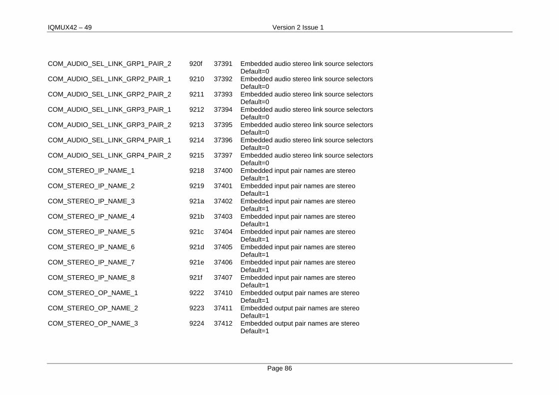
IQMUX42 – 49 Version 2 Issue 1
Page 86
COM_AUDIO_SEL_LINK_GRP1_PAIR_2 920f 37391 Embedded audio stereo link source selectors Default=0 COM_AUDIO_SEL_LINK_GRP2_PAIR_1 9210 37392 Embedded audio stereo link source selectors Default=0 COM_AUDIO_SEL_LINK_GRP2_PAIR_2 9211 37393 Embedded audio stereo link source selectors Default=0 COM_AUDIO_SEL_LINK_GRP3_PAIR_1 9212 37394 Embedded audio stereo link source selectors Default=0 COM_AUDIO_SEL_LINK_GRP3_PAIR_2 9213 37395 Embedded audio stereo link source selectors Default=0 COM_AUDIO_SEL_LINK_GRP4_PAIR_1 9214 37396 Embedded audio stereo link source selectors Default=0 COM_AUDIO_SEL_LINK_GRP4_PAIR_2 9215 37397 Embedded audio stereo link source selectors Default=0 COM_STEREO_IP_NAME_1 9218 37400 Embedded input pair names are stereo Default=1 COM_STEREO_IP_NAME_2 9219 37401 Embedded input pair names are stereo Default=1 COM_STEREO_IP_NAME_3 921a 37402 Embedded input pair names are stereo Default=1 COM_STEREO_IP_NAME_4 921b 37403 Embedded input pair names are stereo Default=1 COM_STEREO_IP_NAME_5 921c 37404 Embedded input pair names are stereo Default=1 COM_STEREO_IP_NAME_6 921d 37405 Embedded input pair names are stereo Default=1 COM_STEREO_IP_NAME_7 921e 37406 Embedded input pair names are stereo Default=1 COM_STEREO_IP_NAME_8 921f 37407 Embedded input pair names are stereo Default=1 COM_STEREO_OP_NAME_1 9222 37410 Embedded output pair names are stereo Default=1 COM_STEREO_OP_NAME_2 9223 37411 Embedded output pair names are stereo Default=1 COM_STEREO_OP_NAME_3 9224 37412 Embedded output pair names are stereo Default=1
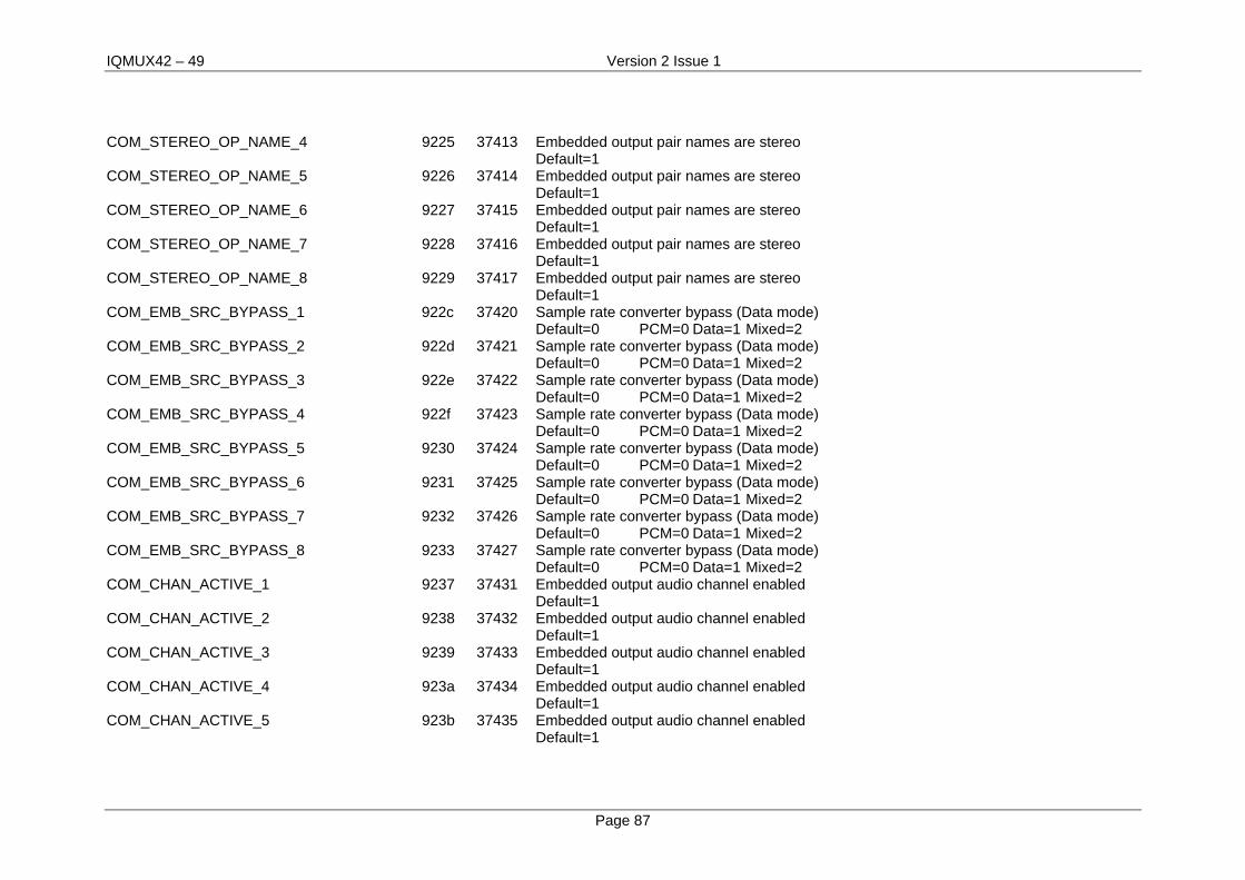
IQMUX42 – 49 Version 2 Issue 1
Page 87
COM_STEREO_OP_NAME_4 9225 37413 Embedded output pair names are stereo Default=1 COM_STEREO_OP_NAME_5 9226 37414 Embedded output pair names are stereo Default=1 COM_STEREO_OP_NAME_6 9227 37415 Embedded output pair names are stereo Default=1 COM_STEREO_OP_NAME_7 9228 37416 Embedded output pair names are stereo Default=1 COM_STEREO_OP_NAME_8 9229 37417 Embedded output pair names are stereo Default=1 COM_EMB_SRC_BYPASS_1 922c 37420 Sample rate converter bypass (Data mode) Default=0 PCM=0 Data=1 Mixed=2 COM_EMB_SRC_BYPASS_2 922d 37421 Sample rate converter bypass (Data mode) Default=0 PCM=0 Data=1 Mixed=2 COM_EMB_SRC_BYPASS_3 922e 37422 Sample rate converter bypass (Data mode) Default=0 PCM=0 Data=1 Mixed=2 COM_EMB_SRC_BYPASS_4 922f 37423 Sample rate converter bypass (Data mode) Default=0 PCM=0 Data=1 Mixed=2 COM_EMB_SRC_BYPASS_5 9230 37424 Sample rate converter bypass (Data mode) Default=0 PCM=0 Data=1 Mixed=2 COM_EMB_SRC_BYPASS_6 9231 37425 Sample rate converter bypass (Data mode) Default=0 PCM=0 Data=1 Mixed=2 COM_EMB_SRC_BYPASS_7 9232 37426 Sample rate converter bypass (Data mode) Default=0 PCM=0 Data=1 Mixed=2 COM_EMB_SRC_BYPASS_8 9233 37427 Sample rate converter bypass (Data mode) Default=0 PCM=0 Data=1 Mixed=2 COM_CHAN_ACTIVE_1 9237 37431 Embedded output audio channel enabled Default=1 COM_CHAN_ACTIVE_2 9238 37432 Embedded output audio channel enabled Default=1 COM_CHAN_ACTIVE_3 9239 37433 Embedded output audio channel enabled Default=1 COM_CHAN_ACTIVE_4 923a 37434 Embedded output audio channel enabled Default=1 COM_CHAN_ACTIVE_5 923b 37435 Embedded output audio channel enabled Default=1
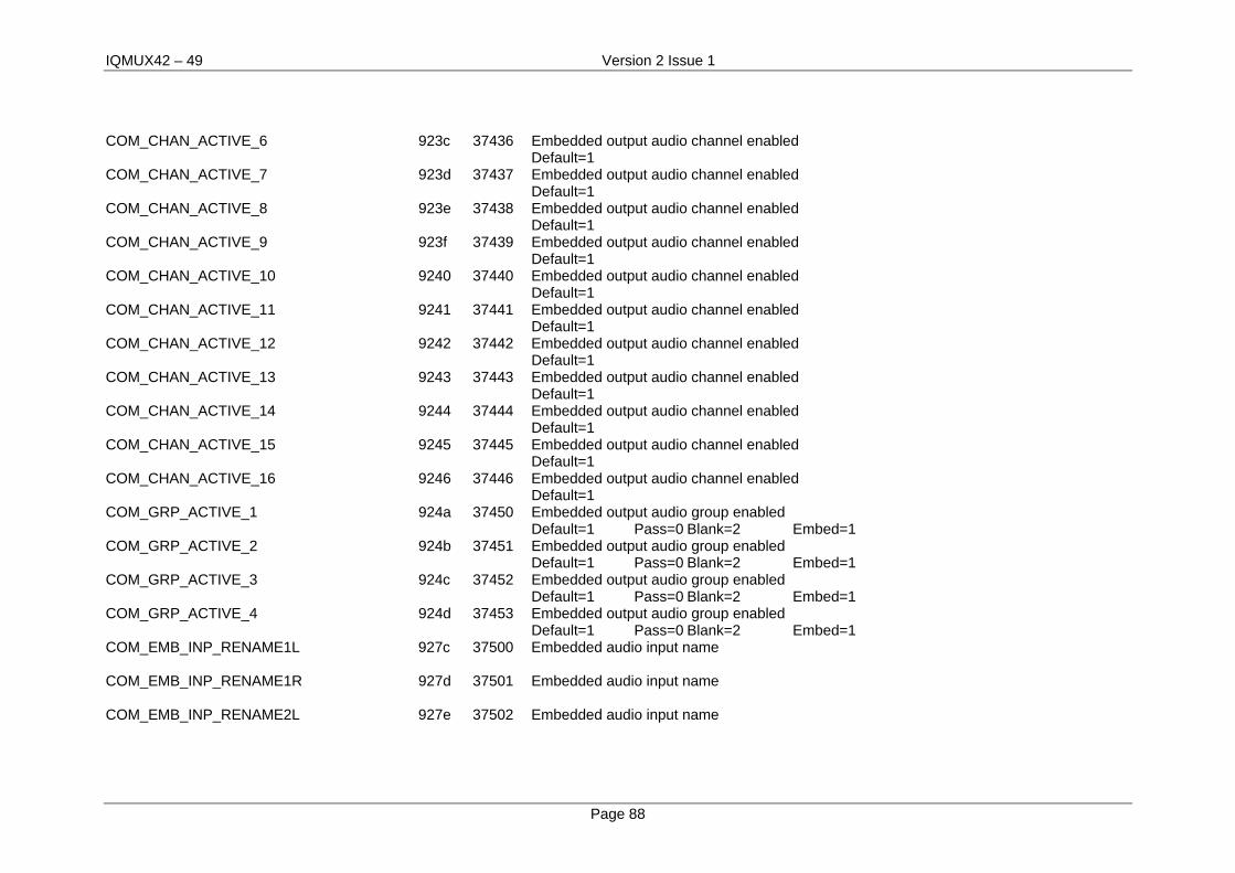
IQMUX42 – 49 Version 2 Issue 1
Page 88
COM_CHAN_ACTIVE_6 923c 37436 Embedded output audio channel enabled Default=1 COM_CHAN_ACTIVE_7 923d 37437 Embedded output audio channel enabled Default=1 COM_CHAN_ACTIVE_8 923e 37438 Embedded output audio channel enabled Default=1 COM_CHAN_ACTIVE_9 923f 37439 Embedded output audio channel enabled Default=1 COM_CHAN_ACTIVE_10 9240 37440 Embedded output audio channel enabled Default=1 COM_CHAN_ACTIVE_11 9241 37441 Embedded output audio channel enabled Default=1 COM_CHAN_ACTIVE_12 9242 37442 Embedded output audio channel enabled Default=1 COM_CHAN_ACTIVE_13 9243 37443 Embedded output audio channel enabled Default=1 COM_CHAN_ACTIVE_14 9244 37444 Embedded output audio channel enabled Default=1 COM_CHAN_ACTIVE_15 9245 37445 Embedded output audio channel enabled Default=1 COM_CHAN_ACTIVE_16 9246 37446 Embedded output audio channel enabled Default=1 COM_GRP_ACTIVE_1 924a 37450 Embedded output audio group enabled Default=1 Pass=0 Blank=2 Embed=1 COM_GRP_ACTIVE_2 924b 37451 Embedded output audio group enabled Default=1 Pass=0 Blank=2 Embed=1 COM_GRP_ACTIVE_3 924c 37452 Embedded output audio group enabled Default=1 Pass=0 Blank=2 Embed=1 COM_GRP_ACTIVE_4 924d 37453 Embedded output audio group enabled Default=1 Pass=0 Blank=2 Embed=1 COM_EMB_INP_RENAME1L 927c 37500 Embedded audio input name COM_EMB_INP_RENAME1R 927d 37501 Embedded audio input name COM_EMB_INP_RENAME2L 927e 37502 Embedded audio input name
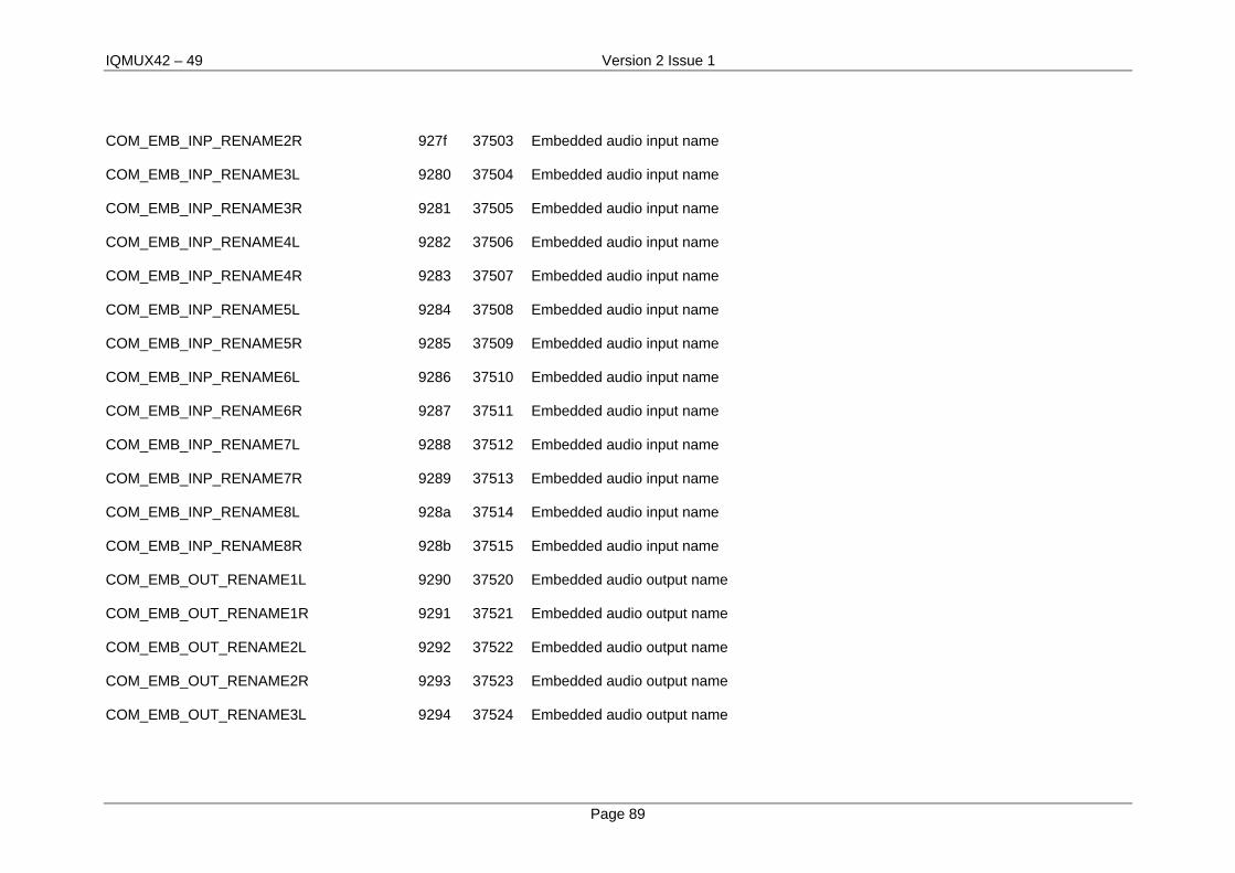
IQMUX42 – 49 Version 2 Issue 1
Page 89
COM_EMB_INP_RENAME2R 927f 37503 Embedded audio input name COM_EMB_INP_RENAME3L 9280 37504 Embedded audio input name COM_EMB_INP_RENAME3R 9281 37505 Embedded audio input name COM_EMB_INP_RENAME4L 9282 37506 Embedded audio input name COM_EMB_INP_RENAME4R 9283 37507 Embedded audio input name COM_EMB_INP_RENAME5L 9284 37508 Embedded audio input name COM_EMB_INP_RENAME5R 9285 37509 Embedded audio input name COM_EMB_INP_RENAME6L 9286 37510 Embedded audio input name COM_EMB_INP_RENAME6R 9287 37511 Embedded audio input name COM_EMB_INP_RENAME7L 9288 37512 Embedded audio input name COM_EMB_INP_RENAME7R 9289 37513 Embedded audio input name COM_EMB_INP_RENAME8L 928a 37514 Embedded audio input name COM_EMB_INP_RENAME8R 928b 37515 Embedded audio input name COM_EMB_OUT_RENAME1L 9290 37520 Embedded audio output name COM_EMB_OUT_RENAME1R 9291 37521 Embedded audio output name COM_EMB_OUT_RENAME2L 9292 37522 Embedded audio output name COM_EMB_OUT_RENAME2R 9293 37523 Embedded audio output name COM_EMB_OUT_RENAME3L 9294 37524 Embedded audio output name
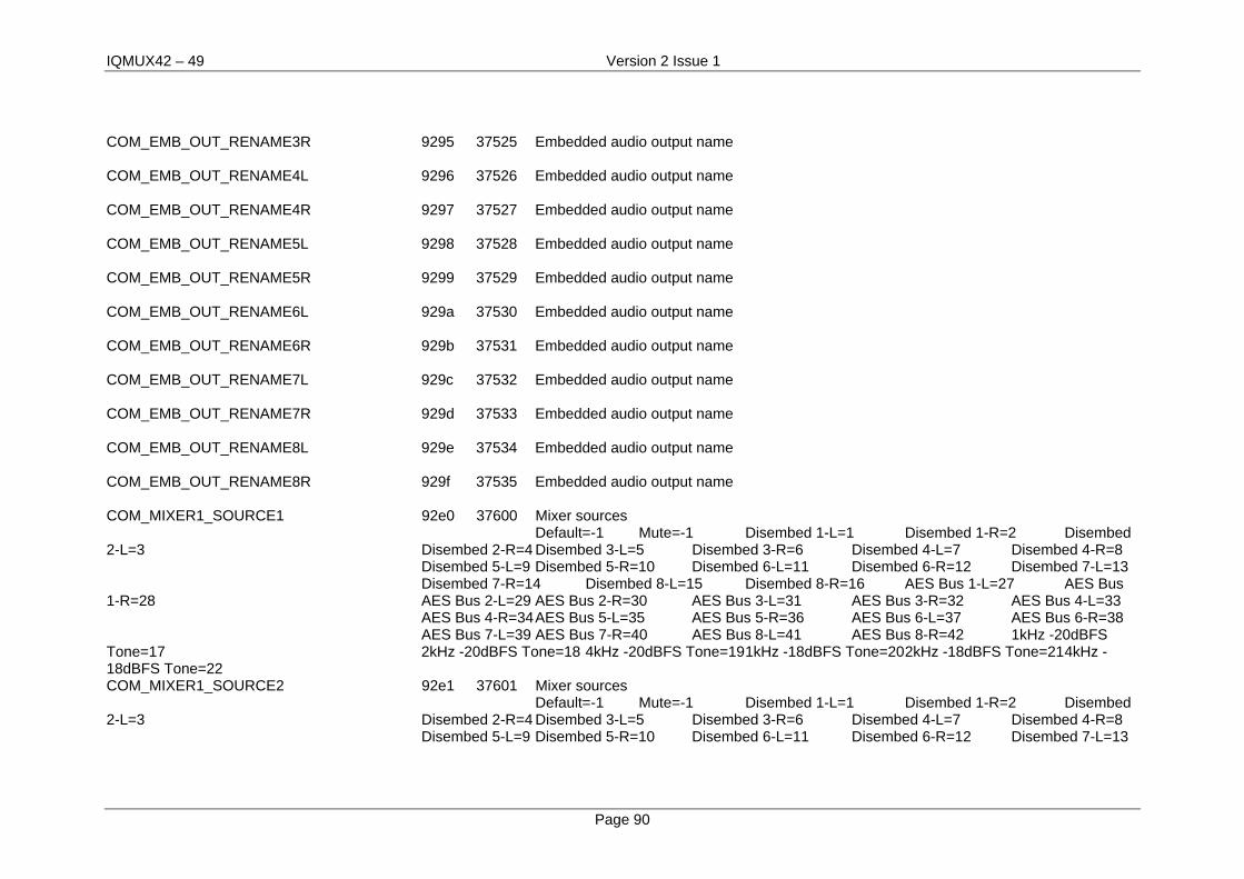
IQMUX42 – 49 Version 2 Issue 1
Page 90
COM_EMB_OUT_RENAME3R 9295 37525 Embedded audio output name COM_EMB_OUT_RENAME4L 9296 37526 Embedded audio output name COM_EMB_OUT_RENAME4R 9297 37527 Embedded audio output name COM_EMB_OUT_RENAME5L 9298 37528 Embedded audio output name COM_EMB_OUT_RENAME5R 9299 37529 Embedded audio output name COM_EMB_OUT_RENAME6L 929a 37530 Embedded audio output name COM_EMB_OUT_RENAME6R 929b 37531 Embedded audio output name COM_EMB_OUT_RENAME7L 929c 37532 Embedded audio output name COM_EMB_OUT_RENAME7R 929d 37533 Embedded audio output name COM_EMB_OUT_RENAME8L 929e 37534 Embedded audio output name COM_EMB_OUT_RENAME8R 929f 37535 Embedded audio output name COM_MIXER1_SOURCE1 92e0 37600 Mixer sources Default=-1 Mute=-1 Disembed 1-L=1 Disembed 1-R=2 Disembed 2-L=3 Disembed 2-R=4 Disembed 3-L=5 Disembed 3-R=6 Disembed 4-L=7 Disembed 4-R=8 Disembed 5-L=9 Disembed 5-R=10 Disembed 6-L=11 Disembed 6-R=12 Disembed 7-L=13 Disembed 7-R=14 Disembed 8-L=15 Disembed 8-R=16 AES Bus 1-L=27 AES Bus 1-R=28 AES Bus 2-L=29 AES Bus 2-R=30 AES Bus 3-L=31 AES Bus 3-R=32 AES Bus 4-L=33 AES Bus 4-R=34 AES Bus 5-L=35 AES Bus 5-R=36 AES Bus 6-L=37 AES Bus 6-R=38 AES Bus 7-L=39 AES Bus 7-R=40 AES Bus 8-L=41 AES Bus 8-R=42 1kHz -20dBFS Tone=17 2kHz -20dBFS Tone=18 4kHz -20dBFS Tone=19 1kHz -18dBFS Tone=20 2kHz -18dBFS Tone=21 4kHz -18dBFS Tone=22 COM_MIXER1_SOURCE2 92e1 37601 Mixer sources Default=-1 Mute=-1 Disembed 1-L=1 Disembed 1-R=2 Disembed 2-L=3 Disembed 2-R=4 Disembed 3-L=5 Disembed 3-R=6 Disembed 4-L=7 Disembed 4-R=8 Disembed 5-L=9 Disembed 5-R=10 Disembed 6-L=11 Disembed 6-R=12 Disembed 7-L=13
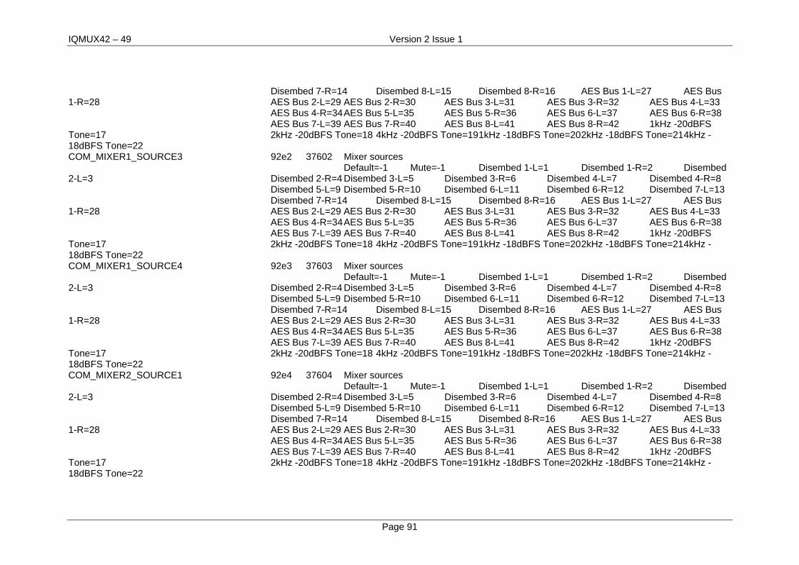
IQMUX42 – 49 Version 2 Issue 1
Page 91
Disembed 7-R=14 Disembed 8-L=15 Disembed 8-R=16 AES Bus 1-L=27 AES Bus 1-R=28 AES Bus 2-L=29 AES Bus 2-R=30 AES Bus 3-L=31 AES Bus 3-R=32 AES Bus 4-L=33 AES Bus 4-R=34 AES Bus 5-L=35 AES Bus 5-R=36 AES Bus 6-L=37 AES Bus 6-R=38 AES Bus 7-L=39 AES Bus 7-R=40 AES Bus 8-L=41 AES Bus 8-R=42 1kHz -20dBFS Tone=17 2kHz -20dBFS Tone=18 4kHz -20dBFS Tone=19 1kHz -18dBFS Tone=20 2kHz -18dBFS Tone=21 4kHz -18dBFS Tone=22 COM_MIXER1_SOURCE3 92e2 37602 Mixer sources Default=-1 Mute=-1 Disembed 1-L=1 Disembed 1-R=2 Disembed 2-L=3 Disembed 2-R=4 Disembed 3-L=5 Disembed 3-R=6 Disembed 4-L=7 Disembed 4-R=8 Disembed 5-L=9 Disembed 5-R=10 Disembed 6-L=11 Disembed 6-R=12 Disembed 7-L=13 Disembed 7-R=14 Disembed 8-L=15 Disembed 8-R=16 AES Bus 1-L=27 AES Bus 1-R=28 AES Bus 2-L=29 AES Bus 2-R=30 AES Bus 3-L=31 AES Bus 3-R=32 AES Bus 4-L=33 AES Bus 4-R=34 AES Bus 5-L=35 AES Bus 5-R=36 AES Bus 6-L=37 AES Bus 6-R=38 AES Bus 7-L=39 AES Bus 7-R=40 AES Bus 8-L=41 AES Bus 8-R=42 1kHz -20dBFS Tone=17 2kHz -20dBFS Tone=18 4kHz -20dBFS Tone=19 1kHz -18dBFS Tone=20 2kHz -18dBFS Tone=21 4kHz -18dBFS Tone=22 COM_MIXER1_SOURCE4 92e3 37603 Mixer sources Default=-1 Mute=-1 Disembed 1-L=1 Disembed 1-R=2 Disembed 2-L=3 Disembed 2-R=4 Disembed 3-L=5 Disembed 3-R=6 Disembed 4-L=7 Disembed 4-R=8 Disembed 5-L=9 Disembed 5-R=10 Disembed 6-L=11 Disembed 6-R=12 Disembed 7-L=13 Disembed 7-R=14 Disembed 8-L=15 Disembed 8-R=16 AES Bus 1-L=27 AES Bus 1-R=28 AES Bus 2-L=29 AES Bus 2-R=30 AES Bus 3-L=31 AES Bus 3-R=32 AES Bus 4-L=33 AES Bus 4-R=34 AES Bus 5-L=35 AES Bus 5-R=36 AES Bus 6-L=37 AES Bus 6-R=38 AES Bus 7-L=39 AES Bus 7-R=40 AES Bus 8-L=41 AES Bus 8-R=42 1kHz -20dBFS Tone=17 2kHz -20dBFS Tone=18 4kHz -20dBFS Tone=19 1kHz -18dBFS Tone=20 2kHz -18dBFS Tone=21 4kHz -18dBFS Tone=22 COM_MIXER2_SOURCE1 92e4 37604 Mixer sources Default=-1 Mute=-1 Disembed 1-L=1 Disembed 1-R=2 Disembed 2-L=3 Disembed 2-R=4 Disembed 3-L=5 Disembed 3-R=6 Disembed 4-L=7 Disembed 4-R=8 Disembed 5-L=9 Disembed 5-R=10 Disembed 6-L=11 Disembed 6-R=12 Disembed 7-L=13 Disembed 7-R=14 Disembed 8-L=15 Disembed 8-R=16 AES Bus 1-L=27 AES Bus 1-R=28 AES Bus 2-L=29 AES Bus 2-R=30 AES Bus 3-L=31 AES Bus 3-R=32 AES Bus 4-L=33 AES Bus 4-R=34 AES Bus 5-L=35 AES Bus 5-R=36 AES Bus 6-L=37 AES Bus 6-R=38 AES Bus 7-L=39 AES Bus 7-R=40 AES Bus 8-L=41 AES Bus 8-R=42 1kHz -20dBFS Tone=17 2kHz -20dBFS Tone=18 4kHz -20dBFS Tone=19 1kHz -18dBFS Tone=20 2kHz -18dBFS Tone=21 4kHz -18dBFS Tone=22
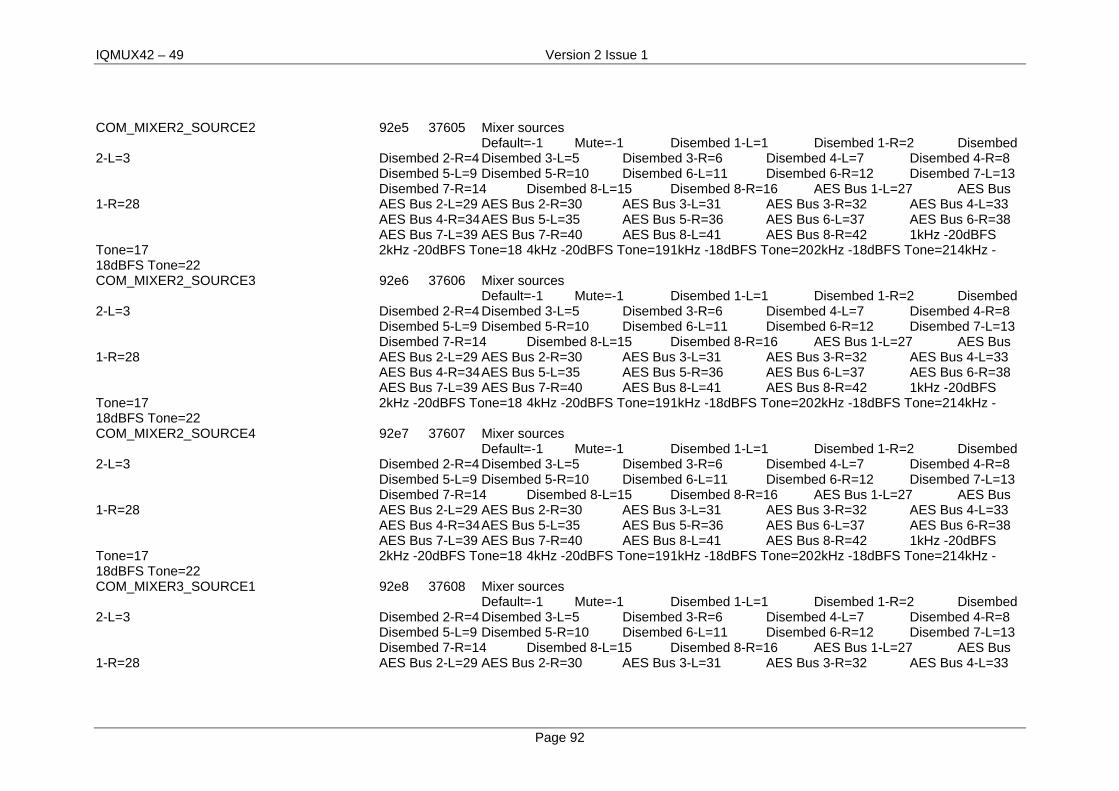
IQMUX42 – 49 Version 2 Issue 1
Page 92
COM_MIXER2_SOURCE2 92e5 37605 Mixer sources Default=-1 Mute=-1 Disembed 1-L=1 Disembed 1-R=2 Disembed 2-L=3 Disembed 2-R=4 Disembed 3-L=5 Disembed 3-R=6 Disembed 4-L=7 Disembed 4-R=8 Disembed 5-L=9 Disembed 5-R=10 Disembed 6-L=11 Disembed 6-R=12 Disembed 7-L=13 Disembed 7-R=14 Disembed 8-L=15 Disembed 8-R=16 AES Bus 1-L=27 AES Bus 1-R=28 AES Bus 2-L=29 AES Bus 2-R=30 AES Bus 3-L=31 AES Bus 3-R=32 AES Bus 4-L=33 AES Bus 4-R=34 AES Bus 5-L=35 AES Bus 5-R=36 AES Bus 6-L=37 AES Bus 6-R=38 AES Bus 7-L=39 AES Bus 7-R=40 AES Bus 8-L=41 AES Bus 8-R=42 1kHz -20dBFS Tone=17 2kHz -20dBFS Tone=18 4kHz -20dBFS Tone=19 1kHz -18dBFS Tone=20 2kHz -18dBFS Tone=21 4kHz -18dBFS Tone=22 COM_MIXER2_SOURCE3 92e6 37606 Mixer sources Default=-1 Mute=-1 Disembed 1-L=1 Disembed 1-R=2 Disembed 2-L=3 Disembed 2-R=4 Disembed 3-L=5 Disembed 3-R=6 Disembed 4-L=7 Disembed 4-R=8 Disembed 5-L=9 Disembed 5-R=10 Disembed 6-L=11 Disembed 6-R=12 Disembed 7-L=13 Disembed 7-R=14 Disembed 8-L=15 Disembed 8-R=16 AES Bus 1-L=27 AES Bus 1-R=28 AES Bus 2-L=29 AES Bus 2-R=30 AES Bus 3-L=31 AES Bus 3-R=32 AES Bus 4-L=33 AES Bus 4-R=34 AES Bus 5-L=35 AES Bus 5-R=36 AES Bus 6-L=37 AES Bus 6-R=38 AES Bus 7-L=39 AES Bus 7-R=40 AES Bus 8-L=41 AES Bus 8-R=42 1kHz -20dBFS Tone=17 2kHz -20dBFS Tone=18 4kHz -20dBFS Tone=19 1kHz -18dBFS Tone=20 2kHz -18dBFS Tone=21 4kHz -18dBFS Tone=22 COM_MIXER2_SOURCE4 92e7 37607 Mixer sources Default=-1 Mute=-1 Disembed 1-L=1 Disembed 1-R=2 Disembed 2-L=3 Disembed 2-R=4 Disembed 3-L=5 Disembed 3-R=6 Disembed 4-L=7 Disembed 4-R=8 Disembed 5-L=9 Disembed 5-R=10 Disembed 6-L=11 Disembed 6-R=12 Disembed 7-L=13 Disembed 7-R=14 Disembed 8-L=15 Disembed 8-R=16 AES Bus 1-L=27 AES Bus 1-R=28 AES Bus 2-L=29 AES Bus 2-R=30 AES Bus 3-L=31 AES Bus 3-R=32 AES Bus 4-L=33 AES Bus 4-R=34 AES Bus 5-L=35 AES Bus 5-R=36 AES Bus 6-L=37 AES Bus 6-R=38 AES Bus 7-L=39 AES Bus 7-R=40 AES Bus 8-L=41 AES Bus 8-R=42 1kHz -20dBFS Tone=17 2kHz -20dBFS Tone=18 4kHz -20dBFS Tone=19 1kHz -18dBFS Tone=20 2kHz -18dBFS Tone=21 4kHz -18dBFS Tone=22 COM_MIXER3_SOURCE1 92e8 37608 Mixer sources Default=-1 Mute=-1 Disembed 1-L=1 Disembed 1-R=2 Disembed 2-L=3 Disembed 2-R=4 Disembed 3-L=5 Disembed 3-R=6 Disembed 4-L=7 Disembed 4-R=8 Disembed 5-L=9 Disembed 5-R=10 Disembed 6-L=11 Disembed 6-R=12 Disembed 7-L=13 Disembed 7-R=14 Disembed 8-L=15 Disembed 8-R=16 AES Bus 1-L=27 AES Bus 1-R=28 AES Bus 2-L=29 AES Bus 2-R=30 AES Bus 3-L=31 AES Bus 3-R=32 AES Bus 4-L=33
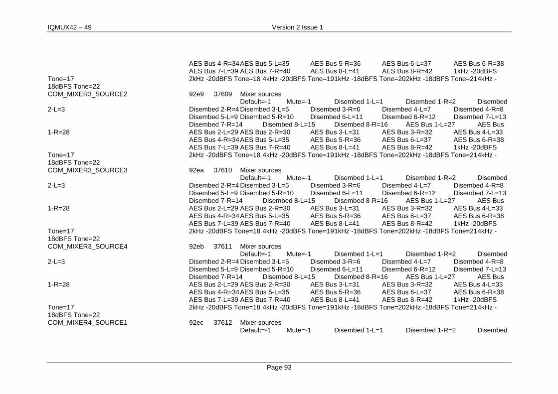
IQMUX42 – 49 Version 2 Issue 1
Page 93
AES Bus 4-R=34 AES Bus 5-L=35 AES Bus 5-R=36 AES Bus 6-L=37 AES Bus 6-R=38 AES Bus 7-L=39 AES Bus 7-R=40 AES Bus 8-L=41 AES Bus 8-R=42 1kHz -20dBFS Tone=17 2kHz -20dBFS Tone=18 4kHz -20dBFS Tone=19 1kHz -18dBFS Tone=20 2kHz -18dBFS Tone=21 4kHz -18dBFS Tone=22 COM_MIXER3_SOURCE2 92e9 37609 Mixer sources Default=-1 Mute=-1 Disembed 1-L=1 Disembed 1-R=2 Disembed 2-L=3 Disembed 2-R=4 Disembed 3-L=5 Disembed 3-R=6 Disembed 4-L=7 Disembed 4-R=8 Disembed 5-L=9 Disembed 5-R=10 Disembed 6-L=11 Disembed 6-R=12 Disembed 7-L=13 Disembed 7-R=14 Disembed 8-L=15 Disembed 8-R=16 AES Bus 1-L=27 AES Bus 1-R=28 AES Bus 2-L=29 AES Bus 2-R=30 AES Bus 3-L=31 AES Bus 3-R=32 AES Bus 4-L=33 AES Bus 4-R=34 AES Bus 5-L=35 AES Bus 5-R=36 AES Bus 6-L=37 AES Bus 6-R=38 AES Bus 7-L=39 AES Bus 7-R=40 AES Bus 8-L=41 AES Bus 8-R=42 1kHz -20dBFS Tone=17 2kHz -20dBFS Tone=18 4kHz -20dBFS Tone=19 1kHz -18dBFS Tone=20 2kHz -18dBFS Tone=21 4kHz -18dBFS Tone=22 COM_MIXER3_SOURCE3 92ea 37610 Mixer sources Default=-1 Mute=-1 Disembed 1-L=1 Disembed 1-R=2 Disembed 2-L=3 Disembed 2-R=4 Disembed 3-L=5 Disembed 3-R=6 Disembed 4-L=7 Disembed 4-R=8 Disembed 5-L=9 Disembed 5-R=10 Disembed 6-L=11 Disembed 6-R=12 Disembed 7-L=13 Disembed 7-R=14 Disembed 8-L=15 Disembed 8-R=16 AES Bus 1-L=27 AES Bus 1-R=28 AES Bus 2-L=29 AES Bus 2-R=30 AES Bus 3-L=31 AES Bus 3-R=32 AES Bus 4-L=33 AES Bus 4-R=34 AES Bus 5-L=35 AES Bus 5-R=36 AES Bus 6-L=37 AES Bus 6-R=38 AES Bus 7-L=39 AES Bus 7-R=40 AES Bus 8-L=41 AES Bus 8-R=42 1kHz -20dBFS Tone=17 2kHz -20dBFS Tone=18 4kHz -20dBFS Tone=19 1kHz -18dBFS Tone=20 2kHz -18dBFS Tone=21 4kHz -18dBFS Tone=22 COM_MIXER3_SOURCE4 92eb 37611 Mixer sources Default=-1 Mute=-1 Disembed 1-L=1 Disembed 1-R=2 Disembed 2-L=3 Disembed 2-R=4 Disembed 3-L=5 Disembed 3-R=6 Disembed 4-L=7 Disembed 4-R=8 Disembed 5-L=9 Disembed 5-R=10 Disembed 6-L=11 Disembed 6-R=12 Disembed 7-L=13 Disembed 7-R=14 Disembed 8-L=15 Disembed 8-R=16 AES Bus 1-L=27 AES Bus 1-R=28 AES Bus 2-L=29 AES Bus 2-R=30 AES Bus 3-L=31 AES Bus 3-R=32 AES Bus 4-L=33 AES Bus 4-R=34 AES Bus 5-L=35 AES Bus 5-R=36 AES Bus 6-L=37 AES Bus 6-R=38 AES Bus 7-L=39 AES Bus 7-R=40 AES Bus 8-L=41 AES Bus 8-R=42 1kHz -20dBFS Tone=17 2kHz -20dBFS Tone=18 4kHz -20dBFS Tone=19 1kHz -18dBFS Tone=20 2kHz -18dBFS Tone=21 4kHz -18dBFS Tone=22 COM_MIXER4_SOURCE1 92ec 37612 Mixer sources Default=-1 Mute=-1 Disembed 1-L=1 Disembed 1-R=2 Disembed
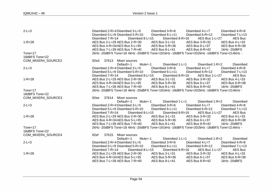
IQMUX42 – 49 Version 2 Issue 1
Page 94
2-L=3 Disembed 2-R=4 Disembed 3-L=5 Disembed 3-R=6 Disembed 4-L=7 Disembed 4-R=8 Disembed 5-L=9 Disembed 5-R=10 Disembed 6-L=11 Disembed 6-R=12 Disembed 7-L=13 Disembed 7-R=14 Disembed 8-L=15 Disembed 8-R=16 AES Bus 1-L=27 AES Bus 1-R=28 AES Bus 2-L=29 AES Bus 2-R=30 AES Bus 3-L=31 AES Bus 3-R=32 AES Bus 4-L=33 AES Bus 4-R=34 AES Bus 5-L=35 AES Bus 5-R=36 AES Bus 6-L=37 AES Bus 6-R=38 AES Bus 7-L=39 AES Bus 7-R=40 AES Bus 8-L=41 AES Bus 8-R=42 1kHz -20dBFS Tone=17 2kHz -20dBFS Tone=18 4kHz -20dBFS Tone=19 1kHz -18dBFS Tone=20 2kHz -18dBFS Tone=21 4kHz -18dBFS Tone=22 COM_MIXER4_SOURCE2 92ed 37613 Mixer sources Default=-1 Mute=-1 Disembed 1-L=1 Disembed 1-R=2 Disembed 2-L=3 Disembed 2-R=4 Disembed 3-L=5 Disembed 3-R=6 Disembed 4-L=7 Disembed 4-R=8 Disembed 5-L=9 Disembed 5-R=10 Disembed 6-L=11 Disembed 6-R=12 Disembed 7-L=13 Disembed 7-R=14 Disembed 8-L=15 Disembed 8-R=16 AES Bus 1-L=27 AES Bus 1-R=28 AES Bus 2-L=29 AES Bus 2-R=30 AES Bus 3-L=31 AES Bus 3-R=32 AES Bus 4-L=33 AES Bus 4-R=34 AES Bus 5-L=35 AES Bus 5-R=36 AES Bus 6-L=37 AES Bus 6-R=38 AES Bus 7-L=39 AES Bus 7-R=40 AES Bus 8-L=41 AES Bus 8-R=42 1kHz -20dBFS Tone=17 2kHz -20dBFS Tone=18 4kHz -20dBFS Tone=19 1kHz -18dBFS Tone=20 2kHz -18dBFS Tone=21 4kHz -18dBFS Tone=22 COM_MIXER4_SOURCE3 92ee 37614 Mixer sources Default=-1 Mute=-1 Disembed 1-L=1 Disembed 1-R=2 Disembed 2-L=3 Disembed 2-R=4 Disembed 3-L=5 Disembed 3-R=6 Disembed 4-L=7 Disembed 4-R=8 Disembed 5-L=9 Disembed 5-R=10 Disembed 6-L=11 Disembed 6-R=12 Disembed 7-L=13 Disembed 7-R=14 Disembed 8-L=15 Disembed 8-R=16 AES Bus 1-L=27 AES Bus 1-R=28 AES Bus 2-L=29 AES Bus 2-R=30 AES Bus 3-L=31 AES Bus 3-R=32 AES Bus 4-L=33 AES Bus 4-R=34 AES Bus 5-L=35 AES Bus 5-R=36 AES Bus 6-L=37 AES Bus 6-R=38 AES Bus 7-L=39 AES Bus 7-R=40 AES Bus 8-L=41 AES Bus 8-R=42 1kHz -20dBFS Tone=17 2kHz -20dBFS Tone=18 4kHz -20dBFS Tone=19 1kHz -18dBFS Tone=20 2kHz -18dBFS Tone=21 4kHz -18dBFS Tone=22 COM_MIXER4_SOURCE4 92ef 37615 Mixer sources Default=-1 Mute=-1 Disembed 1-L=1 Disembed 1-R=2 Disembed 2-L=3 Disembed 2-R=4 Disembed 3-L=5 Disembed 3-R=6 Disembed 4-L=7 Disembed 4-R=8 Disembed 5-L=9 Disembed 5-R=10 Disembed 6-L=11 Disembed 6-R=12 Disembed 7-L=13 Disembed 7-R=14 Disembed 8-L=15 Disembed 8-R=16 AES Bus 1-L=27 AES Bus 1-R=28 AES Bus 2-L=29 AES Bus 2-R=30 AES Bus 3-L=31 AES Bus 3-R=32 AES Bus 4-L=33 AES Bus 4-R=34 AES Bus 5-L=35 AES Bus 5-R=36 AES Bus 6-L=37 AES Bus 6-R=38 AES Bus 7-L=39 AES Bus 7-R=40 AES Bus 8-L=41 AES Bus 8-R=42 1kHz -20dBFS
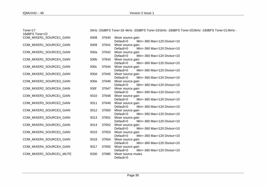
IQMUX42 – 49 Version 2 Issue 1
Page 95
Tone=17 2kHz -20dBFS Tone=18 4kHz -20dBFS Tone=19 1kHz -18dBFS Tone=20 2kHz -18dBFS Tone=21 4kHz -18dBFS Tone=22 COM_MIXER1_SOURCE1_GAIN 9308 37640 Mixer source gain Default=0 Min=-360 Max=120 Divisor=10 COM_MIXER1_SOURCE2_GAIN 9309 37641 Mixer source gain Default=0 Min=-360 Max=120 Divisor=10 COM_MIXER1_SOURCE3_GAIN 930a 37642 Mixer source gain Default=0 Min=-360 Max=120 Divisor=10 COM_MIXER1_SOURCE4_GAIN 930b 37643 Mixer source gain Default=0 Min=-360 Max=120 Divisor=10 COM_MIXER2_SOURCE1_GAIN 930c 37644 Mixer source gain Default=0 Min=-360 Max=120 Divisor=10 COM_MIXER2_SOURCE2_GAIN 930d 37645 Mixer source gain Default=0 Min=-360 Max=120 Divisor=10 COM_MIXER2_SOURCE3_GAIN 930e 37646 Mixer source gain Default=0 Min=-360 Max=120 Divisor=10 COM_MIXER2_SOURCE4_GAIN 930f 37647 Mixer source gain Default=0 Min=-360 Max=120 Divisor=10 COM_MIXER3_SOURCE1_GAIN 9310 37648 Mixer source gain Default=0 Min=-360 Max=120 Divisor=10 COM_MIXER3_SOURCE2_GAIN 9311 37649 Mixer source gain Default=0 Min=-360 Max=120 Divisor=10 COM_MIXER3_SOURCE3_GAIN 9312 37650 Mixer source gain Default=0 Min=-360 Max=120 Divisor=10 COM_MIXER3_SOURCE4_GAIN 9313 37651 Mixer source gain Default=0 Min=-360 Max=120 Divisor=10 COM_MIXER4_SOURCE1_GAIN 9314 37652 Mixer source gain Default=0 Min=-360 Max=120 Divisor=10 COM_MIXER4_SOURCE2_GAIN 9315 37653 Mixer source gain Default=0 Min=-360 Max=120 Divisor=10 COM_MIXER4_SOURCE3_GAIN 9316 37654 Mixer source gain Default=0 Min=-360 Max=120 Divisor=10 COM_MIXER4_SOURCE4_GAIN 9317 37655 Mixer source gain Default=0 Min=-360 Max=120 Divisor=10 COM_MIXER1_SOURCE1_MUTE 9330 37680 Mixer source mutes Default=0

IQMUX42 – 49 Version 2 Issue 1
Page 96
COM_MIXER1_SOURCE2_MUTE 9331 37681 Mixer source mutes Default=0 COM_MIXER1_SOURCE3_MUTE 9332 37682 Mixer source mutes Default=0 COM_MIXER1_SOURCE4_MUTE 9333 37683 Mixer source mutes Default=0 COM_MIXER2_SOURCE1_MUTE 9334 37684 Mixer source mutes Default=0 COM_MIXER2_SOURCE2_MUTE 9335 37685 Mixer source mutes Default=0 COM_MIXER2_SOURCE3_MUTE 9336 37686 Mixer source mutes Default=0 COM_MIXER2_SOURCE4_MUTE 9337 37687 Mixer source mutes Default=0 COM_MIXER3_SOURCE1_MUTE 9338 37688 Mixer source mutes Default=0 COM_MIXER3_SOURCE2_MUTE 9339 37689 Mixer source mutes Default=0 COM_MIXER3_SOURCE3_MUTE 933a 37690 Mixer source mutes Default=0 COM_MIXER3_SOURCE4_MUTE 933b 37691 Mixer source mutes Default=0 COM_MIXER4_SOURCE1_MUTE 933c 37692 Mixer source mutes Default=0 COM_MIXER4_SOURCE2_MUTE 933d 37693 Mixer source mutes Default=0 COM_MIXER4_SOURCE3_MUTE 933e 37694 Mixer source mutes Default=0 COM_MIXER4_SOURCE4_MUTE 933f 37695 Mixer source mutes Default=0 COM_MIXER1_SOURCE1_PHASE 9358 37720 Mixer source phase invert Default=0 COM_MIXER1_SOURCE2_PHASE 9359 37721 Mixer source phase invert Default=0 COM_MIXER1_SOURCE3_PHASE 935a 37722 Mixer source phase invert Default=0
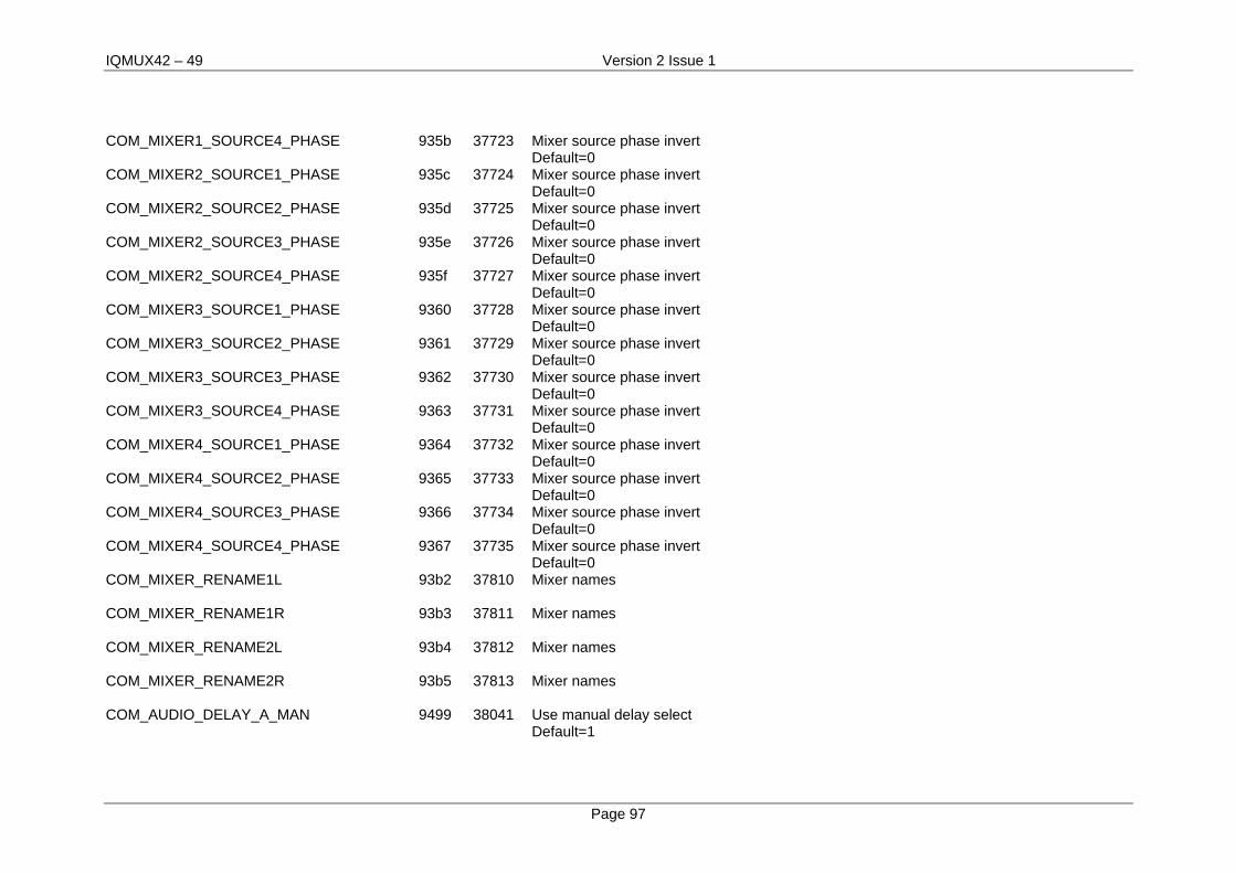
IQMUX42 – 49 Version 2 Issue 1
Page 97
COM_MIXER1_SOURCE4_PHASE 935b 37723 Mixer source phase invert Default=0 COM_MIXER2_SOURCE1_PHASE 935c 37724 Mixer source phase invert Default=0 COM_MIXER2_SOURCE2_PHASE 935d 37725 Mixer source phase invert Default=0 COM_MIXER2_SOURCE3_PHASE 935e 37726 Mixer source phase invert Default=0 COM_MIXER2_SOURCE4_PHASE 935f 37727 Mixer source phase invert Default=0 COM_MIXER3_SOURCE1_PHASE 9360 37728 Mixer source phase invert Default=0 COM_MIXER3_SOURCE2_PHASE 9361 37729 Mixer source phase invert Default=0 COM_MIXER3_SOURCE3_PHASE 9362 37730 Mixer source phase invert Default=0 COM_MIXER3_SOURCE4_PHASE 9363 37731 Mixer source phase invert Default=0 COM_MIXER4_SOURCE1_PHASE 9364 37732 Mixer source phase invert Default=0 COM_MIXER4_SOURCE2_PHASE 9365 37733 Mixer source phase invert Default=0 COM_MIXER4_SOURCE3_PHASE 9366 37734 Mixer source phase invert Default=0 COM_MIXER4_SOURCE4_PHASE 9367 37735 Mixer source phase invert Default=0 COM_MIXER_RENAME1L 93b2 37810 Mixer names COM_MIXER_RENAME1R 93b3 37811 Mixer names COM_MIXER_RENAME2L 93b4 37812 Mixer names COM_MIXER_RENAME2R 93b5 37813 Mixer names COM_AUDIO_DELAY_A_MAN 9499 38041 Use manual delay select Default=1
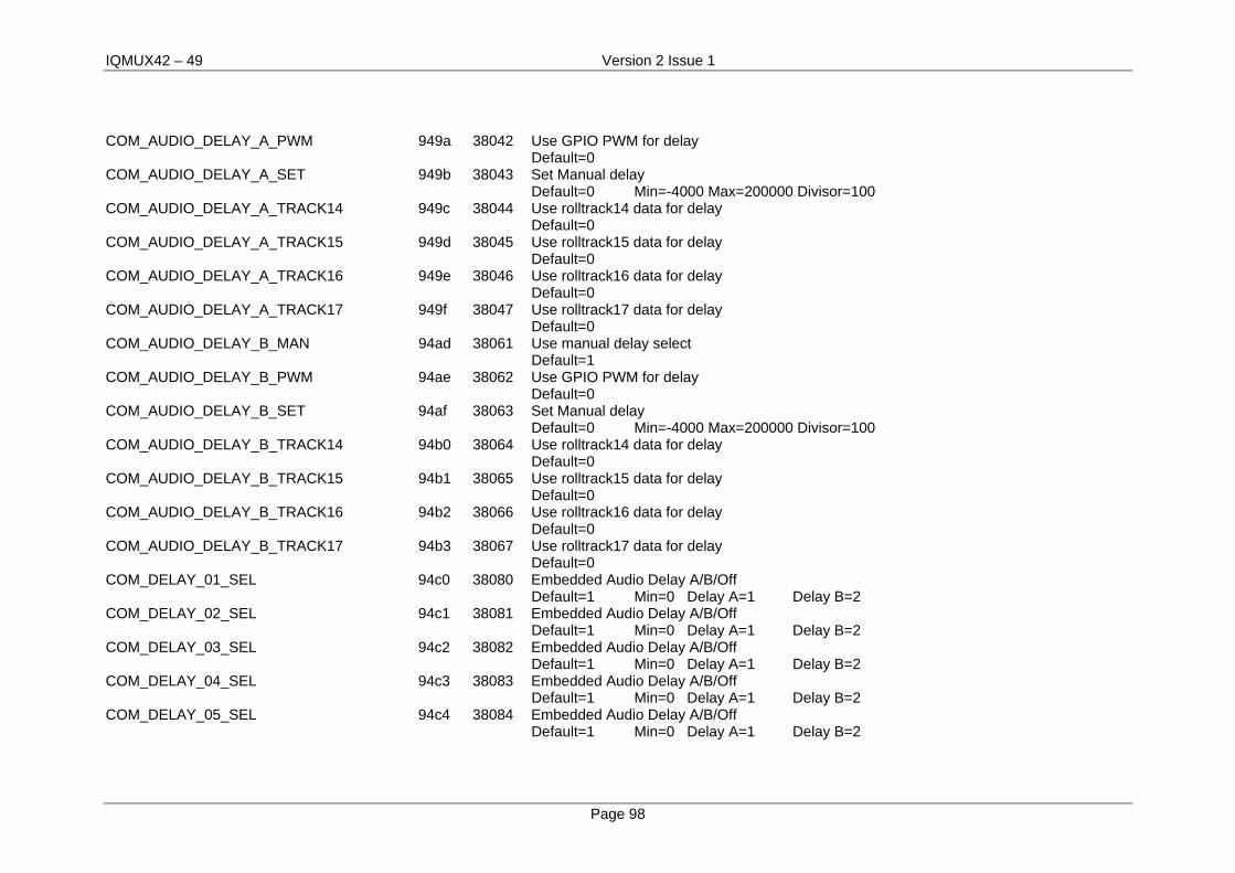
IQMUX42 – 49 Version 2 Issue 1
Page 98
COM_AUDIO_DELAY_A_PWM 949a 38042 Use GPIO PWM for delay Default=0 COM_AUDIO_DELAY_A_SET 949b 38043 Set Manual delay Default=0 Min=-4000 Max=200000 Divisor=100 COM_AUDIO_DELAY_A_TRACK14 949c 38044 Use rolltrack14 data for delay Default=0 COM_AUDIO_DELAY_A_TRACK15 949d 38045 Use rolltrack15 data for delay Default=0 COM_AUDIO_DELAY_A_TRACK16 949e 38046 Use rolltrack16 data for delay Default=0 COM_AUDIO_DELAY_A_TRACK17 949f 38047 Use rolltrack17 data for delay Default=0 COM_AUDIO_DELAY_B_MAN 94ad 38061 Use manual delay select Default=1 COM_AUDIO_DELAY_B_PWM 94ae 38062 Use GPIO PWM for delay Default=0 COM_AUDIO_DELAY_B_SET 94af 38063 Set Manual delay Default=0 Min=-4000 Max=200000 Divisor=100 COM_AUDIO_DELAY_B_TRACK14 94b0 38064 Use rolltrack14 data for delay Default=0 COM_AUDIO_DELAY_B_TRACK15 94b1 38065 Use rolltrack15 data for delay Default=0 COM_AUDIO_DELAY_B_TRACK16 94b2 38066 Use rolltrack16 data for delay Default=0 COM_AUDIO_DELAY_B_TRACK17 94b3 38067 Use rolltrack17 data for delay Default=0 COM_DELAY_01_SEL 94c0 38080 Embedded Audio Delay A/B/Off Default=1 Min=0 Delay A=1 Delay B=2 COM_DELAY_02_SEL 94c1 38081 Embedded Audio Delay A/B/Off Default=1 Min=0 Delay A=1 Delay B=2 COM_DELAY_03_SEL 94c2 38082 Embedded Audio Delay A/B/Off Default=1 Min=0 Delay A=1 Delay B=2 COM_DELAY_04_SEL 94c3 38083 Embedded Audio Delay A/B/Off Default=1 Min=0 Delay A=1 Delay B=2 COM_DELAY_05_SEL 94c4 38084 Embedded Audio Delay A/B/Off Default=1 Min=0 Delay A=1 Delay B=2
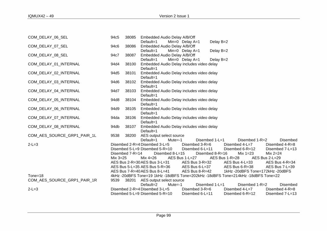
IQMUX42 – 49 Version 2 Issue 1
Page 99
COM_DELAY_06_SEL 94c5 38085 Embedded Audio Delay A/B/Off Default=1 Min=0 Delay A=1 Delay B=2 COM_DELAY_07_SEL 94c6 38086 Embedded Audio Delay A/B/Off Default=1 Min=0 Delay A=1 Delay B=2 COM_DELAY_08_SEL 94c7 38087 Embedded Audio Delay A/B/Off Default=1 Min=0 Delay A=1 Delay B=2 COM_DELAY_01_INTERNAL 94d4 38100 Embedded Audio Delay includes video delay Default=1 COM_DELAY_02_INTERNAL 94d5 38101 Embedded Audio Delay includes video delay Default=1 COM_DELAY_03_INTERNAL 94d6 38102 Embedded Audio Delay includes video delay Default=1 COM_DELAY_04_INTERNAL 94d7 38103 Embedded Audio Delay includes video delay Default=1 COM_DELAY_05_INTERNAL 94d8 38104 Embedded Audio Delay includes video delay Default=1 COM_DELAY_06_INTERNAL 94d9 38105 Embedded Audio Delay includes video delay Default=1 COM_DELAY_07_INTERNAL 94da 38106 Embedded Audio Delay includes video delay Default=1 COM_DELAY_08_INTERNAL 94db 38107 Embedded Audio Delay includes video delay Default=1 COM_AES_SOURCE_GRP1_PAIR_1L 9538 38200 AES output select source Default=1 Mute=-1 Disembed 1-L=1 Disembed 1-R=2 Disembed 2-L=3 Disembed 2-R=4 Disembed 3-L=5 Disembed 3-R=6 Disembed 4-L=7 Disembed 4-R=8 Disembed 5-L=9 Disembed 5-R=10 Disembed 6-L=11 Disembed 6-R=12 Disembed 7-L=13 Disembed 7-R=14 Disembed 8-L=15 Disembed 8-R=16 Mix 1=23 Mix 2=24 Mix 3=25 Mix 4=26 AES Bus 1-L=27 AES Bus 1-R=28 AES Bus 2-L=29 AES Bus 2-R=30 AES Bus 3-L=31 AES Bus 3-R=32 AES Bus 4-L=33 AES Bus 4-R=34 AES Bus 5-L=35 AES Bus 5-R=36 AES Bus 6-L=37 AES Bus 6-R=38 AES Bus 7-L=39 AES Bus 7-R=40 AES Bus 8-L=41 AES Bus 8-R=42 1kHz -20dBFS Tone=17 2kHz -20dBFS Tone=18 4kHz -20dBFS Tone=19 1kHz -18dBFS Tone=20 2kHz -18dBFS Tone=21 4kHz -18dBFS Tone=22 COM_AES_SOURCE_GRP1_PAIR_1R 9539 38201 AES output select source Default=2 Mute=-1 Disembed 1-L=1 Disembed 1-R=2 Disembed 2-L=3 Disembed 2-R=4 Disembed 3-L=5 Disembed 3-R=6 Disembed 4-L=7 Disembed 4-R=8 Disembed 5-L=9 Disembed 5-R=10 Disembed 6-L=11 Disembed 6-R=12 Disembed 7-L=13
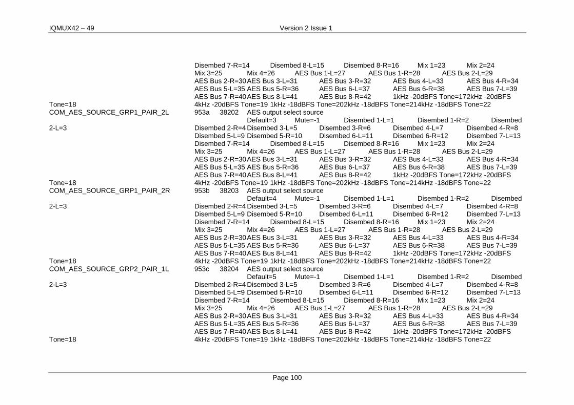
IQMUX42 – 49 Version 2 Issue 1
Page 100
Disembed 7-R=14 Disembed 8-L=15 Disembed 8-R=16 Mix 1=23 Mix 2=24 Mix 3=25 Mix 4=26 AES Bus 1-L=27 AES Bus 1-R=28 AES Bus 2-L=29 AES Bus 2-R=30 AES Bus 3-L=31 AES Bus 3-R=32 AES Bus 4-L=33 AES Bus 4-R=34 AES Bus 5-L=35 AES Bus 5-R=36 AES Bus 6-L=37 AES Bus 6-R=38 AES Bus 7-L=39 AES Bus 7-R=40 AES Bus 8-L=41 AES Bus 8-R=42 1kHz -20dBFS Tone=17 2kHz -20dBFS Tone=18 4kHz -20dBFS Tone=19 1kHz -18dBFS Tone=20 2kHz -18dBFS Tone=21 4kHz -18dBFS Tone=22 COM_AES_SOURCE_GRP1_PAIR_2L 953a 38202 AES output select source Default=3 Mute=-1 Disembed 1-L=1 Disembed 1-R=2 Disembed 2-L=3 Disembed 2-R=4 Disembed 3-L=5 Disembed 3-R=6 Disembed 4-L=7 Disembed 4-R=8 Disembed 5-L=9 Disembed 5-R=10 Disembed 6-L=11 Disembed 6-R=12 Disembed 7-L=13 Disembed 7-R=14 Disembed 8-L=15 Disembed 8-R=16 Mix 1=23 Mix 2=24 Mix 3=25 Mix 4=26 AES Bus 1-L=27 AES Bus 1-R=28 AES Bus 2-L=29 AES Bus 2-R=30 AES Bus 3-L=31 AES Bus 3-R=32 AES Bus 4-L=33 AES Bus 4-R=34 AES Bus 5-L=35 AES Bus 5-R=36 AES Bus 6-L=37 AES Bus 6-R=38 AES Bus 7-L=39 AES Bus 7-R=40 AES Bus 8-L=41 AES Bus 8-R=42 1kHz -20dBFS Tone=17 2kHz -20dBFS Tone=18 4kHz -20dBFS Tone=19 1kHz -18dBFS Tone=20 2kHz -18dBFS Tone=21 4kHz -18dBFS Tone=22 COM_AES_SOURCE_GRP1_PAIR_2R 953b 38203 AES output select source Default=4 Mute=-1 Disembed 1-L=1 Disembed 1-R=2 Disembed 2-L=3 Disembed 2-R=4 Disembed 3-L=5 Disembed 3-R=6 Disembed 4-L=7 Disembed 4-R=8 Disembed 5-L=9 Disembed 5-R=10 Disembed 6-L=11 Disembed 6-R=12 Disembed 7-L=13 Disembed 7-R=14 Disembed 8-L=15 Disembed 8-R=16 Mix 1=23 Mix 2=24 Mix 3=25 Mix 4=26 AES Bus 1-L=27 AES Bus 1-R=28 AES Bus 2-L=29 AES Bus 2-R=30 AES Bus 3-L=31 AES Bus 3-R=32 AES Bus 4-L=33 AES Bus 4-R=34 AES Bus 5-L=35 AES Bus 5-R=36 AES Bus 6-L=37 AES Bus 6-R=38 AES Bus 7-L=39 AES Bus 7-R=40 AES Bus 8-L=41 AES Bus 8-R=42 1kHz -20dBFS Tone=17 2kHz -20dBFS Tone=18 4kHz -20dBFS Tone=19 1kHz -18dBFS Tone=20 2kHz -18dBFS Tone=21 4kHz -18dBFS Tone=22 COM_AES_SOURCE_GRP2_PAIR_1L 953c 38204 AES output select source Default=5 Mute=-1 Disembed 1-L=1 Disembed 1-R=2 Disembed 2-L=3 Disembed 2-R=4 Disembed 3-L=5 Disembed 3-R=6 Disembed 4-L=7 Disembed 4-R=8 Disembed 5-L=9 Disembed 5-R=10 Disembed 6-L=11 Disembed 6-R=12 Disembed 7-L=13 Disembed 7-R=14 Disembed 8-L=15 Disembed 8-R=16 Mix 1=23 Mix 2=24 Mix 3=25 Mix 4=26 AES Bus 1-L=27 AES Bus 1-R=28 AES Bus 2-L=29 AES Bus 2-R=30 AES Bus 3-L=31 AES Bus 3-R=32 AES Bus 4-L=33 AES Bus 4-R=34 AES Bus 5-L=35 AES Bus 5-R=36 AES Bus 6-L=37 AES Bus 6-R=38 AES Bus 7-L=39 AES Bus 7-R=40 AES Bus 8-L=41 AES Bus 8-R=42 1kHz -20dBFS Tone=17 2kHz -20dBFS Tone=18 4kHz -20dBFS Tone=19 1kHz -18dBFS Tone=20 2kHz -18dBFS Tone=21 4kHz -18dBFS Tone=22
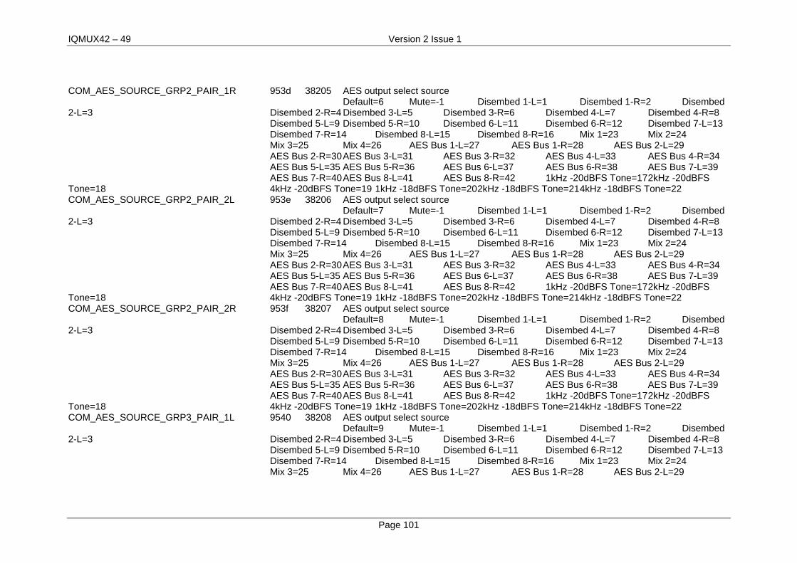
IQMUX42 – 49 Version 2 Issue 1
Page 101
COM_AES_SOURCE_GRP2_PAIR_1R 953d 38205 AES output select source Default=6 Mute=-1 Disembed 1-L=1 Disembed 1-R=2 Disembed 2-L=3 Disembed 2-R=4 Disembed 3-L=5 Disembed 3-R=6 Disembed 4-L=7 Disembed 4-R=8 Disembed 5-L=9 Disembed 5-R=10 Disembed 6-L=11 Disembed 6-R=12 Disembed 7-L=13 Disembed 7-R=14 Disembed 8-L=15 Disembed 8-R=16 Mix 1=23 Mix 2=24 Mix 3=25 Mix 4=26 AES Bus 1-L=27 AES Bus 1-R=28 AES Bus 2-L=29 AES Bus 2-R=30 AES Bus 3-L=31 AES Bus 3-R=32 AES Bus 4-L=33 AES Bus 4-R=34 AES Bus 5-L=35 AES Bus 5-R=36 AES Bus 6-L=37 AES Bus 6-R=38 AES Bus 7-L=39 AES Bus 7-R=40 AES Bus 8-L=41 AES Bus 8-R=42 1kHz -20dBFS Tone=17 2kHz -20dBFS Tone=18 4kHz -20dBFS Tone=19 1kHz -18dBFS Tone=20 2kHz -18dBFS Tone=21 4kHz -18dBFS Tone=22 COM_AES_SOURCE_GRP2_PAIR_2L 953e 38206 AES output select source Default=7 Mute=-1 Disembed 1-L=1 Disembed 1-R=2 Disembed 2-L=3 Disembed 2-R=4 Disembed 3-L=5 Disembed 3-R=6 Disembed 4-L=7 Disembed 4-R=8 Disembed 5-L=9 Disembed 5-R=10 Disembed 6-L=11 Disembed 6-R=12 Disembed 7-L=13 Disembed 7-R=14 Disembed 8-L=15 Disembed 8-R=16 Mix 1=23 Mix 2=24 Mix 3=25 Mix 4=26 AES Bus 1-L=27 AES Bus 1-R=28 AES Bus 2-L=29 AES Bus 2-R=30 AES Bus 3-L=31 AES Bus 3-R=32 AES Bus 4-L=33 AES Bus 4-R=34 AES Bus 5-L=35 AES Bus 5-R=36 AES Bus 6-L=37 AES Bus 6-R=38 AES Bus 7-L=39 AES Bus 7-R=40 AES Bus 8-L=41 AES Bus 8-R=42 1kHz -20dBFS Tone=17 2kHz -20dBFS Tone=18 4kHz -20dBFS Tone=19 1kHz -18dBFS Tone=20 2kHz -18dBFS Tone=21 4kHz -18dBFS Tone=22 COM_AES_SOURCE_GRP2_PAIR_2R 953f 38207 AES output select source Default=8 Mute=-1 Disembed 1-L=1 Disembed 1-R=2 Disembed 2-L=3 Disembed 2-R=4 Disembed 3-L=5 Disembed 3-R=6 Disembed 4-L=7 Disembed 4-R=8 Disembed 5-L=9 Disembed 5-R=10 Disembed 6-L=11 Disembed 6-R=12 Disembed 7-L=13 Disembed 7-R=14 Disembed 8-L=15 Disembed 8-R=16 Mix 1=23 Mix 2=24 Mix 3=25 Mix 4=26 AES Bus 1-L=27 AES Bus 1-R=28 AES Bus 2-L=29 AES Bus 2-R=30 AES Bus 3-L=31 AES Bus 3-R=32 AES Bus 4-L=33 AES Bus 4-R=34 AES Bus 5-L=35 AES Bus 5-R=36 AES Bus 6-L=37 AES Bus 6-R=38 AES Bus 7-L=39 AES Bus 7-R=40 AES Bus 8-L=41 AES Bus 8-R=42 1kHz -20dBFS Tone=17 2kHz -20dBFS Tone=18 4kHz -20dBFS Tone=19 1kHz -18dBFS Tone=20 2kHz -18dBFS Tone=21 4kHz -18dBFS Tone=22 COM_AES_SOURCE_GRP3_PAIR_1L 9540 38208 AES output select source Default=9 Mute=-1 Disembed 1-L=1 Disembed 1-R=2 Disembed 2-L=3 Disembed 2-R=4 Disembed 3-L=5 Disembed 3-R=6 Disembed 4-L=7 Disembed 4-R=8 Disembed 5-L=9 Disembed 5-R=10 Disembed 6-L=11 Disembed 6-R=12 Disembed 7-L=13 Disembed 7-R=14 Disembed 8-L=15 Disembed 8-R=16 Mix 1=23 Mix 2=24 Mix 3=25 Mix 4=26 AES Bus 1-L=27 AES Bus 1-R=28 AES Bus 2-L=29
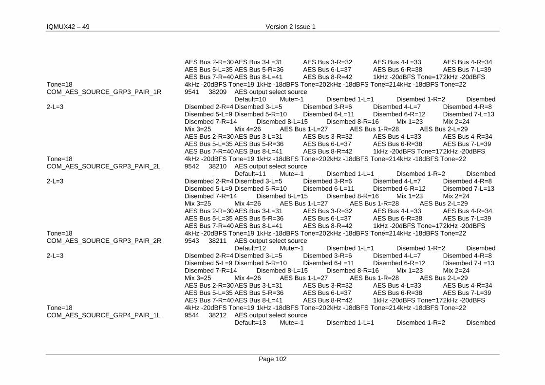
IQMUX42 – 49 Version 2 Issue 1
Page 102
AES Bus 2-R=30 AES Bus 3-L=31 AES Bus 3-R=32 AES Bus 4-L=33 AES Bus 4-R=34 AES Bus 5-L=35 AES Bus 5-R=36 AES Bus 6-L=37 AES Bus 6-R=38 AES Bus 7-L=39 AES Bus 7-R=40 AES Bus 8-L=41 AES Bus 8-R=42 1kHz -20dBFS Tone=17 2kHz -20dBFS Tone=18 4kHz -20dBFS Tone=19 1kHz -18dBFS Tone=20 2kHz -18dBFS Tone=21 4kHz -18dBFS Tone=22 COM_AES_SOURCE_GRP3_PAIR_1R 9541 38209 AES output select source Default=10 Mute=-1 Disembed 1-L=1 Disembed 1-R=2 Disembed 2-L=3 Disembed 2-R=4 Disembed 3-L=5 Disembed 3-R=6 Disembed 4-L=7 Disembed 4-R=8 Disembed 5-L=9 Disembed 5-R=10 Disembed 6-L=11 Disembed 6-R=12 Disembed 7-L=13 Disembed 7-R=14 Disembed 8-L=15 Disembed 8-R=16 Mix 1=23 Mix 2=24 Mix 3=25 Mix 4=26 AES Bus 1-L=27 AES Bus 1-R=28 AES Bus 2-L=29 AES Bus 2-R=30 AES Bus 3-L=31 AES Bus 3-R=32 AES Bus 4-L=33 AES Bus 4-R=34 AES Bus 5-L=35 AES Bus 5-R=36 AES Bus 6-L=37 AES Bus 6-R=38 AES Bus 7-L=39 AES Bus 7-R=40 AES Bus 8-L=41 AES Bus 8-R=42 1kHz -20dBFS Tone=17 2kHz -20dBFS Tone=18 4kHz -20dBFS Tone=19 1kHz -18dBFS Tone=20 2kHz -18dBFS Tone=21 4kHz -18dBFS Tone=22 COM_AES_SOURCE_GRP3_PAIR_2L 9542 38210 AES output select source Default=11 Mute=-1 Disembed 1-L=1 Disembed 1-R=2 Disembed 2-L=3 Disembed 2-R=4 Disembed 3-L=5 Disembed 3-R=6 Disembed 4-L=7 Disembed 4-R=8 Disembed 5-L=9 Disembed 5-R=10 Disembed 6-L=11 Disembed 6-R=12 Disembed 7-L=13 Disembed 7-R=14 Disembed 8-L=15 Disembed 8-R=16 Mix 1=23 Mix 2=24 Mix 3=25 Mix 4=26 AES Bus 1-L=27 AES Bus 1-R=28 AES Bus 2-L=29 AES Bus 2-R=30 AES Bus 3-L=31 AES Bus 3-R=32 AES Bus 4-L=33 AES Bus 4-R=34 AES Bus 5-L=35 AES Bus 5-R=36 AES Bus 6-L=37 AES Bus 6-R=38 AES Bus 7-L=39 AES Bus 7-R=40 AES Bus 8-L=41 AES Bus 8-R=42 1kHz -20dBFS Tone=17 2kHz -20dBFS Tone=18 4kHz -20dBFS Tone=19 1kHz -18dBFS Tone=20 2kHz -18dBFS Tone=21 4kHz -18dBFS Tone=22 COM_AES_SOURCE_GRP3_PAIR_2R 9543 38211 AES output select source Default=12 Mute=-1 Disembed 1-L=1 Disembed 1-R=2 Disembed 2-L=3 Disembed 2-R=4 Disembed 3-L=5 Disembed 3-R=6 Disembed 4-L=7 Disembed 4-R=8 Disembed 5-L=9 Disembed 5-R=10 Disembed 6-L=11 Disembed 6-R=12 Disembed 7-L=13 Disembed 7-R=14 Disembed 8-L=15 Disembed 8-R=16 Mix 1=23 Mix 2=24 Mix 3=25 Mix 4=26 AES Bus 1-L=27 AES Bus 1-R=28 AES Bus 2-L=29 AES Bus 2-R=30 AES Bus 3-L=31 AES Bus 3-R=32 AES Bus 4-L=33 AES Bus 4-R=34 AES Bus 5-L=35 AES Bus 5-R=36 AES Bus 6-L=37 AES Bus 6-R=38 AES Bus 7-L=39 AES Bus 7-R=40 AES Bus 8-L=41 AES Bus 8-R=42 1kHz -20dBFS Tone=17 2kHz -20dBFS Tone=18 4kHz -20dBFS Tone=19 1kHz -18dBFS Tone=20 2kHz -18dBFS Tone=21 4kHz -18dBFS Tone=22 COM_AES_SOURCE_GRP4_PAIR_1L 9544 38212 AES output select source Default=13 Mute=-1 Disembed 1-L=1 Disembed 1-R=2 Disembed
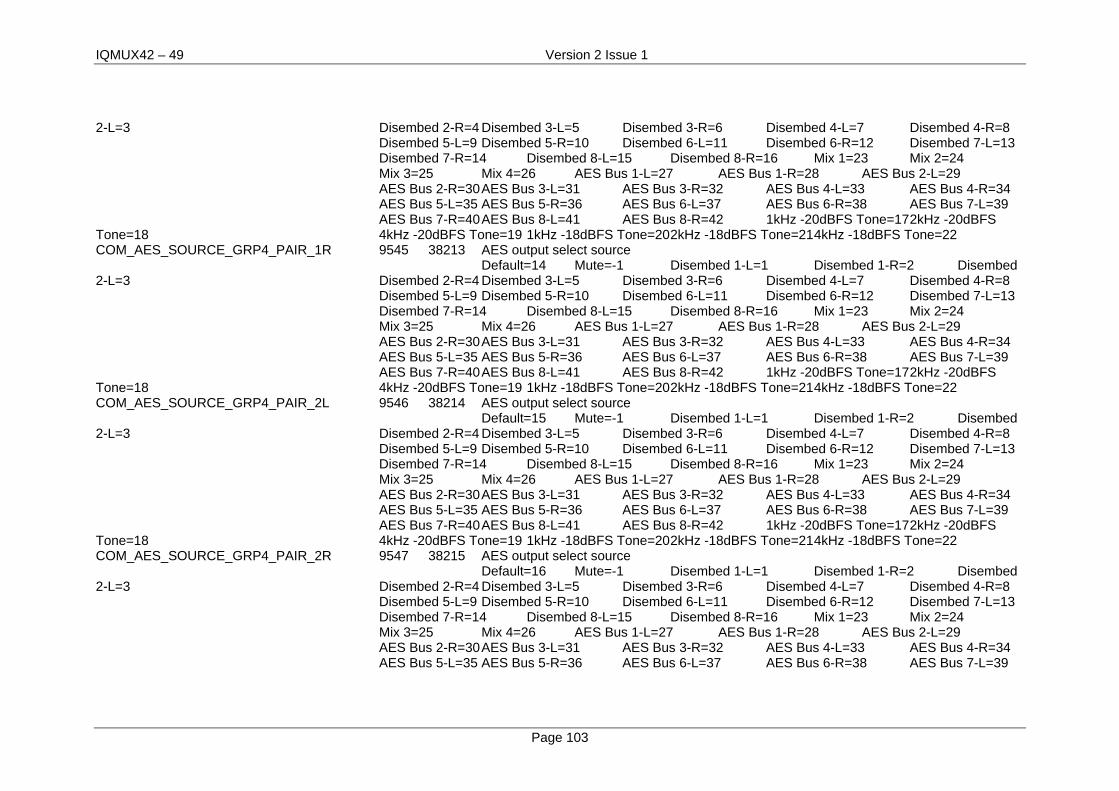
IQMUX42 – 49 Version 2 Issue 1
Page 103
2-L=3 Disembed 2-R=4 Disembed 3-L=5 Disembed 3-R=6 Disembed 4-L=7 Disembed 4-R=8 Disembed 5-L=9 Disembed 5-R=10 Disembed 6-L=11 Disembed 6-R=12 Disembed 7-L=13 Disembed 7-R=14 Disembed 8-L=15 Disembed 8-R=16 Mix 1=23 Mix 2=24 Mix 3=25 Mix 4=26 AES Bus 1-L=27 AES Bus 1-R=28 AES Bus 2-L=29 AES Bus 2-R=30 AES Bus 3-L=31 AES Bus 3-R=32 AES Bus 4-L=33 AES Bus 4-R=34 AES Bus 5-L=35 AES Bus 5-R=36 AES Bus 6-L=37 AES Bus 6-R=38 AES Bus 7-L=39 AES Bus 7-R=40 AES Bus 8-L=41 AES Bus 8-R=42 1kHz -20dBFS Tone=17 2kHz -20dBFS Tone=18 4kHz -20dBFS Tone=19 1kHz -18dBFS Tone=20 2kHz -18dBFS Tone=21 4kHz -18dBFS Tone=22 COM_AES_SOURCE_GRP4_PAIR_1R 9545 38213 AES output select source Default=14 Mute=-1 Disembed 1-L=1 Disembed 1-R=2 Disembed 2-L=3 Disembed 2-R=4 Disembed 3-L=5 Disembed 3-R=6 Disembed 4-L=7 Disembed 4-R=8 Disembed 5-L=9 Disembed 5-R=10 Disembed 6-L=11 Disembed 6-R=12 Disembed 7-L=13 Disembed 7-R=14 Disembed 8-L=15 Disembed 8-R=16 Mix 1=23 Mix 2=24 Mix 3=25 Mix 4=26 AES Bus 1-L=27 AES Bus 1-R=28 AES Bus 2-L=29 AES Bus 2-R=30 AES Bus 3-L=31 AES Bus 3-R=32 AES Bus 4-L=33 AES Bus 4-R=34 AES Bus 5-L=35 AES Bus 5-R=36 AES Bus 6-L=37 AES Bus 6-R=38 AES Bus 7-L=39 AES Bus 7-R=40 AES Bus 8-L=41 AES Bus 8-R=42 1kHz -20dBFS Tone=17 2kHz -20dBFS Tone=18 4kHz -20dBFS Tone=19 1kHz -18dBFS Tone=20 2kHz -18dBFS Tone=21 4kHz -18dBFS Tone=22 COM_AES_SOURCE_GRP4_PAIR_2L 9546 38214 AES output select source Default=15 Mute=-1 Disembed 1-L=1 Disembed 1-R=2 Disembed 2-L=3 Disembed 2-R=4 Disembed 3-L=5 Disembed 3-R=6 Disembed 4-L=7 Disembed 4-R=8 Disembed 5-L=9 Disembed 5-R=10 Disembed 6-L=11 Disembed 6-R=12 Disembed 7-L=13 Disembed 7-R=14 Disembed 8-L=15 Disembed 8-R=16 Mix 1=23 Mix 2=24 Mix 3=25 Mix 4=26 AES Bus 1-L=27 AES Bus 1-R=28 AES Bus 2-L=29 AES Bus 2-R=30 AES Bus 3-L=31 AES Bus 3-R=32 AES Bus 4-L=33 AES Bus 4-R=34 AES Bus 5-L=35 AES Bus 5-R=36 AES Bus 6-L=37 AES Bus 6-R=38 AES Bus 7-L=39 AES Bus 7-R=40 AES Bus 8-L=41 AES Bus 8-R=42 1kHz -20dBFS Tone=17 2kHz -20dBFS Tone=18 4kHz -20dBFS Tone=19 1kHz -18dBFS Tone=20 2kHz -18dBFS Tone=21 4kHz -18dBFS Tone=22 COM_AES_SOURCE_GRP4_PAIR_2R 9547 38215 AES output select source Default=16 Mute=-1 Disembed 1-L=1 Disembed 1-R=2 Disembed 2-L=3 Disembed 2-R=4 Disembed 3-L=5 Disembed 3-R=6 Disembed 4-L=7 Disembed 4-R=8 Disembed 5-L=9 Disembed 5-R=10 Disembed 6-L=11 Disembed 6-R=12 Disembed 7-L=13 Disembed 7-R=14 Disembed 8-L=15 Disembed 8-R=16 Mix 1=23 Mix 2=24 Mix 3=25 Mix 4=26 AES Bus 1-L=27 AES Bus 1-R=28 AES Bus 2-L=29 AES Bus 2-R=30 AES Bus 3-L=31 AES Bus 3-R=32 AES Bus 4-L=33 AES Bus 4-R=34 AES Bus 5-L=35 AES Bus 5-R=36 AES Bus 6-L=37 AES Bus 6-R=38 AES Bus 7-L=39
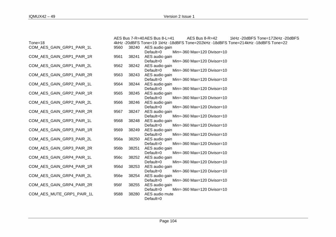
IQMUX42 – 49 Version 2 Issue 1
Page 104
AES Bus 7-R=40 AES Bus 8-L=41 AES Bus 8-R=42 1kHz -20dBFS Tone=17 2kHz -20dBFS Tone=18 4kHz -20dBFS Tone=19 1kHz -18dBFS Tone=20 2kHz -18dBFS Tone=21 4kHz -18dBFS Tone=22 COM_AES_GAIN_GRP1_PAIR_1L 9560 38240 AES audio gain Default=0 Min=-360 Max=120 Divisor=10 COM_AES_GAIN_GRP1_PAIR_1R 9561 38241 AES audio gain Default=0 Min=-360 Max=120 Divisor=10 COM_AES_GAIN_GRP1_PAIR_2L 9562 38242 AES audio gain Default=0 Min=-360 Max=120 Divisor=10 COM_AES_GAIN_GRP1_PAIR_2R 9563 38243 AES audio gain Default=0 Min=-360 Max=120 Divisor=10 COM_AES_GAIN_GRP2_PAIR_1L 9564 38244 AES audio gain Default=0 Min=-360 Max=120 Divisor=10 COM_AES_GAIN_GRP2_PAIR_1R 9565 38245 AES audio gain Default=0 Min=-360 Max=120 Divisor=10 COM_AES_GAIN_GRP2_PAIR_2L 9566 38246 AES audio gain Default=0 Min=-360 Max=120 Divisor=10 COM_AES_GAIN_GRP2_PAIR_2R 9567 38247 AES audio gain Default=0 Min=-360 Max=120 Divisor=10 COM_AES_GAIN_GRP3_PAIR_1L 9568 38248 AES audio gain Default=0 Min=-360 Max=120 Divisor=10 COM_AES_GAIN_GRP3_PAIR_1R 9569 38249 AES audio gain Default=0 Min=-360 Max=120 Divisor=10 COM_AES_GAIN_GRP3_PAIR_2L 956a 38250 AES audio gain Default=0 Min=-360 Max=120 Divisor=10 COM_AES_GAIN_GRP3_PAIR_2R 956b 38251 AES audio gain Default=0 Min=-360 Max=120 Divisor=10 COM_AES_GAIN_GRP4_PAIR_1L 956c 38252 AES audio gain Default=0 Min=-360 Max=120 Divisor=10 COM_AES_GAIN_GRP4_PAIR_1R 956d 38253 AES audio gain Default=0 Min=-360 Max=120 Divisor=10 COM_AES_GAIN_GRP4_PAIR_2L 956e 38254 AES audio gain Default=0 Min=-360 Max=120 Divisor=10 COM_AES_GAIN_GRP4_PAIR_2R 956f 38255 AES audio gain Default=0 Min=-360 Max=120 Divisor=10 COM_AES_MUTE_GRP1_PAIR_1L 9588 38280 AES audio mute Default=0
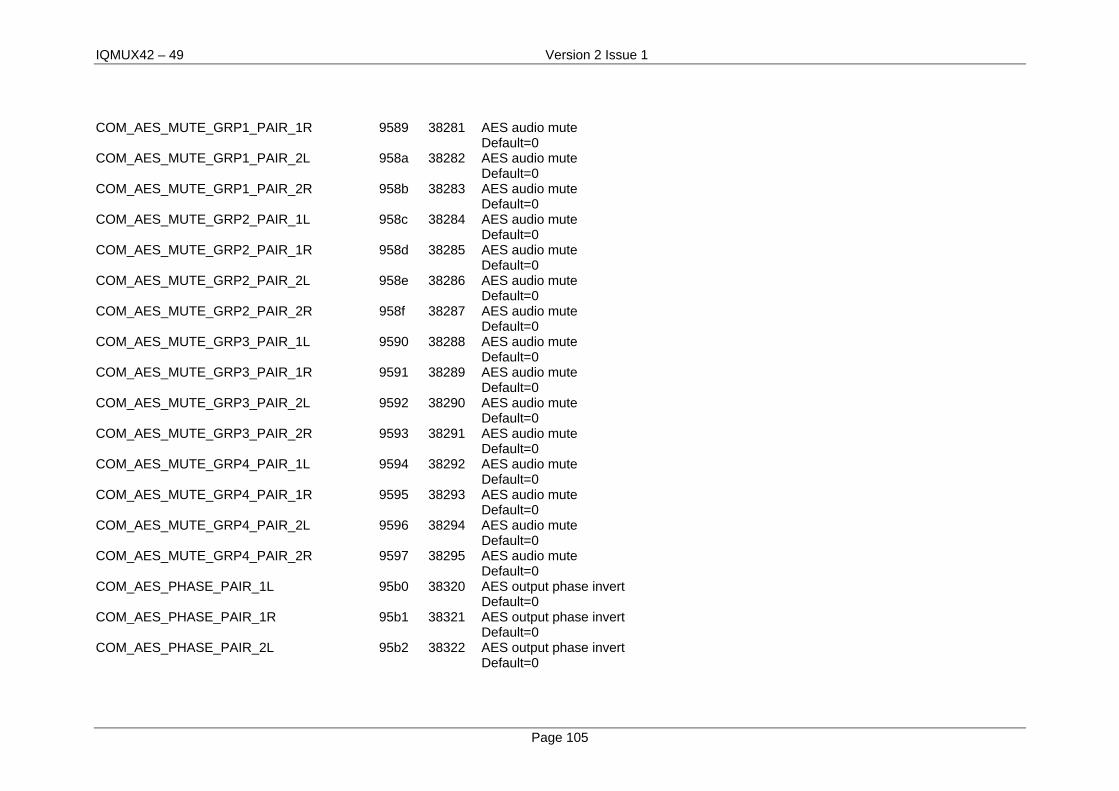
IQMUX42 – 49 Version 2 Issue 1
Page 105
COM_AES_MUTE_GRP1_PAIR_1R 9589 38281 AES audio mute Default=0 COM_AES_MUTE_GRP1_PAIR_2L 958a 38282 AES audio mute Default=0 COM_AES_MUTE_GRP1_PAIR_2R 958b 38283 AES audio mute Default=0 COM_AES_MUTE_GRP2_PAIR_1L 958c 38284 AES audio mute Default=0 COM_AES_MUTE_GRP2_PAIR_1R 958d 38285 AES audio mute Default=0 COM_AES_MUTE_GRP2_PAIR_2L 958e 38286 AES audio mute Default=0 COM_AES_MUTE_GRP2_PAIR_2R 958f 38287 AES audio mute Default=0 COM_AES_MUTE_GRP3_PAIR_1L 9590 38288 AES audio mute Default=0 COM_AES_MUTE_GRP3_PAIR_1R 9591 38289 AES audio mute Default=0 COM_AES_MUTE_GRP3_PAIR_2L 9592 38290 AES audio mute Default=0 COM_AES_MUTE_GRP3_PAIR_2R 9593 38291 AES audio mute Default=0 COM_AES_MUTE_GRP4_PAIR_1L 9594 38292 AES audio mute Default=0 COM_AES_MUTE_GRP4_PAIR_1R 9595 38293 AES audio mute Default=0 COM_AES_MUTE_GRP4_PAIR_2L 9596 38294 AES audio mute Default=0 COM_AES_MUTE_GRP4_PAIR_2R 9597 38295 AES audio mute Default=0 COM_AES_PHASE_PAIR_1L 95b0 38320 AES output phase invert Default=0 COM_AES_PHASE_PAIR_1R 95b1 38321 AES output phase invert Default=0 COM_AES_PHASE_PAIR_2L 95b2 38322 AES output phase invert Default=0
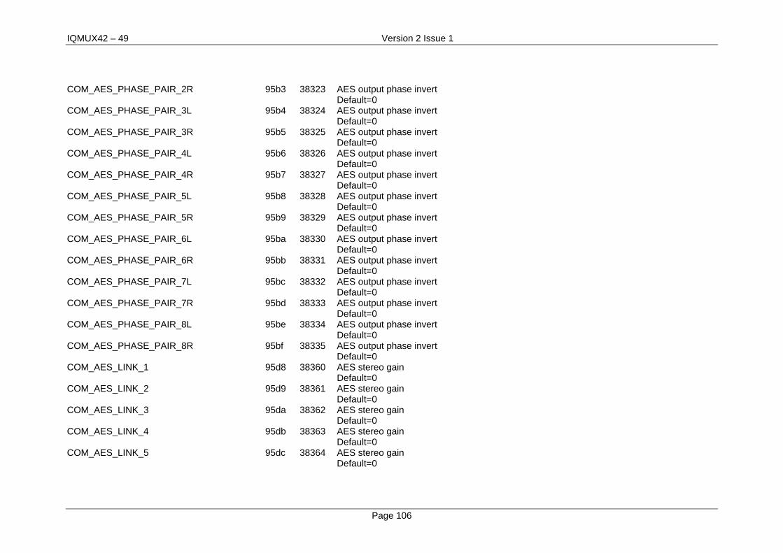
IQMUX42 – 49 Version 2 Issue 1
Page 106
COM_AES_PHASE_PAIR_2R 95b3 38323 AES output phase invert Default=0 COM_AES_PHASE_PAIR_3L 95b4 38324 AES output phase invert Default=0 COM_AES_PHASE_PAIR_3R 95b5 38325 AES output phase invert Default=0 COM_AES_PHASE_PAIR_4L 95b6 38326 AES output phase invert Default=0 COM_AES_PHASE_PAIR_4R 95b7 38327 AES output phase invert Default=0 COM_AES_PHASE_PAIR_5L 95b8 38328 AES output phase invert Default=0 COM_AES_PHASE_PAIR_5R 95b9 38329 AES output phase invert Default=0 COM_AES_PHASE_PAIR_6L 95ba 38330 AES output phase invert Default=0 COM_AES_PHASE_PAIR_6R 95bb 38331 AES output phase invert Default=0 COM_AES_PHASE_PAIR_7L 95bc 38332 AES output phase invert Default=0 COM_AES_PHASE_PAIR_7R 95bd 38333 AES output phase invert Default=0 COM_AES_PHASE_PAIR_8L 95be 38334 AES output phase invert Default=0 COM_AES_PHASE_PAIR_8R 95bf 38335 AES output phase invert Default=0 COM_AES_LINK_1 95d8 38360 AES stereo gain Default=0 COM_AES_LINK_2 95d9 38361 AES stereo gain Default=0 COM_AES_LINK_3 95da 38362 AES stereo gain Default=0 COM_AES_LINK_4 95db 38363 AES stereo gain Default=0 COM_AES_LINK_5 95dc 38364 AES stereo gain Default=0
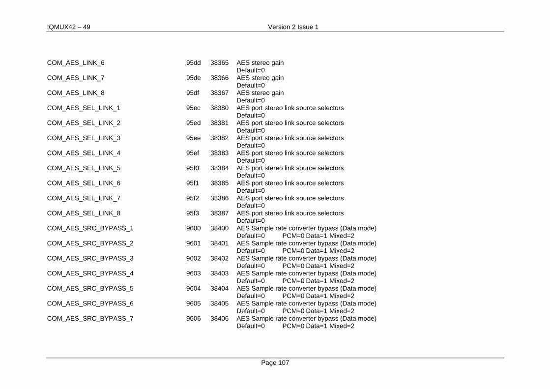
IQMUX42 – 49 Version 2 Issue 1
Page 107
COM_AES_LINK_6 95dd 38365 AES stereo gain Default=0 COM_AES_LINK_7 95de 38366 AES stereo gain Default=0 COM_AES_LINK_8 95df 38367 AES stereo gain Default=0 COM_AES_SEL_LINK_1 95ec 38380 AES port stereo link source selectors Default=0 COM_AES_SEL_LINK_2 95ed 38381 AES port stereo link source selectors Default=0 COM_AES_SEL_LINK_3 95ee 38382 AES port stereo link source selectors Default=0 COM_AES_SEL_LINK_4 95ef 38383 AES port stereo link source selectors Default=0 COM_AES_SEL_LINK_5 95f0 38384 AES port stereo link source selectors Default=0 COM_AES_SEL_LINK_6 95f1 38385 AES port stereo link source selectors Default=0 COM_AES_SEL_LINK_7 95f2 38386 AES port stereo link source selectors Default=0 COM_AES_SEL_LINK_8 95f3 38387 AES port stereo link source selectors Default=0 COM_AES_SRC_BYPASS_1 9600 38400 AES Sample rate converter bypass (Data mode) Default=0 PCM=0 Data=1 Mixed=2 COM_AES_SRC_BYPASS_2 9601 38401 AES Sample rate converter bypass (Data mode) Default=0 PCM=0 Data=1 Mixed=2 COM_AES_SRC_BYPASS_3 9602 38402 AES Sample rate converter bypass (Data mode) Default=0 PCM=0 Data=1 Mixed=2 COM_AES_SRC_BYPASS_4 9603 38403 AES Sample rate converter bypass (Data mode) Default=0 PCM=0 Data=1 Mixed=2 COM_AES_SRC_BYPASS_5 9604 38404 AES Sample rate converter bypass (Data mode) Default=0 PCM=0 Data=1 Mixed=2 COM_AES_SRC_BYPASS_6 9605 38405 AES Sample rate converter bypass (Data mode) Default=0 PCM=0 Data=1 Mixed=2 COM_AES_SRC_BYPASS_7 9606 38406 AES Sample rate converter bypass (Data mode) Default=0 PCM=0 Data=1 Mixed=2
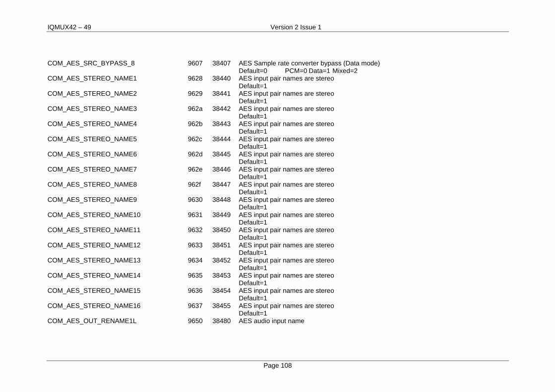
IQMUX42 – 49 Version 2 Issue 1
Page 108
COM_AES_SRC_BYPASS_8 9607 38407 AES Sample rate converter bypass (Data mode) Default=0 PCM=0 Data=1 Mixed=2 COM_AES_STEREO_NAME1 9628 38440 AES input pair names are stereo Default=1 COM_AES_STEREO_NAME2 9629 38441 AES input pair names are stereo Default=1 COM_AES_STEREO_NAME3 962a 38442 AES input pair names are stereo Default=1 COM_AES_STEREO_NAME4 962b 38443 AES input pair names are stereo Default=1 COM_AES_STEREO_NAME5 962c 38444 AES input pair names are stereo Default=1 COM_AES_STEREO_NAME6 962d 38445 AES input pair names are stereo Default=1 COM_AES_STEREO_NAME7 962e 38446 AES input pair names are stereo Default=1 COM_AES_STEREO_NAME8 962f 38447 AES input pair names are stereo Default=1 COM_AES_STEREO_NAME9 9630 38448 AES input pair names are stereo Default=1 COM_AES_STEREO_NAME10 9631 38449 AES input pair names are stereo Default=1 COM_AES_STEREO_NAME11 9632 38450 AES input pair names are stereo Default=1 COM_AES_STEREO_NAME12 9633 38451 AES input pair names are stereo Default=1 COM_AES_STEREO_NAME13 9634 38452 AES input pair names are stereo Default=1 COM_AES_STEREO_NAME14 9635 38453 AES input pair names are stereo Default=1 COM_AES_STEREO_NAME15 9636 38454 AES input pair names are stereo Default=1 COM_AES_STEREO_NAME16 9637 38455 AES input pair names are stereo Default=1 COM_AES_OUT_RENAME1L 9650 38480 AES audio input name
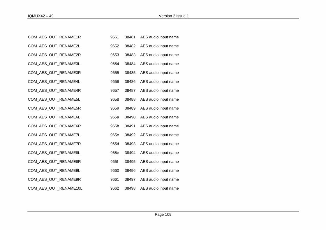
IQMUX42 – 49 Version 2 Issue 1
Page 109
COM_AES_OUT_RENAME1R 9651 38481 AES audio input name COM_AES_OUT_RENAME2L 9652 38482 AES audio input name COM_AES_OUT_RENAME2R 9653 38483 AES audio input name COM_AES_OUT_RENAME3L 9654 38484 AES audio input name COM_AES_OUT_RENAME3R 9655 38485 AES audio input name COM_AES_OUT_RENAME4L 9656 38486 AES audio input name COM_AES_OUT_RENAME4R 9657 38487 AES audio input name COM_AES_OUT_RENAME5L 9658 38488 AES audio input name COM_AES_OUT_RENAME5R 9659 38489 AES audio input name COM_AES_OUT_RENAME6L 965a 38490 AES audio input name COM_AES_OUT_RENAME6R 965b 38491 AES audio input name COM_AES_OUT_RENAME7L 965c 38492 AES audio input name COM_AES_OUT_RENAME7R 965d 38493 AES audio input name COM_AES_OUT_RENAME8L 965e 38494 AES audio input name COM_AES_OUT_RENAME8R 965f 38495 AES audio input name COM_AES_OUT_RENAME9L 9660 38496 AES audio input name COM_AES_OUT_RENAME9R 9661 38497 AES audio input name COM_AES_OUT_RENAME10L 9662 38498 AES audio input name
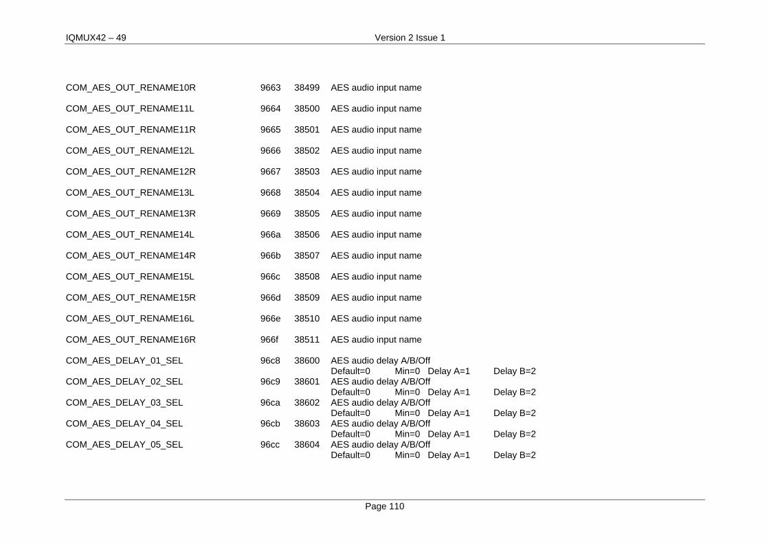
IQMUX42 – 49 Version 2 Issue 1
Page 110
COM_AES_OUT_RENAME10R 9663 38499 AES audio input name COM_AES_OUT_RENAME11L 9664 38500 AES audio input name COM_AES_OUT_RENAME11R 9665 38501 AES audio input name COM_AES_OUT_RENAME12L 9666 38502 AES audio input name COM_AES_OUT_RENAME12R 9667 38503 AES audio input name COM_AES_OUT_RENAME13L 9668 38504 AES audio input name COM_AES_OUT_RENAME13R 9669 38505 AES audio input name COM_AES_OUT_RENAME14L 966a 38506 AES audio input name COM_AES_OUT_RENAME14R 966b 38507 AES audio input name COM_AES_OUT_RENAME15L 966c 38508 AES audio input name COM_AES_OUT_RENAME15R 966d 38509 AES audio input name COM_AES_OUT_RENAME16L 966e 38510 AES audio input name COM_AES_OUT_RENAME16R 966f 38511 AES audio input name COM_AES_DELAY_01_SEL 96c8 38600 AES audio delay A/B/Off Default=0 Min=0 Delay A=1 Delay B=2 COM_AES_DELAY_02_SEL 96c9 38601 AES audio delay A/B/Off Default=0 Min=0 Delay A=1 Delay B=2 COM_AES_DELAY_03_SEL 96ca 38602 AES audio delay A/B/Off Default=0 Min=0 Delay A=1 Delay B=2 COM_AES_DELAY_04_SEL 96cb 38603 AES audio delay A/B/Off Default=0 Min=0 Delay A=1 Delay B=2 COM_AES_DELAY_05_SEL 96cc 38604 AES audio delay A/B/Off Default=0 Min=0 Delay A=1 Delay B=2
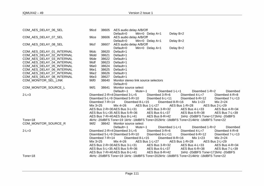
IQMUX42 – 49 Version 2 Issue 1
Page 111
COM_AES_DELAY_06_SEL 96cd 38605 AES audio delay A/B/Off Default=0 Min=0 Delay A=1 Delay B=2 COM_AES_DELAY_07_SEL 96ce 38606 AES audio delay A/B/Off Default=0 Min=0 Delay A=1 Delay B=2 COM_AES_DELAY_08_SEL 96cf 38607 AES audio delay A/B/Off Default=0 Min=0 Delay A=1 Delay B=2 COM_AES_DELAY_01_INTERNAL 96dc 38620 Default=1 COM_AES_DELAY_02_INTERNAL 96dd 38621 Default=1 COM_AES_DELAY_03_INTERNAL 96de 38622 Default=1 COM_AES_DELAY_04_INTERNAL 96df 38623 Default=1 COM_AES_DELAY_05_INTERNAL 96e0 38624 Default=1 COM_AES_DELAY_06_INTERNAL 96e1 38625 Default=1 COM_AES_DELAY_07_INTERNAL 96e2 38626 Default=1 COM_AES_DELAY_08_INTERNAL 96e3 38627 Default=1 COM_MONITOR_SEL_LINK 96f0 38640 Monitor stereo link source selectors Default=0 COM_MONITOR_SOURCE_L 96f1 38641 Monitor source select Default=-1 Mute=-1 Disembed 1-L=1 Disembed 1-R=2 Disembed 2-L=3 Disembed 2-R=4 Disembed 3-L=5 Disembed 3-R=6 Disembed 4-L=7 Disembed 4-R=8 Disembed 5-L=9 Disembed 5-R=10 Disembed 6-L=11 Disembed 6-R=12 Disembed 7-L=13 Disembed 7-R=14 Disembed 8-L=15 Disembed 8-R=16 Mix 1=23 Mix 2=24 Mix 3=25 Mix 4=26 AES Bus 1-L=27 AES Bus 1-R=28 AES Bus 2-L=29 AES Bus 2-R=30 AES Bus 3-L=31 AES Bus 3-R=32 AES Bus 4-L=33 AES Bus 4-R=34 AES Bus 5-L=35 AES Bus 5-R=36 AES Bus 6-L=37 AES Bus 6-R=38 AES Bus 7-L=39 AES Bus 7-R=40 AES Bus 8-L=41 AES Bus 8-R=42 1kHz -20dBFS Tone=17 2kHz -20dBFS Tone=18 4kHz -20dBFS Tone=19 1kHz -18dBFS Tone=20 2kHz -18dBFS Tone=21 4kHz -18dBFS Tone=22 COM_MONITOR_SOURCE_R 96f2 38642 Monitor source select Default=-1 Mute=-1 Disembed 1-L=1 Disembed 1-R=2 Disembed 2-L=3 Disembed 2-R=4 Disembed 3-L=5 Disembed 3-R=6 Disembed 4-L=7 Disembed 4-R=8 Disembed 5-L=9 Disembed 5-R=10 Disembed 6-L=11 Disembed 6-R=12 Disembed 7-L=13 Disembed 7-R=14 Disembed 8-L=15 Disembed 8-R=16 Mix 1=23 Mix 2=24 Mix 3=25 Mix 4=26 AES Bus 1-L=27 AES Bus 1-R=28 AES Bus 2-L=29 AES Bus 2-R=30 AES Bus 3-L=31 AES Bus 3-R=32 AES Bus 4-L=33 AES Bus 4-R=34 AES Bus 5-L=35 AES Bus 5-R=36 AES Bus 6-L=37 AES Bus 6-R=38 AES Bus 7-L=39 AES Bus 7-R=40 AES Bus 8-L=41 AES Bus 8-R=42 1kHz -20dBFS Tone=17 2kHz -20dBFS Tone=18 4kHz -20dBFS Tone=19 1kHz -18dBFS Tone=20 2kHz -18dBFS Tone=21 4kHz -18dBFS Tone=22
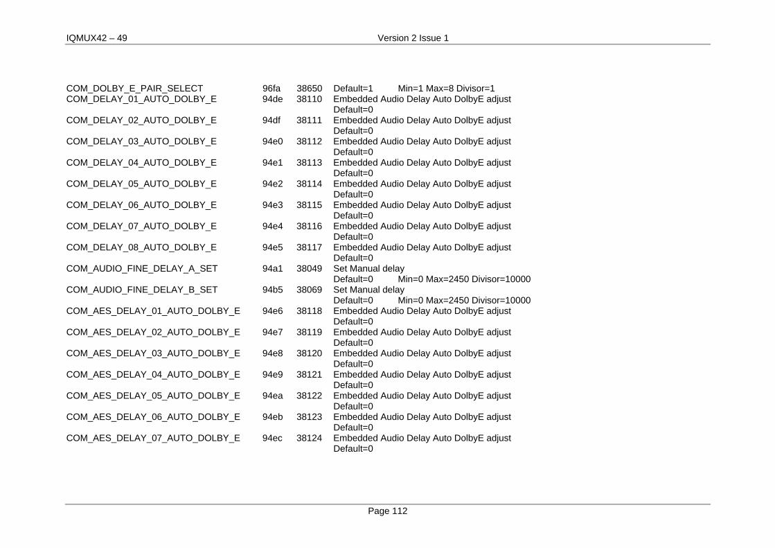
IQMUX42 – 49 Version 2 Issue 1
Page 112
COM_DOLBY_E_PAIR_SELECT 96fa 38650 Default=1 Min=1 Max=8 Divisor=1 COM_DELAY_01_AUTO_DOLBY_E 94de 38110 Embedded Audio Delay Auto DolbyE adjust Default=0 COM_DELAY_02_AUTO_DOLBY_E 94df 38111 Embedded Audio Delay Auto DolbyE adjust Default=0 COM_DELAY_03_AUTO_DOLBY_E 94e0 38112 Embedded Audio Delay Auto DolbyE adjust Default=0 COM_DELAY_04_AUTO_DOLBY_E 94e1 38113 Embedded Audio Delay Auto DolbyE adjust Default=0 COM_DELAY_05_AUTO_DOLBY_E 94e2 38114 Embedded Audio Delay Auto DolbyE adjust Default=0 COM_DELAY_06_AUTO_DOLBY_E 94e3 38115 Embedded Audio Delay Auto DolbyE adjust Default=0 COM_DELAY_07_AUTO_DOLBY_E 94e4 38116 Embedded Audio Delay Auto DolbyE adjust Default=0 COM_DELAY_08_AUTO_DOLBY_E 94e5 38117 Embedded Audio Delay Auto DolbyE adjust Default=0 COM_AUDIO_FINE_DELAY_A_SET 94a1 38049 Set Manual delay Default=0 Min=0 Max=2450 Divisor=10000 COM_AUDIO_FINE_DELAY_B_SET 94b5 38069 Set Manual delay Default=0 Min=0 Max=2450 Divisor=10000 COM_AES_DELAY_01_AUTO_DOLBY_E 94e6 38118 Embedded Audio Delay Auto DolbyE adjust Default=0 COM_AES_DELAY_02_AUTO_DOLBY_E 94e7 38119 Embedded Audio Delay Auto DolbyE adjust Default=0 COM_AES_DELAY_03_AUTO_DOLBY_E 94e8 38120 Embedded Audio Delay Auto DolbyE adjust Default=0 COM_AES_DELAY_04_AUTO_DOLBY_E 94e9 38121 Embedded Audio Delay Auto DolbyE adjust Default=0 COM_AES_DELAY_05_AUTO_DOLBY_E 94ea 38122 Embedded Audio Delay Auto DolbyE adjust Default=0 COM_AES_DELAY_06_AUTO_DOLBY_E 94eb 38123 Embedded Audio Delay Auto DolbyE adjust Default=0 COM_AES_DELAY_07_AUTO_DOLBY_E 94ec 38124 Embedded Audio Delay Auto DolbyE adjust Default=0
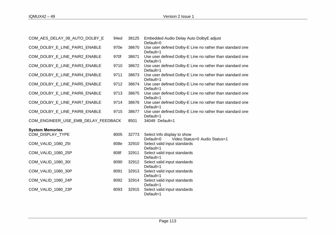
IQMUX42 – 49 Version 2 Issue 1
Page 113
COM_AES_DELAY_08_AUTO_DOLBY_E 94ed 38125 Embedded Audio Delay Auto DolbyE adjust Default=0 COM_DOLBY_E_LINE_PAIR1_ENABLE 970e 38670 Use user defined Dolby-E Line no rather than standard one Default=1 COM_DOLBY_E_LINE_PAIR2_ENABLE 970f 38671 Use user defined Dolby-E Line no rather than standard one Default=1 COM_DOLBY_E_LINE_PAIR3_ENABLE 9710 38672 Use user defined Dolby-E Line no rather than standard one Default=1 COM_DOLBY_E_LINE_PAIR4_ENABLE 9711 38673 Use user defined Dolby-E Line no rather than standard one Default=1 COM_DOLBY_E_LINE_PAIR5_ENABLE 9712 38674 Use user defined Dolby-E Line no rather than standard one Default=1 COM_DOLBY_E_LINE_PAIR6_ENABLE 9713 38675 Use user defined Dolby-E Line no rather than standard one Default=1 COM_DOLBY_E_LINE_PAIR7_ENABLE 9714 38676 Use user defined Dolby-E Line no rather than standard one Default=1 COM_DOLBY_E_LINE_PAIR8_ENABLE 9715 38677 Use user defined Dolby-E Line no rather than standard one Default=1 COM_ENGINEER_USE_EMB_DELAY_FEEDBACK 8501 34049 Default=1 System Memories COM_DISPLAY_TYPE 8005 32773 Select Info display to show Default=0 Video Status=0 Audio Status=1 COM_VALID_1080_25I 808e 32910 Select valid input standards Default=1 COM_VALID_1080_25P 808f 32911 Select valid input standards Default=1 COM_VALID_1080_30I 8090 32912 Select valid input standards Default=1 COM_VALID_1080_30P 8091 32913 Select valid input standards Default=1 COM_VALID_1080_24P 8092 32914 Select valid input standards Default=1 COM_VALID_1080_23P 8093 32915 Select valid input standards Default=1
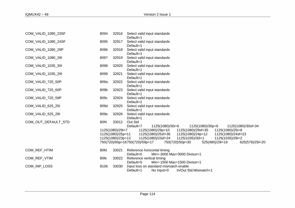
IQMUX42 – 49 Version 2 Issue 1
Page 114
COM_VALID_1080_23SF 8094 32916 Select valid input standards Default=1 COM_VALID_1080_24SF 8095 32917 Select valid input standards Default=1 COM_VALID_1080_29P 8096 32918 Select valid input standards Default=1 COM_VALID_1080_29I 8097 32919 Select valid input standards Default=1 COM_VALID_1035_30I 8098 32920 Select valid input standards Default=1 COM_VALID_1035_29I 8099 32921 Select valid input standards Default=1 COM_VALID_720_50P 809a 32922 Select valid input standards Default=1 COM_VALID_720_60P 809b 32923 Select valid input standards Default=1 COM_VALID_720_59P 809c 32924 Select valid input standards Default=1 COM_VALID_625_25I 809d 32925 Select valid input standards Default=1 COM_VALID_525_29I 809e 32926 Select valid input standards Default=1 COM_OUT_DEFAULT_STD 80f4 33012 Out Std Default=7 1125(1080)/30i=6 1125(1080)/30p=9 1125(1080)/30sf=34 1125(1080)/29i=7 1125(1080)/29p=10 1125(1080)/29sf=35 1125(1080)/25i=8 1125(1080)/25p=11 1125(1080)/25sf=36 1125(1080)/24p=12 1125(1080)/24sf=23 1125(1080)/23p=13 1125(1080)/23sf=24 1125(1035)/30i=1 1125(1035)/29i=2 750(720)/60p=16 750(720)/59p=17 750(720)/50p=30 525(480)/29i=19 625(576)/25i=20 COM_REF_HTIM 80fd 33021 Reference horizontal timing Default=0 Min=-3000 Max=3000 Divisor=1 COM_REF_VTIM 80fe 33022 Reference vertical timing Default=0 Min=-1500 Max=1500 Divisor=1 COM_INP_LOSS 8106 33030 Input loss on standard mismatch enable Default=1 No Input=0 In/Out Std.Mismatch=1
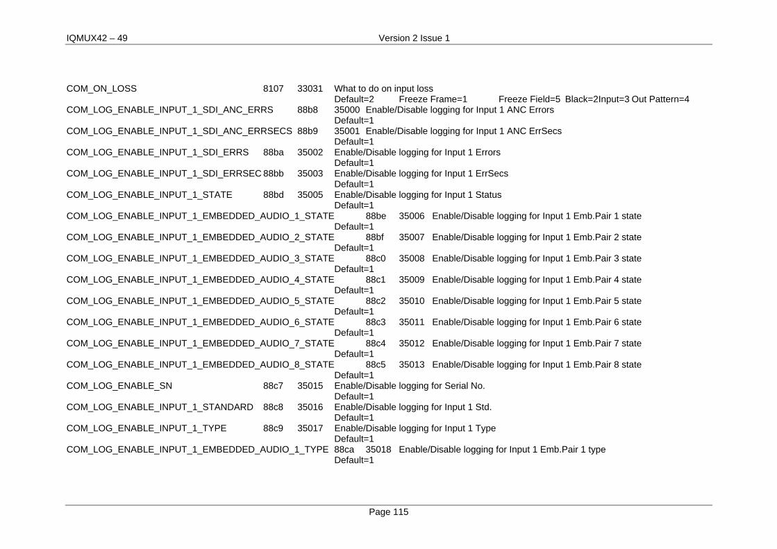
IQMUX42 – 49 Version 2 Issue 1
Page 115
COM_ON_LOSS 8107 33031 What to do on input loss Default=2 Freeze Frame=1 Freeze Field=5 Black=2 Input=3 Out Pattern=4 COM_LOG_ENABLE_INPUT_1_SDI_ANC_ERRS 88b8 35000 Enable/Disable logging for Input 1 ANC Errors Default=1 COM_LOG_ENABLE_INPUT_1_SDI_ANC_ERRSECS 88b9 35001 Enable/Disable logging for Input 1 ANC ErrSecs Default=1 COM_LOG_ENABLE_INPUT_1_SDI_ERRS 88ba 35002 Enable/Disable logging for Input 1 Errors Default=1 COM_LOG_ENABLE_INPUT_1_SDI_ERRSEC 88bb 35003 Enable/Disable logging for Input 1 ErrSecs Default=1 COM_LOG_ENABLE_INPUT_1_STATE 88bd 35005 Enable/Disable logging for Input 1 Status Default=1 COM_LOG_ENABLE_INPUT_1_EMBEDDED_AUDIO_1_STATE 88be 35006 Enable/Disable logging for Input 1 Emb.Pair 1 state Default=1 COM_LOG_ENABLE_INPUT_1_EMBEDDED_AUDIO_2_STATE 88bf 35007 Enable/Disable logging for Input 1 Emb.Pair 2 state Default=1 COM_LOG_ENABLE_INPUT_1_EMBEDDED_AUDIO_3_STATE 88c0 35008 Enable/Disable logging for Input 1 Emb.Pair 3 state Default=1 COM_LOG_ENABLE_INPUT_1_EMBEDDED_AUDIO_4_STATE 88c1 35009 Enable/Disable logging for Input 1 Emb.Pair 4 state Default=1 COM_LOG_ENABLE_INPUT_1_EMBEDDED_AUDIO_5_STATE 88c2 35010 Enable/Disable logging for Input 1 Emb.Pair 5 state Default=1 COM_LOG_ENABLE_INPUT_1_EMBEDDED_AUDIO_6_STATE 88c3 35011 Enable/Disable logging for Input 1 Emb.Pair 6 state Default=1 COM_LOG_ENABLE_INPUT_1_EMBEDDED_AUDIO_7_STATE 88c4 35012 Enable/Disable logging for Input 1 Emb.Pair 7 state Default=1 COM_LOG_ENABLE_INPUT_1_EMBEDDED_AUDIO_8_STATE 88c5 35013 Enable/Disable logging for Input 1 Emb.Pair 8 state Default=1 COM_LOG_ENABLE_SN 88c7 35015 Enable/Disable logging for Serial No. Default=1 COM_LOG_ENABLE_INPUT_1_STANDARD 88c8 35016 Enable/Disable logging for Input 1 Std. Default=1 COM_LOG_ENABLE_INPUT_1_TYPE 88c9 35017 Enable/Disable logging for Input 1 Type Default=1 COM_LOG_ENABLE_INPUT_1_EMBEDDED_AUDIO_1_TYPE 88ca 35018 Enable/Disable logging for Input 1 Emb.Pair 1 type Default=1
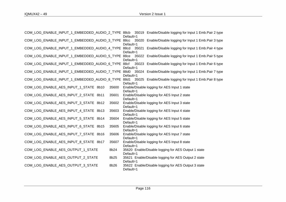
IQMUX42 – 49 Version 2 Issue 1
Page 116
COM_LOG_ENABLE_INPUT_1_EMBEDDED_AUDIO_2_TYPE 88cb 35019 Enable/Disable logging for Input 1 Emb.Pair 2 type Default=1 COM_LOG_ENABLE_INPUT_1_EMBEDDED_AUDIO_3_TYPE 88cc 35020 Enable/Disable logging for Input 1 Emb.Pair 3 type Default=1 COM_LOG_ENABLE_INPUT_1_EMBEDDED_AUDIO_4_TYPE 88cd 35021 Enable/Disable logging for Input 1 Emb.Pair 4 type Default=1 COM_LOG_ENABLE_INPUT_1_EMBEDDED_AUDIO_5_TYPE 88ce 35022 Enable/Disable logging for Input 1 Emb.Pair 5 type Default=1 COM_LOG_ENABLE_INPUT_1_EMBEDDED_AUDIO_6_TYPE 88cf 35023 Enable/Disable logging for Input 1 Emb.Pair 6 type Default=1 COM_LOG_ENABLE_INPUT_1_EMBEDDED_AUDIO_7_TYPE 88d0 35024 Enable/Disable logging for Input 1 Emb.Pair 7 type Default=1 COM_LOG_ENABLE_INPUT_1_EMBEDDED_AUDIO_8_TYPE 88d1 35025 Enable/Disable logging for Input 1 Emb.Pair 8 type Default=1 COM_LOG_ENABLE_AES_INPUT_1_STATE 8b10 35600 Enable/Disable logging for AES Input 1 state Default=1 COM_LOG_ENABLE_AES_INPUT_2_STATE 8b11 35601 Enable/Disable logging for AES Input 2 state Default=1 COM_LOG_ENABLE_AES_INPUT_3_STATE 8b12 35602 Enable/Disable logging for AES Input 3 state Default=1 COM_LOG_ENABLE_AES_INPUT_4_STATE 8b13 35603 Enable/Disable logging for AES Input 4 state Default=1 COM_LOG_ENABLE_AES_INPUT_5_STATE 8b14 35604 Enable/Disable logging for AES Input 5 state Default=1 COM_LOG_ENABLE_AES_INPUT_6_STATE 8b15 35605 Enable/Disable logging for AES Input 6 state Default=1 COM_LOG_ENABLE_AES_INPUT_7_STATE 8b16 35606 Enable/Disable logging for AES Input 7 state Default=1 COM_LOG_ENABLE_AES_INPUT_8_STATE 8b17 35607 Enable/Disable logging for AES Input 8 state Default=1 COM_LOG_ENABLE_AES_OUTPUT_1_STATE 8b24 35620 Enable/Disable logging for AES Output 1 state Default=1 COM_LOG_ENABLE_AES_OUTPUT_2_STATE 8b25 35621 Enable/Disable logging for AES Output 2 state Default=1 COM_LOG_ENABLE_AES_OUTPUT_3_STATE 8b26 35622 Enable/Disable logging for AES Output 3 state Default=1
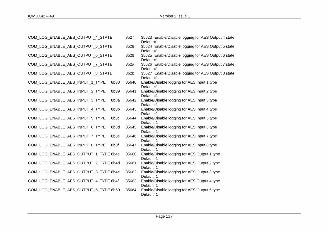
IQMUX42 – 49 Version 2 Issue 1
Page 117
COM_LOG_ENABLE_AES_OUTPUT_4_STATE 8b27 35623 Enable/Disable logging for AES Output 4 state Default=1 COM_LOG_ENABLE_AES_OUTPUT_5_STATE 8b28 35624 Enable/Disable logging for AES Output 5 state Default=1 COM_LOG_ENABLE_AES_OUTPUT_6_STATE 8b29 35625 Enable/Disable logging for AES Output 6 state Default=1 COM_LOG_ENABLE_AES_OUTPUT_7_STATE 8b2a 35626 Enable/Disable logging for AES Output 7 state Default=1 COM_LOG_ENABLE_AES_OUTPUT_8_STATE 8b2b 35627 Enable/Disable logging for AES Output 8 state Default=1 COM_LOG_ENABLE_AES_INPUT_1_TYPE 8b38 35640 Enable/Disable logging for AES Input 1 type Default=1 COM_LOG_ENABLE_AES_INPUT_2_TYPE 8b39 35641 Enable/Disable logging for AES Input 2 type Default=1 COM_LOG_ENABLE_AES_INPUT_3_TYPE 8b3a 35642 Enable/Disable logging for AES Input 3 type Default=1 COM_LOG_ENABLE_AES_INPUT_4_TYPE 8b3b 35643 Enable/Disable logging for AES Input 4 type Default=1 COM_LOG_ENABLE_AES_INPUT_5_TYPE 8b3c 35644 Enable/Disable logging for AES Input 5 type Default=1 COM_LOG_ENABLE_AES_INPUT_6_TYPE 8b3d 35645 Enable/Disable logging for AES Input 6 type Default=1 COM_LOG_ENABLE_AES_INPUT_7_TYPE 8b3e 35646 Enable/Disable logging for AES Input 7 type Default=1 COM_LOG_ENABLE_AES_INPUT_8_TYPE 8b3f 35647 Enable/Disable logging for AES Input 8 type Default=1 COM_LOG_ENABLE_AES_OUTPUT_1_TYPE 8b4c 35660 Enable/Disable logging for AES Output 1 type Default=1 COM_LOG_ENABLE_AES_OUTPUT_2_TYPE 8b4d 35661 Enable/Disable logging for AES Output 2 type Default=1 COM_LOG_ENABLE_AES_OUTPUT_3_TYPE 8b4e 35662 Enable/Disable logging for AES Output 3 type Default=1 COM_LOG_ENABLE_AES_OUTPUT_4_TYPE 8b4f 35663 Enable/Disable logging for AES Output 4 type Default=1 COM_LOG_ENABLE_AES_OUTPUT_5_TYPE 8b50 35664 Enable/Disable logging for AES Output 5 type Default=1
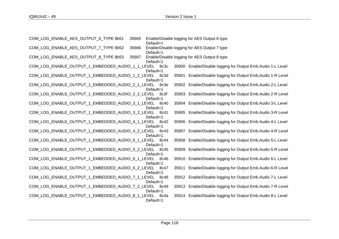
IQMUX42 – 49 Version 2 Issue 1
Page 118
COM_LOG_ENABLE_AES_OUTPUT_6_TYPE 8b51 35665 Enable/Disable logging for AES Output 6 type Default=1 COM_LOG_ENABLE_AES_OUTPUT_7_TYPE 8b52 35666 Enable/Disable logging for AES Output 7 type Default=1 COM_LOG_ENABLE_AES_OUTPUT_8_TYPE 8b53 35667 Enable/Disable logging for AES Output 8 type Default=1 COM_LOG_ENABLE_OUTPUT_1_EMBEDDED_AUDIO_1_1_LEVEL 8c3c 35900 Enable/Disable logging for Output Emb.Audio 1-L Level Default=1 COM_LOG_ENABLE_OUTPUT_1_EMBEDDED_AUDIO_1_2_LEVEL 8c3d 35901 Enable/Disable logging for Output Emb.Audio 1-R Level Default=1 COM_LOG_ENABLE_OUTPUT_1_EMBEDDED_AUDIO_2_1_LEVEL 8c3e 35902 Enable/Disable logging for Output Emb.Audio 2-L Level Default=1 COM_LOG_ENABLE_OUTPUT_1_EMBEDDED_AUDIO_2_2_LEVEL 8c3f 35903 Enable/Disable logging for Output Emb.Audio 2-R Level Default=1 COM_LOG_ENABLE_OUTPUT_1_EMBEDDED_AUDIO_3_1_LEVEL 8c40 35904 Enable/Disable logging for Output Emb.Audio 3-L Level Default=1 COM_LOG_ENABLE_OUTPUT_1_EMBEDDED_AUDIO_3_2_LEVEL 8c41 35905 Enable/Disable logging for Output Emb.Audio 3-R Level Default=1 COM_LOG_ENABLE_OUTPUT_1_EMBEDDED_AUDIO_4_1_LEVEL 8c42 35906 Enable/Disable logging for Output Emb.Audio 4-L Level Default=1 COM_LOG_ENABLE_OUTPUT_1_EMBEDDED_AUDIO_4_2_LEVEL 8c43 35907 Enable/Disable logging for Output Emb.Audio 4-R Level Default=1 COM_LOG_ENABLE_OUTPUT_1_EMBEDDED_AUDIO_5_1_LEVEL 8c44 35908 Enable/Disable logging for Output Emb.Audio 5-L Level Default=1 COM_LOG_ENABLE_OUTPUT_1_EMBEDDED_AUDIO_5_2_LEVEL 8c45 35909 Enable/Disable logging for Output Emb.Audio 5-R Level Default=1 COM_LOG_ENABLE_OUTPUT_1_EMBEDDED_AUDIO_6_1_LEVEL 8c46 35910 Enable/Disable logging for Output Emb.Audio 6-L Level Default=1 COM_LOG_ENABLE_OUTPUT_1_EMBEDDED_AUDIO_6_2_LEVEL 8c47 35911 Enable/Disable logging for Output Emb.Audio 6-R Level Default=1 COM_LOG_ENABLE_OUTPUT_1_EMBEDDED_AUDIO_7_1_LEVEL 8c48 35912 Enable/Disable logging for Output Emb.Audio 7-L Level Default=1 COM_LOG_ENABLE_OUTPUT_1_EMBEDDED_AUDIO_7_2_LEVEL 8c49 35913 Enable/Disable logging for Output Emb.Audio 7-R Level Default=1 COM_LOG_ENABLE_OUTPUT_1_EMBEDDED_AUDIO_8_1_LEVEL 8c4a 35914 Enable/Disable logging for Output Emb.Audio 8-L Level Default=1
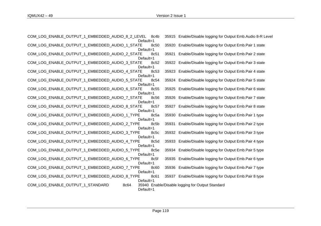
IQMUX42 – 49 Version 2 Issue 1
Page 119
COM_LOG_ENABLE_OUTPUT_1_EMBEDDED_AUDIO_8_2_LEVEL 8c4b 35915 Enable/Disable logging for Output Emb.Audio 8-R Level Default=1 COM_LOG_ENABLE_OUTPUT_1_EMBEDDED_AUDIO_1_STATE 8c50 35920 Enable/Disable logging for Output Emb.Pair 1 state Default=1 COM_LOG_ENABLE_OUTPUT_1_EMBEDDED_AUDIO_2_STATE 8c51 35921 Enable/Disable logging for Output Emb.Pair 2 state Default=1 COM_LOG_ENABLE_OUTPUT_1_EMBEDDED_AUDIO_3_STATE 8c52 35922 Enable/Disable logging for Output Emb.Pair 3 state Default=1 COM_LOG_ENABLE_OUTPUT_1_EMBEDDED_AUDIO_4_STATE 8c53 35923 Enable/Disable logging for Output Emb.Pair 4 state Default=1 COM_LOG_ENABLE_OUTPUT_1_EMBEDDED_AUDIO_5_STATE 8c54 35924 Enable/Disable logging for Output Emb.Pair 5 state Default=1 COM_LOG_ENABLE_OUTPUT_1_EMBEDDED_AUDIO_6_STATE 8c55 35925 Enable/Disable logging for Output Emb.Pair 6 state Default=1 COM_LOG_ENABLE_OUTPUT_1_EMBEDDED_AUDIO_7_STATE 8c56 35926 Enable/Disable logging for Output Emb.Pair 7 state Default=1 COM_LOG_ENABLE_OUTPUT_1_EMBEDDED_AUDIO_8_STATE 8c57 35927 Enable/Disable logging for Output Emb.Pair 8 state Default=1 COM_LOG_ENABLE_OUTPUT_1_EMBEDDED_AUDIO_1_TYPE 8c5a 35930 Enable/Disable logging for Output Emb.Pair 1 type Default=1 COM_LOG_ENABLE_OUTPUT_1_EMBEDDED_AUDIO_2_TYPE 8c5b 35931 Enable/Disable logging for Output Emb.Pair 2 type Default=1 COM_LOG_ENABLE_OUTPUT_1_EMBEDDED_AUDIO_3_TYPE 8c5c 35932 Enable/Disable logging for Output Emb.Pair 3 type Default=1 COM_LOG_ENABLE_OUTPUT_1_EMBEDDED_AUDIO_4_TYPE 8c5d 35933 Enable/Disable logging for Output Emb.Pair 4 type Default=1 COM_LOG_ENABLE_OUTPUT_1_EMBEDDED_AUDIO_5_TYPE 8c5e 35934 Enable/Disable logging for Output Emb.Pair 5 type Default=1 COM_LOG_ENABLE_OUTPUT_1_EMBEDDED_AUDIO_6_TYPE 8c5f 35935 Enable/Disable logging for Output Emb.Pair 6 type Default=1 COM_LOG_ENABLE_OUTPUT_1_EMBEDDED_AUDIO_7_TYPE 8c60 35936 Enable/Disable logging for Output Emb.Pair 7 type Default=1 COM_LOG_ENABLE_OUTPUT_1_EMBEDDED_AUDIO_8_TYPE 8c61 35937 Enable/Disable logging for Output Emb.Pair 8 type Default=1 COM_LOG_ENABLE_OUTPUT_1_STANDARD 8c64 35940 Enable/Disable logging for Output Standard Default=1
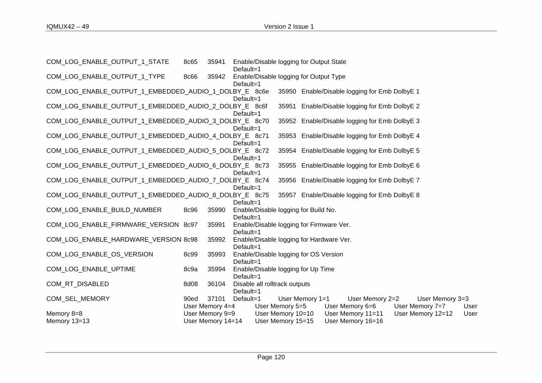
IQMUX42 – 49 Version 2 Issue 1
Page 120
COM_LOG_ENABLE_OUTPUT_1_STATE 8c65 35941 Enable/Disable logging for Output State Default=1 COM_LOG_ENABLE_OUTPUT_1_TYPE 8c66 35942 Enable/Disable logging for Output Type Default=1 COM_LOG_ENABLE_OUTPUT_1_EMBEDDED_AUDIO_1_DOLBY_E 8c6e 35950 Enable/Disable logging for Emb DolbyE 1 Default=1 COM_LOG_ENABLE_OUTPUT_1_EMBEDDED_AUDIO_2_DOLBY_E 8c6f 35951 Enable/Disable logging for Emb DolbyE 2 Default=1 COM_LOG_ENABLE_OUTPUT_1_EMBEDDED_AUDIO_3_DOLBY_E 8c70 35952 Enable/Disable logging for Emb DolbyE 3 Default=1 COM_LOG_ENABLE_OUTPUT_1_EMBEDDED_AUDIO_4_DOLBY_E 8c71 35953 Enable/Disable logging for Emb DolbyE 4 Default=1 COM_LOG_ENABLE_OUTPUT_1_EMBEDDED_AUDIO_5_DOLBY_E 8c72 35954 Enable/Disable logging for Emb DolbyE 5 Default=1 COM_LOG_ENABLE_OUTPUT_1_EMBEDDED_AUDIO_6_DOLBY_E 8c73 35955 Enable/Disable logging for Emb DolbyE 6 Default=1 COM_LOG_ENABLE_OUTPUT_1_EMBEDDED_AUDIO_7_DOLBY_E 8c74 35956 Enable/Disable logging for Emb DolbyE 7 Default=1 COM_LOG_ENABLE_OUTPUT_1_EMBEDDED_AUDIO_8_DOLBY_E 8c75 35957 Enable/Disable logging for Emb DolbyE 8 Default=1 COM_LOG_ENABLE_BUILD_NUMBER 8c96 35990 Enable/Disable logging for Build No. Default=1 COM_LOG_ENABLE_FIRMWARE_VERSION 8c97 35991 Enable/Disable logging for Firmware Ver. Default=1 COM_LOG_ENABLE_HARDWARE_VERSION 8c98 35992 Enable/Disable logging for Hardware Ver. Default=1 COM_LOG_ENABLE_OS_VERSION 8c99 35993 Enable/Disable logging for OS Version Default=1 COM_LOG_ENABLE_UPTIME 8c9a 35994 Enable/Disable logging for Up Time Default=1 COM_RT_DISABLED 8d08 36104 Disable all rolltrack outputs Default=1 COM_SEL_MEMORY 90ed 37101 Default=1 User Memory 1=1 User Memory 2=2 User Memory 3=3 User Memory 4=4 User Memory 5=5 User Memory 6=6 User Memory 7=7 User Memory 8=8 User Memory 9=9 User Memory 10=10 User Memory 11=11 User Memory 12=12 User Memory 13=13 User Memory 14=14 User Memory 15=15 User Memory 16=16
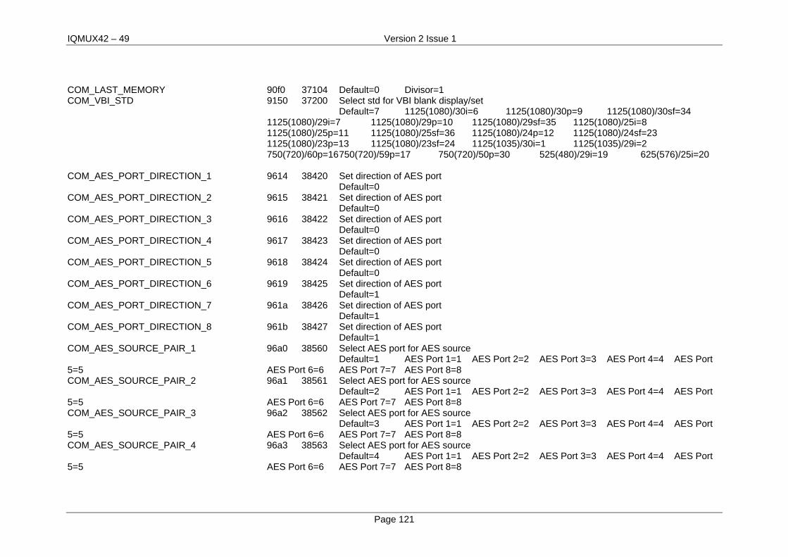
IQMUX42 – 49 Version 2 Issue 1
Page 121
COM_LAST_MEMORY 90f0 37104 Default=0 Divisor=1 COM_VBI_STD 9150 37200 Select std for VBI blank display/set Default=7 1125(1080)/30i=6 1125(1080)/30p=9 1125(1080)/30sf=34 1125(1080)/29i=7 1125(1080)/29p=10 1125(1080)/29sf=35 1125(1080)/25i=8 1125(1080)/25p=11 1125(1080)/25sf=36 1125(1080)/24p=12 1125(1080)/24sf=23 1125(1080)/23p=13 1125(1080)/23sf=24 1125(1035)/30i=1 1125(1035)/29i=2 750(720)/60p=16 750(720)/59p=17 750(720)/50p=30 525(480)/29i=19 625(576)/25i=20 COM_AES_PORT_DIRECTION_1 9614 38420 Set direction of AES port Default=0 COM_AES_PORT_DIRECTION_2 9615 38421 Set direction of AES port Default=0 COM_AES_PORT_DIRECTION_3 9616 38422 Set direction of AES port Default=0 COM_AES_PORT_DIRECTION_4 9617 38423 Set direction of AES port Default=0 COM_AES_PORT_DIRECTION_5 9618 38424 Set direction of AES port Default=0 COM_AES_PORT_DIRECTION_6 9619 38425 Set direction of AES port Default=1 COM_AES_PORT_DIRECTION_7 961a 38426 Set direction of AES port Default=1 COM_AES_PORT_DIRECTION_8 961b 38427 Set direction of AES port Default=1 COM_AES_SOURCE_PAIR_1 96a0 38560 Select AES port for AES source Default=1 AES Port 1=1 AES Port 2=2 AES Port 3=3 AES Port 4=4 AES Port 5=5 AES Port 6=6 AES Port 7=7 AES Port 8=8 COM_AES_SOURCE_PAIR_2 96a1 38561 Select AES port for AES source Default=2 AES Port 1=1 AES Port 2=2 AES Port 3=3 AES Port 4=4 AES Port 5=5 AES Port 6=6 AES Port 7=7 AES Port 8=8 COM_AES_SOURCE_PAIR_3 96a2 38562 Select AES port for AES source Default=3 AES Port 1=1 AES Port 2=2 AES Port 3=3 AES Port 4=4 AES Port 5=5 AES Port 6=6 AES Port 7=7 AES Port 8=8 COM_AES_SOURCE_PAIR_4 96a3 38563 Select AES port for AES source Default=4 AES Port 1=1 AES Port 2=2 AES Port 3=3 AES Port 4=4 AES Port 5=5 AES Port 6=6 AES Port 7=7 AES Port 8=8
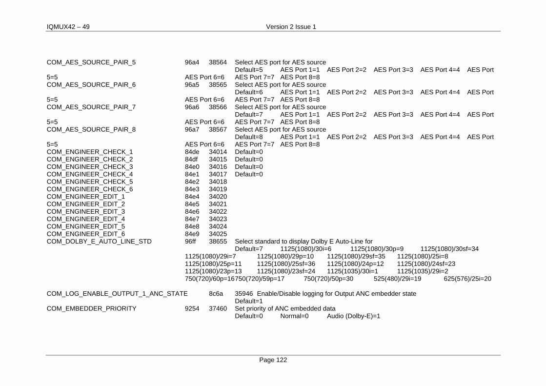
IQMUX42 – 49 Version 2 Issue 1
Page 122
COM_AES_SOURCE_PAIR_5 96a4 38564 Select AES port for AES source Default=5 AES Port 1=1 AES Port 2=2 AES Port 3=3 AES Port 4=4 AES Port 5=5 AES Port 6=6 AES Port 7=7 AES Port 8=8 COM_AES_SOURCE_PAIR_6 96a5 38565 Select AES port for AES source Default=6 AES Port 1=1 AES Port 2=2 AES Port 3=3 AES Port 4=4 AES Port 5=5 AES Port 6=6 AES Port 7=7 AES Port 8=8 COM_AES_SOURCE_PAIR_7 96a6 38566 Select AES port for AES source Default=7 AES Port 1=1 AES Port 2=2 AES Port 3=3 AES Port 4=4 AES Port 5=5 AES Port 6=6 AES Port 7=7 AES Port 8=8 COM_AES_SOURCE_PAIR_8 96a7 38567 Select AES port for AES source Default=8 AES Port 1=1 AES Port 2=2 AES Port 3=3 AES Port 4=4 AES Port 5=5 AES Port 6=6 AES Port 7=7 AES Port 8=8 COM_ENGINEER_CHECK_1 84de 34014 Default=0 COM_ENGINEER_CHECK_2 84df 34015 Default=0 COM_ENGINEER_CHECK_3 84e0 34016 Default=0 COM_ENGINEER_CHECK_4 84e1 34017 Default=0 COM_ENGINEER_CHECK_5 84e2 34018 COM_ENGINEER_CHECK_6 84e3 34019 COM_ENGINEER_EDIT_1 84e4 34020 COM_ENGINEER_EDIT_2 84e5 34021 COM_ENGINEER_EDIT_3 84e6 34022 COM_ENGINEER_EDIT_4 84e7 34023 COM_ENGINEER_EDIT_5 84e8 34024 COM_ENGINEER_EDIT_6 84e9 34025 COM_DOLBY_E_AUTO_LINE_STD 96ff 38655 Select standard to display Dolby E Auto-Line for Default=7 1125(1080)/30i=6 1125(1080)/30p=9 1125(1080)/30sf=34 1125(1080)/29i=7 1125(1080)/29p=10 1125(1080)/29sf=35 1125(1080)/25i=8 1125(1080)/25p=11 1125(1080)/25sf=36 1125(1080)/24p=12 1125(1080)/24sf=23 1125(1080)/23p=13 1125(1080)/23sf=24 1125(1035)/30i=1 1125(1035)/29i=2 750(720)/60p=16 750(720)/59p=17 750(720)/50p=30 525(480)/29i=19 625(576)/25i=20 COM_LOG_ENABLE_OUTPUT_1_ANC_STATE 8c6a 35946 Enable/Disable logging for Output ANC embedder state Default=1 COM_EMBEDDER_PRIORITY 9254 37460 Set priority of ANC embedded data Default=0 Normal=0 Audio (Dolby-E)=1
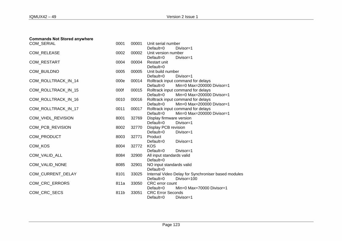
IQMUX42 – 49 Version 2 Issue 1
Page 123
Commands Not Stored anywhere COM_SERIAL 0001 00001 Unit serial number Default=0 Divisor=1 COM_RELEASE 0002 00002 Unit version number Default=0 Divisor=1 COM_RESTART 0004 00004 Restart unit Default=0 COM_BUILDNO 0005 00005 Unit build number Default=0 Divisor=1 COM_ROLLTRACK_IN_14 000e 00014 Rolltrack input command for delays Default=0 Min=0 Max=200000 Divisor=1 COM_ROLLTRACK_IN_15 000f 00015 Rolltrack input command for delays Default=0 Min=0 Max=200000 Divisor=1 COM_ROLLTRACK_IN_16 0010 00016 Rolltrack input command for delays Default=0 Min=0 Max=200000 Divisor=1 COM_ROLLTRACK_IN_17 0011 00017 Rolltrack input command for delays Default=0 Min=0 Max=200000 Divisor=1 COM_VHDL_REVISION 8001 32769 Display firmware version Default=0 Divisor=1 COM_PCB_REVISION 8002 32770 Display PCB revision Default=0 Divisor=1 COM_PRODUCT 8003 32771 Product Default=0 Divisor=1 COM_KOS 8004 32772 KOS Default=0 Divisor=1 COM_VALID_ALL 8084 32900 All input standards valid Default=0 COM_VALID_NONE 8085 32901 NO input standards valid Default=0 COM_CURRENT_DELAY 8101 33025 Internal Video Delay for Synchroniser based modules Default=0 Divisor=100 COM_CRC_ERRORS 811a 33050 CRC error count Default=0 Min=0 Max=70000 Divisor=1 COM_CRC_SECS 811b 33051 CRC Error Seconds Default=0 Divisor=1
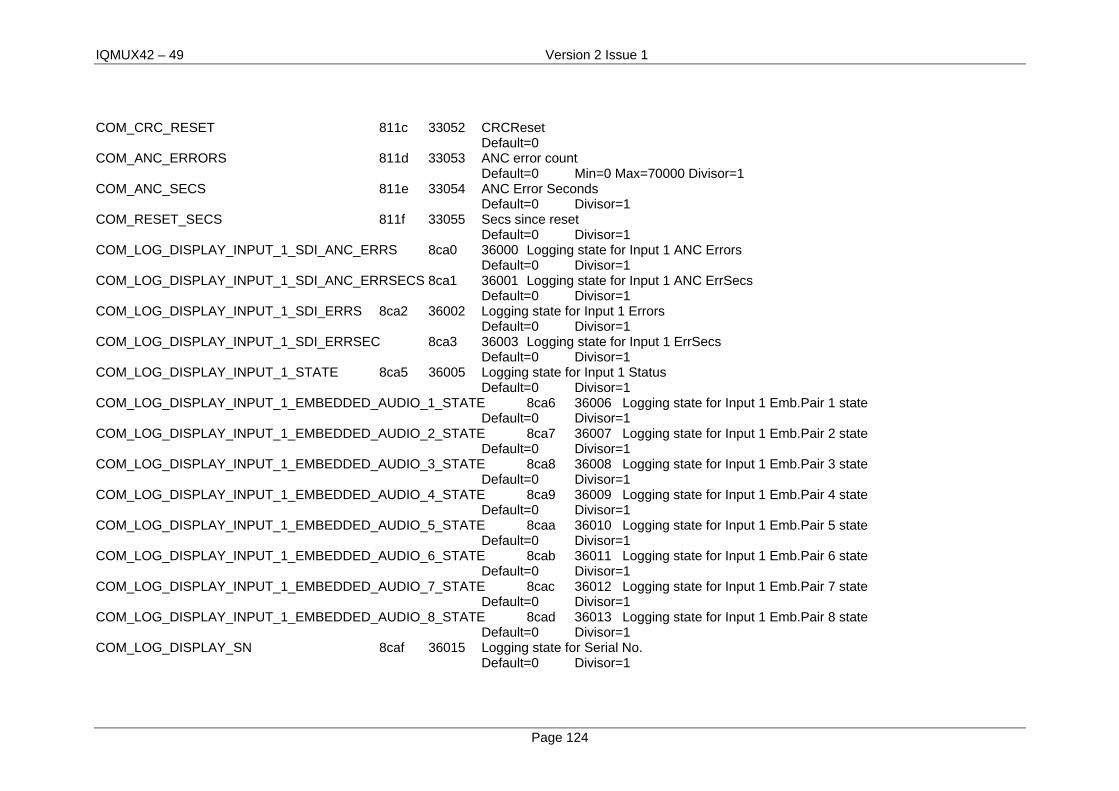
IQMUX42 – 49 Version 2 Issue 1
Page 124
COM_CRC_RESET 811c 33052 CRCReset Default=0 COM_ANC_ERRORS 811d 33053 ANC error count Default=0 Min=0 Max=70000 Divisor=1 COM_ANC_SECS 811e 33054 ANC Error Seconds Default=0 Divisor=1 COM_RESET_SECS 811f 33055 Secs since reset Default=0 Divisor=1 COM_LOG_DISPLAY_INPUT_1_SDI_ANC_ERRS 8ca0 36000 Logging state for Input 1 ANC Errors Default=0 Divisor=1 COM_LOG_DISPLAY_INPUT_1_SDI_ANC_ERRSECS 8ca1 36001 Logging state for Input 1 ANC ErrSecs Default=0 Divisor=1 COM_LOG_DISPLAY_INPUT_1_SDI_ERRS 8ca2 36002 Logging state for Input 1 Errors Default=0 Divisor=1 COM_LOG_DISPLAY_INPUT_1_SDI_ERRSEC 8ca3 36003 Logging state for Input 1 ErrSecs Default=0 Divisor=1 COM_LOG_DISPLAY_INPUT_1_STATE 8ca5 36005 Logging state for Input 1 Status Default=0 Divisor=1 COM_LOG_DISPLAY_INPUT_1_EMBEDDED_AUDIO_1_STATE 8ca6 36006 Logging state for Input 1 Emb.Pair 1 state Default=0 Divisor=1 COM_LOG_DISPLAY_INPUT_1_EMBEDDED_AUDIO_2_STATE 8ca7 36007 Logging state for Input 1 Emb.Pair 2 state Default=0 Divisor=1 COM_LOG_DISPLAY_INPUT_1_EMBEDDED_AUDIO_3_STATE 8ca8 36008 Logging state for Input 1 Emb.Pair 3 state Default=0 Divisor=1 COM_LOG_DISPLAY_INPUT_1_EMBEDDED_AUDIO_4_STATE 8ca9 36009 Logging state for Input 1 Emb.Pair 4 state Default=0 Divisor=1 COM_LOG_DISPLAY_INPUT_1_EMBEDDED_AUDIO_5_STATE 8caa 36010 Logging state for Input 1 Emb.Pair 5 state Default=0 Divisor=1 COM_LOG_DISPLAY_INPUT_1_EMBEDDED_AUDIO_6_STATE 8cab 36011 Logging state for Input 1 Emb.Pair 6 state Default=0 Divisor=1 COM_LOG_DISPLAY_INPUT_1_EMBEDDED_AUDIO_7_STATE 8cac 36012 Logging state for Input 1 Emb.Pair 7 state Default=0 Divisor=1 COM_LOG_DISPLAY_INPUT_1_EMBEDDED_AUDIO_8_STATE 8cad 36013 Logging state for Input 1 Emb.Pair 8 state Default=0 Divisor=1 COM_LOG_DISPLAY_SN 8caf 36015 Logging state for Serial No. Default=0 Divisor=1
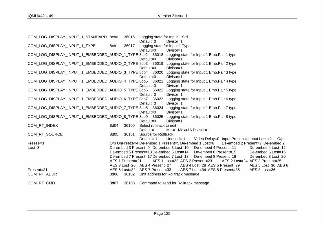
IQMUX42 – 49 Version 2 Issue 1
Page 125
COM_LOG_DISPLAY_INPUT_1_STANDARD 8cb0 36016 Logging state for Input 1 Std. Default=0 Divisor=1 COM_LOG_DISPLAY_INPUT_1_TYPE 8cb1 36017 Logging state for Input 1 Type Default=0 Divisor=1 COM_LOG_DISPLAY_INPUT_1_EMBEDDED_AUDIO_1_TYPE 8cb2 36018 Logging state for Input 1 Emb.Pair 1 type Default=0 Divisor=1 COM_LOG_DISPLAY_INPUT_1_EMBEDDED_AUDIO_2_TYPE 8cb3 36019 Logging state for Input 1 Emb.Pair 2 type Default=0 Divisor=1 COM_LOG_DISPLAY_INPUT_1_EMBEDDED_AUDIO_3_TYPE 8cb4 36020 Logging state for Input 1 Emb.Pair 3 type Default=0 Divisor=1 COM_LOG_DISPLAY_INPUT_1_EMBEDDED_AUDIO_4_TYPE 8cb5 36021 Logging state for Input 1 Emb.Pair 4 type Default=0 Divisor=1 COM_LOG_DISPLAY_INPUT_1_EMBEDDED_AUDIO_5_TYPE 8cb6 36022 Logging state for Input 1 Emb.Pair 5 type Default=0 Divisor=1 COM_LOG_DISPLAY_INPUT_1_EMBEDDED_AUDIO_6_TYPE 8cb7 36023 Logging state for Input 1 Emb.Pair 6 type Default=0 Divisor=1 COM_LOG_DISPLAY_INPUT_1_EMBEDDED_AUDIO_7_TYPE 8cb8 36024 Logging state for Input 1 Emb.Pair 7 type Default=0 Divisor=1 COM_LOG_DISPLAY_INPUT_1_EMBEDDED_AUDIO_8_TYPE 8cb9 36025 Logging state for Input 1 Emb.Pair 8 type Default=0 Divisor=1 COM_RT_INDEX 8d04 36100 Select rolltrack to edit Default=1 Min=1 Max=16 Divisor=1 COM_RT_SOURCE 8d05 36101 Source for Rolltrack Default=-1 Unused=-1 Video Delay=0 Input Present=1 Input Loss=2 O/p Freeze=3 O/p UnFreeze=4 De-embed 1 Present=5 De-embed 1 Lost=6 De-embed 2 Present=7 De-embed 2 Lost=8 De-embed 3 Present=9 De-embed 3 Lost=10 De-embed 4 Present=11 De-embed 4 Lost=12 De-embed 5 Present=13 De-embed 5 Lost=14 De-embed 6 Present=15 De-embed 6 Lost=16 De-embed 7 Present=17 De-embed 7 Lost=18 De-embed 8 Present=19 De-embed 8 Lost=20 AES 1 Present=21 AES 1 Lost=22 AES 2 Present=23 AES 2 Lost=24 AES 3 Present=25 AES 3 Lost=26 AES 4 Present=27 AES 4 Lost=28 AES 5 Present=29 AES 5 Lost=30 AES 6 Present=31 AES 6 Lost=32 AES 7 Present=33 AES 7 Lost=34 AES 8 Present=35 AES 8 Lost=36 COM_RT_ADDR 8d06 36102 Unit address for Rolltrack message COM_RT_CMD 8d07 36103 Command to send for Rolltrack message
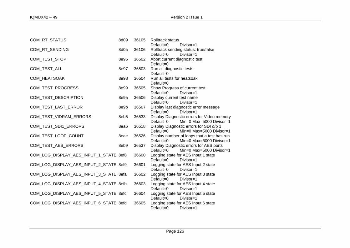
IQMUX42 – 49 Version 2 Issue 1
Page 126
COM_RT_STATUS 8d09 36105 Rolltrack status Default=0 Divisor=1 COM_RT_SENDING 8d0a 36106 Rolltrack sending status: true/false Default=0 Divisor=1 COM_TEST_STOP 8e96 36502 Abort current diagnostic test Default=0 COM_TEST_ALL 8e97 36503 Run all diagnostic tests Default=0 COM_HEATSOAK 8e98 36504 Run all tests for heatsoak Default=0 COM_TEST_PROGRESS 8e99 36505 Show Progress of current test Default=0 Divisor=1 COM_TEST_DESCRIPTION 8e9a 36506 Display current test name Default=0 Divisor=1 COM_TEST_LAST_ERROR 8e9b 36507 Display last diagnostic error message Default=0 Divisor=1 COM_TEST_VIDRAM_ERRORS 8eb5 36533 Display Diagnostic errors for Video memory Default=0 Min=0 Max=5000 Divisor=1 COM_TEST_SDI1_ERRORS 8ea6 36518 Display Diagnostic errors for SDI o/p 1 Default=0 Min=0 Max=5000 Divisor=1 COM_TEST_LOOP_COUNT 8eae 36526 Display number of loops that a test has run Default=0 Min=0 Max=5000 Divisor=1 COM_TEST_AES_ERRORS 8eb9 36537 Display Diagnostic errors for AES ports Default=0 Min=0 Max=5000 Divisor=1 COM_LOG_DISPLAY_AES_INPUT_1_STATE 8ef8 36600 Logging state for AES Input 1 state Default=0 Divisor=1 COM_LOG_DISPLAY_AES_INPUT_2_STATE 8ef9 36601 Logging state for AES Input 2 state Default=0 Divisor=1 COM_LOG_DISPLAY_AES_INPUT_3_STATE 8efa 36602 Logging state for AES Input 3 state Default=0 Divisor=1 COM_LOG_DISPLAY_AES_INPUT_4_STATE 8efb 36603 Logging state for AES Input 4 state Default=0 Divisor=1 COM_LOG_DISPLAY_AES_INPUT_5_STATE 8efc 36604 Logging state for AES Input 5 state Default=0 Divisor=1 COM_LOG_DISPLAY_AES_INPUT_6_STATE 8efd 36605 Logging state for AES Input 6 state Default=0 Divisor=1
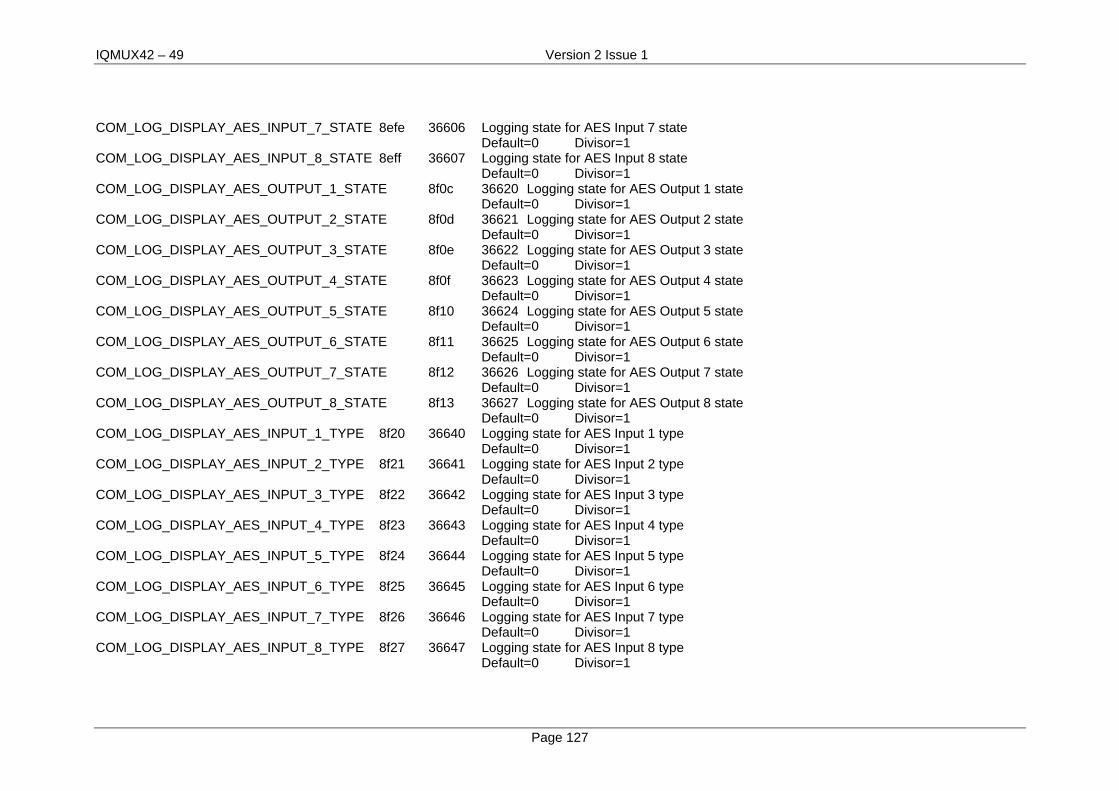
IQMUX42 – 49 Version 2 Issue 1
Page 127
COM_LOG_DISPLAY_AES_INPUT_7_STATE 8efe 36606 Logging state for AES Input 7 state Default=0 Divisor=1 COM_LOG_DISPLAY_AES_INPUT_8_STATE 8eff 36607 Logging state for AES Input 8 state Default=0 Divisor=1 COM_LOG_DISPLAY_AES_OUTPUT_1_STATE 8f0c 36620 Logging state for AES Output 1 state Default=0 Divisor=1 COM_LOG_DISPLAY_AES_OUTPUT_2_STATE 8f0d 36621 Logging state for AES Output 2 state Default=0 Divisor=1 COM_LOG_DISPLAY_AES_OUTPUT_3_STATE 8f0e 36622 Logging state for AES Output 3 state Default=0 Divisor=1 COM_LOG_DISPLAY_AES_OUTPUT_4_STATE 8f0f 36623 Logging state for AES Output 4 state Default=0 Divisor=1 COM_LOG_DISPLAY_AES_OUTPUT_5_STATE 8f10 36624 Logging state for AES Output 5 state Default=0 Divisor=1 COM_LOG_DISPLAY_AES_OUTPUT_6_STATE 8f11 36625 Logging state for AES Output 6 state Default=0 Divisor=1 COM_LOG_DISPLAY_AES_OUTPUT_7_STATE 8f12 36626 Logging state for AES Output 7 state Default=0 Divisor=1 COM_LOG_DISPLAY_AES_OUTPUT_8_STATE 8f13 36627 Logging state for AES Output 8 state Default=0 Divisor=1 COM_LOG_DISPLAY_AES_INPUT_1_TYPE 8f20 36640 Logging state for AES Input 1 type Default=0 Divisor=1 COM_LOG_DISPLAY_AES_INPUT_2_TYPE 8f21 36641 Logging state for AES Input 2 type Default=0 Divisor=1 COM_LOG_DISPLAY_AES_INPUT_3_TYPE 8f22 36642 Logging state for AES Input 3 type Default=0 Divisor=1 COM_LOG_DISPLAY_AES_INPUT_4_TYPE 8f23 36643 Logging state for AES Input 4 type Default=0 Divisor=1 COM_LOG_DISPLAY_AES_INPUT_5_TYPE 8f24 36644 Logging state for AES Input 5 type Default=0 Divisor=1 COM_LOG_DISPLAY_AES_INPUT_6_TYPE 8f25 36645 Logging state for AES Input 6 type Default=0 Divisor=1 COM_LOG_DISPLAY_AES_INPUT_7_TYPE 8f26 36646 Logging state for AES Input 7 type Default=0 Divisor=1 COM_LOG_DISPLAY_AES_INPUT_8_TYPE 8f27 36647 Logging state for AES Input 8 type Default=0 Divisor=1
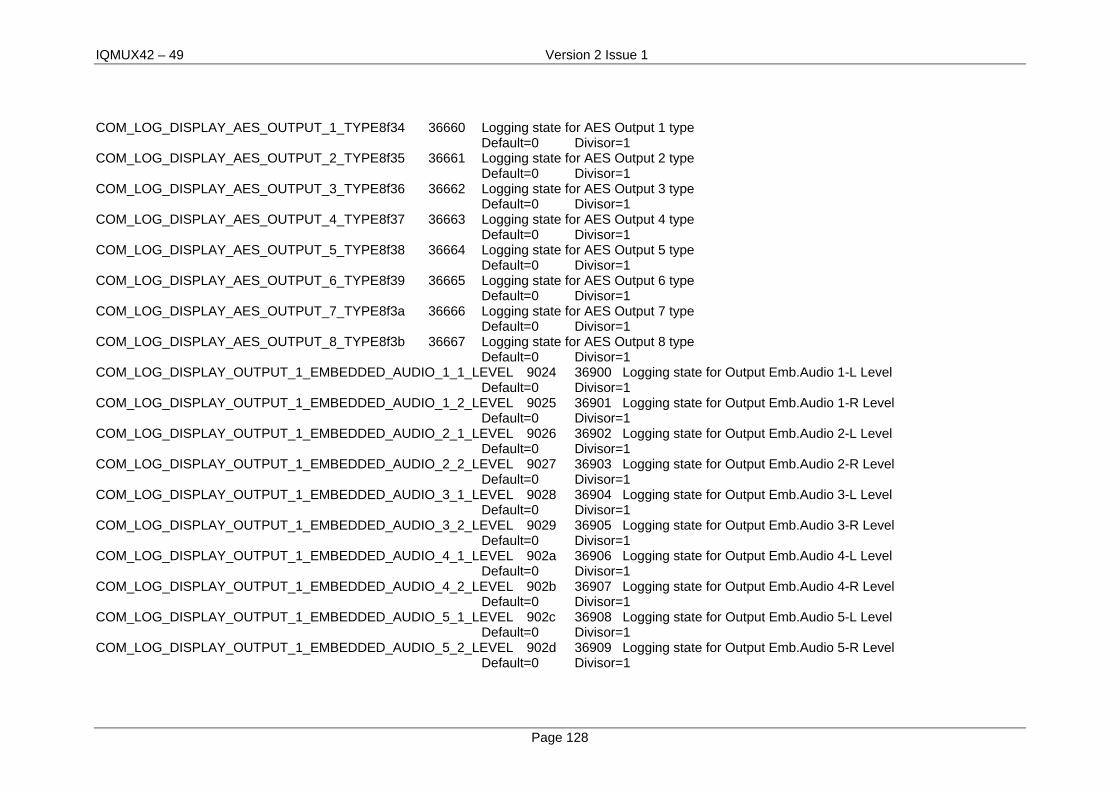
IQMUX42 – 49 Version 2 Issue 1
Page 128
COM_LOG_DISPLAY_AES_OUTPUT_1_TYPE 8f34 36660 Logging state for AES Output 1 type Default=0 Divisor=1 COM_LOG_DISPLAY_AES_OUTPUT_2_TYPE 8f35 36661 Logging state for AES Output 2 type Default=0 Divisor=1 COM_LOG_DISPLAY_AES_OUTPUT_3_TYPE 8f36 36662 Logging state for AES Output 3 type Default=0 Divisor=1 COM_LOG_DISPLAY_AES_OUTPUT_4_TYPE 8f37 36663 Logging state for AES Output 4 type Default=0 Divisor=1 COM_LOG_DISPLAY_AES_OUTPUT_5_TYPE 8f38 36664 Logging state for AES Output 5 type Default=0 Divisor=1 COM_LOG_DISPLAY_AES_OUTPUT_6_TYPE 8f39 36665 Logging state for AES Output 6 type Default=0 Divisor=1 COM_LOG_DISPLAY_AES_OUTPUT_7_TYPE 8f3a 36666 Logging state for AES Output 7 type Default=0 Divisor=1 COM_LOG_DISPLAY_AES_OUTPUT_8_TYPE 8f3b 36667 Logging state for AES Output 8 type Default=0 Divisor=1 COM_LOG_DISPLAY_OUTPUT_1_EMBEDDED_AUDIO_1_1_LEVEL 9024 36900 Logging state for Output Emb.Audio 1-L Level Default=0 Divisor=1 COM_LOG_DISPLAY_OUTPUT_1_EMBEDDED_AUDIO_1_2_LEVEL 9025 36901 Logging state for Output Emb.Audio 1-R Level Default=0 Divisor=1 COM_LOG_DISPLAY_OUTPUT_1_EMBEDDED_AUDIO_2_1_LEVEL 9026 36902 Logging state for Output Emb.Audio 2-L Level Default=0 Divisor=1 COM_LOG_DISPLAY_OUTPUT_1_EMBEDDED_AUDIO_2_2_LEVEL 9027 36903 Logging state for Output Emb.Audio 2-R Level Default=0 Divisor=1 COM_LOG_DISPLAY_OUTPUT_1_EMBEDDED_AUDIO_3_1_LEVEL 9028 36904 Logging state for Output Emb.Audio 3-L Level Default=0 Divisor=1 COM_LOG_DISPLAY_OUTPUT_1_EMBEDDED_AUDIO_3_2_LEVEL 9029 36905 Logging state for Output Emb.Audio 3-R Level Default=0 Divisor=1 COM_LOG_DISPLAY_OUTPUT_1_EMBEDDED_AUDIO_4_1_LEVEL 902a 36906 Logging state for Output Emb.Audio 4-L Level Default=0 Divisor=1 COM_LOG_DISPLAY_OUTPUT_1_EMBEDDED_AUDIO_4_2_LEVEL 902b 36907 Logging state for Output Emb.Audio 4-R Level Default=0 Divisor=1 COM_LOG_DISPLAY_OUTPUT_1_EMBEDDED_AUDIO_5_1_LEVEL 902c 36908 Logging state for Output Emb.Audio 5-L Level Default=0 Divisor=1 COM_LOG_DISPLAY_OUTPUT_1_EMBEDDED_AUDIO_5_2_LEVEL 902d 36909 Logging state for Output Emb.Audio 5-R Level Default=0 Divisor=1
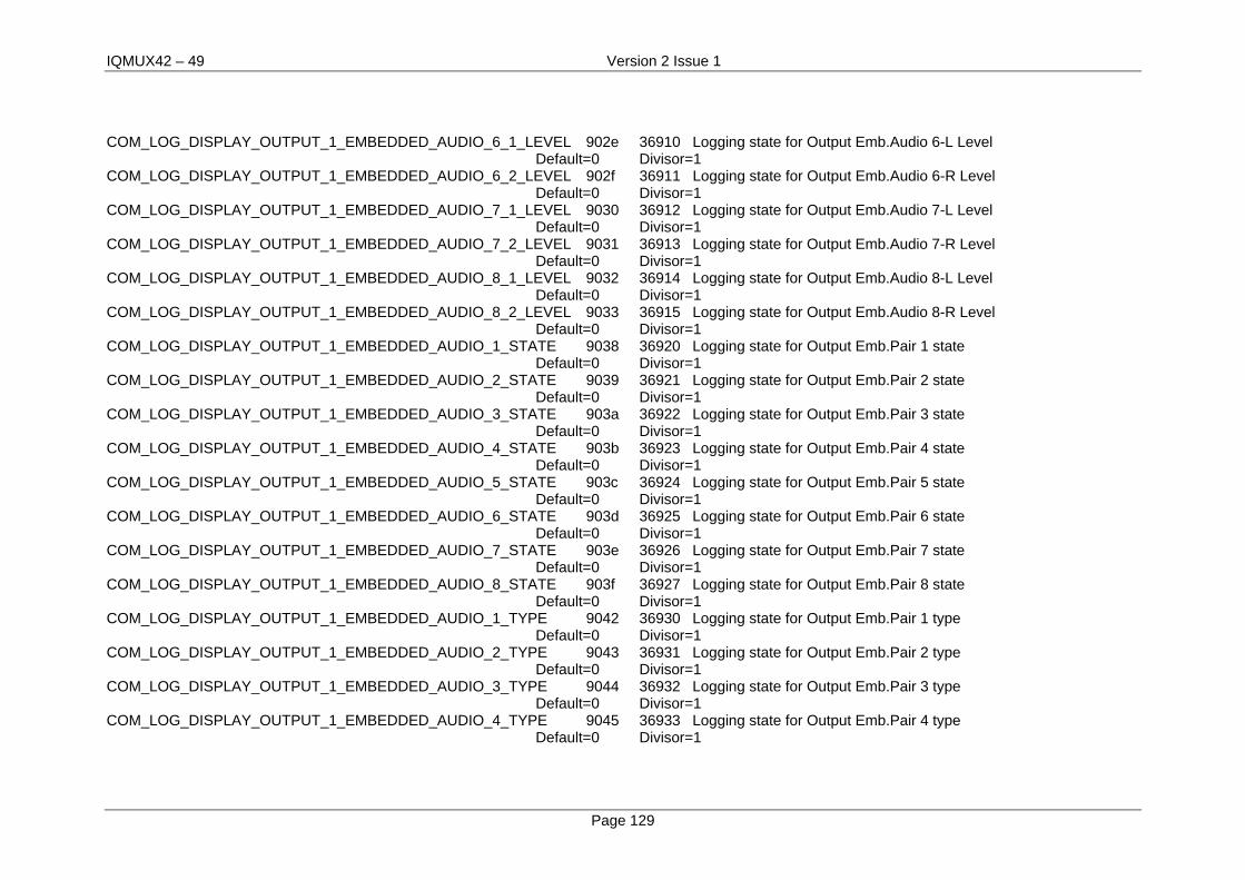
IQMUX42 – 49 Version 2 Issue 1
Page 129
COM_LOG_DISPLAY_OUTPUT_1_EMBEDDED_AUDIO_6_1_LEVEL 902e 36910 Logging state for Output Emb.Audio 6-L Level Default=0 Divisor=1 COM_LOG_DISPLAY_OUTPUT_1_EMBEDDED_AUDIO_6_2_LEVEL 902f 36911 Logging state for Output Emb.Audio 6-R Level Default=0 Divisor=1 COM_LOG_DISPLAY_OUTPUT_1_EMBEDDED_AUDIO_7_1_LEVEL 9030 36912 Logging state for Output Emb.Audio 7-L Level Default=0 Divisor=1 COM_LOG_DISPLAY_OUTPUT_1_EMBEDDED_AUDIO_7_2_LEVEL 9031 36913 Logging state for Output Emb.Audio 7-R Level Default=0 Divisor=1 COM_LOG_DISPLAY_OUTPUT_1_EMBEDDED_AUDIO_8_1_LEVEL 9032 36914 Logging state for Output Emb.Audio 8-L Level Default=0 Divisor=1 COM_LOG_DISPLAY_OUTPUT_1_EMBEDDED_AUDIO_8_2_LEVEL 9033 36915 Logging state for Output Emb.Audio 8-R Level Default=0 Divisor=1 COM_LOG_DISPLAY_OUTPUT_1_EMBEDDED_AUDIO_1_STATE 9038 36920 Logging state for Output Emb.Pair 1 state Default=0 Divisor=1 COM_LOG_DISPLAY_OUTPUT_1_EMBEDDED_AUDIO_2_STATE 9039 36921 Logging state for Output Emb.Pair 2 state Default=0 Divisor=1 COM_LOG_DISPLAY_OUTPUT_1_EMBEDDED_AUDIO_3_STATE 903a 36922 Logging state for Output Emb.Pair 3 state Default=0 Divisor=1 COM_LOG_DISPLAY_OUTPUT_1_EMBEDDED_AUDIO_4_STATE 903b 36923 Logging state for Output Emb.Pair 4 state Default=0 Divisor=1 COM_LOG_DISPLAY_OUTPUT_1_EMBEDDED_AUDIO_5_STATE 903c 36924 Logging state for Output Emb.Pair 5 state Default=0 Divisor=1 COM_LOG_DISPLAY_OUTPUT_1_EMBEDDED_AUDIO_6_STATE 903d 36925 Logging state for Output Emb.Pair 6 state Default=0 Divisor=1 COM_LOG_DISPLAY_OUTPUT_1_EMBEDDED_AUDIO_7_STATE 903e 36926 Logging state for Output Emb.Pair 7 state Default=0 Divisor=1 COM_LOG_DISPLAY_OUTPUT_1_EMBEDDED_AUDIO_8_STATE 903f 36927 Logging state for Output Emb.Pair 8 state Default=0 Divisor=1 COM_LOG_DISPLAY_OUTPUT_1_EMBEDDED_AUDIO_1_TYPE 9042 36930 Logging state for Output Emb.Pair 1 type Default=0 Divisor=1 COM_LOG_DISPLAY_OUTPUT_1_EMBEDDED_AUDIO_2_TYPE 9043 36931 Logging state for Output Emb.Pair 2 type Default=0 Divisor=1 COM_LOG_DISPLAY_OUTPUT_1_EMBEDDED_AUDIO_3_TYPE 9044 36932 Logging state for Output Emb.Pair 3 type Default=0 Divisor=1 COM_LOG_DISPLAY_OUTPUT_1_EMBEDDED_AUDIO_4_TYPE 9045 36933 Logging state for Output Emb.Pair 4 type Default=0 Divisor=1
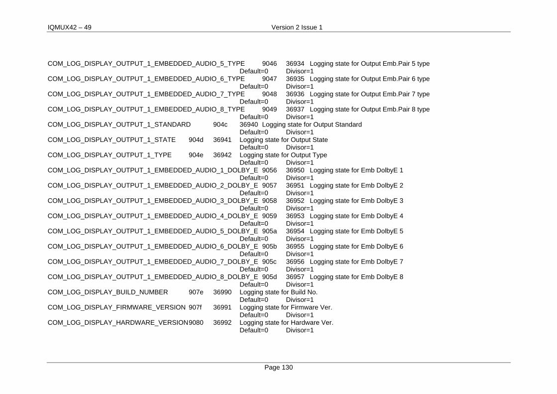
IQMUX42 – 49 Version 2 Issue 1
Page 130
COM_LOG_DISPLAY_OUTPUT_1_EMBEDDED_AUDIO_5_TYPE 9046 36934 Logging state for Output Emb.Pair 5 type Default=0 Divisor=1 COM_LOG_DISPLAY_OUTPUT_1_EMBEDDED_AUDIO_6_TYPE 9047 36935 Logging state for Output Emb.Pair 6 type Default=0 Divisor=1 COM_LOG_DISPLAY_OUTPUT_1_EMBEDDED_AUDIO_7_TYPE 9048 36936 Logging state for Output Emb.Pair 7 type Default=0 Divisor=1 COM_LOG_DISPLAY_OUTPUT_1_EMBEDDED_AUDIO_8_TYPE 9049 36937 Logging state for Output Emb.Pair 8 type Default=0 Divisor=1 COM_LOG_DISPLAY_OUTPUT_1_STANDARD 904c 36940 Logging state for Output Standard Default=0 Divisor=1 COM_LOG_DISPLAY_OUTPUT_1_STATE 904d 36941 Logging state for Output State Default=0 Divisor=1 COM_LOG_DISPLAY_OUTPUT_1_TYPE 904e 36942 Logging state for Output Type Default=0 Divisor=1 COM_LOG_DISPLAY_OUTPUT_1_EMBEDDED_AUDIO_1_DOLBY_E 9056 36950 Logging state for Emb DolbyE 1 Default=0 Divisor=1 COM_LOG_DISPLAY_OUTPUT_1_EMBEDDED_AUDIO_2_DOLBY_E 9057 36951 Logging state for Emb DolbyE 2 Default=0 Divisor=1 COM_LOG_DISPLAY_OUTPUT_1_EMBEDDED_AUDIO_3_DOLBY_E 9058 36952 Logging state for Emb DolbyE 3 Default=0 Divisor=1 COM_LOG_DISPLAY_OUTPUT_1_EMBEDDED_AUDIO_4_DOLBY_E 9059 36953 Logging state for Emb DolbyE 4 Default=0 Divisor=1 COM_LOG_DISPLAY_OUTPUT_1_EMBEDDED_AUDIO_5_DOLBY_E 905a 36954 Logging state for Emb DolbyE 5 Default=0 Divisor=1 COM_LOG_DISPLAY_OUTPUT_1_EMBEDDED_AUDIO_6_DOLBY_E 905b 36955 Logging state for Emb DolbyE 6 Default=0 Divisor=1 COM_LOG_DISPLAY_OUTPUT_1_EMBEDDED_AUDIO_7_DOLBY_E 905c 36956 Logging state for Emb DolbyE 7 Default=0 Divisor=1 COM_LOG_DISPLAY_OUTPUT_1_EMBEDDED_AUDIO_8_DOLBY_E 905d 36957 Logging state for Emb DolbyE 8 Default=0 Divisor=1 COM_LOG_DISPLAY_BUILD_NUMBER 907e 36990 Logging state for Build No. Default=0 Divisor=1 COM_LOG_DISPLAY_FIRMWARE_VERSION 907f 36991 Logging state for Firmware Ver. Default=0 Divisor=1 COM_LOG_DISPLAY_HARDWARE_VERSION 9080 36992 Logging state for Hardware Ver. Default=0 Divisor=1
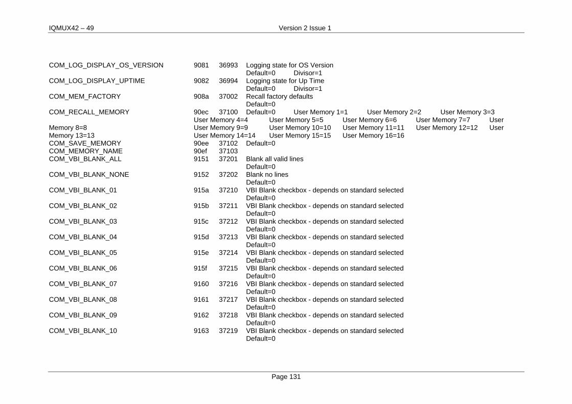
IQMUX42 – 49 Version 2 Issue 1
Page 131
COM_LOG_DISPLAY_OS_VERSION 9081 36993 Logging state for OS Version Default=0 Divisor=1 COM_LOG_DISPLAY_UPTIME 9082 36994 Logging state for Up Time Default=0 Divisor=1 COM_MEM_FACTORY 908a 37002 Recall factory defaults Default=0 COM_RECALL_MEMORY 90ec 37100 Default=0 User Memory 1=1 User Memory 2=2 User Memory 3=3 User Memory 4=4 User Memory 5=5 User Memory 6=6 User Memory 7=7 User Memory 8=8 User Memory 9=9 User Memory 10=10 User Memory 11=11 User Memory 12=12 User Memory 13=13 User Memory 14=14 User Memory 15=15 User Memory 16=16 COM_SAVE_MEMORY 90ee 37102 Default=0 COM_MEMORY_NAME 90ef 37103 COM_VBI_BLANK_ALL 9151 37201 Blank all valid lines Default=0 COM_VBI_BLANK_NONE 9152 37202 Blank no lines Default=0 COM_VBI_BLANK_01 915a 37210 VBI Blank checkbox - depends on standard selected Default=0 COM_VBI_BLANK_02 915b 37211 VBI Blank checkbox - depends on standard selected Default=0 COM_VBI_BLANK_03 915c 37212 VBI Blank checkbox - depends on standard selected Default=0 COM_VBI_BLANK_04 915d 37213 VBI Blank checkbox - depends on standard selected Default=0 COM_VBI_BLANK_05 915e 37214 VBI Blank checkbox - depends on standard selected Default=0 COM_VBI_BLANK_06 915f 37215 VBI Blank checkbox - depends on standard selected Default=0 COM_VBI_BLANK_07 9160 37216 VBI Blank checkbox - depends on standard selected Default=0 COM_VBI_BLANK_08 9161 37217 VBI Blank checkbox - depends on standard selected Default=0 COM_VBI_BLANK_09 9162 37218 VBI Blank checkbox - depends on standard selected Default=0 COM_VBI_BLANK_10 9163 37219 VBI Blank checkbox - depends on standard selected Default=0
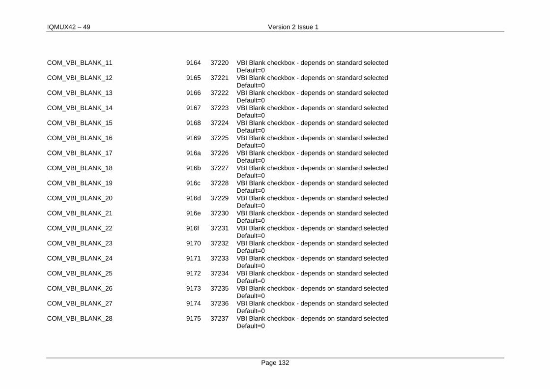
IQMUX42 – 49 Version 2 Issue 1
Page 132
COM_VBI_BLANK_11 9164 37220 VBI Blank checkbox - depends on standard selected Default=0 COM_VBI_BLANK_12 9165 37221 VBI Blank checkbox - depends on standard selected Default=0 COM_VBI_BLANK_13 9166 37222 VBI Blank checkbox - depends on standard selected Default=0 COM_VBI_BLANK_14 9167 37223 VBI Blank checkbox - depends on standard selected Default=0 COM_VBI_BLANK_15 9168 37224 VBI Blank checkbox - depends on standard selected Default=0 COM_VBI_BLANK_16 9169 37225 VBI Blank checkbox - depends on standard selected Default=0 COM_VBI_BLANK_17 916a 37226 VBI Blank checkbox - depends on standard selected Default=0 COM_VBI_BLANK_18 916b 37227 VBI Blank checkbox - depends on standard selected Default=0 COM_VBI_BLANK_19 916c 37228 VBI Blank checkbox - depends on standard selected Default=0 COM_VBI_BLANK_20 916d 37229 VBI Blank checkbox - depends on standard selected Default=0 COM_VBI_BLANK_21 916e 37230 VBI Blank checkbox - depends on standard selected Default=0 COM_VBI_BLANK_22 916f 37231 VBI Blank checkbox - depends on standard selected Default=0 COM_VBI_BLANK_23 9170 37232 VBI Blank checkbox - depends on standard selected Default=0 COM_VBI_BLANK_24 9171 37233 VBI Blank checkbox - depends on standard selected Default=0 COM_VBI_BLANK_25 9172 37234 VBI Blank checkbox - depends on standard selected Default=0 COM_VBI_BLANK_26 9173 37235 VBI Blank checkbox - depends on standard selected Default=0 COM_VBI_BLANK_27 9174 37236 VBI Blank checkbox - depends on standard selected Default=0 COM_VBI_BLANK_28 9175 37237 VBI Blank checkbox - depends on standard selected Default=0
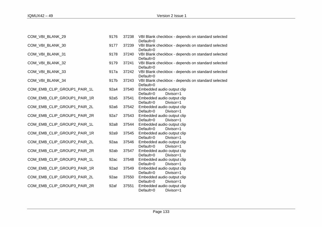
IQMUX42 – 49 Version 2 Issue 1
Page 133
COM_VBI_BLANK_29 9176 37238 VBI Blank checkbox - depends on standard selected Default=0 COM_VBI_BLANK_30 9177 37239 VBI Blank checkbox - depends on standard selected Default=0 COM_VBI_BLANK_31 9178 37240 VBI Blank checkbox - depends on standard selected Default=0 COM_VBI_BLANK_32 9179 37241 VBI Blank checkbox - depends on standard selected Default=0 COM_VBI_BLANK_33 917a 37242 VBI Blank checkbox - depends on standard selected Default=0 COM_VBI_BLANK_34 917b 37243 VBI Blank checkbox - depends on standard selected Default=0 COM_EMB_CLIP_GROUP1_PAIR_1L 92a4 37540 Embedded audio output clip Default=0 Divisor=1 COM_EMB_CLIP_GROUP1_PAIR_1R 92a5 37541 Embedded audio output clip Default=0 Divisor=1 COM_EMB_CLIP_GROUP1_PAIR_2L 92a6 37542 Embedded audio output clip Default=0 Divisor=1 COM_EMB_CLIP_GROUP1_PAIR_2R 92a7 37543 Embedded audio output clip Default=0 Divisor=1 COM_EMB_CLIP_GROUP2_PAIR_1L 92a8 37544 Embedded audio output clip Default=0 Divisor=1 COM_EMB_CLIP_GROUP2_PAIR_1R 92a9 37545 Embedded audio output clip Default=0 Divisor=1 COM_EMB_CLIP_GROUP2_PAIR_2L 92aa 37546 Embedded audio output clip Default=0 Divisor=1 COM_EMB_CLIP_GROUP2_PAIR_2R 92ab 37547 Embedded audio output clip Default=0 Divisor=1 COM_EMB_CLIP_GROUP3_PAIR_1L 92ac 37548 Embedded audio output clip Default=0 Divisor=1 COM_EMB_CLIP_GROUP3_PAIR_1R 92ad 37549 Embedded audio output clip Default=0 Divisor=1 COM_EMB_CLIP_GROUP3_PAIR_2L 92ae 37550 Embedded audio output clip Default=0 Divisor=1 COM_EMB_CLIP_GROUP3_PAIR_2R 92af 37551 Embedded audio output clip Default=0 Divisor=1
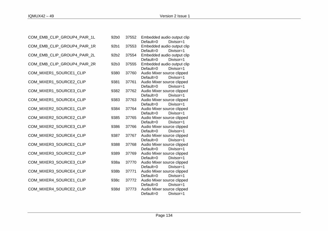
IQMUX42 – 49 Version 2 Issue 1
Page 134
COM_EMB_CLIP_GROUP4_PAIR_1L 92b0 37552 Embedded audio output clip Default=0 Divisor=1 COM_EMB_CLIP_GROUP4_PAIR_1R 92b1 37553 Embedded audio output clip Default=0 Divisor=1 COM_EMB_CLIP_GROUP4_PAIR_2L 92b2 37554 Embedded audio output clip Default=0 Divisor=1 COM_EMB_CLIP_GROUP4_PAIR_2R 92b3 37555 Embedded audio output clip Default=0 Divisor=1 COM_MIXER1_SOURCE1_CLIP 9380 37760 Audio Mixer source clipped Default=0 Divisor=1 COM_MIXER1_SOURCE2_CLIP 9381 37761 Audio Mixer source clipped Default=0 Divisor=1 COM_MIXER1_SOURCE3_CLIP 9382 37762 Audio Mixer source clipped Default=0 Divisor=1 COM_MIXER1_SOURCE4_CLIP 9383 37763 Audio Mixer source clipped Default=0 Divisor=1 COM_MIXER2_SOURCE1_CLIP 9384 37764 Audio Mixer source clipped Default=0 Divisor=1 COM_MIXER2_SOURCE2_CLIP 9385 37765 Audio Mixer source clipped Default=0 Divisor=1 COM_MIXER2_SOURCE3_CLIP 9386 37766 Audio Mixer source clipped Default=0 Divisor=1 COM_MIXER2_SOURCE4_CLIP 9387 37767 Audio Mixer source clipped Default=0 Divisor=1 COM_MIXER3_SOURCE1_CLIP 9388 37768 Audio Mixer source clipped Default=0 Divisor=1 COM_MIXER3_SOURCE2_CLIP 9389 37769 Audio Mixer source clipped Default=0 Divisor=1 COM_MIXER3_SOURCE3_CLIP 938a 37770 Audio Mixer source clipped Default=0 Divisor=1 COM_MIXER3_SOURCE4_CLIP 938b 37771 Audio Mixer source clipped Default=0 Divisor=1 COM_MIXER4_SOURCE1_CLIP 938c 37772 Audio Mixer source clipped Default=0 Divisor=1 COM_MIXER4_SOURCE2_CLIP 938d 37773 Audio Mixer source clipped Default=0 Divisor=1
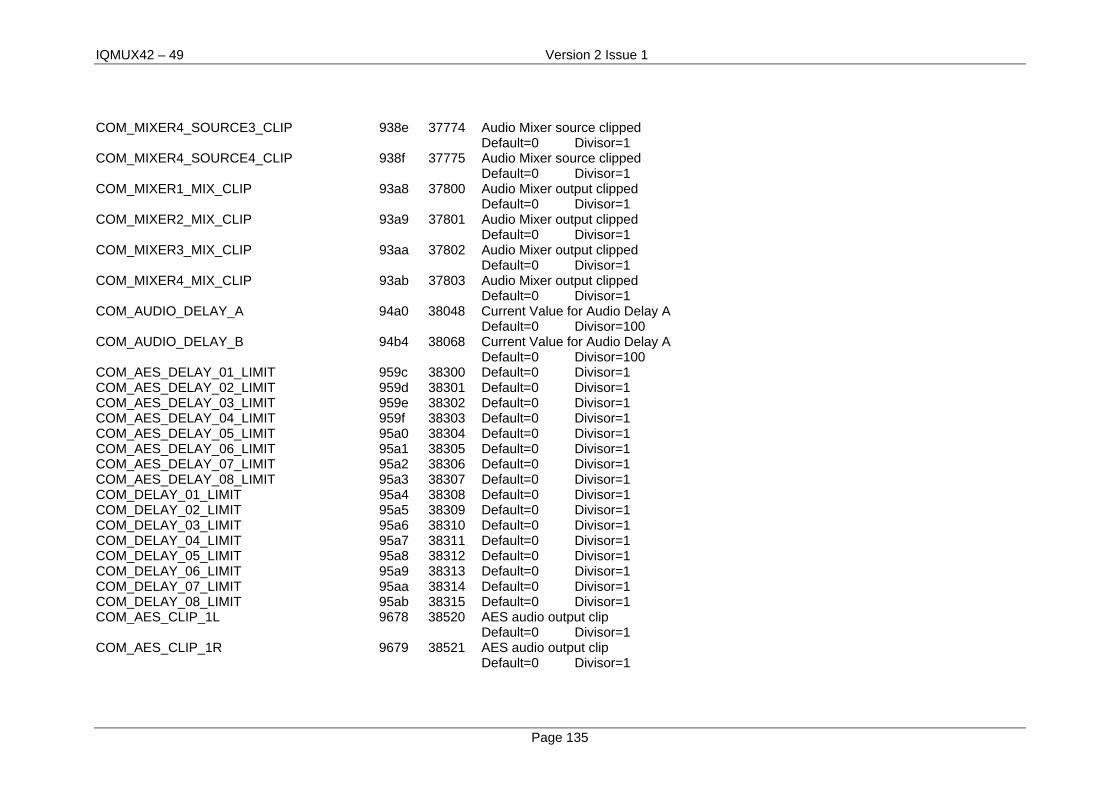
IQMUX42 – 49 Version 2 Issue 1
Page 135
COM_MIXER4_SOURCE3_CLIP 938e 37774 Audio Mixer source clipped Default=0 Divisor=1 COM_MIXER4_SOURCE4_CLIP 938f 37775 Audio Mixer source clipped Default=0 Divisor=1 COM_MIXER1_MIX_CLIP 93a8 37800 Audio Mixer output clipped Default=0 Divisor=1 COM_MIXER2_MIX_CLIP 93a9 37801 Audio Mixer output clipped Default=0 Divisor=1 COM_MIXER3_MIX_CLIP 93aa 37802 Audio Mixer output clipped Default=0 Divisor=1 COM_MIXER4_MIX_CLIP 93ab 37803 Audio Mixer output clipped Default=0 Divisor=1 COM_AUDIO_DELAY_A 94a0 38048 Current Value for Audio Delay A Default=0 Divisor=100 COM_AUDIO_DELAY_B 94b4 38068 Current Value for Audio Delay A Default=0 Divisor=100 COM_AES_DELAY_01_LIMIT 959c 38300 Default=0 Divisor=1 COM_AES_DELAY_02_LIMIT 959d 38301 Default=0 Divisor=1 COM_AES_DELAY_03_LIMIT 959e 38302 Default=0 Divisor=1 COM_AES_DELAY_04_LIMIT 959f 38303 Default=0 Divisor=1 COM_AES_DELAY_05_LIMIT 95a0 38304 Default=0 Divisor=1 COM_AES_DELAY_06_LIMIT 95a1 38305 Default=0 Divisor=1 COM_AES_DELAY_07_LIMIT 95a2 38306 Default=0 Divisor=1 COM_AES_DELAY_08_LIMIT 95a3 38307 Default=0 Divisor=1 COM_DELAY_01_LIMIT 95a4 38308 Default=0 Divisor=1 COM_DELAY_02_LIMIT 95a5 38309 Default=0 Divisor=1 COM_DELAY_03_LIMIT 95a6 38310 Default=0 Divisor=1 COM_DELAY_04_LIMIT 95a7 38311 Default=0 Divisor=1 COM_DELAY_05_LIMIT 95a8 38312 Default=0 Divisor=1 COM_DELAY_06_LIMIT 95a9 38313 Default=0 Divisor=1 COM_DELAY_07_LIMIT 95aa 38314 Default=0 Divisor=1 COM_DELAY_08_LIMIT 95ab 38315 Default=0 Divisor=1 COM_AES_CLIP_1L 9678 38520 AES audio output clip Default=0 Divisor=1 COM_AES_CLIP_1R 9679 38521 AES audio output clip Default=0 Divisor=1
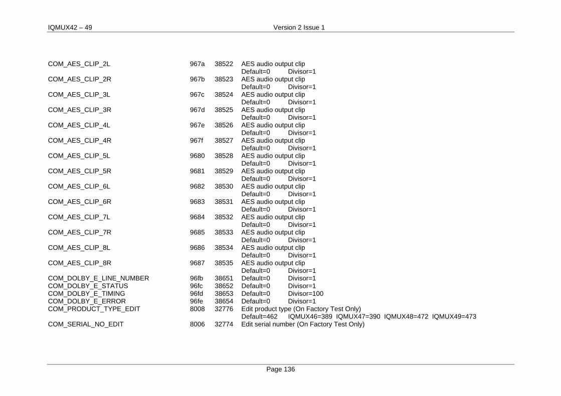
IQMUX42 – 49 Version 2 Issue 1
Page 136
COM_AES_CLIP_2L 967a 38522 AES audio output clip Default=0 Divisor=1 COM_AES_CLIP_2R 967b 38523 AES audio output clip Default=0 Divisor=1 COM_AES_CLIP_3L 967c 38524 AES audio output clip Default=0 Divisor=1 COM_AES_CLIP_3R 967d 38525 AES audio output clip Default=0 Divisor=1 COM_AES_CLIP_4L 967e 38526 AES audio output clip Default=0 Divisor=1 COM_AES_CLIP_4R 967f 38527 AES audio output clip Default=0 Divisor=1 COM_AES_CLIP_5L 9680 38528 AES audio output clip Default=0 Divisor=1 COM_AES_CLIP_5R 9681 38529 AES audio output clip Default=0 Divisor=1 COM_AES_CLIP_6L 9682 38530 AES audio output clip Default=0 Divisor=1 COM_AES_CLIP_6R 9683 38531 AES audio output clip Default=0 Divisor=1 COM_AES_CLIP_7L 9684 38532 AES audio output clip Default=0 Divisor=1 COM_AES_CLIP_7R 9685 38533 AES audio output clip Default=0 Divisor=1 COM_AES_CLIP_8L 9686 38534 AES audio output clip Default=0 Divisor=1 COM_AES_CLIP_8R 9687 38535 AES audio output clip Default=0 Divisor=1 COM_DOLBY_E_LINE_NUMBER 96fb 38651 Default=0 Divisor=1 COM_DOLBY_E_STATUS 96fc 38652 Default=0 Divisor=1 COM_DOLBY_E_TIMING 96fd 38653 Default=0 Divisor=100 COM_DOLBY_E_ERROR 96fe 38654 Default=0 Divisor=1 COM_PRODUCT_TYPE_EDIT 8008 32776 Edit product type (On Factory Test Only) Default=462 IQMUX46=389 IQMUX47=390 IQMUX48=472 IQMUX49=473 COM_SERIAL_NO_EDIT 8006 32774 Edit serial number (On Factory Test Only)
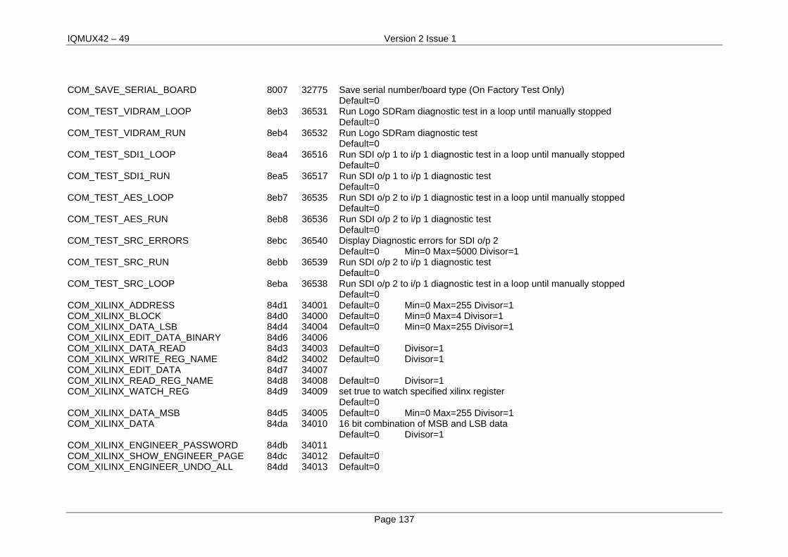
IQMUX42 – 49 Version 2 Issue 1
Page 137
COM_SAVE_SERIAL_BOARD 8007 32775 Save serial number/board type (On Factory Test Only) Default=0 COM_TEST_VIDRAM_LOOP 8eb3 36531 Run Logo SDRam diagnostic test in a loop until manually stopped Default=0 COM_TEST_VIDRAM_RUN 8eb4 36532 Run Logo SDRam diagnostic test Default=0 COM_TEST_SDI1_LOOP 8ea4 36516 Run SDI o/p 1 to i/p 1 diagnostic test in a loop until manually stopped Default=0 COM_TEST_SDI1_RUN 8ea5 36517 Run SDI o/p 1 to i/p 1 diagnostic test Default=0 COM_TEST_AES_LOOP 8eb7 36535 Run SDI o/p 2 to i/p 1 diagnostic test in a loop until manually stopped Default=0 COM_TEST_AES_RUN 8eb8 36536 Run SDI o/p 2 to i/p 1 diagnostic test Default=0 COM_TEST_SRC_ERRORS 8ebc 36540 Display Diagnostic errors for SDI o/p 2 Default=0 Min=0 Max=5000 Divisor=1 COM_TEST_SRC_RUN 8ebb 36539 Run SDI o/p 2 to i/p 1 diagnostic test Default=0 COM_TEST_SRC_LOOP 8eba 36538 Run SDI o/p 2 to i/p 1 diagnostic test in a loop until manually stopped Default=0 COM_XILINX_ADDRESS 84d1 34001 Default=0 Min=0 Max=255 Divisor=1 COM_XILINX_BLOCK 84d0 34000 Default=0 Min=0 Max=4 Divisor=1 COM_XILINX_DATA_LSB 84d4 34004 Default=0 Min=0 Max=255 Divisor=1 COM_XILINX_EDIT_DATA_BINARY 84d6 34006 COM_XILINX_DATA_READ 84d3 34003 Default=0 Divisor=1 COM_XILINX_WRITE_REG_NAME 84d2 34002 Default=0 Divisor=1 COM_XILINX_EDIT_DATA 84d7 34007 COM_XILINX_READ_REG_NAME 84d8 34008 Default=0 Divisor=1 COM_XILINX_WATCH_REG 84d9 34009 set true to watch specified xilinx register Default=0 COM_XILINX_DATA_MSB 84d5 34005 Default=0 Min=0 Max=255 Divisor=1 COM_XILINX_DATA 84da 34010 16 bit combination of MSB and LSB data Default=0 Divisor=1 COM_XILINX_ENGINEER_PASSWORD 84db 34011 COM_XILINX_SHOW_ENGINEER_PAGE 84dc 34012 Default=0 COM_XILINX_ENGINEER_UNDO_ALL 84dd 34013 Default=0
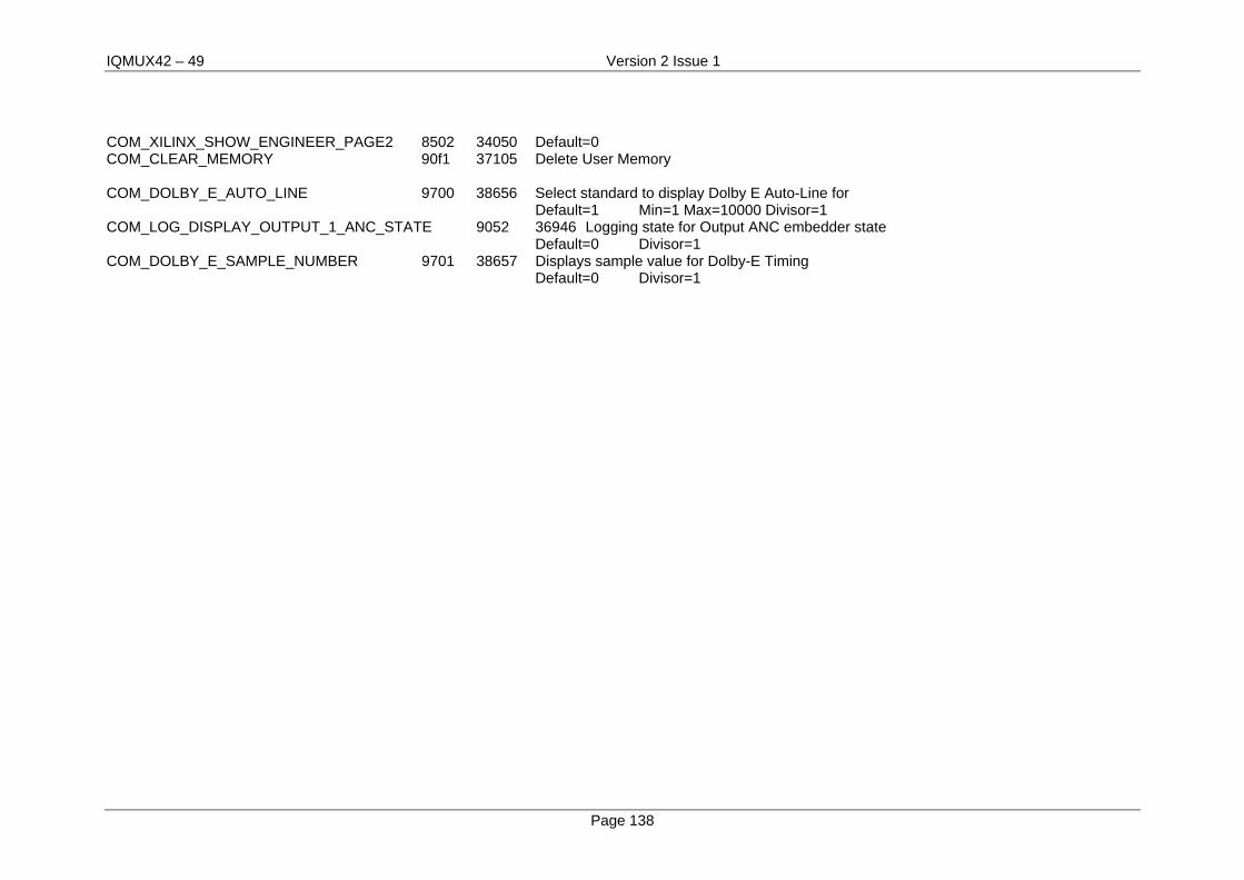
IQMUX42 – 49 Version 2 Issue 1
Page 138
COM_XILINX_SHOW_ENGINEER_PAGE2 8502 34050 Default=0 COM_CLEAR_MEMORY 90f1 37105 Delete User Memory COM_DOLBY_E_AUTO_LINE 9700 38656 Select standard to display Dolby E Auto-Line for Default=1 Min=1 Max=10000 Divisor=1 COM_LOG_DISPLAY_OUTPUT_1_ANC_STATE 9052 36946 Logging state for Output ANC embedder state Default=0 Divisor=1 COM_DOLBY_E_SAMPLE_NUMBER 9701 38657 Displays sample value for Dolby-E Timing Default=0 Divisor=1
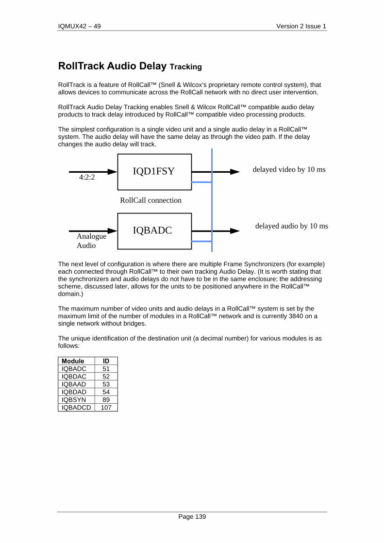
IQMUX42 – 49 Version 2 Issue 1
Page 139
RollTrack Audio Delay Tracking RollTrack is a feature of RollCall™ (Snell & Wilcox’s proprietary remote control system), that allows devices to communicate across the RollCall network with no direct user intervention. RollTrack Audio Delay Tracking enables Snell & Wilcox RollCall™ compatible audio delay products to track delay introduced by RollCall™ compatible video processing products. The simplest configuration is a single video unit and a single audio delay in a RollCall™ system. The audio delay will have the same delay as through the video path. If the delay changes the audio delay will track.
IQD1FSY
IQBADC
RollCall connection
4:2:2
AnalogueAudio
delayed video by 10 ms
delayed audio by 10 ms
The next level of configuration is where there are multiple Frame Synchronizers (for example) each connected through RollCall™ to their own tracking Audio Delay. (It is worth stating that the synchronizers and audio delays do not have to be in the same enclosure; the addressing scheme, discussed later, allows for the units to be positioned anywhere in the RollCall™ domain.) The maximum number of video units and audio delays in a RollCall™ system is set by the maximum limit of the number of modules in a RollCall™ network and is currently 3840 on a single network without bridges. The unique identification of the destination unit (a decimal number) for various modules is as follows: Module ID IQBADC 51 IQBDAC 52 IQBAAD 53 IQBDAD 54 IQBSYN 89 IQBADCD 107
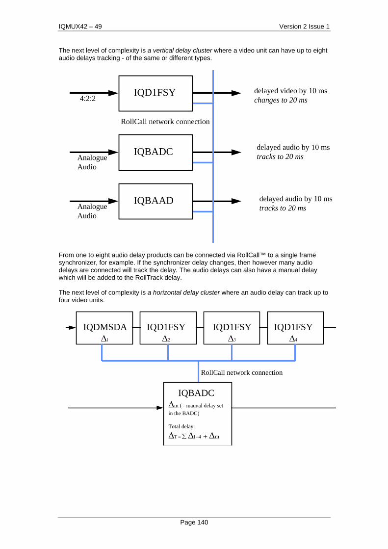
IQMUX42 – 49 Version 2 Issue 1
Page 140
The next level of complexity is a vertical delay cluster where a video unit can have up to eight audio delays tracking - of the same or different types.
IQD1FSY
IQBADC
IQBAAD
RollCall network connection
4:2:2
AnalogueAudio
AnalogueAudio
delayed video by 10 mschanges to 20 ms
delayed audio by 10 mstracks to 20 ms
delayed audio by 10 mstracks to 20 ms
From one to eight audio delay products can be connected via RollCall™ to a single frame synchronizer, for example. If the synchronizer delay changes, then however many audio delays are connected will track the delay. The audio delays can also have a manual delay which will be added to the RollTrack delay. The next level of complexity is a horizontal delay cluster where an audio delay can track up to four video units.
IQDMSDAΔ1
IQD1FSYΔ2
IQD1FSYΔ3
IQD1FSYΔ4
IQBADCΔm (= manual delay setin the BADC)
Total delay:
ΔΤ = ∑ Δ1−4 + Δm
RollCall network connection
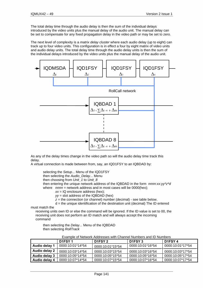
IQMUX42 – 49 Version 2 Issue 1
Page 141
The total delay time through the audio delay is then the sum of the individual delays introduced by the video units plus the manual delay of the audio unit. The manual delay can be set to compensate for any fixed propagation delay in the video path or may be set to zero. The next level of complexity is a matrix delay cluster where each audio delay (up to eight) can track up to four video units. This configuration is in effect a four by eight matrix of video units and audio delay units. The total delay time through the audio delay units is then the sum of the individual delays introduced by the video units plus the manual delay of the audio unit.
IQDMSDAΔ1
IQD1FSYΔ2
IQD1FSYΔ3
IQD1FSYΔ4
IQBDAD 1ΔΤ = ∑ Δ1−4 + Δm
RollCall networki
IQBDAD 8ΔΤ = ∑ Δ1−4 + Δm
As any of the delay times change in the video path so will the audio delay time track this delay. A virtual connection is made between from, say, an IQD1FSY to an IQBDAD by: selecting the Setup... Menu of the IQD1FSY then selecting the Audio_Delay... Menu then choosing from Unit_1 to Unit_8 then entering the unique network address of the IQBDAD in the form nnnn:xx:yy*z*d where nnnn = network address and in most cases will be 0000(hex); xx = IQ enclosure address (hex); yy = slot address of the IQBDAD (hex) z = the connection (or channel) number (decimal) - see table below. d = the unique identification of the destination unit (decimal) The ID entered must match the
receiving units own ID or else the command will be ignored. If the ID value is set to 00, the receiving unit does not perform an ID match and will always accept the incoming command
then selecting the Delay... Menu of the IQBDAD then selecting RollTrack Example of Network Addresses with Channel Numbers and ID Numbers D1FSY 1 D1FSY 2 D1FSY 3 D1FSY 4 Audio delay 1 0000:10:01*14*54 0000:10:01*15*54 0000:10:01*16*54 0000:10:01*17*54 Audio delay 2 0000:10:03*14*54 0000:10:03*15*54 0000:10:03*16*54 0000:10:03*17*54 Audio delay 3 0000:10:05*14*54 0000:10:05*15*54 0000:10:05*16*54 0000:10:05*17*54 Audio delay 4 0000:10:07*14*54 0000:10:07*15*54 0000:10:07*16*54 0000:10:07*17*54
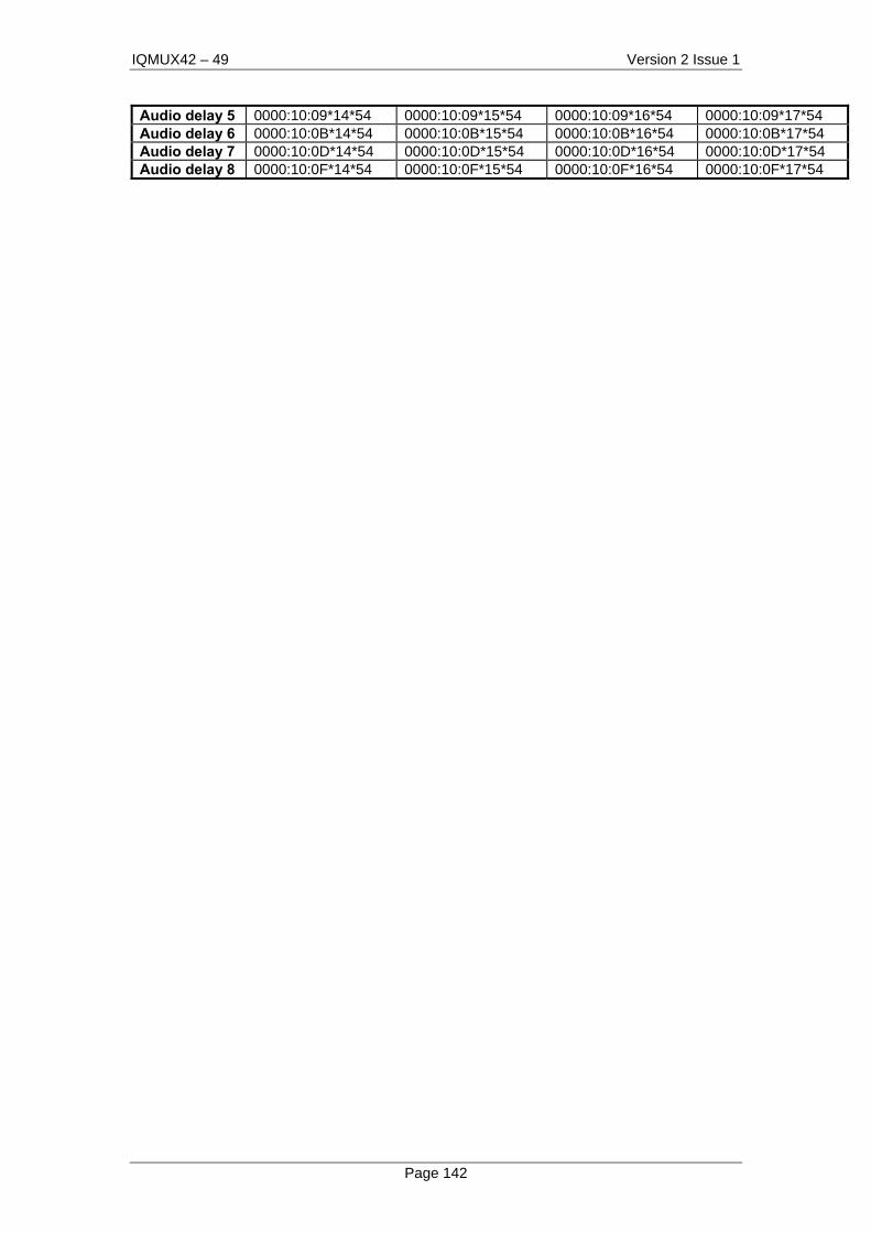
IQMUX42 – 49 Version 2 Issue 1
Page 142
Audio delay 5 0000:10:09*14*54 0000:10:09*15*54 0000:10:09*16*54 0000:10:09*17*54 Audio delay 6 0000:10:0B*14*54 0000:10:0B*15*54 0000:10:0B*16*54 0000:10:0B*17*54 Audio delay 7 0000:10:0D*14*54 0000:10:0D*15*54 0000:10:0D*16*54 0000:10:0D*17*54 Audio delay 8 0000:10:0F*14*54 0000:10:0F*15*54 0000:10:0F*16*54 0000:10:0F*17*54
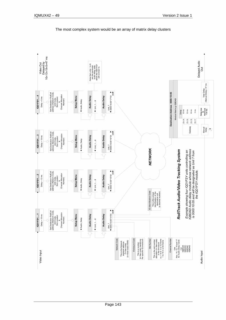
IQMUX42 – 49 Version 2 Issue 1
Page 143
The most complex system would be an array of matrix delay clusters
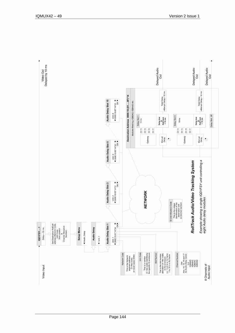
IQMUX42 – 49 Version 2 Issue 1
Page 144
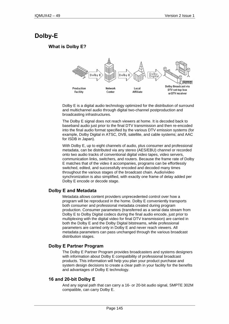
IQMUX42 – 49 Version 2 Issue 1
Page 145
Dolby-E What is Dolby E?
Dolby E is a digital audio technology optimized for the distribution of surround and multichannel audio through digital two-channel postproduction and broadcasting infrastructures.
The Dolby E signal does not reach viewers at home. It is decoded back to baseband audio just prior to the final DTV transmission and then re-encoded into the final audio format specified by the various DTV emission systems (for example, Dolby Digital in ATSC, DVB, satellite, and cable systems; and AAC for ISDB in Japan).
With Dolby E, up to eight channels of audio, plus consumer and professional metadata, can be distributed via any stereo (AES/EBU) channel or recorded onto two audio tracks of conventional digital video tapes, video servers, communication links, switchers, and routers. Because the frame rate of Dolby E matches that of the video it accompanies, programs can be effortlessly switched, edited, and successfully encoded and decoded many times throughout the various stages of the broadcast chain. Audio/video synchronization is also simplified, with exactly one frame of delay added per Dolby E encode or decode stage.
Dolby E and Metadata Metadata allows content providers unprecedented control over how a program will be reproduced in the home. Dolby E conveniently transports both consumer and professional metadata created during program production. Consumer parameters (transferred as a serial data stream from Dolby E to Dolby Digital codecs during the final audio encode, just prior to multiplexing with the digital video for final DTV transmission) are carried in both the Dolby E and the Dolby Digital bitstreams, while professional parameters are carried only in Dolby E and never reach viewers. All metadata parameters can pass unchanged through the various broadcast distribution stages.
Dolby E Partner Program The Dolby E Partner Program provides broadcasters and systems designers with information about Dolby E compatibility of professional broadcast products. This information will help you plan your product purchase and system design decisions to create a clear path in your facility for the benefits and advantages of Dolby E technology.
16 and 20-bit Dolby E And any signal path that can carry a 16- or 20-bit audio signal, SMPTE 302M compatible, can carry Dolby E.
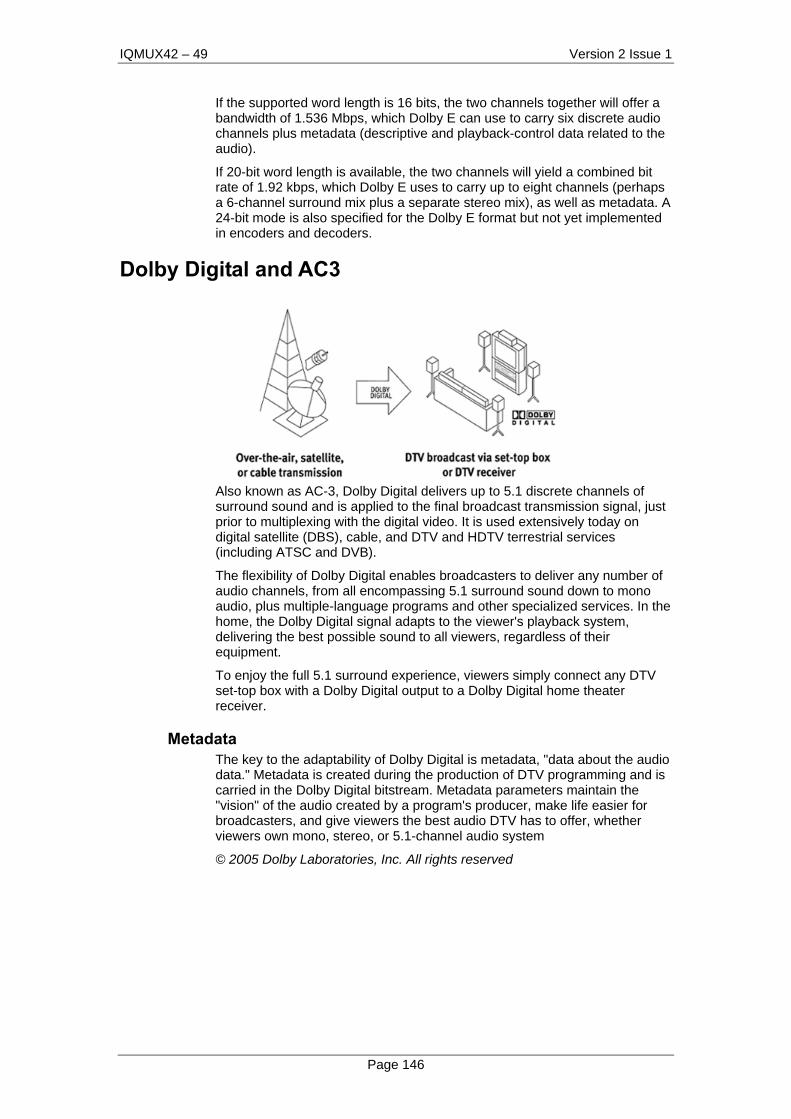
IQMUX42 – 49 Version 2 Issue 1
Page 146
If the supported word length is 16 bits, the two channels together will offer a bandwidth of 1.536 Mbps, which Dolby E can use to carry six discrete audio channels plus metadata (descriptive and playback-control data related to the audio).
If 20-bit word length is available, the two channels will yield a combined bit rate of 1.92 kbps, which Dolby E uses to carry up to eight channels (perhaps a 6-channel surround mix plus a separate stereo mix), as well as metadata. A 24-bit mode is also specified for the Dolby E format but not yet implemented in encoders and decoders.
Dolby Digital and AC3
Also known as AC-3, Dolby Digital delivers up to 5.1 discrete channels of surround sound and is applied to the final broadcast transmission signal, just prior to multiplexing with the digital video. It is used extensively today on digital satellite (DBS), cable, and DTV and HDTV terrestrial services (including ATSC and DVB).
The flexibility of Dolby Digital enables broadcasters to deliver any number of audio channels, from all encompassing 5.1 surround sound down to mono audio, plus multiple-language programs and other specialized services. In the home, the Dolby Digital signal adapts to the viewer's playback system, delivering the best possible sound to all viewers, regardless of their equipment.
To enjoy the full 5.1 surround experience, viewers simply connect any DTV set-top box with a Dolby Digital output to a Dolby Digital home theater receiver.
Metadata The key to the adaptability of Dolby Digital is metadata, "data about the audio data." Metadata is created during the production of DTV programming and is carried in the Dolby Digital bitstream. Metadata parameters maintain the "vision" of the audio created by a program's producer, make life easier for broadcasters, and give viewers the best audio DTV has to offer, whether viewers own mono, stereo, or 5.1-channel audio system
© 2005 Dolby Laboratories, Inc. All rights reserved
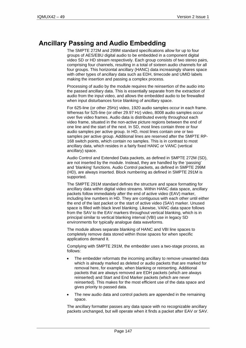
IQMUX42 – 49 Version 2 Issue 1
Page 147
Ancillary Passing and Audio Embedding The SMPTE 272M and 299M standard specifications allow for up to four groups of AES/EBU digital audio to be embedded in a component digital video SD or HD stream respectively. Each group consists of two stereo pairs, comprising four channels, resulting in a total of sixteen audio channels for all four groups. This horizontal ancillary (HANC) data increasingly shares space with other types of ancillary data such as EDH, timecode and UMID labels making the insertion and passing a complex process.
Processing of audio by the module requires the reinsertion of the audio into the passed ancillary data. This is essentially separate from the extraction of audio from the input video, and allows the embedded audio to be firewalled when input disturbances force blanking of ancillary space.
For 625-line (or other 25Hz) video, 1920 audio samples occur in each frame. Whereas for 525-line (or other 29.97 Hz) video, 8008 audio samples occur over five video frames. Audio data is distributed evenly throughout each video frame, situated in the non-active picture regions between the end of one line and the start of the next. In SD, most lines contain three or four audio samples per active group. In HD, most lines contain one or two samples per active group. Additional lines are reserved after the SMPTE RP-168 switch points, which contain no samples. This is in contrast to most ancillary data, which resides in a fairly fixed HANC or VANC (vertical ancillary) space.
Audio Control and Extended Data packets, as defined in SMPTE 272M (SD), are not inserted by the module. Instead, they are handled by the ‘passing’ and ‘blanking’ functions. Audio Control packets, as defined in SMPTE 299M (HD), are always inserted. Block numbering as defined in SMPTE 291M is supported.
The SMPTE 291M standard defines the structure and space formatting for ancillary data within digital video streams. Within HANC data space, ancillary packets follow immediately after the end of active video (EAV) marker, including line numbers in HD. They are contiguous with each other until either the end of the last packet or the start of active video (SAV) marker. Unused space is filled with black level blanking. Likewise, VANC data space follows from the SAV to the EAV markers throughout vertical blanking, which is in principal similar to vertical blanking interval (VBI) use in legacy SD environments for typically analogue data waveforms.
The module allows separate blanking of HANC and VBI line spaces to completely remove data stored within those spaces for when specific applications demand it.
Complying with SMPTE 291M, the embedder uses a two-stage process, as follows:
• The embedder reformats the incoming ancillary to remove unwanted data which is already marked as deleted or audio packets that are marked for removal here, for example, when blanking or reinserting. Additional packets that are always removed are EDH packets (which are always reinserted) and Start and End Marker packets (which are never reinserted). This makes for the most efficient use of the data space and gives priority to passed data.
• The new audio data and control packets are appended in the remaining space.
The ancillary formatter passes any data space with no recognizable ancillary packets unchanged, but will operate when it finds a packet after EAV or SAV.
IQMUX42 – 49 Version 2 Issue 1
Page 148
Data packets for passing are buffered while deleted packets are dropped. This requires a holding buffer and a delay so that all passed packets can be shuffled up earlier in the data space without gaps.
The following embed control section looks for the first free space after EAV. Once found, the embedding process is initiated with the first enabled group inserter. However, before starting the embedding for any of the inserter streams the remaining data space is checked to ensure that there is enough room for the ancillary packet. If not, the inserter is disabled to prevent corruption of the video format or generation of invalid ancillary data packets. This situation is a sample overflow which simply causes the data to be delayed until the following line. If this is repeated over many lines, there will be a full embed overflow, which is reported in the Audio Status window, on the card edge yellow Warning LED, and is logged.
Embedded ancillary data that does not conform to the space formatting requirements of SMPTE 291M may not be recognized, and so could be destroyed by the module. For example, if the data packets do not start immediately following the EAV marker the inserter will overwrite the packets. Similarly, if a data packet does start in the correct place but a second packet does not immediately follow the first one the second packet will be overwritten.
To summarize:
• Marked for Deletion and audio packets to be replaced, are removed from the ancillary data space for most efficient and clean use of data space.
• Ancillary packets are shuffled up within the data space during reformatting.
• Incoming ancillary data must be SMPTE 291M compliant.
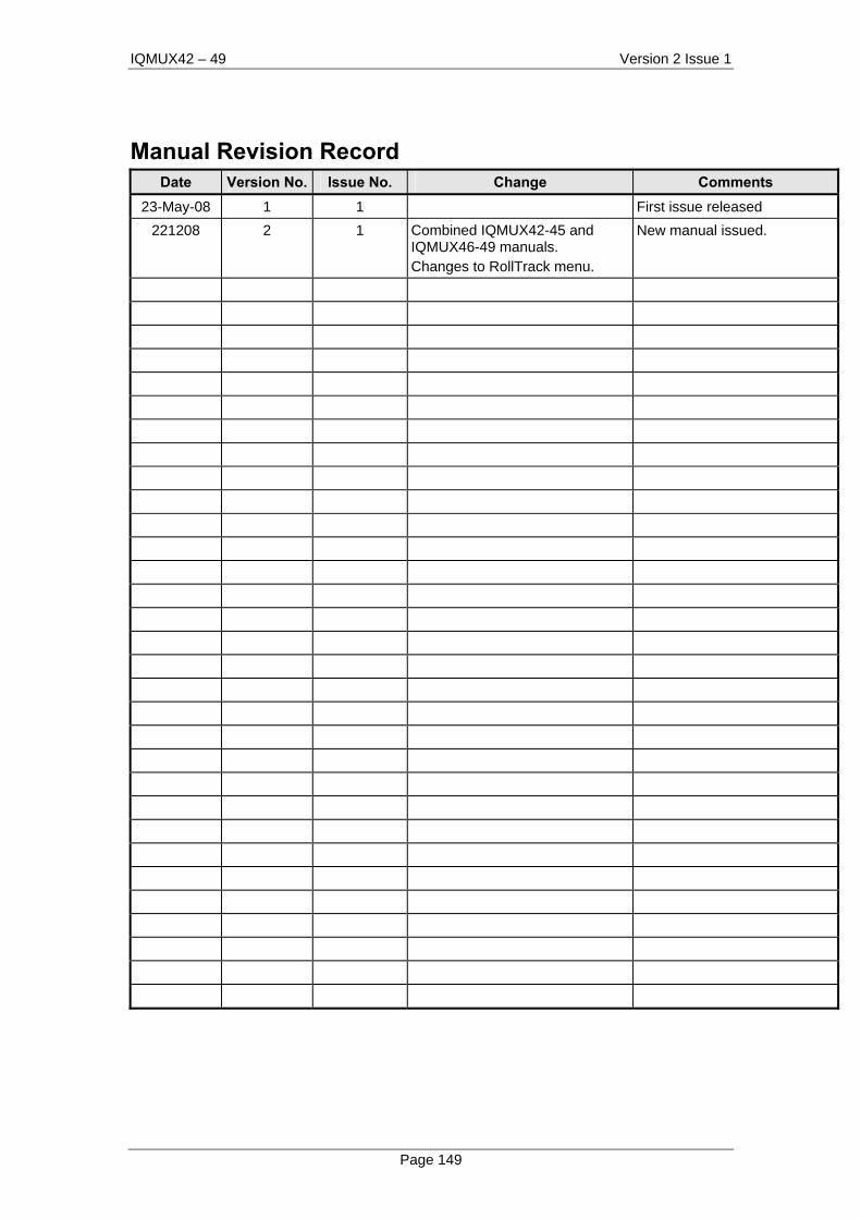
IQMUX42 – 49 Version 2 Issue 1
Page 149
Manual Revision Record Date Version No. Issue No. Change Comments
23-May-08 1 1 First issue released 221208 2 1 Combined IQMUX42-45 and
IQMUX46-49 manuals. Changes to RollTrack menu.
New manual issued.


![Hammerfall DSP System HDSP AES-32 - …1].pdfHammerfall® DSP System HDSP AES-32 ... 30.8 Connector Pinouts ... BO25MXLR4M4F3 Digital breakout cable AES/EBU, 9.9 ft (3 m)](https://img.pdfslide.us/doc/110x75/5afa5a047f8b9a2d5d8e29b2/hammerfall-dsp-system-hdsp-aes-32-1pdfhammerfall-dsp-system-hdsp-aes-32.jpg)