Embed Size (px)
Citation preview
IPS NASUIPS NASU
DYNAMICAL ANALYSIS AND ALLOWABLE VIBRATION DETERMINATION FOR THE PIPING
SYSTEMS.
DYNAMICAL ANALYSIS AND ALLOWABLE VIBRATION DETERMINATION FOR THE PIPING
SYSTEMS.
G.S. Pisarenko Institute for Problems of Strengthof National Academy of Science of Ukraine
Kiev, Ukraine
G.S. Pisarenko Institute for Problems of Strengthof National Academy of Science of Ukraine
Kiev, Ukraine
IPS NASUIPS NASUSoftware complex
«3D PipeMaster»Software complex
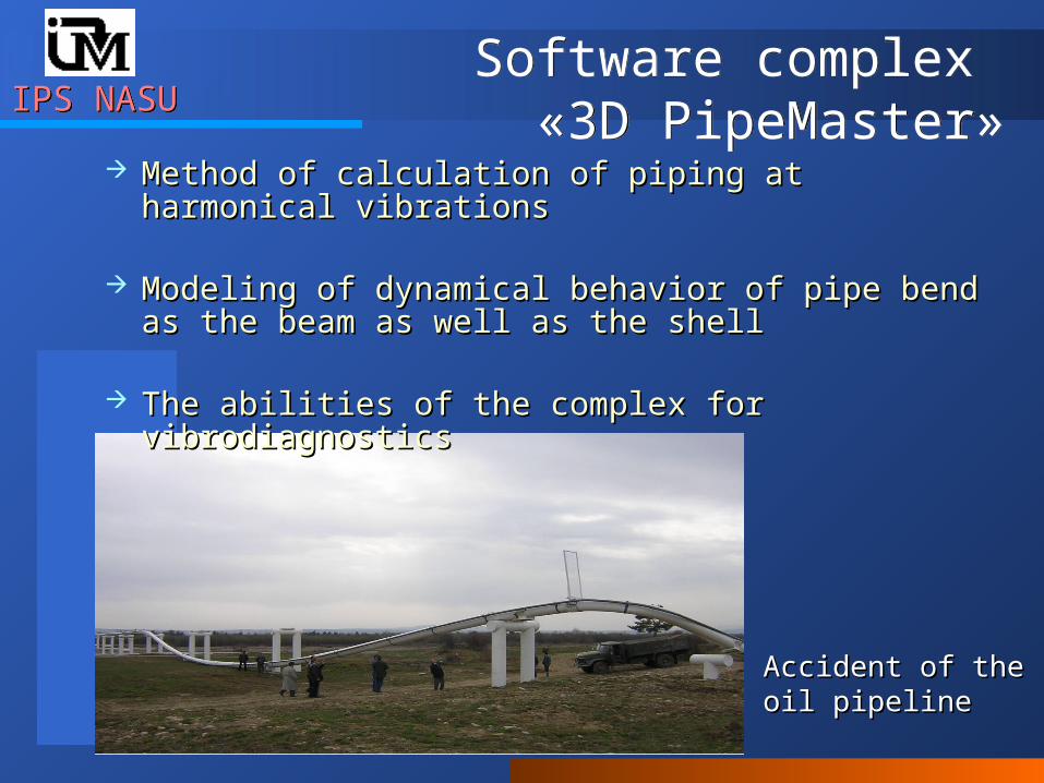
«3D PipeMaster» Method of calculation of piping at harmonical vibrationsMethod of calculation of piping at harmonical vibrations
Modeling of dynamical behavior of pipe bend as the Modeling of dynamical behavior of pipe bend as the beam as well as the shell beam as well as the shell
The abilities of the complex for vibrodiagnostics The abilities of the complex for vibrodiagnostics
Accident of the oil Accident of the oil pipeline pipeline
IPS NASUIPS NASU«3D PipeMaster»
Harmonical analysis«3D PipeMaster»
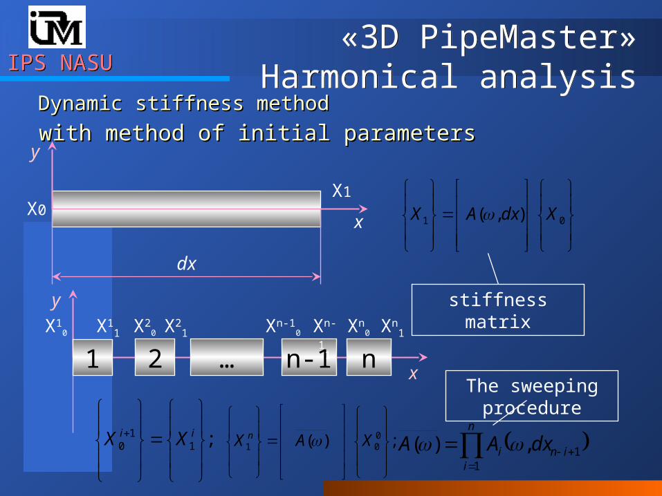
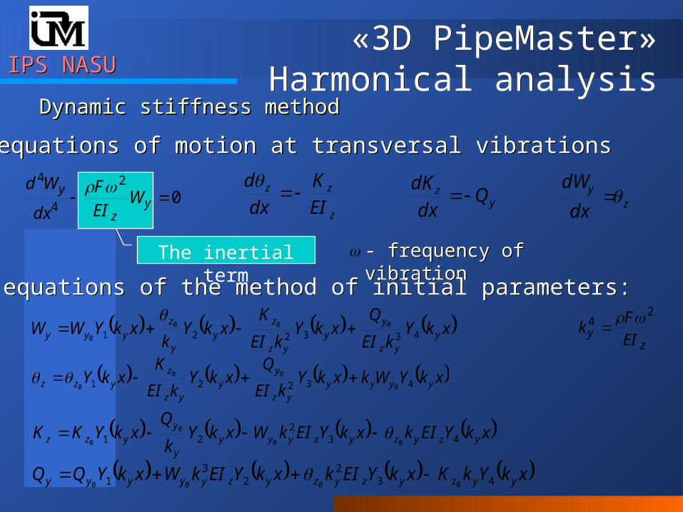
Harmonical analysisDynamic stiffness methodDynamic stiffness method
x
y
dx
X0X1
01 ),( XdxAX
stiffness matrixy
with method of initial parameterswith method of initial parameters
x
X10
2 … n-1 nX1
1 X20 X2
1 Xn-10 Xn
0Xn-11 Xn
1
1
;11
0
ii XX ;)( 0
01
XAX n
n
iini dxAA
11,)(
The sweeping procedure
IPS NASUIPS NASU
The inertial term
«3D PipeMaster» Harmonical analysis
«3D PipeMaster» Harmonical analysis
Dynamic stiffness methodDynamic stiffness method
02
4
4
yz
yW
EI
F
dx
Wd z
y
dx
dW
z
zz
EI
K
dx
d
y
z Qdx
dK
the equations of motion at transversal vibrations the equations of motion at transversal vibrations
- frequency of vibration- frequency of vibration
the equations of the method of initial parameters: the equations of the method of initial parameters:
xkYkEI
QxkY
kEI
KxkY
kxkYWW y
yz
y
yyz
z
yy
z
yyy 433221000
0
xkYWkxkYkEI
QxkY
kEI
KxkY yyyy
yz
yy
yz
zyzz 43221 0
00
0
xkYEIkxkYEIkWxkYk
QxkYKK yzyzyzyyy
y
yyzz 43
221 00
0
0
xkYkKxkYEIkxkYEIkWxkYQQ yyzyzyzyzyyyyy 432
23
1 0000
zy EI
Fk
24
IPS NASUIPS NASU«3D PipeMaster»
Harmonical analysis«3D PipeMaster»
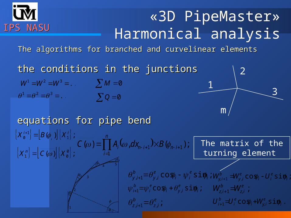
Harmonical analysisThe algorithms for branched and curvelinear elementsThe algorithms for branched and curvelinear elements
1
1
2
2
3
3
4
4 5
1
;,1,e
izb
iz
;sincos,1, ieii
eiy
biy
;sincos ,1 ie
iyiei
bi
;sincos,1 ieii
eiy
biy, UWW
;1eiz,
biz, WW
.sincos1 ieiy,i
ei
bi WUU
the conditions in the junctionsthe conditions in the junctions
equations for pipe bend equations for pipe bend
The matrix of the turning element
;)( 11
0ii XBX
i
;)( 001 XCX n
;)(,)( 11
1
in
n
iini BdxAC
...321 WWW
...321 0M
0Q
1
2
3
m
IPS NASUIPS NASU«3D PipeMaster»
Harmonical analysis«3D PipeMaster»
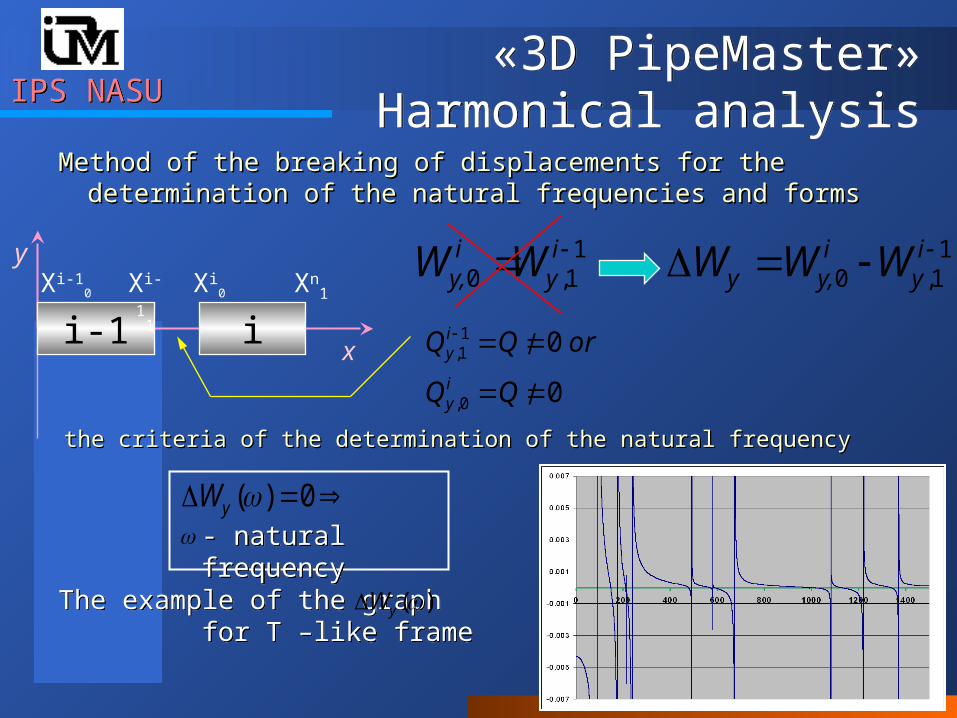
Harmonical analysisMethod of the breaking of displacements for the Method of the breaking of displacements for the
determination of the natural frequencies and forms determination of the natural frequencies and forms
0
0
0,
11,
orQQiy
iyx
i-1 iXi-1
0 Xi0Xi-1
1 Xn1
y 11,0 i
yiy, WW 1
1,0 i
yiy,y WWW
the criteria of the determination of the natural frequencythe criteria of the determination of the natural frequency
- natural frequency - natural frequency
0)(yW
The example of the graph for T –like frame The example of the graph for T –like frame
)(yW
IPS NASUIPS NASU«3D PipeMaster»
Harmonical analysis«3D PipeMaster»
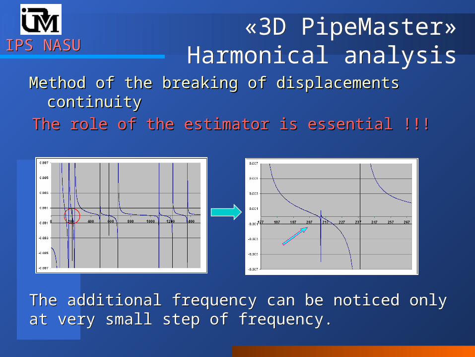
Harmonical analysisMethod of the breaking of displacements continuityMethod of the breaking of displacements continuity
The role of the estimator is essential The role of the estimator is essential !!!!!!
The additional frequency can be noticed only at very small step of frequency. The additional frequency can be noticed only at very small step of frequency.
IPS NASUIPS NASU«3D PipeMaster»
Harmonical analysis«3D PipeMaster»
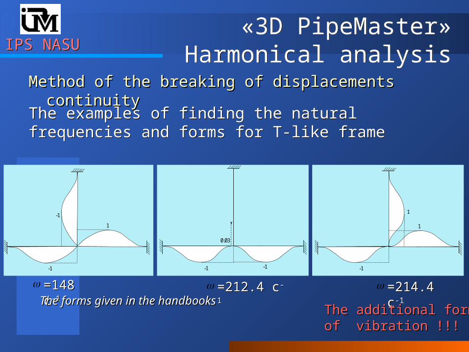
Harmonical analysisMethod of the breaking of displacements continuityMethod of the breaking of displacements continuity
The examples of finding the natural frequencies and forms for T-like frameThe examples of finding the natural frequencies and forms for T-like frame
=148 с-1=148 с-1 =212.4 с-1=212.4 с-1 =214.4 с-1=214.4 с-1
The additional form The additional form of vibrationof vibration !!! !!!
-1
-1
1
0.03
-1 -1
-1
1
1
The forms given in the handbooksThe forms given in the handbooks
IPS NASUIPS NASU«3D PipeMaster»
Harmonical analysis«3D PipeMaster»
Harmonical analysisMethod of the breaking of displacementsMethod of the breaking of displacements
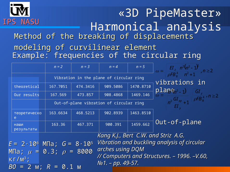
modeling of curvilinear elementmodeling of curvilinear elementExample: frequencies of the circular ringExample: frequencies of the circular ring
Е = 2∙106 МПа; G = 8∙105 МПа; = 0.3; = 8000 кг/м3;В0 = 2 м; R = 0.1 м
Е = 2∙106 МПа; G = 8∙105 МПа; = 0.3; = 8000 кг/м3;В0 = 2 м; R = 0.1 м
n = 2 n = 3 n = 4 n = 5
Vibration in the plane of circular ring
theoretical 167.7051 474.3416 909.5086 1470.8710
Our results 167.569 473.857 908.4868 1469.146
Out-of-plane vibration of circular ring
теоретическое 163.6634 468.5213 902.8939 1463.8510
наши результаты 163.36 467.371 900.391 1459.662
Kang K.J., Bert C.W. and Striz A.G.Kang K.J., Bert C.W. and Striz A.G.Vibration and buckling analysis of circular Vibration and buckling analysis of circular arches using DQMarches using DQM// Computers and Structures. – 1996. –V.60, // Computers and Structures. – 1996. –V.60, №№1. 1. – pp. 49-57.– pp. 49-57.
,
11
2
222
40
nnn
FBEI z
2n
vibrations in planevibrations in plane
Out-of-planeOut-of-plane
,
1
1402
22
FB
GI
EI
GIn
nn y
y
кр
2n
IPS NASUIPS NASU«3D PipeMaster»
Harmonical analysis«3D PipeMaster»
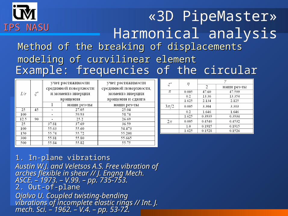
Harmonical analysisMethod of the breaking of displacementsMethod of the breaking of displacementsmodeling of curvilinear elementmodeling of curvilinear elementExample: frequencies of the circular arcExample: frequencies of the circular arc
1. In-plane vibrations Austin W.J. and Veletsos A.S. Free vibration of arches flexible in shear // J. Engng Mech. ASCE. – 1973. – V.99. – pp. 735-753.2. Out-of-plane Ojalvo U. Coupled twisting-bending vibrations of incomplete elastic rings // Int. J. mech. Sci. – 1962. – V.4. – pp. 53-72.
1. In-plane vibrations Austin W.J. and Veletsos A.S. Free vibration of arches flexible in shear // J. Engng Mech. ASCE. – 1973. – V.99. – pp. 735-753.2. Out-of-plane Ojalvo U. Coupled twisting-bending vibrations of incomplete elastic rings // Int. J. mech. Sci. – 1962. – V.4. – pp. 53-72.
IPS NASUIPS NASU«3D PipeMaster»
Harmonical analysis«3D PipeMaster»
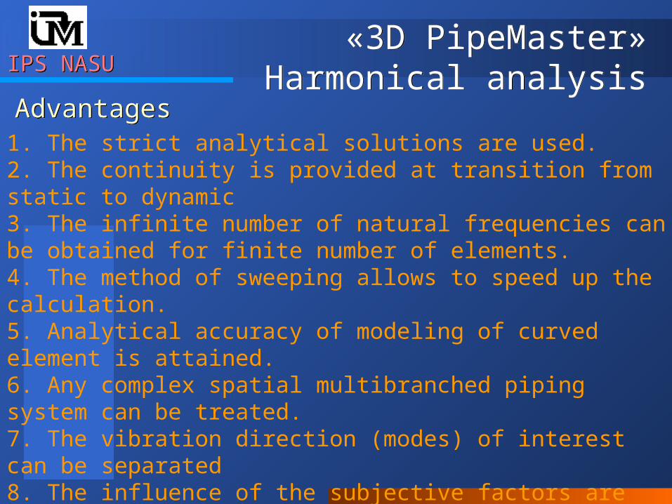
Harmonical analysisAdvantagesAdvantages
1. The strict analytical solutions are used. 2. The continuity is provided at transition from static to dynamic3. The infinite number of natural frequencies can be obtained for finite number of elements.4. The method of sweeping allows to speed up the calculation.5. Analytical accuracy of modeling of curved element is attained.6. Any complex spatial multibranched piping system can be treated.7. The vibration direction (modes) of interest can be separated8. The influence of the subjective factors are excluded (the breaking out on the elements)
IPS NASUIPS NASU
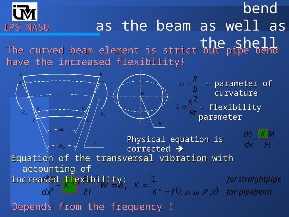
Dynamical model of pipe bend as the beam as well as the shell Dynamical model of pipe bend as the beam as well as the shell
,02
4
4
WEIF
Kdx
Wd d
A
C
B
D
A
C
B
D
zKzK
1d
0d
B
O
R
bendpipeforxPfK
pipestraightforK
д ,,,,
1
BR
BtR2
- flexibility parameter- flexibility parameter
- parameter of curvature - parameter of curvature
The curved beam element is strict but pipe bend have the increased flexibility!The curved beam element is strict but pipe bend have the increased flexibility!
Depends from the frequency !Depends from the frequency !
Physical equation is corrected Physical equation is corrected EIMK
dxd
Equation of the transversal vibration with accounting of increased flexibility:Equation of the transversal vibration with accounting of increased flexibility:
IPS NASUIPS NASU
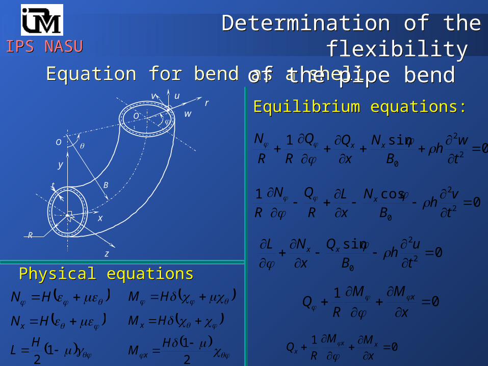
Equation for bend as a shellEquation for bend as a shellr
R
O
B
O1
t
x
y
z
v u
w Equilibrium equations:Equilibrium equations:
0sin1
2
2
0
tw
hB
Nx
RR
Nxx
0cos1
2
2
0
tv
hB
N
xL
R
QN
Rx
0sin
2
2
0
t
uh
B
Q
x
NL xx
01
x
MM
RQ x
01
x
MM
RQ xx
x
HN
HNx
12H
L
HM
HM x
21 H
M x
Physical equationsPhysical equations
Determination of the flexibility of the pipe bend
Determination of the flexibility of the pipe bend
IPS NASUIPS NASU
0
sincos
B
wv
x
u
Rwv
R
1
2
2
xw
22
2
2
1Rww
R
2
2
xw
xw
Rxv
R
222
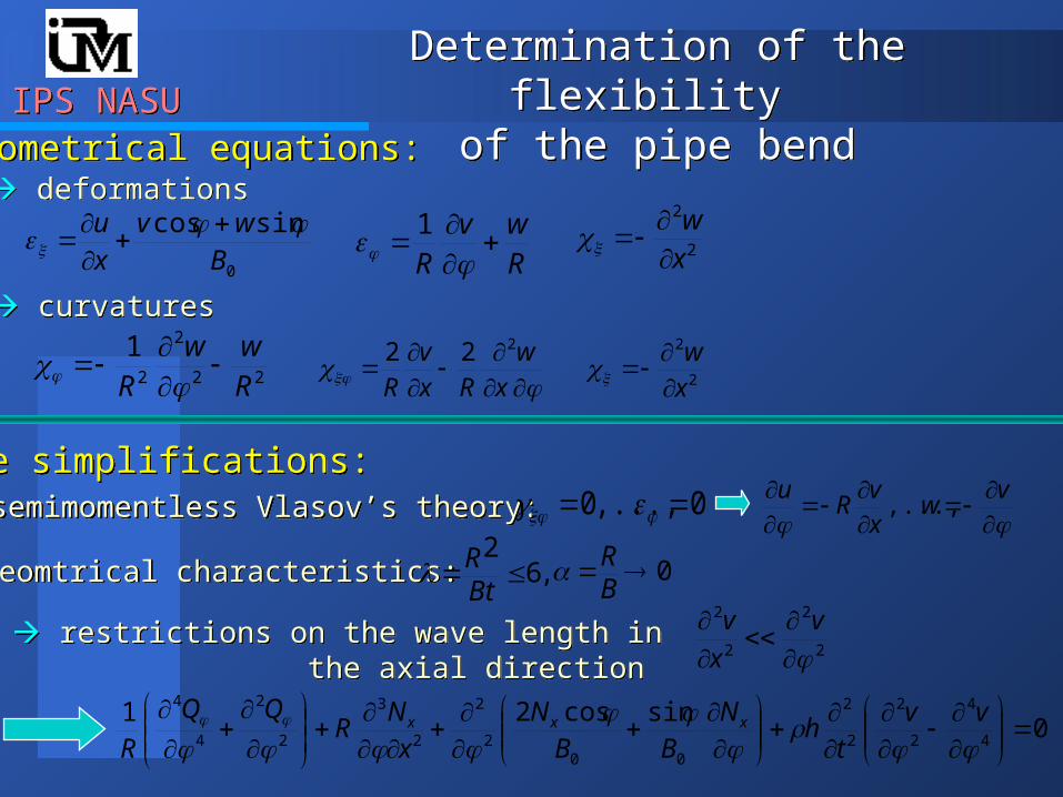
deformations deformations
curvatures curvatures
Geometrical equations:Geometrical equations:
Determination of the flexibility of the pipe bend
Determination of the flexibility of the pipe bend
The simplifications:The simplifications: semimomentless Vlasov’s theory: semimomentless Vlasov’s theory: 0,...,0
v
wxv
Ru
,...,
geomtrical characteristics: geomtrical characteristics: ,62
BtR 0
BR
restrictions on the wave length in the axial direction
restrictions on the wave length in the axial direction
2
2
2
2
v
x
v
0sincos21
4
4
2
2
2
2
002
2
2
3
2
2
4
4
vv
th
N
BB
N
x
NR
Rxxx
IPS NASUIPS NASU
Determination of the flexibility of the pipe bend
Determination of the flexibility of the pipe bend
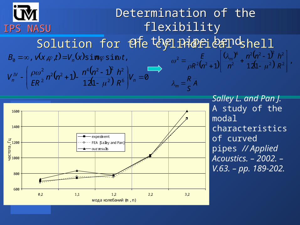
Solution for the cylindrical shellSolution for the cylindrical shell
0112
11
,sinsin,,,
6
2
2
22422
2
2
0
nIV
n
n
VRhnn
nnER
V
tnxVtxvB
ASR
Rhnn
nnRE
m
m
,
1121
1 2
2
2
222
2
4
222
600
800
1000
1200
1400
1600
0,2 1,1 1,2 2,2 3,2
мода колебаний (m, n)
част
ота,
Гц
experiment
FEA [Salley and Pan]
our results
Salley L. and Pan J.A study of the modal characteristics of curved pipes // Applied Acoustics. – 2002. – V.63. – pp. 189-202.
IPS NASUIPS NASU
Determination of the flexibility of the pipe bend
Determination of the flexibility of the pipe bend
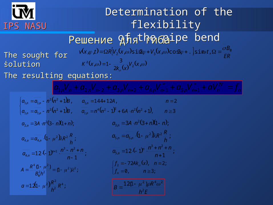
Решение для гибаРешение для гиба
ERB
txVxVRtxv 032 ,sin...3cos,2sin,,,
,2
31, 2 xV
xkxK д
The sought for solutionThe sought for solution::
The resulting equations:The resulting equations:
nIV
nnnnnnnnnnn faVVaVaVaVaVa 1,51,42,32,2,1
3,161,1
2,12144,1
22224,1
22,1,1
,122
,1,1
nnnAnnaBnnaa
nAaBnnaa
nnn
nnn
;133 2,2 nnnAa n
;1 22,4,4 h
RRaa nn
;1
11223
1,4
nnnn
a nn
;)1()1( 22
220
24
hB
RA
;112 42
22 R
hR
a
;133 2,3 nnnAa n
;1 22,5,5 h
RRaa nn
;1
11223
,5
nnnn
a nn
;3,0
;2,722
nf
nxAkf
n
Eh
RB
2
242 )1(12
IPS NASUIPS NASU
Determination of the flexibility of the pipe bend
Determination of the flexibility of the pipe bend
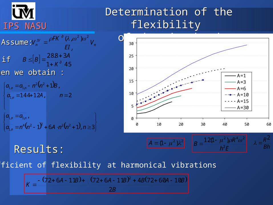
- The coefficient of flexibility at harmonical vibrations
B
BABBABAK
2
10607241167211672 2
22 )1( A
0
5
10
15
20
25
30
0 10 20 30 40 50 60
A=1A=3A=6A=10A=15A=30
K д
B
EhR
B 2
242 )1(12 BhR2
nz
дIV
n VEI
FKV
22 ),( AssumeAssume::
45138.28
дKA
BB
ifif
then we obtain then we obtain ::
3,161
,
2,12144
,1
22224,1
,1,1
,1
22,1,1
nnnAnna
aa
nAa
Bnnaa
n
nn
n
nn
Results:Results:
IPS NASUIPS NASU
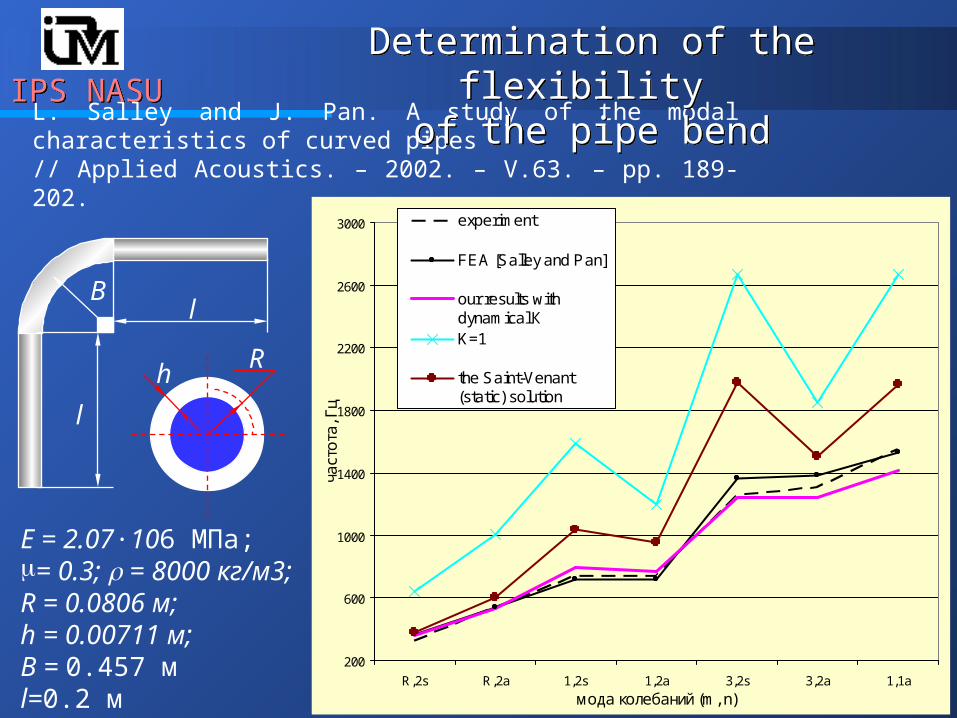
200
600
1000
1400
1800
2200
2600
3000
R,2s R,2a 1,2s 1,2a 3,2s 3,2a 1,1a
мода колебаний (m, n)
част
ота
, Гц
experiment
FEA [Salley and Pan]
our results withdynamical КK=1
the Saint-Venant(static) solution
L. Salley and J. Pan. A study of the modal characteristics of curved pipes // Applied Acoustics. – 2002. – V.63. – pp. 189-202.
Е = 2.07∙106 МПа; = 0.3; = 8000 кг/м3; R = 0.0806 м; h = 0.00711 м;В = 0.457 м l=0.2 м
l
l
Rh
B
Determination of the flexibility of the pipe bend
Determination of the flexibility of the pipe bend
IPS NASUIPS NASU
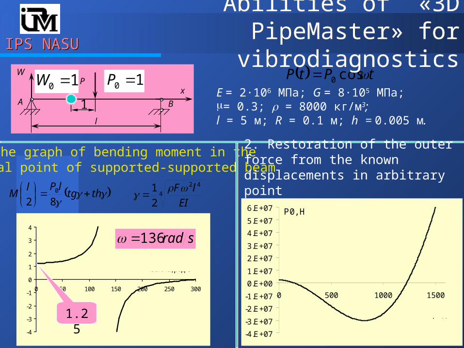
P
A B
l
W
х
thtglPl
M
820 4
42
2
1
EI
lF
tPtP cos0
-4
-3
-2
-1
0
1
2
3
4
0 50 100 150 200 250 300
M(l /2)
частота, рад/c
Е = 2∙106 МПа; G = 8∙105 МПа; = 0.3; = 8000 кг/м3; l = 5 м; R = 0.1 м; h = 0.005 м.
1. The graph of bending moment in the central point of supported-supported beam
srad136
1.25
2. Restoration of the outer force from the known displacements in arbitrary point
P0, H
-4.E+07
-3.E+07
-2.E+07
-1.E+07
0.E+00
1.E+07
2.E+07
3.E+07
4.E+07
5.E+07
6.E+07
0 500 1000 1500
частота, рад/c
1
10 P10 W
Abilities of «3D PipeMaster» for vibrodiagnostics
Abilities of «3D PipeMaster» for vibrodiagnostics
IPS NASUIPS NASUAbilities of «3D PipeMaster» for
vibrodiagnosticsAbilities of «3D PipeMaster» for
vibrodiagnosticsThe problems of vibrodiagnosticsThe problems of vibrodiagnostics1. The points of application of the outer forces, their directions and frequencies are unknown. 2. The gauges can measure the displacements of pipe points, their velocities and accelerations3. The number of gauges is finite.
The functions of the calculation softwareThe functions of the calculation software1. The correct determination of the dynamical characteristics. 2. Correct modeling of the piping behavior when the correct measurement data are provided. 3. The best possible assessment of the behavior with restricted input data.4. The best possible assessment of the dynamical stresses based on the incomplete measurements
IPS NASUIPS NASUAbilities of «3D PipeMaster» for
vibrodiagnosticsAbilities of «3D PipeMaster» for
vibrodiagnostics
yy WF ,
A B
ll 20
х
yQWM ,, yQWM ,,
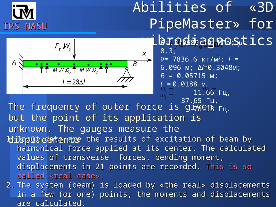
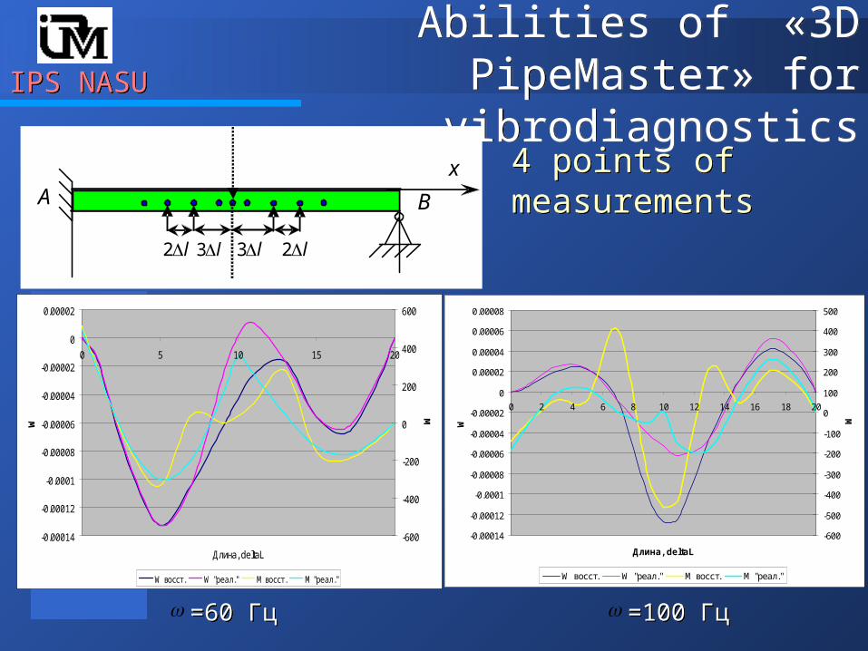
tFtFy sin0Е = 2.0689∙106 МПа; μ= 0.3;= 7836.6 кг/м3; l = 6.096 м; Δl=0.3048м; R = 0.05715 м;t = 0.0188 м. 11.66 Гц, 37.65 Гц, 78.18 Гц.
1 23
1.1. Input data are the results of excitation of beam by harmonical force applied at its Input data are the results of excitation of beam by harmonical force applied at its center. The calculated values of transverse forces, bending moment, displacements center. The calculated values of transverse forces, bending moment, displacements in 21 points are recordedin 21 points are recorded. . This is so called This is so called ««real casereal case».».
2.2. The system (beam) is loaded by The system (beam) is loaded by ««the realthe real» » displacements in a few (or one) pointsdisplacements in a few (or one) points, , the moments and displacements are calculatedthe moments and displacements are calculated..
3.3. The calculated in 2 results are compared with The calculated in 2 results are compared with ««real datareal data».».
The frequency of outer force is given but the point of its application is unknown. The gauges measure the displacements
The frequency of outer force is given but the point of its application is unknown. The gauges measure the displacements
IPS NASUIPS NASUAbilities of «3D PipeMaster» for
vibrodiagnosticsAbilities of «3D PipeMaster» for
vibrodiagnostics
A B
х
l3 l3
-0.0008
-0.0007
-0.0006
-0.0005
-0.0004
-0.0003
-0.0002
-0.0001
0
0.0001
0 2 4 6 8 10 12 14 16 18 20
Длина, deltaL
W
-600
-400
-200
0
200
400
600
M
W восст. W "реал." M восст. M "реал."
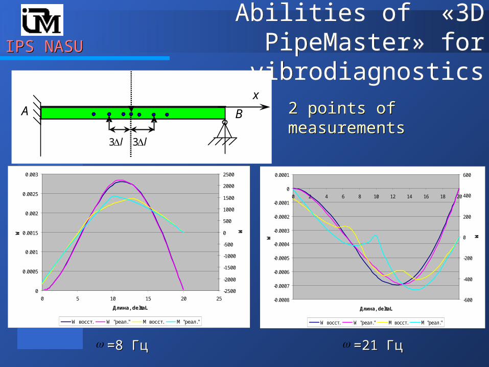
=21 Гц=21 Гц
0
0.0005
0.001
0.0015
0.002
0.0025
0.003
0 5 10 15 20 25
Длина, deltaL
W
-2500
-2000
-1500
-1000
-500
0
500
1000
1500
2000
2500
M
W восст. W "реал." M восст. M "реал."
=8 Гц=8 Гц
2 points of measurements2 points of measurements
IPS NASUIPS NASUAbilities of «3D PipeMaster» for
vibrodiagnosticsAbilities of «3D PipeMaster» for
vibrodiagnostics
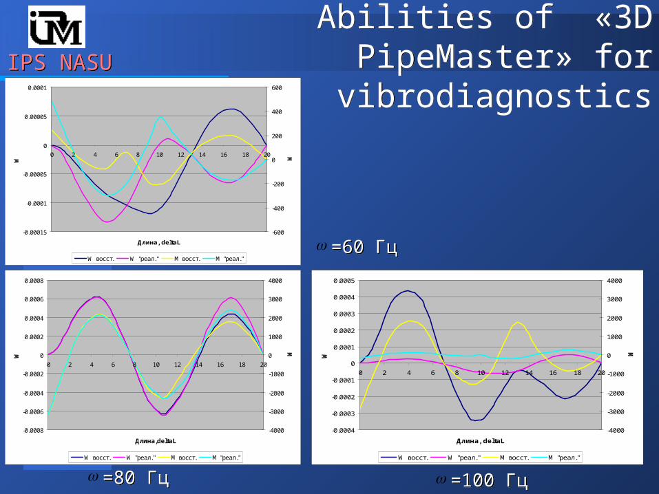
=100 Гц=100 Гц=80 Гц=80 Гц
=60 Гц=60 Гц-0.00015
-0.0001
-0.00005
0
0.00005
0.0001
0 2 4 6 8 10 12 14 16 18 20
Длина, deltaL
W
-600
-400
-200
0
200
400
600
M
W восст. W "реал." M восст. M "реал."
-0.0008
-0.0006
-0.0004
-0.0002
0
0.0002
0.0004
0.0006
0.0008
0 2 4 6 8 10 12 14 16 18 20
Длина,deltaL
W
-4000
-3000
-2000
-1000
0
1000
2000
3000
4000
M
W восст. W "реал." M восст. M "реал."
-0.0004
-0.0003
-0.0002
-0.0001
0
0.0001
0.0002
0.0003
0.0004
0.0005
0 2 4 6 8 10 12 14 16 18 20
Длина, deltaL
W
-4000
-3000
-2000
-1000
0
1000
2000
3000
4000
M
W восст. W "реал." M восст. M "реал."
IPS NASUIPS NASUAbilities of «3D PipeMaster» for
vibrodiagnosticsAbilities of «3D PipeMaster» for
vibrodiagnostics
A B
х
l l
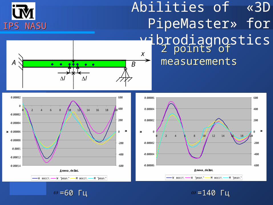
=140 Гц=140 Гц=60 Гц=60 Гц
2 points of measurements2 points of measurements
-0.00014
-0.00012
-0.0001
-0.00008
-0.00006
-0.00004
-0.00002
0
0.00002
0 2 4 6 8 10 12 14 16 18 20
Длина, deltaL
W
-600
-400
-200
0
200
400
600
M
W восст. W "реал." M восст. M "реал."
-0.00006
-0.00004
-0.00002
0
0.00002
0.00004
0.00006
0 2 4 6 8 10 12 14 16 18 20
Длина, deltaL
W
-600
-400
-200
0
200
400
600
M
W восст. W "реал." M восст. M "реал."
IPS NASUIPS NASUAbilities of «3D PipeMaster» for
vibrodiagnosticsAbilities of «3D PipeMaster» for
vibrodiagnostics
=100 Гц=100 Гц=60 Гц=60 Гц
A B
х
l3 l3 l2 l2
4 points of measurements4 points of measurements
-0.00014
-0.00012
-0.0001
-0.00008
-0.00006
-0.00004
-0.00002
0
0.00002
0 5 10 15 20
Длина, deltaL
W
-600
-400
-200
0
200
400
600
M
W восст. W "реал." M восст. M "реал."
-0.00014
-0.00012
-0.0001
-0.00008
-0.00006
-0.00004
-0.00002
0
0.00002
0.00004
0.00006
0.00008
0 2 4 6 8 10 12 14 16 18 20
Длина, deltaL
W
-600
-500
-400
-300
-200
-100
0
100
200
300
400
500
M
W восст. W "реал." M восст. M "реал."
IPS NASUIPS NASUAbilities of «3D PipeMaster» for
vibrodiagnosticsAbilities of «3D PipeMaster» for
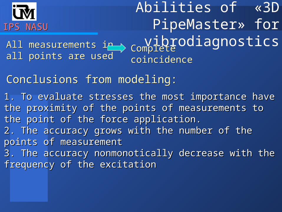
vibrodiagnosticsAll measurements in all points are used All measurements in all points are used
Complete coincidenceComplete coincidence
Conclusions from modeling:Conclusions from modeling:
1. 1. To evaluate stresses the most importance have the To evaluate stresses the most importance have the proximity of the points of measurements to the point of proximity of the points of measurements to the point of the force applicationthe force application..2. 2. The accuracy grows with the number of the points of The accuracy grows with the number of the points of measurement measurement 3. 3. The accuracy nonmonotically decrease with the The accuracy nonmonotically decrease with the frequency of the excitationfrequency of the excitation
1
,2
form
formMAXt
MAX
C
ECW
IPS NASUIPS NASUAbilities of «3D PipeMaster» for
vibrodiagnosticsAbilities of «3D PipeMaster» for
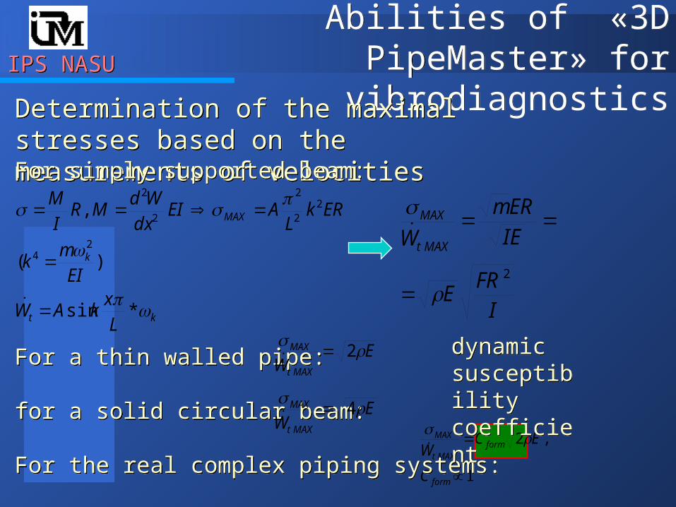
vibrodiagnosticsDetermination of the maximal stresses based on the measurements of velocities Determination of the maximal stresses based on the measurements of velocities
kt
k
MAX
Lx
kAW
EI
mk
ERkL
AEIdx
WdMR
IM
*sin
)(
,
24
22
2
2
2
For simply supported beam:For simply supported beam:
IFR
E
IE
ERm
W MAXt
MAX
2
For a thin walled pipe:
for a solid circular beam:
For the real complex piping systems:
For a thin walled pipe:
for a solid circular beam:
For the real complex piping systems:
EW MAXt
MAX 2
EW MAXt
MAX 4
dynamic susceptibility coefficient
dynamic susceptibility coefficient
IPS NASUIPS NASUAbilities of «3D PipeMaster» for
vibrodiagnosticsAbilities of «3D PipeMaster» for
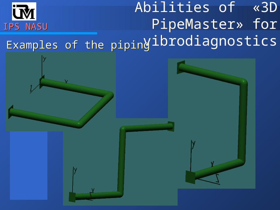
vibrodiagnosticsExamples of the piping configurationExamples of the piping configuration

IPS NASUIPS NASUAbilities of «3D PipeMaster» for
vibrodiagnosticsAbilities of «3D PipeMaster» for
vibrodiagnosticsDetermination of the maximal stresses based on the measurements of velocitiesDetermination of the maximal stresses based on the measurements of velocities
Е = 2.06843∙106 МПа;= 7834 кг/м3; l = 18 м;R = 0.1 м; t = 0.01 м.
J. C. Wachel, Scott J. Morton, Kenneth E. Atkins. Piping vibration analysis
msPа
10*98.5 7 MAXt
MAX
W
Theoretical value:Theoretical value:
IPS NASUIPS NASUAbilities of «3D PipeMaster» for
vibrodiagnosticsAbilities of «3D PipeMaster» for
vibrodiagnosticsDetermination of the maximal stresses based on the measurements of velocitiesDetermination of the maximal stresses based on the measurements of velocities
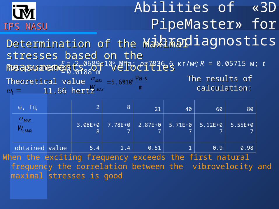
When the exciting frequency exceeds the first natural frequency the correlation between the vibrovelocity and maximal stresses is good
Е = 2.0689∙106 МПа; ρ=7836.6 кг/м3; R = 0.05715 м; t = 0.0188 mFor parametersFor parameters
Theoretical value 11.66 hertzTheoretical value 11.66 hertz m
Pа10*5.69 7 s
W MAXt
MAX
ω, Гц 2 8 21 40 60 80
3.08E+08 7.78E+07 2.87E+07 5.71E+07 5.12E+07 5.55E+07
obtained value 5.4 1.4 0.51 1 0.9 0.98
MAXt
MAX
W
The results of calculation:The results of calculation:
1
IPS NASUIPS NASU Conclusion Conclusion
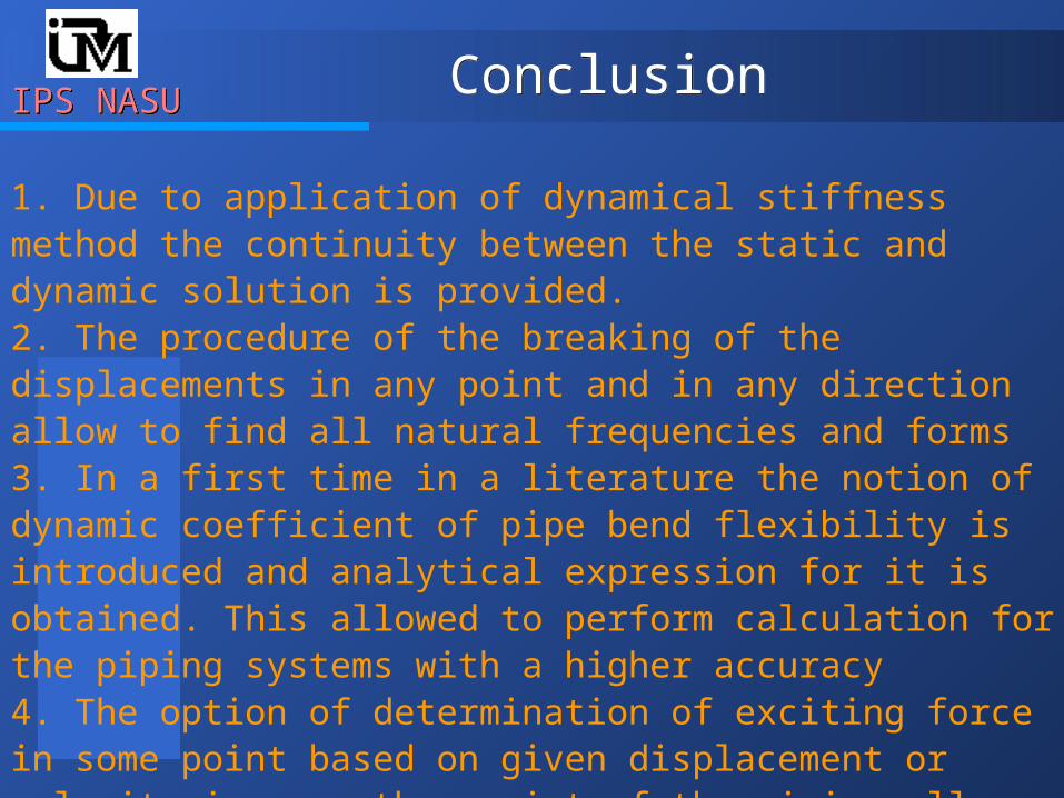
1. Due to application of dynamical stiffness method the continuity between the static and dynamic solution is provided.2. The procedure of the breaking of the displacements in any point and in any direction allow to find all natural frequencies and forms3. In a first time in a literature the notion of dynamic coefficient of pipe bend flexibility is introduced and analytical expression for it is obtained. This allowed to perform calculation for the piping systems with a higher accuracy4. The option of determination of exciting force in some point based on given displacement or velocity in any other point of the piping allows to efficiently perform the vibrodiagnostic analysis


![[Destunis G.S.] Ob Armure(BookZZ.org)](https://img.pdfslide.us/doc/110x75/577ca4d11a28abea748b4726/destunis-gs-ob-armurebookzzorg.jpg)