Embed Size (px)
Citation preview
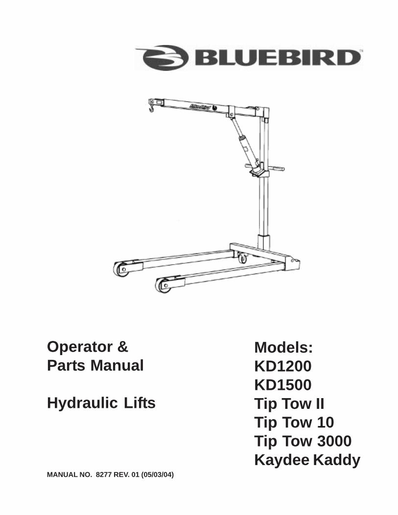
MANUAL NO. 8277 REV. 01 (05/03/04)
Operator &Parts Manual
Hydraulic Lifts
Models:KD1200KD1500Tip Tow IITip Tow 10Tip Tow 3000Kaydee Kaddy

2
3
INDEX
Specifications......................................... 4Illustrations ............................................. 5Safety ..................................................... 6Instructions............................................. 7Trouble shooting .................................... 8Maintenance ........................................... 93 Ton Jack Model 4351 (Parts) .............. 10-115 Ton Jack Model 4451 (Parts) .............. 12-13Assembly Instructionsfor Knockdown Lift ................................. 14-15Kaydee 1200 & 1500 (Parts) ................. 16-17Tip-Tow II, Tip-Tow 3000,Tip-Tow 10 (Parts) .................................. 18-19Kaydee Kaddy Assembly & Storing ....... 20-21Kaydee Kaddy (Parts) ............................ 22-23
©2004 BlueBird International. All Right Reserved.Beatrice, NE. Printed in the U.S.A.
4
SPECIFICATIONS
Capacity Net Weight(lbs)
ShippingWeight (lbs)
Width(inches)
Overall reach(inches)
Length(inches)
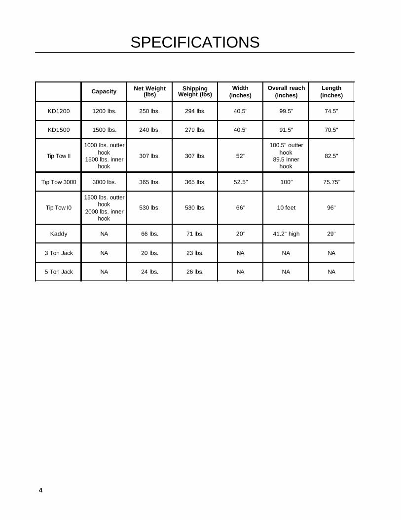
KD1200 1200 lbs. 250 lbs. 294 lbs. 40.5" 99.5" 74.5"
KD1500 1500 lbs. 240 lbs. 279 lbs. 40.5" 91.5" 70.5"
Tip Tow II
1000 lbs. outterhook
1500 lbs. innerhook
307 lbs. 307 lbs. 52"
100.5" outterhook
89.5 innerhook
82.5"
Tip Tow 3000 3000 lbs. 365 lbs. 365 lbs. 52.5" 100" 75.75"
Tip Tow I0
1500 lbs. outterhook
2000 lbs. innerhook
530 lbs. 530 lbs. 66" 10 feet 96"
Kaddy NA 66 lbs. 71 lbs. 20" 41.2" high 29"
3 Ton Jack NA 20 lbs. 23 lbs. NA NA NA
5 Ton Jack NA 24 lbs. 26 lbs. NA NA NA
5
ILLUSTRATIONS
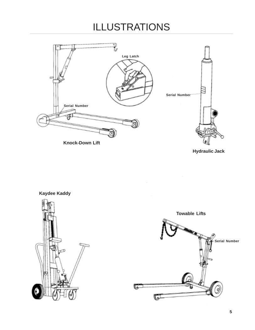
Knock-Down Lift
Hydraulic Jack
Kaydee Kaddy
Towable Lifts
Serial Number
Serial Number
Serial Number
Leg Latch
6
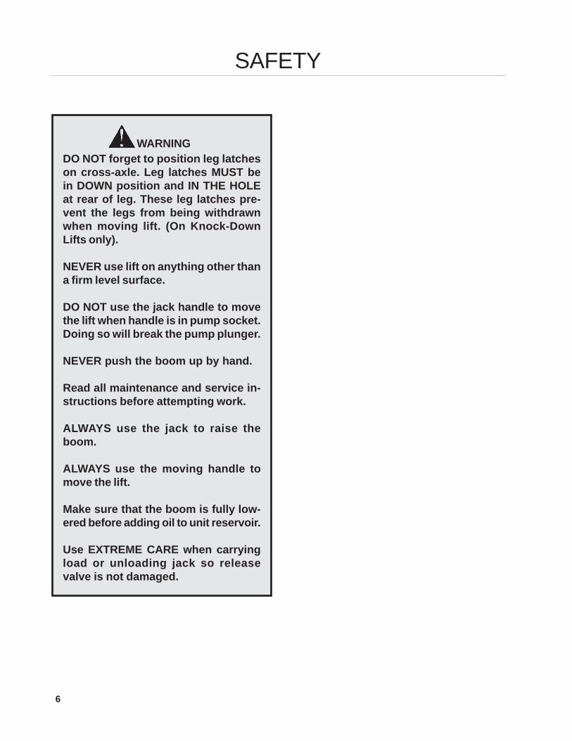
WARNINGDO NOT forget to position leg latcheson cross-axle. Leg latches MUST bein DOWN position and IN THE HOLEat rear of leg. These leg latches pre-vent the legs from being withdrawnwhen moving lift. (On Knock-DownLifts only).
NEVER use lift on anything other thana firm level surface.
DO NOT use the jack handle to movethe lift when handle is in pump socket.Doing so will break the pump plunger.
NEVER push the boom up by hand.
Read all maintenance and service in-structions before attempting work.
ALWAYS use the jack to raise theboom.
ALWAYS use the moving handle tomove the lift.
Make sure that the boom is fully low-ered before adding oil to unit reservoir.
Use EXTREME CARE when carryingload or unloading jack so releasevalve is not damaged.
SAFETY
7
INSTRUCTIONS
TOWING:
1. Release jack to lower boom to the lowest point.2. Place chain hook into hookup point at center
of base of the lift.3. Take up slack in chain by placing lock chain
into the rear grab hook on boom.4. Pump the jack up until chain is tight.
The above instructions will:
• Prevent the boom from “jackknifing” when be-ing towed. Other wise the jack can becomeinoperative because of air being pulled underthe plunger (ram).
• Position the boom correctly so that the cou-pler is horizontal to the ground and at the properheight for towing.
STORAGE:
1. Clean unit.2. Cover all scratches with touch up paint.3, Grease all wheels so they turn freely.4. Store jack indoors.
LIFT MAINTENANCE:1. Grease wheels and casters periodically to in-
sure free movement.2. For jack maintenance, see jack maintenance
section.
3 & 5 TON JACKS:These jacks are manufactured exclusively for theuse on BlueBird hydraulic lifts. The finest available,it incorporates two unique features: An internalsafety bypass valve and a slow release valve.
The bypass valve is set at the factory and SHOULDNOT BE TAMPERED WITH. This valve becomesoperative as the load reaches the capacity of thelift. It then bypasses the hydraulic fluid from thepump into the reservoir so that no greater pres-sure may be exerted on the ram, regardless of theload being lifted. This averts possible damage tothe jack or the lift itself.
The specially engineered slow release valve isdesigned to provide the operator with completecontrol when lowering the load. This restricts thereturn flow of hydraulic fluid so the load will neverdrop suddenly or too fast. To aid in the preventionof accidental removal or the possibility of over tight-ening of the release valve, a STOP has beenwelded to the jack mounting plate. Never removethe stop, if it should become damaged or brokenoff, replace immediately.
8
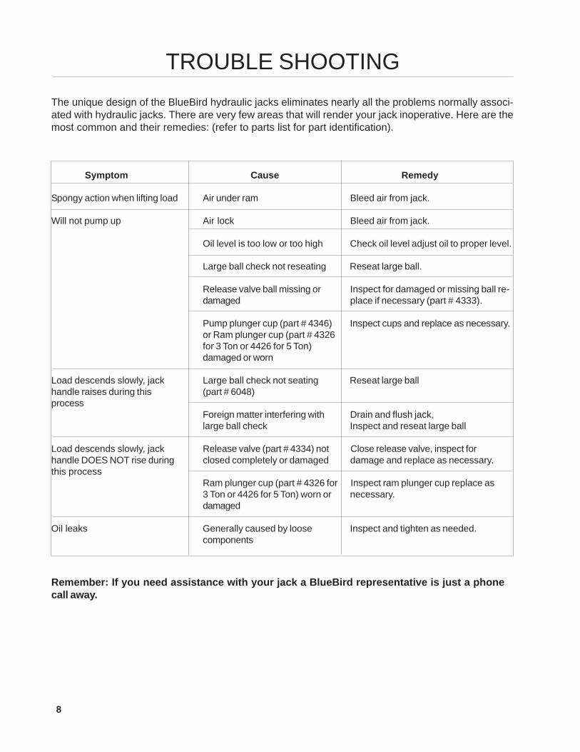
TROUBLE SHOOTING
Symptom Cause Remedy
Spongy action when lifting load Air under ram Bleed air from jack.
Will not pump up Air lock Bleed air from jack.
Oil level is too low or too high Check oil level adjust oil to proper level.
Large ball check not reseating Reseat large ball.
Release valve ball missing or Inspect for damaged or missing ball re-damaged place if necessary (part # 4333).
Pump plunger cup (part # 4346) Inspect cups and replace as necessary.or Ram plunger cup (part # 4326for 3 Ton or 4426 for 5 Ton)damaged or worn
Load descends slowly, jack Large ball check not seating Reseat large ballhandle raises during this (part # 6048)process
Foreign matter interfering with Drain and flush jack,large ball check Inspect and reseat large ball
Load descends slowly, jack Release valve (part # 4334) not Close release valve, inspect forhandle DOES NOT rise during closed completely or damaged damage and replace as necessary.this process
Ram plunger cup (part # 4326 for Inspect ram plunger cup replace as3 Ton or 4426 for 5 Ton) worn or necessary.damaged
Oil leaks Generally caused by loose Inspect and tighten as needed.components
Remember: If you need assistance with your jack a BlueBird representative is just a phonecall away.
The unique design of the BlueBird hydraulic jacks eliminates nearly all the problems normally associ-ated with hydraulic jacks. There are very few areas that will render your jack inoperative. Here are themost common and their remedies: (refer to parts list for part identification).
9
MAINTENANCEHydraulic Jack:
1. Never carry jack by ram or upside-down, thiswill cause air under plunger.
2. Always use only top grade hydraulic oil, neveruse brake fluid!
3. Always insure proper level of hydraulic fluid.Do not overfill reservoir! This will render jackinoperative. Oil should only be filled to the fillerplug. If you should overfill, simply stand jackupright and remove filler plug and allow excessoil to drain from jack through the filler plug. Thecorrect oil level is up to the filler plug.
4. Do not store jack outside.5. Inspect periodically to insure no moisture or
water has collected in jack. Rust will destroyyour jack.
6. Abusive handling may cause damage to thejack. Always handle with care.
7. Load test your lift periodically to insure jackbypasses at specified load limit. Determine loadlimit of your lift, attach a weight equal to 100 lb.greater than load limit. Lift should not lift load. Iflift does lift load, replace safety bypass valveimmediately, do not adjust, bypass valve isset at factory.
Proper maintenance and handling of your hydrau-lic jack will insure many years of service. Here area few tips in the care and maintenance of yourjack.
To Bleed Air From Jack:
(Refer to parts lists for part identification.)
1. Remove jack from lift, lay jack on bench withrelease valve handle in the up position.
2. Remove housing assembly (part # 4330). Usecaution when removing housing assembly soas not to lose spring (part # 4359) located justbeneath housing, remove spring.
3. The large ball (part # 6048) is located just un-der the spring. Using a 5/16 x 3” long or longerbolt. (We do not recommend the use of a hard-ened bolt or drift punch, these will damage theball.) Position bolt on top of ball as close to thecenter of the ball as possible and strike firmlywith a 1 lb. hammer, The amount of force toreseat the ball would similar to striking a 16penny nail with a hammer. This action shouldhave caused a new seating ring for the ball.
4. Replace the spring and reinstall the housingassembly.
It is always wise to check and bleed the jack of air.Test jack for proper function and repeat process ifnecessary.
Reseating the Large Ball Check:
1. Remove jack from lift. Open release valve(item 18) and actuate pump (item 22) approxi-mately 10 complete strokes.
2. Close release valve (item 18), actuate pump(item 22) until plunger (item 4) rises 8-10”.
3. Turn jack upside down, open release valve(item 18) push plunger (item 4) back to re-tracted position.
4. Close release valve (item 18) while holdingplunger (item 4) turn right side up.
5. Repeat this process until all air is removed fromjack.
6. Remove filler plug, check proper level of hy-draulic fluid.
10
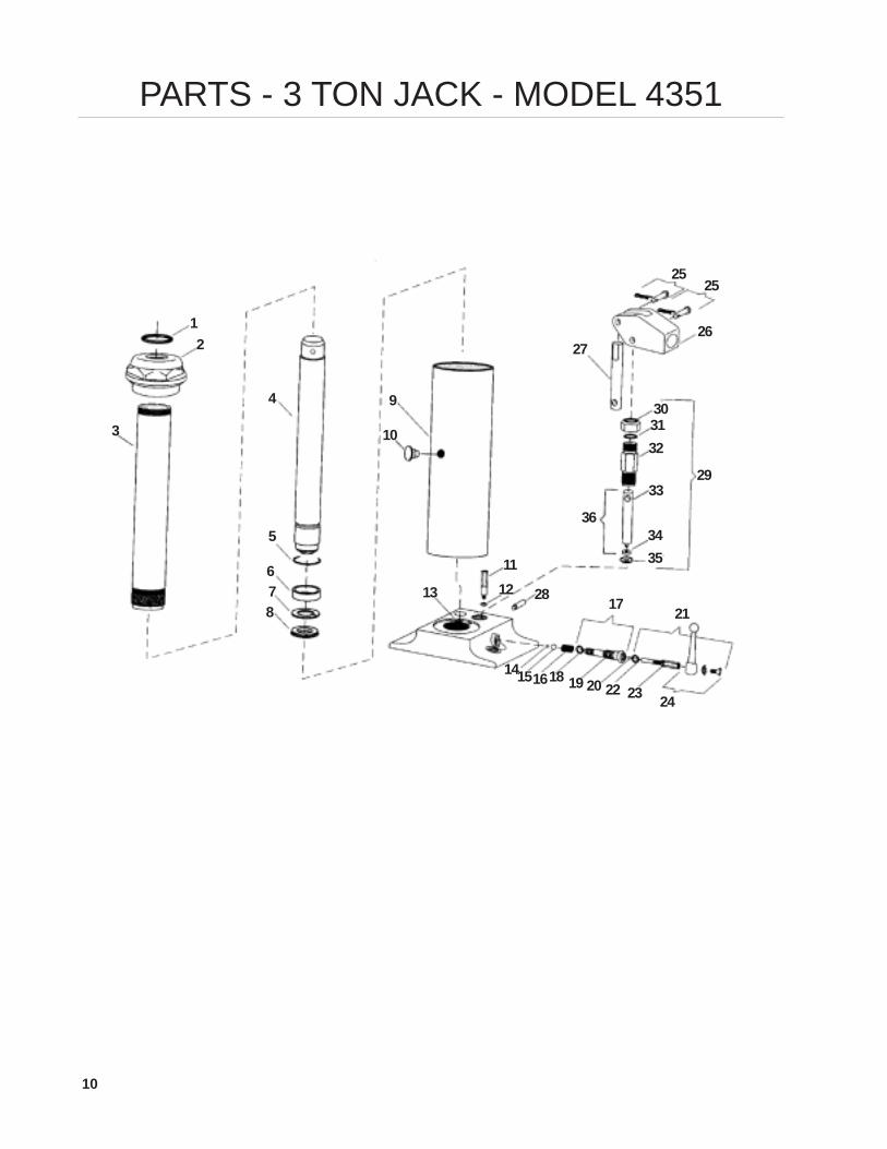
PARTS - 3 TON JACK - MODEL 4351
12
3
4
5
678
9
10
111213
141516
17
18 19 20
21
22 23 24
25
2627
28
29
303132
33
3435
36
25
11
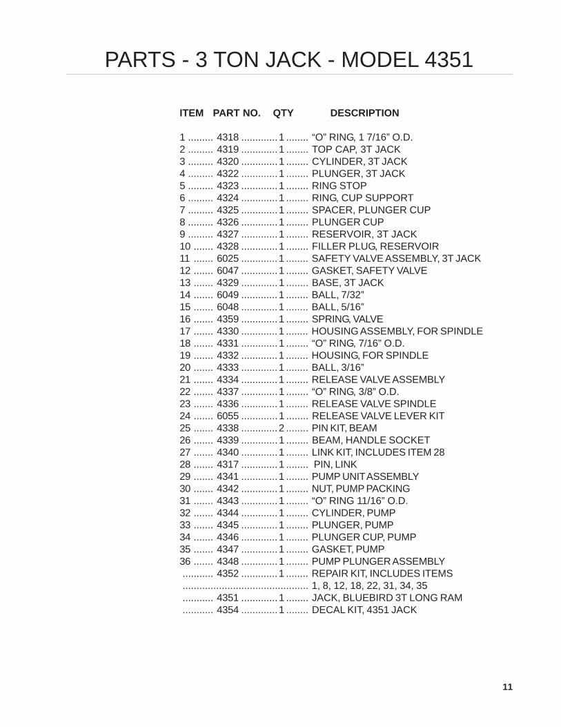
PARTS - 3 TON JACK - MODEL 4351
ITEM PART NO. QTY DESCRIPTION
1 ......... 4318 .............1 ........ “O” RING, 1 7/16” O.D.2 ......... 4319 .............1 ........ TOP CAP, 3T JACK3 ......... 4320 .............1 ........ CYLINDER, 3T JACK4 ......... 4322 .............1 ........ PLUNGER, 3T JACK5 ......... 4323 .............1 ........ RING STOP6 ......... 4324 .............1 ........ RING, CUP SUPPORT7 ......... 4325 .............1 ........ SPACER, PLUNGER CUP8 ......... 4326 .............1 ........ PLUNGER CUP9 ......... 4327 .............1 ........ RESERVOIR, 3T JACK10 ....... 4328 .............1 ........ FILLER PLUG, RESERVOIR11 ....... 6025 .............1 ........ SAFETY VALVE ASSEMBLY, 3T JACK12 ....... 6047 .............1 ........ GASKET, SAFETY VALVE13 ....... 4329 .............1 ........ BASE, 3T JACK14 ....... 6049 .............1 ........ BALL, 7/32”15 ....... 6048 .............1 ........ BALL, 5/16”16 ....... 4359 .............1 ........ SPRING, VALVE17 ....... 4330 .............1 ........ HOUSING ASSEMBLY, FOR SPINDLE18 ....... 4331 .............1 ........ “O” RING, 7/16” O.D.19 ....... 4332 .............1 ........ HOUSING, FOR SPINDLE20 ....... 4333 .............1 ........ BALL, 3/16”21 ....... 4334 .............1 ........ RELEASE VALVE ASSEMBLY22 ....... 4337 .............1 ........ “O” RING, 3/8” O.D.23 ....... 4336 .............1 ........ RELEASE VALVE SPINDLE24 ....... 6055 .............1 ........ RELEASE VALVE LEVER KIT25 ....... 4338 .............2 ........ PIN KIT, BEAM26 ....... 4339 .............1 ........ BEAM, HANDLE SOCKET27 ....... 4340 .............1 ........ LINK KIT, INCLUDES ITEM 2828 ....... 4317 .............1 ........ PIN, LINK29 ....... 4341 .............1 ........ PUMP UNIT ASSEMBLY30 ....... 4342 .............1 ........ NUT, PUMP PACKING31 ....... 4343 .............1 ........ “O” RING 11/16” O.D.32 ....... 4344 .............1 ........ CYLINDER, PUMP33 ....... 4345 .............1 ........ PLUNGER, PUMP34 ....... 4346 .............1 ........ PLUNGER CUP, PUMP35 ....... 4347 .............1 ........ GASKET, PUMP36 ....... 4348 .............1 ........ PUMP PLUNGER ASSEMBLY........... 4352 .............1 ........ REPAIR KIT, INCLUDES ITEMS............................................. 1, 8, 12, 18, 22, 31, 34, 35........... 4351 .............1 ........ JACK, BLUEBIRD 3T LONG RAM........... 4354 .............1 ........ DECAL KIT, 4351 JACK
12
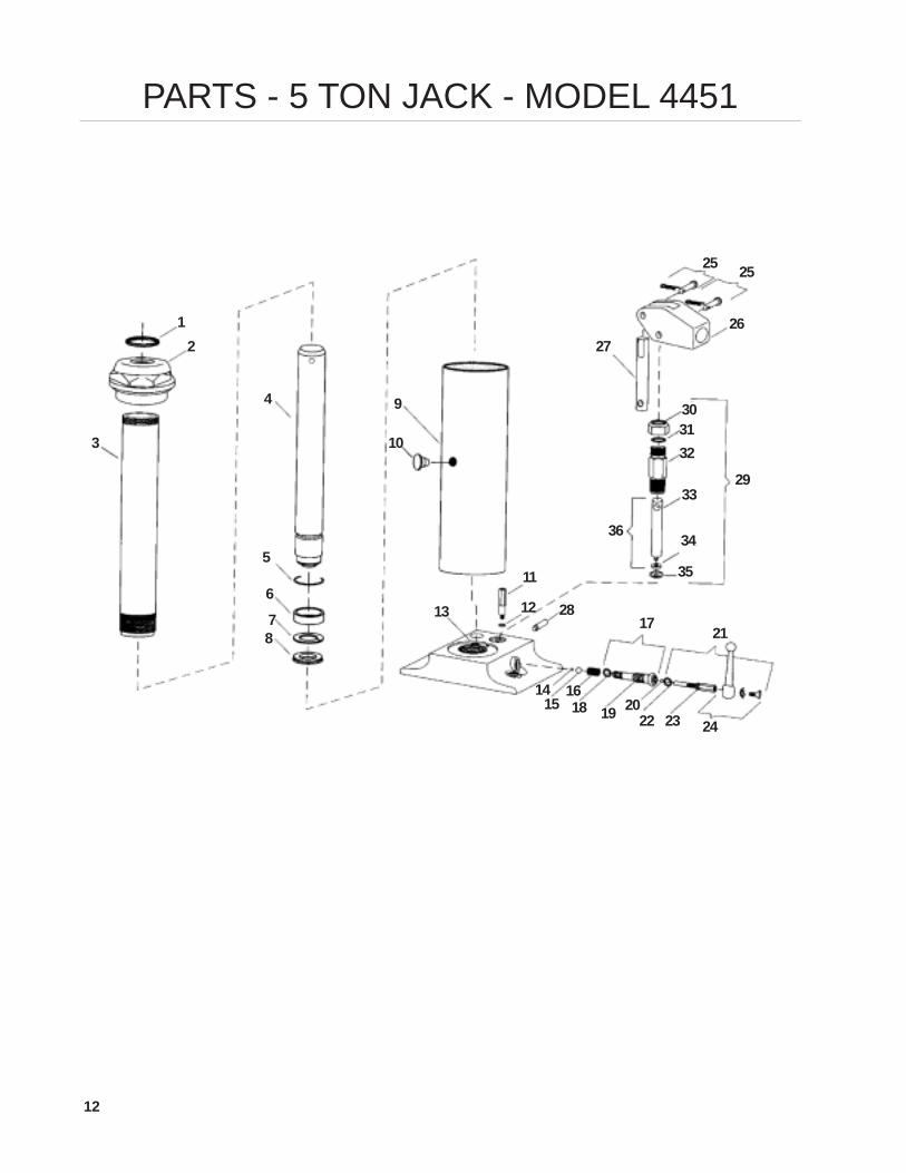
PARTS - 5 TON JACK - MODEL 4451
12
3
4
5
678
9
10
11
1213
1415
16
17
18 19 20
21
22 23 24
25
2627
28
29
30
33
3436
25
35
3231
13
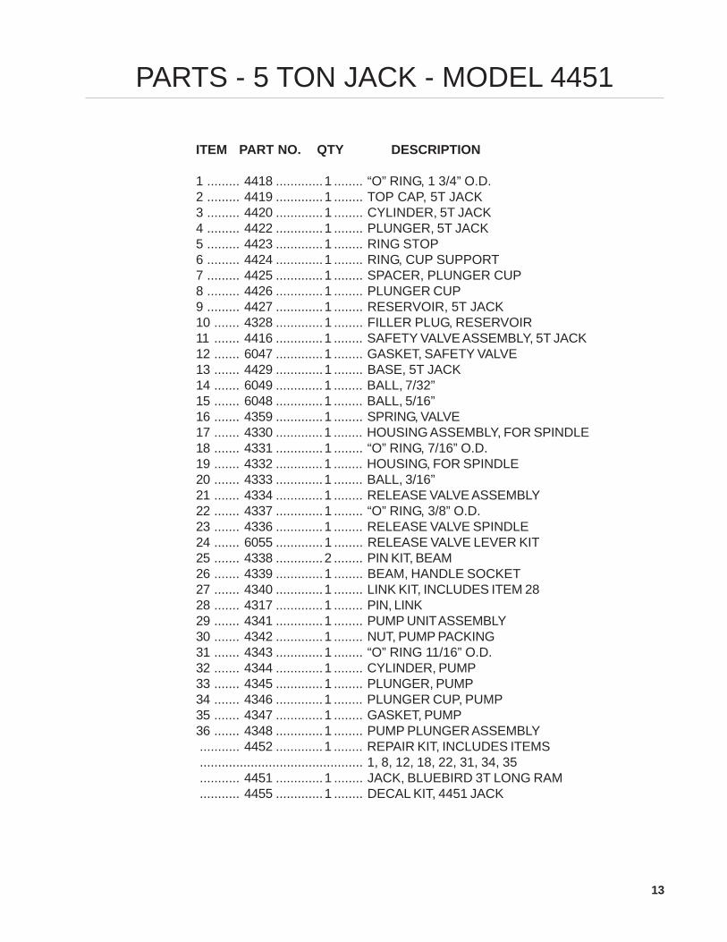
PARTS - 5 TON JACK - MODEL 4451
ITEM PART NO. QTY DESCRIPTION
1 ......... 4418 .............1 ........ “O” RING, 1 3/4” O.D.2 ......... 4419 .............1 ........ TOP CAP, 5T JACK3 ......... 4420 .............1 ........ CYLINDER, 5T JACK4 ......... 4422 .............1 ........ PLUNGER, 5T JACK5 ......... 4423 .............1 ........ RING STOP6 ......... 4424 .............1 ........ RING, CUP SUPPORT7 ......... 4425 .............1 ........ SPACER, PLUNGER CUP8 ......... 4426 .............1 ........ PLUNGER CUP9 ......... 4427 .............1 ........ RESERVOIR, 5T JACK10 ....... 4328 .............1 ........ FILLER PLUG, RESERVOIR11 ....... 4416 .............1 ........ SAFETY VALVE ASSEMBLY, 5T JACK12 ....... 6047 .............1 ........ GASKET, SAFETY VALVE13 ....... 4429 .............1 ........ BASE, 5T JACK14 ....... 6049 .............1 ........ BALL, 7/32”15 ....... 6048 .............1 ........ BALL, 5/16”16 ....... 4359 .............1 ........ SPRING, VALVE17 ....... 4330 .............1 ........ HOUSING ASSEMBLY, FOR SPINDLE18 ....... 4331 .............1 ........ “O” RING, 7/16” O.D.19 ....... 4332 .............1 ........ HOUSING, FOR SPINDLE20 ....... 4333 .............1 ........ BALL, 3/16”21 ....... 4334 .............1 ........ RELEASE VALVE ASSEMBLY22 ....... 4337 .............1 ........ “O” RING, 3/8” O.D.23 ....... 4336 .............1 ........ RELEASE VALVE SPINDLE24 ....... 6055 .............1 ........ RELEASE VALVE LEVER KIT25 ....... 4338 .............2 ........ PIN KIT, BEAM26 ....... 4339 .............1 ........ BEAM, HANDLE SOCKET27 ....... 4340 .............1 ........ LINK KIT, INCLUDES ITEM 2828 ....... 4317 .............1 ........ PIN, LINK29 ....... 4341 .............1 ........ PUMP UNIT ASSEMBLY30 ....... 4342 .............1 ........ NUT, PUMP PACKING31 ....... 4343 .............1 ........ “O” RING 11/16” O.D.32 ....... 4344 .............1 ........ CYLINDER, PUMP33 ....... 4345 .............1 ........ PLUNGER, PUMP34 ....... 4346 .............1 ........ PLUNGER CUP, PUMP35 ....... 4347 .............1 ........ GASKET, PUMP36 ....... 4348 .............1 ........ PUMP PLUNGER ASSEMBLY........... 4452 .............1 ........ REPAIR KIT, INCLUDES ITEMS............................................. 1, 8, 12, 18, 22, 31, 34, 35........... 4451 .............1 ........ JACK, BLUEBIRD 3T LONG RAM........... 4455 .............1 ........ DECAL KIT, 4451 JACK
14
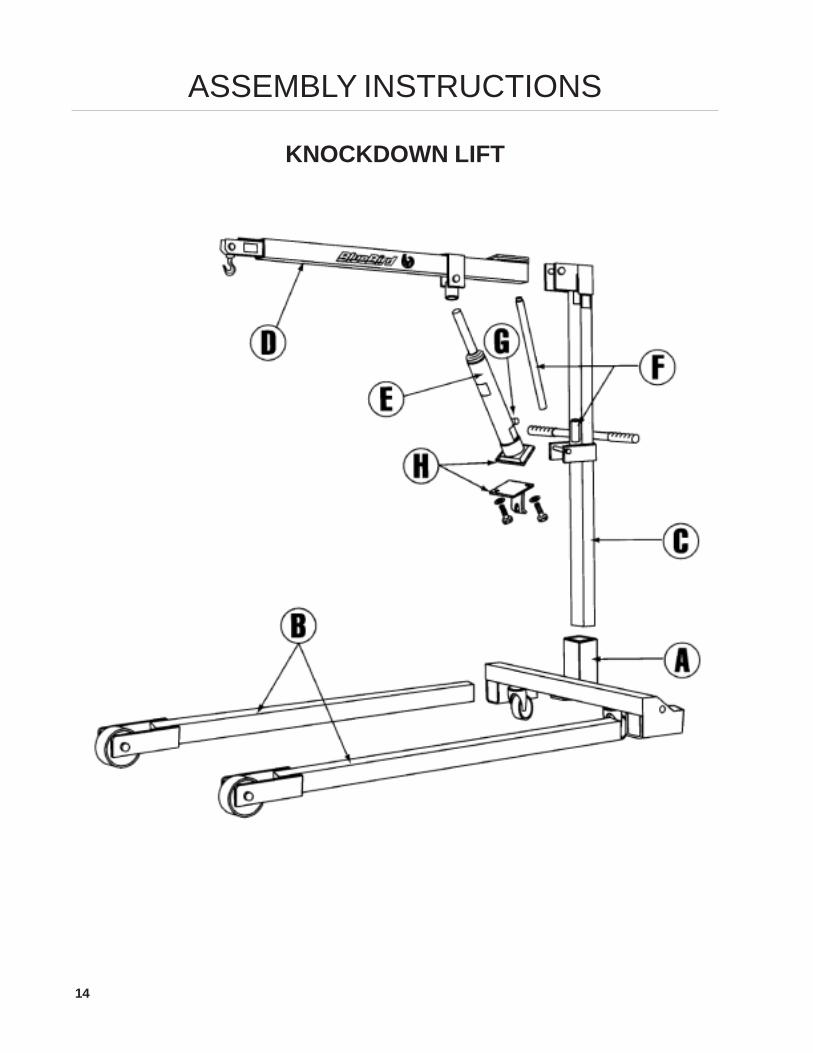
ASSEMBLY INSTRUCTIONS
KNOCKDOWN LIFT
15
• Place cross-axle (A) on level surface.
• Insert legs (B) completely, so that latches snapinto holes in the legs. This is important as thelatches keep the legs from pulling out whenthe lift is moved.
• Insert upright column post (C) into socket incross-axle with flanges facing forward.
• Insert jack handle (F) into handle retainer.
• Hold front end of boom (D) at a high angle andslide boom hook into the pin on the columnpost from bottom side. Lower boom to relaxedposition.
• Bolt base plate to bottom of jack (H).
• Place jack (E) on the pin on column post sothat the pump of the jack (G) next to the col-umn post.
• Place ram of jack into socket on boom.
• Use level firm surface only.
NOTE: Black pins on cross-axle must be inDOWN position and IN THE HOLE at rear oflegs. These pins prevent legs from being with-drawn when moving lift.
ASSEMBLY INSTRUCTIONS

16
PARTS - KAYDEE 1200 & 1500
KNOCKDOWN LIFT
1
2
3
4
5
6
78
9
10
11
12
13
14
15OPTIONAL COLUMN POSTTO COVERT TO SHORT LIFT
17
PARTS - KAYDEE 1200 & 1500
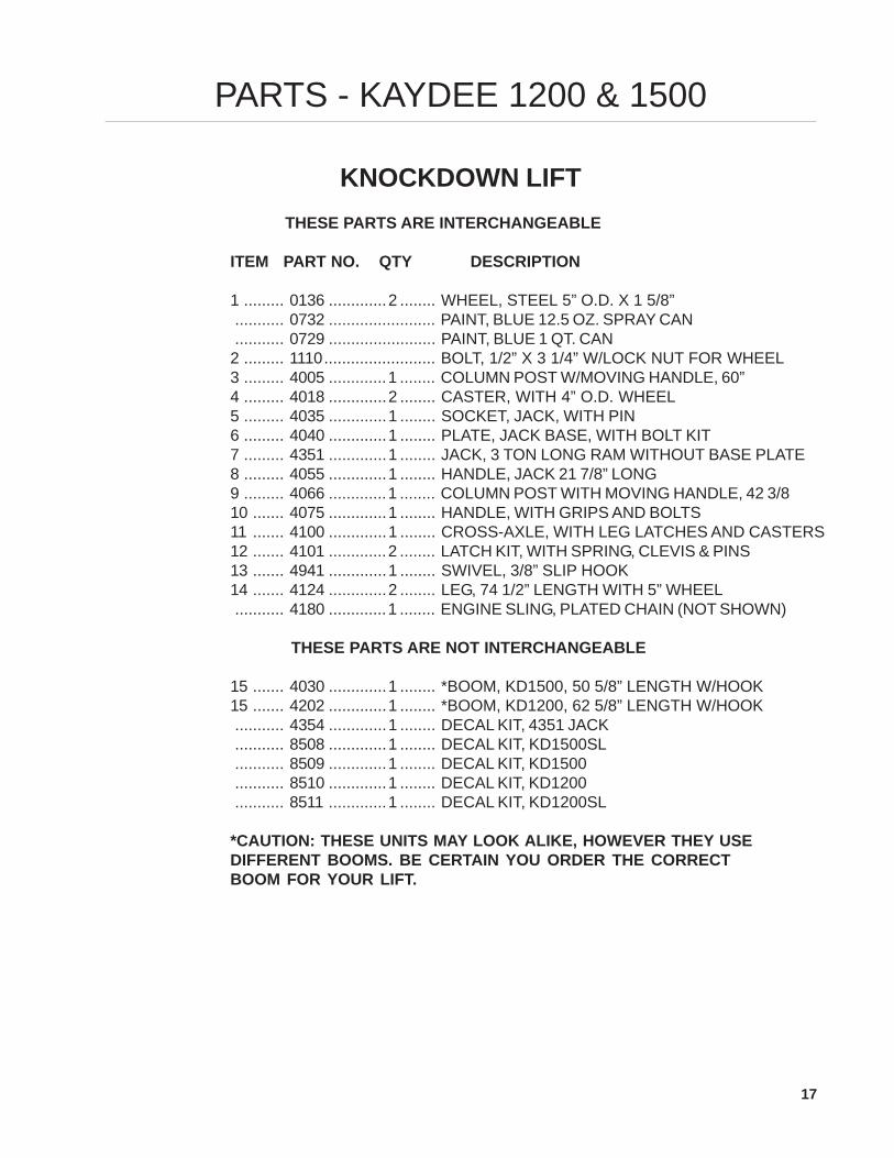
KNOCKDOWN LIFT THESE PARTS ARE INTERCHANGEABLE
ITEM PART NO. QTY DESCRIPTION
1 ......... 0136 .............2 ........ WHEEL, STEEL 5” O.D. X 1 5/8”........... 0732 ........................ PAINT, BLUE 12.5 OZ. SPRAY CAN........... 0729 ........................ PAINT, BLUE 1 QT. CAN
2 ......... 1110......................... BOLT, 1/2” X 3 1/4” W/LOCK NUT FOR WHEEL3 ......... 4005 .............1 ........ COLUMN POST W/MOVING HANDLE, 60”4 ......... 4018 .............2 ........ CASTER, WITH 4” O.D. WHEEL5 ......... 4035 .............1 ........ SOCKET, JACK, WITH PIN6 ......... 4040 .............1 ........ PLATE, JACK BASE, WITH BOLT KIT7 ......... 4351 .............1 ........ JACK, 3 TON LONG RAM WITHOUT BASE PLATE8 ......... 4055 .............1 ........ HANDLE, JACK 21 7/8” LONG9 ......... 4066 .............1 ........ COLUMN POST WITH MOVING HANDLE, 42 3/810 ....... 4075 .............1 ........ HANDLE, WITH GRIPS AND BOLTS11 ....... 4100 .............1 ........ CROSS-AXLE, WITH LEG LATCHES AND CASTERS12 ....... 4101 .............2 ........ LATCH KIT, WITH SPRING, CLEVIS & PINS13 ....... 4941 .............1 ........ SWIVEL, 3/8” SLIP HOOK14 ....... 4124 .............2 ........ LEG, 74 1/2” LENGTH WITH 5” WHEEL........... 4180 .............1 ........ ENGINE SLING, PLATED CHAIN (NOT SHOWN)
THESE PARTS ARE NOT INTERCHANGEABLE
15 ....... 4030 .............1 ........ *BOOM, KD1500, 50 5/8” LENGTH W/HOOK15 ....... 4202 .............1 ........ *BOOM, KD1200, 62 5/8” LENGTH W/HOOK........... 4354 .............1 ........ DECAL KIT, 4351 JACK........... 8508 .............1 ........ DECAL KIT, KD1500SL........... 8509 .............1 ........ DECAL KIT, KD1500........... 8510 .............1 ........ DECAL KIT, KD1200........... 8511 .............1 ........ DECAL KIT, KD1200SL
*CAUTION: THESE UNITS MAY LOOK ALIKE, HOWEVER THEY USEDIFFERENT BOOMS. BE CERTAIN YOU ORDER THE CORRECTBOOM FOR YOUR LIFT.
18
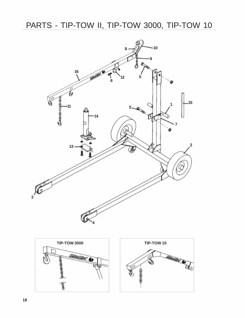
PARTS - TIP-TOW II, TIP-TOW 3000, TIP-TOW 10
TIP-TOW 3000 TIP-TOW 10
1
2
3
4
56
7
8
9
10
11
12
13
14
15
16
5
19
ITEM PART NO. QTY DESCRIPTIONTT II Shop II TT3000 Shop 3000 TT10 Shop 10
1 0025 2 2 2 2 GRIP, PLASTIC 3/4” I.D.1 4670 2 2 GRIP, PLASTIC 1” I.D.2 0045 2 2 WHEEL, W/4.80-8 TIRE & BEARINGS2 0022 2 WHEEL, W/5.70-8 TIRE & BEARINGS3 0136 2 2 2 2 WHEEL, STEEL 5” O.D. X 1 5/8”3 0021 2 2 WHEEL, STEEL 8” O.D. W/ROLLER BEARING4 1110 2 2 2 2 BOLT KIT FOR 5” WHEEL (0136)4 1250 2 2 BOLT KIT FOR 8” WHEEL (0021)5 1212 2 2 2 2 BOLT KIT FOR COLUMN5 4593 2 2 BOLT KIT FOR COLUMN6 1211 1 1 1 1 BOLT KIT FOR SOCKET PLUNGER6 4596 1 1 BOLT KIT FOR SOCKET PLUNGER7 4048 1 1 1 1 1 1 JACK HANDLE RETAINING KIT8 4522 1 1 1 COUPLER, COMPLETE W/KIT, ACCOMMODATES
2” & 2 1/2” BALL LESS CHAIN (4523)9 4523 1 1 1 CHAIN, TOW 3/16” W/RING10 4524 1 1 1 REPAIR KIT, COUPLER11 4525 1 1 1 1 CHAIN, 3/8: W/SLIP HOOK CERTIFIED 5100 LBS.11 4594 1 1 CHAIN, 5/16” SLIP HOOK12 4435 1 1 1 1 SOCKET, PLUNGER W/BOLT KIT13 4440 1 1 1 1 PLATE, JACK BASE W/BOLT KIT13 4595 1 1 PLATE, JACK BASE W/BOLT KIT14 4351 1 1 JACK, BLUEBIRD, 3T LONG RAM14 4451 1 1 1 1 JACK, BLUEBIRD, 5T LONG RAM15 4555 1 1 1 1 1 1 HANDLE, JACK16 4576 1 BOOM, TT 3000, 54” LENGTH W/COUPLER,
HOOKS, DECALS & CHAINS (4525 & 4523)16 4559 1 BOOM, SHOP II, 68” LENGTH W/CHAIN,
HOOKS & DECALS16 4580 1 BOOM, TIP TOW II, 68” LENGTH W/COUPLER,
HOOKS, DECALS & CHAINS (4594 & 4523)16 4660 1 BOOM, TT 10, W/COUPLER, HOOKS
DECALS & CHAINS (4525 & 4523)16 4661 1 BOOM, SHOP 10, W/CHAINS, HOOKS
& DECALS4354 1 1 DECAL KIT, FOR 4351 JACK 3 TON4455 1 1 1 1 DECAL KIT, FOR 4451 JACK 5 TON8504 1 DECAL KIT, SHOP 108505 1 DECAL KIT, TT108506 1 DECAL KIT, TT II8507 1 DECAL KIT, SHOP II8512 1 DECAL KIT, SHOP 30008513 1 DECAL KIT, TT30000732 PAINT, BLUE 12.5 OZ. SPRAY CAN0729 PAINT, BLUE 1 QT. CAN
PARTS - TIP-TOW II, TIP-TOW 3000, TIP-TOW 10
20
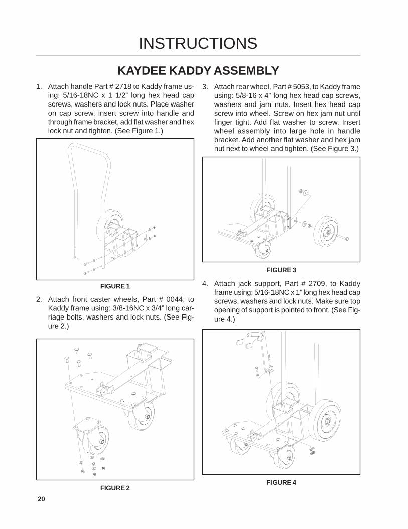
1. Attach handle Part # 2718 to Kaddy frame us-ing: 5/16-18NC x 1 1/2” long hex head capscrews, washers and lock nuts. Place washeron cap screw, insert screw into handle andthrough frame bracket, add flat washer and hexlock nut and tighten. (See Figure 1.)
INSTRUCTIONSKAYDEE KADDY ASSEMBLY
3. Attach rear wheel, Part # 5053, to Kaddy frameusing: 5/8-16 x 4” long hex head cap screws,washers and jam nuts. Insert hex head capscrew into wheel. Screw on hex jam nut untilfinger tight. Add flat washer to screw. Insertwheel assembly into large hole in handlebracket. Add another flat washer and hex jamnut next to wheel and tighten. (See Figure 3.)
FIGURE 1
2. Attach front caster wheels, Part # 0044, toKaddy frame using: 3/8-16NC x 3/4” long car-riage bolts, washers and lock nuts. (See Fig-ure 2.)
FIGURE 2
FIGURE 3
4. Attach jack support, Part # 2709, to Kaddyframe using: 5/16-18NC x 1” long hex head capscrews, washers and lock nuts. Make sure topopening of support is pointed to front. (See Fig-ure 4.)
FIGURE 4
21
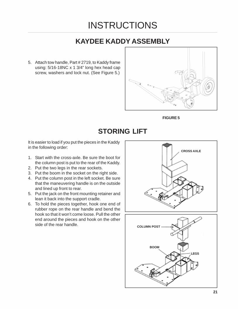
5. Attach tow handle, Part # 2719, to Kaddy frameusing: 5/16-18NC x 1 3/4” long hex head capscrew, washers and lock nut. (See Figure 5.)
INSTRUCTIONSKAYDEE KADDY ASSEMBLY
FIGURE 5
STORING LIFTIt is easier to load if you put the pieces in the Kaddyin the following order:
1. Start with the cross-axle. Be sure the boot forthe column post is put to the rear of the Kaddy.
2. Put the two legs in the rear sockets.3. Put the boom in the socket on the right side.4. Put the column post in the left socket. Be sure
that the maneuvering handle is on the outsideand lined up front to rear.
5. Put the jack on the front mounting retainer andlean it back into the support cradle.
6. To hold the pieces together, hook one end ofrubber rope on the rear handle and bend thehook so that it won’t come loose. Pull the otherend around the pieces and hook on the otherside of the rear handle.
CROSS AXLE
COLUMN POST
BOOM
LEGS
22
PARTS
1
2
3
4
5
6
7
8
9
10
23
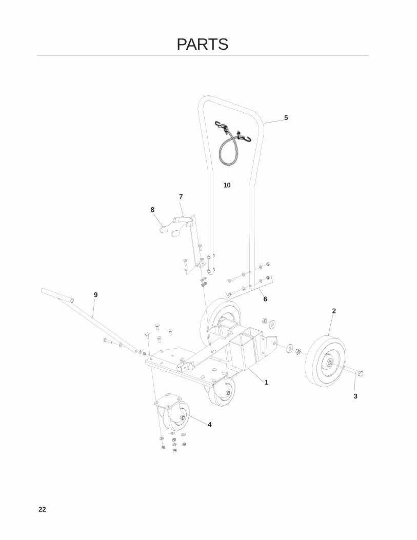
ITEM PART NO. QTY DESCRIPTION
1 ......... 2701 .............1 ........ FRAME, KADDY2 ......... 5053 .............2 ........ WHEEL, 10” X 2.75” SEMI-PNEUMATIC, BALL BEARING3 ......... 5054 .............2 ........ BOLT KIT, WHEEL 5/8” X 4” BOLT W/ NUTS & WASHERS4 ......... 2737 .............2 ........ CASTER, 6” W/BOLT KIT5 ......... 2718 .............1 ........ HANDLE, REAR6 ......... 2723 .............1 ........ BOLT KIT, REAR HANDLE, 4 EACH 5/16” X 1 1/2”............................................. W/WASHERS & LOCK NUTS7 ......... 2738 .............1 ........ SUPPORT, JACK W/BOLT KIT8 ......... 5009 .............2 ........ PLASTIC CAP9 ......... 2719 .............1 ........ HANDLE, PULL W/BOLT WASHER & LOCK NUT10 ....... 2734 .............1 ........ STRAP, RUBBER W/HOOKS........... 0732 ........................ PAINT, BLUE 12.5 OZ. SPRAY CAN........... 0729 ........................ PAINT, BLUE 1 QT. CAN........... 8514 .............1 ........ DECAL KIT, BLUEBIRD KAYDEE KADDY
PARTS

P.O. Box 8Beatrice, Nebraska 68310


![Tow Manual [eBook]](https://img.pdfslide.us/doc/110x75/577d2fb61a28ab4e1eb272f7/tow-manual-ebook.jpg)