Embed Size (px)
Citation preview
SOLIDWORKS PLASTICS
Introduction
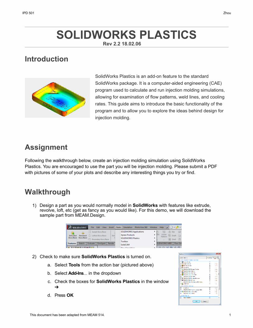
SolidWorks Plastics is an add-on feature to the standard SolidWorks package. It is a computer-aided engineering (CAE) program used to calculate and run injection molding simulations, allowing for examination of flow patterns, weld lines, and cooling rates. This guide aims to introduce the basic functionality of the program and to allow you to explore the ideas behind design for injection molding.
Assignment Following the walkthrough below, create an injection molding simulation using SolidWorks Plastics. You are encouraged to use the part you will be injection molding. Please submit a PDF with pictures of some of your plots and describe any interesting things you try or find.
Walkthrough 1) Design a part as you would normally model in SolidWorks with features like extrude,
revolve, loft, etc (get as fancy as you would like). For this demo, we will download thesample part from MEAM.Design.
2) Check to make sure SolidWorks Plastics is turned on.
a. Select Tools from the action bar (pictured above)
b. Select Add-Ins... in the dropdown
c. Check the boxes for SolidWorks Plastics in the window➔
d. Press OK
Rev 2.2 18.02.06
IPD 501 Zhou
1This document has been adapted from MEAM 514.
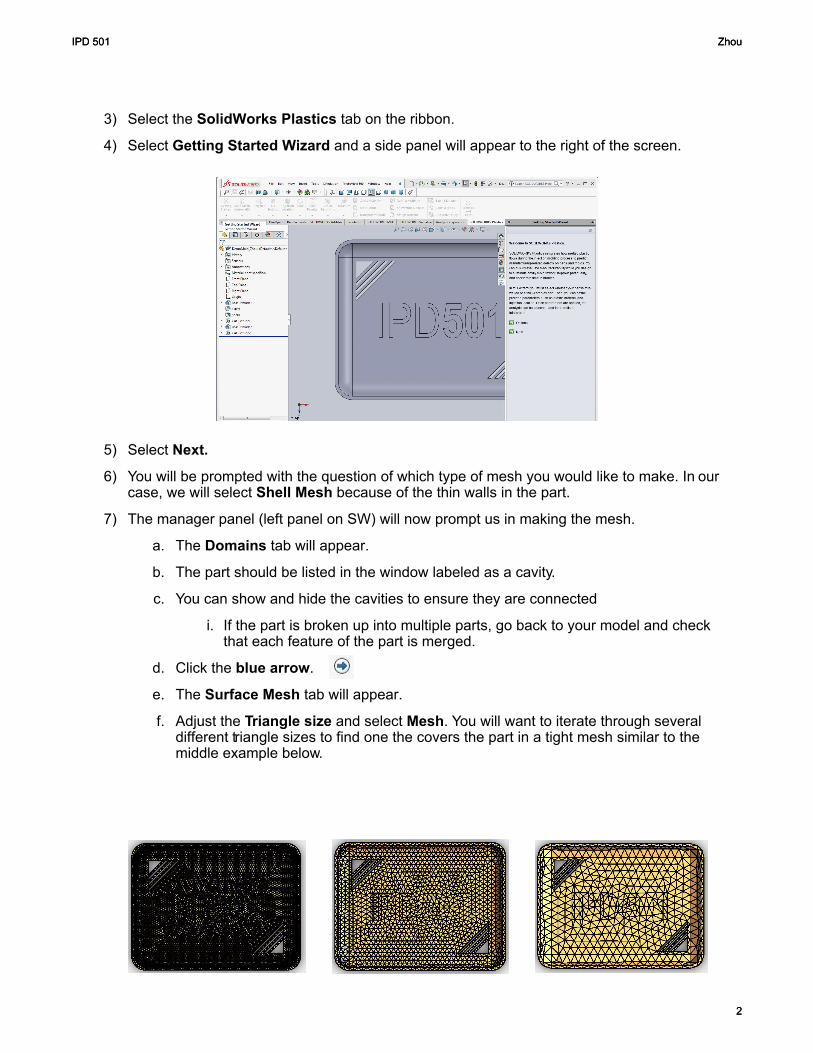
3) Select the SolidWorks Plastics tab on the ribbon.
4) Select Getting Started Wizard and a side panel will appear to the right of the screen.
5) Select Next.
6) You will be prompted with the question of which type of mesh you would like to make. In ourcase, we will select Shell Mesh because of the thin walls in the part.
7) The manager panel (left panel on SW) will now prompt us in making the mesh.
a. The Domains tab will appear.
b. The part should be listed in the window labeled as a cavity.
c. You can show and hide the cavities to ensure they are connected
i. If the part is broken up into multiple parts, go back to your model and checkthat each feature of the part is merged.
d. Click the blue arrow.
e. The Surface Mesh tab will appear.
f. Adjust the Triangle size and select Mesh. You will want to iterate through severaldifferent triangle sizes to find one the covers the part in a tight mesh similar to themiddle example below.
IPD 501 Zhou
2
IPD 501 Zhou
2
i. Click the blue arrow.
j. Summary window will appear providing feedback on the mesh.For a good part the aim would be to keep intersections andnon-manifolds at zero.
k. Click the green check.
l. Click the green check again.
8) Move back to the Wizard panel (right panel in SW) and select Next.
9) The Material tab will open.
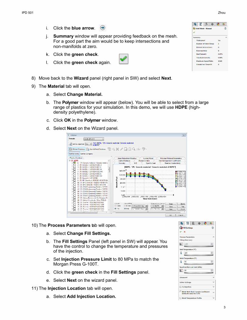
a. Select Change Material.
b. The Polymer window will appear (below). You will be able to select from a largerange of plastics for your simulation. In this demo, we will use HDPE (high-density polyethylene).
c. Click OK in the Polymer window.
d. Select Next on the Wizard panel.
10) The Process Parameters tab will open.
a. Select Change Fill Settings.
b. The Fill Settings Panel (left panel in SW) will appear. Youhave the control to change the temperature and pressuresof the injection.
c. Set Injection Pressure Limit to 80 MPa to match theMorgan Press G-100T.
d. Click the green check in the Fill Settings panel.
e. Select Next on the wizard panel.
11) The Injection Location tab will open.
a. Select Add Injection Location.
IPD 501 Zhou
3
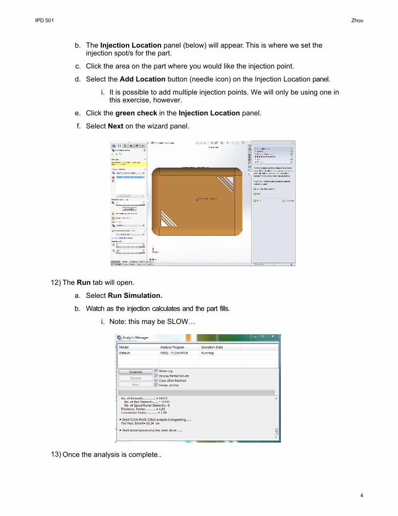
b. The Injection Location panel (below) will appear. This is where we set theinjection spot/s for the part.
c. Click the area on the part where you would like the injection point.
d. Select the Add Location button (needle icon) on the Injection Location panel.
i. It is possible to add multiple injection points. We will only be using one inthis exercise, however.
e. Click the green check in the Injection Location panel.
f. Select Next on the wizard panel.
12) The Run tab will open.
a. Select Run Simulation.
b. Watch as the injection calculates and the part fills.
i. Note: this may be SLOW…
13) Once the analysis is complete..
IPD 501 Zhou
4
a. Click the play button on the Results panel (Left Panel in SW)and watch the fill simulation from multiple angles and look atthe different feature.
b. The Results Advisor Window (left) also provide feedback onthe part and some explanation to help read your results.
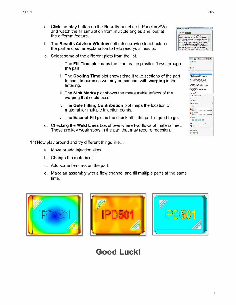
c. Select some of the different plots from the list.
i. The Fill Time plot maps the time as the plastics flows through the part.
ii. The Cooling Time plot shows time it take sections of the part to cool. In our case we may be concern with warping in the lettering.
iii. The Sink Marks plot shows the measurable effects of the warping that could occur.
iv. The Gate Filling Contribution plot maps the location of material for multiple injection points.
v. The Ease of Fill plot is the check off if the part is good to go.
d. Checking the Weld Lines box shows where two flows of material met. These are key weak spots in the part that may require redesign.
14) Now play around and try different things like…
a. Move or add injection sites.
b. Change the materials.
c. Add some features on the part.
d. Make an assembly with a flow channel and fill multiple parts at the same time.
Good Luck!
IPD 501 Zhou
5