Embed Size (px)
Citation preview
1
IPA™2300 Power AmpliferOwner’s Manual
2
IPA™ 2300Power AmplifierThe IPA™ 2300 is a high-quality‚ industrial-grade audio amplifier. Designed for flexibility in application‚ this amplifier represents the latest‚ state-of-the-art technology in amplifier design. Powerful‚ yet easy to use‚ the new IPA series delivers amazing sonic performance. Low-noise design and features applicable to “real world” situations make these units ideal for audio applications where a powerful, yet compact amplifier with multiple input and output capabilities are required.
We feel that the best way to fully enjoy any purchase is to have an in-depth understanding of the product’s features‚ functionality and performance characteristics. We hope this manual‚ along with the manuals of our other products‚ will provide this. If you require additional information not provided in this manual‚ please let us know or check out our website at:
Web site: http://peaveycommercialaudio.com/products.cfm/cr/:
Email: [email protected]
We are continuously looking for better ways to provide information about our products and your input is always appreciated.
ENGLISH
IPA™ 2300 Features:• Efficient 300 Watt class-D power amplifier • Electronically balanced line/mic input • Unbalanced line input with Dual-RCA summing connectors for Auxiliary sources• Channel 1 Priority/Muting system with variable threshold • External switch input for “Mute All” control• Amplifier signal indicator• ACL ™ (Automatic Clip Limiting) circuitry with indicator• 4 Ohm direct output• 25 Volt, 70 Volt, and 100 Volt outputs• Power ON indicator• Line Voltage Selector switch for 100-120 VAC or 220-240 VAC 50/60 Hz operation• Optional rack mounting with included rack ears
Applications:
• Presentation rooms• Board rooms• Courtrooms• Auditoriums• Lecture halls• Meeting rooms• Convention centers• Paging systems• Background music• Retail spaces• Restaurants
3
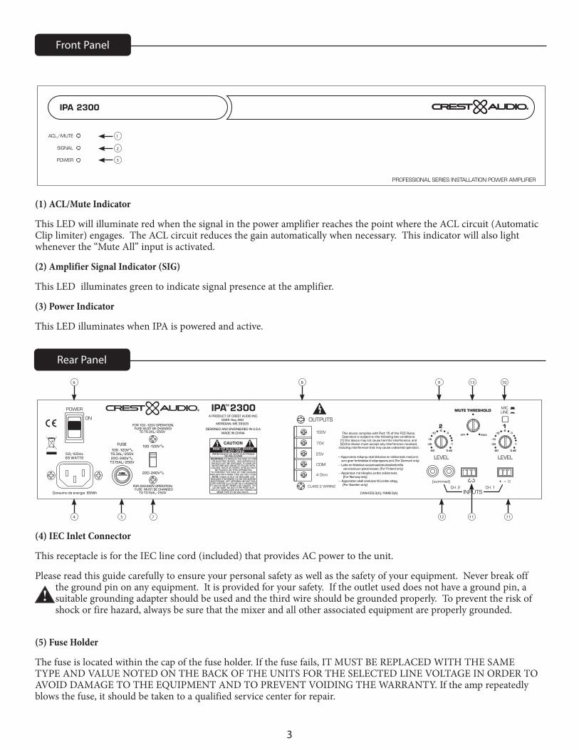
(1) ACL/Mute Indicator
This LED will illuminate red when the signal in the power amplifier reaches the point where the ACL circuit (Automatic Clip limiter) engages. The ACL circuit reduces the gain automatically when necessary. This indicator will also light whenever the “Mute All” input is activated.
(2) Amplifier Signal Indicator (SIG)
This LED illuminates green to indicate signal presence at the amplifier.
(3) Power Indicator
This LED illuminates when IPA is powered and active.
Front Panel
IPA 2300
POWER
SIGNAL
ACL/MUTE
PROFESSIONAL SERIES INSTALLATION POWER AMPLIFIER
TM
1
6
4 5 7 12 1111
8 9 13 10
2
3
Rear Panel
LEVEL
CH. 2
(summed)
CH. 1
MICLINE
INPUTS
MUTE THRESHOLD
OFF MAX
1
-80 0 dB
-1
-3-6
-10
-15
-30
LEVEL
2
-80 0 dB
-1
-3-6
-10
-15
-30
POWER
ON
50/60Hz65 WATTS
Consumo de energia 65Wh
MADE IN CHINADESIGNED AND ENGINEERED IN U.S.A.
A PRODUCT OF CREST AUDIO INC.5022 Hwy 493
MERIDIAN, MS 39305
100 -120V
220-240V
FUSE100 -120VT6.3AL/250V220-240V
T3.15AL/250V
FUSE MUST BE CHANGED FOR 100 -120V OPERATION,
TO T6.3AL/250V
FUSE MUST BE CHANGEDFOR 220-240V OPERATION,
TO T3.15AL/250V
CLASS 2 WIRING
OUTPUTS
CAN-ICES-3(A)/NMB-3(A)
- - Apparatet må tilkoples jordet stikkontakt. (For Norway only)- - Apparaten skall anslutas till jordat uttag. (For Sweden only)
- - Laite on liitettävä suojamaadoituskoskettimilla varustettuun pistorasiaan. (For Finland only)
CAUTION
WARNING:OR ELECTRIC SHOCK, THIS APPARATUS
LIQUIDS, SUCH AS VASES, SHOULD NOT
SHOULD NOT BE EXPOSED TO RAIN ORMOISTURE AND OBJECTS FILLED WITH
TO PREVENT THE RISK OF FIRE HAZARD,BE PLACED ON THIS APPARATUS.
REPLACE WITH SAME TYPE 250 VOLT FUSE.
TO REDUCE THE RISK OF FIRE
DANS LE BUT DE REDUIRE LES AVIS:ELECTRIQUE, CET APPAREIL NE DOIT PASRISQUES D’INCENDIE OU DE DECHARGE
ETRE EXPOSE A LA PLUIE OU A L’HUMIDITEET AUCUN OBJET REMPLI DE LIQUIDE, TEL
QU’UN VASE, NE DOIT ETRE POSE SUR CELUI-CI. REMPLACER PAR UN FUSIBLE DE
MEME TYPE ET DE 250 VOLTS.
AVIS:RISQUE DE CHOC ELECTRIQUENE PAS OUVRIR
This device complies with Part 15 of the FCC Rules.
including interference that may cause undesired operation. (2) this device must accept any interference received, (1) this device may not cause harmful interference, and
Operation is subject to the following two conditions:
25V
4 Ohm
100V
IPA 2300TM
COM
70V
- - Apparatets stikprop skal tilsluttes en stikkontakt med jord, som giver forbindelse til stkproppens jord. (For Denmark only)
+ _ G
MUTE ALL
FUSEFUSE
(4) IEC Inlet Connector
This receptacle is for the IEC line cord (included) that provides AC power to the unit.
Please read this guide carefully to ensure your personal safety as well as the safety of your equipment. Never break off the ground pin on any equipment. It is provided for your safety. If the outlet used does not have a ground pin, a suitable grounding adapter should be used and the third wire should be grounded properly. To prevent the risk of shock or fire hazard, always be sure that the mixer and all other associated equipment are properly grounded.
(5) Fuse Holder
The fuse is located within the cap of the fuse holder. If the fuse fails, IT MUST BE REPLACED WITH THE SAME TYPE AND VALUE NOTED ON THE BACK OF THE UNITS FOR THE SELECTED LINE VOLTAGE IN ORDER TO AVOID DAMAGE TO THE EQUIPMENT AND TO PREVENT VOIDING THE WARRANTY. If the amp repeatedly blows the fuse, it should be taken to a qualified service center for repair.
4
WARNING: The fuse should only be replaced when the power cord has been disconnected from its power source!
(6) Power Switch
This rocker switch applies mains power to the unit.
(7) Line Voltage Selector Switch
The line voltage select should be checked and set to match the mains voltage before connecting and operating this unit. The UMA 4300 can be operated at 100V-120 VAC or 220-240 VAC 50/60 Hz.
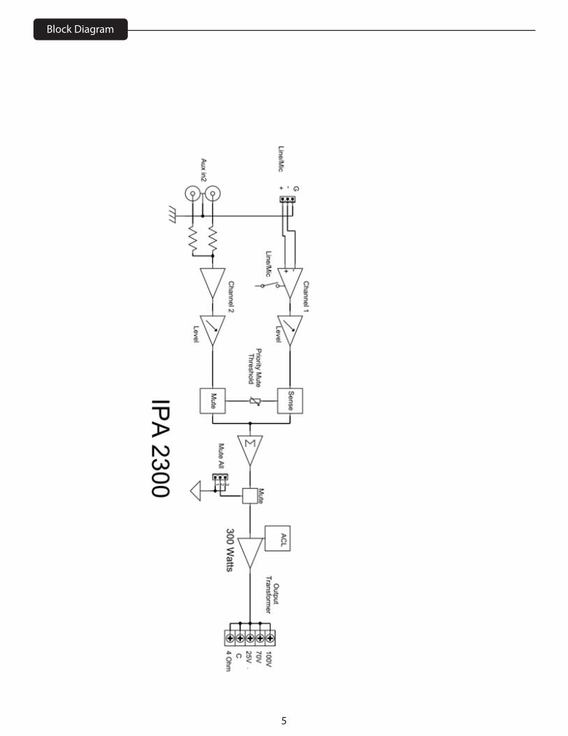
(8) Outputs
A direct output and transformer outputs are provided to allow proper interface between the amplifier and the loudspeaker system. Connect the loudspeaker system to the appropriate output connector and the COM terminal. Connections for 4 Ohm, 25 Volt, 70 Volt and 100 Volt systems are available.
(9) Input Channel Level Controls
These rotary controls set the channel signal level sent to the mix bus. Adjust this control for the desired output volume.
(10) Line/Mic Switch
This switch configures the channel gain and input impedance of channel 1 for microphone or line level applications. Press in for line level input sources.
(11) Balanced Input Connector (Input 1)
The electronically-balanced input will accept both line and mic level signals as set by the line/mic switch.
(12) Dual RCA Input Connectors (Input 2)
The dual RCA input connectors provide an easy way to connect a mono or stereo, unbalanced source to the IPA 2300.
(13) Threshold Control
Channel 1 can be the controlling channel of the priority mute system. When the signal level on channel 1 exceeds the threshold set by the threshold control, channel 2 is muted. Setting this control at the full counter-clockwise position defeats the muting function.
(14) Mute All
Connecting the two terminals on the mute all input connector, mutes all audio through the IPA 2300. This may need to be connected to a fire alarm system, for example, to mute audio in case of emergency. The ACL light on the front panel will light when this mute is activated
NOTE: For rack mount installations, use 4 machine screws through the front panel mounting holes to secure the amplifier to the rack rails.
5
Block Diagram
6
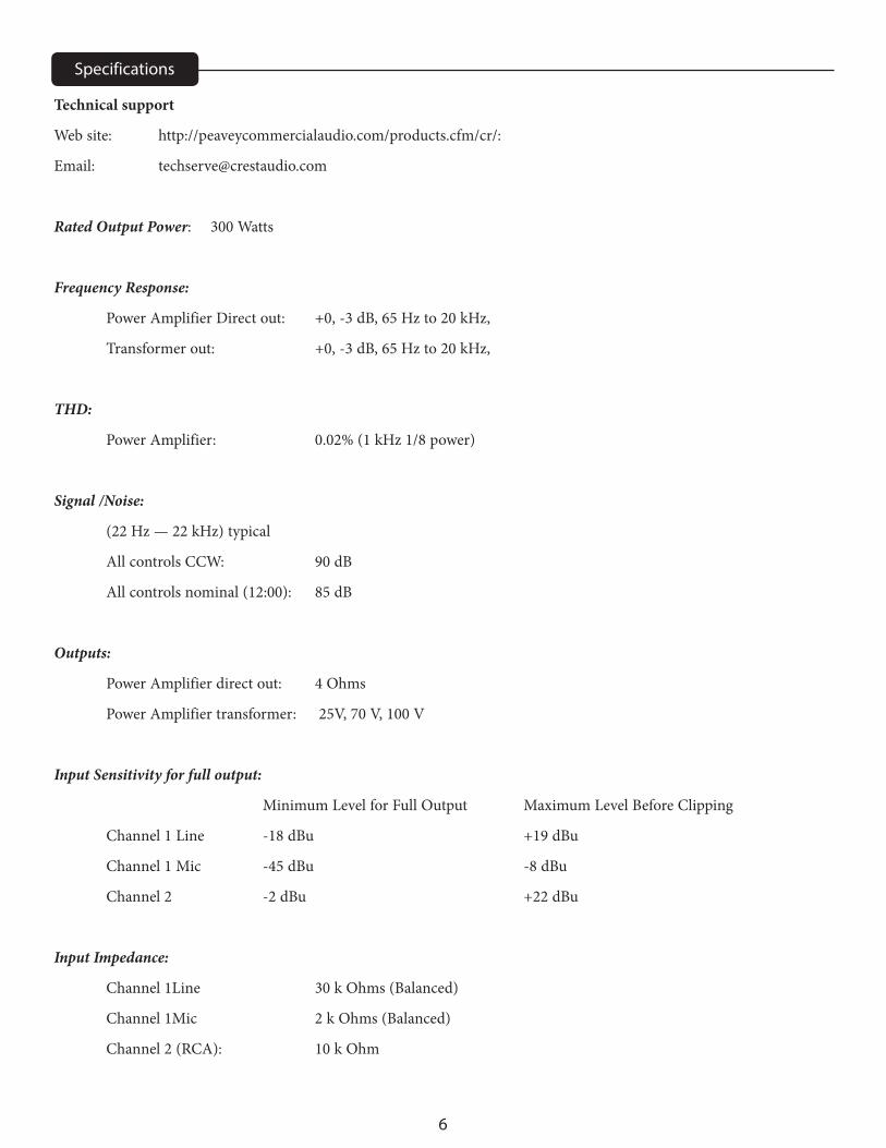
Technical support
Web site: http://peaveycommercialaudio.com/products.cfm/cr/:
Email: [email protected]
Rated Output Power: 300 Watts
Frequency Response:
Power Amplifier Direct out: +0, -3 dB, 65 Hz to 20 kHz,
Transformer out: +0, -3 dB, 65 Hz to 20 kHz,
THD:
Power Amplifier: 0.02% (1 kHz 1/8 power)
Signal /Noise:
(22 Hz — 22 kHz) typical
All controls CCW: 90 dB
All controls nominal (12:00): 85 dB
Outputs:
Power Amplifier direct out: 4 Ohms
Power Amplifier transformer: 25V, 70 V, 100 V
Input Sensitivity for full output:
Minimum Level for Full Output Maximum Level Before Clipping
Channel 1 Line -18 dBu +19 dBu
Channel 1 Mic -45 dBu -8 dBu
Channel 2 -2 dBu +22 dBu
Input Impedance:
Channel 1Line 30 k Ohms (Balanced)
Channel 1Mic 2 k Ohms (Balanced)
Channel 2 (RCA): 10 k Ohm
Specifications
7
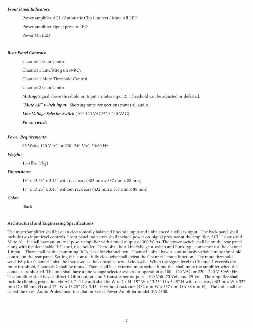
Front Panel Indicators:
Power amplifier ACL (Automatic Clip Limiter) / Mute All LED
Power amplifier Signal present LED
Power On LED
Rear Panel Controls:
Channel 1 Gain Control
Channel 1 Line/Mic gain switch
Channel 1 Mute Threshold Control
Channel 2 Gain Control
Muting: Signal above threshold on Input 1 mutes input 2. Threshold can be adjusted or defeated.
“Mute All” switch input. Shorting mute connections mutes all audio.
Line Voltage Selector Switch (100-120 VAC/220-240 VAC)
Power switch
Power Requirements:
65 Watts, 120 V AC or 220 -240 VAC 50/60 Hz
Weight:
15.4 lbs. (7kg)
Dimensions:
19” x 13.25” x 3.45” with rack ears (483 mm x 337 mm x 88 mm)
17” x 13.25” x 3.45” without rack ears (432 mm x 337 mm x 88 mm)
Color:
Black
Architectural and Engineering Specifications
The mixer/amplifier shall have an electronically balanced line/mic input and unbalanced auxiliary input. The back panel shall include two input level controls. Front panel indicators shall include power on, signal presence at the amplifier, ACL ™ status and Mute All. It shall have an internal power amplifier with a rated output of 300 Watts. The power switch shall be on the rear panel along with the detachable IEC cord, fuse holder. There shall be a Line/Mic gain switch and Euro-type connector for the channel 1 input. There shall be dual summing RCA jacks for channel two. Channel 1 shall have a continuously variable mute threshold control on the rear panel. Setting this control fully clockwise shall defeat the Channel 1 mute function. The mute threshold sensitivity for Channel 1 shall be increased as the control is turned clockwise. When the signal level in Channel 1 exceeds the mute threshold, Channels 2 shall be muted. There shall be a external mute switch input that shall mute the amplifier when the contacts are shorted. The unit shall have a line voltage selector switch for operation at 100 - 120 VAC or 220 - 240 V 50/60 Hz. The amplifier shall have a direct 4 Ohm output, and 3 transformer outputs – 100 Volt, 70 Volt, and 25 Volt. The amplifier shall include clipping protection via ACL ™ . The unit shall be W x D x H 19” W x 13.25” D x 3.45” H with rack ears (483 mm W x 337 mm D x 88 mm H) and 17” W x 13.25” D x 3.45” H without rack ears (432 mm W x 337 mm D x 88 mm H). The unit shall be called the Crest Audio Professional Installation Series Power Amplifier model IPA 2300.
8
Logo referenced in Directive 2002/96/EC Annex IV(OJ(L)37/38,13.02.03 and defined in EN 50419: 2005The bar is the symbol for marking of new waste and
is applied only to equipment manufactured after13 August 2005
www.peaveycommercialaudio.comWarranty registration and information for U.S. customers available online at
www.peaveycommercialaudio.com/warrantyor use the QR tag below
Features and speci�cations subject to change without notice.
Crest Audio 5022 HWY 493 N. Meridian, MS 39305 (601) 483-5365 FAX (601) 486-1278


![[XLS] - Mar15/District Reasi new proforma... · Web view2035 2300 2036 2300 2037 2300 2038 2300 2039 2300 2040 2300 2041 2300 2042 2300 2043 2300 2044 2300 2045 2300 2046 2300 2047](https://img.pdfslide.us/doc/110x75/5aa68dbc7f8b9a517d8ea409/xls-mar15district-reasi-new-proformaweb-view2035-2300-2036-2300-2037-2300.jpg)