Embed Size (px)
Citation preview

Maritime Stress
PO Box 2898, 30 Estates Road Dartmouth, NS, B2W 4Y2, Canada
Toll Free: 1-877-468-1781 Phone: (902) 468-7873 Fax: (902) 468-2304
Website: www.maritimestress.com E-mail: [email protected]
OPERATION MANUAL
IP2008-6-HW FULLY AUTOMATIC HEAT TREATMENT CONSOLE

IP2008-6-HW Fully Automatic Heat Treatment Console REV 0, 04/05
www.maritimestress.com
2
INDEX
IP2008-6-HW FULLY AUTOMATIC HEAT TREATMENT CONSOLE
IP2008-6-HW FULLY AUTOMATIC HEAT TREATMENT CONSOLE Description, Page 3 Specifications – IP2008-6-HW Fully Automatic Heat Treatment Console, Page 3 & 4 Maintenance Requirements, Page 5 IP2008-6-HW Operating Instructions, Page 6, 7, 8 & 9 IP2008-6-HW Operating Instructions, Page 6, 7, 8 & 9 IP2008-6-HW Complete Parameter Programming, Page 10, 11, & 12 IP2008-6-HW Fully Automatic 6 Way Heat Treatment Console System Connections, Page 13 To change secondary and primary connections follows these instructions, Page 14 Spare parts IP2008-6-HW Fully Automatic 6 Way Heat Treatment Console, Page 15

IP2008-6-HW Fully Automatic Heat Treatment Console REV 0, 04/05
www.maritimestress.com
3
IP2008-6-HW Fully Automatic Six Way Heat Treatment Console: DESCRIPTION: The IP2008-6-HW Fully Automatic heat treatment console is designed to control various heat treatment processes by closely monitoring and adjusting the set point temperature and the ramp rate. It incorporates the latest microprocessor based technology and is simple to set up and operate. Control setting is by means of push switches and an LCD screen provides visual indication of the set point and the actual temperature. The IP2008-6-HW is equipped with a digital amp meter and a 6 position switch, which is the utmost importance for checking the current to the ceramic pad heaters to make sure they are all operating.
SPECIFICATIONS – IP2008-6-HW Fully Automatic Six Way Heat Treatment Console: Length: 33” Width: 27” Height: 44” to the top of the lifting lug Weight: Approx. 940lbs Material: 12 gauge stainless steel cabinet Wheels: 900 lbs capacity each with brake (4) (or SS mounting brackets available upon request) Handling: Two heavy duty top lifting eye lugs and forklift access. Inputs:
Voltage: 380-415-440-480-575, 3 Phase Current: 100 amp or optional 125 amps for 380/415 VAC Power: 75 KVA Isolated Copper Wound Frequency: 60 Hz / 50 Hz
Output Per Zone:
Zones: 6 Voltage: 65 or 85 VAC, single phase Current: 192 amps @ 65 V or 156 amps 85V Power: 12.5 KVA Activation: 200 amp contactor Control per zone: Digital temperature controller
Control Circuit:
Voltage: 110 VAC, single phase Current: 5 amp circuit breaker Power: 1.2 KVA winding on power transformer Auxiliary: 110 VAC supply, single phase

IP2008-6-HW Fully Automatic Heat Treatment Console REV 0, 04/05
www.maritimestress.com
4 Digital Temperature Controller (UDC2500):
Temperature Range: 0-2200°F Thermocouple: Type “K”
Digital Amp Meter:
Primary Amperage: Up to 200 amps Secondary Amperage: 5 amps
Protection:
120-VAC Control Circuit: 5 amp circuit breaker Heater Power: Isolation contactor for each zone Console Power: 100 amp main circuit breaker Power Transformer: 392°F (200°C) over temperature thermostat per phase Cooling fan: 340 CFM - Thermally protected

IP2008-6-HW Fully Automatic Heat Treatment Console REV 0, 04/05
www.maritimestress.com
5 \
Maintenance Requirements:
Inspection and Cleaning:
ITEM INSPECTION FREQUENCY ACTION Contactors Burned or Pitted Every 6 months Clean or replace contacts Temperature Controllers Calibration Every 12 months Check accuracy and adjust
if required System Cleanliness Every 6 months Vacuum with power
disconnected System Electrical Loose connections Every 6 months Tighten all terminal
connections Air Vents and fan Dust or dirt build up Every 3 months Clean with vacuum with
power disconnected Check bolts and screws Loose Every 6 months Tighten

IP2008-6-HW Fully Automatic Heat Treatment Console REV 0, 04/05
www.maritimestress.com
6
IP20085-6-HW Fully Automatic Six Way Heat Treatment Console Operating Instructions:
1. Switch 100 amp main circuit breaker to the “ON” position. 2. Make sure zones used are indicating the actual temperature on the controllers prior to start and then turn
rocker switches to the “ON” position. 3. Decide on the heat treatment specification and set as follows:
HONEYWELL UDC 2500 Programming a Heat Cycle
1. Turn switch on to power on controller Upper Display: (T.C. TEMP) • controller will run a self test, when completed it will read: Lower Display: OUT 0.0
2. Press SETUP button until you see: Upper Display: SET Lower Display: SP RAMP 3. Press FUNCTION button until you see: Upper Display: ENAB
(adjust Upper Display to ENABLE if required) Lower Display: SP PROG NOTE: This function must be set correct to continue programming and must be RE-SET to ENAB before every heat cycle in which the controller entirely completes it’s program (if the controller is shut off before entirely completing the program SP PROGRAM will remain as ENAB). If SP RATE or SP RAMP appear in the Lower Display in this step the Upper Display must be set to DIS for both.
Use the FUNCTION button to advance through the remaining programming steps. Use the ARROW buttons to change any Upper Display readouts. LOWER UPPER
STEP DISPLAY DISPLAY SEGMENT COMMENTS
4 STR SEG 1 Stage at which heat cycle will start 5 END SEG SOK 6 # of stages required (standard c.s. heat cycle = 6) 6 RPUNIT EU/HR Degrees per hour 7 RECYCL 0 Has to be set at “0” or heat cycle will re-start 8 SOK DEV 10.00 Deviation must be set or soak time would start even
if weld temps were not at soak temp. 9 P END F SAF Program will end on last segment set point (seg – 6)
10 STATE DISABL Disabled to shut down heat cycle at last segment 11 ToBEGIN
or KEYRESET
DIS
Which Lower Display appears in this step is dependent on the manufacturers configurations, ensure the Upper Display is set to “ DISABL” regardless of Lower Display read-out
12 PV START DIS (doesn’t appear in all controllers) 13 SG1RP degrees/hr 1 Ramp rate to SEG 2 set point (e.g. 450/hr) 14 SG2 SP TEMP 2 Target temperature (e.g. 310 or 420)

IP2008-6-HW Fully Automatic Heat Treatment Console REV 0, 04/05
www.maritimestress.com
7 15 SG2TI SOAK TIME 2 0.0 soak time at this stage on standard heat cycles 16 SG3RP degrees/hr 3 Ramp rate to SEG 4 set point (e.g. 220/hr) 17 SG4 SP TEMP 4 Target temperature (e.g. 621) 18 SG4TI SOAK TIME 4 (e.g. 1.00 hr) 19 SG5RP degrees/hr 5 Ramp rate to SEG 6 set point (e.g. 275/hr) 20 SG6 SP TEMP 6 Target temperature (e.g. 310 or 420) 21 SG6TI SOAK TIME 6 0.0 soak time at this stage on standard heat cycles
NOTE: Your Heat Cycle will now stop at the end of this segment as #6 END SEG was chosen at the beginning of the set up. The remaining stages need not to be programmed, as they will not be used on a standard Heat Cycle. Press the LOWER DISPLAY button to exit programming, press the AUTO/MANUAL button to put controller to AUTO, you can now adjust your initial set points as required (controller must be in HOLD & AUTO), press the RUN/HOLD button to run program you have entered.

IP2008-6-HW Fully Automatic Heat Treatment Console REV 0, 04/05
www.maritimestress.com
8 HONEYWELL UDC 2500
Operating procedures
General Rules: 1. The controller must be in AUTO mode and on HOLD before you can make any changes to a
program you have started running.
2. Once the controller has been put into AUTO mode (whether that is at initial start up of a program or after changes have been made to a running program), the set point (SP) is automatically set to the actual thermocouple reading. The controller will call for power output to hold this temperature unless it is adjusted or the program is started. To adjust the set point, put the controller in AUTO & HOLD, use the DISPLAY button to display the set point “SP” and use the ARROW buttons to increase or decrease set point as required.
3. To use the ARROW buttons effectively follow these instructions: • Press and hold the “up” ARROW button and the number will start to climb by the lowest denomination
slowly and increase in speed and denomination with time held. • While holding the “up” ARROW button, press and release the “down” ARROW button and this will move
the number increasing from “1’s” to “10’s” to “100’s” and so on. 4. Pressing the LOWER DISPLAY button while running will display the following:
• SP “TEMP” (set point temperature) • OU “50%” (output power in percentage) • DE “-10” (actual temp is 10 degrees below set point) • “3 220 or 4 1.00” (ramp or soak stage that program is in) – time will only be shown in soak stage
Adjusting Ramp rates & Target/Soak temperatures (eg. 310/420 or 621/732): Ramp rates can be adjusted at any time during the heat cycle and will take effect immediately. You can not adjust your first target temp (eg. 310/425) after you have started running the heat cycle. You must turn the controller off and on again and adjust SEG2 SP (310/420) as required. You can adjust your soak temp (eg. 621/732) if your heat cycle program is still in the first stage (SEG1RAMP 450/HR). You can not however change your soak temp if your heat cycle program is in SEG3RAMP 220/HR. In this case you would have to turn controller off and on again and adjust SEG4 SP as required (changing stages procedure may have to be followed as well). Note: If you adjust your target/soak temp “out of proper sequence”, the controller will run weld up to initially programmed target/soak temp and then automatically adjust to new target/soak temp and wait for actual temp to free fall or climb without any “rate” control.
IP2008-6-HW Fully Automatic Heat Treatment Console REV 0, 04/05
www.maritimestress.com
9
HONEYWELL UDC 2500
Operating procedures (continued)
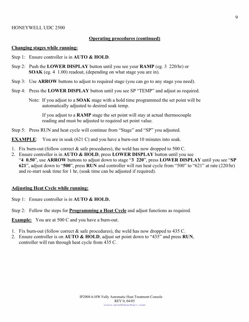
Changing stages while running: Step 1: Ensure controller is in AUTO & HOLD. Step 2: Push the LOWER DISPLAY button until you see your RAMP (eg. 3 220/hr) or SOAK (eg. 4 1.00) readout, (depending on what stage you are in). Step 3: Use ARROW buttons to adjust to required stage (you can go to any stage you need). Step 4: Press the LOWER DISPLAY button until you see SP “TEMP” and adjust as required. Note: If you adjust to a SOAK stage with a hold time programmed the set point will be automatically adjusted to desired soak temp. If you adjust to a RAMP stage the set point will stay at actual thermocouple reading and must be adjusted to required set point value. Step 5: Press RUN and heat cycle will continue from “Stage” and “SP” you adjusted. EXAMPLE: You are in soak (621 C) and you have a burn-out 10 minutes into soak. 1. Fix burn-out (follow correct & safe procedures), the weld has now dropped to 500 C. 2. Ensure controller is in AUTO & HOLD, press LOWER DISPLAY button until you see
“4 0.50”, use ARROW buttons to adjust down to stage “3 220”, press LOWER DISPLAY until you see “SP 621”, adjust down to “500”, press RUN and controller will run heat cycle from “500” to “621” at rate (220/hr) and re-start soak time for 1 hr, (soak time can be adjusted if required).
Adjusting Heat Cycle while running: Step 1: Ensure controller is in AUTO & HOLD. Step 2: Follow the steps for Programming a Heat Cycle and adjust functions as required. Example: You are at 500 C and you have a burn-out. 1. Fix burn-out (follow correct & safe procedures), the weld has now dropped to 435 C. 2. Ensure controller is on AUTO & HOLD, adjust set point down to “435” and press RUN,
controller will run through heat cycle from 435 C.

IP2008-6-HW Fully Automatic Heat Treatment Console REV 0, 04/05
www.maritimestress.com
10 HONEYWELL UDC 2500
(USE FOR INITIAL SET UP OF CONTROLLERS ONLY) FOR SERVICE DEPARTMENT ONLY
Complete Parameter Programming
1. Turn controller power on. Upper Display: (T.C. TEMP) • controller will run a self test, when completed it will read: Lower Display: OT 0.0
Press the SETUP button to advance to “parameter groups” (eg. TUNING, SP RAMP, etc.). Press the FUNCTION button to program the selected “parameter group” settings. Press the ARROW buttons to change any UPPER DISPLAY readouts. Follow instructions in “COMMENTS” column as required. NOTE: The first two “parameter groups”, (INPUT 1, CONTROL) have to be programmed in order. The remaining “parameter groups” must to be programmed after the first two are completed.
PARAMETER LOWER UPPER GROUP DISPLAY DISPLAY COMMENTS
INPUT 1 INPUT 1 SET IN1TYP K H IN1 HI 1316 IN1 LO - 17.8 RATIO1 1.0 BIAS1 0.0 FILTR1 20 BRNOUT NONE
There are two “INPUT 1” parameter groups, ensure you are at this “SETUP” group to avoid confusion. The other “INPUT 1” parameter group does not show up during initial programming.
CONTRL CONTRL SET PIDSET ONE LSP’S ONE SP TRK PROC PWR UP MAN SP Hi 1316 SP Lo -17.8 ACTION REV OUT Hi 100 OUT Lo 0.0 FAILSF 0.0 FSMODE NO L PBorGN PB MINRPM MIN
COM COM SET ComADR 3 ComSTA DIS IRENAB ENAB BAUD 19.2K TX DLY 1

IP2008-6-HW Fully Automatic Heat Treatment Console REV 0, 04/05
www.maritimestress.com
11
HONEYWELL UDC 2500
Complete Parameter Programming (continued)
PARAMETER LOWER UPPER GROUP DISPLAY DISPLAY COMMENTS
ALARMS ALARMS
SET
A1S1TY IN 1 A1S1VA 1300 This function does not show up until the rest
of the “ALARM” functions are programmed A1S1 H L HIGH A1S2TY NONE A2S1TY NONE A2S2TY NONE ALHYST 5.0 ALARM1 NO L BLOCK DIS Go back and set A1S1 VAL after this step DIA AL DIS
DISPLAY DISPLAY SET Program this
parameter first DECIMAL NONE
T UNITS C FREQ 60 NOLDSP DIS LNGUAG ENGL
INPUT 1 INPUT 1 CAL There are 2 INPUT 1 groups, ensure you are in the correct group setting.
CALIN 1 DIS
STATUS STATUS READ Read Only (Important to cycle thru steps)
TUNING TUNING SET PB 2.50 RATE T 1.04 I MIN 4.16 CYCT1 5 SECURITY Don’t set anything LOCKOUT VIEW AUTOMA ENAB A TUNE ENAB RN HLD ENAB SP SEL ENAB

IP2008-6-HW Fully Automatic Heat Treatment Console REV 0, 04/05
www.maritimestress.com
12
HONEYWELL UDC 2500
Complete Parameter Programming (continued)
PARAMETER LOWER UPPER GROUP DISPLAY DISPLAY COMMENTS
SP RAMP SP RAMP SET REFER TO PROGRAMMING HEAT CYCLES
ATUNE ATUNE SET FUZZY ENAB TUNE DIS
ALGOR ALGOR SET CTRALG PID A TIMER DIS
OUTALG OUTALG SET OUTALG RLY RLY TYP MECH

IP2008-6-HW Fully Automatic Heat Treatment Console REV 0, 04/05
www.maritimestress.com
13
FRONT VIEW
CP10
CP10 CP10
Note: The IP2008-6-HW connections for circuit number 6 shown. Circuit numbers 1, 2, 3, 4, & 5 should be connected in the same manner
Parallel connection of heaters
Thermocouple Cable
Thermocouple Wire
3 way splitter 3 way splitter
Secondary Cable
IP2008-6-HW Fully Automatic 6 Way Heat Treatment Console System Connections:
6
5
4
3
2
1

IP2008-6-HW Fully Automatic Heat Treatment Console REV 0, 04/05
www.maritimestress.com
14
TO CHANGE SECONDARY AND PRIMARY CONNECTIONS FOLLOWS THESE INSTRUCTIONS: 1. Switch off main breaker and disconnect primary power cable supply. 2. Loosen the primary power cable clamp. 3. Remove panel labelled “Back Panel” to change secondary and primary connections. 4. Change connections as per requirements and make sure the connections are tight. 5. Make sure nothing is left inside the enclosure. 6. Put the “Back Panel” back on. 7. Tighten the primary power cable clamp. 8. Hook up primary power cable supply and then switch on main breaker when ready.
• 75 KVA/60 KW • Primary 380/415/440/480/575, 3 Phase
• Secondary 0/65/85, Single Phase
• (1 P.H.) 110 volt @ 1200 VA, Single
Phase
• Isolation
• Copper wound • Over temperature thermostat per phase
Transformer:
Weight: 660 lbs (approx.) Dimensions: 24” L x 17” W x 21” H Features:
• All connections in back for easy access. • Class 220 insulation. • 150 degrees C. temperature rise. • CSA certified. • UL listed. • Manufactured to ISO9001 quality certification.
ORDERING INFORMATION:
MSPART# - 75KVA #7 - 3 phase isolated copper wound power transformer. Primary 380/415/440/480/575, 50/60 Hz secondary 0/65/85 (Thermal trips per phase to prevent overload).
CHANGING TAPPINGS:
PRIMARY VOLTAGE
CURRENT 18 x 80V Heaters
CONNECTION
575 VAC 76 amps 1-1-1 480 VAC 91 amps 2-2-2 440 VAC 99 amps 3-3-3 415 VAC 105 amps 4-4-4 380 VAC 114 amps 5-5-5
SECONDARY
VOLTAGE CURRENT CONNECTION
65 volts 384 amps per phase
65-65-65 as marked
85 volts 312 amps per phase
85-85-85 as marked
**NOTE: Optional 125 amp circuit breaker required for 380VAC/415 Primary Voltage
575 VAC 575 VAC 575 VAC
480 VAC 480 VAC 480 VAC
440 VAC 440 VAC 440 VAC
415 VAC 415 VAC 415 VAC
380 VAC 380 VAC 380 VAC
65 VAC
85 VAC
0 VAC 0 VAC 0 VAC
65 VAC 65 VAC
85 VAC 85 VAC

IP2008-6-HW Fully Automatic Heat Treatment Console REV 0, 04/05
www.maritimestress.com
15 SPARE PARTS FOR IP2008-6-HW HEAT TREATMENT CONSOLE
MS Part No. Description Of Part
IP2008-6-HW Stainless Steel Cabinet for IP2008-6-HW
900Wheel Wheel Swivel Caster (900 lb Capacity with brake)
UDC2500 Fully Automatic Digital Temperature Controller
75KVA #7 75 KVA - 3 Phase Isolated copper wound power transformer: Primary 380/415/440/480/575, 50/60 Hz Secondary 0/65/85 (Thermal trips per phase to prevent
overload) Amp Meter Digital Amp Meter 0-200 amps
Selector Switch Six Channel Selector Switch with Plate & Knob
CT Current Transformer 0-200 amps
A10 300 amp Female Panel Mount Socket Complete
PP-20-KX Thermocouple Extension Cable
A37-EL 200 amp contactor (100% Duty Cycle)
A38 110 Volt Neon
46F4171 ON/OFF Rocker Switch
Merlin 100 amp 100 amp - 3 phase Circuit Breaker with 120 volt uv Release
Merlin 125 amp Optional for 380/415: 125 amp - 3 phase Circuit Breaker with 120 volt uv Release
56F874 5 amp Circuit Breaker
56F876 10 amp Circuit Breaker
F-A18 Female Thermocouple Panel Mount (Type “K”)
Fan 340 CFM Cooling Fan
120 V 120 VAC Ground Fault Receptacle
96F4496 3 Pole Terminal Block
#1 Tinned #1 Tinned Cable with lugs (please specify length)
#4 Tinned #4 Tinned Cable with lugs (please specify length)
90F7177 Lug 1/0 - 3/8 Hole
AL1/4 Aluminium Lugs 1/4" Hole