Embed Size (px)
Citation preview
IP SLAs Configuration Guide, Cisco IOSRelease 12.2SX
Americas HeadquartersCisco Systems, Inc.170 West Tasman DriveSan Jose, CA 95134-1706USAhttp://www.cisco.comTel: 408 526-4000 800 553-NETS (6387)Fax: 408 527-0883
C O N T E N T S
IP SLAs Overview 1
Finding Feature Information 1
Information About IP SLAs 1
IP SLAs Technology Overview 2
Service Level Agreements 3
Benefits of IP SLAs 3
Network Performance Measurement Using IP SLAs 4
IP SLAs Operation Types 5
IP SLAs Responder and IP SLAs Control Protocol 5
Response Time Computation for IP SLAs 6
IP SLAs Operation Scheduling 6
IP SLAs Operation Threshold Monitoring 7
MPLS VPN Awareness 7
History Statistics 7
Additional References 8
Configuring IP SLAs UDP Jitter Operations 11
Finding Feature Information 11
Prerequisites 11
Information About IP SLAs UDP Jitter Operations 12
IP SLAs UDP Jitter Operation 12
How to Configure IP SLAs UDP Jitter Operations 13
Configuring the IP SLAs Responder on the Destination Device 13
Configuring and Scheduling a UDP Jitter Operation on the Source Device 14
Configuring and Scheduling a Basic UDP Jitter Operation on the Source Device 14
Troubleshooting Tips 16
What to Do Next 16
Configuring and Scheduling a UDP Jitter Operation with Additional Characteristics 16
Troubleshooting Tips 20
What to Do Next 21
Configuration Examples for IP SLAs UDP Jitter Operations 21
Example Configuring a UDP Jitter Operation 21
IP SLAs Configuration Guide, Cisco IOS Release 12.2SX ii
Additional References 21
Feature Information for IP SLAs UDP Jitter Operations 22
Configuring IP SLAs UDP Jitter Operations for VoIP 25
Finding Feature Information 25
Restrictions for IP SLAs UDP Jitter Operations for VoIP 25
Information About IP SLAs UDP Jitter Operations for VoIP 26
The Calculated Planning Impairment Factor (ICPIF) 26
Mean Opinion Scores (MOS) 27
Voice Performance Monitoring Using IP SLAs 28
Codec Simulation Within IP SLAs 28
The IP SLAs ICPIF Value 29
The IP SLAs MOS Value 31
How to Configure IP SLAs UDP Jitter Operations for VoIP 31
Configuring and Scheduling an IP SLAs VoIP UDP Jitter Operation 31
Troubleshooting Tips 36
What to Do Next 36
Configuration Examples for IP SLAs UDP Jitter Operations for VoIP 36
Example IP SLAs VoIP UDP Operation Configuration 37
Example IP SLAs VoIP UDP Operation Statistics Output 38
Additional References 38
Feature Information for IP SLAs UDP Jitter Operations for VoIP 40
Glossary 41
Configuring IP SLAs LSP Health Monitor Operations 43
Finding Feature Information 43
Prerequisites for LSP Health Monitor Operations 43
Restrictions for LSP Health Monitor Operations 44
Information About LSP Health Monitor Operations 44
Benefits of the LSP Health Monitor 44
How the LSP Health Monitor Works 45
Discovery of Neighboring PE Routers 46
The LSP Discovery Process 47
LSP Discovery Groups 48
IP SLAs LSP Ping and LSP Traceroute Operations 50
IP SLAs VCCV Operation 50
Proactive Threshold Monitoring for the LSP Health Monitor 50
Contents
IP SLAs Configuration Guide, Cisco IOS Release 12.2SX iii
Multioperation Scheduling for the LSP Health Monitor 51
How to Configure LSP Health Monitor Operations 52
Configuring an LSP Health Monitor Operation 52
Configuring an LSP Health Monitor Operation without LSP Discovery on a PE Router 53
Configuring the LSP Health Monitor Operation with LSP Discovery on a PE Router 57
Scheduling LSP Health Monitor Operations 61
Troubleshooting Tips 62
What to Do Next 62
Manually Configuring and Scheduling an IP SLAs LSP Ping or LSP Traceroute Operation 62
Troubleshooting Tips 66
What to Do Next 66
Manually Configuring and Scheduling an IP SLAs VCCV Operation 66
Troubleshooting Tips 69
What to Do Next 70
Verifying and Troubleshooting LSP Health Monitor Operations 70
Configuration Examples for LSP Health Monitors 72
Example Configuring and Verifying the LSP Health Monitor Without LSP Discovery 72
Example Configuring and Verifying the LSP Health Monitor with LSP Discovery 75
Example Manually Configuring an IP SLAs LSP Ping Operation 78
Example Manually Configuring an IP SLAs VCCV Operation 78
Additional References 79
Feature Information for LSP Health Monitor Operations 80
Configuring IP SLAs for Metro-Ethernet 83
Finding Feature Information 83
Prerequisites for IP SLAs for Metro-Ethernet 83
Restrictions for IP SLAs for Metro-Ethernet 83
Information About IP SLAs for Metro-Ethernet 84
IP SLAs Ethernet Operation Basics 84
How to Configure IP SLAs for Metro-Ethernet 84
Configuring an IP SLAs Auto Ethernet Operation with Endpoint Discovery on the Source
Device 85
Manually Configuring an IP SLAs Ethernet Ping or Jitter Operation on the Source Device 87
Scheduling IP SLAs Operations 90
Troubleshooting Tips 92
What to Do Next 92
Contents
IP SLAs Configuration Guide, Cisco IOS Release 12.2SXiv
Configuration Examples for IP SLAs for Metro-Ethernet 92
Example IP SLAs Auto Ethernet Operation with Endpoint Discovery 93
Example Individual IP SLAs Ethernet Ping Operation 93
Additional References 94
Feature Information for IP SLAs for Metro-Ethernet 95
Configuring IP SLAs UDP Echo Operations 97
Finding Feature Information 97
Restrictions for IP SLAs UDP Echo Operations 97
Information About IP SLAs UDP Echo Operations 97
UDP Echo Operation 98
How to Configure IP SLAs UDP Echo Operations 98
Configuring the IP SLAs Responder on the Destination Device 98
Configuring a UDP Echo Operation on the Source Device 99
Configuring a Basic UDP Echo Operation on the Source Device 100
Configuring a UDP Echo Operation with Optional Parameters on the Source Device 101
Scheduling IP SLAs Operations 104
Troubleshooting Tips 106
What to Do Next 106
Configuration Examples for IP SLAs UDP Echo Operations 106
Example Configuring a UDP Echo Operation 106
Additional References 107
Feature Information for the IP SLAs UDP Echo Operation 108
Configuring IP SLAs HTTP Operations 109
Finding Feature Information 109
Restrictions for IP SLAs HTTP Operations 109
Information About IP SLAs HTTP Operations 109
HTTP Operation 110
How to Configure IP SLAs HTTP Operations 110
Configuring an HTTP GET Operation on the Source Device 110
Configuring a Basic HTTP GET Operation on the Source Device 110
Configuring an HTTP GET Operation with Optional Parameters on the Source Device 112
Configuring an HTTP RAW Operation on the Source Device 115
Scheduling IP SLAs Operations 116
Troubleshooting Tips 117
What to Do Next 118
Contents
IP SLAs Configuration Guide, Cisco IOS Release 12.2SX v
Configuration Examples for IP SLAs HTTP Operations 118
Example Configuring an HTTP GET Operation 118
Example Configuring an HTTP RAW Operation 119
Example Configuring an HTTP RAW Operation Through a Proxy Server 119
Example Configuring an HTTP RAW Operation with Authentication 119
Additional References 119
Feature Information for IP SLAs HTTP Operations 120
Configuring IP SLAs TCP Connect Operations 123
Finding Feature Information 123
Information About the IP SLAs TCP Connect Operation 123
TCP Connect Operation 123
How to Configure the IP SLAs TCP Connect Operation 124
Configuring the IP SLAs Responder on the Destination Device 124
Configuring and Scheduling a TCP Connect Operation on the Source Device 125
Prerequisites 126
Configuring and Scheduling a Basic TCP Connect Operation on the Source Device 126
Troubleshooting Tips 127
What to Do Next 128
Configuring and Scheduling a TCP Connect Operation with Optional Parameters on the
Source Device 128
Troubleshooting Tips 132
What to Do Next 132
Configuration Examples for IP SLAs TCP Connect Operations 133
Example Configuring a TCP Connect Operation 133
Additional References 133
Feature Information for the IP SLAs TCP Connect Operation 134
Configuring IP SLAs ICMP Echo Operations 137
Finding Feature Information 137
Restrictions for IP SLAs ICMP Echo Operations 137
Information About IP SLAs ICMP Echo Operations 137
ICMP Echo Operation 138
How to Configure IP SLAs ICMP Echo Operations 138
Configuring an ICMP Echo Operation 138
Configuring a Basic ICMP Echo Operation on the Source Device 138
Configuring an ICMP Echo Operation with Optional Parameters on the Source Device 140
Contents
IP SLAs Configuration Guide, Cisco IOS Release 12.2SXvi
Scheduling IP SLAs Operations 143
Troubleshooting Tips 145
What to Do Next 145
Configuration Examples for IP SLAs ICMP Echo Operations 145
Example Configuring an ICMP Echo Operation 145
Additional References 146
Feature Information for IP SLAs ICMP Echo Operations 147
Configuring IP SLAs ICMP Path Echo Operations 149
Finding Feature Information 149
Restrictions for IP SLAs ICMP Path Echo Operations 149
Information About IP SLAs ICMP Path Echo Operations 149
ICMP Path Echo Operation 150
How to Configure IP SLAs ICMP Path Echo Operations 150
Configuring an ICMP Path Echo Operation on the Source Device 150
Configuring a Basic ICMP Path Echo Operation on the Source Device 151
Configuring an ICMP Path Echo Operation with Optional Parameters on the Source Device 152
Scheduling IP SLAs Operations 155
Troubleshooting Tips 157
What to Do Next 157
Configuration Examples for IP SLAs ICMP Path Echo Operations 157
Example Configuring an ICMP Path Echo Operation 157
Additional References 158
Feature Information for IP SLAs ICMP Path Echo Operations 159
Configuring IP SLAs ICMP Path Jitter Operations 161
Finding Feature Information 161
Prerequisites for ICMP Path Jitter Operations 161
Restrictions for ICMP Path Jitter Operations 162
Information About IP SLAs ICMP Path Jitter Operations 162
ICMP Path Jitter Operation 162
How to Configure the IP SLAs ICMP Path Jitter Operation 163
Configuring the IP SLAs Responder on a Destination Device 163
Configuring an ICMP Path Jitter Operation on the Source Device 164
Configuring a Basic ICMP Path Jitter Operation 164
Configuring an ICMP Path Jitter Operation with Additional Parameters 165
Scheduling IP SLAs Operations 167
Contents
IP SLAs Configuration Guide, Cisco IOS Release 12.2SX vii
Troubleshooting Tips 169
What to Do Next 169
Configuration Examples for IP SLAs ICMP Path Jitter Operations 169
Example Configuring a Path Jitter Operation 169
Additional References 170
Feature Information for IP SLAs ICMP Path Jitter Operations 171
Configuring IP SLAs FTP Operations 173
Finding Feature Information 173
Restrictions for IP SLAs FTP Operations 173
Information About IP SLAs FTP Operations 173
FTP Operation 174
How to Configure IP SLAs FTP Operations 174
Configuring an FTP Operation on a Source Device 175
Configuring a Basic FTP Operation on the Source Device 175
Configuring an FTP Operation with Optional Parameters on the Source Device 176
Scheduling IP SLAs Operations 179
Troubleshooting Tips 180
What to Do Next 180
Configuration Examples for IP SLAs FTP Operations 181
Example Configuring an FTP Operation 181
Additional References 181
Feature Information for IP SLAs FTP Operations 182
Configuring IP SLAs DNS Operations 185
Finding Feature Information 185
Information About IP SLAs DNS Operations 185
DNS Operation 185
How to Configure IP SLAs DNS Operations 186
Configuring an IP SLAs DNS Operation on the Source Device 186
Configuring a Basic DNS Operation on the Source Device 186
Configuring a DNS Operation with Optional Parameters on the Source Device 188
Scheduling IP SLAs Operations 190
Troubleshooting Tips 192
What to Do Next 192
Configuration Examples for IP SLAs DNS Operations 192
Example Configuring a DNS Operation 192
Contents
IP SLAs Configuration Guide, Cisco IOS Release 12.2SXviii
Additional References 193
Feature Information for IP SLAs DNS Operations 194
Configuring IP SLAs DHCP Operations 195
Finding Feature Information 195
Information About IP SLAs DHCP Operations 195
DHCP Operation 195
IP SLAs DHCP Relay Agent Options 196
How to Configure IP SLAs DHCP Operations 196
Configuring a DHCP Operation on the Source Device 196
Configuring a Basic DHCP Operation 196
Configuring a DHCP Operation with Optional Parameters 198
Scheduling IP SLAs Operations 200
Troubleshooting Tips 202
What to Do Next 202
Configuration Examples for IP SLAs DHCP Operations 202
Example Configuration for an IP SLAs DHCP Operation 202
Additional References 203
Feature Information for IP SLAs DHCP Operations 204
Configuring IP SLAs DLSw+ Operations 205
Finding Feature Information 205
Prerequisites 205
Information About IP SLAs DLSw+ Operations 205
DLSw+ Operation 205
How to Configure IP SLAs DLSw+ Operations 206
Configuring IP SLAs DLSw+ Operations 206
Configuring a Basic DLSw+ Operation on the Source Device 206
Configuring an IP SLAs DLSw+ Operation with Optional Parameters on the Source Device 207
Scheduling IP SLAs Operations 210
Troubleshooting Tips 212
What to Do Next 212
Configuration Examples for IP SLAs DLSw+ Operations 212
Example IP SLAs DLSw+ Operation Configuration 212
Additional References 213
Feature Information for Cisco IOS IP SLAs DLSw+ Operations 214
Configuring an IP SLAs Multioperation Scheduler 217
Contents
IP SLAs Configuration Guide, Cisco IOS Release 12.2SX ix
Finding Feature Information 217
Prerequisites for an IP SLAs Multioperation Scheduler 217
Information About an IP SLAs Multioperation Scheduler 218
IP SLAs Multioperations Scheduler 218
Default Behavior of IP SLAs Multiple Operations Scheduling 219
IP SLAs Multiple Operations Scheduling with Scheduling Period Less Than Frequency 220
Multiple Operations Scheduling When the Number of IP SLAs Operations Are Greater
Than the Schedule Period 221
IP SLAs Multiple Operations Scheduling with Scheduling Period Greater Than
Frequency 222
IP SLAs Random Scheduler 224
How to Configure an IP SLAs Multioperation Scheduler 224
Scheduling Multiple IP SLAs Operations 224
Enabling the IP SLAs Random Scheduler 226
Verifying IP SLAs Multiple Operations Scheduling 227
Configuration Examples for an IP SLAs Multioperation Scheduler 229
Example Scheduling Multiple IP SLAs Operations 229
Example Enabling the IP SLAs Random Scheduler 229
Additional References 229
Feature Information for a Cisco IOS IP SLAs Multioperation Scheduler 230
Configuring Proactive Threshold Monitoring for IP SLAs Operations 233
Finding Feature Information 233
Information About Proactive Threshold Monitoring 233
IP SLAs Reaction Configuration 233
Supported Reactions by IP SLAs Operation 234
IP SLAs Threshold Monitoring and Notifications 237
RTT Reactions for Jitter Operations 238
How to Configure Proactive Threshold Monitoring 239
Configuring Proactive Threshold Monitoring 239
Configuration Examples for Proactive Threshold Monitoring 241
Example Configuring an IP SLAs Reaction Configuration 242
Example Verifying an IP SLAs Reaction Configuration 242
Example Triggering SNMP Notifications 243
Additional References 243
Feature Information for IP SLAs Proactive Threshold Monitoring 244
Contents
IP SLAs Configuration Guide, Cisco IOS Release 12.2SXx

Contents
IP SLAs Configuration Guide, Cisco IOS Release 12.2SX xi
IP SLAs Overview
This module describes IP Service Level Agreements (SLAs). IP SLAs allows Cisco customers to analyzeIP service levels for IP applications and services, to increase productivity, to lower operational costs, andto reduce the frequency of network outages. IP SLAs uses active traffic monitoring--the generation oftraffic in a continuous, reliable, and predictable manner--for measuring network performance. Using IPSLAs, service provider customers can measure and provide service level agreements, and enterprisecustomers can verify service levels, verify outsourced service level agreements, and understand networkperformance. IP SLAs can perform network assessments, verify quality of service (QoS), ease thedeployment of new services, and assist administrators with network troubleshooting. IP SLAs can beaccessed using the Cisco software commands or Simple Network Management Protocol (SNMP) throughthe Cisco Round-Trip Time Monitor (RTTMON) and syslog Management Information Bases (MIBs).
• Finding Feature Information, page 1• Information About IP SLAs, page 1• Additional References, page 8
Finding Feature InformationYour software release may not support all the features documented in this module. For the latest featureinformation and caveats, see the release notes for your platform and software release. To find informationabout the features documented in this module, and to see a list of the releases in which each feature issupported, see the Feature Information Table at the end of this document.
Use Cisco Feature Navigator to find information about platform support and Cisco software image support.To access Cisco Feature Navigator, go to www.cisco.com/go/cfn. An account on Cisco.com is not required.
Information About IP SLAs• IP SLAs Technology Overview, page 2• Service Level Agreements, page 3• Benefits of IP SLAs, page 3• Network Performance Measurement Using IP SLAs, page 4• IP SLAs Operation Types, page 5• IP SLAs Responder and IP SLAs Control Protocol, page 5• Response Time Computation for IP SLAs, page 6• IP SLAs Operation Scheduling, page 6
IP SLAs Configuration Guide, Cisco IOS Release 12.2SX 1
• IP SLAs Operation Threshold Monitoring, page 7• MPLS VPN Awareness, page 7• History Statistics, page 7
IP SLAs Technology OverviewCisco IP SLAs uses active traffic monitoring--the generation of traffic in a continuous, reliable, andpredictable manner--for measuring network performance. IP SLAs sends data across the network tomeasure performance between multiple network locations or across multiple network paths. It simulatesnetwork data and IP services, and collects network performance information in real time. The informationcollected includes data about response time, one-way latency, jitter (interpacket delay variance), packetloss, voice quality scoring, network resource availability, application performance, and server responsetime. IP SLAs performs active monitoring by generating and analyzing traffic to measure performanceeither between Cisco devices or from a Cisco device to a remote IP device such as a network applicationserver. Measurement statistics provided by the various IP SLAs operations can be used for troubleshooting,for problem analysis, and for designing network topologies.
Using IP SLAs, service provider customers can measure and provide service level agreements, andenterprise customers can verify service levels, verify outsourced service level agreements, and understandnetwork performance for new or existing IP services and applications. IP SLAs uses unique service levelassurance metrics and methodology to provide highly accurate, precise service level assurancemeasurements.
Depending on the specific IP SLAs operation, statistics of delay, packet loss, jitter, packet sequence,connectivity, path, server response time, and download time can be monitored within the Cisco device andstored in both CLI and SNMP MIBs. The packets have configurable IP and application layer options suchas a source and destination IP address, User Datagram Protocol (UDP)/TCP port numbers, a type of service(ToS) byte (including Differentiated Services Code Point [DSCP] and IP Prefix bits), a Virtual PrivateNetwork (VPN) routing/forwarding instance (VRF), and a URL web address.
Being Layer-2 transport independent, IP SLAs can be configured end-to-end over disparate networks tobest reflect the metrics that an end-user is likely to experience. Performance metrics collected by IP SLAsoperations include the following:
• Delay (both round-trip and one-way)• Jitter (directional)• Packet loss (directional)• Packet sequencing (packet ordering)• Path (per hop)• Connectivity (directional)• Server or website download time• Voice quality scores
Because IP SLAs is accessible using SNMP, it also can be used by performance monitoring applicationslike CiscoWorks Internetwork Performance Monitor (IPM) and other third-party Cisco partner performancemanagement products. For details about network management products that use IP SLAs, see http://www.cisco.com/go/ipsla .
SNMP notifications based on the data gathered by an IP SLAs operation allow the router to receive alertswhen performance drops below a specified level and when problems are corrected. IP SLAs uses the CiscoRTTMON MIB for interaction between external Network Management System (NMS) applications and theIP SLAs operations running on the Cisco devices. For a complete description of the object variablesreferenced by the IP SLAs feature, refer to the text of the CISCO-RTTMON-MIB.my file, available fromthe Cisco MIB website .
IP SLAs Technology Overview Information About IP SLAs
IP SLAs Configuration Guide, Cisco IOS Release 12.2SX2
Service Level AgreementsInternet commerce has grown significantly in the past few years as the technology has advanced to providefaster, more reliable access to the Internet. Many companies now need online access and conduct most oftheir business online and any loss of service can affect the profitability of the company. Internet serviceproviders (ISPs) and even internal IT departments now offer a defined level of service--a service levelagreement--to provide their customers with a degree of predictability.
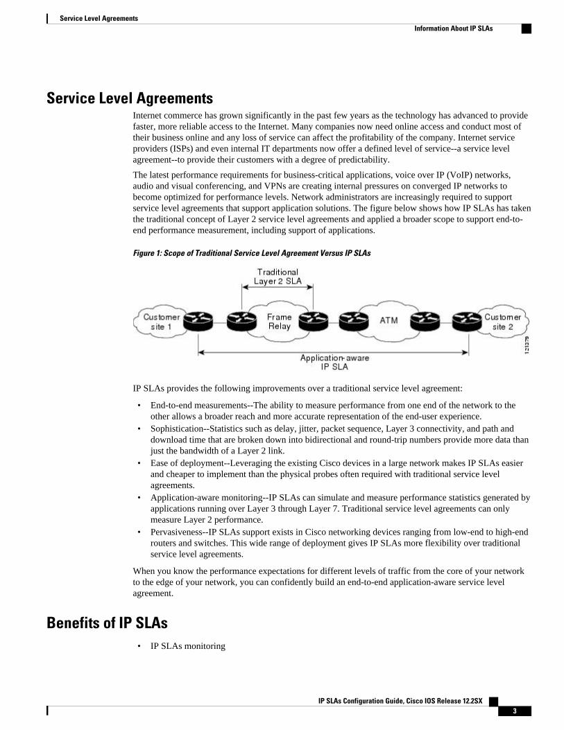
The latest performance requirements for business-critical applications, voice over IP (VoIP) networks,audio and visual conferencing, and VPNs are creating internal pressures on converged IP networks tobecome optimized for performance levels. Network administrators are increasingly required to supportservice level agreements that support application solutions. The figure below shows how IP SLAs has takenthe traditional concept of Layer 2 service level agreements and applied a broader scope to support end-to-end performance measurement, including support of applications.
Figure 1: Scope of Traditional Service Level Agreement Versus IP SLAs
IP SLAs provides the following improvements over a traditional service level agreement:
• End-to-end measurements--The ability to measure performance from one end of the network to theother allows a broader reach and more accurate representation of the end-user experience.
• Sophistication--Statistics such as delay, jitter, packet sequence, Layer 3 connectivity, and path anddownload time that are broken down into bidirectional and round-trip numbers provide more data thanjust the bandwidth of a Layer 2 link.
• Ease of deployment--Leveraging the existing Cisco devices in a large network makes IP SLAs easierand cheaper to implement than the physical probes often required with traditional service levelagreements.
• Application-aware monitoring--IP SLAs can simulate and measure performance statistics generated byapplications running over Layer 3 through Layer 7. Traditional service level agreements can onlymeasure Layer 2 performance.
• Pervasiveness--IP SLAs support exists in Cisco networking devices ranging from low-end to high-endrouters and switches. This wide range of deployment gives IP SLAs more flexibility over traditionalservice level agreements.
When you know the performance expectations for different levels of traffic from the core of your networkto the edge of your network, you can confidently build an end-to-end application-aware service levelagreement.
Benefits of IP SLAs• IP SLAs monitoring
Service Level AgreementsInformation About IP SLAs
IP SLAs Configuration Guide, Cisco IOS Release 12.2SX 3
◦ Provides service level agreement monitoring, measurement, and verification.• Network performance monitoring
◦ Measures the jitter, latency, or packet loss in the network.◦ Provides continuous, reliable, and predictable measurements.
• IP service network health assessment
◦ Verifies that the existing QoS is sufficient for new IP services.• Edge-to-edge network availability monitoring
◦ Provides proactive verification and connectivity testing of network resources (for example,indicates the network availability of a Network File System (NFS) server used to store businesscritical data from a remote site).
• Troubleshooting of network operation
◦ Provides consistent, reliable measurement that immediately identifies problems and savestroubleshooting time.
• Voice over IP (VoIP) performance monitoring• Multiprotocol Label Switching (MPLS) Virtual Private Network (VPN) performance monitoring and
network verification
Network Performance Measurement Using IP SLAsUsing IP SLAs, a network engineer can monitor the performance between any area in the network: core,distribution, and edge. Monitoring can be done anytime, anywhere, without deploying a physical probe.
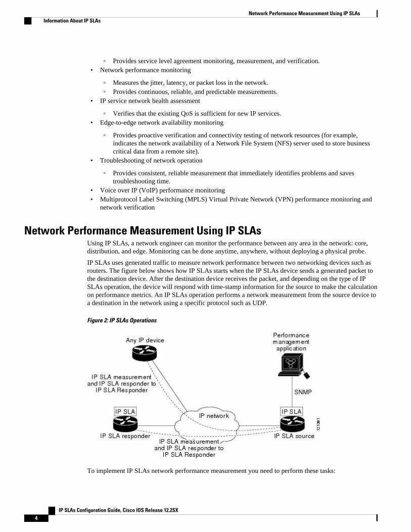
IP SLAs uses generated traffic to measure network performance between two networking devices such asrouters. The figure below shows how IP SLAs starts when the IP SLAs device sends a generated packet tothe destination device. After the destination device receives the packet, and depending on the type of IPSLAs operation, the device will respond with time-stamp information for the source to make the calculationon performance metrics. An IP SLAs operation performs a network measurement from the source device toa destination in the network using a specific protocol such as UDP.
Figure 2: IP SLAs Operations
To implement IP SLAs network performance measurement you need to perform these tasks:
Network Performance Measurement Using IP SLAs Information About IP SLAs
IP SLAs Configuration Guide, Cisco IOS Release 12.2SX4
1 Enable the IP SLAs Responder, if appropriate.2 Configure the required IP SLAs operation type.3 Configure any options available for the specified IP SLAs operation type.4 Configure threshold conditions, if required.5 Schedule the operation to run, then let the operation run for a period of time to gather statistics.6 Display and interpret the results of the operation using Cisco software commands or an NMS system
with SNMP.
Conceptual information about the IP SLAs Responder and IP SLAs control protocol, the various IP SLAsoperation types, thresholding options, and scheduling options are contained in this document.
IP SLAs Operation TypesThe various types of IP SLAs operations include the following:
• Data Link Switching Plus (DLSw+)• Domain Name System (DNS)• Dynamic Host Control Protocol (DHCP)• File Transfer Protocol (FTP)• Hypertext Transfer Protocol (HTTP)• ICMP echo• ICMP jitter• ICMP path echo• ICMP path jitter• Real-Time Transport Protocol (RTP)-based VoIP• Transmission Control Protocol (TCP) connect• UDP echo• UDP jitter• UDP jitter for VoIP• VoIP gatekeeper registration delay• VoIP post-dial delay
IP SLAs Responder and IP SLAs Control ProtocolThe IP SLAs Responder is a component embedded in the destination Cisco routing device that allows thesystem to anticipate and respond to IP SLAs request packets. The IP SLAs Responder provides anenormous advantage with accurate measurements without the need for dedicated probes and additionalstatistics not available via standard ICMP-based measurements. The patented IP SLAs Control Protocol isused by the IP SLAs Responder providing a mechanism through which the responder can be notified onwhich port it should listen and respond. Only a Cisco device can be a source for a destination IP SLAsResponder.
The figure "Cisco IOS XE IP SLAs Operations" in the "Network Performance Measurement Using CiscoIOS XE IP SLAs" section shows where the IP SLAs Responder fits in relation to the IP network. The IPSLAs Responder listens on a specific port for control protocol messages sent by an IP SLAs operation.Upon receipt of the control message, the responder will enable the specified UDP or TCP port for thespecified duration. During this time, the responder accepts the requests and responds to them. Theresponder disables the port after it responds to the IP SLAs packet, or when the specified time expires. Foradded security, MD5 authentication for control messages is available.
Enabling the IP SLAs Responder on the destination device is not required for all IP SLAs operations. Forexample, if services that are already provided by the destination router (such as Telnet or HTTP) are
IP SLAs Operation TypesInformation About IP SLAs
IP SLAs Configuration Guide, Cisco IOS Release 12.2SX 5
chosen, the IP SLAs Responder need not be enabled. For non-Cisco devices, the IP SLAs Respondercannot be configured and IP SLAs can send operational packets only to services native to those devices.
Response Time Computation for IP SLAsRouters may take tens of milliseconds to process incoming packets, due to other high-priority processes.This delay affects the response times because the reply to test packets might be sitting on queue whilewaiting to be processed. In this situation, the response times would not accurately represent true networkdelays. IP SLAs minimizes these processing delays on the source router as well as on the target router (if IPSLAs Responder is being used), in order to determine true round-trip times. IP SLAs test packets use timestamping to minimize the processing delays.
When enabled, the IP SLAs Responder allows the target device to take two time stamps both when thepacket arrives on the interface at interrupt level and again just as it is leaving, eliminating the processingtime. At times of high network activity, an ICMP ping test often shows a long and inaccurate responsetime, while an IP SLAs test shows an accurate response time due to the time stamping on the responder.
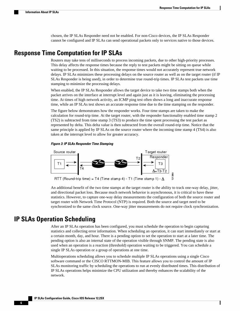
The figure below demonstrates how the responder works. Four time stamps are taken to make thecalculation for round-trip time. At the target router, with the responder functionality enabled time stamp 2(TS2) is subtracted from time stamp 3 (TS3) to produce the time spent processing the test packet asrepresented by delta. This delta value is then subtracted from the overall round-trip time. Notice that thesame principle is applied by IP SLAs on the source router where the incoming time stamp 4 (TS4) is alsotaken at the interrupt level to allow for greater accuracy.
Figure 3: IP SLAs Responder Time Stamping
An additional benefit of the two time stamps at the target router is the ability to track one-way delay, jitter,and directional packet loss. Because much network behavior is asynchronous, it is critical to have thesestatistics. However, to capture one-way delay measurements the configuration of both the source router andtarget router with Network Time Protocol (NTP) is required. Both the source and target need to besynchronized to the same clock source. One-way jitter measurements do not require clock synchronization.
IP SLAs Operation SchedulingAfter an IP SLAs operation has been configured, you must schedule the operation to begin capturingstatistics and collecting error information. When scheduling an operation, it can start immediately or start ata certain month, day, and hour. There is a pending option to set the operation to start at a later time. Thepending option is also an internal state of the operation visible through SNMP. The pending state is alsoused when an operation is a reaction (threshold) operation waiting to be triggered. You can schedule asingle IP SLAs operation or a group of operations at one time.
Multioperations scheduling allows you to schedule multiple IP SLAs operations using a single Ciscosoftware command or the CISCO RTTMON-MIB. This feature allows you to control the amount of IPSLAs monitoring traffic by scheduling the operations to run at evenly distributed times. This distribution ofIP SLAs operations helps minimize the CPU utilization and thereby enhances the scalability of thenetwork.
Response Time Computation for IP SLAs Information About IP SLAs
IP SLAs Configuration Guide, Cisco IOS Release 12.2SX6
For more details about the IP SLAs multioperations scheduling functionality, see the “IP SLAs-Multioperation Scheduling of IP SLAs Operations” module of the IP SLAs Configuration Guide .
IP SLAs Operation Threshold MonitoringTo support successful service level agreement monitoring or to proactively measure network performance,threshold functionality becomes essential. Consistent reliable measurements immediately identify issuesand can save troubleshooting time. To confidently roll out a service level agreement you need to havemechanisms that notify you immediately of any possible violation. IP SLAs can send SNMP traps that aretriggered by events such as the following:
• Connection loss• Timeout• Round-trip time threshold• Average jitter threshold• One-way packet loss• One-way jitter• One-way mean opinion score (MOS)• One-way latency
Alternately, an IP SLAs threshold violation can trigger another IP SLAs operation for further analysis. Forexample, the frequency could be increased or an ICMP path echo or ICMP path jitter operation could beinitiated for troubleshooting.
Determining the type of threshold and the level to set can be complex, and it depends on the type of IPservice being used in the network. For more details on using thresholds with IP SLAs operations, see the“IP SLAs-Proactive Threshold Monitoring of IP SLAs Operations” module of the IP SLAs ConfigurationGuide .
MPLS VPN AwarenessThe IP SLAs MPLS VPN Awareness feature provides the capability to monitor IP service levels withinMultiprotocol Label Switching (MPLS) Virtual Private Networks (VPNs). Using IP SLAs within MPLSVPNs allows service providers to plan, provision, and manage IP VPN services according to the servicelevel agreement for a customer. IP SLAs operations can be configured for a specific VPN by specifying aVPN routing and forwarding (VRF) name.
History StatisticsIP SLAs maintains the following three types of history statistics:
• Aggregated statistics--By default, IP SLAs maintains two hours of aggregated statistics for eachoperation. Value from each operation cycle is aggregated with the previously available data within agiven hour. The Enhanced History feature in IP SLAs allows for the aggregation interval to be shorterthan an hour.
• Operation snapshot history--IP SLAs maintains a snapshot of data for each operation instance thatmatches a configurable filter, such as all, over threshold, or failures. The entire set of data is availableand no aggregation takes place.
• Distribution statistics--IP SLAs maintains a frequency distribution over configurable intervals. Eachtime IP SLAs starts an operation, a new history bucket is created until the number of history bucketsmatches the specified size or the lifetime of the operation expires. By default, the history for an IP
IP SLAs Operation Threshold MonitoringInformation About IP SLAs
IP SLAs Configuration Guide, Cisco IOS Release 12.2SX 7
SLAs operation is not collected. If history is collected, each bucket contains one or more historyentries from the operation. History buckets do not wrap.
Additional ReferencesRelated Documents
Related Topic Document Title
Cisco IOS commands Cisco IOS Master Commands List, All Releases
Cisco IOS IP SLAs commands Cisco IOS IP SLAs Command Reference
Standards
Standards Title
ITU-T G.711 u-law and G.711 a-law Pulse code modulation (PCM) of voice frequencies
ITU-T G.729A Reduced complexity 8 kbit/s CS-ACELP speechcodec
MIBs
MIBs MIBs Link
CISCO-RTTMON-MIB To locate and download MIBs for selectedplatforms, Cisco IOS releases, and feature sets, useCisco MIB Locator found at the following URL:
http://www.cisco.com/go/mibs
RFCs
RFCs Title
No new or modified RFCs are supported by thisfeature, and support for existing RFCs has not beenmodified by this feature.
--
Technical Assistance
Description Link
The Cisco Support and Documentation websiteprovides online resources to downloaddocumentation, software, and tools. Use theseresources to install and configure the software andto troubleshoot and resolve technical issues withCisco products and technologies. Access to most
http://www.cisco.com/cisco/web/support/index.html
IP SLAs Overview Additional References
IP SLAs Configuration Guide, Cisco IOS Release 12.2SX8
Description Link
tools on the Cisco Support and Documentationwebsite requires a Cisco.com user ID andpassword.
Cisco and the Cisco Logo are trademarks of Cisco Systems, Inc. and/or its affiliates in the U.S. and othercountries. A listing of Cisco's trademarks can be found at www.cisco.com/go/trademarks. Third partytrademarks mentioned are the property of their respective owners. The use of the word partner does notimply a partnership relationship between Cisco and any other company. (1005R)
Any Internet Protocol (IP) addresses and phone numbers used in this document are not intended to beactual addresses and phone numbers. Any examples, command display output, network topology diagrams,and other figures included in the document are shown for illustrative purposes only. Any use of actual IPaddresses or phone numbers in illustrative content is unintentional and coincidental.
IP SLAs Overview
IP SLAs Configuration Guide, Cisco IOS Release 12.2SX 9

History Statistics
IP SLAs Configuration Guide, Cisco IOS Release 12.2SX10
Configuring IP SLAs UDP Jitter Operations
This document describes how to configure anIP Service Level Agreements (SLAs) UDP jitter operation toanalyze round-trip delay, one-way delay, one-way jitter, one-way packet loss, and connectivity innetworks that carry UDP traffic in IPv4 or IPv6 networks. This module also demonstrates how the datagathered using the UDP jitter operation can be displayed and analyzed using the Cisco softwarecommands.
• Finding Feature Information, page 11• Prerequisites, page 11• Information About IP SLAs UDP Jitter Operations, page 12• How to Configure IP SLAs UDP Jitter Operations, page 13• Configuration Examples for IP SLAs UDP Jitter Operations, page 21• Additional References, page 21• Feature Information for IP SLAs UDP Jitter Operations, page 22
Finding Feature InformationYour software release may not support all the features documented in this module. For the latest featureinformation and caveats, see the release notes for your platform and software release. To find informationabout the features documented in this module, and to see a list of the releases in which each feature issupported, see the Feature Information Table at the end of this document.
Use Cisco Feature Navigator to find information about platform support and Cisco software image support.To access Cisco Feature Navigator, go to www.cisco.com/go/cfn. An account on Cisco.com is not required.
Prerequisites• Time synchronization, such as that provided by NTP, is required between the source and the target
device in order to provide accurate one-way delay (latency) measurements. To configure NTP on thesource and target devices, perform the tasks in the “Performing Basic System Management” chapter ofthe Cisco IOS Network Management Configuration Guide. Time synchronization is not required forthe one-way jitter and packet loss measurements, however. If the time is not synchronized between thesource and target devices, one-way jitter and packet loss data will be returned, but values of “0” willbe returned for the one-way delay measurements provided by the UDP jitter operation.
• Before configuring any IP SLAs application, you can use the show ip sla application command toverify that the operation type is supported on your software image.
IP SLAs Configuration Guide, Cisco IOS Release 12.2SX 11
Information About IP SLAs UDP Jitter Operations• IP SLAs UDP Jitter Operation, page 12
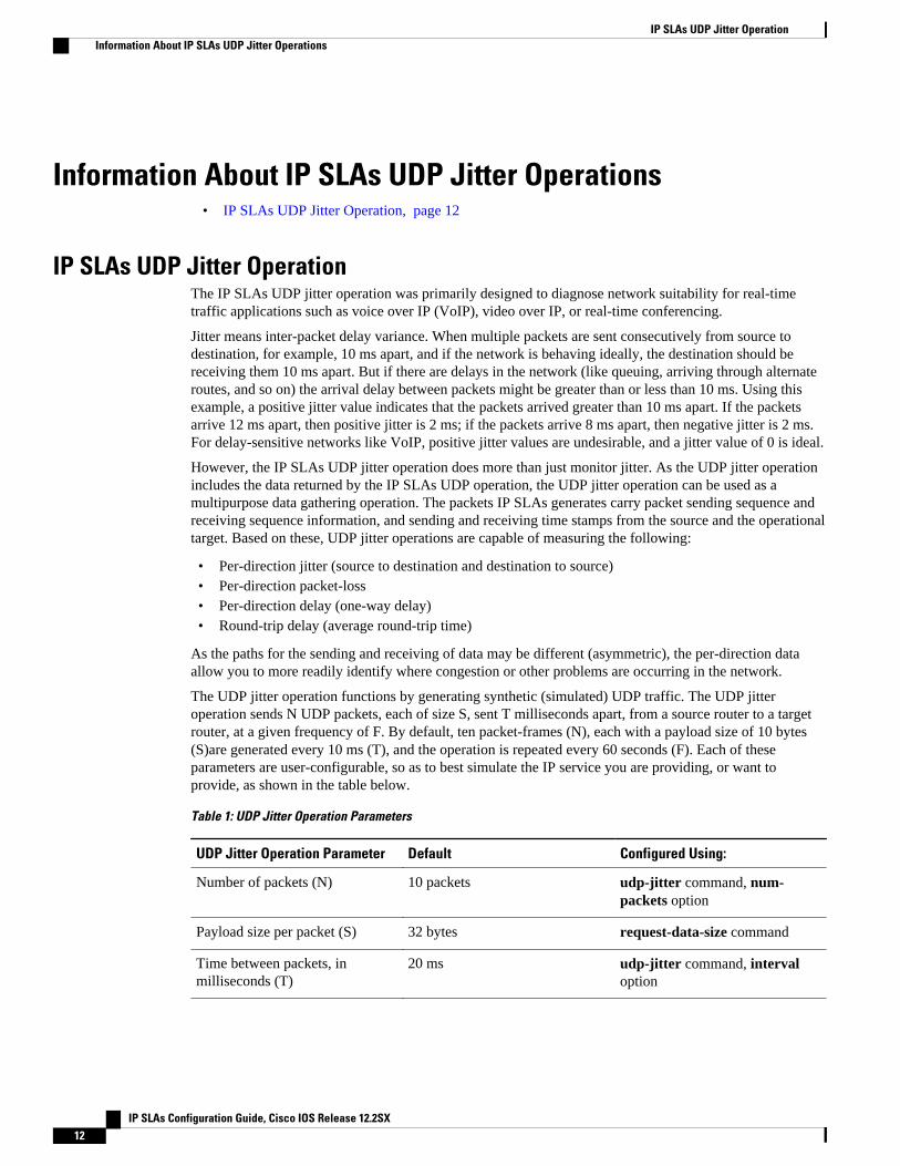
IP SLAs UDP Jitter OperationThe IP SLAs UDP jitter operation was primarily designed to diagnose network suitability for real-timetraffic applications such as voice over IP (VoIP), video over IP, or real-time conferencing.
Jitter means inter-packet delay variance. When multiple packets are sent consecutively from source todestination, for example, 10 ms apart, and if the network is behaving ideally, the destination should bereceiving them 10 ms apart. But if there are delays in the network (like queuing, arriving through alternateroutes, and so on) the arrival delay between packets might be greater than or less than 10 ms. Using thisexample, a positive jitter value indicates that the packets arrived greater than 10 ms apart. If the packetsarrive 12 ms apart, then positive jitter is 2 ms; if the packets arrive 8 ms apart, then negative jitter is 2 ms.For delay-sensitive networks like VoIP, positive jitter values are undesirable, and a jitter value of 0 is ideal.
However, the IP SLAs UDP jitter operation does more than just monitor jitter. As the UDP jitter operationincludes the data returned by the IP SLAs UDP operation, the UDP jitter operation can be used as amultipurpose data gathering operation. The packets IP SLAs generates carry packet sending sequence andreceiving sequence information, and sending and receiving time stamps from the source and the operationaltarget. Based on these, UDP jitter operations are capable of measuring the following:
• Per-direction jitter (source to destination and destination to source)• Per-direction packet-loss• Per-direction delay (one-way delay)• Round-trip delay (average round-trip time)
As the paths for the sending and receiving of data may be different (asymmetric), the per-direction dataallow you to more readily identify where congestion or other problems are occurring in the network.
The UDP jitter operation functions by generating synthetic (simulated) UDP traffic. The UDP jitteroperation sends N UDP packets, each of size S, sent T milliseconds apart, from a source router to a targetrouter, at a given frequency of F. By default, ten packet-frames (N), each with a payload size of 10 bytes(S)are generated every 10 ms (T), and the operation is repeated every 60 seconds (F). Each of theseparameters are user-configurable, so as to best simulate the IP service you are providing, or want toprovide, as shown in the table below.
Table 1: UDP Jitter Operation Parameters
UDP Jitter Operation Parameter Default Configured Using:
Number of packets (N) 10 packets udp-jitter command, num-packets option
Payload size per packet (S) 32 bytes request-data-size command
Time between packets, inmilliseconds (T)
20 ms udp-jitter command, intervaloption
IP SLAs UDP Jitter Operation Information About IP SLAs UDP Jitter Operations
IP SLAs Configuration Guide, Cisco IOS Release 12.2SX12
UDP Jitter Operation Parameter Default Configured Using:
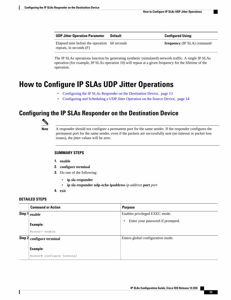
Elapsed time before the operationrepeats, in seconds (F)
60 seconds frequency (IP SLA) command
The IP SLAs operations function by generating synthetic (simulated) network traffic. A single IP SLAsoperation (for example, IP SLAs operation 10) will repeat at a given frequency for the lifetime of theoperation.
How to Configure IP SLAs UDP Jitter Operations• Configuring the IP SLAs Responder on the Destination Device, page 13
• Configuring and Scheduling a UDP Jitter Operation on the Source Device, page 14
Configuring the IP SLAs Responder on the Destination Device
Note A responder should not configure a permanent port for the same sender. If the responder configures thepermanent port for the same sender, even if the packets are successfully sent (no timeout or packet lossissues), the jitter values will be zero.
SUMMARY STEPS
1. enable
2. configure terminal
3. Do one of the following:
• ip sla responder• ip sla responder udp-echo ipaddress ip-address port port
4. exit
DETAILED STEPS
Command or Action Purpose
Step 1 enable
Example:
Router> enable
Enables privileged EXEC mode.
• Enter your password if prompted.
Step 2 configure terminal
Example:
Router# configure terminal
Enters global configuration mode.
Configuring the IP SLAs Responder on the Destination DeviceHow to Configure IP SLAs UDP Jitter Operations
IP SLAs Configuration Guide, Cisco IOS Release 12.2SX 13
Command or Action Purpose
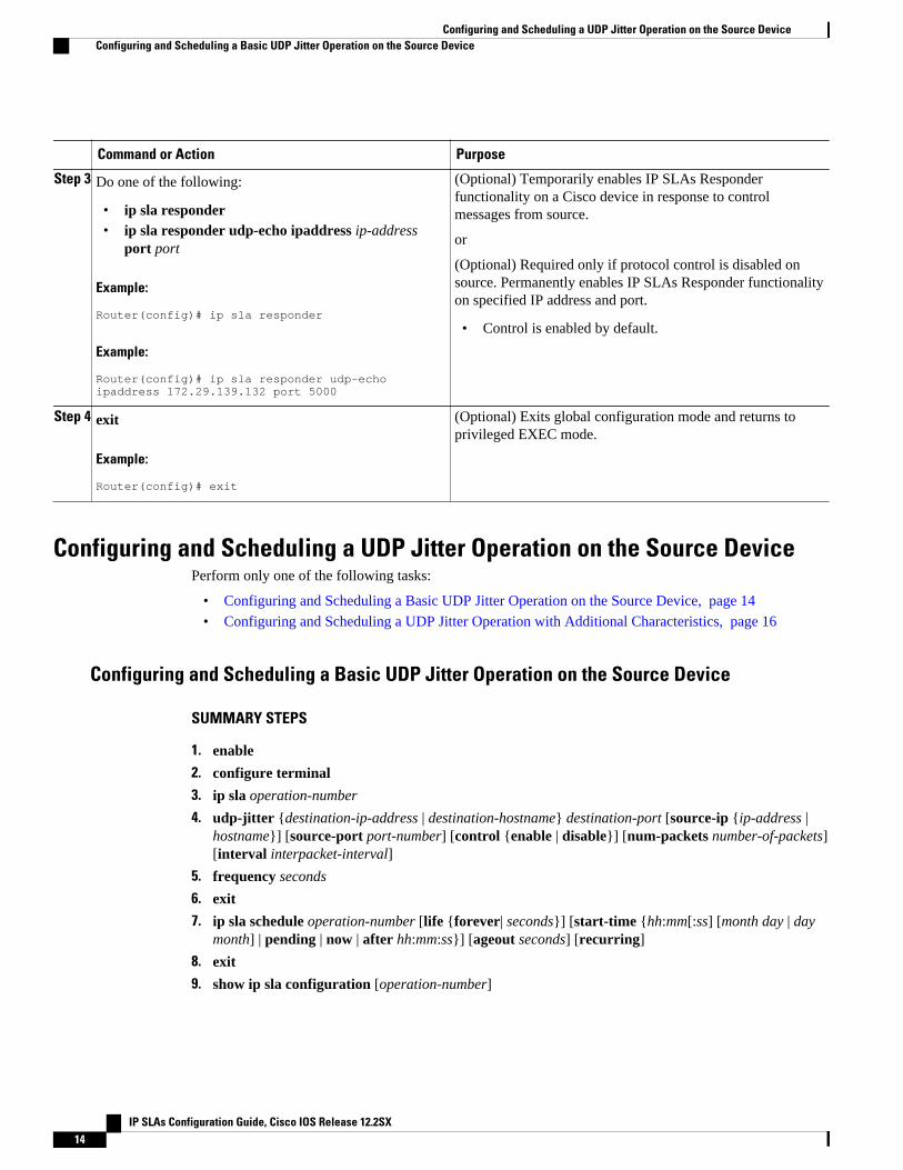
Step 3 Do one of the following:
• ip sla responder• ip sla responder udp-echo ipaddress ip-address
port port
Example:
Router(config)# ip sla responder
Example:
Router(config)# ip sla responder udp-echo ipaddress 172.29.139.132 port 5000
(Optional) Temporarily enables IP SLAs Responderfunctionality on a Cisco device in response to controlmessages from source.
or
(Optional) Required only if protocol control is disabled onsource. Permanently enables IP SLAs Responder functionalityon specified IP address and port.
• Control is enabled by default.
Step 4 exit
Example:
Router(config)# exit
(Optional) Exits global configuration mode and returns toprivileged EXEC mode.
Configuring and Scheduling a UDP Jitter Operation on the Source DevicePerform only one of the following tasks:
• Configuring and Scheduling a Basic UDP Jitter Operation on the Source Device, page 14
• Configuring and Scheduling a UDP Jitter Operation with Additional Characteristics, page 16
Configuring and Scheduling a Basic UDP Jitter Operation on the Source Device
SUMMARY STEPS
1. enable
2. configure terminal
3. ip sla operation-number
4. udp-jitter {destination-ip-address | destination-hostname} destination-port [source-ip {ip-address |hostname}] [source-port port-number] [control {enable | disable}] [num-packets number-of-packets][interval interpacket-interval]
5. frequency seconds
6. exit
7. ip sla schedule operation-number [life {forever| seconds}] [start-time {hh:mm[:ss] [month day | daymonth] | pending | now | after hh:mm:ss}] [ageout seconds] [recurring]
8. exit
9. show ip sla configuration [operation-number]
Configuring and Scheduling a UDP Jitter Operation on the Source Device Configuring and Scheduling a Basic UDP Jitter Operation on the Source Device
IP SLAs Configuration Guide, Cisco IOS Release 12.2SX14
DETAILED STEPS
Command or Action Purpose
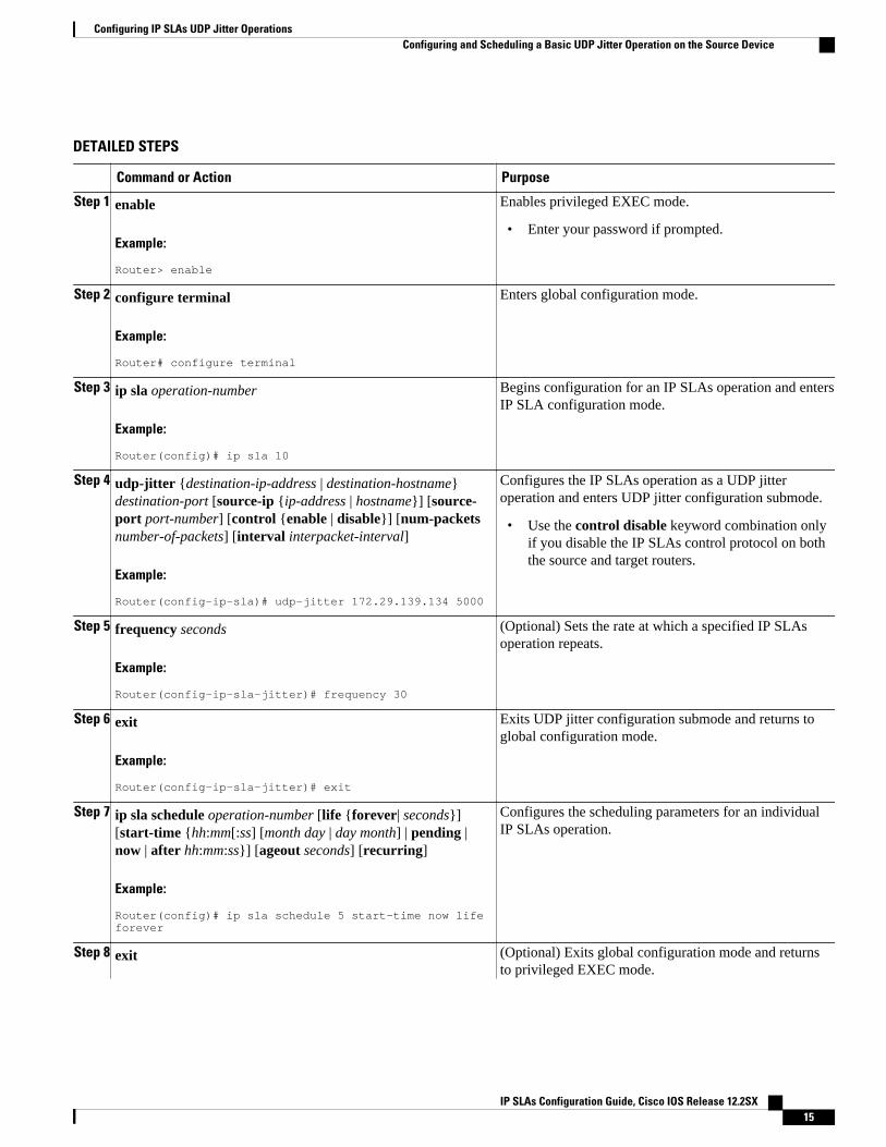
Step 1 enable
Example:
Router> enable
Enables privileged EXEC mode.
• Enter your password if prompted.
Step 2 configure terminal
Example:
Router# configure terminal
Enters global configuration mode.
Step 3 ip sla operation-number
Example:
Router(config)# ip sla 10
Begins configuration for an IP SLAs operation and entersIP SLA configuration mode.
Step 4 udp-jitter {destination-ip-address | destination-hostname}destination-port [source-ip {ip-address | hostname}] [source-port port-number] [control {enable | disable}] [num-packetsnumber-of-packets] [interval interpacket-interval]
Example:
Router(config-ip-sla)# udp-jitter 172.29.139.134 5000
Configures the IP SLAs operation as a UDP jitteroperation and enters UDP jitter configuration submode.
• Use the control disable keyword combination onlyif you disable the IP SLAs control protocol on boththe source and target routers.
Step 5 frequency seconds
Example:
Router(config-ip-sla-jitter)# frequency 30
(Optional) Sets the rate at which a specified IP SLAsoperation repeats.
Step 6 exit
Example:
Router(config-ip-sla-jitter)# exit
Exits UDP jitter configuration submode and returns toglobal configuration mode.
Step 7 ip sla schedule operation-number [life {forever| seconds}][start-time {hh:mm[:ss] [month day | day month] | pending |now | after hh:mm:ss}] [ageout seconds] [recurring]
Example:
Router(config)# ip sla schedule 5 start-time now life forever
Configures the scheduling parameters for an individualIP SLAs operation.
Step 8 exit (Optional) Exits global configuration mode and returnsto privileged EXEC mode.
Configuring IP SLAs UDP Jitter OperationsConfiguring and Scheduling a Basic UDP Jitter Operation on the Source Device
IP SLAs Configuration Guide, Cisco IOS Release 12.2SX 15
Command or Action Purpose
Example:
Router(config)# exit
Step 9 show ip sla configuration [operation-number]
Example:
Router# show ip sla configuration 10
(Optional) Displays configuration values including alldefaults for all IP SLAs operations or a specifiedoperation.
• Troubleshooting Tips, page 16
• What to Do Next, page 16
Troubleshooting Tips
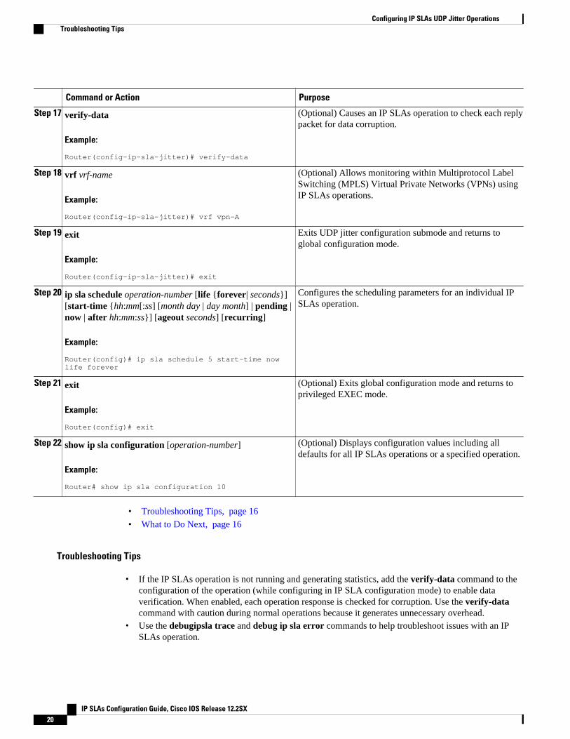
• If the IP SLAs operation is not running and generating statistics, add the verify-data command to theconfiguration of the operation (while configuring in IP SLA configuration mode) to enable dataverification. When enabled, each operation response is checked for corruption. Use the verify-datacommand with caution during normal operations because it generates unnecessary overhead.
• Use the debugipsla trace and debug ip sla error commands to help troubleshoot issues with an IPSLAs operation.
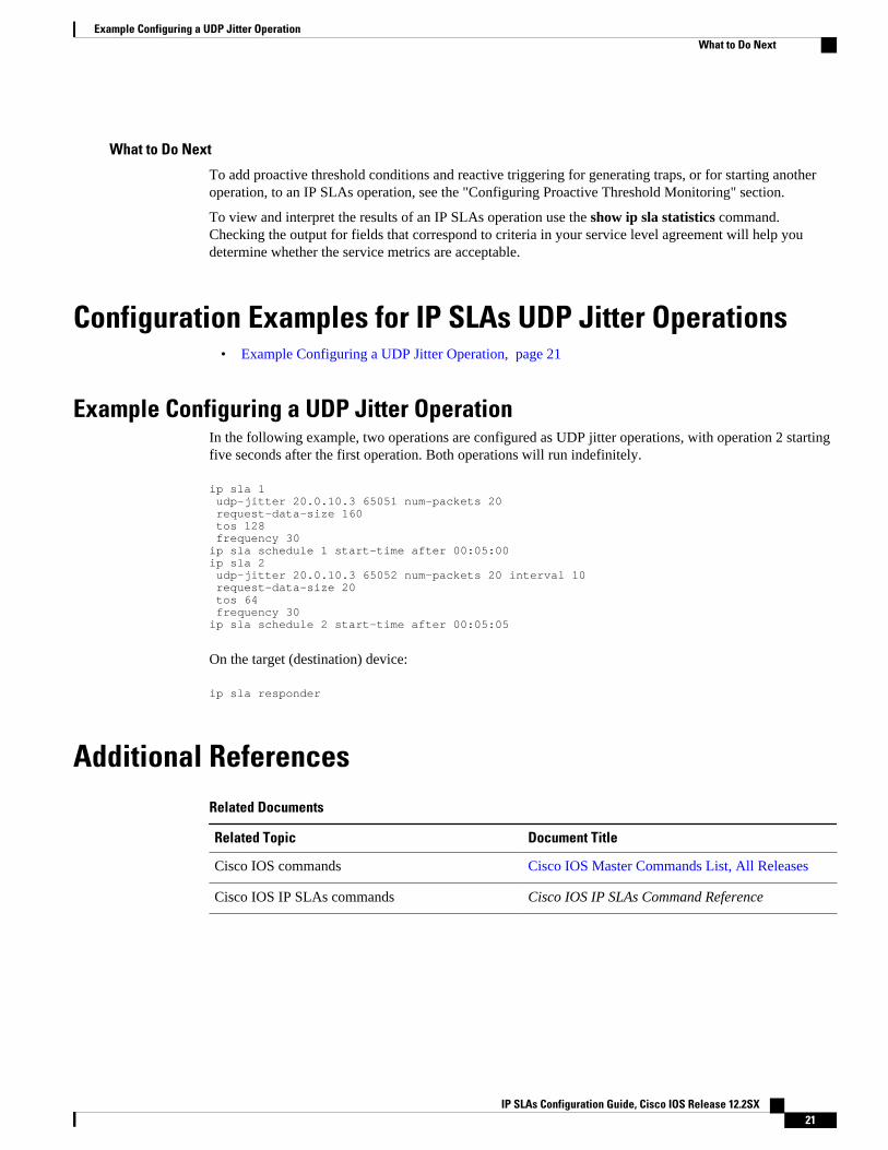
What to Do Next
To add proactive threshold conditions and reactive triggering for generating traps, or for starting anotheroperation, to an IP SLAs operation, see the "Configuring Proactive Threshold Monitoring" section.
To view and interpret the results of an IP SLAs operation use the show ip sla statistics command.Checking the output for fields that correspond to criteria in your service level agreement will help youdetermine whether the service metrics are acceptable.
Configuring and Scheduling a UDP Jitter Operation with Additional Characteristics
Note• The IP SLAs UDP jitter operation does not support the IP SLAs History feature (statistics history
buckets) because of the large data volume involved with UDP jitter operations. This means that thefollowing commands are not supported for UDP jitter operations: history buckets-kept, history filter,history lives-kept, samples-of-history-kept, and show ip sla history.
• The MIB used by IP SLAs (CISCO-RTTMON-MIB) limits the hours-of-statistics kept for the UDPjitter operation to two hours. Configuring a larger value using the history hours-of-statisticshoursglobal configuration change will not increase the value beyond two hours. However, the DataCollection MIB can be used to collect historical data for the operation. For information, see theCISCO-DATA-COLLECTION-MIB at http://www.cisco.com/go/mibs ).
Before configuring a UDP jitter operation on the source device, the IP SLAs Responder must be enabled onthe target device (the operational target). The IP SLAs Responder is available only on Cisco IOS software-
Configuring IP SLAs UDP Jitter Operations Troubleshooting Tips
IP SLAs Configuration Guide, Cisco IOS Release 12.2SX16
based devices. To enable the Responder, perform the task in the “Configuring the IP SLAs Responder onthe Destination Device” section.
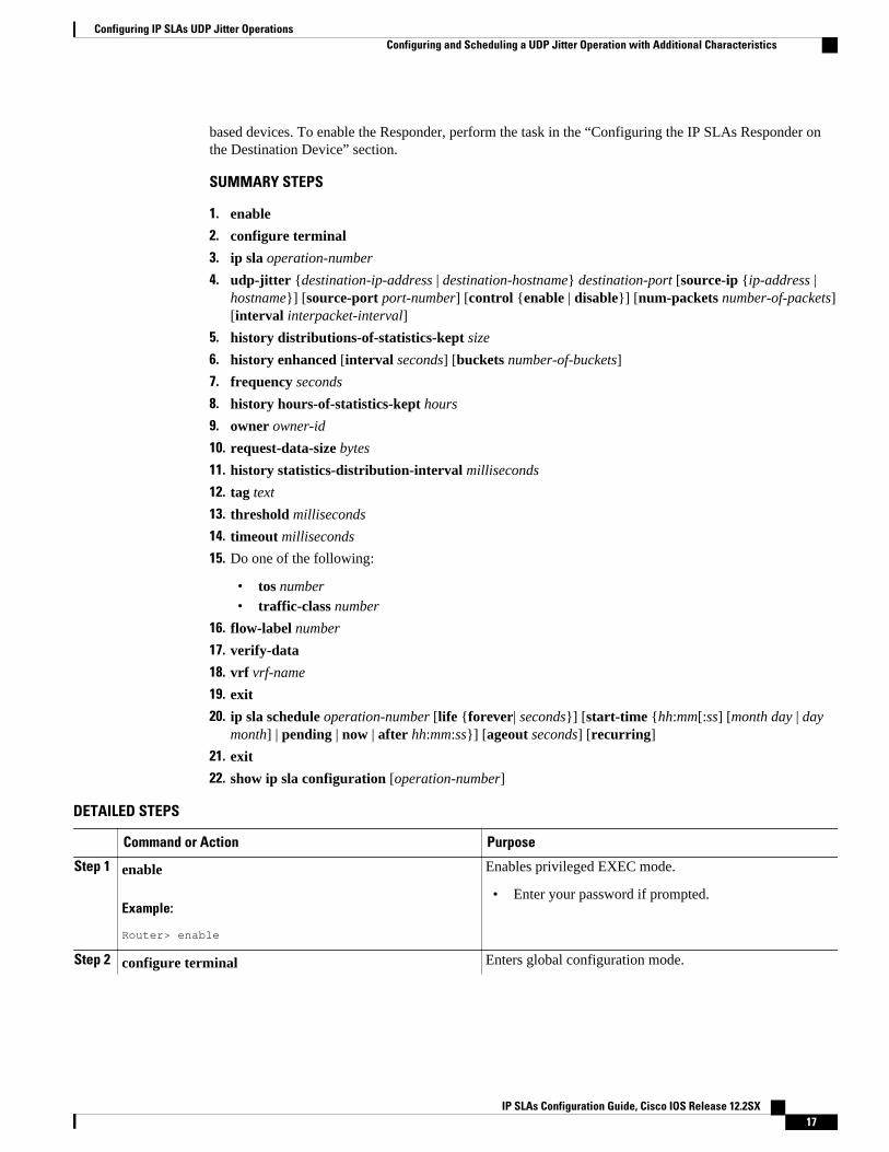
SUMMARY STEPS
1. enable
2. configure terminal
3. ip sla operation-number
4. udp-jitter {destination-ip-address | destination-hostname} destination-port [source-ip {ip-address |hostname}] [source-port port-number] [control {enable | disable}] [num-packets number-of-packets][interval interpacket-interval]
5. history distributions-of-statistics-kept size
6. history enhanced [interval seconds] [buckets number-of-buckets]
7. frequency seconds
8. history hours-of-statistics-kept hours
9. owner owner-id
10. request-data-size bytes
11. history statistics-distribution-interval milliseconds
12. tag text
13. threshold milliseconds
14. timeout milliseconds
15. Do one of the following:
• tos number• traffic-class number
16. flow-label number
17. verify-data
18. vrf vrf-name
19. exit
20. ip sla schedule operation-number [life {forever| seconds}] [start-time {hh:mm[:ss] [month day | daymonth] | pending | now | after hh:mm:ss}] [ageout seconds] [recurring]
21. exit
22. show ip sla configuration [operation-number]
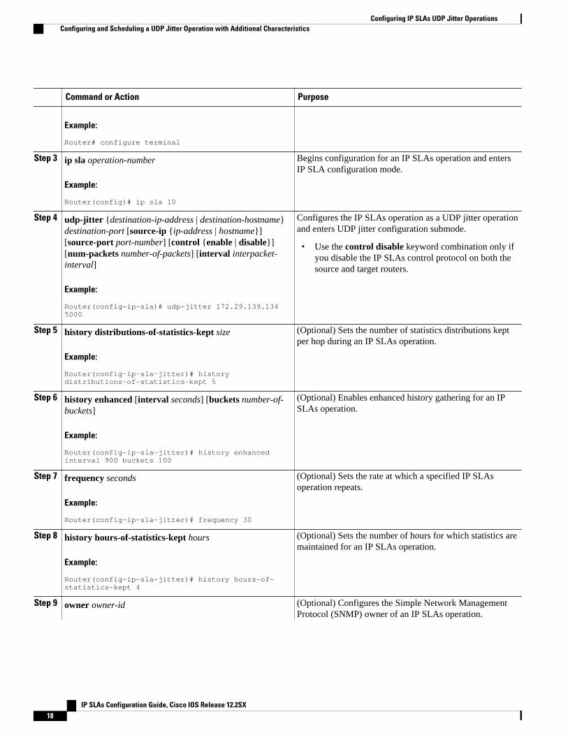
DETAILED STEPS
Command or Action Purpose
Step 1 enable
Example:
Router> enable
Enables privileged EXEC mode.
• Enter your password if prompted.
Step 2 configure terminal Enters global configuration mode.
Configuring IP SLAs UDP Jitter OperationsConfiguring and Scheduling a UDP Jitter Operation with Additional Characteristics
IP SLAs Configuration Guide, Cisco IOS Release 12.2SX 17
Command or Action Purpose
Example:
Router# configure terminal
Step 3 ip sla operation-number
Example:
Router(config)# ip sla 10
Begins configuration for an IP SLAs operation and entersIP SLA configuration mode.
Step 4 udp-jitter {destination-ip-address | destination-hostname}destination-port [source-ip {ip-address | hostname}][source-port port-number] [control {enable | disable}][num-packets number-of-packets] [interval interpacket-interval]
Example:
Router(config-ip-sla)# udp-jitter 172.29.139.134 5000
Configures the IP SLAs operation as a UDP jitter operationand enters UDP jitter configuration submode.
• Use the control disable keyword combination only ifyou disable the IP SLAs control protocol on both thesource and target routers.
Step 5 history distributions-of-statistics-kept size
Example:
Router(config-ip-sla-jitter)# history distributions-of-statistics-kept 5
(Optional) Sets the number of statistics distributions keptper hop during an IP SLAs operation.
Step 6 history enhanced [interval seconds] [buckets number-of-buckets]
Example:
Router(config-ip-sla-jitter)# history enhanced interval 900 buckets 100
(Optional) Enables enhanced history gathering for an IPSLAs operation.
Step 7 frequency seconds
Example:
Router(config-ip-sla-jitter)# frequency 30
(Optional) Sets the rate at which a specified IP SLAsoperation repeats.
Step 8 history hours-of-statistics-kept hours
Example:
Router(config-ip-sla-jitter)# history hours-of-statistics-kept 4
(Optional) Sets the number of hours for which statistics aremaintained for an IP SLAs operation.
Step 9 owner owner-id (Optional) Configures the Simple Network ManagementProtocol (SNMP) owner of an IP SLAs operation.
Configuring IP SLAs UDP Jitter Operations Configuring and Scheduling a UDP Jitter Operation with Additional Characteristics
IP SLAs Configuration Guide, Cisco IOS Release 12.2SX18
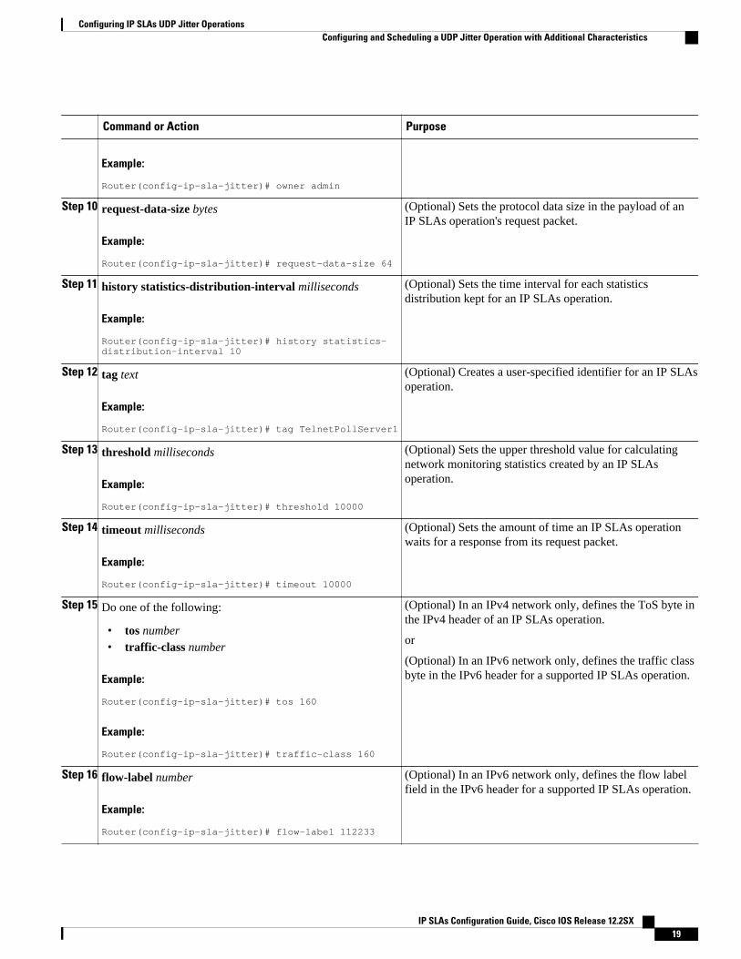
Command or Action Purpose
Example:
Router(config-ip-sla-jitter)# owner admin
Step 10 request-data-size bytes
Example:
Router(config-ip-sla-jitter)# request-data-size 64
(Optional) Sets the protocol data size in the payload of anIP SLAs operation's request packet.
Step 11 history statistics-distribution-interval milliseconds
Example:
Router(config-ip-sla-jitter)# history statistics-distribution-interval 10
(Optional) Sets the time interval for each statisticsdistribution kept for an IP SLAs operation.
Step 12 tag text
Example:
Router(config-ip-sla-jitter)# tag TelnetPollServer1
(Optional) Creates a user-specified identifier for an IP SLAsoperation.
Step 13 threshold milliseconds
Example:
Router(config-ip-sla-jitter)# threshold 10000
(Optional) Sets the upper threshold value for calculatingnetwork monitoring statistics created by an IP SLAsoperation.
Step 14 timeout milliseconds
Example:
Router(config-ip-sla-jitter)# timeout 10000
(Optional) Sets the amount of time an IP SLAs operationwaits for a response from its request packet.
Step 15 Do one of the following:
• tos number• traffic-class number
Example:
Router(config-ip-sla-jitter)# tos 160
Example:
Router(config-ip-sla-jitter)# traffic-class 160
(Optional) In an IPv4 network only, defines the ToS byte inthe IPv4 header of an IP SLAs operation.
or
(Optional) In an IPv6 network only, defines the traffic classbyte in the IPv6 header for a supported IP SLAs operation.
Step 16 flow-label number
Example:
Router(config-ip-sla-jitter)# flow-label 112233
(Optional) In an IPv6 network only, defines the flow labelfield in the IPv6 header for a supported IP SLAs operation.
Configuring IP SLAs UDP Jitter OperationsConfiguring and Scheduling a UDP Jitter Operation with Additional Characteristics
IP SLAs Configuration Guide, Cisco IOS Release 12.2SX 19
Command or Action Purpose
Step 17 verify-data
Example:
Router(config-ip-sla-jitter)# verify-data
(Optional) Causes an IP SLAs operation to check each replypacket for data corruption.
Step 18 vrf vrf-name
Example:
Router(config-ip-sla-jitter)# vrf vpn-A
(Optional) Allows monitoring within Multiprotocol LabelSwitching (MPLS) Virtual Private Networks (VPNs) usingIP SLAs operations.
Step 19 exit
Example:
Router(config-ip-sla-jitter)# exit
Exits UDP jitter configuration submode and returns toglobal configuration mode.
Step 20 ip sla schedule operation-number [life {forever| seconds}][start-time {hh:mm[:ss] [month day | day month] | pending |now | after hh:mm:ss}] [ageout seconds] [recurring]
Example:
Router(config)# ip sla schedule 5 start-time now life forever
Configures the scheduling parameters for an individual IPSLAs operation.
Step 21 exit
Example:
Router(config)# exit
(Optional) Exits global configuration mode and returns toprivileged EXEC mode.
Step 22 show ip sla configuration [operation-number]
Example:
Router# show ip sla configuration 10
(Optional) Displays configuration values including alldefaults for all IP SLAs operations or a specified operation.
• Troubleshooting Tips, page 16
• What to Do Next, page 16
Troubleshooting Tips
• If the IP SLAs operation is not running and generating statistics, add the verify-data command to theconfiguration of the operation (while configuring in IP SLA configuration mode) to enable dataverification. When enabled, each operation response is checked for corruption. Use the verify-datacommand with caution during normal operations because it generates unnecessary overhead.
• Use the debugipsla trace and debug ip sla error commands to help troubleshoot issues with an IPSLAs operation.
Configuring IP SLAs UDP Jitter Operations Troubleshooting Tips
IP SLAs Configuration Guide, Cisco IOS Release 12.2SX20
What to Do Next
To add proactive threshold conditions and reactive triggering for generating traps, or for starting anotheroperation, to an IP SLAs operation, see the "Configuring Proactive Threshold Monitoring" section.
To view and interpret the results of an IP SLAs operation use the show ip sla statistics command.Checking the output for fields that correspond to criteria in your service level agreement will help youdetermine whether the service metrics are acceptable.
Configuration Examples for IP SLAs UDP Jitter Operations• Example Configuring a UDP Jitter Operation, page 21
Example Configuring a UDP Jitter OperationIn the following example, two operations are configured as UDP jitter operations, with operation 2 startingfive seconds after the first operation. Both operations will run indefinitely.
ip sla 1 udp-jitter 20.0.10.3 65051 num-packets 20 request-data-size 160 tos 128 frequency 30ip sla schedule 1 start-time after 00:05:00ip sla 2 udp-jitter 20.0.10.3 65052 num-packets 20 interval 10 request-data-size 20 tos 64 frequency 30ip sla schedule 2 start-time after 00:05:05
On the target (destination) device:
ip sla responder
Additional ReferencesRelated Documents
Related Topic Document Title
Cisco IOS commands Cisco IOS Master Commands List, All Releases
Cisco IOS IP SLAs commands Cisco IOS IP SLAs Command Reference
Example Configuring a UDP Jitter OperationWhat to Do Next
IP SLAs Configuration Guide, Cisco IOS Release 12.2SX 21
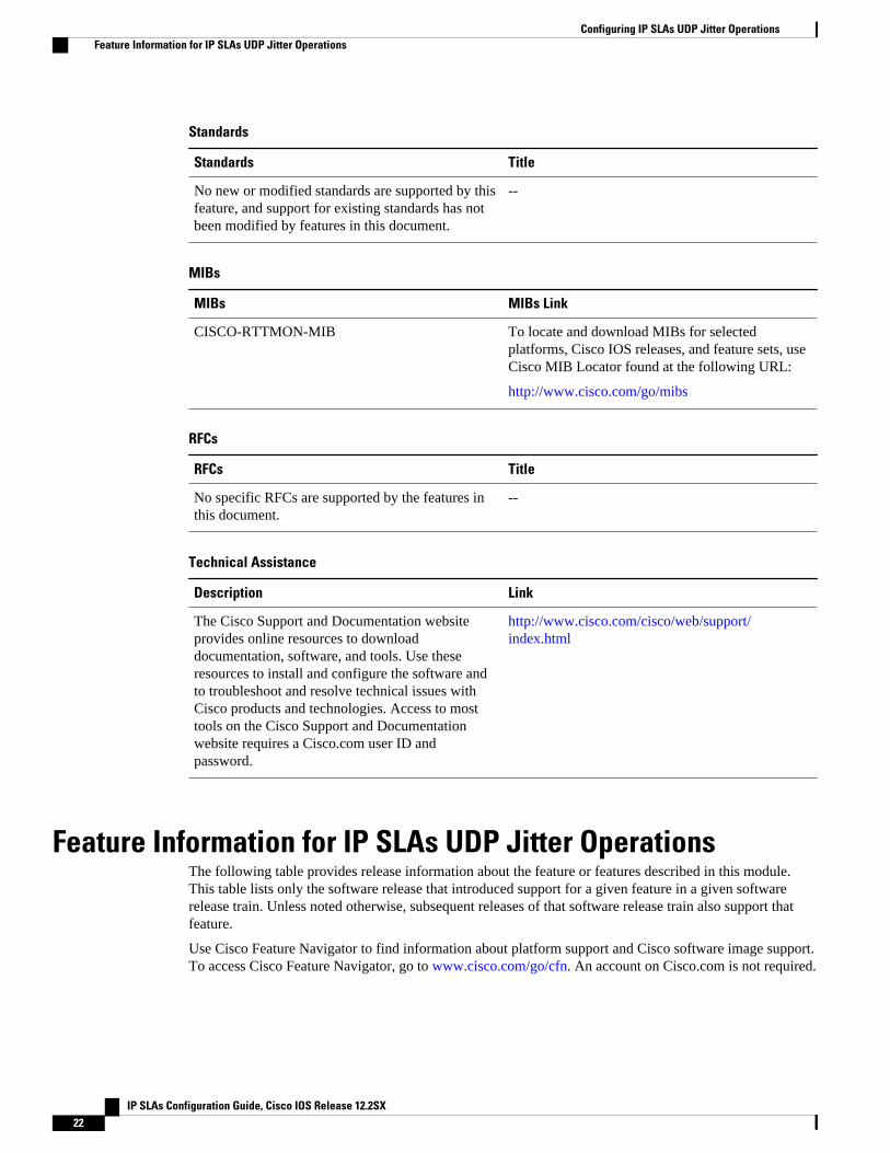
Standards
Standards Title
No new or modified standards are supported by thisfeature, and support for existing standards has notbeen modified by features in this document.
--
MIBs
MIBs MIBs Link
CISCO-RTTMON-MIB To locate and download MIBs for selectedplatforms, Cisco IOS releases, and feature sets, useCisco MIB Locator found at the following URL:
http://www.cisco.com/go/mibs
RFCs
RFCs Title
No specific RFCs are supported by the features inthis document.
--
Technical Assistance
Description Link
The Cisco Support and Documentation websiteprovides online resources to downloaddocumentation, software, and tools. Use theseresources to install and configure the software andto troubleshoot and resolve technical issues withCisco products and technologies. Access to mosttools on the Cisco Support and Documentationwebsite requires a Cisco.com user ID andpassword.
http://www.cisco.com/cisco/web/support/index.html
Feature Information for IP SLAs UDP Jitter OperationsThe following table provides release information about the feature or features described in this module.This table lists only the software release that introduced support for a given feature in a given softwarerelease train. Unless noted otherwise, subsequent releases of that software release train also support thatfeature.
Use Cisco Feature Navigator to find information about platform support and Cisco software image support.To access Cisco Feature Navigator, go to www.cisco.com/go/cfn. An account on Cisco.com is not required.
Configuring IP SLAs UDP Jitter Operations Feature Information for IP SLAs UDP Jitter Operations
IP SLAs Configuration Guide, Cisco IOS Release 12.2SX22
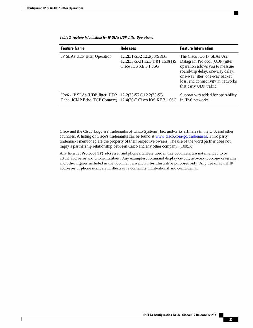
Table 2: Feature Information for IP SLAs UDP Jitter Operations
Feature Name Releases Feature Information
IP SLAs UDP Jitter Operation 12.2(31)SB2 12.2(33)SRB112.2(33)SXH 12.3(14)T 15.0(1)SCisco IOS XE 3.1.0SG
The Cisco IOS IP SLAs UserDatagram Protocol (UDP) jitteroperation allows you to measureround-trip delay, one-way delay,one-way jitter, one-way packetloss, and connectivity in networksthat carry UDP traffic.
IPv6 - IP SLAs (UDP Jitter, UDPEcho, ICMP Echo, TCP Connect)
12.2(33)SRC 12.2(33)SB12.4(20)T Cisco IOS XE 3.1.0SG
Support was added for operabilityin IPv6 networks.
Cisco and the Cisco Logo are trademarks of Cisco Systems, Inc. and/or its affiliates in the U.S. and othercountries. A listing of Cisco's trademarks can be found at www.cisco.com/go/trademarks. Third partytrademarks mentioned are the property of their respective owners. The use of the word partner does notimply a partnership relationship between Cisco and any other company. (1005R)
Any Internet Protocol (IP) addresses and phone numbers used in this document are not intended to beactual addresses and phone numbers. Any examples, command display output, network topology diagrams,and other figures included in the document are shown for illustrative purposes only. Any use of actual IPaddresses or phone numbers in illustrative content is unintentional and coincidental.
Configuring IP SLAs UDP Jitter Operations
IP SLAs Configuration Guide, Cisco IOS Release 12.2SX 23

Example Configuring a UDP Jitter Operation
IP SLAs Configuration Guide, Cisco IOS Release 12.2SX24
Configuring IP SLAs UDP Jitter Operations forVoIP
This document describes how to configure an IP Service Level Agreements (SLAs) User DatagramProtocol (UDP jitter operation to proactively monitor Voice over IP (VoIP) quality levels in your network,allowing you to guarantee VoIP quality levels to your users in IPv4 or IPv6 networks. The IP SLAs VoIPUDP jitter operation accurately simulates VoIP traffic using common codecs, and calculates consistentvoice quality scores (MOS and ICPIF) between Cisco devices in the network.
Note The term “Voice” in this document should be taken to mean any Internet telephony applications. The term“Voice over IP” can include the transmission of multimedia (both voice and video) over IP networks.
• Finding Feature Information, page 25• Restrictions for IP SLAs UDP Jitter Operations for VoIP, page 25• Information About IP SLAs UDP Jitter Operations for VoIP, page 26• How to Configure IP SLAs UDP Jitter Operations for VoIP, page 31• Configuration Examples for IP SLAs UDP Jitter Operations for VoIP, page 36• Additional References, page 38• Feature Information for IP SLAs UDP Jitter Operations for VoIP, page 40• Glossary, page 41
Finding Feature InformationYour software release may not support all the features documented in this module. For the latest featureinformation and caveats, see the release notes for your platform and software release. To find informationabout the features documented in this module, and to see a list of the releases in which each feature issupported, see the Feature Information Table at the end of this document.
Use Cisco Feature Navigator to find information about platform support and Cisco software image support.To access Cisco Feature Navigator, go to www.cisco.com/go/cfn. An account on Cisco.com is not required.
Restrictions for IP SLAs UDP Jitter Operations for VoIP
IP SLAs Configuration Guide, Cisco IOS Release 12.2SX 25
• This feature uses UDP traffic to generate approximate Voice over IP scores. It does not providesupport for the Real-Time Transport Protocol (RTP).
• ICPIF and MOS values provided by this feature, while consistent within IP SLAs, are estimates onlyand are intended only for relative comparisons. The values may not match values determined usingother methods.
• Predictions of customer opinion (such as those listed for the E-Model transmission rating factor R andderived Mean Opinion Scores) determined by any method are intended only for transmission planningand analysis purposes and should not be interpreted as reflecting actual customer opinions.
Information About IP SLAs UDP Jitter Operations for VoIP• The Calculated Planning Impairment Factor (ICPIF), page 26
• Mean Opinion Scores (MOS), page 27
• Voice Performance Monitoring Using IP SLAs, page 28
• Codec Simulation Within IP SLAs, page 28
• The IP SLAs ICPIF Value, page 29
• The IP SLAs MOS Value, page 31
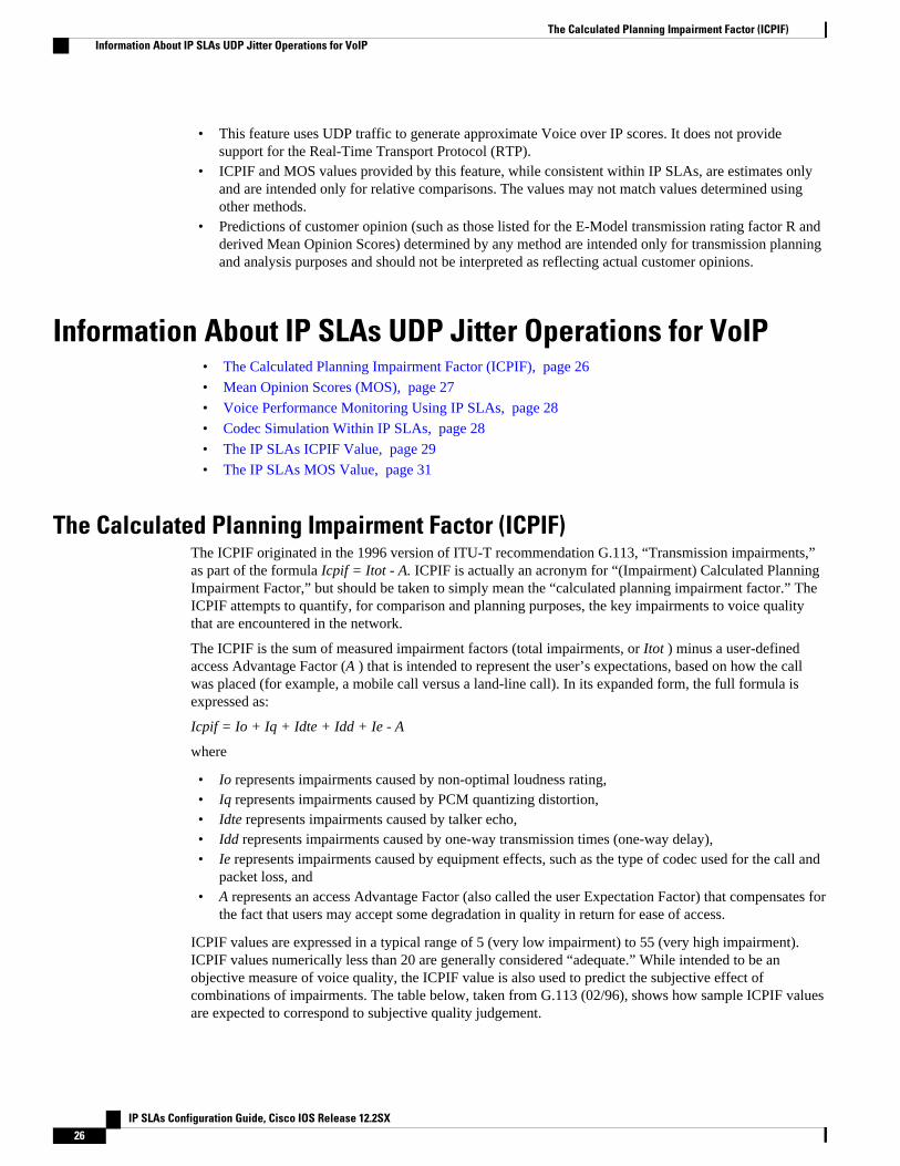
The Calculated Planning Impairment Factor (ICPIF)The ICPIF originated in the 1996 version of ITU-T recommendation G.113, “Transmission impairments,”as part of the formula Icpif = Itot - A. ICPIF is actually an acronym for “(Impairment) Calculated PlanningImpairment Factor,” but should be taken to simply mean the “calculated planning impairment factor.” TheICPIF attempts to quantify, for comparison and planning purposes, the key impairments to voice qualitythat are encountered in the network.
The ICPIF is the sum of measured impairment factors (total impairments, or Itot ) minus a user-definedaccess Advantage Factor (A ) that is intended to represent the user’s expectations, based on how the callwas placed (for example, a mobile call versus a land-line call). In its expanded form, the full formula isexpressed as:
Icpif = Io + Iq + Idte + Idd + Ie - A
where
• Io represents impairments caused by non-optimal loudness rating,• Iq represents impairments caused by PCM quantizing distortion,• Idte represents impairments caused by talker echo,• Idd represents impairments caused by one-way transmission times (one-way delay),• Ie represents impairments caused by equipment effects, such as the type of codec used for the call and
packet loss, and• A represents an access Advantage Factor (also called the user Expectation Factor) that compensates for
the fact that users may accept some degradation in quality in return for ease of access.
ICPIF values are expressed in a typical range of 5 (very low impairment) to 55 (very high impairment).ICPIF values numerically less than 20 are generally considered “adequate.” While intended to be anobjective measure of voice quality, the ICPIF value is also used to predict the subjective effect ofcombinations of impairments. The table below, taken from G.113 (02/96), shows how sample ICPIF valuesare expected to correspond to subjective quality judgement.
The Calculated Planning Impairment Factor (ICPIF) Information About IP SLAs UDP Jitter Operations for VoIP
IP SLAs Configuration Guide, Cisco IOS Release 12.2SX26
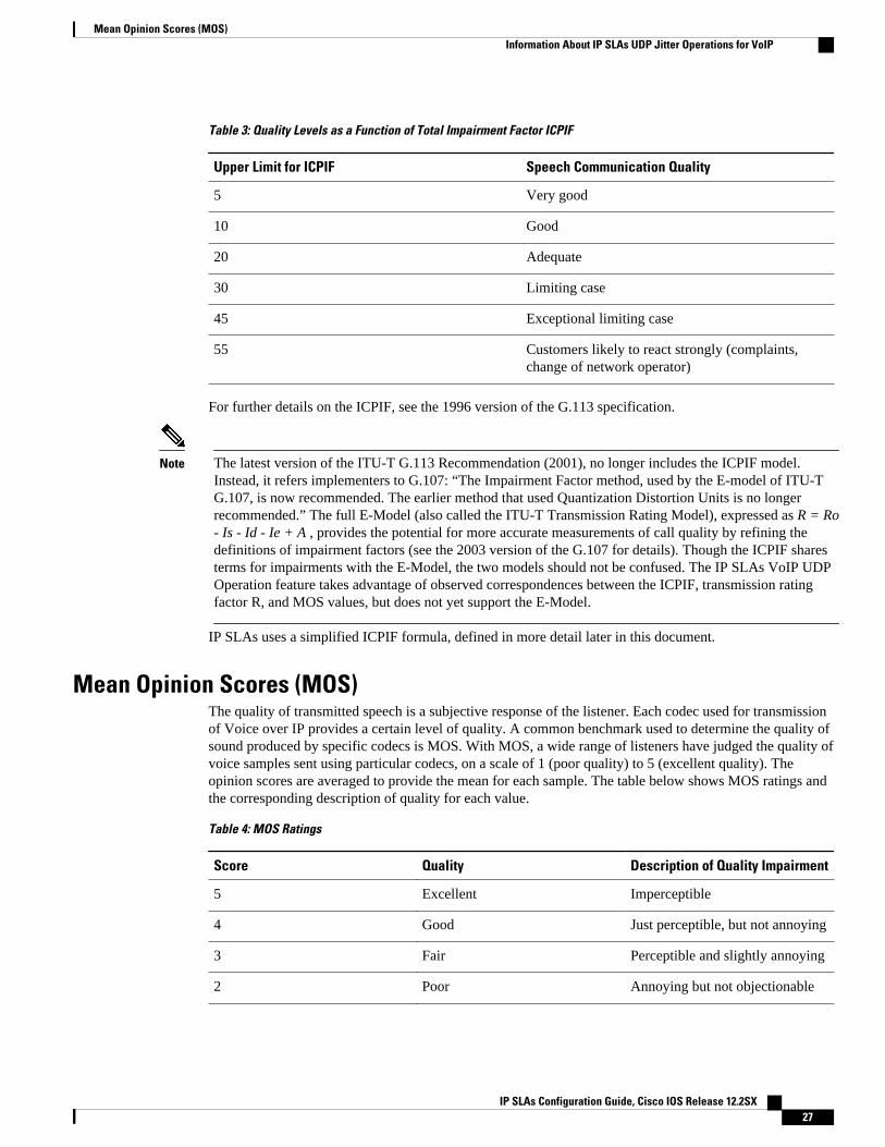
Table 3: Quality Levels as a Function of Total Impairment Factor ICPIF
Upper Limit for ICPIF Speech Communication Quality
5 Very good
10 Good
20 Adequate
30 Limiting case
45 Exceptional limiting case
55 Customers likely to react strongly (complaints,change of network operator)
For further details on the ICPIF, see the 1996 version of the G.113 specification.
Note The latest version of the ITU-T G.113 Recommendation (2001), no longer includes the ICPIF model.Instead, it refers implementers to G.107: “The Impairment Factor method, used by the E-model of ITU-TG.107, is now recommended. The earlier method that used Quantization Distortion Units is no longerrecommended.” The full E-Model (also called the ITU-T Transmission Rating Model), expressed as R = Ro- Is - Id - Ie + A , provides the potential for more accurate measurements of call quality by refining thedefinitions of impairment factors (see the 2003 version of the G.107 for details). Though the ICPIF sharesterms for impairments with the E-Model, the two models should not be confused. The IP SLAs VoIP UDPOperation feature takes advantage of observed correspondences between the ICPIF, transmission ratingfactor R, and MOS values, but does not yet support the E-Model.
IP SLAs uses a simplified ICPIF formula, defined in more detail later in this document.
Mean Opinion Scores (MOS)The quality of transmitted speech is a subjective response of the listener. Each codec used for transmissionof Voice over IP provides a certain level of quality. A common benchmark used to determine the quality ofsound produced by specific codecs is MOS. With MOS, a wide range of listeners have judged the quality ofvoice samples sent using particular codecs, on a scale of 1 (poor quality) to 5 (excellent quality). Theopinion scores are averaged to provide the mean for each sample. The table below shows MOS ratings andthe corresponding description of quality for each value.
Table 4: MOS Ratings
Score Quality Description of Quality Impairment
5 Excellent Imperceptible
4 Good Just perceptible, but not annoying
3 Fair Perceptible and slightly annoying
2 Poor Annoying but not objectionable
Mean Opinion Scores (MOS)Information About IP SLAs UDP Jitter Operations for VoIP
IP SLAs Configuration Guide, Cisco IOS Release 12.2SX 27
Score Quality Description of Quality Impairment
1 Bad Very annoying and objectionable
As the MOS ratings for codecs and other transmission impairments are known, an estimated MOS can becomputed and displayed based on measured impairments. This estimated value is designated as MOS-CQE(Mean Opinion Score; Conversational Quality, Estimated) by the ITU in order to distinguish it fromobjective or subjective MOS values (see P.800.1 for details).
Voice Performance Monitoring Using IP SLAsOne of the key metrics in measuring voice and video quality over an IP network is jitter. Jitter is the nameused to indicate the variation in delay between arriving packets (inter-packet delay variance). Jitter affectsvoice quality by causing uneven gaps in the speech pattern of the person talking. Other key performanceparameters for voice and video transmission over IP networks include latency (delay) and packet loss. IPSLAs is an embedded active monitoring feature of Cisco software that provides a means for simulating andmeasuring these parameters in order to ensure your network is meeting or exceeding service-levelagreements with your users.
IP SLAs provides a UDP jitter operation, which consists of UDP probe packets sent across the networkfrom an origin device to a specific destination (called the operational target). This synthetic traffic is usedto record the amount of jitter for the connection, as well as the round-trip time, per-direction packet loss,and one-way delay time (one-way latency). (The term “synthetic traffic” indicates that the network traffic issimulated; that is, the traffic is generated by IP SLAs.) Data, in the form of collected statistics, can bedisplayed for multiple tests over a user-defined period of time, allowing you to see, for example, how thenetwork performs at different times of the day, or over the course of a week. The jitter probe has theadvantage of utilizing the IP SLAs Responder to provide minimal latency at the receiving end.
The IP SLAs VoIP UDP jitter operation modifies the standard UDP jitter operation by adding the capabilityto return MOS and ICPIF scores in the data collected by the operation, in addition to the metrics alreadygathered by the UDP jitter operation. This VoIP-specific implementation provides even more usefulinformation in determining the performance of your VoIP network, thereby improving your ability toperform network assessment, troubleshooting, and health monitoring.
Codec Simulation Within IP SLAsThe IP SLAs VoIP UDP jitter operation computes statistics by sending n UDP packets, each of size s, sent tmilliseconds apart, from a given source router to a given target router, at a given frequency f. The targetrouter must be running the IP SLAs Responder in order to process the probe operations.
To generate MOS and ICPIF scores, you specify the codec type used for the connection when configuringthe VoIP UDP jitter operation. Based on the type of codec you configure for the operation, the number ofpackets (n), the size of each payload (s), the inter-packet time interval (t), and the operational frequency (f)will be auto-configured with default values. (See the table below for specifics.) However, you are given theoption, if needed, to manually configure these parameters in the syntax of theudp-jitter command.
The table below shows the default parameters that are configured for the operation by codec.
Voice Performance Monitoring Using IP SLAs Information About IP SLAs UDP Jitter Operations for VoIP
IP SLAs Configuration Guide, Cisco IOS Release 12.2SX28
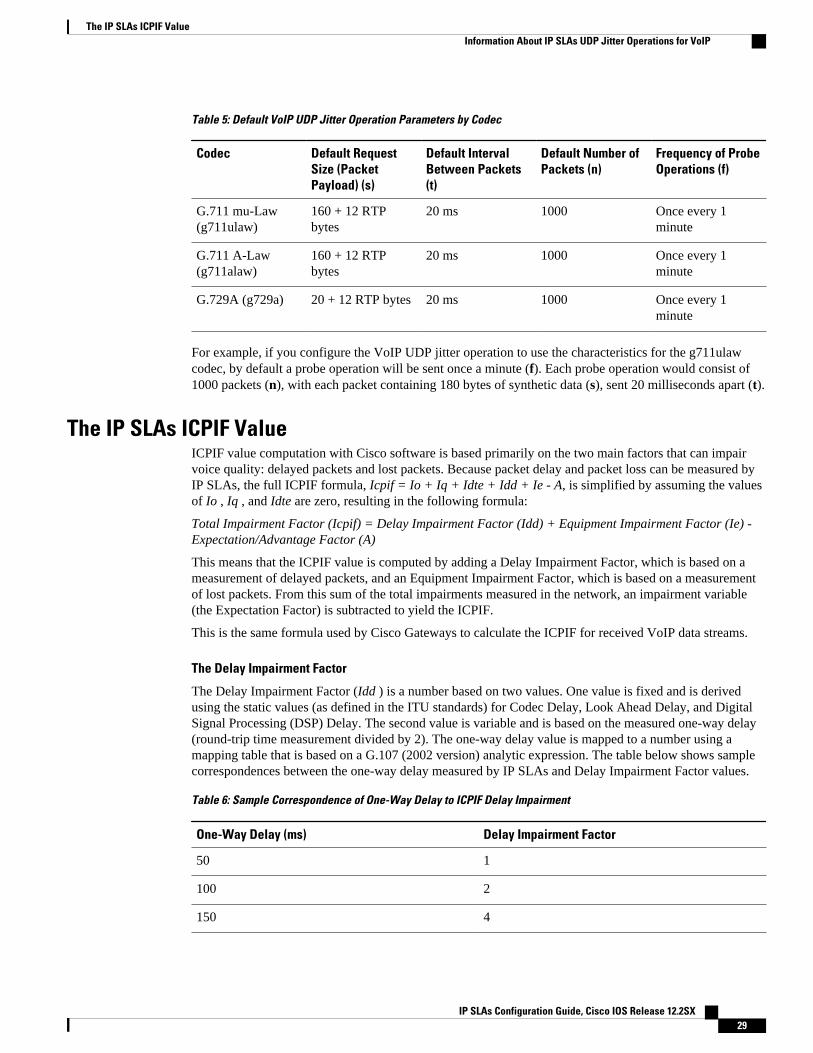
Table 5: Default VoIP UDP Jitter Operation Parameters by Codec
Codec Default RequestSize (PacketPayload) (s)
Default IntervalBetween Packets(t)
Default Number ofPackets (n)
Frequency of ProbeOperations (f)
G.711 mu-Law(g711ulaw)
160 + 12 RTPbytes
20 ms 1000 Once every 1minute
G.711 A-Law(g711alaw)
160 + 12 RTPbytes
20 ms 1000 Once every 1minute
G.729A (g729a) 20 + 12 RTP bytes 20 ms 1000 Once every 1minute
For example, if you configure the VoIP UDP jitter operation to use the characteristics for the g711ulawcodec, by default a probe operation will be sent once a minute (f). Each probe operation would consist of1000 packets (n), with each packet containing 180 bytes of synthetic data (s), sent 20 milliseconds apart (t).
The IP SLAs ICPIF ValueICPIF value computation with Cisco software is based primarily on the two main factors that can impairvoice quality: delayed packets and lost packets. Because packet delay and packet loss can be measured byIP SLAs, the full ICPIF formula, Icpif = Io + Iq + Idte + Idd + Ie - A, is simplified by assuming the valuesof Io , Iq , and Idte are zero, resulting in the following formula:
Total Impairment Factor (Icpif) = Delay Impairment Factor (Idd) + Equipment Impairment Factor (Ie) -Expectation/Advantage Factor (A)
This means that the ICPIF value is computed by adding a Delay Impairment Factor, which is based on ameasurement of delayed packets, and an Equipment Impairment Factor, which is based on a measurementof lost packets. From this sum of the total impairments measured in the network, an impairment variable(the Expectation Factor) is subtracted to yield the ICPIF.
This is the same formula used by Cisco Gateways to calculate the ICPIF for received VoIP data streams.
The Delay Impairment Factor
The Delay Impairment Factor (Idd ) is a number based on two values. One value is fixed and is derivedusing the static values (as defined in the ITU standards) for Codec Delay, Look Ahead Delay, and DigitalSignal Processing (DSP) Delay. The second value is variable and is based on the measured one-way delay(round-trip time measurement divided by 2). The one-way delay value is mapped to a number using amapping table that is based on a G.107 (2002 version) analytic expression. The table below shows samplecorrespondences between the one-way delay measured by IP SLAs and Delay Impairment Factor values.
Table 6: Sample Correspondence of One-Way Delay to ICPIF Delay Impairment
One-Way Delay (ms) Delay Impairment Factor
50 1
100 2
150 4
The IP SLAs ICPIF ValueInformation About IP SLAs UDP Jitter Operations for VoIP
IP SLAs Configuration Guide, Cisco IOS Release 12.2SX 29
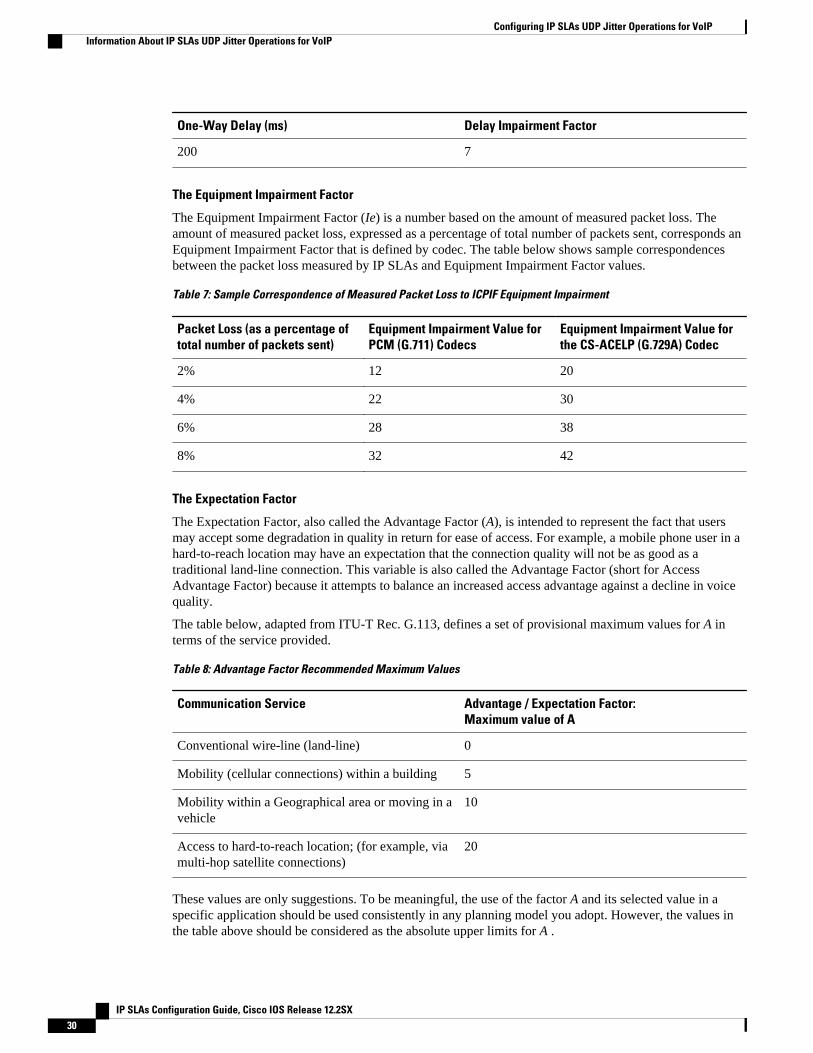
One-Way Delay (ms) Delay Impairment Factor
200 7
The Equipment Impairment Factor
The Equipment Impairment Factor (Ie) is a number based on the amount of measured packet loss. Theamount of measured packet loss, expressed as a percentage of total number of packets sent, corresponds anEquipment Impairment Factor that is defined by codec. The table below shows sample correspondencesbetween the packet loss measured by IP SLAs and Equipment Impairment Factor values.
Table 7: Sample Correspondence of Measured Packet Loss to ICPIF Equipment Impairment
Packet Loss (as a percentage oftotal number of packets sent)
Equipment Impairment Value forPCM (G.711) Codecs
Equipment Impairment Value forthe CS-ACELP (G.729A) Codec
2% 12 20
4% 22 30
6% 28 38
8% 32 42
The Expectation Factor
The Expectation Factor, also called the Advantage Factor (A), is intended to represent the fact that usersmay accept some degradation in quality in return for ease of access. For example, a mobile phone user in ahard-to-reach location may have an expectation that the connection quality will not be as good as atraditional land-line connection. This variable is also called the Advantage Factor (short for AccessAdvantage Factor) because it attempts to balance an increased access advantage against a decline in voicequality.
The table below, adapted from ITU-T Rec. G.113, defines a set of provisional maximum values for A interms of the service provided.
Table 8: Advantage Factor Recommended Maximum Values
Communication Service Advantage / Expectation Factor:Maximum value of A
Conventional wire-line (land-line) 0
Mobility (cellular connections) within a building 5
Mobility within a Geographical area or moving in avehicle
10
Access to hard-to-reach location; (for example, viamulti-hop satellite connections)
20
These values are only suggestions. To be meaningful, the use of the factor A and its selected value in aspecific application should be used consistently in any planning model you adopt. However, the values inthe table above should be considered as the absolute upper limits for A .
Configuring IP SLAs UDP Jitter Operations for VoIP Information About IP SLAs UDP Jitter Operations for VoIP
IP SLAs Configuration Guide, Cisco IOS Release 12.2SX30
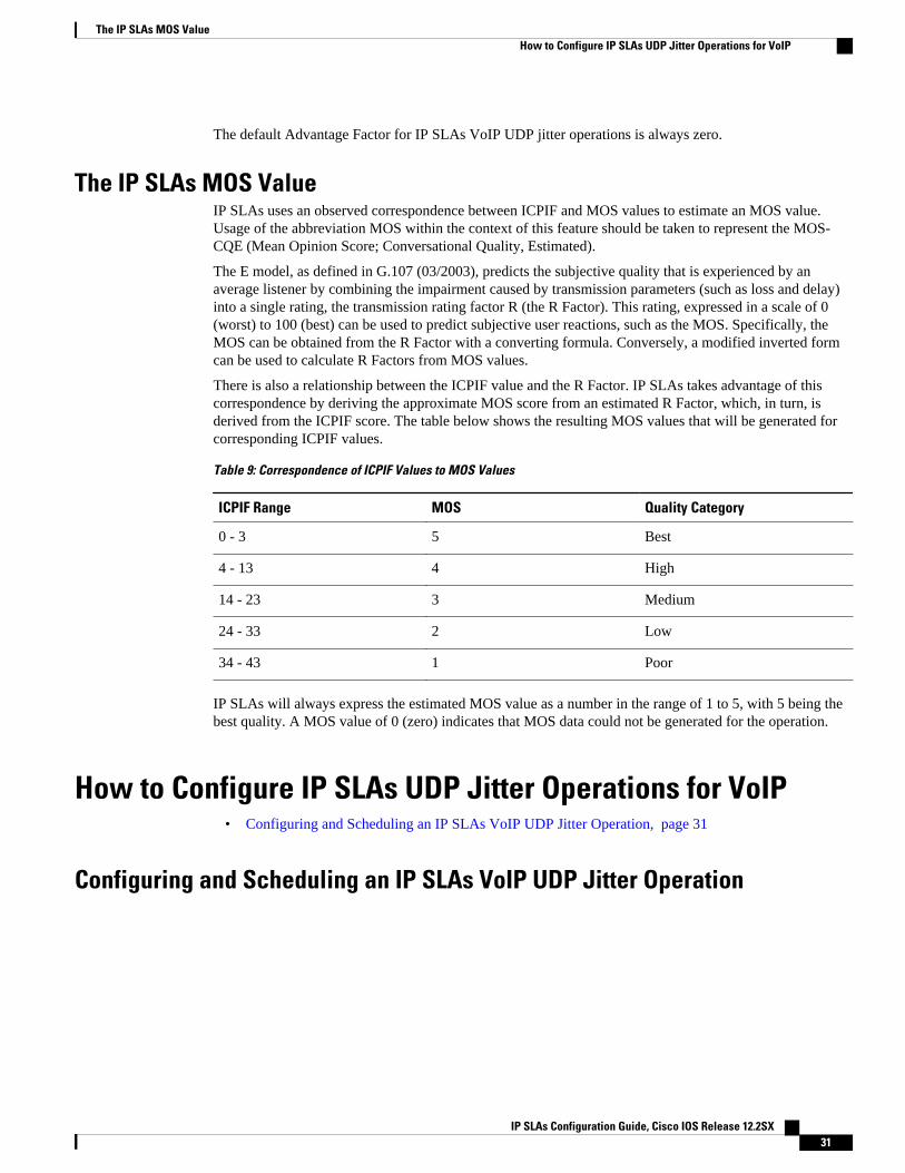
The default Advantage Factor for IP SLAs VoIP UDP jitter operations is always zero.
The IP SLAs MOS ValueIP SLAs uses an observed correspondence between ICPIF and MOS values to estimate an MOS value.Usage of the abbreviation MOS within the context of this feature should be taken to represent the MOS-CQE (Mean Opinion Score; Conversational Quality, Estimated).
The E model, as defined in G.107 (03/2003), predicts the subjective quality that is experienced by anaverage listener by combining the impairment caused by transmission parameters (such as loss and delay)into a single rating, the transmission rating factor R (the R Factor). This rating, expressed in a scale of 0(worst) to 100 (best) can be used to predict subjective user reactions, such as the MOS. Specifically, theMOS can be obtained from the R Factor with a converting formula. Conversely, a modified inverted formcan be used to calculate R Factors from MOS values.
There is also a relationship between the ICPIF value and the R Factor. IP SLAs takes advantage of thiscorrespondence by deriving the approximate MOS score from an estimated R Factor, which, in turn, isderived from the ICPIF score. The table below shows the resulting MOS values that will be generated forcorresponding ICPIF values.
Table 9: Correspondence of ICPIF Values to MOS Values
ICPIF Range MOS Quality Category
0 - 3 5 Best
4 - 13 4 High
14 - 23 3 Medium
24 - 33 2 Low
34 - 43 1 Poor
IP SLAs will always express the estimated MOS value as a number in the range of 1 to 5, with 5 being thebest quality. A MOS value of 0 (zero) indicates that MOS data could not be generated for the operation.
How to Configure IP SLAs UDP Jitter Operations for VoIP• Configuring and Scheduling an IP SLAs VoIP UDP Jitter Operation, page 31
Configuring and Scheduling an IP SLAs VoIP UDP Jitter Operation
The IP SLAs MOS ValueHow to Configure IP SLAs UDP Jitter Operations for VoIP
IP SLAs Configuration Guide, Cisco IOS Release 12.2SX 31
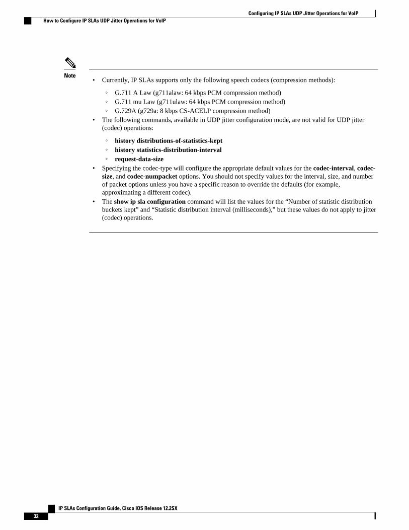
Note• Currently, IP SLAs supports only the following speech codecs (compression methods):
◦ G.711 A Law (g711alaw: 64 kbps PCM compression method)◦ G.711 mu Law (g711ulaw: 64 kbps PCM compression method)◦ G.729A (g729a: 8 kbps CS-ACELP compression method)
• The following commands, available in UDP jitter configuration mode, are not valid for UDP jitter(codec) operations:
◦ history distributions-of-statistics-kept◦ history statistics-distribution-interval◦ request-data-size
• Specifying the codec-type will configure the appropriate default values for the codec-interval, codec-size, and codec-numpacket options. You should not specify values for the interval, size, and numberof packet options unless you have a specific reason to override the defaults (for example,approximating a different codec).
• The show ip sla configuration command will list the values for the “Number of statistic distributionbuckets kept” and “Statistic distribution interval (milliseconds),” but these values do not apply to jitter(codec) operations.
Configuring IP SLAs UDP Jitter Operations for VoIP How to Configure IP SLAs UDP Jitter Operations for VoIP
IP SLAs Configuration Guide, Cisco IOS Release 12.2SX32
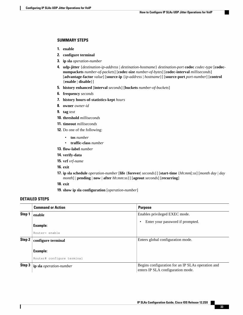
SUMMARY STEPS
1. enable
2. configure terminal
3. ip sla operation-number
4. udp-jitter {destination-ip-address | destination-hostname} destination-port codec codec-type [codec-numpackets number-of-packets] [codec-size number-of-bytes] [codec-interval milliseconds][advantage-factor value] [source-ip {ip-address | hostname}] [source-port port-number] [control{enable | disable}]
5. history enhanced [interval seconds] [buckets number-of-buckets]
6. frequency seconds
7. history hours-of-statistics-kept hours
8. owner owner-id
9. tag text
10. threshold milliseconds
11. timeout milliseconds
12. Do one of the following:
• tos number• traffic-class number
13. flow-label number
14. verify-data
15. vrf vrf-name
16. exit
17. ip sla schedule operation-number [life {forever| seconds}] [start-time {hh:mm[:ss] [month day | daymonth] | pending | now | after hh:mm:ss}] [ageout seconds] [recurring]
18. exit
19. show ip sla configuration [operation-number]
DETAILED STEPS
Command or Action Purpose
Step 1 enable
Example:
Router> enable
Enables privileged EXEC mode.
• Enter your password if prompted.
Step 2 configure terminal
Example:
Router# configure terminal
Enters global configuration mode.
Step 3 ip sla operation-number Begins configuration for an IP SLAs operation andenters IP SLA configuration mode.
Configuring IP SLAs UDP Jitter Operations for VoIPHow to Configure IP SLAs UDP Jitter Operations for VoIP
IP SLAs Configuration Guide, Cisco IOS Release 12.2SX 33
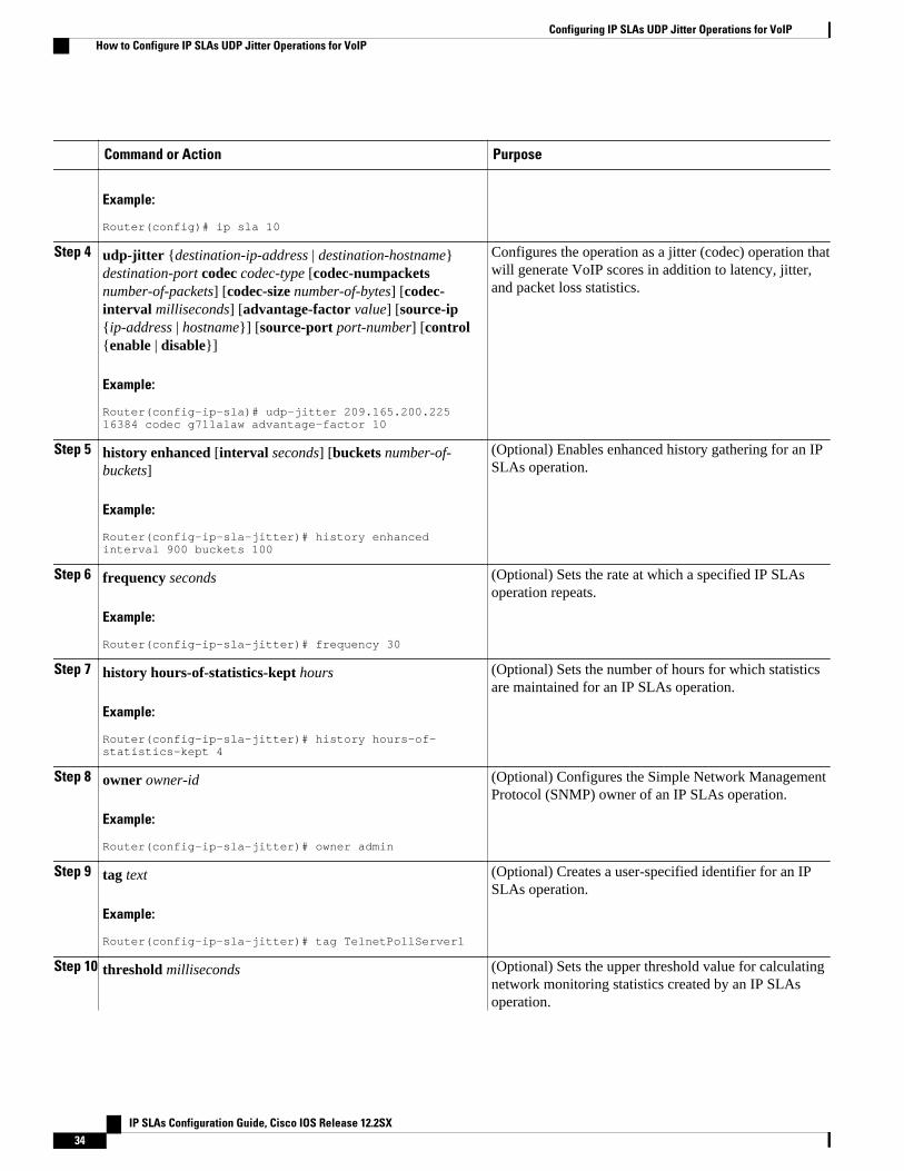
Command or Action Purpose
Example:
Router(config)# ip sla 10
Step 4 udp-jitter {destination-ip-address | destination-hostname}destination-port codec codec-type [codec-numpacketsnumber-of-packets] [codec-size number-of-bytes] [codec-interval milliseconds] [advantage-factor value] [source-ip{ip-address | hostname}] [source-port port-number] [control{enable | disable}]
Example:
Router(config-ip-sla)# udp-jitter 209.165.200.225 16384 codec g711alaw advantage-factor 10
Configures the operation as a jitter (codec) operation thatwill generate VoIP scores in addition to latency, jitter,and packet loss statistics.
Step 5 history enhanced [interval seconds] [buckets number-of-buckets]
Example:
Router(config-ip-sla-jitter)# history enhanced interval 900 buckets 100
(Optional) Enables enhanced history gathering for an IPSLAs operation.
Step 6 frequency seconds
Example:
Router(config-ip-sla-jitter)# frequency 30
(Optional) Sets the rate at which a specified IP SLAsoperation repeats.
Step 7 history hours-of-statistics-kept hours
Example:
Router(config-ip-sla-jitter)# history hours-of-statistics-kept 4
(Optional) Sets the number of hours for which statisticsare maintained for an IP SLAs operation.
Step 8 owner owner-id
Example:
Router(config-ip-sla-jitter)# owner admin
(Optional) Configures the Simple Network ManagementProtocol (SNMP) owner of an IP SLAs operation.
Step 9 tag text
Example:
Router(config-ip-sla-jitter)# tag TelnetPollServer1
(Optional) Creates a user-specified identifier for an IPSLAs operation.
Step 10 threshold milliseconds (Optional) Sets the upper threshold value for calculatingnetwork monitoring statistics created by an IP SLAsoperation.
Configuring IP SLAs UDP Jitter Operations for VoIP How to Configure IP SLAs UDP Jitter Operations for VoIP
IP SLAs Configuration Guide, Cisco IOS Release 12.2SX34
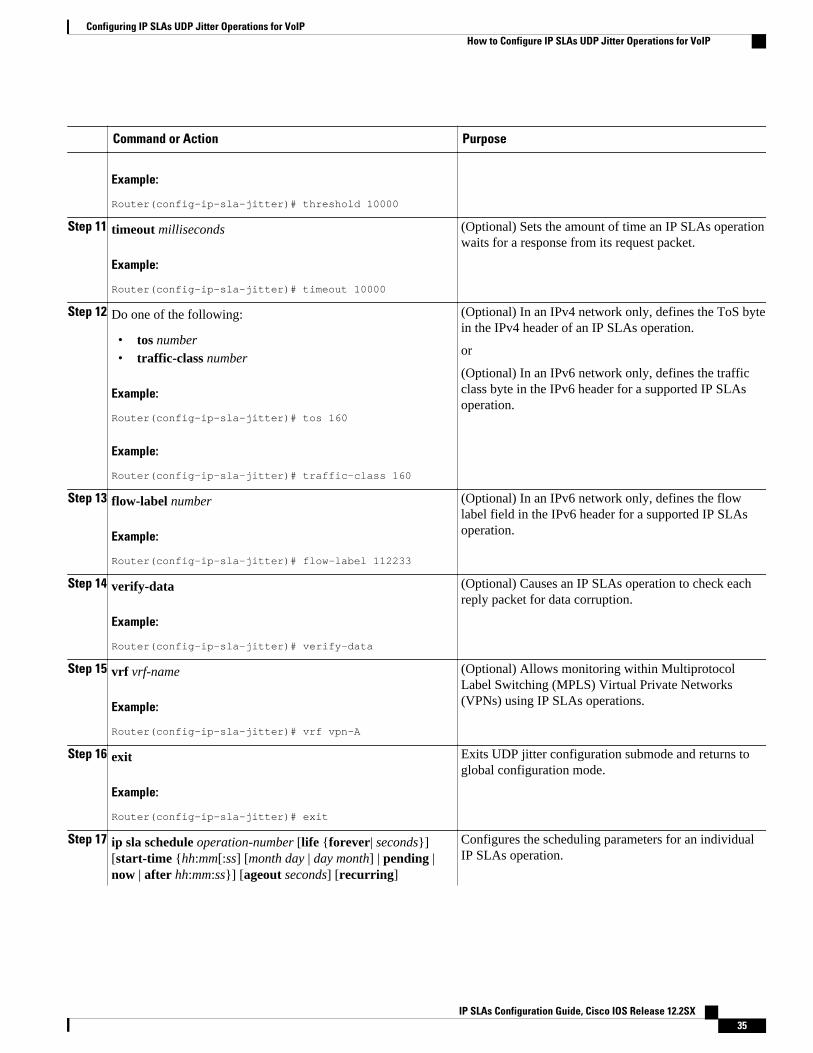
Command or Action Purpose
Example:
Router(config-ip-sla-jitter)# threshold 10000
Step 11 timeout milliseconds
Example:
Router(config-ip-sla-jitter)# timeout 10000
(Optional) Sets the amount of time an IP SLAs operationwaits for a response from its request packet.
Step 12 Do one of the following:
• tos number• traffic-class number
Example:
Router(config-ip-sla-jitter)# tos 160
Example:
Router(config-ip-sla-jitter)# traffic-class 160
(Optional) In an IPv4 network only, defines the ToS bytein the IPv4 header of an IP SLAs operation.
or
(Optional) In an IPv6 network only, defines the trafficclass byte in the IPv6 header for a supported IP SLAsoperation.
Step 13 flow-label number
Example:
Router(config-ip-sla-jitter)# flow-label 112233
(Optional) In an IPv6 network only, defines the flowlabel field in the IPv6 header for a supported IP SLAsoperation.
Step 14 verify-data
Example:
Router(config-ip-sla-jitter)# verify-data
(Optional) Causes an IP SLAs operation to check eachreply packet for data corruption.
Step 15 vrf vrf-name
Example:
Router(config-ip-sla-jitter)# vrf vpn-A
(Optional) Allows monitoring within MultiprotocolLabel Switching (MPLS) Virtual Private Networks(VPNs) using IP SLAs operations.
Step 16 exit
Example:
Router(config-ip-sla-jitter)# exit
Exits UDP jitter configuration submode and returns toglobal configuration mode.
Step 17 ip sla schedule operation-number [life {forever| seconds}][start-time {hh:mm[:ss] [month day | day month] | pending |now | after hh:mm:ss}] [ageout seconds] [recurring]
Configures the scheduling parameters for an individualIP SLAs operation.
Configuring IP SLAs UDP Jitter Operations for VoIPHow to Configure IP SLAs UDP Jitter Operations for VoIP
IP SLAs Configuration Guide, Cisco IOS Release 12.2SX 35
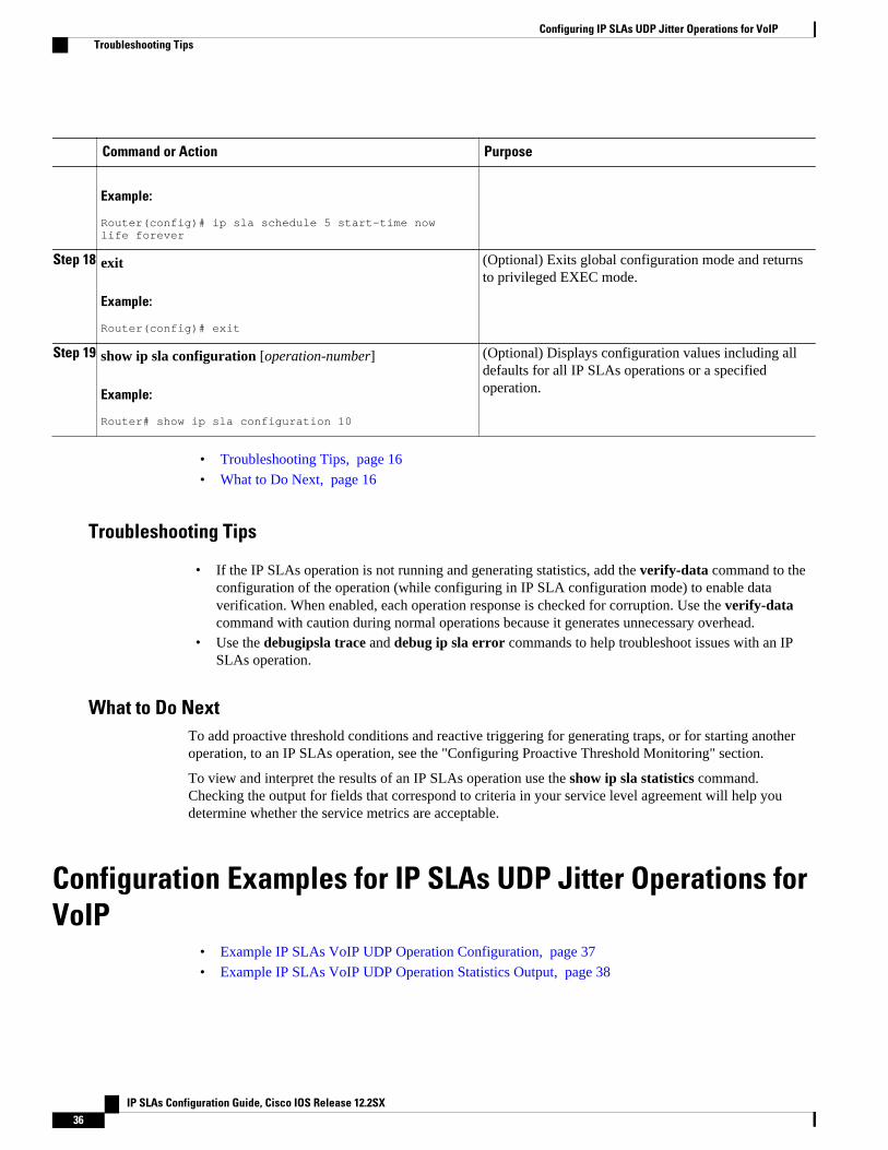
Command or Action Purpose
Example:
Router(config)# ip sla schedule 5 start-time now life forever
Step 18 exit
Example:
Router(config)# exit
(Optional) Exits global configuration mode and returnsto privileged EXEC mode.
Step 19 show ip sla configuration [operation-number]
Example:
Router# show ip sla configuration 10
(Optional) Displays configuration values including alldefaults for all IP SLAs operations or a specifiedoperation.
• Troubleshooting Tips, page 16
• What to Do Next, page 16
Troubleshooting Tips
• If the IP SLAs operation is not running and generating statistics, add the verify-data command to theconfiguration of the operation (while configuring in IP SLA configuration mode) to enable dataverification. When enabled, each operation response is checked for corruption. Use the verify-datacommand with caution during normal operations because it generates unnecessary overhead.
• Use the debugipsla trace and debug ip sla error commands to help troubleshoot issues with an IPSLAs operation.
What to Do NextTo add proactive threshold conditions and reactive triggering for generating traps, or for starting anotheroperation, to an IP SLAs operation, see the "Configuring Proactive Threshold Monitoring" section.
To view and interpret the results of an IP SLAs operation use the show ip sla statistics command.Checking the output for fields that correspond to criteria in your service level agreement will help youdetermine whether the service metrics are acceptable.
Configuration Examples for IP SLAs UDP Jitter Operations forVoIP
• Example IP SLAs VoIP UDP Operation Configuration, page 37
• Example IP SLAs VoIP UDP Operation Statistics Output, page 38
Configuring IP SLAs UDP Jitter Operations for VoIP Troubleshooting Tips
IP SLAs Configuration Guide, Cisco IOS Release 12.2SX36
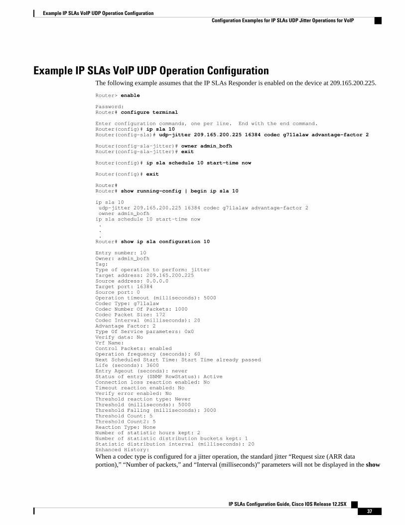
Example IP SLAs VoIP UDP Operation ConfigurationThe following example assumes that the IP SLAs Responder is enabled on the device at 209.165.200.225.
Router> enable Password: Router# configure terminal Enter configuration commands, one per line. End with the end command.Router(config)# ip sla 10 Router(config-sla)# udp-jitter 209.165.200.225 16384 codec g711alaw advantage-factor 2 Router(config-sla-jitter)# owner admin_bofhRouter(config-sla-jitter)# exit Router(config)# ip sla schedule 10 start-time now Router(config)# exit Router#Router# show running-config | begin ip sla 10 ip sla 10 udp-jitter 209.165.200.225 16384 codec g711alaw advantage-factor 2 owner admin_bofhip sla schedule 10 start-time now . . .Router# show ip sla configuration 10 Entry number: 10Owner: admin_bofhTag: Type of operation to perform: jitterTarget address: 209.165.200.225Source address: 0.0.0.0Target port: 16384Source port: 0Operation timeout (milliseconds): 5000Codec Type: g711alawCodec Number Of Packets: 1000Codec Packet Size: 172Codec Interval (milliseconds): 20Advantage Factor: 2Type Of Service parameters: 0x0Verify data: NoVrf Name: Control Packets: enabledOperation frequency (seconds): 60Next Scheduled Start Time: Start Time already passedLife (seconds): 3600Entry Ageout (seconds): neverStatus of entry (SNMP RowStatus): ActiveConnection loss reaction enabled: NoTimeout reaction enabled: NoVerify error enabled: NoThreshold reaction type: NeverThreshold (milliseconds): 5000Threshold Falling (milliseconds): 3000Threshold Count: 5Threshold Count2: 5Reaction Type: NoneNumber of statistic hours kept: 2Number of statistic distribution buckets kept: 1Statistic distribution interval (milliseconds): 20Enhanced History:
When a codec type is configured for a jitter operation, the standard jitter “Request size (ARR dataportion),” “Number of packets,” and “Interval (milliseconds)” parameters will not be displayed in the show
Example IP SLAs VoIP UDP Operation ConfigurationConfiguration Examples for IP SLAs UDP Jitter Operations for VoIP
IP SLAs Configuration Guide, Cisco IOS Release 12.2SX 37
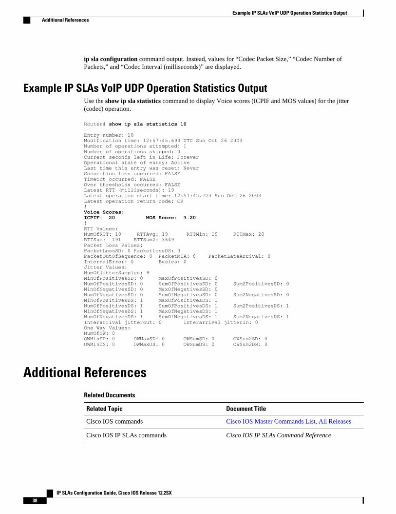
ip sla configuration command output. Instead, values for “Codec Packet Size,” “Codec Number ofPackets,” and “Codec Interval (milliseconds)” are displayed.
Example IP SLAs VoIP UDP Operation Statistics OutputUse the show ip sla statistics command to display Voice scores (ICPIF and MOS values) for the jitter(codec) operation.
Router# show ip sla statistics 10 Entry number: 10Modification time: 12:57:45.690 UTC Sun Oct 26 2003Number of operations attempted: 1Number of operations skipped: 0Current seconds left in Life: ForeverOperational state of entry: ActiveLast time this entry was reset: NeverConnection loss occurred: FALSETimeout occurred: FALSEOver thresholds occurred: FALSELatest RTT (milliseconds): 19Latest operation start time: 12:57:45.723 Sun Oct 26 2003Latest operation return code: OK!Voice Scores:ICPIF: 20 MOS Score: 3.20!RTT Values:NumOfRTT: 10 RTTAvg: 19 RTTMin: 19 RTTMax: 20RTTSum: 191 RTTSum2: 3649Packet Loss Values:PacketLossSD: 0 PacketLossDS: 0PacketOutOfSequence: 0 PacketMIA: 0 PacketLateArrival: 0InternalError: 0 Busies: 0Jitter Values:NumOfJitterSamples: 9MinOfPositivesSD: 0 MaxOfPositivesSD: 0NumOfPositivesSD: 0 SumOfPositivesSD: 0 Sum2PositivesSD: 0MinOfNegativesSD: 0 MaxOfNegativesSD: 0NumOfNegativesSD: 0 SumOfNegativesSD: 0 Sum2NegativesSD: 0MinOfPositivesDS: 1 MaxOfPositivesDS: 1NumOfPositivesDS: 1 SumOfPositivesDS: 1 Sum2PositivesDS: 1MinOfNegativesDS: 1 MaxOfNegativesDS: 1NumOfNegativesDS: 1 SumOfNegativesDS: 1 Sum2NegativesDS: 1Interarrival jitterout: 0 Interarrival jitterin: 0One Way Values:NumOfOW: 0OWMinSD: 0 OWMaxSD: 0 OWSumSD: 0 OWSum2SD: 0OWMinDS: 0 OWMaxDS: 0 OWSumDS: 0 OWSum2DS: 0
Additional ReferencesRelated Documents
Related Topic Document Title
Cisco IOS commands Cisco IOS Master Commands List, All Releases
Cisco IOS IP SLAs commands Cisco IOS IP SLAs Command Reference
Example IP SLAs VoIP UDP Operation Statistics Output Additional References
IP SLAs Configuration Guide, Cisco IOS Release 12.2SX38
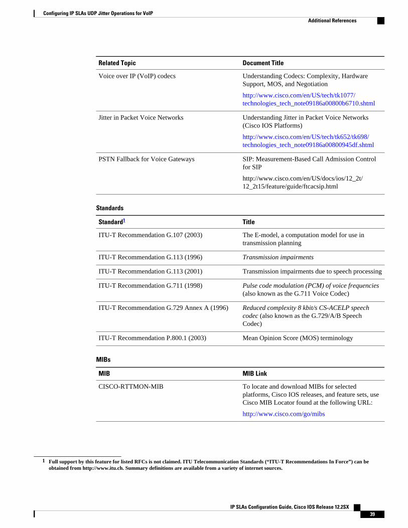
Related Topic Document Title
Voice over IP (VoIP) codecs Understanding Codecs: Complexity, HardwareSupport, MOS, and Negotiation
http://www.cisco.com/en/US/tech/tk1077/technologies_tech_note09186a00800b6710.shtml
Jitter in Packet Voice Networks Understanding Jitter in Packet Voice Networks(Cisco IOS Platforms)
http://www.cisco.com/en/US/tech/tk652/tk698/technologies_tech_note09186a00800945df.shtml
PSTN Fallback for Voice Gateways SIP: Measurement-Based Call Admission Controlfor SIP
http://www.cisco.com/en/US/docs/ios/12_2t/12_2t15/feature/guide/ftcacsip.html
Standards
Standard1 Title
ITU-T Recommendation G.107 (2003) The E-model, a computation model for use intransmission planning
ITU-T Recommendation G.113 (1996) Transmission impairments
ITU-T Recommendation G.113 (2001) Transmission impairments due to speech processing
ITU-T Recommendation G.711 (1998) Pulse code modulation (PCM) of voice frequencies(also known as the G.711 Voice Codec)
ITU-T Recommendation G.729 Annex A (1996) Reduced complexity 8 kbit/s CS-ACELP speechcodec (also known as the G.729/A/B SpeechCodec)
ITU-T Recommendation P.800.1 (2003) Mean Opinion Score (MOS) terminology
MIBs
MIB MIB Link
CISCO-RTTMON-MIB To locate and download MIBs for selectedplatforms, Cisco IOS releases, and feature sets, useCisco MIB Locator found at the following URL:
http://www.cisco.com/go/mibs
1 Full support by this feature for listed RFCs is not claimed. ITU Telecommunication Standards (“ITU-T Recommendations In Force”) can beobtained from http://www.itu.ch. Summary definitions are available from a variety of internet sources.
Configuring IP SLAs UDP Jitter Operations for VoIPAdditional References
IP SLAs Configuration Guide, Cisco IOS Release 12.2SX 39
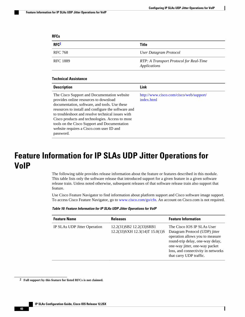
RFCs
RFC2 Title
RFC 768 User Datagram Protocol
RFC 1889 RTP: A Transport Protocol for Real-TimeApplications
Technical Assistance
Description Link
The Cisco Support and Documentation websiteprovides online resources to downloaddocumentation, software, and tools. Use theseresources to install and configure the software andto troubleshoot and resolve technical issues withCisco products and technologies. Access to mosttools on the Cisco Support and Documentationwebsite requires a Cisco.com user ID andpassword.
http://www.cisco.com/cisco/web/support/index.html
Feature Information for IP SLAs UDP Jitter Operations forVoIP
The following table provides release information about the feature or features described in this module.This table lists only the software release that introduced support for a given feature in a given softwarerelease train. Unless noted otherwise, subsequent releases of that software release train also support thatfeature.
Use Cisco Feature Navigator to find information about platform support and Cisco software image support.To access Cisco Feature Navigator, go to www.cisco.com/go/cfn. An account on Cisco.com is not required.
Table 10: Feature Information for IP SLAs UDP Jitter Operations for VoIP
Feature Name Releases Feature Information
IP SLAs UDP Jitter Operation 12.2(31)SB2 12.2(33)SRB112.2(33)SXH 12.3(14)T 15.0(1)S
The Cisco IOS IP SLAs UserDatagram Protocol (UDP) jitteroperation allows you to measureround-trip delay, one-way delay,one-way jitter, one-way packetloss, and connectivity in networksthat carry UDP traffic.
2 Full support by this feature for listed RFCs is not claimed.
Configuring IP SLAs UDP Jitter Operations for VoIP Feature Information for IP SLAs UDP Jitter Operations for VoIP
IP SLAs Configuration Guide, Cisco IOS Release 12.2SX40
Feature Name Releases Feature Information
IPv6 - IP SLAs (UDP Jitter, UDPEcho, ICMP Echo, TCP Connect)
12.2(33)SRC 12.2(33)SB12.4(20)T
Support was added for operabilityin IPv6 networks.
Glossarycodec --In the context of IP Telephony, a codec is a compression and decompression algorithm used totransfer voice and video data more efficiently. Voice codec types are typically referred to using the ITUrecommendation number that defines the algorithm (for example, “G.711” instead of “PCM”).
CS-ACELP --The codec type defined in the reference documents G.729 and G.729A, Coding of speech at8 kbit/s using conjugate-structure algebraic-code-excited linear-prediction (CS-ACELP) .
ITU --The International Telecommunication Union. The ITU is an international organization within theUnited Nations System where governments and the private sector coordinate global telecom networks andservices. The ITU Telecommunication Standardization Sector (ITU-T), responsible for defining standards(Recommendations) covering all fields of telecommunications, is one of the three operational sectors of theITU. The ITU web site is at http://www.itu.int.
ITU-T --ITU Telecommunication Standardization Sector. The ITU-T is one of the three operational sectorsof the ITU, and is responsible for defining standards (called ITU-T Recommendations) covering all fieldsof telecommunications.
MOS-CQE (Mean Opinion Score; Conversational Quality, Estimated)--The score calculated by a networkplanning model which aims at predicting the quality in a conversational application situation. Estimates ofconversational quality carried out according to ITU-T Rec. G.107, when transformed to a mean opinionscore (MOS), give results in terms of MOS-CQE.3
PCM --The codec type defined in the reference document G.711, Pulse code modulation (PCM) of voicefrequencies .
Cisco and the Cisco Logo are trademarks of Cisco Systems, Inc. and/or its affiliates in the U.S. and othercountries. A listing of Cisco's trademarks can be found at www.cisco.com/go/trademarks. Third partytrademarks mentioned are the property of their respective owners. The use of the word partner does notimply a partnership relationship between Cisco and any other company. (1005R)
Any Internet Protocol (IP) addresses and phone numbers used in this document are not intended to beactual addresses and phone numbers. Any examples, command display output, network topology diagrams,and other figures included in the document are shown for illustrative purposes only. Any use of actual IPaddresses or phone numbers in illustrative content is unintentional and coincidental.
3 Definition from ITU-T Recommendation P.800.1. Used in accordance with the ITU Copyright and Disclaimer Notice.
Configuring IP SLAs UDP Jitter Operations for VoIPGlossary
IP SLAs Configuration Guide, Cisco IOS Release 12.2SX 41

Example IP SLAs VoIP UDP Operation Statistics Output
IP SLAs Configuration Guide, Cisco IOS Release 12.2SX42
Configuring IP SLAs LSP Health MonitorOperations
This module describes how to configure an IP Service Level Agreements (SLAs) label switched path(LSP) Health Monitor with LSP Discovery feature. LSP health monitors enable you to to proactivelymonitor Layer 3 Multiprotocol Label Switching (MPLS) Virtual Private Networks (VPNs). This featureprovides automated end-to-end verification in the control plane and data plane for all LSPs between theparticipating Provider Edge (PE) routers. This end-to-end (PE-to-PE router) approach ensures that LSPconnectivity is verified along the paths that customer traffic is sent. Consequently, customer-impactingnetwork connectivity issues that occur within the MPLS core will be detected by the LSP Health Monitor.Once configured, the LSP Health Monitor will automatically create and delete IP SLAs LSP ping or LSPtraceroute operations based on network topology.
• Finding Feature Information, page 43• Prerequisites for LSP Health Monitor Operations, page 43• Restrictions for LSP Health Monitor Operations, page 44• Information About LSP Health Monitor Operations, page 44• How to Configure LSP Health Monitor Operations, page 52• Configuration Examples for LSP Health Monitors, page 72• Additional References, page 79• Feature Information for LSP Health Monitor Operations, page 80
Finding Feature InformationYour software release may not support all the features documented in this module. For the latest featureinformation and caveats, see the release notes for your platform and software release. To find informationabout the features documented in this module, and to see a list of the releases in which each feature issupported, see the Feature Information Table at the end of this document.
Use Cisco Feature Navigator to find information about platform support and Cisco software image support.To access Cisco Feature Navigator, go to www.cisco.com/go/cfn. An account on Cisco.com is not required.
Prerequisites for LSP Health Monitor Operations
IP SLAs Configuration Guide, Cisco IOS Release 12.2SX 43
• The participating PE routers of an LSP Health Monitor operation must support the MPLS LSP pingfeature. It is recommended that the Provider (P) routers also support the MPLS LSP Ping feature inorder to obtain complete error reporting and diagnostics information.
• Ensure that the source PE router has enough memory to support the desired LSP Health Monitorfunctionality. Enabling the LSP discovery option can potentially have a significant impact on routermemory. If there is not enough memory available during the LSP discovery process, the process willgracefully terminate and an error message will be displayed.
Note The destination PE routers of an LSP Health Monitor operation do not require the IP SLAs Responder to beenabled.
Restrictions for LSP Health Monitor Operations• Once an LSP Health Monitor operation is started, its configuration parameters should not be changed
until the operation has ended. Changing the configuration parameters while the operation is activelyrunning could cause delays in obtaining network connectivity statistics.
Information About LSP Health Monitor Operations• Benefits of the LSP Health Monitor, page 44
• How the LSP Health Monitor Works, page 45
• Discovery of Neighboring PE Routers, page 46
• The LSP Discovery Process, page 47
• LSP Discovery Groups, page 48
• IP SLAs LSP Ping and LSP Traceroute Operations, page 50
• IP SLAs VCCV Operation, page 50
• Proactive Threshold Monitoring for the LSP Health Monitor, page 50
• Multioperation Scheduling for the LSP Health Monitor, page 51
Benefits of the LSP Health Monitor• End-to-end LSP connectivity measurements across equal-cost multipaths for determining network
availability or testing network connectivity in MPLS networks• Proactive threshold monitoring through SNMP trap notifications and syslog messages• Reduced network troubleshooting time for MPLS networks• Scalable network error detection using fast retry capability• Creation and deletion of IP SLAs operations based on network topology• Discovery of Border Gateway Protocol (BGP) next hop neighbors based on local VPN routing and
forwarding instances (VRFs) and global routing tables• Multioperation scheduling of IP SLAs operations• Pseudo-wire connectivity testing between MPLS network edges, with threshold violations and scalable
operation scheduling
Benefits of the LSP Health Monitor Restrictions for LSP Health Monitor Operations
IP SLAs Configuration Guide, Cisco IOS Release 12.2SX44
• Monitoring and SNMP trap alerts for round-trip time (RTT) threshold violations, connection loss, andcommand response timeouts
How the LSP Health Monitor WorksThe LSP Health Monitor feature provides the capability to proactively monitor Layer 3 MPLS VPNs. Thegeneral process for how the LSP Health Monitor works is as follows:
1 The user configures an LSP Health Monitor operation and the BGP next hop neighbor discoveryprocess is enabled.Configuring an LSP Health Monitor operation is similar to configuring a standard IP SLAs operation.To illustrate, all operation parameters for an LSP Health Monitor operation are configured after anidentification number for the operation is specified. However, unlike standard IP SLAs operations, theseconfigured parameters are then used as the base configuration for the individual IP SLAs LSP ping andLSP traceroute operations that will be created by the LSP Health Monitor. The LSP discovery processcan potentially have a significant impact on the memory and CPU of the source PE router. To preventunnecessary router performance issues, careful consideration should be taken when configuring theoperational and scheduling parameters of an LSP Health Monitor operation.
When the BGP next hop neighbor discovery process is enabled, a database of BGP next hop neighborsin use by any VRF associated with the source PE router is generated based on information from thelocal VRF and global routing tables. For more information about the BGP next hop neighbor discoveryprocess, see the "Discovery of Neighboring PE Routers" section.
Note By default, only a single path between the source and destination PE routers is discovered. If the LSPdiscovery option is enabled, the equal-cost multipaths between the source and destination PE routers arediscovered. For more information on how the LSP discovery process works, see the "LSP DiscoveryProcess" section.
2 The user configures proactive threshold monitoring parameters for the LSP Health Monitor operation.For more information about proactive threshold monitoring, see the "Proactive Threshold Monitoringfor the LSP Health Monitor" section.Depending on the proactive threshold monitoring configuration options chosen, SNMP trapnotifications or syslog messages are generated as threshold violations are met.
3 The user configures multioperation scheduling parameters for the LSP Health Monitor operation. Formore information about multioperation scheduling, see the "Multioperation Scheduling for the LSPHealth Monitor" section.Once the LSP Health Monitor operation is started, a single IP SLAs operation is automatically created(based on parameters configured in Step 1) for each applicable PE (BGP next hop) neighbor. The IPSLAs operations will measure network connectivity between the source PE router and the discovereddestination PE router. The start time and frequency of each measurement is based on the multioperationscheduling parameters defined by the user.
Addition and Deletion of IP SLAs Operations
The LSP Health Monitor receives periodic notifications about BGP next hop neighbors that have beenadded to or removed from a particular VPN. This information is stored in a queue maintained by the LSPHealth Monitor. Based on the information in the queue and user-specified time intervals, new IP SLAsoperations are automatically created for newly discovered PE routers and existing IP SLAs operations areautomatically deleted for any PE routers that are no longer valid. The automatic deletion of operations canbe disabled. However, disabling this function is not recommended because these operations would thenneed to be deleted manually.
How the LSP Health Monitor WorksInformation About LSP Health Monitor Operations
IP SLAs Configuration Guide, Cisco IOS Release 12.2SX 45
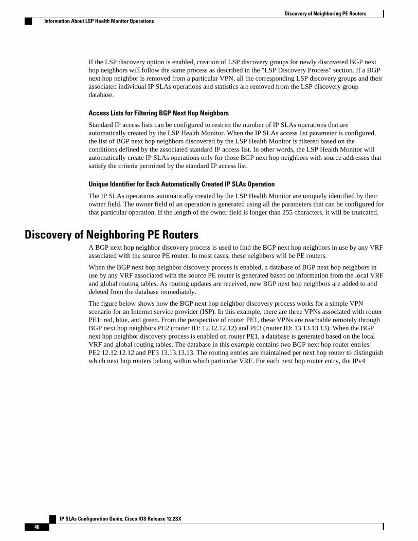
If the LSP discovery option is enabled, creation of LSP discovery groups for newly discovered BGP nexthop neighbors will follow the same process as described in the "LSP Discovery Process" section. If a BGPnext hop neighbor is removed from a particular VPN, all the corresponding LSP discovery groups and theirassociated individual IP SLAs operations and statistics are removed from the LSP discovery groupdatabase.
Access Lists for Filtering BGP Next Hop Neighbors
Standard IP access lists can be configured to restrict the number of IP SLAs operations that areautomatically created by the LSP Health Monitor. When the IP SLAs access list parameter is configured,the list of BGP next hop neighbors discovered by the LSP Health Monitor is filtered based on theconditions defined by the associated standard IP access list. In other words, the LSP Health Monitor willautomatically create IP SLAs operations only for those BGP next hop neighbors with source addresses thatsatisfy the criteria permitted by the standard IP access list.
Unique Identifier for Each Automatically Created IP SLAs Operation
The IP SLAs operations automatically created by the LSP Health Monitor are uniquely identified by theirowner field. The owner field of an operation is generated using all the parameters that can be configured forthat particular operation. If the length of the owner field is longer than 255 characters, it will be truncated.
Discovery of Neighboring PE RoutersA BGP next hop neighbor discovery process is used to find the BGP next hop neighbors in use by any VRFassociated with the source PE router. In most cases, these neighbors will be PE routers.
When the BGP next hop neighbor discovery process is enabled, a database of BGP next hop neighbors inuse by any VRF associated with the source PE router is generated based on information from the local VRFand global routing tables. As routing updates are received, new BGP next hop neighbors are added to anddeleted from the database immediately.
The figure below shows how the BGP next hop neighbor discovery process works for a simple VPNscenario for an Internet service provider (ISP). In this example, there are three VPNs associated with routerPE1: red, blue, and green. From the perspective of router PE1, these VPNs are reachable remotely throughBGP next hop neighbors PE2 (router ID: 12.12.12.12) and PE3 (router ID: 13.13.13.13). When the BGPnext hop neighbor discovery process is enabled on router PE1, a database is generated based on the localVRF and global routing tables. The database in this example contains two BGP next hop router entries:PE2 12.12.12.12 and PE3 13.13.13.13. The routing entries are maintained per next hop router to distinguishwhich next hop routers belong within which particular VRF. For each next hop router entry, the IPv4
Discovery of Neighboring PE Routers Information About LSP Health Monitor Operations
IP SLAs Configuration Guide, Cisco IOS Release 12.2SX46
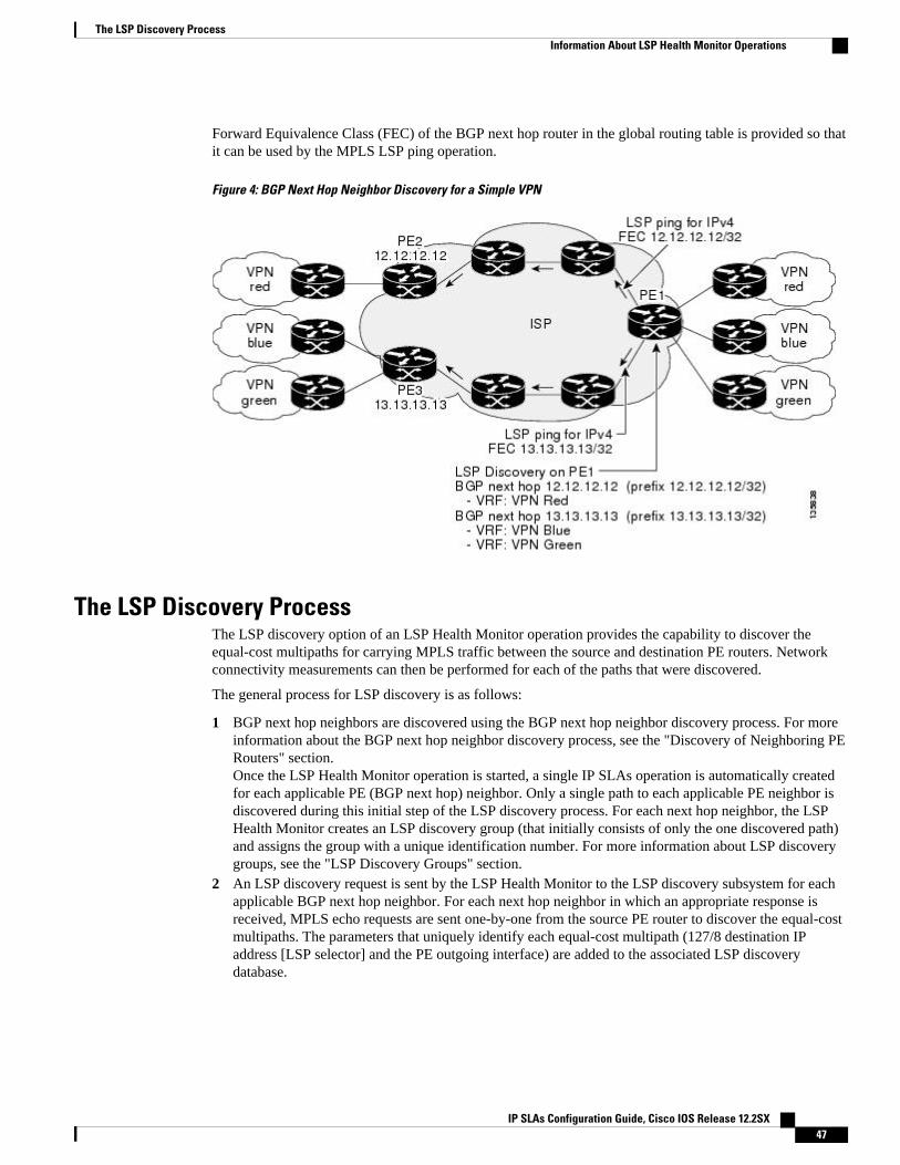
Forward Equivalence Class (FEC) of the BGP next hop router in the global routing table is provided so thatit can be used by the MPLS LSP ping operation.
Figure 4: BGP Next Hop Neighbor Discovery for a Simple VPN
The LSP Discovery ProcessThe LSP discovery option of an LSP Health Monitor operation provides the capability to discover theequal-cost multipaths for carrying MPLS traffic between the source and destination PE routers. Networkconnectivity measurements can then be performed for each of the paths that were discovered.
The general process for LSP discovery is as follows:
1 BGP next hop neighbors are discovered using the BGP next hop neighbor discovery process. For moreinformation about the BGP next hop neighbor discovery process, see the "Discovery of Neighboring PERouters" section.Once the LSP Health Monitor operation is started, a single IP SLAs operation is automatically createdfor each applicable PE (BGP next hop) neighbor. Only a single path to each applicable PE neighbor isdiscovered during this initial step of the LSP discovery process. For each next hop neighbor, the LSPHealth Monitor creates an LSP discovery group (that initially consists of only the one discovered path)and assigns the group with a unique identification number. For more information about LSP discoverygroups, see the "LSP Discovery Groups" section.
2 An LSP discovery request is sent by the LSP Health Monitor to the LSP discovery subsystem for eachapplicable BGP next hop neighbor. For each next hop neighbor in which an appropriate response isreceived, MPLS echo requests are sent one-by-one from the source PE router to discover the equal-costmultipaths. The parameters that uniquely identify each equal-cost multipath (127/8 destination IPaddress [LSP selector] and the PE outgoing interface) are added to the associated LSP discoverydatabase.
The LSP Discovery ProcessInformation About LSP Health Monitor Operations
IP SLAs Configuration Guide, Cisco IOS Release 12.2SX 47
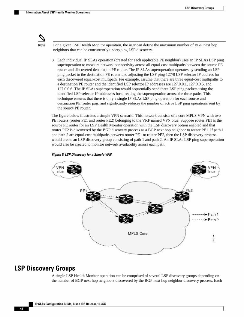
Note For a given LSP Health Monitor operation, the user can define the maximum number of BGP next hopneighbors that can be concurrently undergoing LSP discovery.
3 Each individual IP SLAs operation (created for each applicable PE neighbor) uses an IP SLAs LSP pingsuperoperation to measure network connectivity across all equal-cost multipaths between the source PErouter and discovered destination PE router. The IP SLAs superoperation operates by sending an LSPping packet to the destination PE router and adjusting the LSP ping 127/8 LSP selector IP address foreach discovered equal-cost multipath. For example, assume that there are three equal-cost multipaths toa destination PE router and the identified LSP selector IP addresses are 127.0.0.1, 127.0.0.5, and127.0.0.6. The IP SLAs superoperation would sequentially send three LSP ping packets using theidentified LSP selector IP addresses for directing the superoperation across the three paths. Thistechnique ensures that there is only a single IP SLAs LSP ping operation for each source anddestination PE router pair, and significantly reduces the number of active LSP ping operations sent bythe source PE router.
The figure below illustrates a simple VPN scenario. This network consists of a core MPLS VPN with twoPE routers (router PE1 and router PE2) belonging to the VRF named VPN blue. Suppose router PE1 is thesource PE router for an LSP Health Monitor operation with the LSP discovery option enabled and thatrouter PE2 is discovered by the BGP discovery process as a BGP next hop neighbor to router PE1. If path 1and path 2 are equal-cost multipaths between router PE1 to router PE2, then the LSP discovery processwould create an LSP discovery group consisting of path 1 and path 2. An IP SLAs LSP ping superoperationwould also be created to monitor network availability across each path.
Figure 5: LSP Discovery for a Simple VPN
LSP Discovery GroupsA single LSP Health Monitor operation can be comprised of several LSP discovery groups depending onthe number of BGP next hop neighbors discovered by the BGP next hop neighbor discovery process. Each
LSP Discovery Groups Information About LSP Health Monitor Operations
IP SLAs Configuration Guide, Cisco IOS Release 12.2SX48
LSP discovery group corresponds to one BGP next hop neighbor and is assigned a unique identificationnumber (starting with the number 1). The figure below illustrates a simple VPN scenario. This networkconsists of a core MPLS VPN with three PE routers (router PE1, PE2, and PE3) belonging to the VRFnamed VPN blue. Suppose router PE1 is the source PE router for an LSP Health Monitor operation with theLSP discovery option enabled and that router PE2 and PE3 are discovered by the BGP discovery process asBGP next hop neighbors to router PE1. LSP discovery group 1 is created for the equal-cost multipathsbetween router PE1 to router PE2 and LSP discovery group 2 is created for the equal-cost multipathsbetween router PE1 to router PE3.
Figure 6: LSP Discovery Groups for a Simple VPN
Once the LSP Health Monitor operation is started, a single IP SLAs operation is automatically created foreach applicable PE (BGP next hop) neighbor. Each IP SLAs operation (created for each applicable PEneighbor) uses an IP SLAs LSP ping superoperation to measure network connectivity across all equal-costmultipaths between the source PE router and discovered destination PE router. Each LSP pingsuperoperation corresponds to a single LSP discovery group.
The LSP ping superoperation operates by sending an LSP ping packet to the destination PE router andadjusting the LSP ping 127/8 LSP selector IP address for each discovered equal-cost multipath. Thenetwork connectivity statistics collected by each equal-cost multipath is aggregated and stored in one-hourincrements (data can be collected for a maximum of two hours). Results are stored as group averagesrepresentative of all the equal-cost multipaths within the LSP discovery group for a given one-hourincrement.
Each equal-cost multipath discovered between the source PE router and a BGP next hop neighbor isuniquely identified with the following parameters:
• 127/8 destination IP address (LSP selector) within the local host IP address range• PE outgoing interface
The database for an LSP discovery group is updated if any of the following events occur:
• The corresponding LSP ping superoperation sends an LSP ping packet.• An active equal-cost multipath is added to or deleted from the LSP discovery group.
Configuring IP SLAs LSP Health Monitor OperationsInformation About LSP Health Monitor Operations
IP SLAs Configuration Guide, Cisco IOS Release 12.2SX 49
• The user enters the Cisco command to delete all the aggregated statistical data for a particular LSPdiscovery group.
IP SLAs LSP Ping and LSP Traceroute OperationsThis feature introduces support for the IP SLAs LSP ping and IP SLAs LSP traceroute operations. Theseoperations are useful for troubleshooting network connectivity issues and determining network availabilityin an MPLS VPN. When using the LSP Health Monitor, IP SLAs LSP ping and LSP traceroute operationsare automatically created to measure network connectivity between the source PE router and the discovereddestination PE routers. Individual IP SLAs LSP ping and LSP traceroute operations can also be manuallyconfigured. Manual configuration of these operations can be useful for troubleshooting a connectivity issue.
The IP SLAs LSP ping and IP SLAs LSP traceroute operations are based on the same infrastructure usedby the MPLS LSP Ping and MPLS LSP Traceroute features, respectively, for sending and receiving echoreply and request packets to test LSPs.
The LSP discovery option does not support IP SLAs traceroute operations.
IP SLAs VCCV OperationThe IP SLAs VCCV operation supports Virtual Circuit Connectivity Verification (VCCV) for Pseudo-WireEmulation Edge-to-Edge (PWE3) services across MPLS networks. The IP SLAs VCCV operation type isbased on the ping mpls pseudowire command, which checks MPLS LSP connectivity across an AnyTransport over MPLS (AToM) virtual circuit (VC) by sending a series of pseudo-wire ping operations tothe specified destination PE router.
When MPLS LSP connectivity checking is performed through an IP SLAs VCCV operation (rather thanthrough the ping mpls command with the pseudowire keyword), you can use the IP SLA proactivethreshold monitoring and multioperation scheduling capabilities:
The LSP discovery option does not support the IP SLAs VCCV operation.
Proactive Threshold Monitoring for the LSP Health MonitorProactive threshold monitoring support for the LSP Health Monitor feature provides the capability fortriggering SNMP trap notifications and syslog messages when user-defined reaction conditions (such as aconnection loss or timeout) are met. Configuring threshold monitoring for an LSP Health Monitoroperation is similar to configuring threshold monitoring for a standard IP SLAs operation.
LSP Discovery Option Enabled
If the LSP discovery option for an LSP Health Monitor operation is enabled, SNMP trap notifications canbe generated when one of the following events occurs:
• LSP discovery for a particular BGP next hop neighbor fails.• Operational status of an LSP discovery group changes.
Possible reasons for which LSP discovery can fail for a particular BGP next hop neighbor are as follows:
• Expiration of time allowed for a BGP next hop neighbor to respond to an LSP discovery request.• Return code is “Broken” or “Unexplorable” for all paths leading to the BGP next hop neighbor.
The table below describes the conditions for which the operational status of an LSP discovery group canchange. Whenever an individual IP SLAs LSP ping operation of an LSP discovery group is executed, a
IP SLAs LSP Ping and LSP Traceroute Operations Information About LSP Health Monitor Operations
IP SLAs Configuration Guide, Cisco IOS Release 12.2SX50
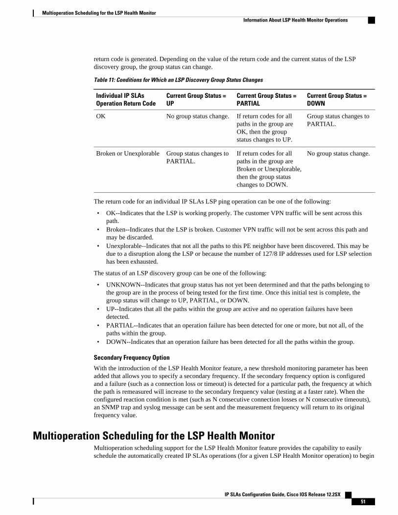
return code is generated. Depending on the value of the return code and the current status of the LSPdiscovery group, the group status can change.
Table 11: Conditions for Which an LSP Discovery Group Status Changes
Individual IP SLAsOperation Return Code
Current Group Status =UP
Current Group Status =PARTIAL
Current Group Status =DOWN
OK No group status change. If return codes for allpaths in the group areOK, then the groupstatus changes to UP.
Group status changes toPARTIAL.
Broken or Unexplorable Group status changes toPARTIAL.
If return codes for allpaths in the group areBroken or Unexplorable,then the group statuschanges to DOWN.
No group status change.
The return code for an individual IP SLAs LSP ping operation can be one of the following:
• OK--Indicates that the LSP is working properly. The customer VPN traffic will be sent across thispath.
• Broken--Indicates that the LSP is broken. Customer VPN traffic will not be sent across this path andmay be discarded.
• Unexplorable--Indicates that not all the paths to this PE neighbor have been discovered. This may bedue to a disruption along the LSP or because the number of 127/8 IP addresses used for LSP selectionhas been exhausted.
The status of an LSP discovery group can be one of the following:
• UNKNOWN--Indicates that group status has not yet been determined and that the paths belonging tothe group are in the process of being tested for the first time. Once this initial test is complete, thegroup status will change to UP, PARTIAL, or DOWN.
• UP--Indicates that all the paths within the group are active and no operation failures have beendetected.
• PARTIAL--Indicates that an operation failure has been detected for one or more, but not all, of thepaths within the group.
• DOWN--Indicates that an operation failure has been detected for all the paths within the group.
Secondary Frequency Option
With the introduction of the LSP Health Monitor feature, a new threshold monitoring parameter has beenadded that allows you to specify a secondary frequency. If the secondary frequency option is configuredand a failure (such as a connection loss or timeout) is detected for a particular path, the frequency at whichthe path is remeasured will increase to the secondary frequency value (testing at a faster rate). When theconfigured reaction condition is met (such as N consecutive connection losses or N consecutive timeouts),an SNMP trap and syslog message can be sent and the measurement frequency will return to its originalfrequency value.
Multioperation Scheduling for the LSP Health MonitorMultioperation scheduling support for the LSP Health Monitor feature provides the capability to easilyschedule the automatically created IP SLAs operations (for a given LSP Health Monitor operation) to begin
Multioperation Scheduling for the LSP Health MonitorInformation About LSP Health Monitor Operations
IP SLAs Configuration Guide, Cisco IOS Release 12.2SX 51
at intervals equally distributed over a specified duration of time (schedule period) and to restart at aspecified frequency. Multioperation scheduling is particularly useful in cases where the LSP HealthMonitor is enabled on a source PE router that has a large number of PE neighbors and, therefore, a largenumber of IP SLAs operations running at the same time.
Newly created IP SLAs operations (for newly discovered BGP next hop neighbors) are added to the sameschedule period as the operations that are currently running. To prevent too many operations from startingat the same time, the multioperation scheduling feature will schedule the operations to begin at randomintervals uniformly distributed over the schedule period.
Configuring a multioperation schedule for the LSP Health Monitor is similar to configuring a standardmultioperation schedule for a group of individual IP SLAs operations.
LSP Discovery Option Enabled
When a multioperation schedule for an LSP Health Monitor operation with LSP discovery is started, theBGP next hop neighbors are discovered, and network connectivity to each applicable neighbor is monitoredusing only a single LSP. In other words, initially, network connectivity between the source PE router anddiscovered destination PE router is measured across only a single path. This initial condition is the same asif an LSP Health Monitor operation was performed without LSP discovery.
Specific information about the IP SLAs LSP ping operations that are created for newly discovered equal-cost paths during the succeeding iterations of the LSP discovery process are stored in the LSP discoverygroup database. These newly created IP SLAs LSP ping operations will start collecting data at the nextiteration of network connectivity measurements for their associated LSP discovery group.
The start times for the individual IP SLAs LSP ping operations for each LSP discovery group is based onthe number of LSP discovery groups and the schedule period of the multioperation schedule. For example,if three LSP discovery groups (Group 1, Group 2, and Group 3) are scheduled to run over a period of 60seconds, the first LSP ping operation of Group 1 will start at 0 seconds, the first LSP ping operation ofGroup 2 will start at 20 seconds, and the first LSP ping operation of Group 3 will start at 40 seconds. Theremaining individual IP SLAs LSP ping operations for each LSP discovery group will run sequentially aftercompletion of the first LSP ping operation. For each LSP discovery group, only one LSP ping operationruns at a time.
How to Configure LSP Health Monitor Operations• Configuring an LSP Health Monitor Operation, page 52
• Scheduling LSP Health Monitor Operations, page 61
• Manually Configuring and Scheduling an IP SLAs LSP Ping or LSP Traceroute Operation, page 62
• Manually Configuring and Scheduling an IP SLAs VCCV Operation, page 66
• Verifying and Troubleshooting LSP Health Monitor Operations, page 70
Configuring an LSP Health Monitor OperationPerform only one of the following tasks:
• Configuring an LSP Health Monitor Operation without LSP Discovery on a PE Router, page 53
• Configuring the LSP Health Monitor Operation with LSP Discovery on a PE Router, page 57
Configuring an LSP Health Monitor Operation How to Configure LSP Health Monitor Operations
IP SLAs Configuration Guide, Cisco IOS Release 12.2SX52
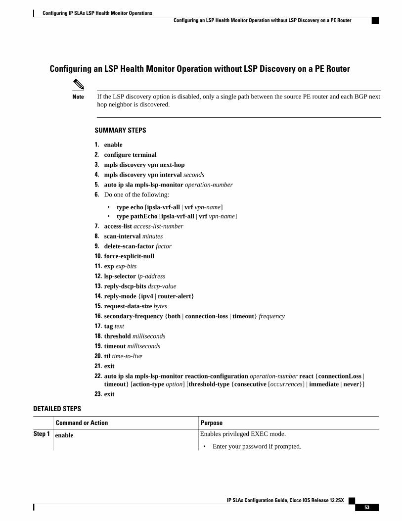
Configuring an LSP Health Monitor Operation without LSP Discovery on a PE Router
Note If the LSP discovery option is disabled, only a single path between the source PE router and each BGP nexthop neighbor is discovered.
SUMMARY STEPS
1. enable
2. configure terminal
3. mpls discovery vpn next-hop
4. mpls discovery vpn interval seconds
5. auto ip sla mpls-lsp-monitor operation-number
6. Do one of the following:
• type echo [ipsla-vrf-all | vrf vpn-name]• type pathEcho [ipsla-vrf-all | vrf vpn-name]
7. access-list access-list-number
8. scan-interval minutes
9. delete-scan-factor factor
10. force-explicit-null
11. exp exp-bits
12. lsp-selector ip-address
13. reply-dscp-bits dscp-value
14. reply-mode {ipv4 | router-alert}
15. request-data-size bytes
16. secondary-frequency {both | connection-loss | timeout} frequency
17. tag text
18. threshold milliseconds
19. timeout milliseconds
20. ttl time-to-live
21. exit
22. auto ip sla mpls-lsp-monitor reaction-configuration operation-number react {connectionLoss |timeout} [action-type option] [threshold-type {consecutive [occurrences] | immediate | never}]
23. exit
DETAILED STEPS
Command or Action Purpose
Step 1 enable Enables privileged EXEC mode.
• Enter your password if prompted.
Configuring IP SLAs LSP Health Monitor OperationsConfiguring an LSP Health Monitor Operation without LSP Discovery on a PE Router
IP SLAs Configuration Guide, Cisco IOS Release 12.2SX 53
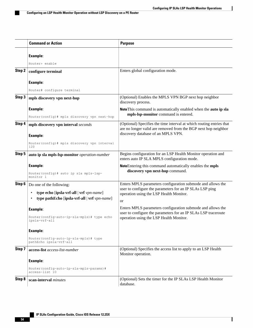
Command or Action Purpose
Example:
Router> enable
Step 2 configure terminal
Example:
Router# configure terminal
Enters global configuration mode.
Step 3 mpls discovery vpn next-hop
Example:
Router(config)# mpls discovery vpn next-hop
(Optional) Enables the MPLS VPN BGP next hop neighbordiscovery process.
NoteThis command is automatically enabled when the auto ip slampls-lsp-monitor command is entered.
Step 4 mpls discovery vpn interval seconds
Example:
Router(config)# mpls discovery vpn interval 120
(Optional) Specifies the time interval at which routing entries thatare no longer valid are removed from the BGP next hop neighbordiscovery database of an MPLS VPN.
Step 5 auto ip sla mpls-lsp-monitor operation-number
Example:
Router(config)# auto ip sla mpls-lsp-monitor 1
Begins configuration for an LSP Health Monitor operation andenters auto IP SLA MPLS configuration mode.
NoteEntering this command automatically enables the mplsdiscovery vpn next-hop command.
Step 6 Do one of the following:
• type echo [ipsla-vrf-all | vrf vpn-name]• type pathEcho [ipsla-vrf-all | vrf vpn-name]
Example:
Router(config-auto-ip-sla-mpls)# type echo ipsla-vrf-all
Example:
Router(config-auto-ip-sla-mpls)# type pathEcho ipsla-vrf-all
Enters MPLS parameters configuration submode and allows theuser to configure the parameters for an IP SLAs LSP pingoperation using the LSP Health Monitor.
or
Enters MPLS parameters configuration submode and allows theuser to configure the parameters for an IP SLAs LSP tracerouteoperation using the LSP Health Monitor.
Step 7 access-list access-list-number
Example:
Router(config-auto-ip-sla-mpls-params)# access-list 10
(Optional) Specifies the access list to apply to an LSP HealthMonitor operation.
Step 8 scan-interval minutes (Optional) Sets the timer for the IP SLAs LSP Health Monitordatabase.
Configuring IP SLAs LSP Health Monitor Operations Configuring an LSP Health Monitor Operation without LSP Discovery on a PE Router
IP SLAs Configuration Guide, Cisco IOS Release 12.2SX54
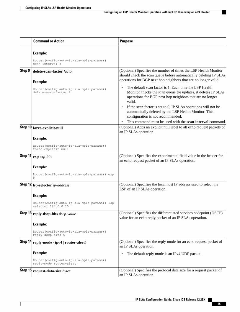
Command or Action Purpose
Example:
Router(config-auto-ip-sla-mpls-params)# scan-interval 5
Step 9 delete-scan-factor factor
Example:
Router(config-auto-ip-sla-mpls-params)# delete-scan-factor 2
(Optional) Specifies the number of times the LSP Health Monitorshould check the scan queue before automatically deleting IP SLAsoperations for BGP next hop neighbors that are no longer valid.
• The default scan factor is 1. Each time the LSP HealthMonitor checks the scan queue for updates, it deletes IP SLAsoperations for BGP next hop neighbors that are no longervalid.
• If the scan factor is set to 0, IP SLAs operations will not beautomatically deleted by the LSP Health Monitor. Thisconfiguration is not recommended.
• This command must be used with the scan-interval command.Step 10 force-explicit-null
Example:
Router(config-auto-ip-sla-mpls-params)# force-explicit-null
(Optional) Adds an explicit null label to all echo request packets ofan IP SLAs operation.
Step 11 exp exp-bits
Example:
Router(config-auto-ip-sla-mpls-params)# exp 5
(Optional) Specifies the experimental field value in the header foran echo request packet of an IP SLAs operation.
Step 12 lsp-selector ip-address
Example:
Router(config-auto-ip-sla-mpls-params)# lsp-selector 127.0.0.10
(Optional) Specifies the local host IP address used to select theLSP of an IP SLAs operation.
Step 13 reply-dscp-bits dscp-value
Example:
Router(config-auto-ip-sla-mpls-params)# reply-dscp-bits 5
(Optional) Specifies the differentiated services codepoint (DSCP)value for an echo reply packet of an IP SLAs operation.
Step 14 reply-mode {ipv4 | router-alert}
Example:
Router(config-auto-ip-sla-mpls-params)# reply-mode router-alert
(Optional) Specifies the reply mode for an echo request packet ofan IP SLAs operation.
• The default reply mode is an IPv4 UDP packet.
Step 15 request-data-size bytes (Optional) Specifies the protocol data size for a request packet ofan IP SLAs operation.
Configuring IP SLAs LSP Health Monitor OperationsConfiguring an LSP Health Monitor Operation without LSP Discovery on a PE Router
IP SLAs Configuration Guide, Cisco IOS Release 12.2SX 55
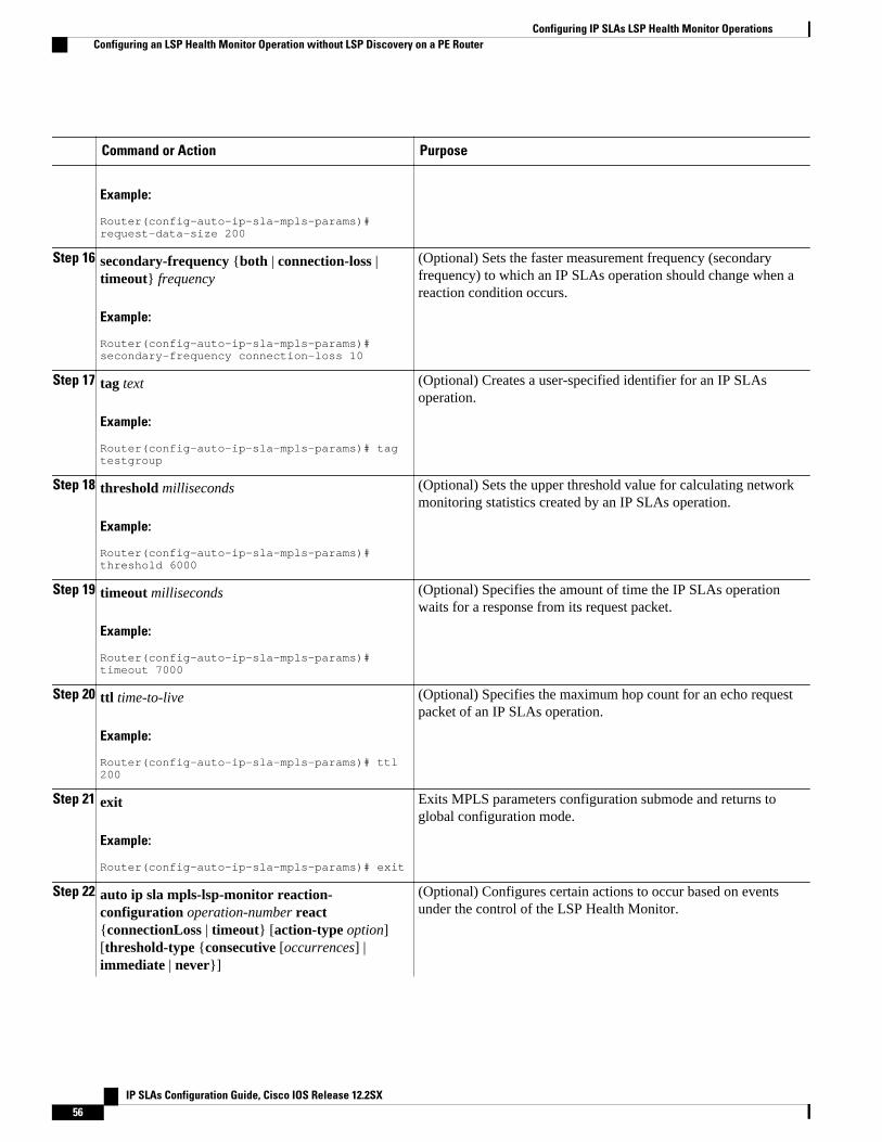
Command or Action Purpose
Example:
Router(config-auto-ip-sla-mpls-params)# request-data-size 200
Step 16 secondary-frequency {both | connection-loss |timeout} frequency
Example:
Router(config-auto-ip-sla-mpls-params)# secondary-frequency connection-loss 10
(Optional) Sets the faster measurement frequency (secondaryfrequency) to which an IP SLAs operation should change when areaction condition occurs.
Step 17 tag text
Example:
Router(config-auto-ip-sla-mpls-params)# tag testgroup
(Optional) Creates a user-specified identifier for an IP SLAsoperation.
Step 18 threshold milliseconds
Example:
Router(config-auto-ip-sla-mpls-params)# threshold 6000
(Optional) Sets the upper threshold value for calculating networkmonitoring statistics created by an IP SLAs operation.
Step 19 timeout milliseconds
Example:
Router(config-auto-ip-sla-mpls-params)# timeout 7000
(Optional) Specifies the amount of time the IP SLAs operationwaits for a response from its request packet.
Step 20 ttl time-to-live
Example:
Router(config-auto-ip-sla-mpls-params)# ttl 200
(Optional) Specifies the maximum hop count for an echo requestpacket of an IP SLAs operation.
Step 21 exit
Example:
Router(config-auto-ip-sla-mpls-params)# exit
Exits MPLS parameters configuration submode and returns toglobal configuration mode.
Step 22 auto ip sla mpls-lsp-monitor reaction-configuration operation-number react{connectionLoss | timeout} [action-type option][threshold-type {consecutive [occurrences] |immediate | never}]
(Optional) Configures certain actions to occur based on eventsunder the control of the LSP Health Monitor.
Configuring IP SLAs LSP Health Monitor Operations Configuring an LSP Health Monitor Operation without LSP Discovery on a PE Router
IP SLAs Configuration Guide, Cisco IOS Release 12.2SX56
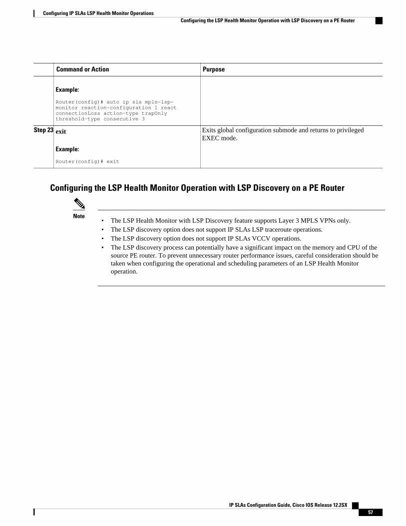
Command or Action Purpose
Example:
Router(config)# auto ip sla mpls-lsp-monitor reaction-configuration 1 react connectionLoss action-type trapOnly threshold-type consecutive 3
Step 23 exit
Example:
Router(config)# exit
Exits global configuration submode and returns to privilegedEXEC mode.
Configuring the LSP Health Monitor Operation with LSP Discovery on a PE Router
Note• The LSP Health Monitor with LSP Discovery feature supports Layer 3 MPLS VPNs only.• The LSP discovery option does not support IP SLAs LSP traceroute operations.• The LSP discovery option does not support IP SLAs VCCV operations.• The LSP discovery process can potentially have a significant impact on the memory and CPU of the
source PE router. To prevent unnecessary router performance issues, careful consideration should betaken when configuring the operational and scheduling parameters of an LSP Health Monitoroperation.
Configuring IP SLAs LSP Health Monitor OperationsConfiguring the LSP Health Monitor Operation with LSP Discovery on a PE Router
IP SLAs Configuration Guide, Cisco IOS Release 12.2SX 57
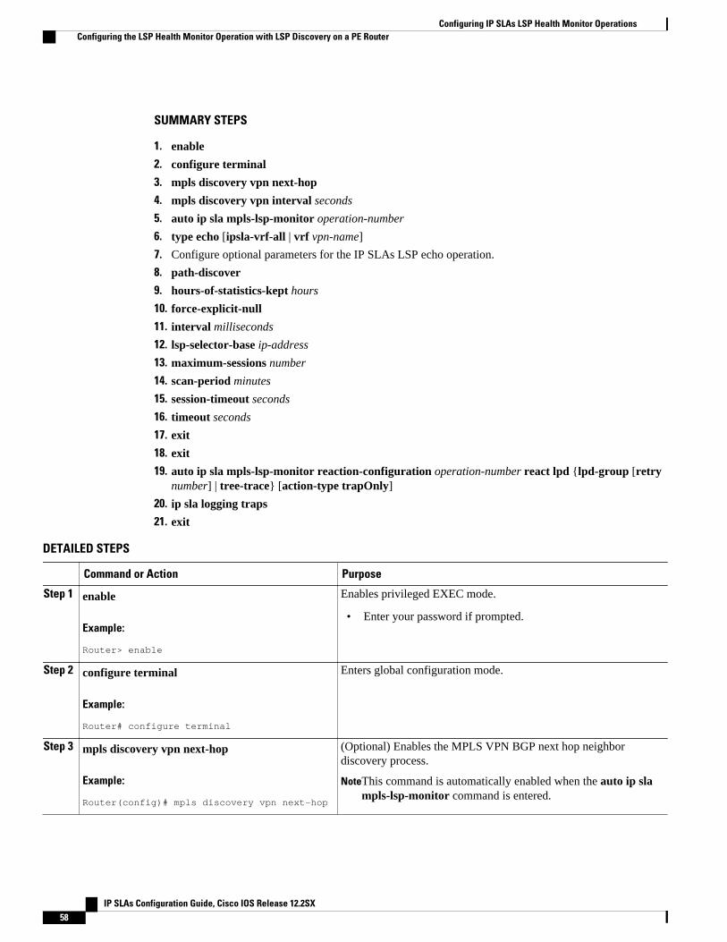
SUMMARY STEPS
1. enable
2. configure terminal
3. mpls discovery vpn next-hop
4. mpls discovery vpn interval seconds
5. auto ip sla mpls-lsp-monitor operation-number
6. type echo [ipsla-vrf-all | vrf vpn-name]
7. Configure optional parameters for the IP SLAs LSP echo operation.
8. path-discover
9. hours-of-statistics-kept hours
10. force-explicit-null
11. interval milliseconds
12. lsp-selector-base ip-address
13. maximum-sessions number
14. scan-period minutes
15. session-timeout seconds
16. timeout seconds
17. exit
18. exit
19. auto ip sla mpls-lsp-monitor reaction-configuration operation-number react lpd {lpd-group [retrynumber] | tree-trace} [action-type trapOnly]
20. ip sla logging traps
21. exit
DETAILED STEPS
Command or Action Purpose
Step 1 enable
Example:
Router> enable
Enables privileged EXEC mode.
• Enter your password if prompted.
Step 2 configure terminal
Example:
Router# configure terminal
Enters global configuration mode.
Step 3 mpls discovery vpn next-hop
Example:
Router(config)# mpls discovery vpn next-hop
(Optional) Enables the MPLS VPN BGP next hop neighbordiscovery process.
NoteThis command is automatically enabled when the auto ip slampls-lsp-monitor command is entered.
Configuring IP SLAs LSP Health Monitor Operations Configuring the LSP Health Monitor Operation with LSP Discovery on a PE Router
IP SLAs Configuration Guide, Cisco IOS Release 12.2SX58
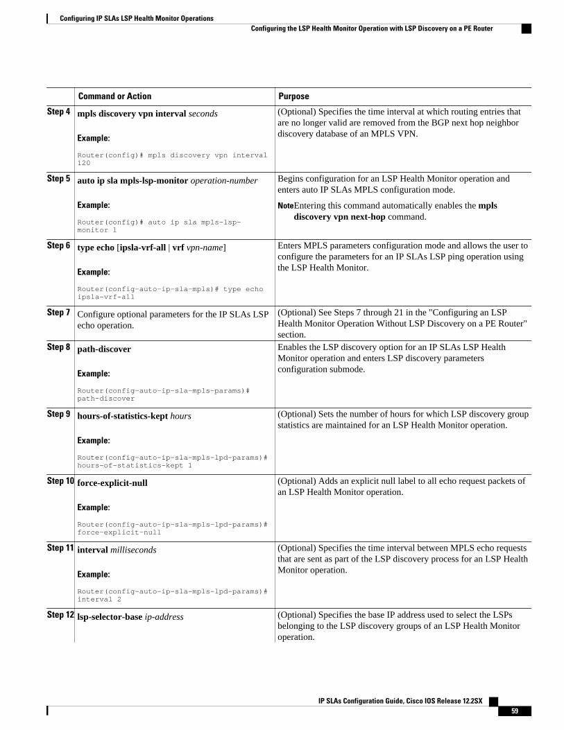
Command or Action Purpose
Step 4 mpls discovery vpn interval seconds
Example:
Router(config)# mpls discovery vpn interval 120
(Optional) Specifies the time interval at which routing entries thatare no longer valid are removed from the BGP next hop neighbordiscovery database of an MPLS VPN.
Step 5 auto ip sla mpls-lsp-monitor operation-number
Example:
Router(config)# auto ip sla mpls-lsp-monitor 1
Begins configuration for an LSP Health Monitor operation andenters auto IP SLAs MPLS configuration mode.
NoteEntering this command automatically enables the mplsdiscovery vpn next-hop command.
Step 6 type echo [ipsla-vrf-all | vrf vpn-name]
Example:
Router(config-auto-ip-sla-mpls)# type echo ipsla-vrf-all
Enters MPLS parameters configuration mode and allows the user toconfigure the parameters for an IP SLAs LSP ping operation usingthe LSP Health Monitor.
Step 7 Configure optional parameters for the IP SLAs LSPecho operation.
(Optional) See Steps 7 through 21 in the "Configuring an LSPHealth Monitor Operation Without LSP Discovery on a PE Router"section.
Step 8 path-discover
Example:
Router(config-auto-ip-sla-mpls-params)# path-discover
Enables the LSP discovery option for an IP SLAs LSP HealthMonitor operation and enters LSP discovery parametersconfiguration submode.
Step 9 hours-of-statistics-kept hours
Example:
Router(config-auto-ip-sla-mpls-lpd-params)# hours-of-statistics-kept 1
(Optional) Sets the number of hours for which LSP discovery groupstatistics are maintained for an LSP Health Monitor operation.
Step 10 force-explicit-null
Example:
Router(config-auto-ip-sla-mpls-lpd-params)# force-explicit-null
(Optional) Adds an explicit null label to all echo request packets ofan LSP Health Monitor operation.
Step 11 interval milliseconds
Example:
Router(config-auto-ip-sla-mpls-lpd-params)# interval 2
(Optional) Specifies the time interval between MPLS echo requeststhat are sent as part of the LSP discovery process for an LSP HealthMonitor operation.
Step 12 lsp-selector-base ip-address (Optional) Specifies the base IP address used to select the LSPsbelonging to the LSP discovery groups of an LSP Health Monitoroperation.
Configuring IP SLAs LSP Health Monitor OperationsConfiguring the LSP Health Monitor Operation with LSP Discovery on a PE Router
IP SLAs Configuration Guide, Cisco IOS Release 12.2SX 59
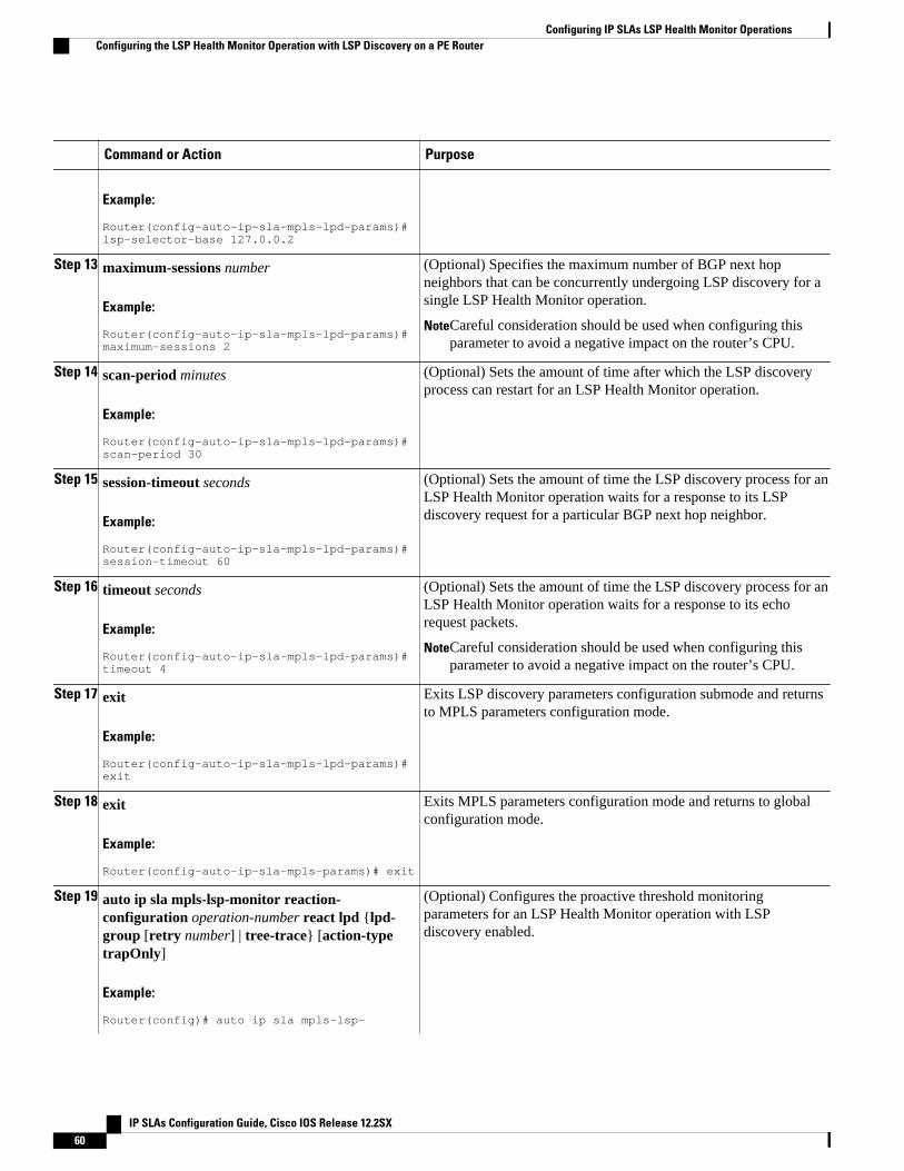
Command or Action Purpose
Example:
Router(config-auto-ip-sla-mpls-lpd-params)# lsp-selector-base 127.0.0.2
Step 13 maximum-sessions number
Example:
Router(config-auto-ip-sla-mpls-lpd-params)# maximum-sessions 2
(Optional) Specifies the maximum number of BGP next hopneighbors that can be concurrently undergoing LSP discovery for asingle LSP Health Monitor operation.
NoteCareful consideration should be used when configuring thisparameter to avoid a negative impact on the router’s CPU.
Step 14 scan-period minutes
Example:
Router(config-auto-ip-sla-mpls-lpd-params)# scan-period 30
(Optional) Sets the amount of time after which the LSP discoveryprocess can restart for an LSP Health Monitor operation.
Step 15 session-timeout seconds
Example:
Router(config-auto-ip-sla-mpls-lpd-params)# session-timeout 60
(Optional) Sets the amount of time the LSP discovery process for anLSP Health Monitor operation waits for a response to its LSPdiscovery request for a particular BGP next hop neighbor.
Step 16 timeout seconds
Example:
Router(config-auto-ip-sla-mpls-lpd-params)# timeout 4
(Optional) Sets the amount of time the LSP discovery process for anLSP Health Monitor operation waits for a response to its echorequest packets.
NoteCareful consideration should be used when configuring thisparameter to avoid a negative impact on the router’s CPU.
Step 17 exit
Example:
Router(config-auto-ip-sla-mpls-lpd-params)# exit
Exits LSP discovery parameters configuration submode and returnsto MPLS parameters configuration mode.
Step 18 exit
Example:
Router(config-auto-ip-sla-mpls-params)# exit
Exits MPLS parameters configuration mode and returns to globalconfiguration mode.
Step 19 auto ip sla mpls-lsp-monitor reaction-configuration operation-number react lpd {lpd-group [retry number] | tree-trace} [action-typetrapOnly]
Example:
Router(config)# auto ip sla mpls-lsp-
(Optional) Configures the proactive threshold monitoringparameters for an LSP Health Monitor operation with LSPdiscovery enabled.
Configuring IP SLAs LSP Health Monitor Operations Configuring the LSP Health Monitor Operation with LSP Discovery on a PE Router
IP SLAs Configuration Guide, Cisco IOS Release 12.2SX60
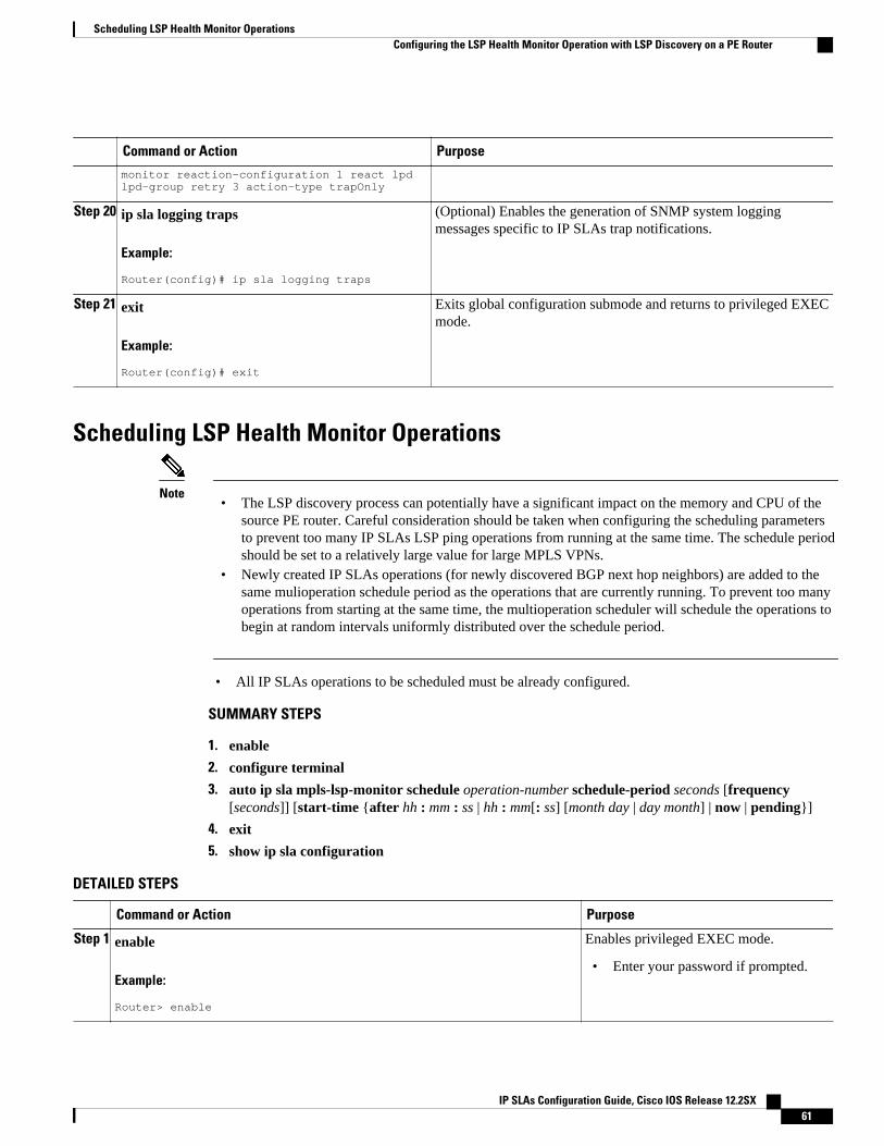
Command or Action Purposemonitor reaction-configuration 1 react lpd lpd-group retry 3 action-type trapOnly
Step 20 ip sla logging traps
Example:
Router(config)# ip sla logging traps
(Optional) Enables the generation of SNMP system loggingmessages specific to IP SLAs trap notifications.
Step 21 exit
Example:
Router(config)# exit
Exits global configuration submode and returns to privileged EXECmode.
Scheduling LSP Health Monitor Operations
Note• The LSP discovery process can potentially have a significant impact on the memory and CPU of the
source PE router. Careful consideration should be taken when configuring the scheduling parametersto prevent too many IP SLAs LSP ping operations from running at the same time. The schedule periodshould be set to a relatively large value for large MPLS VPNs.
• Newly created IP SLAs operations (for newly discovered BGP next hop neighbors) are added to thesame mulioperation schedule period as the operations that are currently running. To prevent too manyoperations from starting at the same time, the multioperation scheduler will schedule the operations tobegin at random intervals uniformly distributed over the schedule period.
• All IP SLAs operations to be scheduled must be already configured.
SUMMARY STEPS
1. enable
2. configure terminal
3. auto ip sla mpls-lsp-monitor schedule operation-number schedule-period seconds [frequency[seconds]] [start-time {after hh : mm : ss | hh : mm[: ss] [month day | day month] | now | pending}]
4. exit
5. show ip sla configuration
DETAILED STEPS
Command or Action Purpose
Step 1 enable
Example:
Router> enable
Enables privileged EXEC mode.
• Enter your password if prompted.
Scheduling LSP Health Monitor OperationsConfiguring the LSP Health Monitor Operation with LSP Discovery on a PE Router
IP SLAs Configuration Guide, Cisco IOS Release 12.2SX 61
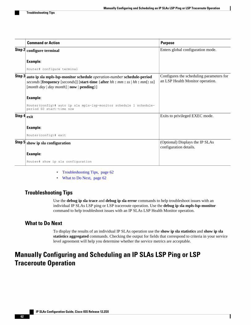
Command or Action Purpose
Step 2 configure terminal
Example:
Router# configure terminal
Enters global configuration mode.
Step 3 auto ip sla mpls-lsp-monitor schedule operation-number schedule-periodseconds [frequency [seconds]] [start-time {after hh : mm : ss | hh : mm[: ss][month day | day month] | now | pending}]
Example:
Router(config)# auto ip sla mpls-lsp-monitor schedule 1 schedule-period 60 start-time now
Configures the scheduling parameters foran LSP Health Monitor operation.
Step 4 exit
Example:
Router(config)# exit
Exits to privileged EXEC mode.
Step 5 show ip sla configuration
Example:
Router# show ip sla configuration
(Optional) Displays the IP SLAsconfiguration details.
• Troubleshooting Tips, page 62
• What to Do Next, page 62
Troubleshooting TipsUse the debug ip sla trace and debug ip sla error commands to help troubleshoot issues with anindividual IP SLAs LSP ping or LSP traceroute operation. Use the debug ip sla mpls-lsp-monitorcommand to help troubleshoot issues with an IP SLAs LSP Health Monitor operation.
What to Do NextTo display the results of an individual IP SLAs operation use the show ip sla statistics and show ip slastatistics aggregated commands. Checking the output for fields that correspond to criteria in your servicelevel agreement will help you determine whether the service metrics are acceptable.
Manually Configuring and Scheduling an IP SLAs LSP Ping or LSPTraceroute Operation
Manually Configuring and Scheduling an IP SLAs LSP Ping or LSP Traceroute Operation Troubleshooting Tips
IP SLAs Configuration Guide, Cisco IOS Release 12.2SX62
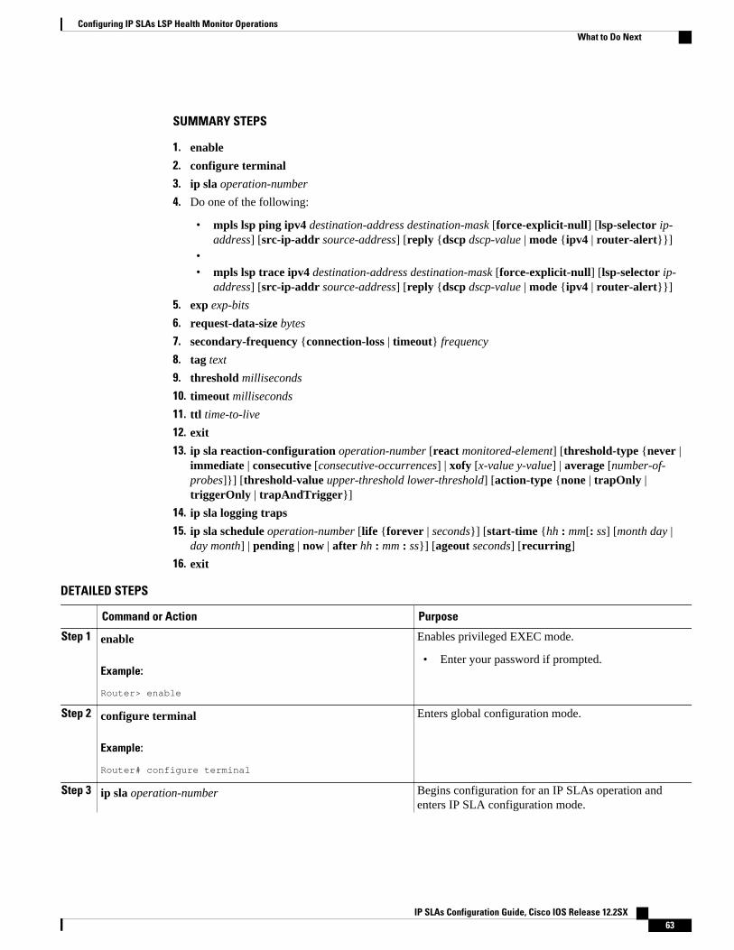
SUMMARY STEPS
1. enable
2. configure terminal
3. ip sla operation-number
4. Do one of the following:
• mpls lsp ping ipv4 destination-address destination-mask [force-explicit-null] [lsp-selector ip-address] [src-ip-addr source-address] [reply {dscp dscp-value | mode {ipv4 | router-alert}}]
•• mpls lsp trace ipv4 destination-address destination-mask [force-explicit-null] [lsp-selector ip-
address] [src-ip-addr source-address] [reply {dscp dscp-value | mode {ipv4 | router-alert}}]
5. exp exp-bits
6. request-data-size bytes
7. secondary-frequency {connection-loss | timeout} frequency
8. tag text
9. threshold milliseconds
10. timeout milliseconds
11. ttl time-to-live
12. exit
13. ip sla reaction-configuration operation-number [react monitored-element] [threshold-type {never |immediate | consecutive [consecutive-occurrences] | xofy [x-value y-value] | average [number-of-probes]}] [threshold-value upper-threshold lower-threshold] [action-type {none | trapOnly |triggerOnly | trapAndTrigger}]
14. ip sla logging traps
15. ip sla schedule operation-number [life {forever | seconds}] [start-time {hh : mm[: ss] [month day |day month] | pending | now | after hh : mm : ss}] [ageout seconds] [recurring]
16. exit
DETAILED STEPS
Command or Action Purpose
Step 1 enable
Example:
Router> enable
Enables privileged EXEC mode.
• Enter your password if prompted.
Step 2 configure terminal
Example:
Router# configure terminal
Enters global configuration mode.
Step 3 ip sla operation-number Begins configuration for an IP SLAs operation andenters IP SLA configuration mode.
Configuring IP SLAs LSP Health Monitor OperationsWhat to Do Next
IP SLAs Configuration Guide, Cisco IOS Release 12.2SX 63
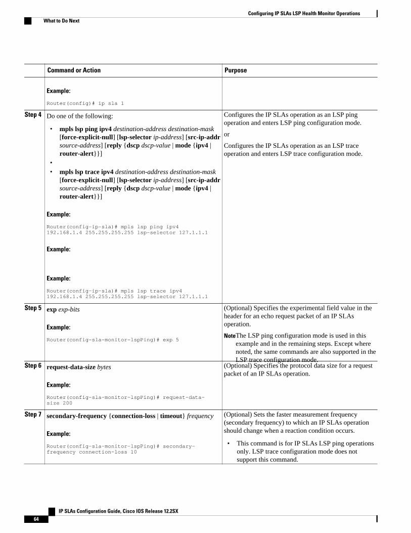
Command or Action Purpose
Example:
Router(config)# ip sla 1
Step 4 Do one of the following:
• mpls lsp ping ipv4 destination-address destination-mask[force-explicit-null] [lsp-selector ip-address] [src-ip-addrsource-address] [reply {dscp dscp-value | mode {ipv4 |router-alert}}]
•• mpls lsp trace ipv4 destination-address destination-mask
[force-explicit-null] [lsp-selector ip-address] [src-ip-addrsource-address] [reply {dscp dscp-value | mode {ipv4 |router-alert}}]
Example:
Router(config-ip-sla)# mpls lsp ping ipv4 192.168.1.4 255.255.255.255 lsp-selector 127.1.1.1
Example:
Example:
Router(config-ip-sla)# mpls lsp trace ipv4 192.168.1.4 255.255.255.255 lsp-selector 127.1.1.1
Configures the IP SLAs operation as an LSP pingoperation and enters LSP ping configuration mode.
or
Configures the IP SLAs operation as an LSP traceoperation and enters LSP trace configuration mode.
Step 5 exp exp-bits
Example:
Router(config-sla-monitor-lspPing)# exp 5
(Optional) Specifies the experimental field value in theheader for an echo request packet of an IP SLAsoperation.
NoteThe LSP ping configuration mode is used in thisexample and in the remaining steps. Except wherenoted, the same commands are also supported in theLSP trace configuration mode.
Step 6 request-data-size bytes
Example:
Router(config-sla-monitor-lspPing)# request-data-size 200
(Optional) Specifies the protocol data size for a requestpacket of an IP SLAs operation.
Step 7 secondary-frequency {connection-loss | timeout} frequency
Example:
Router(config-sla-monitor-lspPing)# secondary-frequency connection-loss 10
(Optional) Sets the faster measurement frequency(secondary frequency) to which an IP SLAs operationshould change when a reaction condition occurs.
• This command is for IP SLAs LSP ping operationsonly. LSP trace configuration mode does notsupport this command.
Configuring IP SLAs LSP Health Monitor Operations What to Do Next
IP SLAs Configuration Guide, Cisco IOS Release 12.2SX64
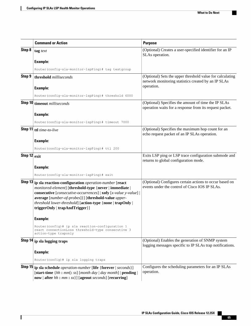
Command or Action Purpose
Step 8 tag text
Example:
Router(config-sla-monitor-lspPing)# tag testgroup
(Optional) Creates a user-specified identifier for an IPSLAs operation.
Step 9 threshold milliseconds
Example:
Router(config-sla-monitor-lspPing)# threshold 6000
(Optional) Sets the upper threshold value for calculatingnetwork monitoring statistics created by an IP SLAsoperation.
Step 10 timeout milliseconds
Example:
Router(config-sla-monitor-lspPing)# timeout 7000
(Optional) Specifies the amount of time the IP SLAsoperation waits for a response from its request packet.
Step 11 ttl time-to-live
Example:
Router(config-sla-monitor-lspPing)# ttl 200
(Optional) Specifies the maximum hop count for anecho request packet of an IP SLAs operation.
Step 12 exit
Example:
Router(config-sla-monitor-lspPing)# exit
Exits LSP ping or LSP trace configuration submode andreturns to global configuration mode.
Step 13 ip sla reaction-configuration operation-number [reactmonitored-element] [threshold-type {never | immediate |consecutive [consecutive-occurrences] | xofy [x-value y-value] |average [number-of-probes]}] [threshold-value upper-threshold lower-threshold] [action-type {none | trapOnly |triggerOnly | trapAndTrigger}]
Example:
Router(config)# ip sla reaction-configuration 1 react connectionLoss threshold-type consecutive 3 action-type traponly
(Optional) Configures certain actions to occur based onevents under the control of Cisco IOS IP SLAs.
Step 14 ip sla logging traps
Example:
Router(config)# ip sla logging traps
(Optional) Enables the generation of SNMP systemlogging messages specific to IP SLAs trap notifications.
Step 15 ip sla schedule operation-number [life {forever | seconds}][start-time {hh : mm[: ss] [month day | day month] | pending |now | after hh : mm : ss}] [ageout seconds] [recurring]
Configures the scheduling parameters for an IP SLAsoperation.
Configuring IP SLAs LSP Health Monitor OperationsWhat to Do Next
IP SLAs Configuration Guide, Cisco IOS Release 12.2SX 65
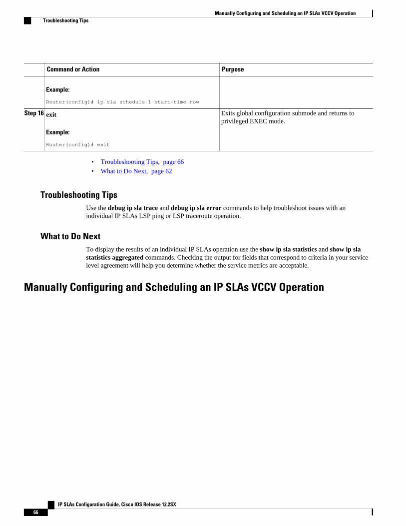
Command or Action Purpose
Example:
Router(config)# ip sla schedule 1 start-time now
Step 16 exit
Example:
Router(config)# exit
Exits global configuration submode and returns toprivileged EXEC mode.
• Troubleshooting Tips, page 66
• What to Do Next, page 62
Troubleshooting TipsUse the debug ip sla trace and debug ip sla error commands to help troubleshoot issues with anindividual IP SLAs LSP ping or LSP traceroute operation.
What to Do NextTo display the results of an individual IP SLAs operation use the show ip sla statistics and show ip slastatistics aggregated commands. Checking the output for fields that correspond to criteria in your servicelevel agreement will help you determine whether the service metrics are acceptable.
Manually Configuring and Scheduling an IP SLAs VCCV Operation
Manually Configuring and Scheduling an IP SLAs VCCV Operation Troubleshooting Tips
IP SLAs Configuration Guide, Cisco IOS Release 12.2SX66
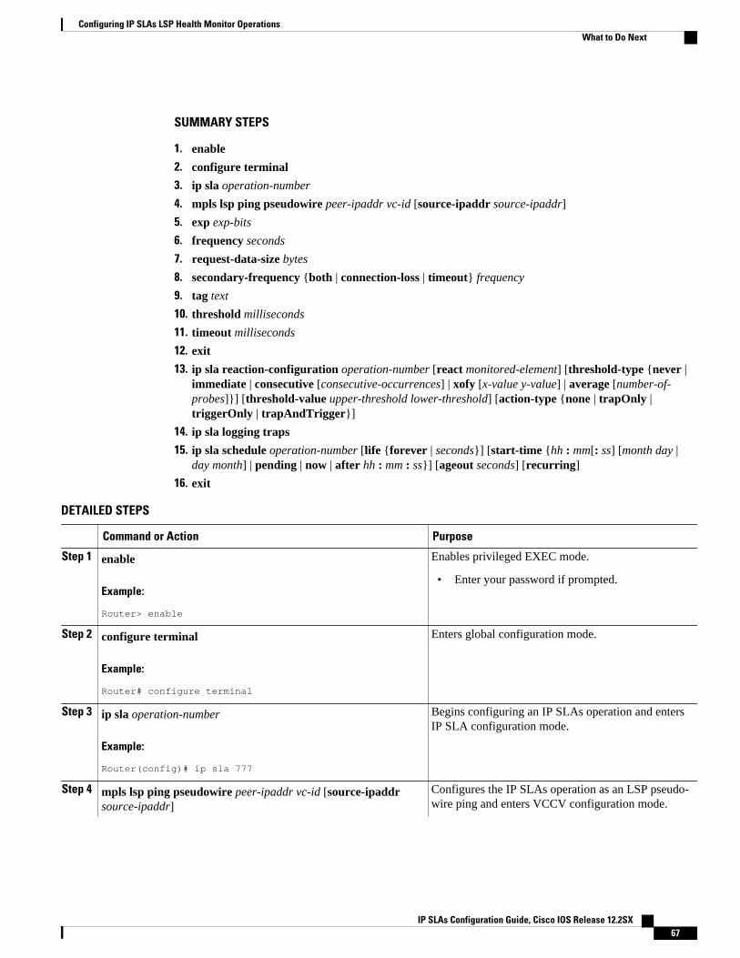
SUMMARY STEPS
1. enable
2. configure terminal
3. ip sla operation-number
4. mpls lsp ping pseudowire peer-ipaddr vc-id [source-ipaddr source-ipaddr]
5. exp exp-bits
6. frequency seconds
7. request-data-size bytes
8. secondary-frequency {both | connection-loss | timeout} frequency
9. tag text
10. threshold milliseconds
11. timeout milliseconds
12. exit
13. ip sla reaction-configuration operation-number [react monitored-element] [threshold-type {never |immediate | consecutive [consecutive-occurrences] | xofy [x-value y-value] | average [number-of-probes]}] [threshold-value upper-threshold lower-threshold] [action-type {none | trapOnly |triggerOnly | trapAndTrigger}]
14. ip sla logging traps
15. ip sla schedule operation-number [life {forever | seconds}] [start-time {hh : mm[: ss] [month day |day month] | pending | now | after hh : mm : ss}] [ageout seconds] [recurring]
16. exit
DETAILED STEPS
Command or Action Purpose
Step 1 enable
Example:
Router> enable
Enables privileged EXEC mode.
• Enter your password if prompted.
Step 2 configure terminal
Example:
Router# configure terminal
Enters global configuration mode.
Step 3 ip sla operation-number
Example:
Router(config)# ip sla 777
Begins configuring an IP SLAs operation and entersIP SLA configuration mode.
Step 4 mpls lsp ping pseudowire peer-ipaddr vc-id [source-ipaddrsource-ipaddr]
Configures the IP SLAs operation as an LSP pseudo-wire ping and enters VCCV configuration mode.
Configuring IP SLAs LSP Health Monitor OperationsWhat to Do Next
IP SLAs Configuration Guide, Cisco IOS Release 12.2SX 67
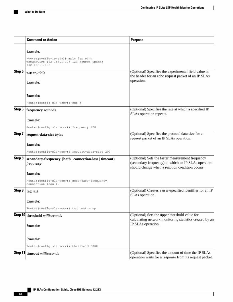
Command or Action Purpose
Example:
Router(config-ip-sla)# mpls lsp ping pseudowire 192.168.1.103 123 source-ipaddr 192.168.1.102
Step 5 exp exp-bits
Example:
Example:
Router(config-sla-vccv)# exp 5
(Optional) Specifies the experimental field value inthe header for an echo request packet of an IP SLAsoperation.
Step 6 frequency seconds
Example:
Router(config-sla-vccv)# frequency 120
(Optional) Specifies the rate at which a specified IPSLAs operation repeats.
Step 7 request-data-size bytes
Example:
Router(config-sla-vccv)# request-data-size 200
(Optional) Specifies the protocol data size for arequest packet of an IP SLAs operation.
Step 8 secondary-frequency {both | connection-loss | timeout}frequency
Example:
Router(config-sla-vccv)# secondary-frequency connection-loss 10
(Optional) Sets the faster measurement frequency(secondary frequency) to which an IP SLAs operationshould change when a reaction condition occurs.
Step 9 tag text
Example:
Router(config-sla-vccv)# tag testgroup
(Optional) Creates a user-specified identifier for an IPSLAs operation.
Step 10 threshold milliseconds
Example:
Example:
Router(config-sla-vccv)# threshold 6000
(Optional) Sets the upper threshold value forcalculating network monitoring statistics created by anIP SLAs operation.
Step 11 timeout milliseconds (Optional) Specifies the amount of time the IP SLAsoperation waits for a response from its request packet.
Configuring IP SLAs LSP Health Monitor Operations What to Do Next
IP SLAs Configuration Guide, Cisco IOS Release 12.2SX68
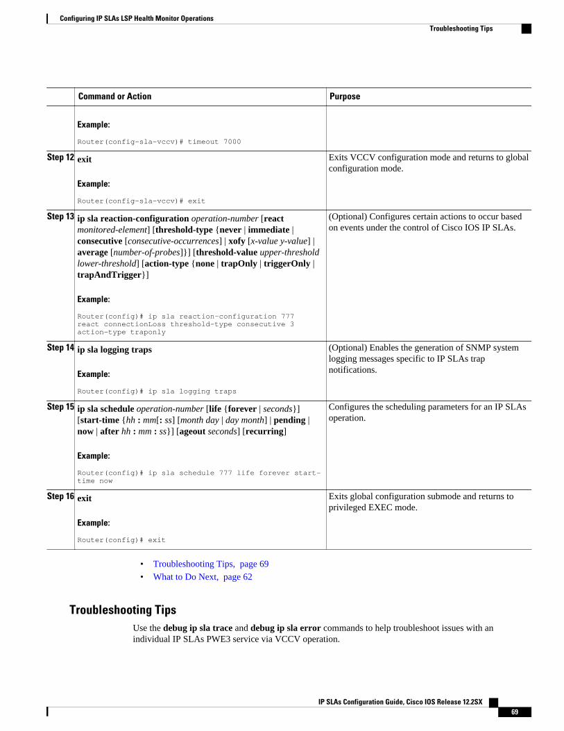
Command or Action Purpose
Example:
Router(config-sla-vccv)# timeout 7000
Step 12 exit
Example:
Router(config-sla-vccv)# exit
Exits VCCV configuration mode and returns to globalconfiguration mode.
Step 13 ip sla reaction-configuration operation-number [reactmonitored-element] [threshold-type {never | immediate |consecutive [consecutive-occurrences] | xofy [x-value y-value] |average [number-of-probes]}] [threshold-value upper-thresholdlower-threshold] [action-type {none | trapOnly | triggerOnly |trapAndTrigger}]
Example:
Router(config)# ip sla reaction-configuration 777 react connectionLoss threshold-type consecutive 3 action-type traponly
(Optional) Configures certain actions to occur basedon events under the control of Cisco IOS IP SLAs.
Step 14 ip sla logging traps
Example:
Router(config)# ip sla logging traps
(Optional) Enables the generation of SNMP systemlogging messages specific to IP SLAs trapnotifications.
Step 15 ip sla schedule operation-number [life {forever | seconds}][start-time {hh : mm[: ss] [month day | day month] | pending |now | after hh : mm : ss}] [ageout seconds] [recurring]
Example:
Router(config)# ip sla schedule 777 life forever start-time now
Configures the scheduling parameters for an IP SLAsoperation.
Step 16 exit
Example:
Router(config)# exit
Exits global configuration submode and returns toprivileged EXEC mode.
• Troubleshooting Tips, page 69
• What to Do Next, page 62
Troubleshooting TipsUse the debug ip sla trace and debug ip sla error commands to help troubleshoot issues with anindividual IP SLAs PWE3 service via VCCV operation.
Configuring IP SLAs LSP Health Monitor OperationsTroubleshooting Tips
IP SLAs Configuration Guide, Cisco IOS Release 12.2SX 69
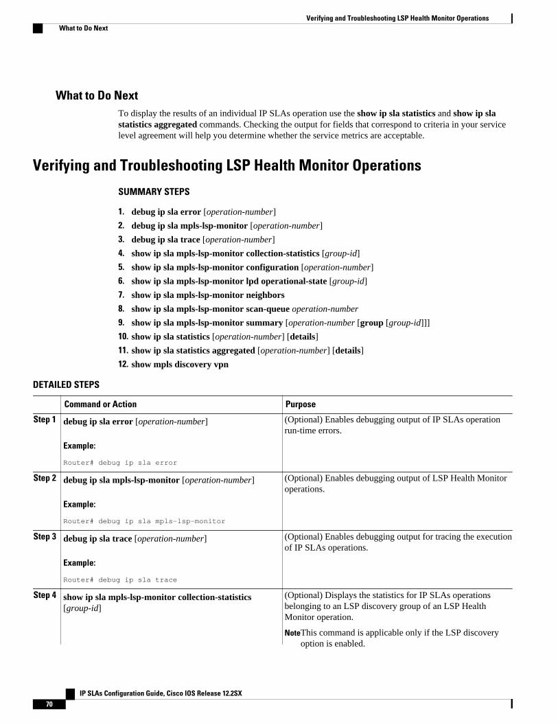
What to Do NextTo display the results of an individual IP SLAs operation use the show ip sla statistics and show ip slastatistics aggregated commands. Checking the output for fields that correspond to criteria in your servicelevel agreement will help you determine whether the service metrics are acceptable.
Verifying and Troubleshooting LSP Health Monitor Operations
SUMMARY STEPS
1. debug ip sla error [operation-number]
2. debug ip sla mpls-lsp-monitor [operation-number]
3. debug ip sla trace [operation-number]
4. show ip sla mpls-lsp-monitor collection-statistics [group-id]
5. show ip sla mpls-lsp-monitor configuration [operation-number]
6. show ip sla mpls-lsp-monitor lpd operational-state [group-id]
7. show ip sla mpls-lsp-monitor neighbors
8. show ip sla mpls-lsp-monitor scan-queue operation-number
9. show ip sla mpls-lsp-monitor summary [operation-number [group [group-id]]]
10. show ip sla statistics [operation-number] [details]
11. show ip sla statistics aggregated [operation-number] [details]
12. show mpls discovery vpn
DETAILED STEPS
Command or Action Purpose
Step 1 debug ip sla error [operation-number]
Example:
Router# debug ip sla error
(Optional) Enables debugging output of IP SLAs operationrun-time errors.
Step 2 debug ip sla mpls-lsp-monitor [operation-number]
Example:
Router# debug ip sla mpls-lsp-monitor
(Optional) Enables debugging output of LSP Health Monitoroperations.
Step 3 debug ip sla trace [operation-number]
Example:
Router# debug ip sla trace
(Optional) Enables debugging output for tracing the executionof IP SLAs operations.
Step 4 show ip sla mpls-lsp-monitor collection-statistics[group-id]
(Optional) Displays the statistics for IP SLAs operationsbelonging to an LSP discovery group of an LSP HealthMonitor operation.
NoteThis command is applicable only if the LSP discoveryoption is enabled.
Verifying and Troubleshooting LSP Health Monitor Operations What to Do Next
IP SLAs Configuration Guide, Cisco IOS Release 12.2SX70
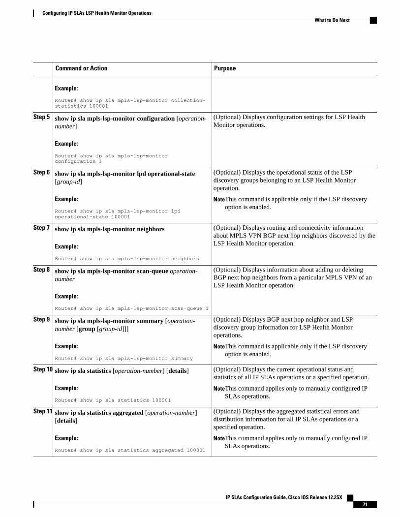
Command or Action Purpose
Example:
Router# show ip sla mpls-lsp-monitor collection-statistics 100001
Step 5 show ip sla mpls-lsp-monitor configuration [operation-number]
Example:
Router# show ip sla mpls-lsp-monitor configuration 1
(Optional) Displays configuration settings for LSP HealthMonitor operations.
Step 6 show ip sla mpls-lsp-monitor lpd operational-state[group-id]
Example:
Router# show ip sla mpls-lsp-monitor lpd operational-state 100001
(Optional) Displays the operational status of the LSPdiscovery groups belonging to an LSP Health Monitoroperation.
NoteThis command is applicable only if the LSP discoveryoption is enabled.
Step 7 show ip sla mpls-lsp-monitor neighbors
Example:
Router# show ip sla mpls-lsp-monitor neighbors
(Optional) Displays routing and connectivity informationabout MPLS VPN BGP next hop neighbors discovered by theLSP Health Monitor operation.
Step 8 show ip sla mpls-lsp-monitor scan-queue operation-number
Example:
Router# show ip sla mpls-lsp-monitor scan-queue 1
(Optional) Displays information about adding or deletingBGP next hop neighbors from a particular MPLS VPN of anLSP Health Monitor operation.
Step 9 show ip sla mpls-lsp-monitor summary [operation-number [group [group-id]]]
Example:
Router# show ip sla mpls-lsp-monitor summary
(Optional) Displays BGP next hop neighbor and LSPdiscovery group information for LSP Health Monitoroperations.
NoteThis command is applicable only if the LSP discoveryoption is enabled.
Step 10 show ip sla statistics [operation-number] [details]
Example:
Router# show ip sla statistics 100001
(Optional) Displays the current operational status andstatistics of all IP SLAs operations or a specified operation.
NoteThis command applies only to manually configured IPSLAs operations.
Step 11 show ip sla statistics aggregated [operation-number][details]
Example:
Router# show ip sla statistics aggregated 100001
(Optional) Displays the aggregated statistical errors anddistribution information for all IP SLAs operations or aspecified operation.
NoteThis command applies only to manually configured IPSLAs operations.
Configuring IP SLAs LSP Health Monitor OperationsWhat to Do Next
IP SLAs Configuration Guide, Cisco IOS Release 12.2SX 71
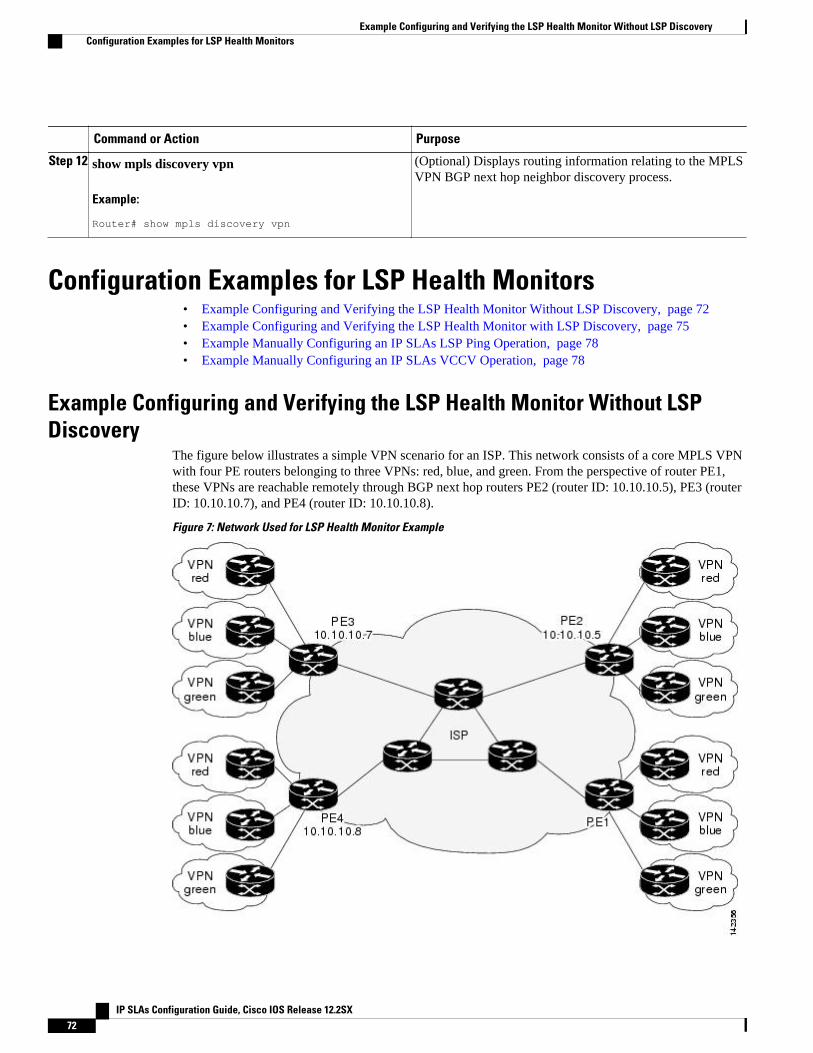
Command or Action Purpose
Step 12 show mpls discovery vpn
Example:
Router# show mpls discovery vpn
(Optional) Displays routing information relating to the MPLSVPN BGP next hop neighbor discovery process.
Configuration Examples for LSP Health Monitors• Example Configuring and Verifying the LSP Health Monitor Without LSP Discovery, page 72• Example Configuring and Verifying the LSP Health Monitor with LSP Discovery, page 75• Example Manually Configuring an IP SLAs LSP Ping Operation, page 78• Example Manually Configuring an IP SLAs VCCV Operation, page 78
Example Configuring and Verifying the LSP Health Monitor Without LSPDiscovery
The figure below illustrates a simple VPN scenario for an ISP. This network consists of a core MPLS VPNwith four PE routers belonging to three VPNs: red, blue, and green. From the perspective of router PE1,these VPNs are reachable remotely through BGP next hop routers PE2 (router ID: 10.10.10.5), PE3 (routerID: 10.10.10.7), and PE4 (router ID: 10.10.10.8).
Figure 7: Network Used for LSP Health Monitor Example
Example Configuring and Verifying the LSP Health Monitor Without LSP Discovery Configuration Examples for LSP Health Monitors
IP SLAs Configuration Guide, Cisco IOS Release 12.2SX72
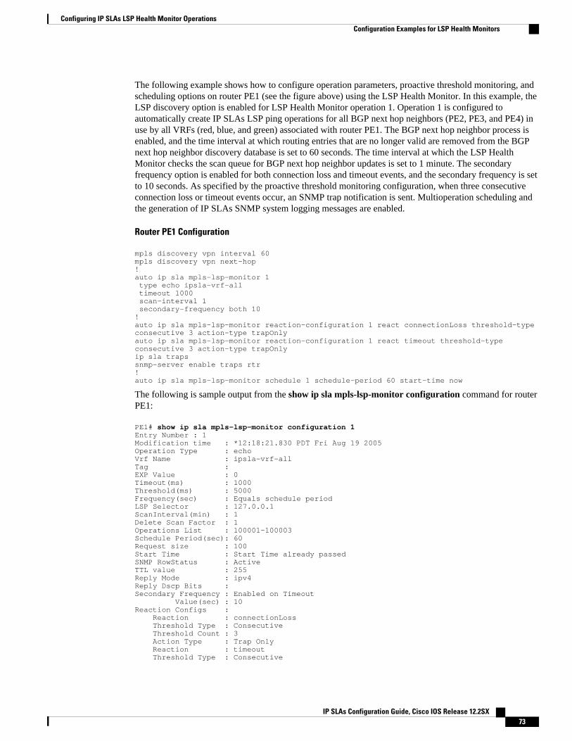
The following example shows how to configure operation parameters, proactive threshold monitoring, andscheduling options on router PE1 (see the figure above) using the LSP Health Monitor. In this example, theLSP discovery option is enabled for LSP Health Monitor operation 1. Operation 1 is configured toautomatically create IP SLAs LSP ping operations for all BGP next hop neighbors (PE2, PE3, and PE4) inuse by all VRFs (red, blue, and green) associated with router PE1. The BGP next hop neighbor process isenabled, and the time interval at which routing entries that are no longer valid are removed from the BGPnext hop neighbor discovery database is set to 60 seconds. The time interval at which the LSP HealthMonitor checks the scan queue for BGP next hop neighbor updates is set to 1 minute. The secondaryfrequency option is enabled for both connection loss and timeout events, and the secondary frequency is setto 10 seconds. As specified by the proactive threshold monitoring configuration, when three consecutiveconnection loss or timeout events occur, an SNMP trap notification is sent. Multioperation scheduling andthe generation of IP SLAs SNMP system logging messages are enabled.
Router PE1 Configuration
mpls discovery vpn interval 60mpls discovery vpn next-hop!auto ip sla mpls-lsp-monitor 1 type echo ipsla-vrf-all timeout 1000 scan-interval 1 secondary-frequency both 10!auto ip sla mpls-lsp-monitor reaction-configuration 1 react connectionLoss threshold-type consecutive 3 action-type trapOnlyauto ip sla mpls-lsp-monitor reaction-configuration 1 react timeout threshold-type consecutive 3 action-type trapOnlyip sla trapssnmp-server enable traps rtr!auto ip sla mpls-lsp-monitor schedule 1 schedule-period 60 start-time now
The following is sample output from the show ip sla mpls-lsp-monitor configuration command for routerPE1:
PE1# show ip sla mpls-lsp-monitor configuration 1Entry Number : 1Modification time : *12:18:21.830 PDT Fri Aug 19 2005Operation Type : echoVrf Name : ipsla-vrf-allTag : EXP Value : 0Timeout(ms) : 1000Threshold(ms) : 5000Frequency(sec) : Equals schedule periodLSP Selector : 127.0.0.1ScanInterval(min) : 1Delete Scan Factor : 1Operations List : 100001-100003Schedule Period(sec): 60Request size : 100Start Time : Start Time already passedSNMP RowStatus : ActiveTTL value : 255Reply Mode : ipv4Reply Dscp Bits : Secondary Frequency : Enabled on Timeout Value(sec) : 10Reaction Configs : Reaction : connectionLoss Threshold Type : Consecutive Threshold Count : 3 Action Type : Trap Only Reaction : timeout Threshold Type : Consecutive
Configuring IP SLAs LSP Health Monitor OperationsConfiguration Examples for LSP Health Monitors
IP SLAs Configuration Guide, Cisco IOS Release 12.2SX 73
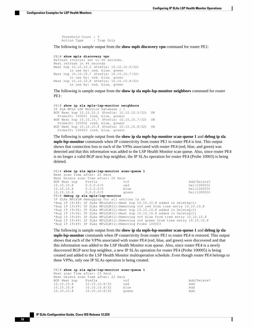
Threshold Count : 3 Action Type : Trap Only
The following is sample output from the show mpls discovery vpn command for router PE1:
PE1# show mpls discovery vpnRefresh interval set to 60 seconds.Next refresh in 46 secondsNext hop 10.10.10.5 (Prefix: 10.10.10.5/32) in use by: red, blue, greenNext hop 10.10.10.7 (Prefix: 10.10.10.7/32) in use by: red, blue, greenNext hop 10.10.10.8 (Prefix: 10.10.10.8/32) in use by: red, blue, green
The following is sample output from the show ip sla mpls-lsp-monitor neighbors command for routerPE1:
PE1# show ip sla mpls-lsp-monitor neighborsIP SLA MPLS LSP Monitor Database : 1BGP Next hop 10.10.10.5 (Prefix: 10.10.10.5/32) OK ProbeID: 100001 (red, blue, green)BGP Next hop 10.10.10.7 (Prefix: 10.10.10.7/32) OK ProbeID: 100002 (red, blue, green)BGP Next hop 10.10.10.8 (Prefix: 10.10.10.8/32) OK ProbeID: 100003 (red, blue, green)
The following is sample output from the show ip sla mpls-lsp-monitor scan-queue 1 and debug ip slampls-lsp-monitor commands when IP connectivity from router PE1 to router PE4 is lost. This outputshows that connection loss to each of the VPNs associated with router PE4 (red, blue, and green) wasdetected and that this information was added to the LSP Health Monitor scan queue. Also, since router PE4is no longer a valid BGP next hop neighbor, the IP SLAs operation for router PE4 (Probe 10003) is beingdeleted.
PE1# show ip sla mpls-lsp-monitor scan-queue 1Next scan Time after: 20 SecsNext Delete scan Time after: 20 SecsBGP Next hop Prefix vrf Add/Delete? 10.10.10.8 0.0.0.0/0 red Del(100003)10.10.10.8 0.0.0.0/0 blue Del(100003)10.10.10.8 0.0.0.0/0 green Del(100003)PE1# debug ip sla mpls-lsp-monitorIP SLAs MPLSLM debugging for all entries is on*Aug 19 19:48: IP SLAs MPLSLM(1):Next hop 10.10.10.8 added in DeleteQ(1)*Aug 19 19:49: IP SLAs MPLSLM(1):Removing vrf red from tree entry 10.10.10.8*Aug 19 19:56: IP SLAs MPLSLM(1):Next hop 10.10.10.8 added in DeleteQ(1)*Aug 19 19:56: IP SLAs MPLSLM(1):Next hop 10.10.10.8 added in DeleteQ(1)*Aug 19 19:49: IP SLAs MPLSLM(1):Removing vrf blue from tree entry 10.10.10.8*Aug 19 19:49: IP SLAs MPLSLM(1):Removing vrf green from tree entry 10.10.10.8*Aug 19 19:49: IP SLAs MPLSLM(1):Removing Probe 100003
The following is sample output from the show ip sla mpls-lsp-monitor scan-queue 1 and debug ip slampls-lsp-monitor commands when IP connectivity from router PE1 to router PE4 is restored. This outputshows that each of the VPNs associated with router PE4 (red, blue, and green) were discovered and thatthis information was added to the LSP Health Monitor scan queue. Also, since router PE4 is a newlydiscovered BGP next hop neighbor, a new IP SLAs operation for router PE4 (Probe 100005) is beingcreated and added to the LSP Health Monitor multioperation schedule. Even though router PE4 belongs tothree VPNs, only one IP SLAs operation is being created.
PE1# show ip sla mpls-lsp-monitor scan-queue 1Next scan Time after: 23 SecsNext Delete scan Time after: 23 SecsBGP Next hop Prefix vrf Add/Delete? 10.10.10.8 10.10.10.8/32 red Add10.10.10.8 10.10.10.8/32 blue Add10.10.10.8 10.10.10.8/32 green Add
Configuring IP SLAs LSP Health Monitor Operations Configuration Examples for LSP Health Monitors
IP SLAs Configuration Guide, Cisco IOS Release 12.2SX74
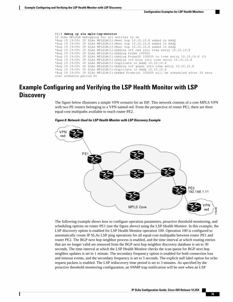
PE1# debug ip sla mpls-lsp-monitorIP SLAs MPLSLM debugging for all entries is on*Aug 19 19:59: IP SLAs MPLSLM(1):Next hop 10.10.10.8 added in AddQ*Aug 19 19:59: IP SLAs MPLSLM(1):Next hop 10.10.10.8 added in AddQ*Aug 19 19:59: IP SLAs MPLSLM(1):Next hop 10.10.10.8 added in AddQ*Aug 19 19:59: IP SLAs MPLSLM(1):Adding vrf red into tree entry 10.10.10.8*Aug 19 19:59: IP SLAs MPLSLM(1):Adding Probe 100005*Aug 19 19:59: IP SLAs MPLSLM(1):Adding ProbeID 100005 to tree entry 10.10.10.8 (1)*Aug 19 19:59: IP SLAs MPLSLM(1):Adding vrf blue into tree entry 10.10.10.8*Aug 19 19:59: IP SLAs MPLSLM(1):Duplicate in AddQ 10.10.10.8*Aug 19 19:59: IP SLAs MPLSLM(1):Adding vrf green into tree entry 10.10.10.8*Aug 19 19:59: IP SLAs MPLSLM(1):Duplicate in AddQ 10.10.10.8*Aug 19 19:59: IP SLAs MPLSLM(1):Added Probe(s) 100005 will be scheduled after 26 secs over schedule period 60
Example Configuring and Verifying the LSP Health Monitor with LSPDiscovery
The figure below illustrates a simple VPN scenario for an ISP. This network consists of a core MPLS VPNwith two PE routers belonging to a VPN named red. From the perspective of router PE1, there are threeequal-cost multipaths available to reach router PE2.
Figure 8: Network Used for LSP Health Monitor with LSP Discovery Example
The following example shows how to configure operation parameters, proactive threshold monitoring, andscheduling options on router PE1 (see the figure above) using the LSP Health Monitor. In this example, theLSP discovery option is enabled for LSP Health Monitor operation 100. Operation 100 is configured toautomatically create IP SLAs LSP ping operations for all equal-cost multipaths between router PE1 androuter PE2. The BGP next hop neighbor process is enabled, and the time interval at which routing entriesthat are no longer valid are removed from the BGP next hop neighbor discovery database is set to 30seconds. The time interval at which the LSP Health Monitor checks the scan queue for BGP next hopneighbor updates is set to 1 minute. The secondary frequency option is enabled for both connection lossand timeout events, and the secondary frequency is set to 5 seconds. The explicit null label option for echorequest packets is enabled. The LSP rediscovery time period is set to 3 minutes. As specified by theproactive threshold monitoring configuration, an SNMP trap notification will be sent when an LSP
Example Configuring and Verifying the LSP Health Monitor with LSP DiscoveryConfiguration Examples for LSP Health Monitors
IP SLAs Configuration Guide, Cisco IOS Release 12.2SX 75
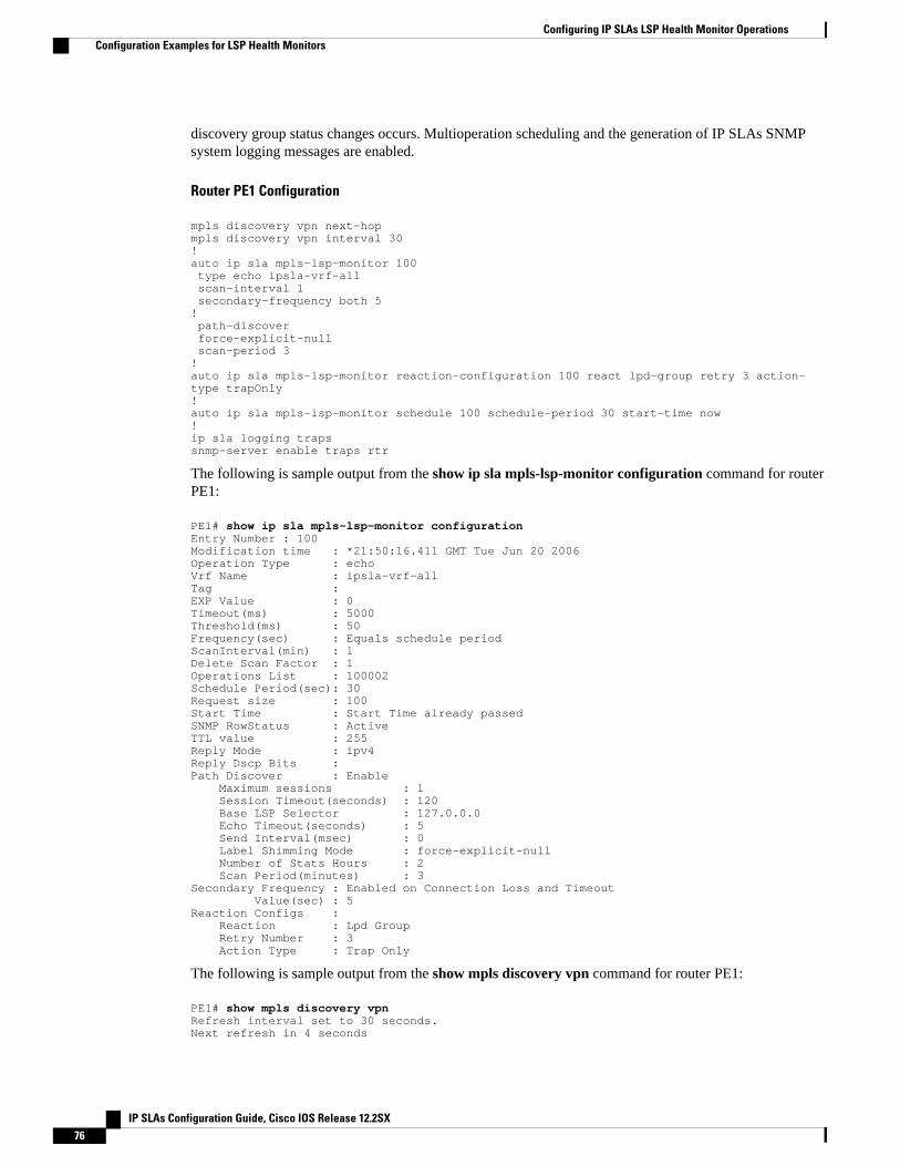
discovery group status changes occurs. Multioperation scheduling and the generation of IP SLAs SNMPsystem logging messages are enabled.
Router PE1 Configuration
mpls discovery vpn next-hopmpls discovery vpn interval 30!auto ip sla mpls-lsp-monitor 100 type echo ipsla-vrf-all scan-interval 1 secondary-frequency both 5! path-discover force-explicit-null scan-period 3!auto ip sla mpls-lsp-monitor reaction-configuration 100 react lpd-group retry 3 action-type trapOnly!auto ip sla mpls-lsp-monitor schedule 100 schedule-period 30 start-time now!ip sla logging trapssnmp-server enable traps rtr
The following is sample output from the show ip sla mpls-lsp-monitor configuration command for routerPE1:
PE1# show ip sla mpls-lsp-monitor configurationEntry Number : 100Modification time : *21:50:16.411 GMT Tue Jun 20 2006Operation Type : echoVrf Name : ipsla-vrf-allTag : EXP Value : 0Timeout(ms) : 5000Threshold(ms) : 50Frequency(sec) : Equals schedule periodScanInterval(min) : 1Delete Scan Factor : 1Operations List : 100002Schedule Period(sec): 30Request size : 100Start Time : Start Time already passedSNMP RowStatus : ActiveTTL value : 255Reply Mode : ipv4Reply Dscp Bits : Path Discover : Enable Maximum sessions : 1 Session Timeout(seconds) : 120 Base LSP Selector : 127.0.0.0 Echo Timeout(seconds) : 5 Send Interval(msec) : 0 Label Shimming Mode : force-explicit-null Number of Stats Hours : 2 Scan Period(minutes) : 3Secondary Frequency : Enabled on Connection Loss and Timeout Value(sec) : 5Reaction Configs : Reaction : Lpd Group Retry Number : 3 Action Type : Trap Only
The following is sample output from the show mpls discovery vpn command for router PE1:
PE1# show mpls discovery vpnRefresh interval set to 30 seconds.Next refresh in 4 seconds
Configuring IP SLAs LSP Health Monitor Operations Configuration Examples for LSP Health Monitors
IP SLAs Configuration Guide, Cisco IOS Release 12.2SX76
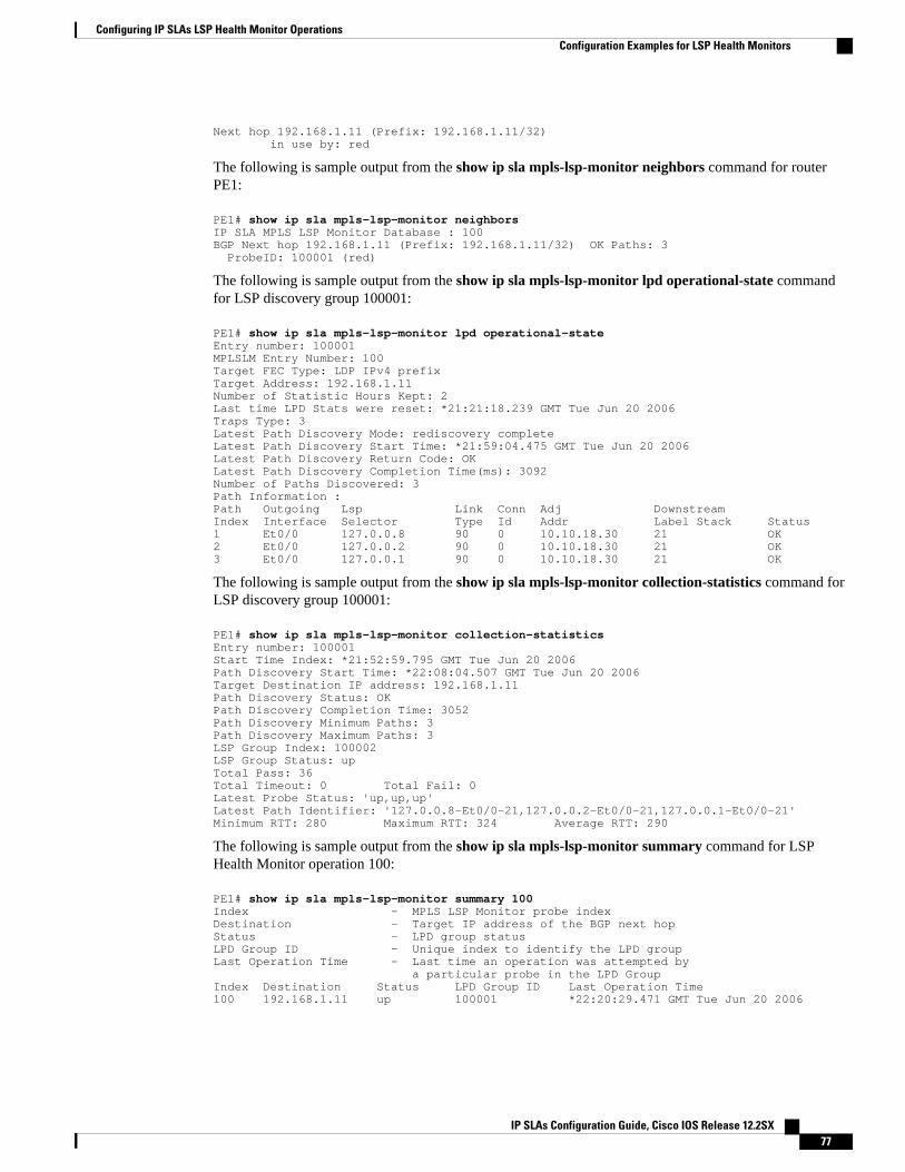
Next hop 192.168.1.11 (Prefix: 192.168.1.11/32) in use by: red
The following is sample output from the show ip sla mpls-lsp-monitor neighbors command for routerPE1:
PE1# show ip sla mpls-lsp-monitor neighborsIP SLA MPLS LSP Monitor Database : 100BGP Next hop 192.168.1.11 (Prefix: 192.168.1.11/32) OK Paths: 3 ProbeID: 100001 (red)
The following is sample output from the show ip sla mpls-lsp-monitor lpd operational-state commandfor LSP discovery group 100001:
PE1# show ip sla mpls-lsp-monitor lpd operational-stateEntry number: 100001MPLSLM Entry Number: 100Target FEC Type: LDP IPv4 prefixTarget Address: 192.168.1.11Number of Statistic Hours Kept: 2Last time LPD Stats were reset: *21:21:18.239 GMT Tue Jun 20 2006Traps Type: 3Latest Path Discovery Mode: rediscovery completeLatest Path Discovery Start Time: *21:59:04.475 GMT Tue Jun 20 2006Latest Path Discovery Return Code: OKLatest Path Discovery Completion Time(ms): 3092Number of Paths Discovered: 3Path Information :Path Outgoing Lsp Link Conn Adj Downstream Index Interface Selector Type Id Addr Label Stack Status 1 Et0/0 127.0.0.8 90 0 10.10.18.30 21 OK2 Et0/0 127.0.0.2 90 0 10.10.18.30 21 OK3 Et0/0 127.0.0.1 90 0 10.10.18.30 21 OK
The following is sample output from the show ip sla mpls-lsp-monitor collection-statistics command forLSP discovery group 100001:
PE1# show ip sla mpls-lsp-monitor collection-statisticsEntry number: 100001Start Time Index: *21:52:59.795 GMT Tue Jun 20 2006Path Discovery Start Time: *22:08:04.507 GMT Tue Jun 20 2006Target Destination IP address: 192.168.1.11Path Discovery Status: OKPath Discovery Completion Time: 3052Path Discovery Minimum Paths: 3Path Discovery Maximum Paths: 3LSP Group Index: 100002LSP Group Status: upTotal Pass: 36Total Timeout: 0 Total Fail: 0Latest Probe Status: 'up,up,up'Latest Path Identifier: '127.0.0.8-Et0/0-21,127.0.0.2-Et0/0-21,127.0.0.1-Et0/0-21'Minimum RTT: 280 Maximum RTT: 324 Average RTT: 290
The following is sample output from the show ip sla mpls-lsp-monitor summary command for LSPHealth Monitor operation 100:
PE1# show ip sla mpls-lsp-monitor summary 100Index - MPLS LSP Monitor probe indexDestination - Target IP address of the BGP next hopStatus - LPD group statusLPD Group ID - Unique index to identify the LPD groupLast Operation Time - Last time an operation was attempted by a particular probe in the LPD GroupIndex Destination Status LPD Group ID Last Operation Time100 192.168.1.11 up 100001 *22:20:29.471 GMT Tue Jun 20 2006
Configuring IP SLAs LSP Health Monitor OperationsConfiguration Examples for LSP Health Monitors
IP SLAs Configuration Guide, Cisco IOS Release 12.2SX 77
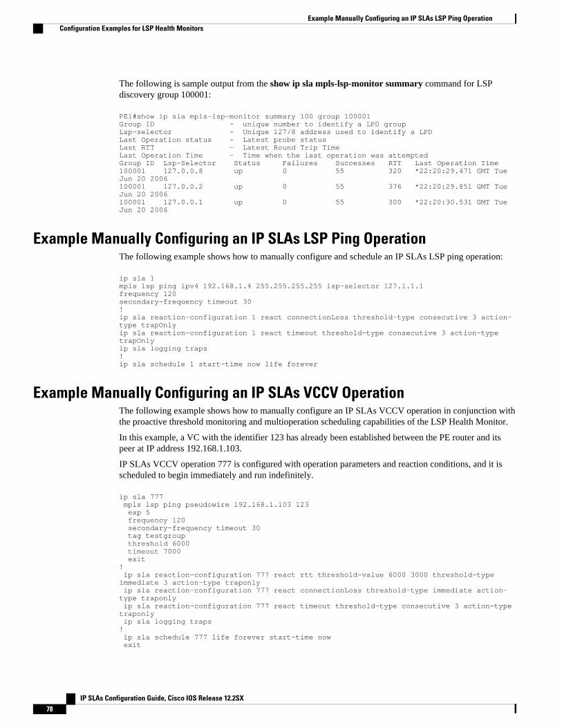
The following is sample output from the show ip sla mpls-lsp-monitor summary command for LSPdiscovery group 100001:
PE1#show ip sla mpls-lsp-monitor summary 100 group 100001Group ID - unique number to identify a LPD groupLsp-selector - Unique 127/8 address used to identify a LPDLast Operation status - Latest probe statusLast RTT - Latest Round Trip TimeLast Operation Time - Time when the last operation was attemptedGroup ID Lsp-Selector Status Failures Successes RTT Last Operation Time100001 127.0.0.8 up 0 55 320 *22:20:29.471 GMT Tue Jun 20 2006100001 127.0.0.2 up 0 55 376 *22:20:29.851 GMT Tue Jun 20 2006100001 127.0.0.1 up 0 55 300 *22:20:30.531 GMT Tue Jun 20 2006
Example Manually Configuring an IP SLAs LSP Ping OperationThe following example shows how to manually configure and schedule an IP SLAs LSP ping operation:
ip sla 1mpls lsp ping ipv4 192.168.1.4 255.255.255.255 lsp-selector 127.1.1.1frequency 120secondary-frequency timeout 30!ip sla reaction-configuration 1 react connectionLoss threshold-type consecutive 3 action-type trapOnlyip sla reaction-configuration 1 react timeout threshold-type consecutive 3 action-type trapOnlyip sla logging traps!ip sla schedule 1 start-time now life forever
Example Manually Configuring an IP SLAs VCCV OperationThe following example shows how to manually configure an IP SLAs VCCV operation in conjunction withthe proactive threshold monitoring and multioperation scheduling capabilities of the LSP Health Monitor.
In this example, a VC with the identifier 123 has already been established between the PE router and itspeer at IP address 192.168.1.103.
IP SLAs VCCV operation 777 is configured with operation parameters and reaction conditions, and it isscheduled to begin immediately and run indefinitely.
ip sla 777 mpls lsp ping pseudowire 192.168.1.103 123 exp 5 frequency 120 secondary-frequency timeout 30 tag testgroup threshold 6000 timeout 7000 exit! ip sla reaction-configuration 777 react rtt threshold-value 6000 3000 threshold-type immediate 3 action-type traponly ip sla reaction-configuration 777 react connectionLoss threshold-type immediate action-type traponly ip sla reaction-configuration 777 react timeout threshold-type consecutive 3 action-type traponly ip sla logging traps! ip sla schedule 777 life forever start-time now exit
Example Manually Configuring an IP SLAs LSP Ping Operation Configuration Examples for LSP Health Monitors
IP SLAs Configuration Guide, Cisco IOS Release 12.2SX78
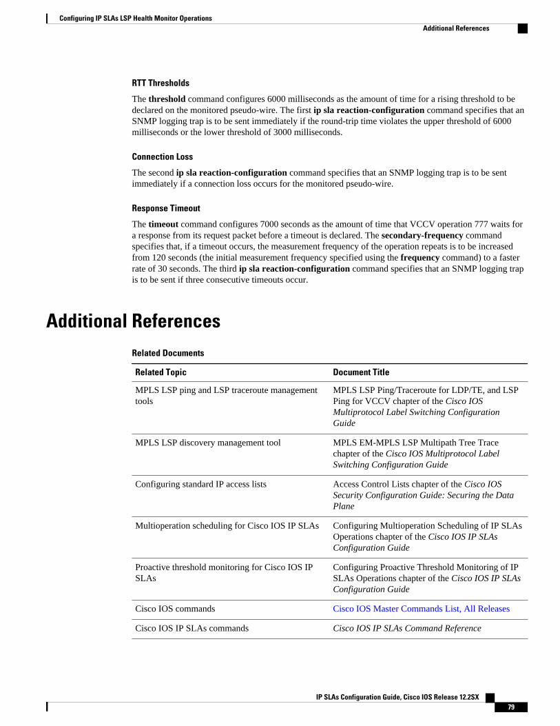
RTT Thresholds
The threshold command configures 6000 milliseconds as the amount of time for a rising threshold to bedeclared on the monitored pseudo-wire. The first ip sla reaction-configuration command specifies that anSNMP logging trap is to be sent immediately if the round-trip time violates the upper threshold of 6000milliseconds or the lower threshold of 3000 milliseconds.
Connection Loss
The second ip sla reaction-configuration command specifies that an SNMP logging trap is to be sentimmediately if a connection loss occurs for the monitored pseudo-wire.
Response Timeout
The timeout command configures 7000 seconds as the amount of time that VCCV operation 777 waits fora response from its request packet before a timeout is declared. The secondary-frequency commandspecifies that, if a timeout occurs, the measurement frequency of the operation repeats is to be increasedfrom 120 seconds (the initial measurement frequency specified using the frequency command) to a fasterrate of 30 seconds. The third ip sla reaction-configuration command specifies that an SNMP logging trapis to be sent if three consecutive timeouts occur.
Additional ReferencesRelated Documents
Related Topic Document Title
MPLS LSP ping and LSP traceroute managementtools
MPLS LSP Ping/Traceroute for LDP/TE, and LSPPing for VCCV chapter of the Cisco IOSMultiprotocol Label Switching ConfigurationGuide
MPLS LSP discovery management tool MPLS EM-MPLS LSP Multipath Tree Tracechapter of the Cisco IOS Multiprotocol LabelSwitching Configuration Guide
Configuring standard IP access lists Access Control Lists chapter of the Cisco IOSSecurity Configuration Guide: Securing the DataPlane
Multioperation scheduling for Cisco IOS IP SLAs Configuring Multioperation Scheduling of IP SLAsOperations chapter of the Cisco IOS IP SLAsConfiguration Guide
Proactive threshold monitoring for Cisco IOS IPSLAs
Configuring Proactive Threshold Monitoring of IPSLAs Operations chapter of the Cisco IOS IP SLAsConfiguration Guide
Cisco IOS commands Cisco IOS Master Commands List, All Releases
Cisco IOS IP SLAs commands Cisco IOS IP SLAs Command Reference
Configuring IP SLAs LSP Health Monitor OperationsAdditional References
IP SLAs Configuration Guide, Cisco IOS Release 12.2SX 79
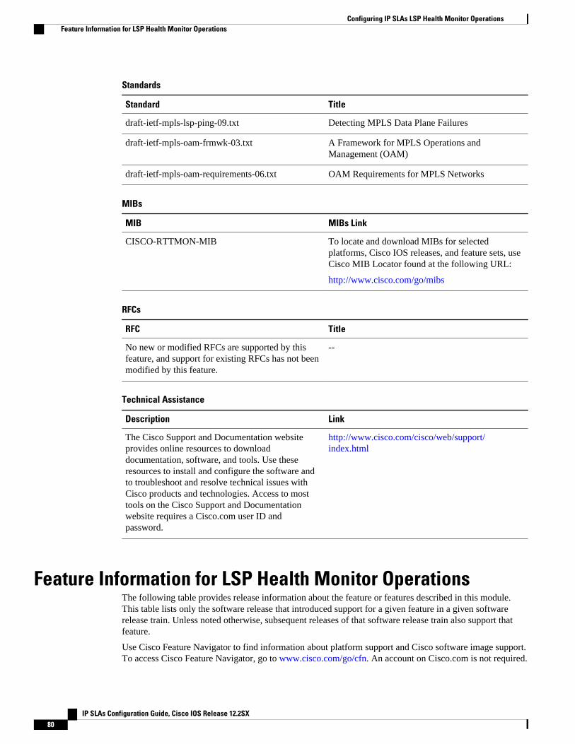
Standards
Standard Title
draft-ietf-mpls-lsp-ping-09.txt Detecting MPLS Data Plane Failures
draft-ietf-mpls-oam-frmwk-03.txt A Framework for MPLS Operations andManagement (OAM)
draft-ietf-mpls-oam-requirements-06.txt OAM Requirements for MPLS Networks
MIBs
MIB MIBs Link
CISCO-RTTMON-MIB To locate and download MIBs for selectedplatforms, Cisco IOS releases, and feature sets, useCisco MIB Locator found at the following URL:
http://www.cisco.com/go/mibs
RFCs
RFC Title
No new or modified RFCs are supported by thisfeature, and support for existing RFCs has not beenmodified by this feature.
--
Technical Assistance
Description Link
The Cisco Support and Documentation websiteprovides online resources to downloaddocumentation, software, and tools. Use theseresources to install and configure the software andto troubleshoot and resolve technical issues withCisco products and technologies. Access to mosttools on the Cisco Support and Documentationwebsite requires a Cisco.com user ID andpassword.
http://www.cisco.com/cisco/web/support/index.html
Feature Information for LSP Health Monitor OperationsThe following table provides release information about the feature or features described in this module.This table lists only the software release that introduced support for a given feature in a given softwarerelease train. Unless noted otherwise, subsequent releases of that software release train also support thatfeature.
Use Cisco Feature Navigator to find information about platform support and Cisco software image support.To access Cisco Feature Navigator, go to www.cisco.com/go/cfn. An account on Cisco.com is not required.
Configuring IP SLAs LSP Health Monitor Operations Feature Information for LSP Health Monitor Operations
IP SLAs Configuration Guide, Cisco IOS Release 12.2SX80
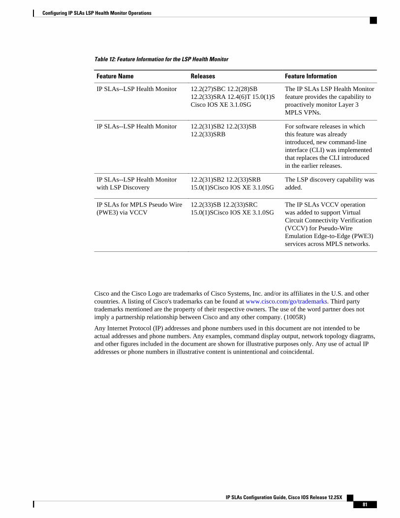
Table 12: Feature Information for the LSP Health Monitor
Feature Name Releases Feature Information
IP SLAs--LSP Health Monitor 12.2(27)SBC 12.2(28)SB12.2(33)SRA 12.4(6)T 15.0(1)SCisco IOS XE 3.1.0SG
The IP SLAs LSP Health Monitorfeature provides the capability toproactively monitor Layer 3MPLS VPNs.
IP SLAs--LSP Health Monitor 12.2(31)SB2 12.2(33)SB12.2(33)SRB
For software releases in whichthis feature was alreadyintroduced, new command-lineinterface (CLI) was implementedthat replaces the CLI introducedin the earlier releases.
IP SLAs--LSP Health Monitorwith LSP Discovery
12.2(31)SB2 12.2(33)SRB15.0(1)SCisco IOS XE 3.1.0SG
The LSP discovery capability wasadded.
IP SLAs for MPLS Pseudo Wire(PWE3) via VCCV
12.2(33)SB 12.2(33)SRC15.0(1)SCisco IOS XE 3.1.0SG
The IP SLAs VCCV operationwas added to support VirtualCircuit Connectivity Verification(VCCV) for Pseudo-WireEmulation Edge-to-Edge (PWE3)services across MPLS networks.
Cisco and the Cisco Logo are trademarks of Cisco Systems, Inc. and/or its affiliates in the U.S. and othercountries. A listing of Cisco's trademarks can be found at www.cisco.com/go/trademarks. Third partytrademarks mentioned are the property of their respective owners. The use of the word partner does notimply a partnership relationship between Cisco and any other company. (1005R)
Any Internet Protocol (IP) addresses and phone numbers used in this document are not intended to beactual addresses and phone numbers. Any examples, command display output, network topology diagrams,and other figures included in the document are shown for illustrative purposes only. Any use of actual IPaddresses or phone numbers in illustrative content is unintentional and coincidental.
Configuring IP SLAs LSP Health Monitor Operations
IP SLAs Configuration Guide, Cisco IOS Release 12.2SX 81

Example Manually Configuring an IP SLAs VCCV Operation
IP SLAs Configuration Guide, Cisco IOS Release 12.2SX82
Configuring IP SLAs for Metro-Ethernet
This module describes how to configure an IP Service Level Agreements (SLAs) for Metro-Ethernet togather network performance metrics in service-provider Ethernet networks. Available statisticalmeasurements for the IP SLAs Ethernet operation include round-trip time, jitter (interpacket delayvariance), and packet loss.
• Finding Feature Information, page 83• Prerequisites for IP SLAs for Metro-Ethernet, page 83• Restrictions for IP SLAs for Metro-Ethernet, page 83• Information About IP SLAs for Metro-Ethernet, page 84• How to Configure IP SLAs for Metro-Ethernet, page 84• Configuration Examples for IP SLAs for Metro-Ethernet, page 92• Additional References, page 94• Feature Information for IP SLAs for Metro-Ethernet, page 95
Finding Feature InformationYour software release may not support all the features documented in this module. For the latest featureinformation and caveats, see the release notes for your platform and software release. To find informationabout the features documented in this module, and to see a list of the releases in which each feature issupported, see the Feature Information Table at the end of this document.
Use Cisco Feature Navigator to find information about platform support and Cisco software image support.To access Cisco Feature Navigator, go to www.cisco.com/go/cfn. An account on Cisco.com is not required.
Prerequisites for IP SLAs for Metro-EthernetIt is recommended that the IEEE 802.1ag standard is supported on the destination devices in order to obtaincomplete error reporting and diagnostics information.
Restrictions for IP SLAs for Metro-EthernetMemory and performance may be impacted for a given Ethernet CFM maintenance domain and EthernetVirtual Circuit (EVC) or VLAN that has a large number of maintenance endpoints (MEPs).
IP SLAs Configuration Guide, Cisco IOS Release 12.2SX 83
Information About IP SLAs for Metro-Ethernet• IP SLAs Ethernet Operation Basics, page 84
IP SLAs Ethernet Operation BasicsThe IP SLAs for Metro-Ethernet integrates IP SLAs with the Ethernet Connectivity Fault Management(CFM) feature. Ethernet CFM is an end-to-end per-service-instance Ethernet-layer operation,administration, and management (OAM) protocol.
The IP SLAs for Metro-Ethernet feature provides the capability to gather statistical measurements bysending and receiving Ethernet data frames between Ethernet CFM maintenance endpoints (MEPs). Theperformance metrics for IP SLAs Ethernet operations are measured between a source MEP and adestination MEP. Unlike existing IP SLAs operations that provide performance metrics for the IP layer, theIP SLAs Ethernet operation provides performance metrics for Layer 2.
IP SLAs Ethernet operations may be configured using the command-line interface (CLI) or SimpleNetwork Management Protocol (SNMP).
You can manually configure individual Ethernet ping or Ethernet jitter operations by specifying thedestination MEP identification number, name of the maintenance domain, and EVC or VLAN identifier orport level option.
You also have the option to configure an IP SLAs auto Ethernet operation (ping or jitter) that will query theEthernet CFM database for all maintenance endpoints in a given maintenance domain and EVC or VLAN.When an IP SLAs auto Ethernet operation is configured, individual Ethernet ping or Ethernet jitteroperations are automatically created based on the MEPs that were discovered. A notification mechanismexists between the IP SLAs and Ethernet CFM subsystems to facilitate the automatic creation of Ethernetping or Ethernet jitter operations for applicable MEPs that are added to a given maintenance domain andEVC or VLAN while an auto Ethernet operation is running.
The IP SLAs for Metro-Ethernet feature supports multioperation scheduling of IP SLAs operations andproactive threshold violation monitoring through SNMP trap notifications and syslog messages.
Statistics Measured by the IP SLAs Ethernet Operation
The network performance metrics supported by the IP SLAs Ethernet operation is similar to the metricssupported by existing IP SLAs operations. The statistical measurements supported by the IP SLAs Ethernetjitter operation include the following:
• Jitter (source-to-destination and destination-to-source)• Round-trip time latency• Unprocessed packets• Packet loss (source-to-destination and destination-to-source)• Out-of-sequence, tail-dropped, and late packets
How to Configure IP SLAs for Metro-Ethernet
IP SLAs Ethernet Operation Basics Information About IP SLAs for Metro-Ethernet
IP SLAs Configuration Guide, Cisco IOS Release 12.2SX84
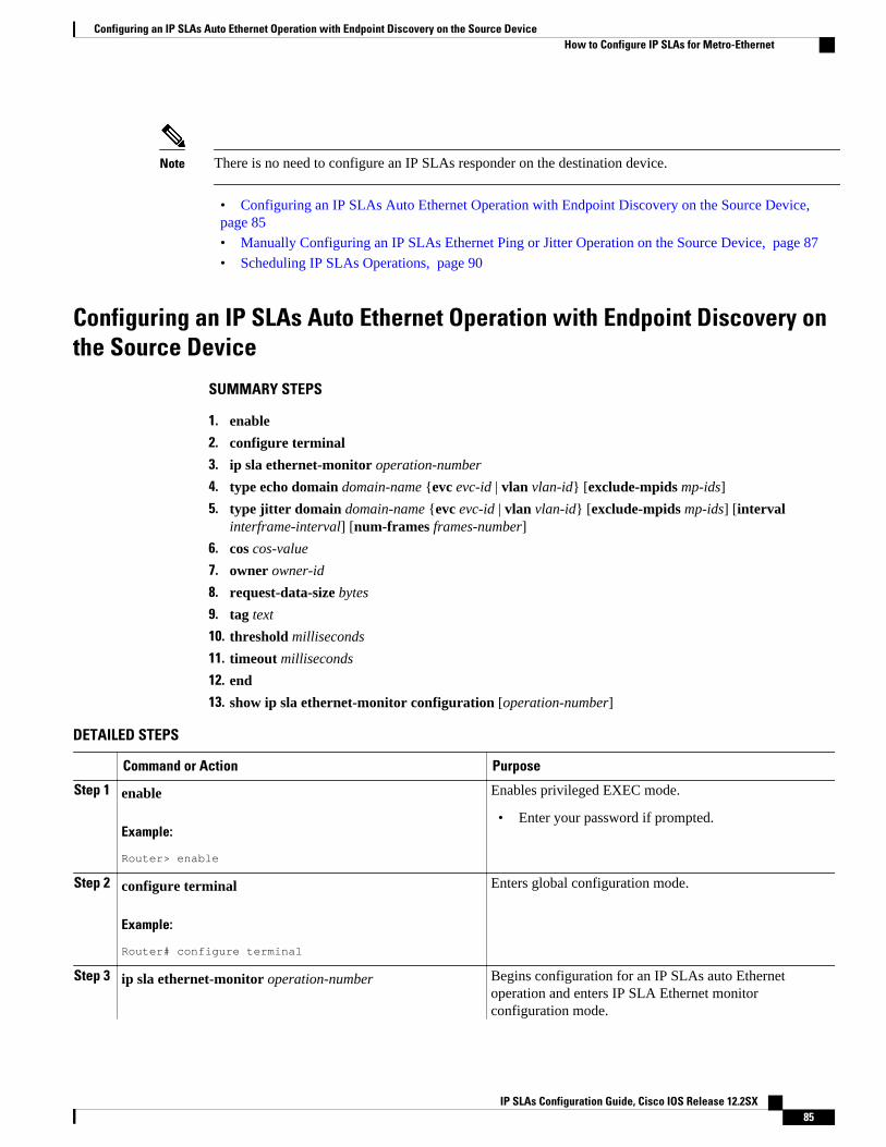
Note There is no need to configure an IP SLAs responder on the destination device.
• Configuring an IP SLAs Auto Ethernet Operation with Endpoint Discovery on the Source Device, page 85
• Manually Configuring an IP SLAs Ethernet Ping or Jitter Operation on the Source Device, page 87
• Scheduling IP SLAs Operations, page 90
Configuring an IP SLAs Auto Ethernet Operation with Endpoint Discovery onthe Source Device
SUMMARY STEPS
1. enable
2. configure terminal
3. ip sla ethernet-monitor operation-number
4. type echo domain domain-name {evc evc-id | vlan vlan-id} [exclude-mpids mp-ids]
5. type jitter domain domain-name {evc evc-id | vlan vlan-id} [exclude-mpids mp-ids] [intervalinterframe-interval] [num-frames frames-number]
6. cos cos-value
7. owner owner-id
8. request-data-size bytes
9. tag text
10. threshold milliseconds
11. timeout milliseconds
12. end
13. show ip sla ethernet-monitor configuration [operation-number]
DETAILED STEPS
Command or Action Purpose
Step 1 enable
Example:
Router> enable
Enables privileged EXEC mode.
• Enter your password if prompted.
Step 2 configure terminal
Example:
Router# configure terminal
Enters global configuration mode.
Step 3 ip sla ethernet-monitor operation-number Begins configuration for an IP SLAs auto Ethernetoperation and enters IP SLA Ethernet monitorconfiguration mode.
Configuring an IP SLAs Auto Ethernet Operation with Endpoint Discovery on the Source DeviceHow to Configure IP SLAs for Metro-Ethernet
IP SLAs Configuration Guide, Cisco IOS Release 12.2SX 85
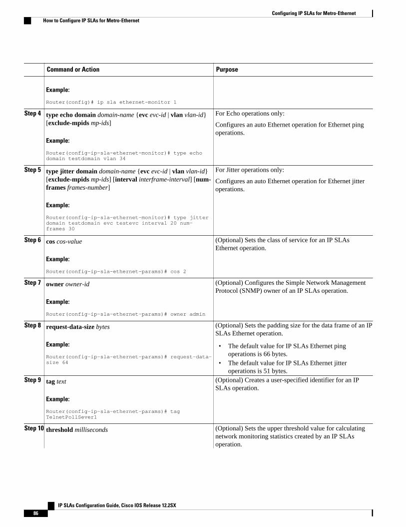
Command or Action Purpose
Example:
Router(config)# ip sla ethernet-monitor 1
Step 4 type echo domain domain-name {evc evc-id | vlan vlan-id}[exclude-mpids mp-ids]
Example:
Router(config-ip-sla-ethernet-monitor)# type echo domain testdomain vlan 34
For Echo operations only:
Configures an auto Ethernet operation for Ethernet pingoperations.
Step 5 type jitter domain domain-name {evc evc-id | vlan vlan-id}[exclude-mpids mp-ids] [interval interframe-interval] [num-frames frames-number]
Example:
Router(config-ip-sla-ethernet-monitor)# type jitter domain testdomain evc testevc interval 20 num-frames 30
For Jitter operations only:
Configures an auto Ethernet operation for Ethernet jitteroperations.
Step 6 cos cos-value
Example:
Router(config-ip-sla-ethernet-params)# cos 2
(Optional) Sets the class of service for an IP SLAsEthernet operation.
Step 7 owner owner-id
Example:
Router(config-ip-sla-ethernet-params)# owner admin
(Optional) Configures the Simple Network ManagementProtocol (SNMP) owner of an IP SLAs operation.
Step 8 request-data-size bytes
Example:
Router(config-ip-sla-ethernet-params)# request-data-size 64
(Optional) Sets the padding size for the data frame of an IPSLAs Ethernet operation.
• The default value for IP SLAs Ethernet pingoperations is 66 bytes.
• The default value for IP SLAs Ethernet jitteroperations is 51 bytes.
Step 9 tag text
Example:
Router(config-ip-sla-ethernet-params)# tag TelnetPollSever1
(Optional) Creates a user-specified identifier for an IPSLAs operation.
Step 10 threshold milliseconds (Optional) Sets the upper threshold value for calculatingnetwork monitoring statistics created by an IP SLAsoperation.
Configuring IP SLAs for Metro-Ethernet How to Configure IP SLAs for Metro-Ethernet
IP SLAs Configuration Guide, Cisco IOS Release 12.2SX86
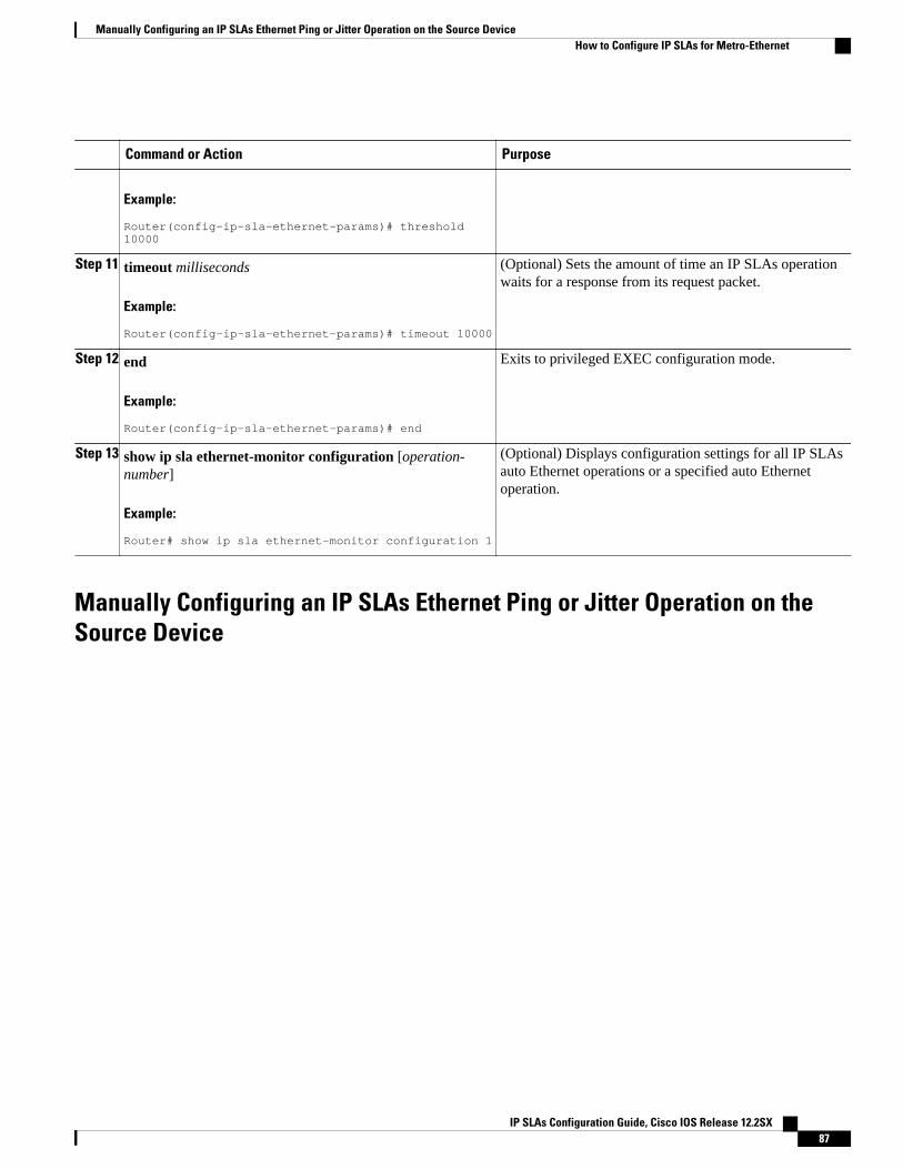
Command or Action Purpose
Example:
Router(config-ip-sla-ethernet-params)# threshold 10000
Step 11 timeout milliseconds
Example:
Router(config-ip-sla-ethernet-params)# timeout 10000
(Optional) Sets the amount of time an IP SLAs operationwaits for a response from its request packet.
Step 12 end
Example:
Router(config-ip-sla-ethernet-params)# end
Exits to privileged EXEC configuration mode.
Step 13 show ip sla ethernet-monitor configuration [operation-number]
Example:
Router# show ip sla ethernet-monitor configuration 1
(Optional) Displays configuration settings for all IP SLAsauto Ethernet operations or a specified auto Ethernetoperation.
Manually Configuring an IP SLAs Ethernet Ping or Jitter Operation on theSource Device
Manually Configuring an IP SLAs Ethernet Ping or Jitter Operation on the Source DeviceHow to Configure IP SLAs for Metro-Ethernet
IP SLAs Configuration Guide, Cisco IOS Release 12.2SX 87
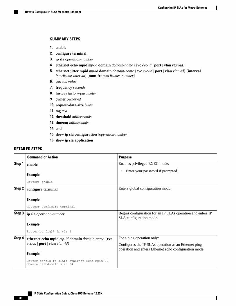
SUMMARY STEPS
1. enable
2. configure terminal
3. ip sla operation-number
4. ethernet echo mpid mp-id domain domain-name {evc evc-id | port | vlan vlan-id}
5. ethernet jitter mpid mp-id domain domain-name {evc evc-id | port | vlan vlan-id} [intervalinterframe-interval] [num-frames frames-number]
6. cos cos-value
7. frequency seconds
8. history history-parameter
9. owner owner-id
10. request-data-size bytes
11. tag text
12. threshold milliseconds
13. timeout milliseconds
14. end
15. show ip sla configuration [operation-number]
16. show ip sla application
DETAILED STEPS
Command or Action Purpose
Step 1 enable
Example:
Router> enable
Enables privileged EXEC mode.
• Enter your password if prompted.
Step 2 configure terminal
Example:
Router# configure terminal
Enters global configuration mode.
Step 3 ip sla operation-number
Example:
Router(config)# ip sla 1
Begins configuration for an IP SLAs operation and enters IPSLA configuration mode.
Step 4 ethernet echo mpid mp-id domain domain-name {evcevc-id | port | vlan vlan-id}
Example:
Router(config-ip-sla)# ethernet echo mpid 23 domain testdomain vlan 34
For a ping operation only:
Configures the IP SLAs operation as an Ethernet pingoperation and enters Ethernet echo configuration mode.
Configuring IP SLAs for Metro-Ethernet How to Configure IP SLAs for Metro-Ethernet
IP SLAs Configuration Guide, Cisco IOS Release 12.2SX88
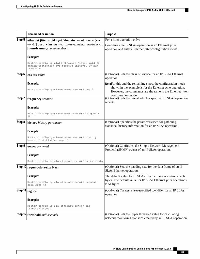
Command or Action Purpose
Step 5 ethernet jitter mpid mp-id domain domain-name {evcevc-id | port | vlan vlan-id} [interval interframe-interval][num-frames frames-number]
Example:
Router(config-ip-sla)# ethernet jitter mpid 23 domain testdomain evc testevc interval 20 num-frames 30
For a jitter operation only:
Configures the IP SLAs operation as an Ethernet jitteroperation and enters Ethernet jitter configuration mode.
Step 6 cos cos-value
Example:
Router(config-ip-sla-ethernet-echo)# cos 2
(Optional) Sets the class of service for an IP SLAs Ethernetoperation.
NoteFor this and the remaining steps, the configuration modeshown in the example is for the Ethernet echo operation.However, the commands are the same in the Ethernet jitterconfiguration mode.
Step 7 frequency seconds
Example:
Router(config-ip-sla-ethernet-echo)# frequency 30
(Optional) Sets the rate at which a specified IP SLAs operationrepeats.
Step 8 history history-parameter
Example:
Router(config-ip-sla-ethernet-echo)# history hours-of-statistics-kept 3
(Optional) Specifies the parameters used for gatheringstatistical history information for an IP SLAs operation.
Step 9 owner owner-id
Example:
Router(config-ip-sla-ethernet-echo)# owner admin
(Optional) Configures the Simple Network ManagementProtocol (SNMP) owner of an IP SLAs operation.
Step 10 request-data-size bytes
Example:
Router(config-ip-sla-ethernet-echo)# request-data-size 64
(Optional) Sets the padding size for the data frame of an IPSLAs Ethernet operation.
The default value for IP SLAs Ethernet ping operations is 66bytes. The default value for IP SLAs Ethernet jitter operationsis 51 bytes.
Step 11 tag text
Example:
Router(config-ip-sla-ethernet-echo)# tag TelnetPollSever1
(Optional) Creates a user-specified identifier for an IP SLAsoperation.
Step 12 threshold milliseconds (Optional) Sets the upper threshold value for calculatingnetwork monitoring statistics created by an IP SLAs operation.
Configuring IP SLAs for Metro-EthernetHow to Configure IP SLAs for Metro-Ethernet
IP SLAs Configuration Guide, Cisco IOS Release 12.2SX 89
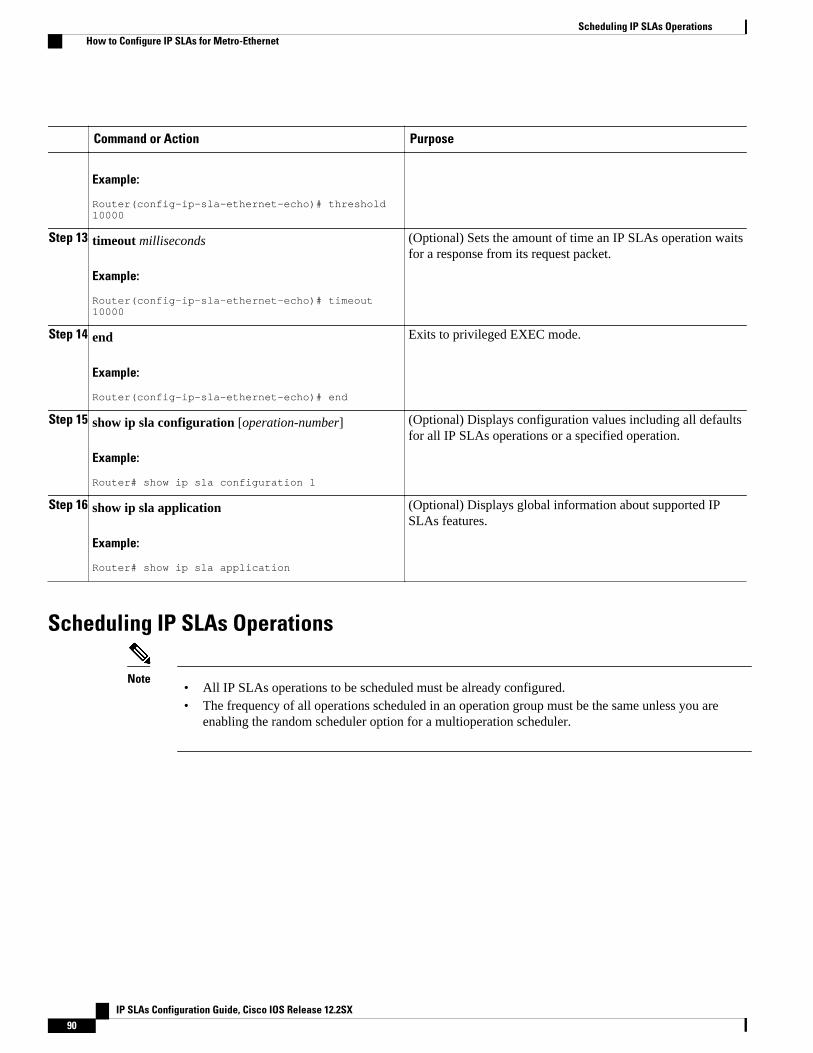
Command or Action Purpose
Example:
Router(config-ip-sla-ethernet-echo)# threshold 10000
Step 13 timeout milliseconds
Example:
Router(config-ip-sla-ethernet-echo)# timeout 10000
(Optional) Sets the amount of time an IP SLAs operation waitsfor a response from its request packet.
Step 14 end
Example:
Router(config-ip-sla-ethernet-echo)# end
Exits to privileged EXEC mode.
Step 15 show ip sla configuration [operation-number]
Example:
Router# show ip sla configuration 1
(Optional) Displays configuration values including all defaultsfor all IP SLAs operations or a specified operation.
Step 16 show ip sla application
Example:
Router# show ip sla application
(Optional) Displays global information about supported IPSLAs features.
Scheduling IP SLAs Operations
Note• All IP SLAs operations to be scheduled must be already configured.• The frequency of all operations scheduled in an operation group must be the same unless you are
enabling the random scheduler option for a multioperation scheduler.
Scheduling IP SLAs Operations How to Configure IP SLAs for Metro-Ethernet
IP SLAs Configuration Guide, Cisco IOS Release 12.2SX90
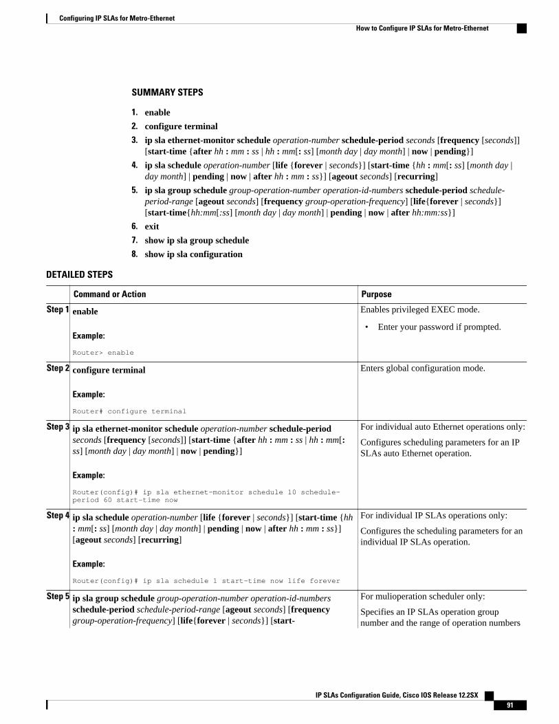
SUMMARY STEPS
1. enable
2. configure terminal
3. ip sla ethernet-monitor schedule operation-number schedule-period seconds [frequency [seconds]][start-time {after hh : mm : ss | hh : mm[: ss] [month day | day month] | now | pending}]
4. ip sla schedule operation-number [life {forever | seconds}] [start-time {hh : mm[: ss] [month day |day month] | pending | now | after hh : mm : ss}] [ageout seconds] [recurring]
5. ip sla group schedule group-operation-number operation-id-numbers schedule-period schedule-period-range [ageout seconds] [frequency group-operation-frequency] [life{forever | seconds}][start-time{hh:mm[:ss] [month day | day month] | pending | now | after hh:mm:ss}]
6. exit
7. show ip sla group schedule
8. show ip sla configuration
DETAILED STEPS
Command or Action Purpose
Step 1 enable
Example:
Router> enable
Enables privileged EXEC mode.
• Enter your password if prompted.
Step 2 configure terminal
Example:
Router# configure terminal
Enters global configuration mode.
Step 3 ip sla ethernet-monitor schedule operation-number schedule-periodseconds [frequency [seconds]] [start-time {after hh : mm : ss | hh : mm[:ss] [month day | day month] | now | pending}]
Example:
Router(config)# ip sla ethernet-monitor schedule 10 schedule-period 60 start-time now
For individual auto Ethernet operations only:
Configures scheduling parameters for an IPSLAs auto Ethernet operation.
Step 4 ip sla schedule operation-number [life {forever | seconds}] [start-time {hh: mm[: ss] [month day | day month] | pending | now | after hh : mm : ss}][ageout seconds] [recurring]
Example:
Router(config)# ip sla schedule 1 start-time now life forever
For individual IP SLAs operations only:
Configures the scheduling parameters for anindividual IP SLAs operation.
Step 5 ip sla group schedule group-operation-number operation-id-numbersschedule-period schedule-period-range [ageout seconds] [frequencygroup-operation-frequency] [life{forever | seconds}] [start-
For mulioperation scheduler only:
Specifies an IP SLAs operation groupnumber and the range of operation numbers
Configuring IP SLAs for Metro-EthernetHow to Configure IP SLAs for Metro-Ethernet
IP SLAs Configuration Guide, Cisco IOS Release 12.2SX 91
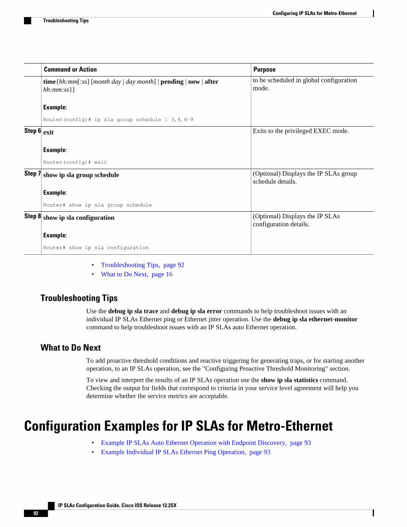
Command or Action Purpose
time{hh:mm[:ss] [month day | day month] | pending | now | afterhh:mm:ss}]
Example:
Router(config)# ip sla group schedule 1 3,4,6-9
to be scheduled in global configurationmode.
Step 6 exit
Example:
Router(config)# exit
Exits to the privileged EXEC mode.
Step 7 show ip sla group schedule
Example:
Router# show ip sla group schedule
(Optional) Displays the IP SLAs groupschedule details.
Step 8 show ip sla configuration
Example:
Router# show ip sla configuration
(Optional) Displays the IP SLAsconfiguration details.
• Troubleshooting Tips, page 92
• What to Do Next, page 16
Troubleshooting TipsUse the debug ip sla trace and debug ip sla error commands to help troubleshoot issues with anindividual IP SLAs Ethernet ping or Ethernet jitter operation. Use the debug ip sla ethernet-monitorcommand to help troubleshoot issues with an IP SLAs auto Ethernet operation.
What to Do NextTo add proactive threshold conditions and reactive triggering for generating traps, or for starting anotheroperation, to an IP SLAs operation, see the "Configuring Proactive Threshold Monitoring" section.
To view and interpret the results of an IP SLAs operation use the show ip sla statistics command.Checking the output for fields that correspond to criteria in your service level agreement will help youdetermine whether the service metrics are acceptable.
Configuration Examples for IP SLAs for Metro-Ethernet• Example IP SLAs Auto Ethernet Operation with Endpoint Discovery, page 93
• Example Individual IP SLAs Ethernet Ping Operation, page 93
Configuring IP SLAs for Metro-Ethernet Troubleshooting Tips
IP SLAs Configuration Guide, Cisco IOS Release 12.2SX92
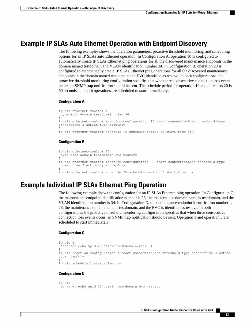
Example IP SLAs Auto Ethernet Operation with Endpoint DiscoveryThe following examples shows the operation parameters, proactive threshold monitoring, and schedulingoptions for an IP SLAs auto Ethernet operation. In Configuration A, operation 10 is configured toautomatically create IP SLAs Ethernet ping operations for all the discovered maintenance endpoints in thedomain named testdomain and VLAN identification number 34. In Configuration B, operation 20 isconfigured to automatically create IP SLAs Ethernet ping operations for all the discovered maintenanceendpoints in the domain named testdomain and EVC identified as testevc. In both configurations, theproactive threshold monitoring configuration specifies that when three consecutive connection loss eventsoccur, an SNMP trap notification should be sent. The schedule period for operation 10 and operation 20 is60 seconds, and both operations are scheduled to start immediately.
Configuration A
ip sla ethernet-monitor 10 type echo domain testdomain vlan 34!ip sla ethernet-monitor reaction-configuration 10 react connectionLoss threshold-type consecutive 3 action-type trapOnly!ip sla ethernet-monitor schedule 10 schedule-period 60 start-time now
Configuration B
ip sla ethernet-monitor 20 type echo domain testdomain evc testevc!ip sla ethernet-monitor reaction-configuration 20 react connectionLoss threshold-type consecutive 3 action-type trapOnly!ip sla ethernet-monitor schedule 20 schedule-period 60 start-time now
Example Individual IP SLAs Ethernet Ping OperationThe following example show the configuration for an IP SLAs Ethernet ping operation. In Configuration C,the maintenance endpoint identification number is 23, the maintenance domain name is testdomain, and theVLAN identification number is 34. In Configuration D, the maintenance endpoint identification number is23, the maintenance domain name is testdomain, and the EVC is identified as testevc. In bothconfigurations, the proactive threshold monitoring configuration specifies that when three consecutiveconnection loss events occur, an SNMP trap notification should be sent. Operation 1 and operation 5 arescheduled to start immediately.
Configuration C
ip sla 1 ethernet echo mpid 23 domain testdomain vlan 34!ip sla reaction-configuration 1 react connectionLoss threshold-type consecutive 3 action-type trapOnly!ip sla schedule 1 start-time now
Configuration D
ip sla 5 ethernet echo mpid 23 domain testdomain evc testevc
Example IP SLAs Auto Ethernet Operation with Endpoint DiscoveryConfiguration Examples for IP SLAs for Metro-Ethernet
IP SLAs Configuration Guide, Cisco IOS Release 12.2SX 93
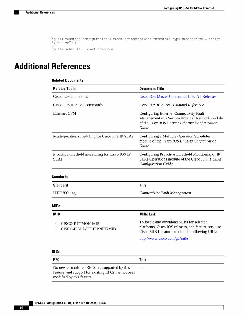
!ip sla reaction-configuration 5 react connectionLoss threshold-type consecutive 3 action-type trapOnly!ip sla schedule 5 start-time now
Additional ReferencesRelated Documents
Related Topic Document Title
Cisco IOS commands Cisco IOS Master Commands List, All Releases
Cisco IOS IP SLAs commands Cisco IOS IP SLAs Command Reference
Ethernet CFM Configuring Ethernet Connectivity FaultManagement in a Service Provider Network moduleof the Cisco IOS Carrier Ethernet ConfigurationGuide
Multioperation scheduling for Cisco IOS IP SLAs Configuring a Multiple Operation Schedulermodule of the Cisco IOS IP SLAs ConfigurationGuide
Proactive threshold monitoring for Cisco IOS IPSLAs
Configuring Proactive Threshold Monitoring of IPSLAs Operations module of the Cisco IOS IP SLAsConfiguration Guide
Standards
Standard Title
IEEE 802.1ag Connectivity Fault Management
MIBs
MIB MIBs Link
• CISCO-RTTMON-MIB• CISCO-IPSLA-ETHERNET-MIB
To locate and download MIBs for selectedplatforms, Cisco IOS releases, and feature sets, useCisco MIB Locator found at the following URL:
http://www.cisco.com/go/mibs
RFCs
RFC Title
No new or modified RFCs are supported by thisfeature, and support for existing RFCs has not beenmodified by this feature.
--
Configuring IP SLAs for Metro-Ethernet Additional References
IP SLAs Configuration Guide, Cisco IOS Release 12.2SX94
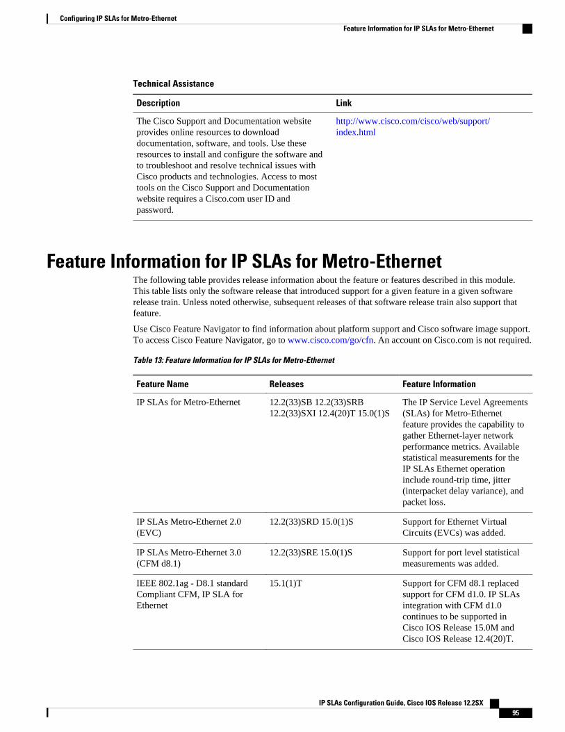
Technical Assistance
Description Link
The Cisco Support and Documentation websiteprovides online resources to downloaddocumentation, software, and tools. Use theseresources to install and configure the software andto troubleshoot and resolve technical issues withCisco products and technologies. Access to mosttools on the Cisco Support and Documentationwebsite requires a Cisco.com user ID andpassword.
http://www.cisco.com/cisco/web/support/index.html
Feature Information for IP SLAs for Metro-EthernetThe following table provides release information about the feature or features described in this module.This table lists only the software release that introduced support for a given feature in a given softwarerelease train. Unless noted otherwise, subsequent releases of that software release train also support thatfeature.
Use Cisco Feature Navigator to find information about platform support and Cisco software image support.To access Cisco Feature Navigator, go to www.cisco.com/go/cfn. An account on Cisco.com is not required.
Table 13: Feature Information for IP SLAs for Metro-Ethernet
Feature Name Releases Feature Information
IP SLAs for Metro-Ethernet 12.2(33)SB 12.2(33)SRB12.2(33)SXI 12.4(20)T 15.0(1)S
The IP Service Level Agreements(SLAs) for Metro-Ethernetfeature provides the capability togather Ethernet-layer networkperformance metrics. Availablestatistical measurements for theIP SLAs Ethernet operationinclude round-trip time, jitter(interpacket delay variance), andpacket loss.
IP SLAs Metro-Ethernet 2.0(EVC)
12.2(33)SRD 15.0(1)S Support for Ethernet VirtualCircuits (EVCs) was added.
IP SLAs Metro-Ethernet 3.0(CFM d8.1)
12.2(33)SRE 15.0(1)S Support for port level statisticalmeasurements was added.
IEEE 802.1ag - D8.1 standardCompliant CFM, IP SLA forEthernet
15.1(1)T Support for CFM d8.1 replacedsupport for CFM d1.0. IP SLAsintegration with CFM d1.0continues to be supported inCisco IOS Release 15.0M andCisco IOS Release 12.4(20)T.
Configuring IP SLAs for Metro-EthernetFeature Information for IP SLAs for Metro-Ethernet
IP SLAs Configuration Guide, Cisco IOS Release 12.2SX 95
Cisco and the Cisco Logo are trademarks of Cisco Systems, Inc. and/or its affiliates in the U.S. and othercountries. A listing of Cisco's trademarks can be found at www.cisco.com/go/trademarks. Third partytrademarks mentioned are the property of their respective owners. The use of the word partner does notimply a partnership relationship between Cisco and any other company. (1005R)
Any Internet Protocol (IP) addresses and phone numbers used in this document are not intended to beactual addresses and phone numbers. Any examples, command display output, network topology diagrams,and other figures included in the document are shown for illustrative purposes only. Any use of actual IPaddresses or phone numbers in illustrative content is unintentional and coincidental.
Configuring IP SLAs for Metro-Ethernet
IP SLAs Configuration Guide, Cisco IOS Release 12.2SX96
Configuring IP SLAs UDP Echo Operations
This module describes how to configure an IP Service Level Agreements (SLAs) User Datagram Protocol(UDP) Echo operation to monitor end-to-end response time between a Cisco router and devices usingIPv4 or IPv6. UDP echo accuracy is enhanced by using the IP SLAs Responder at the destination Ciscorouter. This module also demonstrates how the results of the UDP echo operation can be displayed andanalyzed to determine how a UDP application is performing.
• Finding Feature Information, page 97• Restrictions for IP SLAs UDP Echo Operations, page 97• Information About IP SLAs UDP Echo Operations, page 97• How to Configure IP SLAs UDP Echo Operations, page 98• Configuration Examples for IP SLAs UDP Echo Operations, page 106• Additional References, page 107• Feature Information for the IP SLAs UDP Echo Operation, page 108
Finding Feature InformationYour software release may not support all the features documented in this module. For the latest featureinformation and caveats, see the release notes for your platform and software release. To find informationabout the features documented in this module, and to see a list of the releases in which each feature issupported, see the Feature Information Table at the end of this document.
Use Cisco Feature Navigator to find information about platform support and Cisco software image support.To access Cisco Feature Navigator, go to www.cisco.com/go/cfn. An account on Cisco.com is not required.
Restrictions for IP SLAs UDP Echo OperationsWe recommend using a Cisco networking device as the destination device, although any networking devicethat supports RFC 862, Echo Protocol , can be used.
Information About IP SLAs UDP Echo Operations• UDP Echo Operation, page 98
IP SLAs Configuration Guide, Cisco IOS Release 12.2SX 97
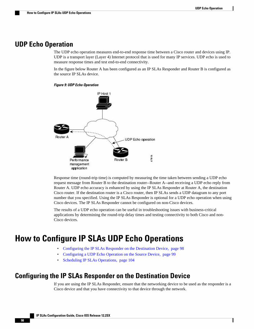
UDP Echo OperationThe UDP echo operation measures end-to-end response time between a Cisco router and devices using IP.UDP is a transport layer (Layer 4) Internet protocol that is used for many IP services. UDP echo is used tomeasure response times and test end-to-end connectivity.
In the figure below Router A has been configured as an IP SLAs Responder and Router B is configured asthe source IP SLAs device.
Figure 9: UDP Echo Operation
Response time (round-trip time) is computed by measuring the time taken between sending a UDP echorequest message from Router B to the destination router--Router A--and receiving a UDP echo reply fromRouter A. UDP echo accuracy is enhanced by using the IP SLAs Responder at Router A, the destinationCisco router. If the destination router is a Cisco router, then IP SLAs sends a UDP datagram to any portnumber that you specified. Using the IP SLAs Responder is optional for a UDP echo operation when usingCisco devices. The IP SLAs Responder cannot be configured on non-Cisco devices.
The results of a UDP echo operation can be useful in troubleshooting issues with business-criticalapplications by determining the round-trip delay times and testing connectivity to both Cisco and non-Cisco devices.
How to Configure IP SLAs UDP Echo Operations• Configuring the IP SLAs Responder on the Destination Device, page 98
• Configuring a UDP Echo Operation on the Source Device, page 99
• Scheduling IP SLAs Operations, page 104
Configuring the IP SLAs Responder on the Destination DeviceIf you are using the IP SLAs Responder, ensure that the networking device to be used as the responder is aCisco device and that you have connectivity to that device through the network.
UDP Echo Operation How to Configure IP SLAs UDP Echo Operations
IP SLAs Configuration Guide, Cisco IOS Release 12.2SX98
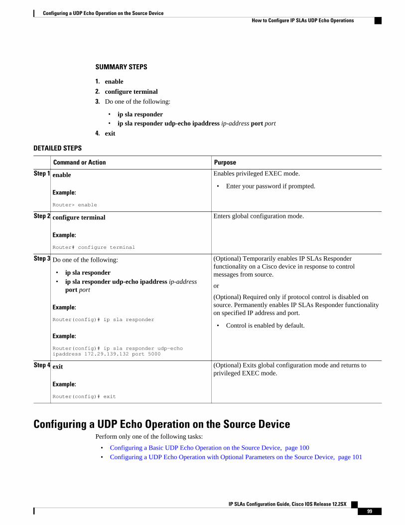
SUMMARY STEPS
1. enable
2. configure terminal
3. Do one of the following:
• ip sla responder• ip sla responder udp-echo ipaddress ip-address port port
4. exit
DETAILED STEPS
Command or Action Purpose
Step 1 enable
Example:
Router> enable
Enables privileged EXEC mode.
• Enter your password if prompted.
Step 2 configure terminal
Example:
Router# configure terminal
Enters global configuration mode.
Step 3 Do one of the following:
• ip sla responder• ip sla responder udp-echo ipaddress ip-address
port port
Example:
Router(config)# ip sla responder
Example:
Router(config)# ip sla responder udp-echo ipaddress 172.29.139.132 port 5000
(Optional) Temporarily enables IP SLAs Responderfunctionality on a Cisco device in response to controlmessages from source.
or
(Optional) Required only if protocol control is disabled onsource. Permanently enables IP SLAs Responder functionalityon specified IP address and port.
• Control is enabled by default.
Step 4 exit
Example:
Router(config)# exit
(Optional) Exits global configuration mode and returns toprivileged EXEC mode.
Configuring a UDP Echo Operation on the Source DevicePerform only one of the following tasks:
• Configuring a Basic UDP Echo Operation on the Source Device, page 100
• Configuring a UDP Echo Operation with Optional Parameters on the Source Device, page 101
Configuring a UDP Echo Operation on the Source DeviceHow to Configure IP SLAs UDP Echo Operations
IP SLAs Configuration Guide, Cisco IOS Release 12.2SX 99
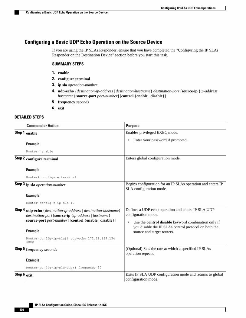
Configuring a Basic UDP Echo Operation on the Source DeviceIf you are using the IP SLAs Responder, ensure that you have completed the "Configuring the IP SLAsResponder on the Destination Device" section before you start this task.
SUMMARY STEPS
1. enable
2. configure terminal
3. ip sla operation-number
4. udp-echo {destination-ip-address | destination-hostname} destination-port [source-ip {ip-address |hostname} source-port port-number] [control {enable | disable}]
5. frequency seconds
6. exit
DETAILED STEPS
Command or Action Purpose
Step 1 enable
Example:
Router> enable
Enables privileged EXEC mode.
• Enter your password if prompted.
Step 2 configure terminal
Example:
Router# configure terminal
Enters global configuration mode.
Step 3 ip sla operation-number
Example:
Router(config)# ip sla 10
Begins configuration for an IP SLAs operation and enters IPSLA configuration mode.
Step 4 udp-echo {destination-ip-address | destination-hostname}destination-port [source-ip {ip-address | hostname}source-port port-number] [control {enable | disable}]
Example:
Router(config-ip-sla)# udp-echo 172.29.139.134 5000
Defines a UDP echo operation and enters IP SLA UDPconfiguration mode.
• Use the control disable keyword combination only ifyou disable the IP SLAs control protocol on both thesource and target routers.
Step 5 frequency seconds
Example:
Router(config-ip-sla-udp)# frequency 30
(Optional) Sets the rate at which a specified IP SLAsoperation repeats.
Step 6 exit Exits IP SLA UDP configuration mode and returns to globalconfiguration mode.
Configuring IP SLAs UDP Echo Operations Configuring a Basic UDP Echo Operation on the Source Device
IP SLAs Configuration Guide, Cisco IOS Release 12.2SX100
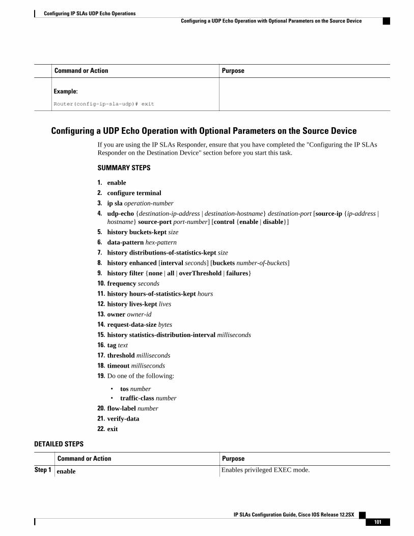
Command or Action Purpose
Example:
Router(config-ip-sla-udp)# exit
Configuring a UDP Echo Operation with Optional Parameters on the Source DeviceIf you are using the IP SLAs Responder, ensure that you have completed the "Configuring the IP SLAsResponder on the Destination Device" section before you start this task.
SUMMARY STEPS
1. enable
2. configure terminal
3. ip sla operation-number
4. udp-echo {destination-ip-address | destination-hostname} destination-port [source-ip {ip-address |hostname} source-port port-number] [control {enable | disable}]
5. history buckets-kept size
6. data-pattern hex-pattern
7. history distributions-of-statistics-kept size
8. history enhanced [interval seconds] [buckets number-of-buckets]
9. history filter {none | all | overThreshold | failures}
10. frequency seconds
11. history hours-of-statistics-kept hours
12. history lives-kept lives
13. owner owner-id
14. request-data-size bytes
15. history statistics-distribution-interval milliseconds
16. tag text
17. threshold milliseconds
18. timeout milliseconds
19. Do one of the following:
• tos number• traffic-class number
20. flow-label number
21. verify-data
22. exit
DETAILED STEPS
Command or Action Purpose
Step 1 enable Enables privileged EXEC mode.
Configuring IP SLAs UDP Echo OperationsConfiguring a UDP Echo Operation with Optional Parameters on the Source Device
IP SLAs Configuration Guide, Cisco IOS Release 12.2SX 101
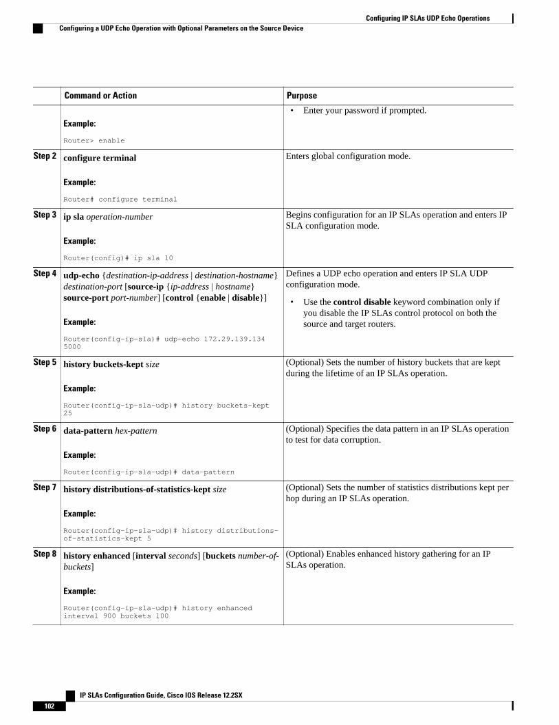
Command or Action Purpose
Example:
Router> enable
• Enter your password if prompted.
Step 2 configure terminal
Example:
Router# configure terminal
Enters global configuration mode.
Step 3 ip sla operation-number
Example:
Router(config)# ip sla 10
Begins configuration for an IP SLAs operation and enters IPSLA configuration mode.
Step 4 udp-echo {destination-ip-address | destination-hostname}destination-port [source-ip {ip-address | hostname}source-port port-number] [control {enable | disable}]
Example:
Router(config-ip-sla)# udp-echo 172.29.139.134 5000
Defines a UDP echo operation and enters IP SLA UDPconfiguration mode.
• Use the control disable keyword combination only ifyou disable the IP SLAs control protocol on both thesource and target routers.
Step 5 history buckets-kept size
Example:
Router(config-ip-sla-udp)# history buckets-kept 25
(Optional) Sets the number of history buckets that are keptduring the lifetime of an IP SLAs operation.
Step 6 data-pattern hex-pattern
Example:
Router(config-ip-sla-udp)# data-pattern
(Optional) Specifies the data pattern in an IP SLAs operationto test for data corruption.
Step 7 history distributions-of-statistics-kept size
Example:
Router(config-ip-sla-udp)# history distributions-of-statistics-kept 5
(Optional) Sets the number of statistics distributions kept perhop during an IP SLAs operation.
Step 8 history enhanced [interval seconds] [buckets number-of-buckets]
Example:
Router(config-ip-sla-udp)# history enhanced interval 900 buckets 100
(Optional) Enables enhanced history gathering for an IPSLAs operation.
Configuring IP SLAs UDP Echo Operations Configuring a UDP Echo Operation with Optional Parameters on the Source Device
IP SLAs Configuration Guide, Cisco IOS Release 12.2SX102
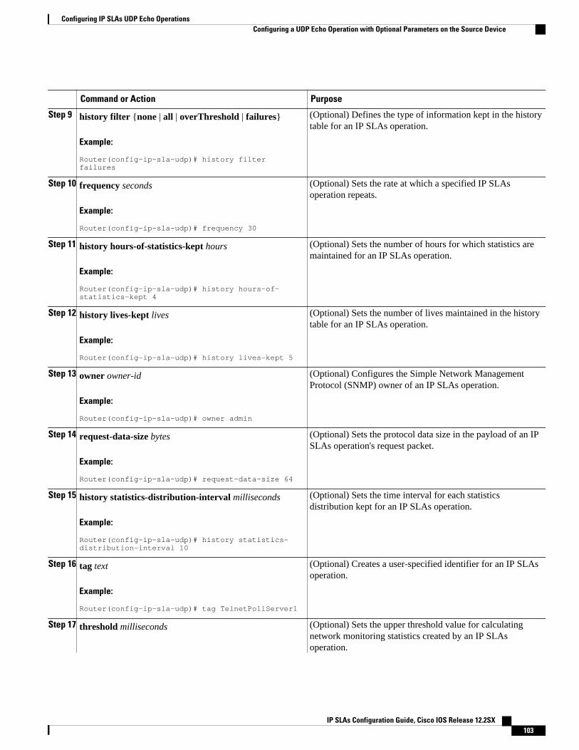
Command or Action Purpose
Step 9 history filter {none | all | overThreshold | failures}
Example:
Router(config-ip-sla-udp)# history filter failures
(Optional) Defines the type of information kept in the historytable for an IP SLAs operation.
Step 10 frequency seconds
Example:
Router(config-ip-sla-udp)# frequency 30
(Optional) Sets the rate at which a specified IP SLAsoperation repeats.
Step 11 history hours-of-statistics-kept hours
Example:
Router(config-ip-sla-udp)# history hours-of-statistics-kept 4
(Optional) Sets the number of hours for which statistics aremaintained for an IP SLAs operation.
Step 12 history lives-kept lives
Example:
Router(config-ip-sla-udp)# history lives-kept 5
(Optional) Sets the number of lives maintained in the historytable for an IP SLAs operation.
Step 13 owner owner-id
Example:
Router(config-ip-sla-udp)# owner admin
(Optional) Configures the Simple Network ManagementProtocol (SNMP) owner of an IP SLAs operation.
Step 14 request-data-size bytes
Example:
Router(config-ip-sla-udp)# request-data-size 64
(Optional) Sets the protocol data size in the payload of an IPSLAs operation's request packet.
Step 15 history statistics-distribution-interval milliseconds
Example:
Router(config-ip-sla-udp)# history statistics-distribution-interval 10
(Optional) Sets the time interval for each statisticsdistribution kept for an IP SLAs operation.
Step 16 tag text
Example:
Router(config-ip-sla-udp)# tag TelnetPollServer1
(Optional) Creates a user-specified identifier for an IP SLAsoperation.
Step 17 threshold milliseconds (Optional) Sets the upper threshold value for calculatingnetwork monitoring statistics created by an IP SLAsoperation.
Configuring IP SLAs UDP Echo OperationsConfiguring a UDP Echo Operation with Optional Parameters on the Source Device
IP SLAs Configuration Guide, Cisco IOS Release 12.2SX 103
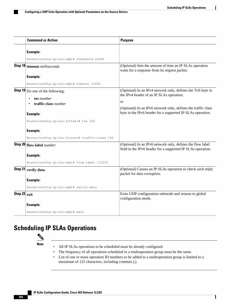
Command or Action Purpose
Example:
Router(config-ip-sla-udp)# threshold 10000
Step 18 timeout milliseconds
Example:
Router(config-ip-sla-udp)# timeout 10000
(Optional) Sets the amount of time an IP SLAs operationwaits for a response from its request packet.
Step 19 Do one of the following:
• tos number• traffic-class number
Example:
Router(config-ip-sla-jitter)# tos 160
Example:
Router(config-ip-sla-jitter)# traffic-class 160
(Optional) In an IPv4 network only, defines the ToS byte inthe IPv4 header of an IP SLAs operation.
or
(Optional) In an IPv6 network only, defines the traffic classbyte in the IPv6 header for a supported IP SLAs operation.
Step 20 flow-label number
Example:
Router(config-ip-sla-udp)# flow-label 112233
(Optional) In an IPv6 network only, defines the flow labelfield in the IPv6 header for a supported IP SLAs operation.
Step 21 verify-data
Example:
Router(config-ip-sla-udp)# verify-data
(Optional) Causes an IP SLAs operation to check each replypacket for data corruption.
Step 22 exit
Example:
Router(config-ip-sla-udp)# exit
Exits UDP configuration submode and returns to globalconfiguration mode.
Scheduling IP SLAs Operations
Note• All IP SLAs operations to be scheduled must be already configured.• The frequency of all operations scheduled in a multioperation group must be the same.• List of one or more operation ID numbers to be added to a multioperation group is limited to a
maximum of 125 characters, including commas (,).
Scheduling IP SLAs Operations Configuring a UDP Echo Operation with Optional Parameters on the Source Device
IP SLAs Configuration Guide, Cisco IOS Release 12.2SX104
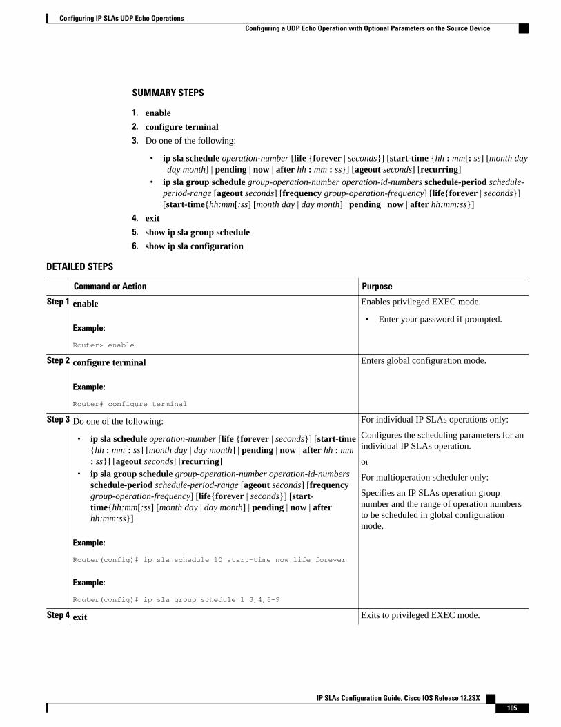
SUMMARY STEPS
1. enable
2. configure terminal
3. Do one of the following:
• ip sla schedule operation-number [life {forever | seconds}] [start-time {hh : mm[: ss] [month day| day month] | pending | now | after hh : mm : ss}] [ageout seconds] [recurring]
• ip sla group schedule group-operation-number operation-id-numbers schedule-period schedule-period-range [ageout seconds] [frequency group-operation-frequency] [life{forever | seconds}][start-time{hh:mm[:ss] [month day | day month] | pending | now | after hh:mm:ss}]
4. exit
5. show ip sla group schedule
6. show ip sla configuration
DETAILED STEPS
Command or Action Purpose
Step 1 enable
Example:
Router> enable
Enables privileged EXEC mode.
• Enter your password if prompted.
Step 2 configure terminal
Example:
Router# configure terminal
Enters global configuration mode.
Step 3 Do one of the following:
• ip sla schedule operation-number [life {forever | seconds}] [start-time{hh : mm[: ss] [month day | day month] | pending | now | after hh : mm: ss}] [ageout seconds] [recurring]
• ip sla group schedule group-operation-number operation-id-numbersschedule-period schedule-period-range [ageout seconds] [frequencygroup-operation-frequency] [life{forever | seconds}] [start-time{hh:mm[:ss] [month day | day month] | pending | now | afterhh:mm:ss}]
Example:
Router(config)# ip sla schedule 10 start-time now life forever
Example:
Router(config)# ip sla group schedule 1 3,4,6-9
For individual IP SLAs operations only:
Configures the scheduling parameters for anindividual IP SLAs operation.
or
For multioperation scheduler only:
Specifies an IP SLAs operation groupnumber and the range of operation numbersto be scheduled in global configurationmode.
Step 4 exit Exits to privileged EXEC mode.
Configuring IP SLAs UDP Echo OperationsConfiguring a UDP Echo Operation with Optional Parameters on the Source Device
IP SLAs Configuration Guide, Cisco IOS Release 12.2SX 105
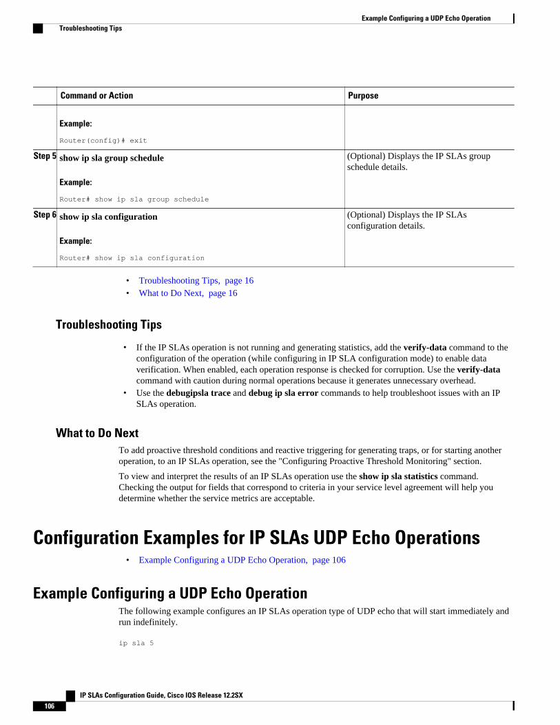
Command or Action Purpose
Example:
Router(config)# exit
Step 5 show ip sla group schedule
Example:
Router# show ip sla group schedule
(Optional) Displays the IP SLAs groupschedule details.
Step 6 show ip sla configuration
Example:
Router# show ip sla configuration
(Optional) Displays the IP SLAsconfiguration details.
• Troubleshooting Tips, page 16• What to Do Next, page 16
Troubleshooting Tips
• If the IP SLAs operation is not running and generating statistics, add the verify-data command to theconfiguration of the operation (while configuring in IP SLA configuration mode) to enable dataverification. When enabled, each operation response is checked for corruption. Use the verify-datacommand with caution during normal operations because it generates unnecessary overhead.
• Use the debugipsla trace and debug ip sla error commands to help troubleshoot issues with an IPSLAs operation.
What to Do NextTo add proactive threshold conditions and reactive triggering for generating traps, or for starting anotheroperation, to an IP SLAs operation, see the "Configuring Proactive Threshold Monitoring" section.
To view and interpret the results of an IP SLAs operation use the show ip sla statistics command.Checking the output for fields that correspond to criteria in your service level agreement will help youdetermine whether the service metrics are acceptable.
Configuration Examples for IP SLAs UDP Echo Operations• Example Configuring a UDP Echo Operation, page 106
Example Configuring a UDP Echo OperationThe following example configures an IP SLAs operation type of UDP echo that will start immediately andrun indefinitely.
ip sla 5
Example Configuring a UDP Echo Operation Troubleshooting Tips
IP SLAs Configuration Guide, Cisco IOS Release 12.2SX106
udp-echo 172.29.139.134 5000 frequency 30 request-data-size 160 tos 128 timeout 1000 tag FLL-ROip sla schedule 5 life forever start-time now
Additional ReferencesRelated Documents
Related Topic Document Title
Cisco IOS commands Cisco IOS Master Commands List, All Releases
Cisco IOS IP SLAs commands Cisco IOS IP SLAs Command Reference
Standards
Standards Title
No new or modified standards are supported by thisfeature, and support for existing standards has notbeen modified by this feature.
--
MIBs
MIBs MIBs Link
CISCO-RTTMON-MIB To locate and download MIBs for selectedplatforms, Cisco IOS releases, and feature sets, useCisco MIB Locator found at the following URL:
http://www.cisco.com/go/mibs
RFCs
RFCs Title
RFC 862 Echo Protocol
Technical Assistance
Description Link
The Cisco Support and Documentation websiteprovides online resources to downloaddocumentation, software, and tools. Use theseresources to install and configure the software andto troubleshoot and resolve technical issues withCisco products and technologies. Access to most
http://www.cisco.com/cisco/web/support/index.html
Configuring IP SLAs UDP Echo OperationsAdditional References
IP SLAs Configuration Guide, Cisco IOS Release 12.2SX 107
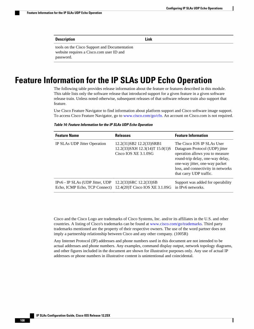
Description Link
tools on the Cisco Support and Documentationwebsite requires a Cisco.com user ID andpassword.
Feature Information for the IP SLAs UDP Echo OperationThe following table provides release information about the feature or features described in this module.This table lists only the software release that introduced support for a given feature in a given softwarerelease train. Unless noted otherwise, subsequent releases of that software release train also support thatfeature.
Use Cisco Feature Navigator to find information about platform support and Cisco software image support.To access Cisco Feature Navigator, go to www.cisco.com/go/cfn. An account on Cisco.com is not required.
Table 14: Feature Information for the IP SLAs UDP Echo Operation
Feature Name Releases Feature Information
IP SLAs UDP Jitter Operation 12.2(31)SB2 12.2(33)SRB112.2(33)SXH 12.3(14)T 15.0(1)SCisco IOS XE 3.1.0SG
The Cisco IOS IP SLAs UserDatagram Protocol (UDP) jitteroperation allows you to measureround-trip delay, one-way delay,one-way jitter, one-way packetloss, and connectivity in networksthat carry UDP traffic.
IPv6 - IP SLAs (UDP Jitter, UDPEcho, ICMP Echo, TCP Connect)
12.2(33)SRC 12.2(33)SB12.4(20)T Cisco IOS XE 3.1.0SG
Support was added for operabilityin IPv6 networks.
Cisco and the Cisco Logo are trademarks of Cisco Systems, Inc. and/or its affiliates in the U.S. and othercountries. A listing of Cisco's trademarks can be found at www.cisco.com/go/trademarks. Third partytrademarks mentioned are the property of their respective owners. The use of the word partner does notimply a partnership relationship between Cisco and any other company. (1005R)
Any Internet Protocol (IP) addresses and phone numbers used in this document are not intended to beactual addresses and phone numbers. Any examples, command display output, network topology diagrams,and other figures included in the document are shown for illustrative purposes only. Any use of actual IPaddresses or phone numbers in illustrative content is unintentional and coincidental.
Configuring IP SLAs UDP Echo Operations Feature Information for the IP SLAs UDP Echo Operation
IP SLAs Configuration Guide, Cisco IOS Release 12.2SX108
Configuring IP SLAs HTTP Operations
This module describes how to configure an IP Service Level Agreements (SLAs) HTTP operation tomonitor the response time between a Cisco device and an HTTP server to retrieve a web page. The IPSLAs HTTP operation supports both the normal GET requests and customer RAW requests. This modulealso demonstrates how the results of the HTTP operation can be displayed and analyzed to determine howan HTTP server is performing.
• Finding Feature Information, page 109• Restrictions for IP SLAs HTTP Operations, page 109• Information About IP SLAs HTTP Operations, page 109• How to Configure IP SLAs HTTP Operations, page 110• Configuration Examples for IP SLAs HTTP Operations, page 118• Additional References, page 119• Feature Information for IP SLAs HTTP Operations, page 120
Finding Feature InformationYour software release may not support all the features documented in this module. For the latest featureinformation and caveats, see the release notes for your platform and software release. To find informationabout the features documented in this module, and to see a list of the releases in which each feature issupported, see the Feature Information Table at the end of this document.
Use Cisco Feature Navigator to find information about platform support and Cisco software image support.To access Cisco Feature Navigator, go to www.cisco.com/go/cfn. An account on Cisco.com is not required.
Restrictions for IP SLAs HTTP Operations• IP SLAs HTTP operations support only HTTP/1.0.• HTTP/1.1 is not supported for any IP SLAs HTTP operation, including HTTP RAW requests.
Information About IP SLAs HTTP Operations• HTTP Operation, page 110
IP SLAs Configuration Guide, Cisco IOS Release 12.2SX 109
HTTP OperationThe HTTP operation measures the round-trip time (RTT) between a Cisco device and an HTTP server toretrieve a web page. The HTTP server response time measurements consist of three types:
• DNS lookup--RTT taken to perform domain name lookup.• TCP Connect--RTT taken to perform a TCP connection to the HTTP server.• HTTP transaction time--RTT taken to send a request and get a response from the HTTP server. The
operation retrieves only the home HTML page.
The DNS operation is performed first and the DNS RTT is measured. Once the domain name is found, aTCP Connect operation to the appropriate HTTP server is performed and the RTT for this operation ismeasured. The final operation is an HTTP request and the RTT to retrieve the home HTML page from theHTTP server is measured. One other measurement is made and called the time to first byte which measuresthe time from the start of the TCP Connect operation to the first HTML byte retrieved by the HTTPoperation. The total HTTP RTT is a sum of the DNS RTT, the TCP Connect RTT, and the HTTP RTT.
For GET requests, IP SLAs will format the request based on the specified URL. For RAW requests, IPSLAs requires the entire content of the HTTP request. When a RAW request is configured, the rawcommands are specified in HTTP RAW configuration mode. A RAW request is flexible and allows you tocontrol fields such as authentication. An HTTP request can be made through a proxy server.
The results of an HTTP operation can be useful in monitoring your web server performance levels bydetermining the RTT taken to retrieve a web page.
How to Configure IP SLAs HTTP Operations• Configuring an HTTP GET Operation on the Source Device, page 110
• Configuring an HTTP RAW Operation on the Source Device, page 115
• Scheduling IP SLAs Operations, page 104
Configuring an HTTP GET Operation on the Source Device
Note This operation does not require an IP SLAs Responder on the destination device.
Perform only one of the following tasks:
• Configuring a Basic HTTP GET Operation on the Source Device, page 110
• Configuring an HTTP GET Operation with Optional Parameters on the Source Device, page 112
Configuring a Basic HTTP GET Operation on the Source Device
HTTP Operation How to Configure IP SLAs HTTP Operations
IP SLAs Configuration Guide, Cisco IOS Release 12.2SX110
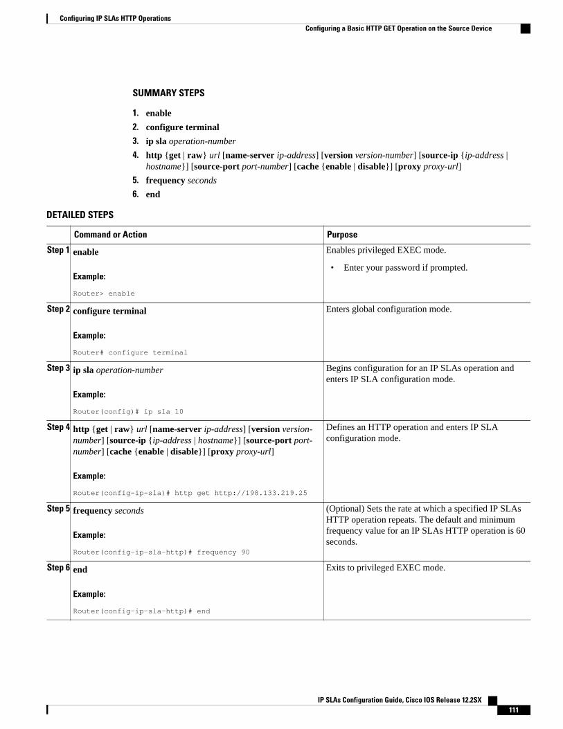
SUMMARY STEPS
1. enable
2. configure terminal
3. ip sla operation-number
4. http {get | raw} url [name-server ip-address] [version version-number] [source-ip {ip-address |hostname}] [source-port port-number] [cache {enable | disable}] [proxy proxy-url]
5. frequency seconds
6. end
DETAILED STEPS
Command or Action Purpose
Step 1 enable
Example:
Router> enable
Enables privileged EXEC mode.
• Enter your password if prompted.
Step 2 configure terminal
Example:
Router# configure terminal
Enters global configuration mode.
Step 3 ip sla operation-number
Example:
Router(config)# ip sla 10
Begins configuration for an IP SLAs operation andenters IP SLA configuration mode.
Step 4 http {get | raw} url [name-server ip-address] [version version-number] [source-ip {ip-address | hostname}] [source-port port-number] [cache {enable | disable}] [proxy proxy-url]
Example:
Router(config-ip-sla)# http get http://198.133.219.25
Defines an HTTP operation and enters IP SLAconfiguration mode.
Step 5 frequency seconds
Example:
Router(config-ip-sla-http)# frequency 90
(Optional) Sets the rate at which a specified IP SLAsHTTP operation repeats. The default and minimumfrequency value for an IP SLAs HTTP operation is 60seconds.
Step 6 end
Example:
Router(config-ip-sla-http)# end
Exits to privileged EXEC mode.
Configuring IP SLAs HTTP OperationsConfiguring a Basic HTTP GET Operation on the Source Device
IP SLAs Configuration Guide, Cisco IOS Release 12.2SX 111
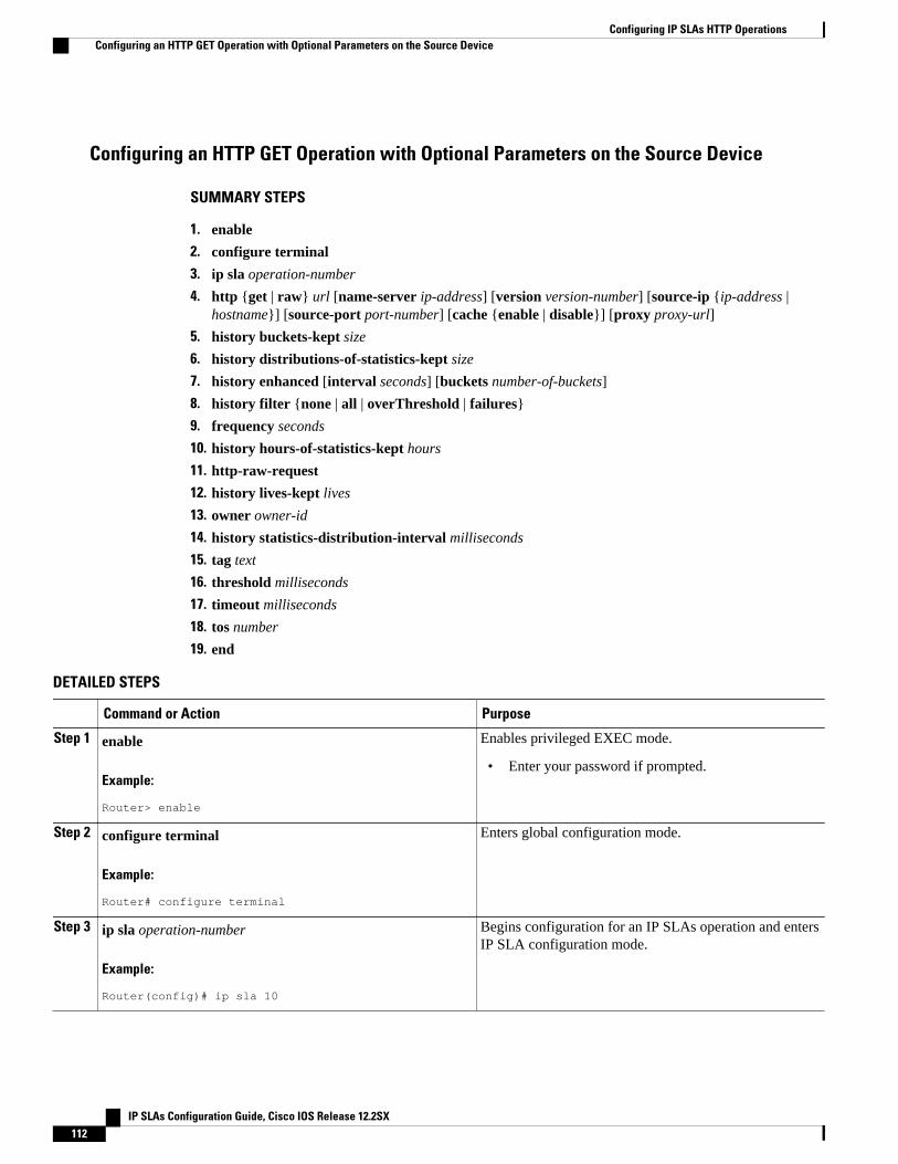
Configuring an HTTP GET Operation with Optional Parameters on the Source Device
SUMMARY STEPS
1. enable
2. configure terminal
3. ip sla operation-number
4. http {get | raw} url [name-server ip-address] [version version-number] [source-ip {ip-address |hostname}] [source-port port-number] [cache {enable | disable}] [proxy proxy-url]
5. history buckets-kept size
6. history distributions-of-statistics-kept size
7. history enhanced [interval seconds] [buckets number-of-buckets]
8. history filter {none | all | overThreshold | failures}
9. frequency seconds
10. history hours-of-statistics-kept hours
11. http-raw-request
12. history lives-kept lives
13. owner owner-id
14. history statistics-distribution-interval milliseconds
15. tag text
16. threshold milliseconds
17. timeout milliseconds
18. tos number
19. end
DETAILED STEPS
Command or Action Purpose
Step 1 enable
Example:
Router> enable
Enables privileged EXEC mode.
• Enter your password if prompted.
Step 2 configure terminal
Example:
Router# configure terminal
Enters global configuration mode.
Step 3 ip sla operation-number
Example:
Router(config)# ip sla 10
Begins configuration for an IP SLAs operation and entersIP SLA configuration mode.
Configuring IP SLAs HTTP Operations Configuring an HTTP GET Operation with Optional Parameters on the Source Device
IP SLAs Configuration Guide, Cisco IOS Release 12.2SX112
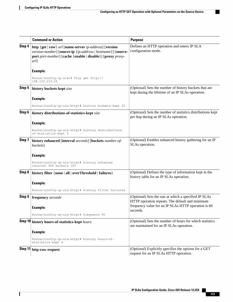
Command or Action Purpose
Step 4 http {get | raw} url [name-server ip-address] [versionversion-number] [source-ip {ip-address | hostname}] [source-port port-number] [cache {enable | disable}] [proxy proxy-url]
Example:
Router(config-ip-sla)# http get http://198.133.219.25
Defines an HTTP operation and enters IP SLAconfiguration mode.
Step 5 history buckets-kept size
Example:
Router(config-ip-sla-http)# history buckets-kept 25
(Optional) Sets the number of history buckets that arekept during the lifetime of an IP SLAs operation.
Step 6 history distributions-of-statistics-kept size
Example:
Router(config-ip-sla-http)# history distributions-of-statistics-kept 5
(Optional) Sets the number of statistics distributions keptper hop during an IP SLAs operation.
Step 7 history enhanced [interval seconds] [buckets number-of-buckets]
Example:
Router(config-ip-sla-http)# history enhanced interval 900 buckets 100
(Optional) Enables enhanced history gathering for an IPSLAs operation.
Step 8 history filter {none | all | overThreshold | failures}
Example:
Router(config-ip-sla-http)# history filter failures
(Optional) Defines the type of information kept in thehistory table for an IP SLAs operation.
Step 9 frequency seconds
Example:
Router(config-ip-sla-http)# frequency 90
(Optional) Sets the rate at which a specified IP SLAsHTTP operation repeats. The default and minimumfrequency value for an IP SLAs HTTP operation is 60seconds.
Step 10 history hours-of-statistics-kept hours
Example:
Router(config-ip-sla-http)# history hours-of-statistics-kept 4
(Optional) Sets the number of hours for which statisticsare maintained for an IP SLAs operation.
Step 11 http-raw-request (Optional) Explicitly specifies the options for a GETrequest for an IP SLAs HTTP operation.
Configuring IP SLAs HTTP OperationsConfiguring an HTTP GET Operation with Optional Parameters on the Source Device
IP SLAs Configuration Guide, Cisco IOS Release 12.2SX 113
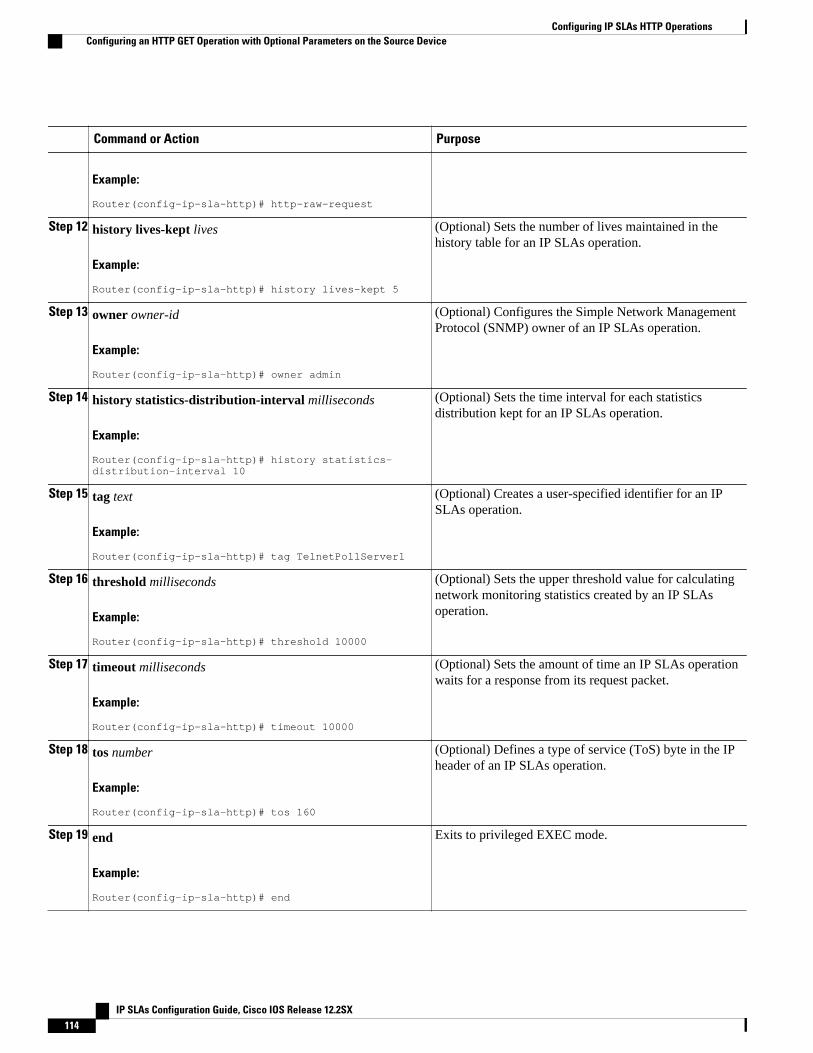
Command or Action Purpose
Example:
Router(config-ip-sla-http)# http-raw-request
Step 12 history lives-kept lives
Example:
Router(config-ip-sla-http)# history lives-kept 5
(Optional) Sets the number of lives maintained in thehistory table for an IP SLAs operation.
Step 13 owner owner-id
Example:
Router(config-ip-sla-http)# owner admin
(Optional) Configures the Simple Network ManagementProtocol (SNMP) owner of an IP SLAs operation.
Step 14 history statistics-distribution-interval milliseconds
Example:
Router(config-ip-sla-http)# history statistics-distribution-interval 10
(Optional) Sets the time interval for each statisticsdistribution kept for an IP SLAs operation.
Step 15 tag text
Example:
Router(config-ip-sla-http)# tag TelnetPollServer1
(Optional) Creates a user-specified identifier for an IPSLAs operation.
Step 16 threshold milliseconds
Example:
Router(config-ip-sla-http)# threshold 10000
(Optional) Sets the upper threshold value for calculatingnetwork monitoring statistics created by an IP SLAsoperation.
Step 17 timeout milliseconds
Example:
Router(config-ip-sla-http)# timeout 10000
(Optional) Sets the amount of time an IP SLAs operationwaits for a response from its request packet.
Step 18 tos number
Example:
Router(config-ip-sla-http)# tos 160
(Optional) Defines a type of service (ToS) byte in the IPheader of an IP SLAs operation.
Step 19 end
Example:
Router(config-ip-sla-http)# end
Exits to privileged EXEC mode.
Configuring IP SLAs HTTP Operations Configuring an HTTP GET Operation with Optional Parameters on the Source Device
IP SLAs Configuration Guide, Cisco IOS Release 12.2SX114
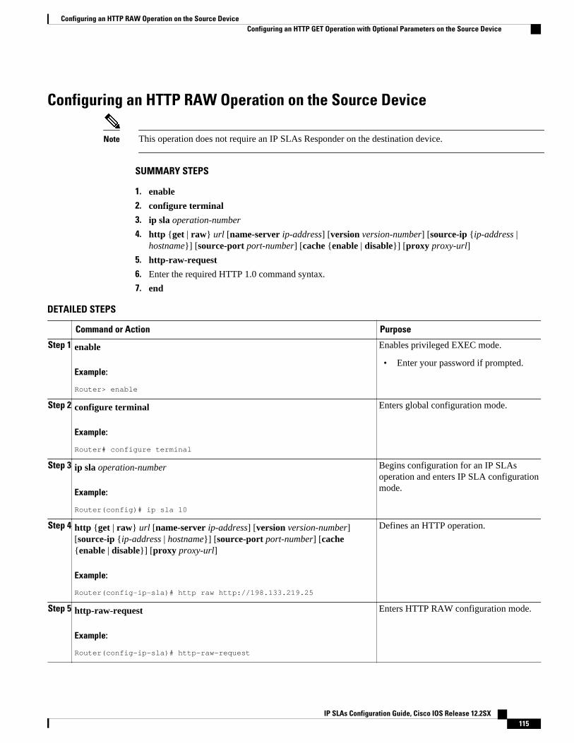
Configuring an HTTP RAW Operation on the Source Device
Note This operation does not require an IP SLAs Responder on the destination device.
SUMMARY STEPS
1. enable
2. configure terminal
3. ip sla operation-number
4. http {get | raw} url [name-server ip-address] [version version-number] [source-ip {ip-address |hostname}] [source-port port-number] [cache {enable | disable}] [proxy proxy-url]
5. http-raw-request
6. Enter the required HTTP 1.0 command syntax.
7. end
DETAILED STEPS
Command or Action Purpose
Step 1 enable
Example:
Router> enable
Enables privileged EXEC mode.
• Enter your password if prompted.
Step 2 configure terminal
Example:
Router# configure terminal
Enters global configuration mode.
Step 3 ip sla operation-number
Example:
Router(config)# ip sla 10
Begins configuration for an IP SLAsoperation and enters IP SLA configurationmode.
Step 4 http {get | raw} url [name-server ip-address] [version version-number][source-ip {ip-address | hostname}] [source-port port-number] [cache{enable | disable}] [proxy proxy-url]
Example:
Router(config-ip-sla)# http raw http://198.133.219.25
Defines an HTTP operation.
Step 5 http-raw-request
Example:
Router(config-ip-sla)# http-raw-request
Enters HTTP RAW configuration mode.
Configuring an HTTP RAW Operation on the Source DeviceConfiguring an HTTP GET Operation with Optional Parameters on the Source Device
IP SLAs Configuration Guide, Cisco IOS Release 12.2SX 115
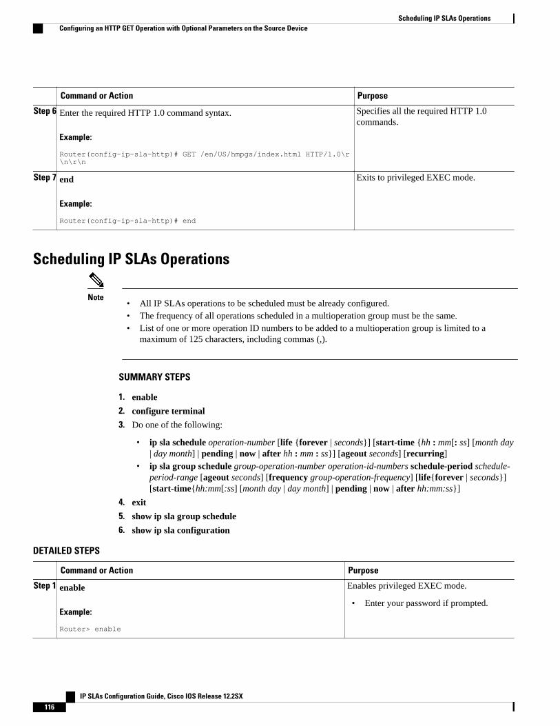
Command or Action Purpose
Step 6 Enter the required HTTP 1.0 command syntax.
Example:
Router(config-ip-sla-http)# GET /en/US/hmpgs/index.html HTTP/1.0\r\n\r\n
Specifies all the required HTTP 1.0commands.
Step 7 end
Example:
Router(config-ip-sla-http)# end
Exits to privileged EXEC mode.
Scheduling IP SLAs Operations
Note• All IP SLAs operations to be scheduled must be already configured.• The frequency of all operations scheduled in a multioperation group must be the same.• List of one or more operation ID numbers to be added to a multioperation group is limited to a
maximum of 125 characters, including commas (,).
SUMMARY STEPS
1. enable
2. configure terminal
3. Do one of the following:
• ip sla schedule operation-number [life {forever | seconds}] [start-time {hh : mm[: ss] [month day| day month] | pending | now | after hh : mm : ss}] [ageout seconds] [recurring]
• ip sla group schedule group-operation-number operation-id-numbers schedule-period schedule-period-range [ageout seconds] [frequency group-operation-frequency] [life{forever | seconds}][start-time{hh:mm[:ss] [month day | day month] | pending | now | after hh:mm:ss}]
4. exit
5. show ip sla group schedule
6. show ip sla configuration
DETAILED STEPS
Command or Action Purpose
Step 1 enable
Example:
Router> enable
Enables privileged EXEC mode.
• Enter your password if prompted.
Scheduling IP SLAs Operations Configuring an HTTP GET Operation with Optional Parameters on the Source Device
IP SLAs Configuration Guide, Cisco IOS Release 12.2SX116
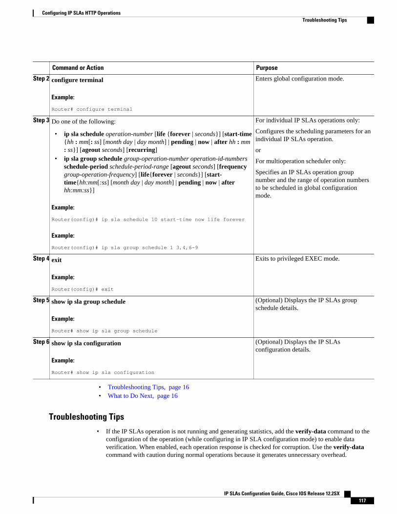
Command or Action Purpose
Step 2 configure terminal
Example:
Router# configure terminal
Enters global configuration mode.
Step 3 Do one of the following:
• ip sla schedule operation-number [life {forever | seconds}] [start-time{hh : mm[: ss] [month day | day month] | pending | now | after hh : mm: ss}] [ageout seconds] [recurring]
• ip sla group schedule group-operation-number operation-id-numbersschedule-period schedule-period-range [ageout seconds] [frequencygroup-operation-frequency] [life{forever | seconds}] [start-time{hh:mm[:ss] [month day | day month] | pending | now | afterhh:mm:ss}]
Example:
Router(config)# ip sla schedule 10 start-time now life forever
Example:
Router(config)# ip sla group schedule 1 3,4,6-9
For individual IP SLAs operations only:
Configures the scheduling parameters for anindividual IP SLAs operation.
or
For multioperation scheduler only:
Specifies an IP SLAs operation groupnumber and the range of operation numbersto be scheduled in global configurationmode.
Step 4 exit
Example:
Router(config)# exit
Exits to privileged EXEC mode.
Step 5 show ip sla group schedule
Example:
Router# show ip sla group schedule
(Optional) Displays the IP SLAs groupschedule details.
Step 6 show ip sla configuration
Example:
Router# show ip sla configuration
(Optional) Displays the IP SLAsconfiguration details.
• Troubleshooting Tips, page 16• What to Do Next, page 16
Troubleshooting Tips
• If the IP SLAs operation is not running and generating statistics, add the verify-data command to theconfiguration of the operation (while configuring in IP SLA configuration mode) to enable dataverification. When enabled, each operation response is checked for corruption. Use the verify-datacommand with caution during normal operations because it generates unnecessary overhead.
Configuring IP SLAs HTTP OperationsTroubleshooting Tips
IP SLAs Configuration Guide, Cisco IOS Release 12.2SX 117
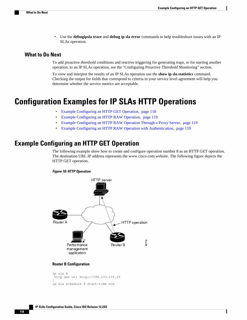
• Use the debugipsla trace and debug ip sla error commands to help troubleshoot issues with an IPSLAs operation.
What to Do NextTo add proactive threshold conditions and reactive triggering for generating traps, or for starting anotheroperation, to an IP SLAs operation, see the "Configuring Proactive Threshold Monitoring" section.
To view and interpret the results of an IP SLAs operation use the show ip sla statistics command.Checking the output for fields that correspond to criteria in your service level agreement will help youdetermine whether the service metrics are acceptable.
Configuration Examples for IP SLAs HTTP Operations• Example Configuring an HTTP GET Operation, page 118• Example Configuring an HTTP RAW Operation, page 119• Example Configuring an HTTP RAW Operation Through a Proxy Server, page 119• Example Configuring an HTTP RAW Operation with Authentication, page 119
Example Configuring an HTTP GET OperationThe following example show how to create and configure operation number 8 as an HTTP GET operation.The destination URL IP address represents the www.cisco.com website. The following figure depicts theHTTP GET operation.
Figure 10: HTTP Operation
Router B Configuration
ip sla 8 http get url http://198.133.219.25!ip sla schedule 8 start-time now
Example Configuring an HTTP GET Operation What to Do Next
IP SLAs Configuration Guide, Cisco IOS Release 12.2SX118
Example Configuring an HTTP RAW OperationThe following example shows how to configure an HTTP RAW operation. To use the RAW commands,enter HTTP RAW configuration mode by using the http-raw-request command in IP SLA configurationmode. The IP SLA HTTP RAW configuration mode is indicated by the (config-ip-sla-http) router prompt.
ip sla 8 http raw url http://198.133.219.25 http-raw-request GET /en/US/hmpgs/index.html HTTP/1.0\r\n \r\n endip sla schedule 8 life forever start-time now
Example Configuring an HTTP RAW Operation Through a Proxy ServerThe following example shows how to configure an HTTP RAW operation through a proxy server. Theproxy server is www.proxy.cisco.com and the HTTP server is www.yahoo.com.
ip sla 8 http raw url http://www.proxy.cisco.com http-raw-request GET http://www.yahoo.com HTTP/1.0\r\n \r\n endip sla schedule 8 life forever start-time now
Example Configuring an HTTP RAW Operation with AuthenticationThe following example shows how to configure an HTTP RAW operation with authentication.
ip sla 8 http raw url http://site-test.cisco.com http-raw-request GET /lab/index.html HTTP/1.0\r\n Authorization: Basic btNpdGT4biNvoZe=\r\n \r\n endip sla schedule 8 life forever start-time now
Additional ReferencesRelated Documents
Related Topic Document Title
Cisco IOS commands Cisco IOS Master Commands List, All Releases
Cisco IOS IP SLAs commands Cisco IOS IP SLAs Command Reference
Cisco IOS IP SLAs: general information Cisco IOS IP SLAs Overview chapter of the CiscoIOS IP SLAs Configuration Guide.
Example Configuring an HTTP RAW OperationAdditional References
IP SLAs Configuration Guide, Cisco IOS Release 12.2SX 119
Standards
Standards Title
No new or modified standards are supported by thisfeature, and support for existing standards has notbeen modified by this feature.
--
MIBs
MIBs MIBs Link
CISCO-RTTMON-MIB To locate and download MIBs for selectedplatforms, Cisco IOS releases, and feature sets, useCisco MIB Locator found at the following URL:
http://www.cisco.com/go/mibs
RFCs
RFCs Title
No new or modified RFCs are supported by thisfeature, and support for existing RFCs has not beenmodified by this feature.
--
Technical Assistance
Description Link
The Cisco Support and Documentation websiteprovides online resources to downloaddocumentation, software, and tools. Use theseresources to install and configure the software andto troubleshoot and resolve technical issues withCisco products and technologies. Access to mosttools on the Cisco Support and Documentationwebsite requires a Cisco.com user ID andpassword.
http://www.cisco.com/cisco/web/support/index.html
Feature Information for IP SLAs HTTP OperationsThe following table provides release information about the feature or features described in this module.This table lists only the software release that introduced support for a given feature in a given softwarerelease train. Unless noted otherwise, subsequent releases of that software release train also support thatfeature.
Use Cisco Feature Navigator to find information about platform support and Cisco software image support.To access Cisco Feature Navigator, go to www.cisco.com/go/cfn. An account on Cisco.com is not required.
Configuring IP SLAs HTTP Operations Feature Information for IP SLAs HTTP Operations
IP SLAs Configuration Guide, Cisco IOS Release 12.2SX120
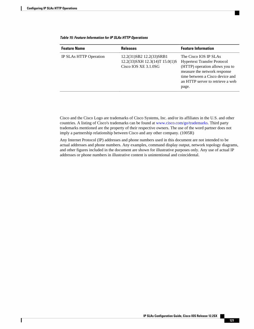
Table 15: Feature Information for IP SLAs HTTP Operations
Feature Name Releases Feature Information
IP SLAs HTTP Operation 12.2(31)SB2 12.2(33)SRB112.2(33)SXH 12.3(14)T 15.0(1)SCisco IOS XE 3.1.0SG
The Cisco IOS IP SLAsHypertext Transfer Protocol(HTTP) operation allows you tomeasure the network responsetime between a Cisco device andan HTTP server to retrieve a webpage.
Cisco and the Cisco Logo are trademarks of Cisco Systems, Inc. and/or its affiliates in the U.S. and othercountries. A listing of Cisco's trademarks can be found at www.cisco.com/go/trademarks. Third partytrademarks mentioned are the property of their respective owners. The use of the word partner does notimply a partnership relationship between Cisco and any other company. (1005R)
Any Internet Protocol (IP) addresses and phone numbers used in this document are not intended to beactual addresses and phone numbers. Any examples, command display output, network topology diagrams,and other figures included in the document are shown for illustrative purposes only. Any use of actual IPaddresses or phone numbers in illustrative content is unintentional and coincidental.
Configuring IP SLAs HTTP Operations
IP SLAs Configuration Guide, Cisco IOS Release 12.2SX 121
Example Configuring an HTTP RAW Operation with Authentication
IP SLAs Configuration Guide, Cisco IOS Release 12.2SX122
Configuring IP SLAs TCP Connect Operations
This module describes how to configure an IP Service Level Agreements (SLAs) TCP Connect operationto measure the response time taken to perform a TCP Connect operation between a Cisco router anddevices using IPv4 or IPv6. TCP Connect accuracy is enhanced by using the IP SLAs Responder at thedestination Cisco router. This module also demonstrates how the results of the TCP Connect operation canbe displayed and analyzed to determine how the connection times to servers and hosts within yournetwork can affect IP service levels. The TCP Connect operation is useful for measuring response timesfor a server used for a particular application or connectivity testing for server availability.
• Finding Feature Information, page 123• Information About the IP SLAs TCP Connect Operation, page 123• How to Configure the IP SLAs TCP Connect Operation, page 124• Configuration Examples for IP SLAs TCP Connect Operations, page 133• Additional References, page 133• Feature Information for the IP SLAs TCP Connect Operation, page 134
Finding Feature InformationYour software release may not support all the features documented in this module. For the latest featureinformation and caveats, see the release notes for your platform and software release. To find informationabout the features documented in this module, and to see a list of the releases in which each feature issupported, see the Feature Information Table at the end of this document.
Use Cisco Feature Navigator to find information about platform support and Cisco software image support.To access Cisco Feature Navigator, go to www.cisco.com/go/cfn. An account on Cisco.com is not required.
Information About the IP SLAs TCP Connect Operation• TCP Connect Operation, page 123
TCP Connect OperationThe IP SLAs TCP Connect operation measures the response time taken to perform a TCP Connectoperation between a Cisco router and devices using IP. TCP is a transport layer (Layer 4) Internet protocolthat provides reliable full-duplex data transmission. The destination device can be any device using IP or anIP SLAs Responder.
IP SLAs Configuration Guide, Cisco IOS Release 12.2SX 123
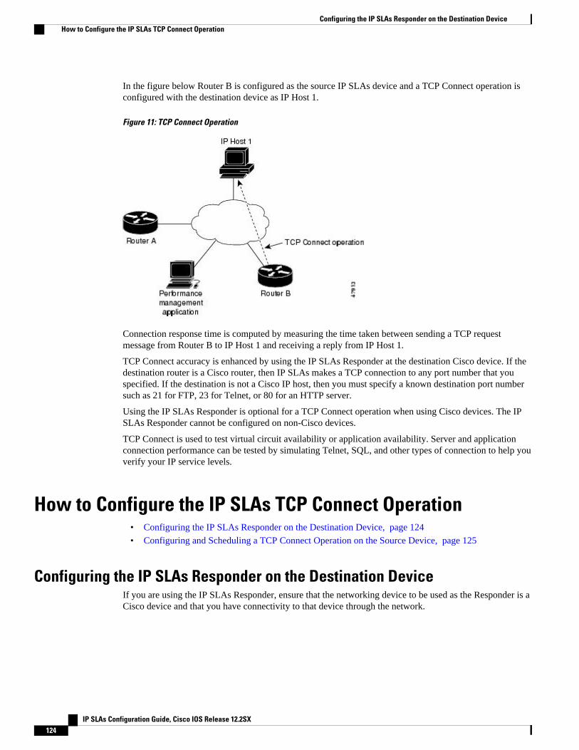
In the figure below Router B is configured as the source IP SLAs device and a TCP Connect operation isconfigured with the destination device as IP Host 1.
Figure 11: TCP Connect Operation
Connection response time is computed by measuring the time taken between sending a TCP requestmessage from Router B to IP Host 1 and receiving a reply from IP Host 1.
TCP Connect accuracy is enhanced by using the IP SLAs Responder at the destination Cisco device. If thedestination router is a Cisco router, then IP SLAs makes a TCP connection to any port number that youspecified. If the destination is not a Cisco IP host, then you must specify a known destination port numbersuch as 21 for FTP, 23 for Telnet, or 80 for an HTTP server.
Using the IP SLAs Responder is optional for a TCP Connect operation when using Cisco devices. The IPSLAs Responder cannot be configured on non-Cisco devices.
TCP Connect is used to test virtual circuit availability or application availability. Server and applicationconnection performance can be tested by simulating Telnet, SQL, and other types of connection to help youverify your IP service levels.
How to Configure the IP SLAs TCP Connect Operation• Configuring the IP SLAs Responder on the Destination Device, page 124
• Configuring and Scheduling a TCP Connect Operation on the Source Device, page 125
Configuring the IP SLAs Responder on the Destination DeviceIf you are using the IP SLAs Responder, ensure that the networking device to be used as the Responder is aCisco device and that you have connectivity to that device through the network.
Configuring the IP SLAs Responder on the Destination Device How to Configure the IP SLAs TCP Connect Operation
IP SLAs Configuration Guide, Cisco IOS Release 12.2SX124
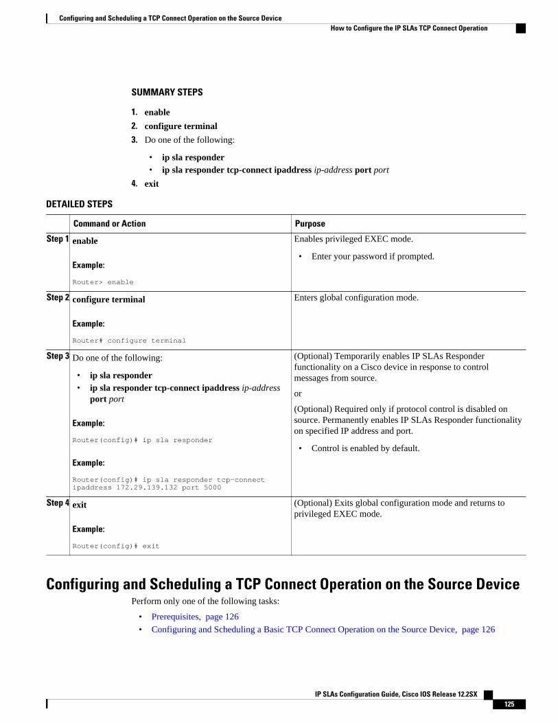
SUMMARY STEPS
1. enable
2. configure terminal
3. Do one of the following:
• ip sla responder• ip sla responder tcp-connect ipaddress ip-address port port
4. exit
DETAILED STEPS
Command or Action Purpose
Step 1 enable
Example:
Router> enable
Enables privileged EXEC mode.
• Enter your password if prompted.
Step 2 configure terminal
Example:
Router# configure terminal
Enters global configuration mode.
Step 3 Do one of the following:
• ip sla responder• ip sla responder tcp-connect ipaddress ip-address
port port
Example:
Router(config)# ip sla responder
Example:
Router(config)# ip sla responder tcp-connect ipaddress 172.29.139.132 port 5000
(Optional) Temporarily enables IP SLAs Responderfunctionality on a Cisco device in response to controlmessages from source.
or
(Optional) Required only if protocol control is disabled onsource. Permanently enables IP SLAs Responder functionalityon specified IP address and port.
• Control is enabled by default.
Step 4 exit
Example:
Router(config)# exit
(Optional) Exits global configuration mode and returns toprivileged EXEC mode.
Configuring and Scheduling a TCP Connect Operation on the Source DevicePerform only one of the following tasks:
• Prerequisites, page 126
• Configuring and Scheduling a Basic TCP Connect Operation on the Source Device, page 126
Configuring and Scheduling a TCP Connect Operation on the Source DeviceHow to Configure the IP SLAs TCP Connect Operation
IP SLAs Configuration Guide, Cisco IOS Release 12.2SX 125
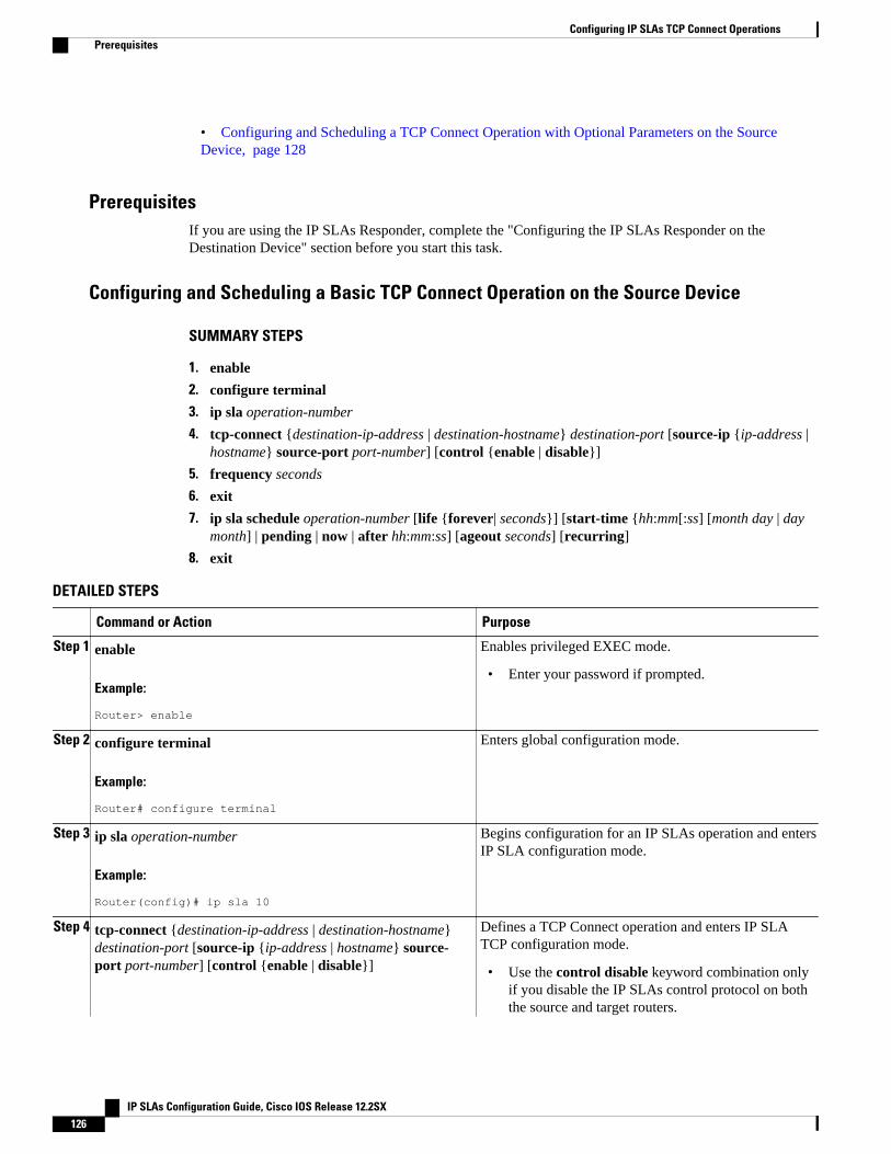
• Configuring and Scheduling a TCP Connect Operation with Optional Parameters on the SourceDevice, page 128
PrerequisitesIf you are using the IP SLAs Responder, complete the "Configuring the IP SLAs Responder on theDestination Device" section before you start this task.
Configuring and Scheduling a Basic TCP Connect Operation on the Source Device
SUMMARY STEPS
1. enable
2. configure terminal
3. ip sla operation-number
4. tcp-connect {destination-ip-address | destination-hostname} destination-port [source-ip {ip-address |hostname} source-port port-number] [control {enable | disable}]
5. frequency seconds
6. exit
7. ip sla schedule operation-number [life {forever| seconds}] [start-time {hh:mm[:ss] [month day | daymonth] | pending | now | after hh:mm:ss] [ageout seconds] [recurring]
8. exit
DETAILED STEPS
Command or Action Purpose
Step 1 enable
Example:
Router> enable
Enables privileged EXEC mode.
• Enter your password if prompted.
Step 2 configure terminal
Example:
Router# configure terminal
Enters global configuration mode.
Step 3 ip sla operation-number
Example:
Router(config)# ip sla 10
Begins configuration for an IP SLAs operation and entersIP SLA configuration mode.
Step 4 tcp-connect {destination-ip-address | destination-hostname}destination-port [source-ip {ip-address | hostname} source-port port-number] [control {enable | disable}]
Defines a TCP Connect operation and enters IP SLATCP configuration mode.
• Use the control disable keyword combination onlyif you disable the IP SLAs control protocol on boththe source and target routers.
Configuring IP SLAs TCP Connect Operations Prerequisites
IP SLAs Configuration Guide, Cisco IOS Release 12.2SX126
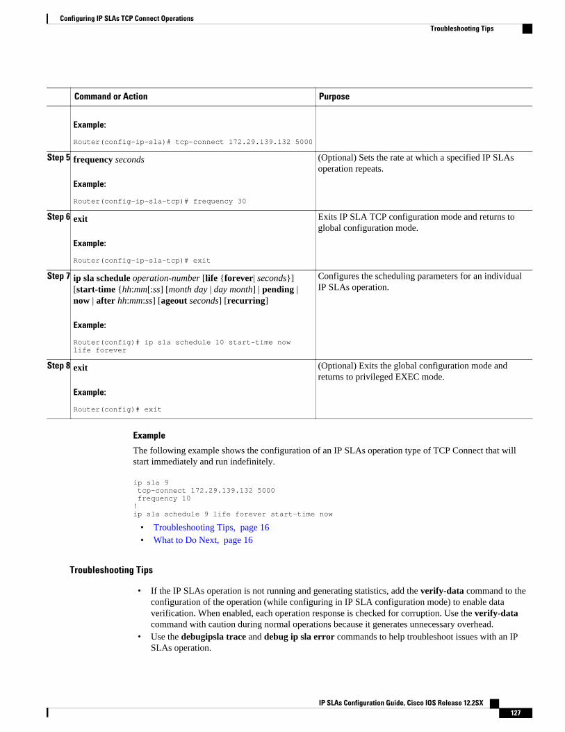
Command or Action Purpose
Example:
Router(config-ip-sla)# tcp-connect 172.29.139.132 5000
Step 5 frequency seconds
Example:
Router(config-ip-sla-tcp)# frequency 30
(Optional) Sets the rate at which a specified IP SLAsoperation repeats.
Step 6 exit
Example:
Router(config-ip-sla-tcp)# exit
Exits IP SLA TCP configuration mode and returns toglobal configuration mode.
Step 7 ip sla schedule operation-number [life {forever| seconds}][start-time {hh:mm[:ss] [month day | day month] | pending |now | after hh:mm:ss] [ageout seconds] [recurring]
Example:
Router(config)# ip sla schedule 10 start-time now life forever
Configures the scheduling parameters for an individualIP SLAs operation.
Step 8 exit
Example:
Router(config)# exit
(Optional) Exits the global configuration mode andreturns to privileged EXEC mode.
Example
The following example shows the configuration of an IP SLAs operation type of TCP Connect that willstart immediately and run indefinitely.
ip sla 9 tcp-connect 172.29.139.132 5000 frequency 10!ip sla schedule 9 life forever start-time now
• Troubleshooting Tips, page 16• What to Do Next, page 16
Troubleshooting Tips
• If the IP SLAs operation is not running and generating statistics, add the verify-data command to theconfiguration of the operation (while configuring in IP SLA configuration mode) to enable dataverification. When enabled, each operation response is checked for corruption. Use the verify-datacommand with caution during normal operations because it generates unnecessary overhead.
• Use the debugipsla trace and debug ip sla error commands to help troubleshoot issues with an IPSLAs operation.
Configuring IP SLAs TCP Connect OperationsTroubleshooting Tips
IP SLAs Configuration Guide, Cisco IOS Release 12.2SX 127
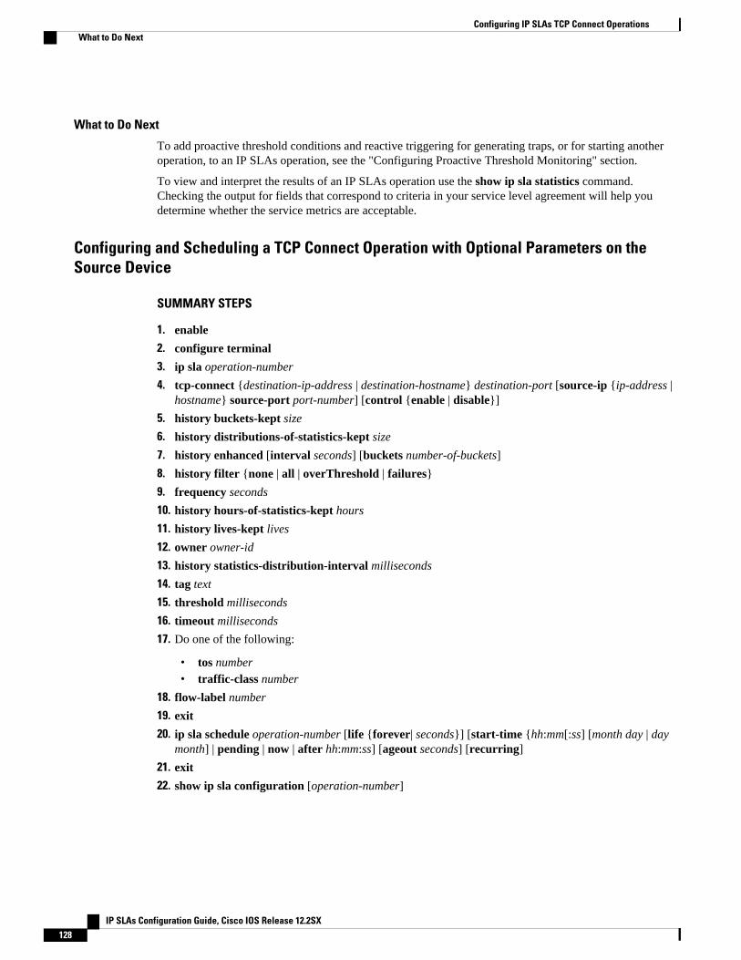
What to Do Next
To add proactive threshold conditions and reactive triggering for generating traps, or for starting anotheroperation, to an IP SLAs operation, see the "Configuring Proactive Threshold Monitoring" section.
To view and interpret the results of an IP SLAs operation use the show ip sla statistics command.Checking the output for fields that correspond to criteria in your service level agreement will help youdetermine whether the service metrics are acceptable.
Configuring and Scheduling a TCP Connect Operation with Optional Parameters on theSource Device
SUMMARY STEPS
1. enable
2. configure terminal
3. ip sla operation-number
4. tcp-connect {destination-ip-address | destination-hostname} destination-port [source-ip {ip-address |hostname} source-port port-number] [control {enable | disable}]
5. history buckets-kept size
6. history distributions-of-statistics-kept size
7. history enhanced [interval seconds] [buckets number-of-buckets]
8. history filter {none | all | overThreshold | failures}
9. frequency seconds
10. history hours-of-statistics-kept hours
11. history lives-kept lives
12. owner owner-id
13. history statistics-distribution-interval milliseconds
14. tag text
15. threshold milliseconds
16. timeout milliseconds
17. Do one of the following:
• tos number• traffic-class number
18. flow-label number
19. exit
20. ip sla schedule operation-number [life {forever| seconds}] [start-time {hh:mm[:ss] [month day | daymonth] | pending | now | after hh:mm:ss] [ageout seconds] [recurring]
21. exit
22. show ip sla configuration [operation-number]
Configuring IP SLAs TCP Connect Operations What to Do Next
IP SLAs Configuration Guide, Cisco IOS Release 12.2SX128
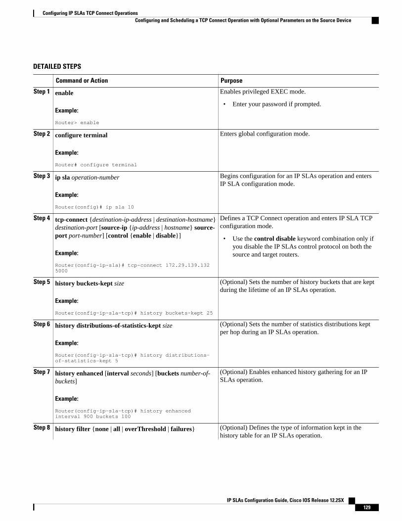
DETAILED STEPS
Command or Action Purpose
Step 1 enable
Example:
Router> enable
Enables privileged EXEC mode.
• Enter your password if prompted.
Step 2 configure terminal
Example:
Router# configure terminal
Enters global configuration mode.
Step 3 ip sla operation-number
Example:
Router(config)# ip sla 10
Begins configuration for an IP SLAs operation and entersIP SLA configuration mode.
Step 4 tcp-connect {destination-ip-address | destination-hostname}destination-port [source-ip {ip-address | hostname} source-port port-number] [control {enable | disable}]
Example:
Router(config-ip-sla)# tcp-connect 172.29.139.132 5000
Defines a TCP Connect operation and enters IP SLA TCPconfiguration mode.
• Use the control disable keyword combination only ifyou disable the IP SLAs control protocol on both thesource and target routers.
Step 5 history buckets-kept size
Example:
Router(config-ip-sla-tcp)# history buckets-kept 25
(Optional) Sets the number of history buckets that are keptduring the lifetime of an IP SLAs operation.
Step 6 history distributions-of-statistics-kept size
Example:
Router(config-ip-sla-tcp)# history distributions-of-statistics-kept 5
(Optional) Sets the number of statistics distributions keptper hop during an IP SLAs operation.
Step 7 history enhanced [interval seconds] [buckets number-of-buckets]
Example:
Router(config-ip-sla-tcp)# history enhanced interval 900 buckets 100
(Optional) Enables enhanced history gathering for an IPSLAs operation.
Step 8 history filter {none | all | overThreshold | failures} (Optional) Defines the type of information kept in thehistory table for an IP SLAs operation.
Configuring IP SLAs TCP Connect OperationsConfiguring and Scheduling a TCP Connect Operation with Optional Parameters on the Source Device
IP SLAs Configuration Guide, Cisco IOS Release 12.2SX 129
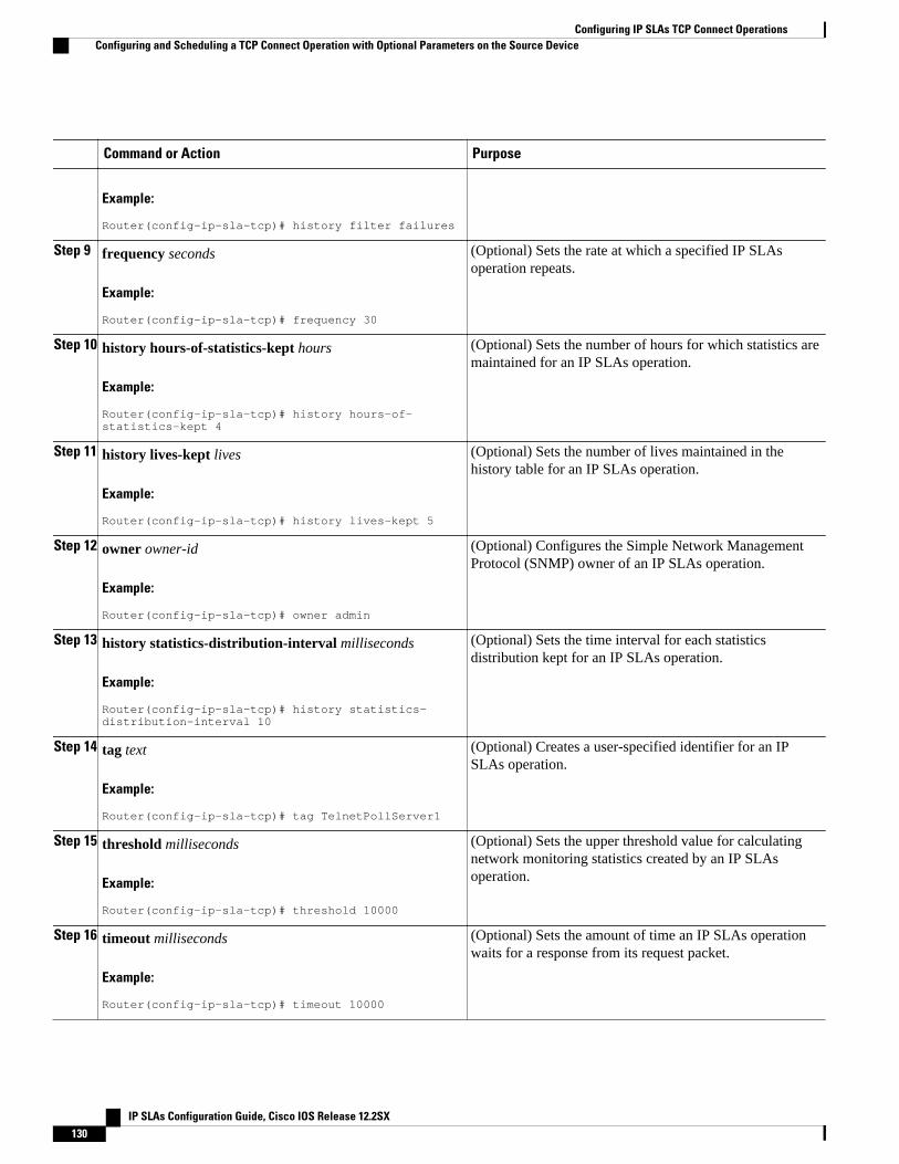
Command or Action Purpose
Example:
Router(config-ip-sla-tcp)# history filter failures
Step 9 frequency seconds
Example:
Router(config-ip-sla-tcp)# frequency 30
(Optional) Sets the rate at which a specified IP SLAsoperation repeats.
Step 10 history hours-of-statistics-kept hours
Example:
Router(config-ip-sla-tcp)# history hours-of-statistics-kept 4
(Optional) Sets the number of hours for which statistics aremaintained for an IP SLAs operation.
Step 11 history lives-kept lives
Example:
Router(config-ip-sla-tcp)# history lives-kept 5
(Optional) Sets the number of lives maintained in thehistory table for an IP SLAs operation.
Step 12 owner owner-id
Example:
Router(config-ip-sla-tcp)# owner admin
(Optional) Configures the Simple Network ManagementProtocol (SNMP) owner of an IP SLAs operation.
Step 13 history statistics-distribution-interval milliseconds
Example:
Router(config-ip-sla-tcp)# history statistics-distribution-interval 10
(Optional) Sets the time interval for each statisticsdistribution kept for an IP SLAs operation.
Step 14 tag text
Example:
Router(config-ip-sla-tcp)# tag TelnetPollServer1
(Optional) Creates a user-specified identifier for an IPSLAs operation.
Step 15 threshold milliseconds
Example:
Router(config-ip-sla-tcp)# threshold 10000
(Optional) Sets the upper threshold value for calculatingnetwork monitoring statistics created by an IP SLAsoperation.
Step 16 timeout milliseconds
Example:
Router(config-ip-sla-tcp)# timeout 10000
(Optional) Sets the amount of time an IP SLAs operationwaits for a response from its request packet.
Configuring IP SLAs TCP Connect Operations Configuring and Scheduling a TCP Connect Operation with Optional Parameters on the Source Device
IP SLAs Configuration Guide, Cisco IOS Release 12.2SX130
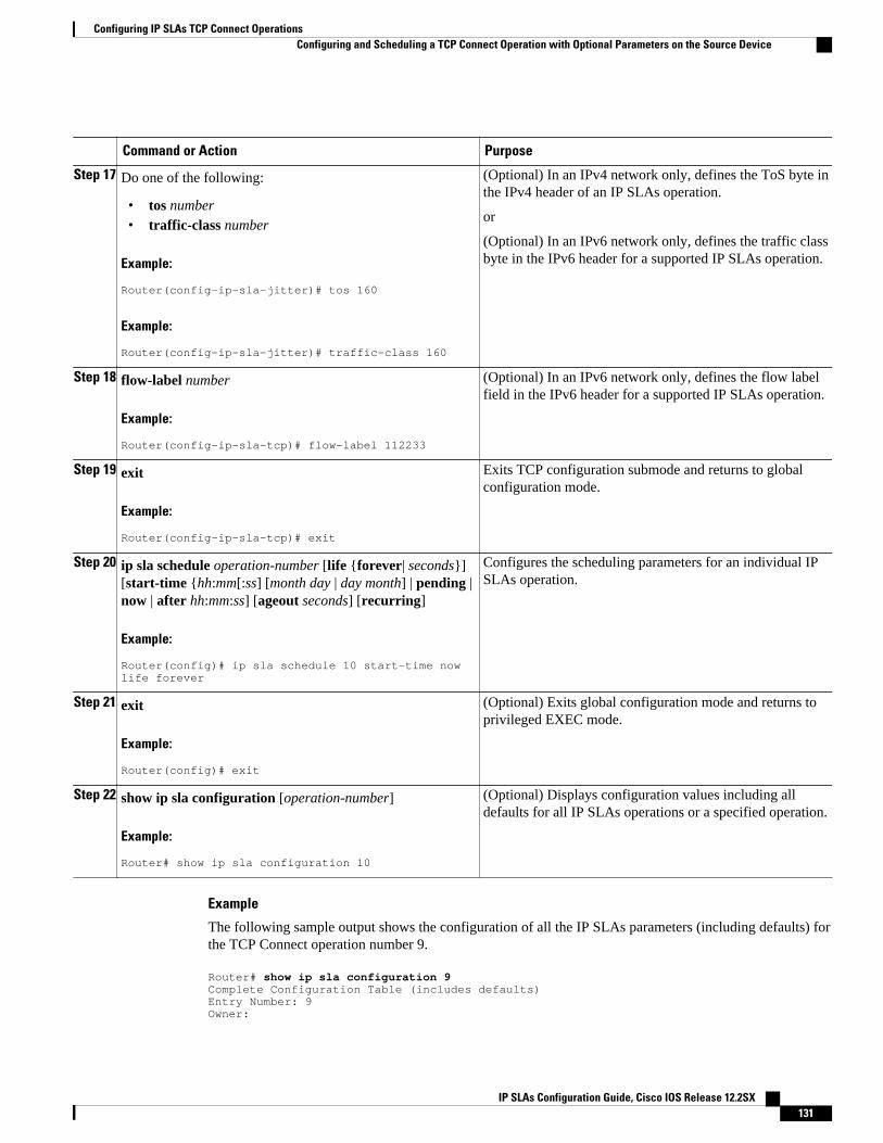
Command or Action Purpose
Step 17 Do one of the following:
• tos number• traffic-class number
Example:
Router(config-ip-sla-jitter)# tos 160
Example:
Router(config-ip-sla-jitter)# traffic-class 160
(Optional) In an IPv4 network only, defines the ToS byte inthe IPv4 header of an IP SLAs operation.
or
(Optional) In an IPv6 network only, defines the traffic classbyte in the IPv6 header for a supported IP SLAs operation.
Step 18 flow-label number
Example:
Router(config-ip-sla-tcp)# flow-label 112233
(Optional) In an IPv6 network only, defines the flow labelfield in the IPv6 header for a supported IP SLAs operation.
Step 19 exit
Example:
Router(config-ip-sla-tcp)# exit
Exits TCP configuration submode and returns to globalconfiguration mode.
Step 20 ip sla schedule operation-number [life {forever| seconds}][start-time {hh:mm[:ss] [month day | day month] | pending |now | after hh:mm:ss] [ageout seconds] [recurring]
Example:
Router(config)# ip sla schedule 10 start-time now life forever
Configures the scheduling parameters for an individual IPSLAs operation.
Step 21 exit
Example:
Router(config)# exit
(Optional) Exits global configuration mode and returns toprivileged EXEC mode.
Step 22 show ip sla configuration [operation-number]
Example:
Router# show ip sla configuration 10
(Optional) Displays configuration values including alldefaults for all IP SLAs operations or a specified operation.
Example
The following sample output shows the configuration of all the IP SLAs parameters (including defaults) forthe TCP Connect operation number 9.
Router# show ip sla configuration 9Complete Configuration Table (includes defaults)Entry Number: 9Owner:
Configuring IP SLAs TCP Connect OperationsConfiguring and Scheduling a TCP Connect Operation with Optional Parameters on the Source Device
IP SLAs Configuration Guide, Cisco IOS Release 12.2SX 131
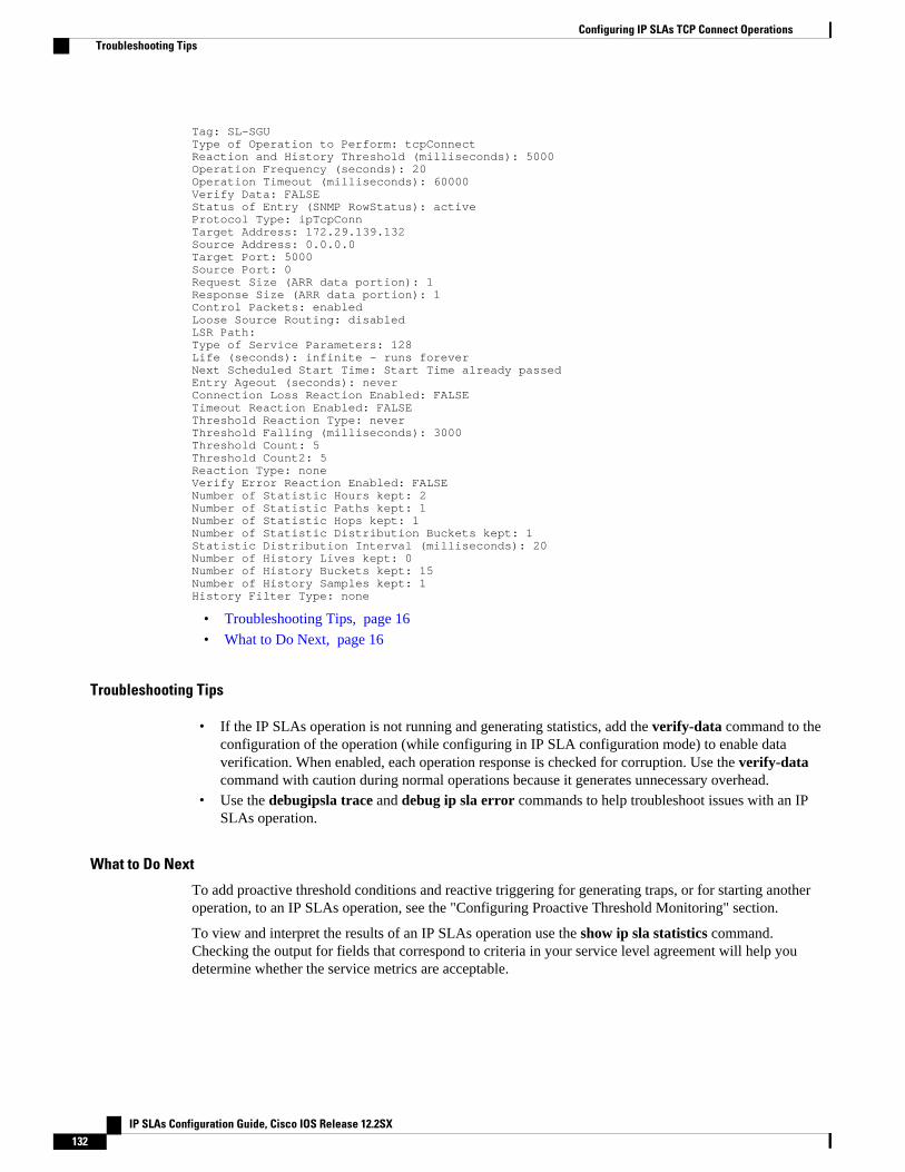
Tag: SL-SGU Type of Operation to Perform: tcpConnectReaction and History Threshold (milliseconds): 5000Operation Frequency (seconds): 20Operation Timeout (milliseconds): 60000Verify Data: FALSEStatus of Entry (SNMP RowStatus): activeProtocol Type: ipTcpConnTarget Address: 172.29.139.132Source Address: 0.0.0.0Target Port: 5000Source Port: 0Request Size (ARR data portion): 1Response Size (ARR data portion): 1Control Packets: enabledLoose Source Routing: disabledLSR Path: Type of Service Parameters: 128Life (seconds): infinite - runs foreverNext Scheduled Start Time: Start Time already passedEntry Ageout (seconds): neverConnection Loss Reaction Enabled: FALSETimeout Reaction Enabled: FALSEThreshold Reaction Type: neverThreshold Falling (milliseconds): 3000Threshold Count: 5Threshold Count2: 5Reaction Type: noneVerify Error Reaction Enabled: FALSENumber of Statistic Hours kept: 2Number of Statistic Paths kept: 1Number of Statistic Hops kept: 1Number of Statistic Distribution Buckets kept: 1Statistic Distribution Interval (milliseconds): 20Number of History Lives kept: 0Number of History Buckets kept: 15Number of History Samples kept: 1History Filter Type: none
• Troubleshooting Tips, page 16
• What to Do Next, page 16
Troubleshooting Tips
• If the IP SLAs operation is not running and generating statistics, add the verify-data command to theconfiguration of the operation (while configuring in IP SLA configuration mode) to enable dataverification. When enabled, each operation response is checked for corruption. Use the verify-datacommand with caution during normal operations because it generates unnecessary overhead.
• Use the debugipsla trace and debug ip sla error commands to help troubleshoot issues with an IPSLAs operation.
What to Do Next
To add proactive threshold conditions and reactive triggering for generating traps, or for starting anotheroperation, to an IP SLAs operation, see the "Configuring Proactive Threshold Monitoring" section.
To view and interpret the results of an IP SLAs operation use the show ip sla statistics command.Checking the output for fields that correspond to criteria in your service level agreement will help youdetermine whether the service metrics are acceptable.
Configuring IP SLAs TCP Connect Operations Troubleshooting Tips
IP SLAs Configuration Guide, Cisco IOS Release 12.2SX132
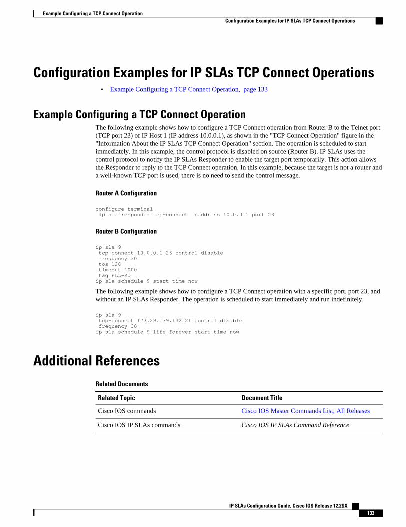
Configuration Examples for IP SLAs TCP Connect Operations• Example Configuring a TCP Connect Operation, page 133
Example Configuring a TCP Connect OperationThe following example shows how to configure a TCP Connect operation from Router B to the Telnet port(TCP port 23) of IP Host 1 (IP address 10.0.0.1), as shown in the "TCP Connect Operation" figure in the"Information About the IP SLAs TCP Connect Operation" section. The operation is scheduled to startimmediately. In this example, the control protocol is disabled on source (Router B). IP SLAs uses thecontrol protocol to notify the IP SLAs Responder to enable the target port temporarily. This action allowsthe Responder to reply to the TCP Connect operation. In this example, because the target is not a router anda well-known TCP port is used, there is no need to send the control message.
Router A Configuration
configure terminal ip sla responder tcp-connect ipaddress 10.0.0.1 port 23
Router B Configuration
ip sla 9 tcp-connect 10.0.0.1 23 control disable frequency 30 tos 128 timeout 1000 tag FLL-ROip sla schedule 9 start-time now
The following example shows how to configure a TCP Connect operation with a specific port, port 23, andwithout an IP SLAs Responder. The operation is scheduled to start immediately and run indefinitely.
ip sla 9 tcp-connect 173.29.139.132 21 control disable frequency 30ip sla schedule 9 life forever start-time now
Additional ReferencesRelated Documents
Related Topic Document Title
Cisco IOS commands Cisco IOS Master Commands List, All Releases
Cisco IOS IP SLAs commands Cisco IOS IP SLAs Command Reference
Example Configuring a TCP Connect OperationConfiguration Examples for IP SLAs TCP Connect Operations
IP SLAs Configuration Guide, Cisco IOS Release 12.2SX 133
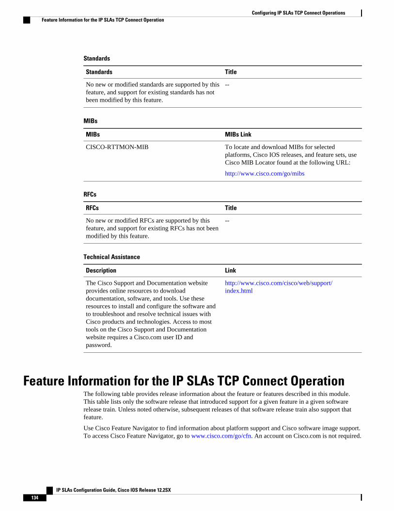
Standards
Standards Title
No new or modified standards are supported by thisfeature, and support for existing standards has notbeen modified by this feature.
--
MIBs
MIBs MIBs Link
CISCO-RTTMON-MIB To locate and download MIBs for selectedplatforms, Cisco IOS releases, and feature sets, useCisco MIB Locator found at the following URL:
http://www.cisco.com/go/mibs
RFCs
RFCs Title
No new or modified RFCs are supported by thisfeature, and support for existing RFCs has not beenmodified by this feature.
--
Technical Assistance
Description Link
The Cisco Support and Documentation websiteprovides online resources to downloaddocumentation, software, and tools. Use theseresources to install and configure the software andto troubleshoot and resolve technical issues withCisco products and technologies. Access to mosttools on the Cisco Support and Documentationwebsite requires a Cisco.com user ID andpassword.
http://www.cisco.com/cisco/web/support/index.html
Feature Information for the IP SLAs TCP Connect OperationThe following table provides release information about the feature or features described in this module.This table lists only the software release that introduced support for a given feature in a given softwarerelease train. Unless noted otherwise, subsequent releases of that software release train also support thatfeature.
Use Cisco Feature Navigator to find information about platform support and Cisco software image support.To access Cisco Feature Navigator, go to www.cisco.com/go/cfn. An account on Cisco.com is not required.
Configuring IP SLAs TCP Connect Operations Feature Information for the IP SLAs TCP Connect Operation
IP SLAs Configuration Guide, Cisco IOS Release 12.2SX134
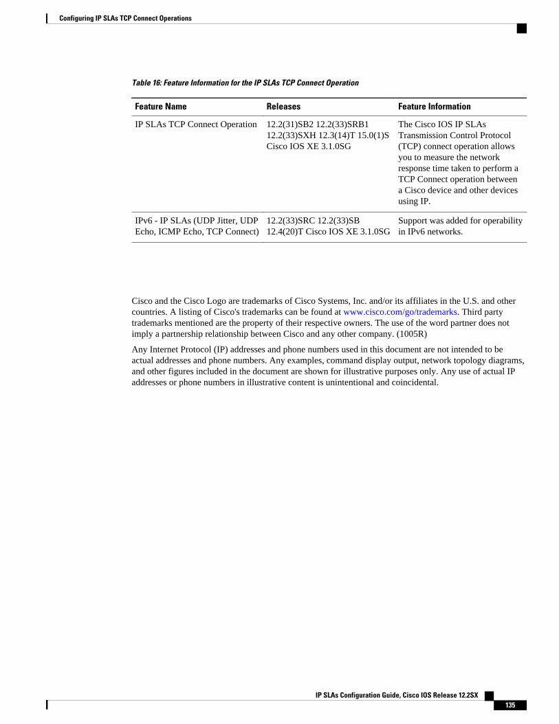
Table 16: Feature Information for the IP SLAs TCP Connect Operation
Feature Name Releases Feature Information
IP SLAs TCP Connect Operation 12.2(31)SB2 12.2(33)SRB112.2(33)SXH 12.3(14)T 15.0(1)SCisco IOS XE 3.1.0SG
The Cisco IOS IP SLAsTransmission Control Protocol(TCP) connect operation allowsyou to measure the networkresponse time taken to perform aTCP Connect operation betweena Cisco device and other devicesusing IP.
IPv6 - IP SLAs (UDP Jitter, UDPEcho, ICMP Echo, TCP Connect)
12.2(33)SRC 12.2(33)SB12.4(20)T Cisco IOS XE 3.1.0SG
Support was added for operabilityin IPv6 networks.
Cisco and the Cisco Logo are trademarks of Cisco Systems, Inc. and/or its affiliates in the U.S. and othercountries. A listing of Cisco's trademarks can be found at www.cisco.com/go/trademarks. Third partytrademarks mentioned are the property of their respective owners. The use of the word partner does notimply a partnership relationship between Cisco and any other company. (1005R)
Any Internet Protocol (IP) addresses and phone numbers used in this document are not intended to beactual addresses and phone numbers. Any examples, command display output, network topology diagrams,and other figures included in the document are shown for illustrative purposes only. Any use of actual IPaddresses or phone numbers in illustrative content is unintentional and coincidental.
Configuring IP SLAs TCP Connect Operations
IP SLAs Configuration Guide, Cisco IOS Release 12.2SX 135

Example Configuring a TCP Connect Operation
IP SLAs Configuration Guide, Cisco IOS Release 12.2SX136
Configuring IP SLAs ICMP Echo Operations
This module describes how to configure an IP Service Level Agreements (SLAs) Internet ControlMessage Protocol (ICMP) Echo operation to monitor end-to-end response time between a Cisco routerand devices using IPv4 or IPv6. ICMP Echo is useful for troubleshooting network connectivity issues.This module also demonstrates how the results of the ICMP Echo operation can be displayed andanalyzed to determine how the network IP connections are performing.
• Finding Feature Information, page 137• Restrictions for IP SLAs ICMP Echo Operations, page 137• Information About IP SLAs ICMP Echo Operations, page 137• How to Configure IP SLAs ICMP Echo Operations, page 138• Configuration Examples for IP SLAs ICMP Echo Operations, page 145• Additional References, page 146• Feature Information for IP SLAs ICMP Echo Operations, page 147
Finding Feature InformationYour software release may not support all the features documented in this module. For the latest featureinformation and caveats, see the release notes for your platform and software release. To find informationabout the features documented in this module, and to see a list of the releases in which each feature issupported, see the Feature Information Table at the end of this document.
Use Cisco Feature Navigator to find information about platform support and Cisco software image support.To access Cisco Feature Navigator, go to www.cisco.com/go/cfn. An account on Cisco.com is not required.
Restrictions for IP SLAs ICMP Echo OperationsWe recommend using a Cisco networking device as the destination device although any networking devicethat supports RFC 862, Echo protocol, can be used.
Information About IP SLAs ICMP Echo Operations• ICMP Echo Operation, page 138
IP SLAs Configuration Guide, Cisco IOS Release 12.2SX 137
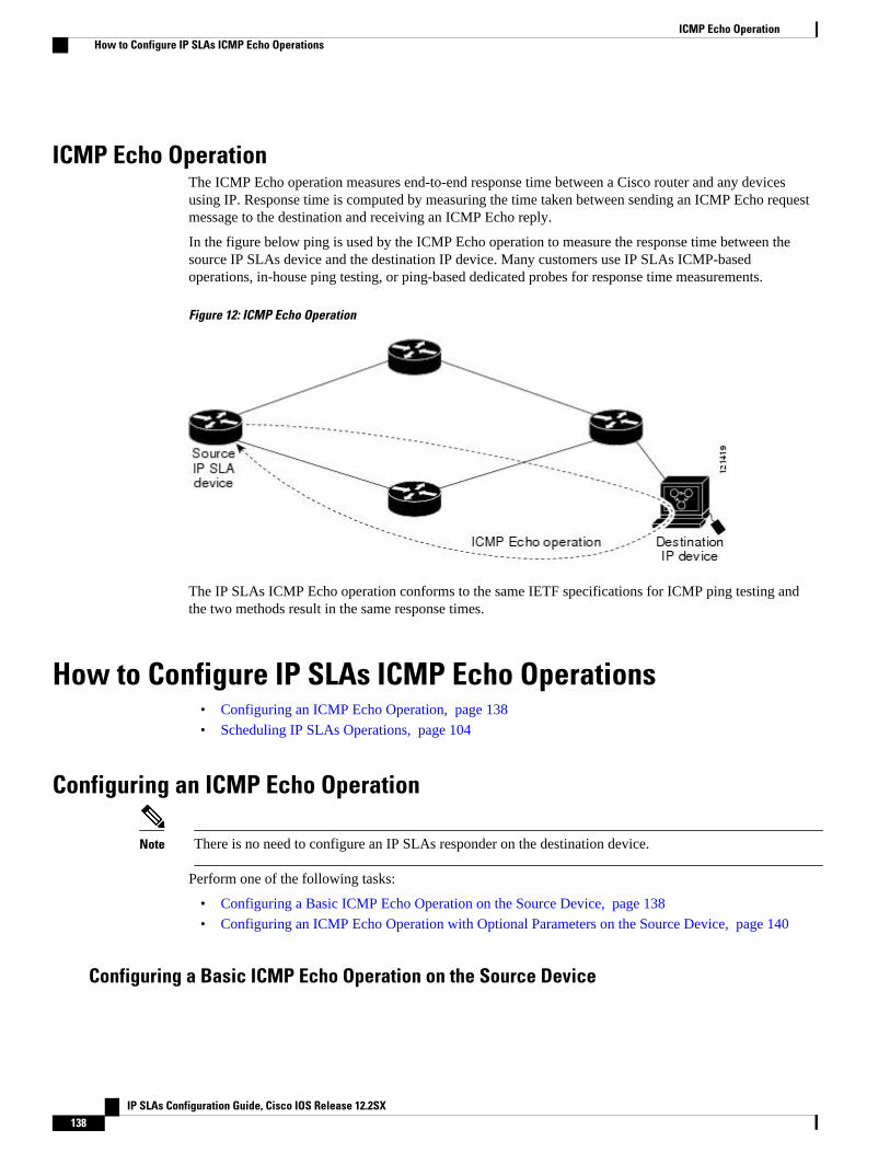
ICMP Echo OperationThe ICMP Echo operation measures end-to-end response time between a Cisco router and any devicesusing IP. Response time is computed by measuring the time taken between sending an ICMP Echo requestmessage to the destination and receiving an ICMP Echo reply.
In the figure below ping is used by the ICMP Echo operation to measure the response time between thesource IP SLAs device and the destination IP device. Many customers use IP SLAs ICMP-basedoperations, in-house ping testing, or ping-based dedicated probes for response time measurements.
Figure 12: ICMP Echo Operation
The IP SLAs ICMP Echo operation conforms to the same IETF specifications for ICMP ping testing andthe two methods result in the same response times.
How to Configure IP SLAs ICMP Echo Operations• Configuring an ICMP Echo Operation, page 138
• Scheduling IP SLAs Operations, page 104
Configuring an ICMP Echo Operation
Note There is no need to configure an IP SLAs responder on the destination device.
Perform one of the following tasks:
• Configuring a Basic ICMP Echo Operation on the Source Device, page 138
• Configuring an ICMP Echo Operation with Optional Parameters on the Source Device, page 140
Configuring a Basic ICMP Echo Operation on the Source Device
ICMP Echo Operation How to Configure IP SLAs ICMP Echo Operations
IP SLAs Configuration Guide, Cisco IOS Release 12.2SX138
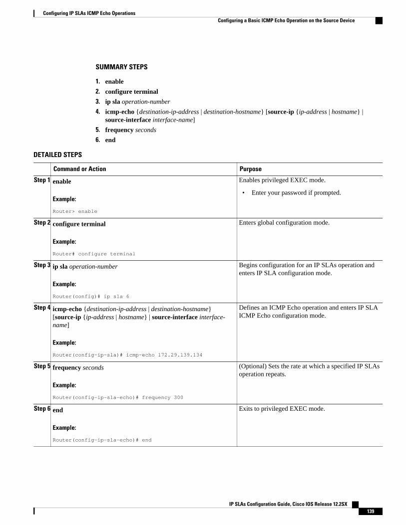
SUMMARY STEPS
1. enable
2. configure terminal
3. ip sla operation-number
4. icmp-echo {destination-ip-address | destination-hostname} [source-ip {ip-address | hostname} |source-interface interface-name]
5. frequency seconds
6. end
DETAILED STEPS
Command or Action Purpose
Step 1 enable
Example:
Router> enable
Enables privileged EXEC mode.
• Enter your password if prompted.
Step 2 configure terminal
Example:
Router# configure terminal
Enters global configuration mode.
Step 3 ip sla operation-number
Example:
Router(config)# ip sla 6
Begins configuration for an IP SLAs operation andenters IP SLA configuration mode.
Step 4 icmp-echo {destination-ip-address | destination-hostname}[source-ip {ip-address | hostname} | source-interface interface-name]
Example:
Router(config-ip-sla)# icmp-echo 172.29.139.134
Defines an ICMP Echo operation and enters IP SLAICMP Echo configuration mode.
Step 5 frequency seconds
Example:
Router(config-ip-sla-echo)# frequency 300
(Optional) Sets the rate at which a specified IP SLAsoperation repeats.
Step 6 end
Example:
Router(config-ip-sla-echo)# end
Exits to privileged EXEC mode.
Configuring IP SLAs ICMP Echo OperationsConfiguring a Basic ICMP Echo Operation on the Source Device
IP SLAs Configuration Guide, Cisco IOS Release 12.2SX 139
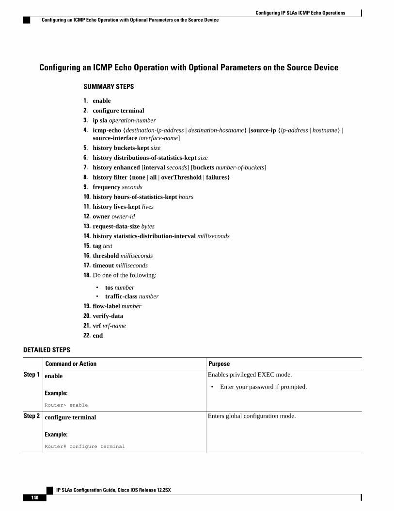
Configuring an ICMP Echo Operation with Optional Parameters on the Source Device
SUMMARY STEPS
1. enable
2. configure terminal
3. ip sla operation-number
4. icmp-echo {destination-ip-address | destination-hostname} [source-ip {ip-address | hostname} |source-interface interface-name]
5. history buckets-kept size
6. history distributions-of-statistics-kept size
7. history enhanced [interval seconds] [buckets number-of-buckets]
8. history filter {none | all | overThreshold | failures}
9. frequency seconds
10. history hours-of-statistics-kept hours
11. history lives-kept lives
12. owner owner-id
13. request-data-size bytes
14. history statistics-distribution-interval milliseconds
15. tag text
16. threshold milliseconds
17. timeout milliseconds
18. Do one of the following:
• tos number• traffic-class number
19. flow-label number
20. verify-data
21. vrf vrf-name
22. end
DETAILED STEPS
Command or Action Purpose
Step 1 enable
Example:
Router> enable
Enables privileged EXEC mode.
• Enter your password if prompted.
Step 2 configure terminal
Example:
Router# configure terminal
Enters global configuration mode.
Configuring IP SLAs ICMP Echo Operations Configuring an ICMP Echo Operation with Optional Parameters on the Source Device
IP SLAs Configuration Guide, Cisco IOS Release 12.2SX140
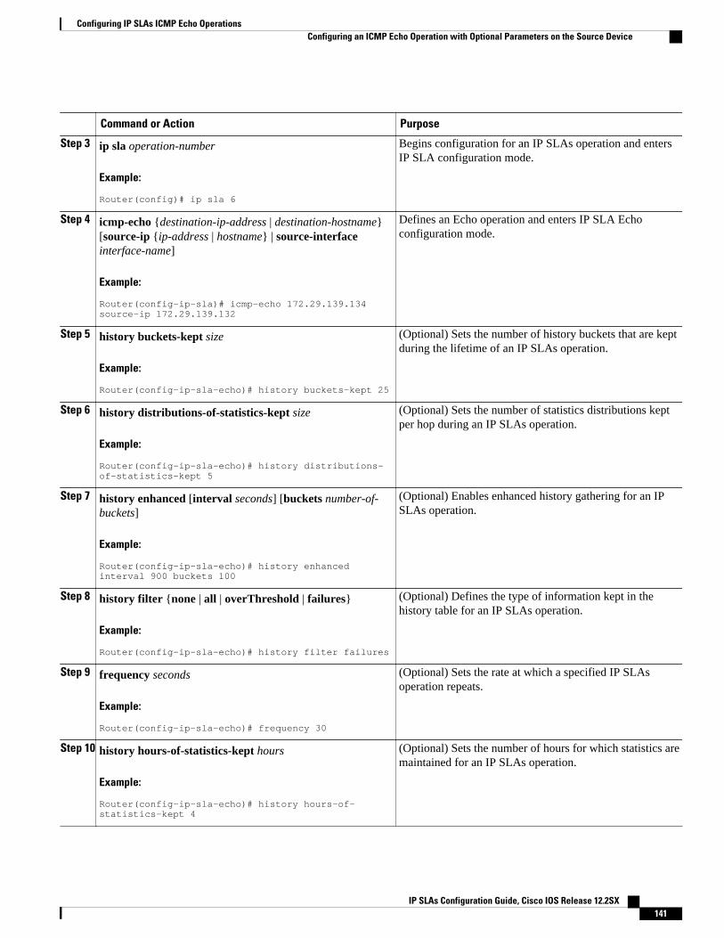
Command or Action Purpose
Step 3 ip sla operation-number
Example:
Router(config)# ip sla 6
Begins configuration for an IP SLAs operation and entersIP SLA configuration mode.
Step 4 icmp-echo {destination-ip-address | destination-hostname}[source-ip {ip-address | hostname} | source-interfaceinterface-name]
Example:
Router(config-ip-sla)# icmp-echo 172.29.139.134 source-ip 172.29.139.132
Defines an Echo operation and enters IP SLA Echoconfiguration mode.
Step 5 history buckets-kept size
Example:
Router(config-ip-sla-echo)# history buckets-kept 25
(Optional) Sets the number of history buckets that are keptduring the lifetime of an IP SLAs operation.
Step 6 history distributions-of-statistics-kept size
Example:
Router(config-ip-sla-echo)# history distributions-of-statistics-kept 5
(Optional) Sets the number of statistics distributions keptper hop during an IP SLAs operation.
Step 7 history enhanced [interval seconds] [buckets number-of-buckets]
Example:
Router(config-ip-sla-echo)# history enhanced interval 900 buckets 100
(Optional) Enables enhanced history gathering for an IPSLAs operation.
Step 8 history filter {none | all | overThreshold | failures}
Example:
Router(config-ip-sla-echo)# history filter failures
(Optional) Defines the type of information kept in thehistory table for an IP SLAs operation.
Step 9 frequency seconds
Example:
Router(config-ip-sla-echo)# frequency 30
(Optional) Sets the rate at which a specified IP SLAsoperation repeats.
Step 10 history hours-of-statistics-kept hours
Example:
Router(config-ip-sla-echo)# history hours-of-statistics-kept 4
(Optional) Sets the number of hours for which statistics aremaintained for an IP SLAs operation.
Configuring IP SLAs ICMP Echo OperationsConfiguring an ICMP Echo Operation with Optional Parameters on the Source Device
IP SLAs Configuration Guide, Cisco IOS Release 12.2SX 141
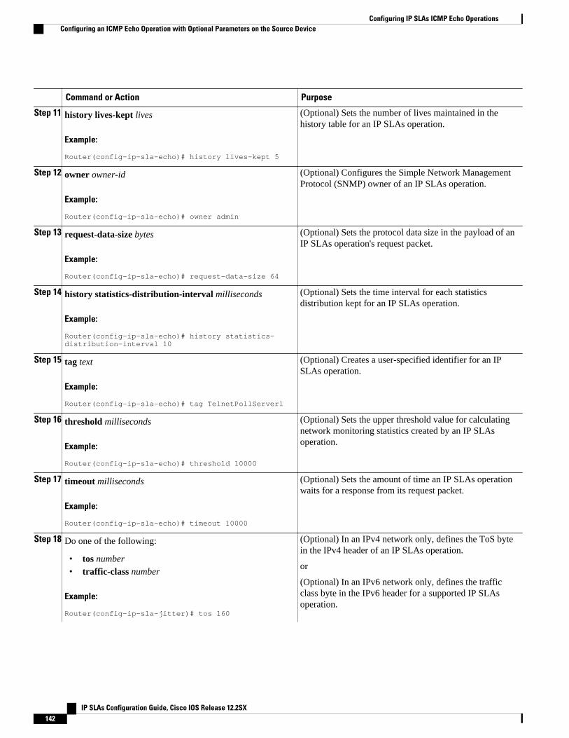
Command or Action Purpose
Step 11 history lives-kept lives
Example:
Router(config-ip-sla-echo)# history lives-kept 5
(Optional) Sets the number of lives maintained in thehistory table for an IP SLAs operation.
Step 12 owner owner-id
Example:
Router(config-ip-sla-echo)# owner admin
(Optional) Configures the Simple Network ManagementProtocol (SNMP) owner of an IP SLAs operation.
Step 13 request-data-size bytes
Example:
Router(config-ip-sla-echo)# request-data-size 64
(Optional) Sets the protocol data size in the payload of anIP SLAs operation's request packet.
Step 14 history statistics-distribution-interval milliseconds
Example:
Router(config-ip-sla-echo)# history statistics-distribution-interval 10
(Optional) Sets the time interval for each statisticsdistribution kept for an IP SLAs operation.
Step 15 tag text
Example:
Router(config-ip-sla-echo)# tag TelnetPollServer1
(Optional) Creates a user-specified identifier for an IPSLAs operation.
Step 16 threshold milliseconds
Example:
Router(config-ip-sla-echo)# threshold 10000
(Optional) Sets the upper threshold value for calculatingnetwork monitoring statistics created by an IP SLAsoperation.
Step 17 timeout milliseconds
Example:
Router(config-ip-sla-echo)# timeout 10000
(Optional) Sets the amount of time an IP SLAs operationwaits for a response from its request packet.
Step 18 Do one of the following:
• tos number• traffic-class number
Example:
Router(config-ip-sla-jitter)# tos 160
(Optional) In an IPv4 network only, defines the ToS bytein the IPv4 header of an IP SLAs operation.
or
(Optional) In an IPv6 network only, defines the trafficclass byte in the IPv6 header for a supported IP SLAsoperation.
Configuring IP SLAs ICMP Echo Operations Configuring an ICMP Echo Operation with Optional Parameters on the Source Device
IP SLAs Configuration Guide, Cisco IOS Release 12.2SX142
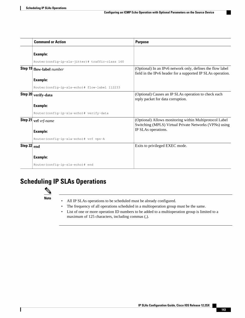
Command or Action Purpose
Example:
Router(config-ip-sla-jitter)# traffic-class 160
Step 19 flow-label number
Example:
Router(config-ip-sla-echo)# flow-label 112233
(Optional) In an IPv6 network only, defines the flow labelfield in the IPv6 header for a supported IP SLAs operation.
Step 20 verify-data
Example:
Router(config-ip-sla-echo)# verify-data
(Optional) Causes an IP SLAs operation to check eachreply packet for data corruption.
Step 21 vrf vrf-name
Example:
Router(config-ip-sla-echo)# vrf vpn-A
(Optional) Allows monitoring within Multiprotocol LabelSwitching (MPLS) Virtual Private Networks (VPNs) usingIP SLAs operations.
Step 22 end
Example:
Router(config-ip-sla-echo)# end
Exits to privileged EXEC mode.
Scheduling IP SLAs Operations
Note• All IP SLAs operations to be scheduled must be already configured.• The frequency of all operations scheduled in a multioperation group must be the same.• List of one or more operation ID numbers to be added to a multioperation group is limited to a
maximum of 125 characters, including commas (,).
Scheduling IP SLAs OperationsConfiguring an ICMP Echo Operation with Optional Parameters on the Source Device
IP SLAs Configuration Guide, Cisco IOS Release 12.2SX 143

SUMMARY STEPS
1. enable
2. configure terminal
3. Do one of the following:
• ip sla schedule operation-number [life {forever | seconds}] [start-time {hh : mm[: ss] [month day| day month] | pending | now | after hh : mm : ss}] [ageout seconds] [recurring]
• ip sla group schedule group-operation-number operation-id-numbers schedule-period schedule-period-range [ageout seconds] [frequency group-operation-frequency] [life{forever | seconds}][start-time{hh:mm[:ss] [month day | day month] | pending | now | after hh:mm:ss}]
4. exit
5. show ip sla group schedule
6. show ip sla configuration
DETAILED STEPS
Command or Action Purpose
Step 1 enable
Example:
Router> enable
Enables privileged EXEC mode.
• Enter your password if prompted.
Step 2 configure terminal
Example:
Router# configure terminal
Enters global configuration mode.
Step 3 Do one of the following:
• ip sla schedule operation-number [life {forever | seconds}] [start-time{hh : mm[: ss] [month day | day month] | pending | now | after hh : mm: ss}] [ageout seconds] [recurring]
• ip sla group schedule group-operation-number operation-id-numbersschedule-period schedule-period-range [ageout seconds] [frequencygroup-operation-frequency] [life{forever | seconds}] [start-time{hh:mm[:ss] [month day | day month] | pending | now | afterhh:mm:ss}]
Example:
Router(config)# ip sla schedule 10 start-time now life forever
Example:
Router(config)# ip sla group schedule 1 3,4,6-9
For individual IP SLAs operations only:
Configures the scheduling parameters for anindividual IP SLAs operation.
or
For multioperation scheduler only:
Specifies an IP SLAs operation groupnumber and the range of operation numbersto be scheduled in global configurationmode.
Step 4 exit Exits to privileged EXEC mode.
Configuring IP SLAs ICMP Echo Operations Configuring an ICMP Echo Operation with Optional Parameters on the Source Device
IP SLAs Configuration Guide, Cisco IOS Release 12.2SX144
Command or Action Purpose
Example:
Router(config)# exit
Step 5 show ip sla group schedule
Example:
Router# show ip sla group schedule
(Optional) Displays the IP SLAs groupschedule details.
Step 6 show ip sla configuration
Example:
Router# show ip sla configuration
(Optional) Displays the IP SLAsconfiguration details.
• Troubleshooting Tips, page 16• What to Do Next, page 16
Troubleshooting Tips
• If the IP SLAs operation is not running and generating statistics, add the verify-data command to theconfiguration of the operation (while configuring in IP SLA configuration mode) to enable dataverification. When enabled, each operation response is checked for corruption. Use the verify-datacommand with caution during normal operations because it generates unnecessary overhead.
• Use the debugipsla trace and debug ip sla error commands to help troubleshoot issues with an IPSLAs operation.
What to Do NextTo add proactive threshold conditions and reactive triggering for generating traps, or for starting anotheroperation, to an IP SLAs operation, see the "Configuring Proactive Threshold Monitoring" section.
To view and interpret the results of an IP SLAs operation use the show ip sla statistics command.Checking the output for fields that correspond to criteria in your service level agreement will help youdetermine whether the service metrics are acceptable.
Configuration Examples for IP SLAs ICMP Echo Operations• Example Configuring an ICMP Echo Operation, page 145
Example Configuring an ICMP Echo OperationThe following example shows how to configure an IP SLAs operation type of ICMP Echo that will startimmediately and run indefinitely.
ip sla 6
Example Configuring an ICMP Echo OperationTroubleshooting Tips
IP SLAs Configuration Guide, Cisco IOS Release 12.2SX 145
icmp-echo 172.29.139.134 source-ip 172.29.139.132 frequency 300 request-data-size 28 tos 160 timeout 2000 tag SFO-ROip sla schedule 6 life forever start-time now
Additional ReferencesRelated Documents
Related Topic Document Title
Cisco IOS commands Cisco IOS Master Commands List, All Releases
Cisco IOS IP SLAs commands Cisco IOS IP SLAs Command Reference
Cisco IOS IP SLAs: general information “Cisco IOS IP SLAs Overview” chapter of theCisco IOS IP SLAs Configuration Guide
Standards
Standards Title
No new or modified standards are supported by thisfeature, and support for existing standards has notbeen modified by this feature.
--
MIBs
MIBs MIBs Link
CISCO-RTTMON-MIB To locate and download MIBs for selectedplatforms, Cisco IOS releases, and feature sets, useCisco MIB Locator found at the following URL:
http://www.cisco.com/go/mibs
RFCs
RFCs Title
RFC 862 Echo Protocol
Technical Assistance
Description Link
The Cisco Support and Documentation websiteprovides online resources to downloaddocumentation, software, and tools. Use these
http://www.cisco.com/cisco/web/support/index.html
Configuring IP SLAs ICMP Echo Operations Additional References
IP SLAs Configuration Guide, Cisco IOS Release 12.2SX146
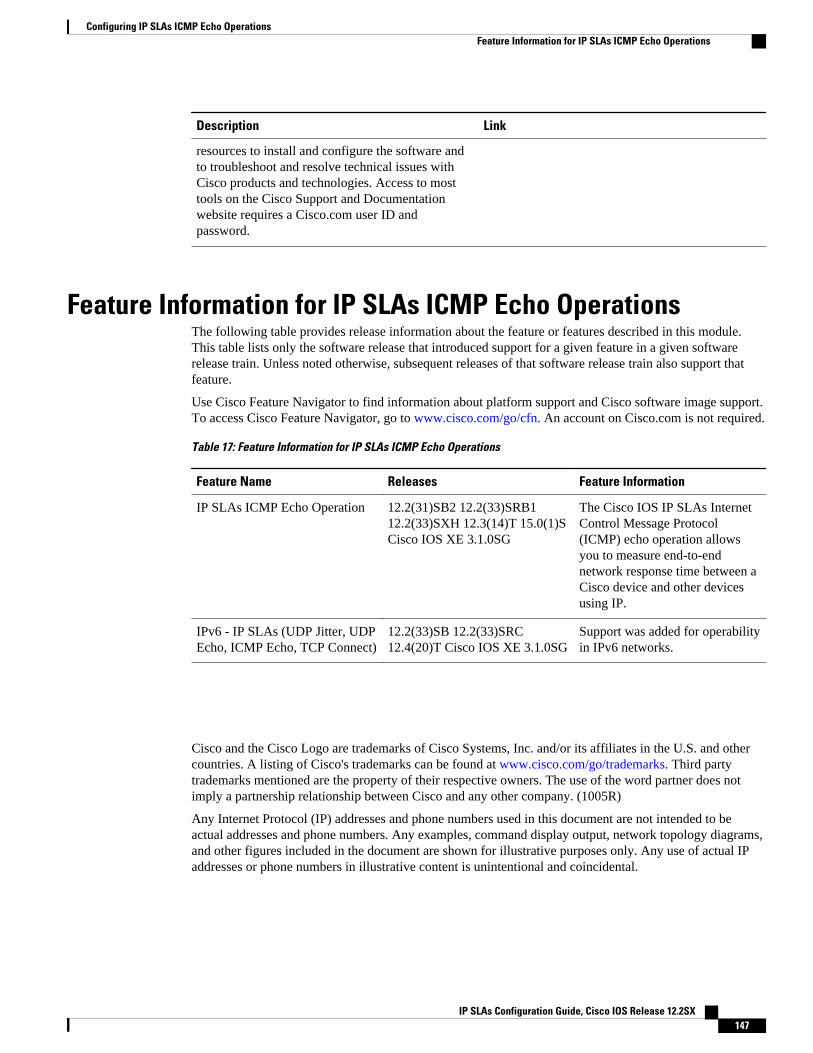
Description Link
resources to install and configure the software andto troubleshoot and resolve technical issues withCisco products and technologies. Access to mosttools on the Cisco Support and Documentationwebsite requires a Cisco.com user ID andpassword.
Feature Information for IP SLAs ICMP Echo OperationsThe following table provides release information about the feature or features described in this module.This table lists only the software release that introduced support for a given feature in a given softwarerelease train. Unless noted otherwise, subsequent releases of that software release train also support thatfeature.
Use Cisco Feature Navigator to find information about platform support and Cisco software image support.To access Cisco Feature Navigator, go to www.cisco.com/go/cfn. An account on Cisco.com is not required.
Table 17: Feature Information for IP SLAs ICMP Echo Operations
Feature Name Releases Feature Information
IP SLAs ICMP Echo Operation 12.2(31)SB2 12.2(33)SRB112.2(33)SXH 12.3(14)T 15.0(1)SCisco IOS XE 3.1.0SG
The Cisco IOS IP SLAs InternetControl Message Protocol(ICMP) echo operation allowsyou to measure end-to-endnetwork response time between aCisco device and other devicesusing IP.
IPv6 - IP SLAs (UDP Jitter, UDPEcho, ICMP Echo, TCP Connect)
12.2(33)SB 12.2(33)SRC12.4(20)T Cisco IOS XE 3.1.0SG
Support was added for operabilityin IPv6 networks.
Cisco and the Cisco Logo are trademarks of Cisco Systems, Inc. and/or its affiliates in the U.S. and othercountries. A listing of Cisco's trademarks can be found at www.cisco.com/go/trademarks. Third partytrademarks mentioned are the property of their respective owners. The use of the word partner does notimply a partnership relationship between Cisco and any other company. (1005R)
Any Internet Protocol (IP) addresses and phone numbers used in this document are not intended to beactual addresses and phone numbers. Any examples, command display output, network topology diagrams,and other figures included in the document are shown for illustrative purposes only. Any use of actual IPaddresses or phone numbers in illustrative content is unintentional and coincidental.
Configuring IP SLAs ICMP Echo OperationsFeature Information for IP SLAs ICMP Echo Operations
IP SLAs Configuration Guide, Cisco IOS Release 12.2SX 147

Example Configuring an ICMP Echo Operation
IP SLAs Configuration Guide, Cisco IOS Release 12.2SX148
Configuring IP SLAs ICMP Path EchoOperations
This module describes how to configure an IP Service Level Agreements (SLAs) Internet ControlMessage Protocol (ICMP) Path Echo operation to monitor end-to-end and hop-by-hop response timebetween a Cisco router and devices using IP. ICMP Path Echo is useful for determining networkavailability and for troubleshooting network connectivity issues. The results of the ICMP Path Echooperation can be displayed and analyzed to determine how ICMP is performing.
• Finding Feature Information, page 149• Restrictions for IP SLAs ICMP Path Echo Operations, page 149• Information About IP SLAs ICMP Path Echo Operations, page 149• How to Configure IP SLAs ICMP Path Echo Operations, page 150• Configuration Examples for IP SLAs ICMP Path Echo Operations, page 157• Additional References, page 158• Feature Information for IP SLAs ICMP Path Echo Operations, page 159
Finding Feature InformationYour software release may not support all the features documented in this module. For the latest featureinformation and caveats, see the release notes for your platform and software release. To find informationabout the features documented in this module, and to see a list of the releases in which each feature issupported, see the Feature Information Table at the end of this document.
Use Cisco Feature Navigator to find information about platform support and Cisco software image support.To access Cisco Feature Navigator, go to www.cisco.com/go/cfn. An account on Cisco.com is not required.
Restrictions for IP SLAs ICMP Path Echo OperationsWe recommend using a Cisco networking device as the destination device although any networking devicethat supports RFC 862, Echo protocol, can be used.
Information About IP SLAs ICMP Path Echo Operations• ICMP Path Echo Operation, page 150
IP SLAs Configuration Guide, Cisco IOS Release 12.2SX 149
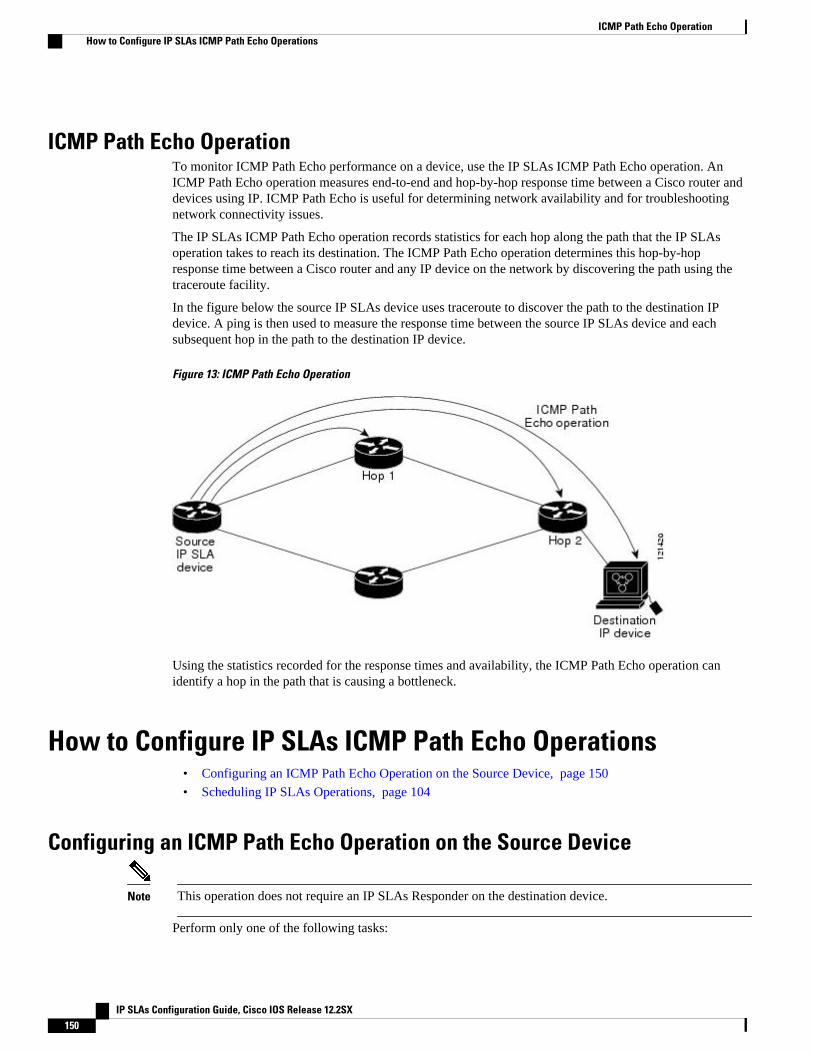
ICMP Path Echo OperationTo monitor ICMP Path Echo performance on a device, use the IP SLAs ICMP Path Echo operation. AnICMP Path Echo operation measures end-to-end and hop-by-hop response time between a Cisco router anddevices using IP. ICMP Path Echo is useful for determining network availability and for troubleshootingnetwork connectivity issues.
The IP SLAs ICMP Path Echo operation records statistics for each hop along the path that the IP SLAsoperation takes to reach its destination. The ICMP Path Echo operation determines this hop-by-hopresponse time between a Cisco router and any IP device on the network by discovering the path using thetraceroute facility.
In the figure below the source IP SLAs device uses traceroute to discover the path to the destination IPdevice. A ping is then used to measure the response time between the source IP SLAs device and eachsubsequent hop in the path to the destination IP device.
Figure 13: ICMP Path Echo Operation
Using the statistics recorded for the response times and availability, the ICMP Path Echo operation canidentify a hop in the path that is causing a bottleneck.
How to Configure IP SLAs ICMP Path Echo Operations• Configuring an ICMP Path Echo Operation on the Source Device, page 150
• Scheduling IP SLAs Operations, page 104
Configuring an ICMP Path Echo Operation on the Source Device
Note This operation does not require an IP SLAs Responder on the destination device.
Perform only one of the following tasks:
ICMP Path Echo Operation How to Configure IP SLAs ICMP Path Echo Operations
IP SLAs Configuration Guide, Cisco IOS Release 12.2SX150
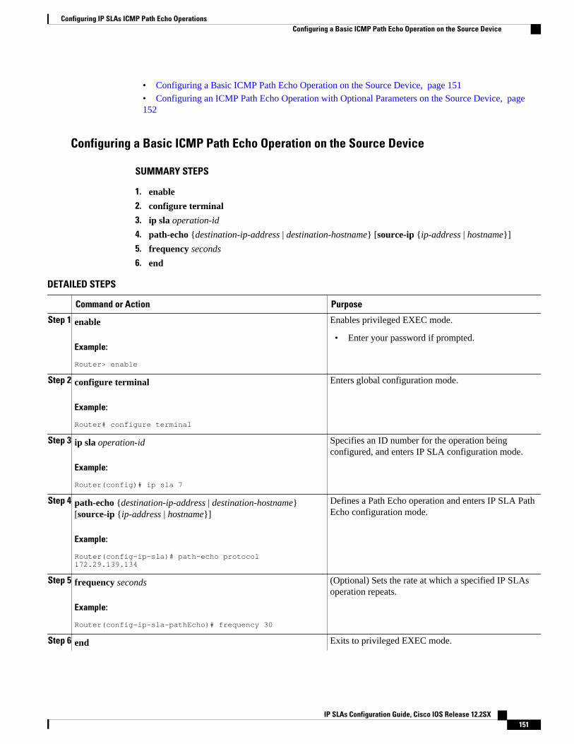
• Configuring a Basic ICMP Path Echo Operation on the Source Device, page 151
• Configuring an ICMP Path Echo Operation with Optional Parameters on the Source Device, page152
Configuring a Basic ICMP Path Echo Operation on the Source Device
SUMMARY STEPS
1. enable
2. configure terminal
3. ip sla operation-id
4. path-echo {destination-ip-address | destination-hostname} [source-ip {ip-address | hostname}]
5. frequency seconds
6. end
DETAILED STEPS
Command or Action Purpose
Step 1 enable
Example:
Router> enable
Enables privileged EXEC mode.
• Enter your password if prompted.
Step 2 configure terminal
Example:
Router# configure terminal
Enters global configuration mode.
Step 3 ip sla operation-id
Example:
Router(config)# ip sla 7
Specifies an ID number for the operation beingconfigured, and enters IP SLA configuration mode.
Step 4 path-echo {destination-ip-address | destination-hostname}[source-ip {ip-address | hostname}]
Example:
Router(config-ip-sla)# path-echo protocol 172.29.139.134
Defines a Path Echo operation and enters IP SLA PathEcho configuration mode.
Step 5 frequency seconds
Example:
Router(config-ip-sla-pathEcho)# frequency 30
(Optional) Sets the rate at which a specified IP SLAsoperation repeats.
Step 6 end Exits to privileged EXEC mode.
Configuring IP SLAs ICMP Path Echo OperationsConfiguring a Basic ICMP Path Echo Operation on the Source Device
IP SLAs Configuration Guide, Cisco IOS Release 12.2SX 151
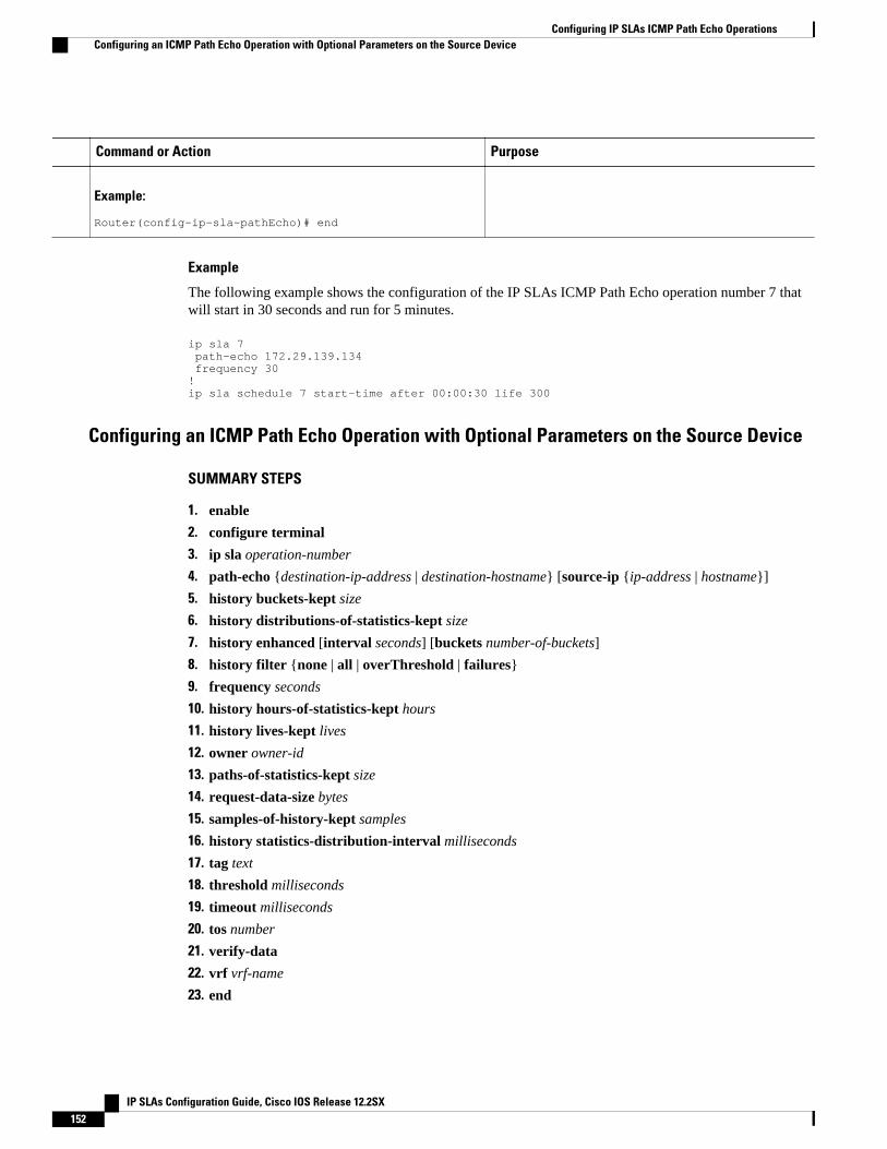
Command or Action Purpose
Example:
Router(config-ip-sla-pathEcho)# end
Example
The following example shows the configuration of the IP SLAs ICMP Path Echo operation number 7 thatwill start in 30 seconds and run for 5 minutes.
ip sla 7 path-echo 172.29.139.134 frequency 30!ip sla schedule 7 start-time after 00:00:30 life 300
Configuring an ICMP Path Echo Operation with Optional Parameters on the Source Device
SUMMARY STEPS
1. enable
2. configure terminal
3. ip sla operation-number
4. path-echo {destination-ip-address | destination-hostname} [source-ip {ip-address | hostname}]
5. history buckets-kept size
6. history distributions-of-statistics-kept size
7. history enhanced [interval seconds] [buckets number-of-buckets]
8. history filter {none | all | overThreshold | failures}
9. frequency seconds
10. history hours-of-statistics-kept hours
11. history lives-kept lives
12. owner owner-id
13. paths-of-statistics-kept size
14. request-data-size bytes
15. samples-of-history-kept samples
16. history statistics-distribution-interval milliseconds
17. tag text
18. threshold milliseconds
19. timeout milliseconds
20. tos number
21. verify-data
22. vrf vrf-name
23. end
Configuring IP SLAs ICMP Path Echo Operations Configuring an ICMP Path Echo Operation with Optional Parameters on the Source Device
IP SLAs Configuration Guide, Cisco IOS Release 12.2SX152
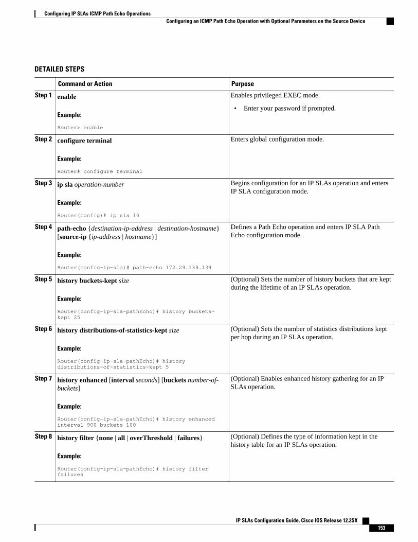
DETAILED STEPS
Command or Action Purpose
Step 1 enable
Example:
Router> enable
Enables privileged EXEC mode.
• Enter your password if prompted.
Step 2 configure terminal
Example:
Router# configure terminal
Enters global configuration mode.
Step 3 ip sla operation-number
Example:
Router(config)# ip sla 10
Begins configuration for an IP SLAs operation and entersIP SLA configuration mode.
Step 4 path-echo {destination-ip-address | destination-hostname}[source-ip {ip-address | hostname}]
Example:
Router(config-ip-sla)# path-echo 172.29.139.134
Defines a Path Echo operation and enters IP SLA PathEcho configuration mode.
Step 5 history buckets-kept size
Example:
Router(config-ip-sla-pathEcho)# history buckets-kept 25
(Optional) Sets the number of history buckets that are keptduring the lifetime of an IP SLAs operation.
Step 6 history distributions-of-statistics-kept size
Example:
Router(config-ip-sla-pathEcho)# history distributions-of-statistics-kept 5
(Optional) Sets the number of statistics distributions keptper hop during an IP SLAs operation.
Step 7 history enhanced [interval seconds] [buckets number-of-buckets]
Example:
Router(config-ip-sla-pathEcho)# history enhanced interval 900 buckets 100
(Optional) Enables enhanced history gathering for an IPSLAs operation.
Step 8 history filter {none | all | overThreshold | failures}
Example:
Router(config-ip-sla-pathEcho)# history filter failures
(Optional) Defines the type of information kept in thehistory table for an IP SLAs operation.
Configuring IP SLAs ICMP Path Echo OperationsConfiguring an ICMP Path Echo Operation with Optional Parameters on the Source Device
IP SLAs Configuration Guide, Cisco IOS Release 12.2SX 153
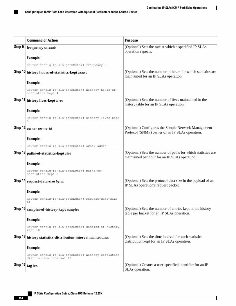
Command or Action Purpose
Step 9 frequency seconds
Example:
Router(config-ip-sla-pathEcho)# frequency 30
(Optional) Sets the rate at which a specified IP SLAsoperation repeats.
Step 10 history hours-of-statistics-kept hours
Example:
Router(config-ip-sla-pathEcho)# history hours-of-statistics-kept 4
(Optional) Sets the number of hours for which statistics aremaintained for an IP SLAs operation.
Step 11 history lives-kept lives
Example:
Router(config-ip-sla-pathEcho)# history lives-kept 5
(Optional) Sets the number of lives maintained in thehistory table for an IP SLAs operation.
Step 12 owner owner-id
Example:
Router(config-ip-sla-pathEcho)# owner admin
(Optional) Configures the Simple Network ManagementProtocol (SNMP) owner of an IP SLAs operation.
Step 13 paths-of-statistics-kept size
Example:
Router(config-ip-sla-pathEcho)# paths-of-statistics-kept 3
(Optional) Sets the number of paths for which statistics aremaintained per hour for an IP SLAs operation.
Step 14 request-data-size bytes
Example:
Router(config-ip-sla-pathEcho)# request-data-size 64
(Optional) Sets the protocol data size in the payload of anIP SLAs operation's request packet.
Step 15 samples-of-history-kept samples
Example:
Router(config-ip-sla-pathEcho)# samples-of-history-kept 10
(Optional) Sets the number of entries kept in the historytable per bucket for an IP SLAs operation.
Step 16 history statistics-distribution-interval milliseconds
Example:
Router(config-ip-sla-pathEcho)# history statistics-distribution-interval 10
(Optional) Sets the time interval for each statisticsdistribution kept for an IP SLAs operation.
Step 17 tag text (Optional) Creates a user-specified identifier for an IPSLAs operation.
Configuring IP SLAs ICMP Path Echo Operations Configuring an ICMP Path Echo Operation with Optional Parameters on the Source Device
IP SLAs Configuration Guide, Cisco IOS Release 12.2SX154
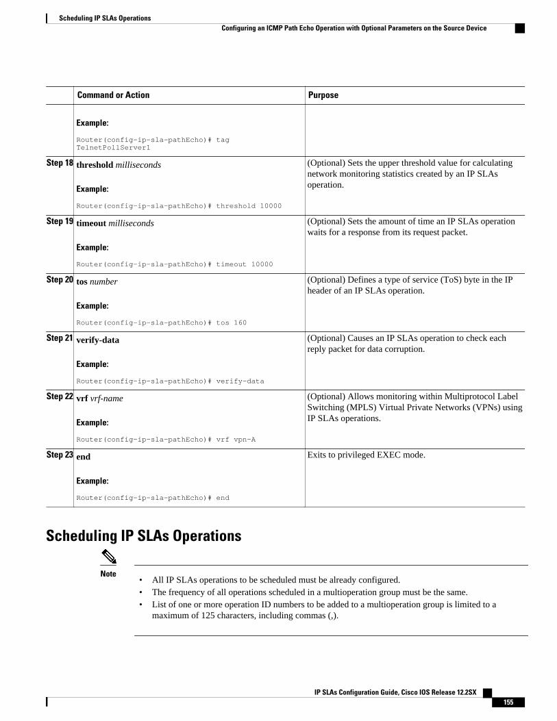
Command or Action Purpose
Example:
Router(config-ip-sla-pathEcho)# tag TelnetPollServer1
Step 18 threshold milliseconds
Example:
Router(config-ip-sla-pathEcho)# threshold 10000
(Optional) Sets the upper threshold value for calculatingnetwork monitoring statistics created by an IP SLAsoperation.
Step 19 timeout milliseconds
Example:
Router(config-ip-sla-pathEcho)# timeout 10000
(Optional) Sets the amount of time an IP SLAs operationwaits for a response from its request packet.
Step 20 tos number
Example:
Router(config-ip-sla-pathEcho)# tos 160
(Optional) Defines a type of service (ToS) byte in the IPheader of an IP SLAs operation.
Step 21 verify-data
Example:
Router(config-ip-sla-pathEcho)# verify-data
(Optional) Causes an IP SLAs operation to check eachreply packet for data corruption.
Step 22 vrf vrf-name
Example:
Router(config-ip-sla-pathEcho)# vrf vpn-A
(Optional) Allows monitoring within Multiprotocol LabelSwitching (MPLS) Virtual Private Networks (VPNs) usingIP SLAs operations.
Step 23 end
Example:
Router(config-ip-sla-pathEcho)# end
Exits to privileged EXEC mode.
Scheduling IP SLAs Operations
Note• All IP SLAs operations to be scheduled must be already configured.• The frequency of all operations scheduled in a multioperation group must be the same.• List of one or more operation ID numbers to be added to a multioperation group is limited to a
maximum of 125 characters, including commas (,).
Scheduling IP SLAs OperationsConfiguring an ICMP Path Echo Operation with Optional Parameters on the Source Device
IP SLAs Configuration Guide, Cisco IOS Release 12.2SX 155
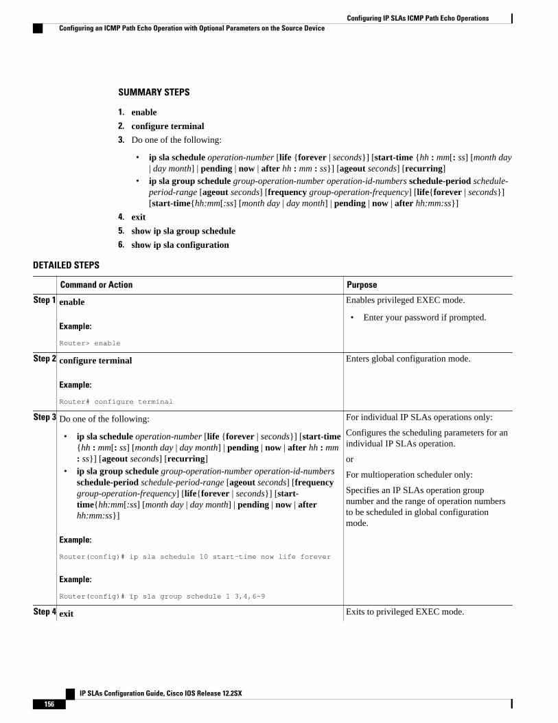
SUMMARY STEPS
1. enable
2. configure terminal
3. Do one of the following:
• ip sla schedule operation-number [life {forever | seconds}] [start-time {hh : mm[: ss] [month day| day month] | pending | now | after hh : mm : ss}] [ageout seconds] [recurring]
• ip sla group schedule group-operation-number operation-id-numbers schedule-period schedule-period-range [ageout seconds] [frequency group-operation-frequency] [life{forever | seconds}][start-time{hh:mm[:ss] [month day | day month] | pending | now | after hh:mm:ss}]
4. exit
5. show ip sla group schedule
6. show ip sla configuration
DETAILED STEPS
Command or Action Purpose
Step 1 enable
Example:
Router> enable
Enables privileged EXEC mode.
• Enter your password if prompted.
Step 2 configure terminal
Example:
Router# configure terminal
Enters global configuration mode.
Step 3 Do one of the following:
• ip sla schedule operation-number [life {forever | seconds}] [start-time{hh : mm[: ss] [month day | day month] | pending | now | after hh : mm: ss}] [ageout seconds] [recurring]
• ip sla group schedule group-operation-number operation-id-numbersschedule-period schedule-period-range [ageout seconds] [frequencygroup-operation-frequency] [life{forever | seconds}] [start-time{hh:mm[:ss] [month day | day month] | pending | now | afterhh:mm:ss}]
Example:
Router(config)# ip sla schedule 10 start-time now life forever
Example:
Router(config)# ip sla group schedule 1 3,4,6-9
For individual IP SLAs operations only:
Configures the scheduling parameters for anindividual IP SLAs operation.
or
For multioperation scheduler only:
Specifies an IP SLAs operation groupnumber and the range of operation numbersto be scheduled in global configurationmode.
Step 4 exit Exits to privileged EXEC mode.
Configuring IP SLAs ICMP Path Echo Operations Configuring an ICMP Path Echo Operation with Optional Parameters on the Source Device
IP SLAs Configuration Guide, Cisco IOS Release 12.2SX156
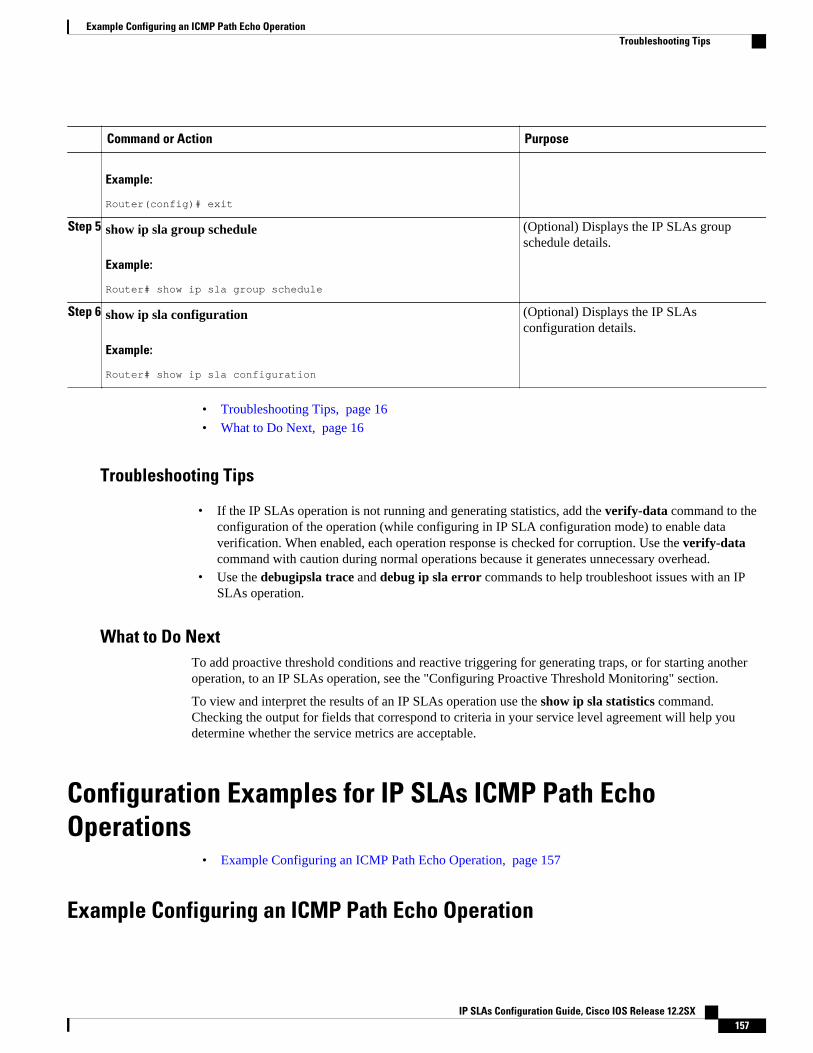
Command or Action Purpose
Example:
Router(config)# exit
Step 5 show ip sla group schedule
Example:
Router# show ip sla group schedule
(Optional) Displays the IP SLAs groupschedule details.
Step 6 show ip sla configuration
Example:
Router# show ip sla configuration
(Optional) Displays the IP SLAsconfiguration details.
• Troubleshooting Tips, page 16
• What to Do Next, page 16
Troubleshooting Tips
• If the IP SLAs operation is not running and generating statistics, add the verify-data command to theconfiguration of the operation (while configuring in IP SLA configuration mode) to enable dataverification. When enabled, each operation response is checked for corruption. Use the verify-datacommand with caution during normal operations because it generates unnecessary overhead.
• Use the debugipsla trace and debug ip sla error commands to help troubleshoot issues with an IPSLAs operation.
What to Do NextTo add proactive threshold conditions and reactive triggering for generating traps, or for starting anotheroperation, to an IP SLAs operation, see the "Configuring Proactive Threshold Monitoring" section.
To view and interpret the results of an IP SLAs operation use the show ip sla statistics command.Checking the output for fields that correspond to criteria in your service level agreement will help youdetermine whether the service metrics are acceptable.
Configuration Examples for IP SLAs ICMP Path EchoOperations
• Example Configuring an ICMP Path Echo Operation, page 157
Example Configuring an ICMP Path Echo Operation
Example Configuring an ICMP Path Echo OperationTroubleshooting Tips
IP SLAs Configuration Guide, Cisco IOS Release 12.2SX 157
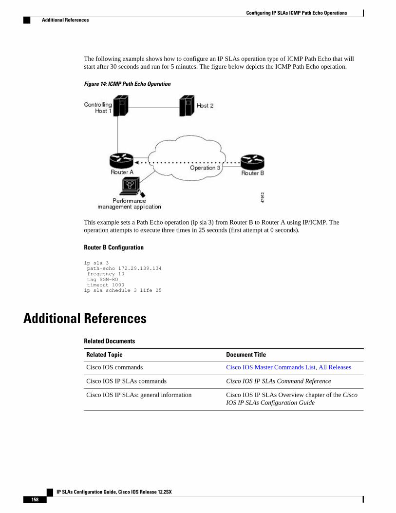
The following example shows how to configure an IP SLAs operation type of ICMP Path Echo that willstart after 30 seconds and run for 5 minutes. The figure below depicts the ICMP Path Echo operation.
Figure 14: ICMP Path Echo Operation
This example sets a Path Echo operation (ip sla 3) from Router B to Router A using IP/ICMP. Theoperation attempts to execute three times in 25 seconds (first attempt at 0 seconds).
Router B Configuration
ip sla 3 path-echo 172.29.139.134 frequency 10 tag SGN-RO timeout 1000ip sla schedule 3 life 25
Additional ReferencesRelated Documents
Related Topic Document Title
Cisco IOS commands Cisco IOS Master Commands List, All Releases
Cisco IOS IP SLAs commands Cisco IOS IP SLAs Command Reference
Cisco IOS IP SLAs: general information Cisco IOS IP SLAs Overview chapter of the CiscoIOS IP SLAs Configuration Guide
Configuring IP SLAs ICMP Path Echo Operations Additional References
IP SLAs Configuration Guide, Cisco IOS Release 12.2SX158
Standards
Standards Title
No new or modified standards are supported by thisfeature, and support for existing standards has notbeen modified by this feature.
--
MIBs
MIBs MIBs Link
CISCO-RTTMON-MIB To locate and download MIBs for selectedplatforms, Cisco IOS releases, and feature sets, useCisco MIB Locator found at the following URL:
http://www.cisco.com/go/mibs
RFCs
RFCs Title
RFC 862 Echo Protocol
Technical Assistance
Description Link
The Cisco Support and Documentation websiteprovides online resources to downloaddocumentation, software, and tools. Use theseresources to install and configure the software andto troubleshoot and resolve technical issues withCisco products and technologies. Access to mosttools on the Cisco Support and Documentationwebsite requires a Cisco.com user ID andpassword.
http://www.cisco.com/cisco/web/support/index.html
Feature Information for IP SLAs ICMP Path Echo OperationsThe following table provides release information about the feature or features described in this module.This table lists only the software release that introduced support for a given feature in a given softwarerelease train. Unless noted otherwise, subsequent releases of that software release train also support thatfeature.
Use Cisco Feature Navigator to find information about platform support and Cisco software image support.To access Cisco Feature Navigator, go to www.cisco.com/go/cfn. An account on Cisco.com is not required.
Configuring IP SLAs ICMP Path Echo OperationsFeature Information for IP SLAs ICMP Path Echo Operations
IP SLAs Configuration Guide, Cisco IOS Release 12.2SX 159
Table 18: Feature Information for IP SLAs ICMP Path Echo Operations
Feature Name Releases Feature Information
IP SLAs ICMP Path EchoOperation
12.2(31)SB2 12.2(33)SRB112.2(33)SXH 12.3(14)T 15.0(1)SCisco IOS XE 3.1.0SG
The Cisco IOS IP SLAs InternetControl Message Protocol(ICMP) path echo operationallows you to measure end-to-endand hop-by-hop network responsetime between a Cisco device andother devices using IP.
Cisco and the Cisco Logo are trademarks of Cisco Systems, Inc. and/or its affiliates in the U.S. and othercountries. A listing of Cisco's trademarks can be found at www.cisco.com/go/trademarks. Third partytrademarks mentioned are the property of their respective owners. The use of the word partner does notimply a partnership relationship between Cisco and any other company. (1005R)
Any Internet Protocol (IP) addresses and phone numbers used in this document are not intended to beactual addresses and phone numbers. Any examples, command display output, network topology diagrams,and other figures included in the document are shown for illustrative purposes only. Any use of actual IPaddresses or phone numbers in illustrative content is unintentional and coincidental.
Configuring IP SLAs ICMP Path Echo Operations
IP SLAs Configuration Guide, Cisco IOS Release 12.2SX160
Configuring IP SLAs ICMP Path JitterOperations
This document describes how to configure an IP Service Level Agreements (SLAs) Internet ControlMessage Protocol (ICMP) Path Jitter operation to monitor hop-by-hop jitter (inter-packet delay variance).This document also demonstrates how the data gathered using the Path Jitter operations can be displayedand analyzed using Cisco commands.
• Finding Feature Information, page 161• Prerequisites for ICMP Path Jitter Operations, page 161• Restrictions for ICMP Path Jitter Operations, page 162• Information About IP SLAs ICMP Path Jitter Operations, page 162• How to Configure the IP SLAs ICMP Path Jitter Operation, page 163• Configuration Examples for IP SLAs ICMP Path Jitter Operations, page 169• Additional References, page 170• Feature Information for IP SLAs ICMP Path Jitter Operations, page 171
Finding Feature InformationYour software release may not support all the features documented in this module. For the latest featureinformation and caveats, see the release notes for your platform and software release. To find informationabout the features documented in this module, and to see a list of the releases in which each feature issupported, see the Feature Information Table at the end of this document.
Use Cisco Feature Navigator to find information about platform support and Cisco software image support.To access Cisco Feature Navigator, go to www.cisco.com/go/cfn. An account on Cisco.com is not required.
Prerequisites for ICMP Path Jitter Operations• Before configuring any IP SLAs application, you can use the show ip sla application command to
verify that the operation type is supported on your software image.• In contrast with other IP SLAs operations, the IP SLAs Responder does not have to be enabled on
either the target device or intermediate devices for Path Jitter operations. However, the operationalefficiency may improve if you enable the IP SLAs Responder.
IP SLAs Configuration Guide, Cisco IOS Release 12.2SX 161
Restrictions for ICMP Path Jitter Operations• The IP SLAs ICMP Path Jitter operation is ICMP-based. ICMP-based operations can compensate for
source processing delay but cannot compensate for target processing delay. For more robustmonitoring and verifying, use of the IP SLAs UDP Jitter operation is recommended.
• The jitter values obtained using the ICMP Path Jitter operation are approximates because ICMP doesnot provide the capability to embed processing times on routers in the packet. If the target router doesnot place ICMP packets as the highest priority, then the router will not respond properly. ICMPperformance also can be affected by the configuration of priority queueing on the router and by pingresponse.
• The path jitter operation does not support hourly statistics and hop information.• Unlike other IP SLAs operations, the ICMP Path Jitter operation is not supported in the RTTMON
MIB. Path Jitter operations can only be configured using Cisco commands and statistics can only bereturned using the show ip sla commands.
• The IP SLAs Path Jitter operation does not support the IP SLAs History feature (statistics historybuckets) because of the large data volume involved with Jitter operations.
• The following commands, available in Path Jitter configuration mode, do not apply to Path Jitteroperations:
◦ history buckets-kept◦ history distributions-of-statistics-kept◦ history enhanced◦ history filter◦ history hours-of-statistics-kept◦ history lives-kept◦ history statistics-distribution-interval◦ samples-of-history-kept◦ lsr-path◦ tos◦ threshold◦ verify-data
Information About IP SLAs ICMP Path Jitter Operations• ICMP Path Jitter Operation, page 162
ICMP Path Jitter OperationThe IP SLAs ICMP Path Jitter operation provides hop-by-hop jitter, packet loss, and delay measurementstatistics in an IP network. The Path Jitter operation functions differently than the standard UDP Jitteroperation, which provides total one-way data and total round-trip data.
The ICMP Path Jitter operation can be used a supplement to the standard UDP Jitter operation. Forexample, results from the UDP Jitter operation may indicate unexpected delays or high jitter values; theICMP Path Jitter operation could then be used to troubleshoot the network path and determine if traffic isbottlenecking in a particular segment along the transmission path.
ICMP Path Jitter Operation Restrictions for ICMP Path Jitter Operations
IP SLAs Configuration Guide, Cisco IOS Release 12.2SX162
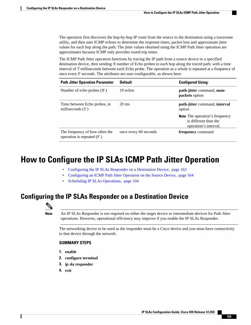
The operation first discovers the hop-by-hop IP route from the source to the destination using a tracerouteutility, and then uses ICMP echoes to determine the response times, packet loss and approximate jittervalues for each hop along the path. The jitter values obtained using the ICMP Path Jitter operation areapproximates because ICMP only provides round trip times.
The ICMP Path Jitter operation functions by tracing the IP path from a source device to a specifieddestination device, then sending N number of Echo probes to each hop along the traced path, with a timeinterval of T milliseconds between each Echo probe. The operation as a whole is repeated at a frequency ofonce every F seconds. The attributes are user-configurable, as shown here:
Path Jitter Operation Parameter Default Configured Using:
Number of echo probes (N ) 10 echos path-jitter command, num-packets option
Time between Echo probes, inmilliseconds (T )
20 ms path-jitter command, intervaloption
Note The operation’s frequencyis different than theoperation’s interval.
The frequency of how often theoperation is repeated (F )
once every 60 seconds frequency command
How to Configure the IP SLAs ICMP Path Jitter Operation• Configuring the IP SLAs Responder on a Destination Device, page 163
• Configuring an ICMP Path Jitter Operation on the Source Device, page 164
• Scheduling IP SLAs Operations, page 104
Configuring the IP SLAs Responder on a Destination Device
Note An IP SLAs Responder is not required on either the target device or intermediate devices for Path Jitteroperations. However, operational efficiency may improve if you enable the IP SLAs Responder.
The networking device to be used as the responder must be a Cisco device and you must have connectivityto that device through the network.
SUMMARY STEPS
1. enable
2. configure terminal
3. ip sla responder
4. exit
Configuring the IP SLAs Responder on a Destination DeviceHow to Configure the IP SLAs ICMP Path Jitter Operation
IP SLAs Configuration Guide, Cisco IOS Release 12.2SX 163
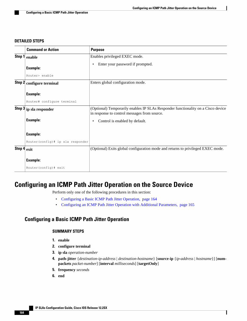
DETAILED STEPS
Command or Action Purpose
Step 1 enable
Example:
Router> enable
Enables privileged EXEC mode.
• Enter your password if prompted.
Step 2 configure terminal
Example:
Router# configure terminal
Enters global configuration mode.
Step 3 ip sla responder
Example:
Example:
Router(config)# ip sla responder
(Optional) Temporarily enables IP SLAs Responder functionality on a Cisco devicein response to control messages from source.
• Control is enabled by default.
Step 4 exit
Example:
Router(config)# exit
(Optional) Exits global configuration mode and returns to privileged EXEC mode.
Configuring an ICMP Path Jitter Operation on the Source DevicePerform only one of the following procedures in this section:
• Configuring a Basic ICMP Path Jitter Operation, page 164
• Configuring an ICMP Path Jitter Operation with Additional Parameters, page 165
Configuring a Basic ICMP Path Jitter Operation
SUMMARY STEPS
1. enable
2. configure terminal
3. ip sla operation-number
4. path-jitter {destination-ip-address | destination-hostname} [source-ip {ip-address | hostname}] [num-packets packet-number] [interval milliseconds] [targetOnly]
5. frequency seconds
6. end
Configuring an ICMP Path Jitter Operation on the Source Device Configuring a Basic ICMP Path Jitter Operation
IP SLAs Configuration Guide, Cisco IOS Release 12.2SX164
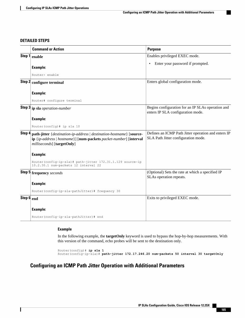
DETAILED STEPS
Command or Action Purpose
Step 1 enable
Example:
Router> enable
Enables privileged EXEC mode.
• Enter your password if prompted.
Step 2 configure terminal
Example:
Router# configure terminal
Enters global configuration mode.
Step 3 ip sla operation-number
Example:
Router(config)# ip sla 10
Begins configuration for an IP SLAs operation andenters IP SLA configuration mode.
Step 4 path-jitter {destination-ip-address | destination-hostname} [source-ip {ip-address | hostname}] [num-packets packet-number] [intervalmilliseconds] [targetOnly]
Example:
Router(config-ip-sla)# path-jitter 172.31.1.129 source-ip 10.2.30.1 num-packets 12 interval 22
Defines an ICMP Path Jitter operation and enters IPSLA Path Jitter configuration mode.
Step 5 frequency seconds
Example:
Router(config-ip-sla-pathJitter)# frequency 30
(Optional) Sets the rate at which a specified IPSLAs operation repeats.
Step 6 end
Example:
Router(config-ip-sla-pathJitter)# end
Exits to privileged EXEC mode.
Example
In the following example, the targetOnly keyword is used to bypass the hop-by-hop measurements. Withthis version of the command, echo probes will be sent to the destination only.
Router(config)# ip sla 1Router(config-ip-sla)# path-jitter 172.17.246.20 num-packets 50 interval 30 targetOnly
Configuring an ICMP Path Jitter Operation with Additional Parameters
Configuring IP SLAs ICMP Path Jitter OperationsConfiguring an ICMP Path Jitter Operation with Additional Parameters
IP SLAs Configuration Guide, Cisco IOS Release 12.2SX 165
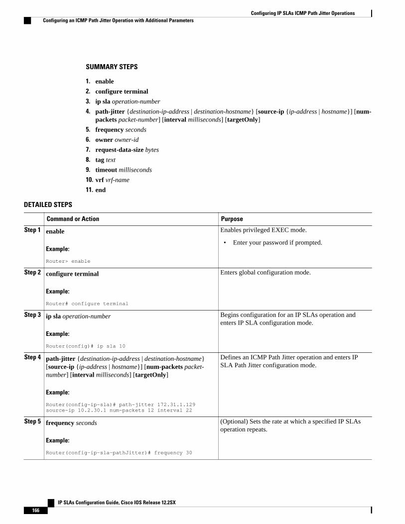
SUMMARY STEPS
1. enable
2. configure terminal
3. ip sla operation-number
4. path-jitter {destination-ip-address | destination-hostname} [source-ip {ip-address | hostname}] [num-packets packet-number] [interval milliseconds] [targetOnly]
5. frequency seconds
6. owner owner-id
7. request-data-size bytes
8. tag text
9. timeout milliseconds
10. vrf vrf-name
11. end
DETAILED STEPS
Command or Action Purpose
Step 1 enable
Example:
Router> enable
Enables privileged EXEC mode.
• Enter your password if prompted.
Step 2 configure terminal
Example:
Router# configure terminal
Enters global configuration mode.
Step 3 ip sla operation-number
Example:
Router(config)# ip sla 10
Begins configuration for an IP SLAs operation andenters IP SLA configuration mode.
Step 4 path-jitter {destination-ip-address | destination-hostname}[source-ip {ip-address | hostname}] [num-packets packet-number] [interval milliseconds] [targetOnly]
Example:
Router(config-ip-sla)# path-jitter 172.31.1.129 source-ip 10.2.30.1 num-packets 12 interval 22
Defines an ICMP Path Jitter operation and enters IPSLA Path Jitter configuration mode.
Step 5 frequency seconds
Example:
Router(config-ip-sla-pathJitter)# frequency 30
(Optional) Sets the rate at which a specified IP SLAsoperation repeats.
Configuring IP SLAs ICMP Path Jitter Operations Configuring an ICMP Path Jitter Operation with Additional Parameters
IP SLAs Configuration Guide, Cisco IOS Release 12.2SX166
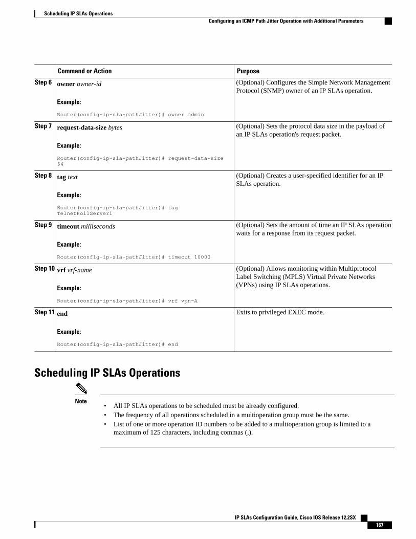
Command or Action Purpose
Step 6 owner owner-id
Example:
Router(config-ip-sla-pathJitter)# owner admin
(Optional) Configures the Simple Network ManagementProtocol (SNMP) owner of an IP SLAs operation.
Step 7 request-data-size bytes
Example:
Router(config-ip-sla-pathJitter)# request-data-size 64
(Optional) Sets the protocol data size in the payload ofan IP SLAs operation's request packet.
Step 8 tag text
Example:
Router(config-ip-sla-pathJitter)# tag TelnetPollServer1
(Optional) Creates a user-specified identifier for an IPSLAs operation.
Step 9 timeout milliseconds
Example:
Router(config-ip-sla-pathJitter)# timeout 10000
(Optional) Sets the amount of time an IP SLAs operationwaits for a response from its request packet.
Step 10 vrf vrf-name
Example:
Router(config-ip-sla-pathJitter)# vrf vpn-A
(Optional) Allows monitoring within MultiprotocolLabel Switching (MPLS) Virtual Private Networks(VPNs) using IP SLAs operations.
Step 11 end
Example:
Router(config-ip-sla-pathJitter)# end
Exits to privileged EXEC mode.
Scheduling IP SLAs Operations
Note• All IP SLAs operations to be scheduled must be already configured.• The frequency of all operations scheduled in a multioperation group must be the same.• List of one or more operation ID numbers to be added to a multioperation group is limited to a
maximum of 125 characters, including commas (,).
Scheduling IP SLAs OperationsConfiguring an ICMP Path Jitter Operation with Additional Parameters
IP SLAs Configuration Guide, Cisco IOS Release 12.2SX 167

SUMMARY STEPS
1. enable
2. configure terminal
3. Do one of the following:
• ip sla schedule operation-number [life {forever | seconds}] [start-time {hh : mm[: ss] [month day| day month] | pending | now | after hh : mm : ss}] [ageout seconds] [recurring]
• ip sla group schedule group-operation-number operation-id-numbers schedule-period schedule-period-range [ageout seconds] [frequency group-operation-frequency] [life{forever | seconds}][start-time{hh:mm[:ss] [month day | day month] | pending | now | after hh:mm:ss}]
4. exit
5. show ip sla group schedule
6. show ip sla configuration
DETAILED STEPS
Command or Action Purpose
Step 1 enable
Example:
Router> enable
Enables privileged EXEC mode.
• Enter your password if prompted.
Step 2 configure terminal
Example:
Router# configure terminal
Enters global configuration mode.
Step 3 Do one of the following:
• ip sla schedule operation-number [life {forever | seconds}] [start-time{hh : mm[: ss] [month day | day month] | pending | now | after hh : mm: ss}] [ageout seconds] [recurring]
• ip sla group schedule group-operation-number operation-id-numbersschedule-period schedule-period-range [ageout seconds] [frequencygroup-operation-frequency] [life{forever | seconds}] [start-time{hh:mm[:ss] [month day | day month] | pending | now | afterhh:mm:ss}]
Example:
Router(config)# ip sla schedule 10 start-time now life forever
Example:
Router(config)# ip sla group schedule 1 3,4,6-9
For individual IP SLAs operations only:
Configures the scheduling parameters for anindividual IP SLAs operation.
or
For multioperation scheduler only:
Specifies an IP SLAs operation groupnumber and the range of operation numbersto be scheduled in global configurationmode.
Step 4 exit Exits to privileged EXEC mode.
Configuring IP SLAs ICMP Path Jitter Operations Configuring an ICMP Path Jitter Operation with Additional Parameters
IP SLAs Configuration Guide, Cisco IOS Release 12.2SX168
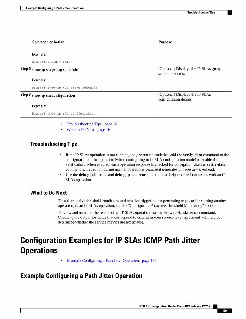
Command or Action Purpose
Example:
Router(config)# exit
Step 5 show ip sla group schedule
Example:
Router# show ip sla group schedule
(Optional) Displays the IP SLAs groupschedule details.
Step 6 show ip sla configuration
Example:
Router# show ip sla configuration
(Optional) Displays the IP SLAsconfiguration details.
• Troubleshooting Tips, page 16
• What to Do Next, page 16
Troubleshooting Tips
• If the IP SLAs operation is not running and generating statistics, add the verify-data command to theconfiguration of the operation (while configuring in IP SLA configuration mode) to enable dataverification. When enabled, each operation response is checked for corruption. Use the verify-datacommand with caution during normal operations because it generates unnecessary overhead.
• Use the debugipsla trace and debug ip sla error commands to help troubleshoot issues with an IPSLAs operation.
What to Do NextTo add proactive threshold conditions and reactive triggering for generating traps, or for starting anotheroperation, to an IP SLAs operation, see the "Configuring Proactive Threshold Monitoring" section.
To view and interpret the results of an IP SLAs operation use the show ip sla statistics command.Checking the output for fields that correspond to criteria in your service level agreement will help youdetermine whether the service metrics are acceptable.
Configuration Examples for IP SLAs ICMP Path JitterOperations
• Example Configuring a Path Jitter Operation, page 169
Example Configuring a Path Jitter Operation
Example Configuring a Path Jitter OperationTroubleshooting Tips
IP SLAs Configuration Guide, Cisco IOS Release 12.2SX 169
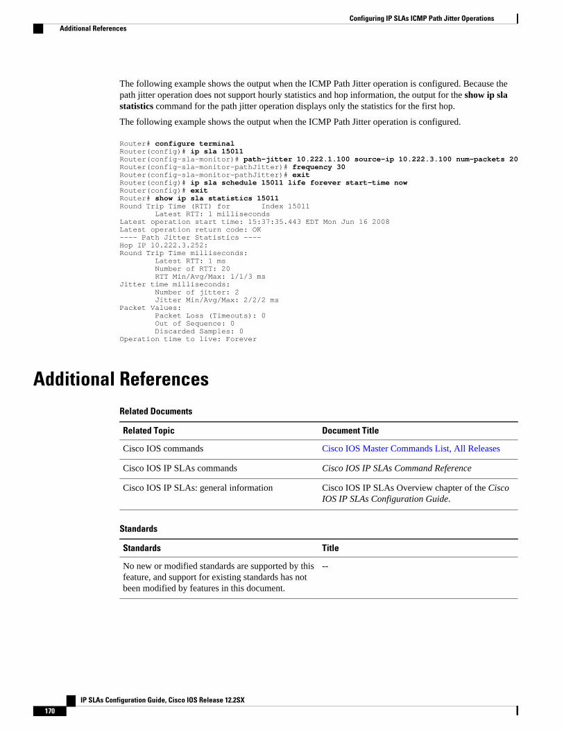
The following example shows the output when the ICMP Path Jitter operation is configured. Because thepath jitter operation does not support hourly statistics and hop information, the output for the show ip slastatistics command for the path jitter operation displays only the statistics for the first hop.
The following example shows the output when the ICMP Path Jitter operation is configured.
Router# configure terminalRouter(config)# ip sla 15011Router(config-sla-monitor)# path-jitter 10.222.1.100 source-ip 10.222.3.100 num-packets 20Router(config-sla-monitor-pathJitter)# frequency 30Router(config-sla-monitor-pathJitter)# exitRouter(config)# ip sla schedule 15011 life forever start-time nowRouter(config)# exitRouter# show ip sla statistics 15011Round Trip Time (RTT) for Index 15011 Latest RTT: 1 millisecondsLatest operation start time: 15:37:35.443 EDT Mon Jun 16 2008Latest operation return code: OK---- Path Jitter Statistics ---- Hop IP 10.222.3.252:Round Trip Time milliseconds: Latest RTT: 1 ms Number of RTT: 20 RTT Min/Avg/Max: 1/1/3 msJitter time milliseconds: Number of jitter: 2 Jitter Min/Avg/Max: 2/2/2 msPacket Values: Packet Loss (Timeouts): 0 Out of Sequence: 0 Discarded Samples: 0Operation time to live: Forever
Additional ReferencesRelated Documents
Related Topic Document Title
Cisco IOS commands Cisco IOS Master Commands List, All Releases
Cisco IOS IP SLAs commands Cisco IOS IP SLAs Command Reference
Cisco IOS IP SLAs: general information Cisco IOS IP SLAs Overview chapter of the CiscoIOS IP SLAs Configuration Guide.
Standards
Standards Title
No new or modified standards are supported by thisfeature, and support for existing standards has notbeen modified by features in this document.
--
Configuring IP SLAs ICMP Path Jitter Operations Additional References
IP SLAs Configuration Guide, Cisco IOS Release 12.2SX170
MIBs
MIBs MIBs Link
MIB support for the Path Jitter operation is notprovided.
To locate and download MIBs for selectedplatforms, Cisco IOS releases, and feature sets, useCisco MIB Locator found at the following URL:
http://www.cisco.com/go/mibs
RFCs
RFCs Title
RFC 18894 RTP: A Transport Protocol for Real-TimeApplications ; see the section “Estimating theInterarrival Jitter”
Technical Assistance
Description Link
The Cisco Support and Documentation websiteprovides online resources to downloaddocumentation, software, and tools. Use theseresources to install and configure the software andto troubleshoot and resolve technical issues withCisco products and technologies. Access to mosttools on the Cisco Support and Documentationwebsite requires a Cisco.com user ID andpassword.
http://www.cisco.com/cisco/web/support/index.html
Feature Information for IP SLAs ICMP Path Jitter OperationsThe following table provides release information about the feature or features described in this module.This table lists only the software release that introduced support for a given feature in a given softwarerelease train. Unless noted otherwise, subsequent releases of that software release train also support thatfeature.
Use Cisco Feature Navigator to find information about platform support and Cisco software image support.To access Cisco Feature Navigator, go to www.cisco.com/go/cfn. An account on Cisco.com is not required.
Table 19: Feature Information for IP SLAs ICMP Path Jitter Operations
Feature Name Releases Feature Information
IP SLAs Path Jitter Operation 12.2(31)SB2 12.2(33)SRB112.2(33)SXH 12.3(14)T 15.0(1)SCisco IOS XE 3.1.0SG
The Cisco IOS IP SLAs InternetControl Message Protocol(ICMP) path jitter operation
4 Support for the listed RFC is not claimed; listed as a reference only.
Configuring IP SLAs ICMP Path Jitter OperationsFeature Information for IP SLAs ICMP Path Jitter Operations
IP SLAs Configuration Guide, Cisco IOS Release 12.2SX 171
Feature Name Releases Feature Information
allows you to measure hop-by-hop jitter (inter-packet delayvariance).
Cisco and the Cisco Logo are trademarks of Cisco Systems, Inc. and/or its affiliates in the U.S. and othercountries. A listing of Cisco's trademarks can be found at www.cisco.com/go/trademarks. Third partytrademarks mentioned are the property of their respective owners. The use of the word partner does notimply a partnership relationship between Cisco and any other company. (1005R)
Any Internet Protocol (IP) addresses and phone numbers used in this document are not intended to beactual addresses and phone numbers. Any examples, command display output, network topology diagrams,and other figures included in the document are shown for illustrative purposes only. Any use of actual IPaddresses or phone numbers in illustrative content is unintentional and coincidental.
Configuring IP SLAs ICMP Path Jitter Operations
IP SLAs Configuration Guide, Cisco IOS Release 12.2SX172
Configuring IP SLAs FTP Operations
This module describes how to configure an IP Service Level Agreements (SLAs) File Transfer Protocol(FTP) operation to measure the response time between a Cisco device and a FTP server to retrieve a file.The IP SLAs FTP operation supports an FTP GET request only. This module also demonstrates how theresults of the FTP operation can be displayed and analyzed to determine the capacity of your network. TheFTP operation can be used also for troubleshooting FTP server performance.
• Finding Feature Information, page 173• Restrictions for IP SLAs FTP Operations, page 173• Information About IP SLAs FTP Operations, page 173• How to Configure IP SLAs FTP Operations, page 174• Configuration Examples for IP SLAs FTP Operations, page 181• Additional References, page 181• Feature Information for IP SLAs FTP Operations, page 182
Finding Feature InformationYour software release may not support all the features documented in this module. For the latest featureinformation and caveats, see the release notes for your platform and software release. To find informationabout the features documented in this module, and to see a list of the releases in which each feature issupported, see the Feature Information Table at the end of this document.
Use Cisco Feature Navigator to find information about platform support and Cisco software image support.To access Cisco Feature Navigator, go to www.cisco.com/go/cfn. An account on Cisco.com is not required.
Restrictions for IP SLAs FTP OperationsThe IP SLAs FTP operation only supports FTP GET (download) requests.
Information About IP SLAs FTP Operations• FTP Operation, page 174
IP SLAs Configuration Guide, Cisco IOS Release 12.2SX 173
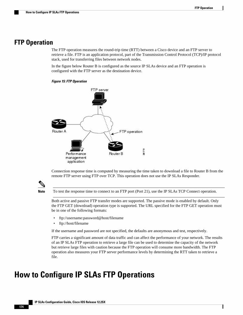
FTP OperationThe FTP operation measures the round-trip time (RTT) between a Cisco device and an FTP server toretrieve a file. FTP is an application protocol, part of the Transmission Control Protocol (TCP)/IP protocolstack, used for transferring files between network nodes.
In the figure below Router B is configured as the source IP SLAs device and an FTP operation isconfigured with the FTP server as the destination device.
Figure 15: FTP Operation
Connection response time is computed by measuring the time taken to download a file to Router B from theremote FTP server using FTP over TCP. This operation does not use the IP SLAs Responder.
Note To test the response time to connect to an FTP port (Port 21), use the IP SLAs TCP Connect operation.
Both active and passive FTP transfer modes are supported. The passive mode is enabled by default. Onlythe FTP GET (download) operation type is supported. The URL specified for the FTP GET operation mustbe in one of the following formats:
• ftp://username:password@host/filename• ftp://host/filename
If the username and password are not specified, the defaults are anonymous and test, respectively.
FTP carries a significant amount of data traffic and can affect the performance of your network. The resultsof an IP SLAs FTP operation to retrieve a large file can be used to determine the capacity of the networkbut retrieve large files with caution because the FTP operation will consume more bandwidth. The FTPoperation also measures your FTP server performance levels by determining the RTT taken to retrieve afile.
How to Configure IP SLAs FTP Operations
FTP Operation How to Configure IP SLAs FTP Operations
IP SLAs Configuration Guide, Cisco IOS Release 12.2SX174
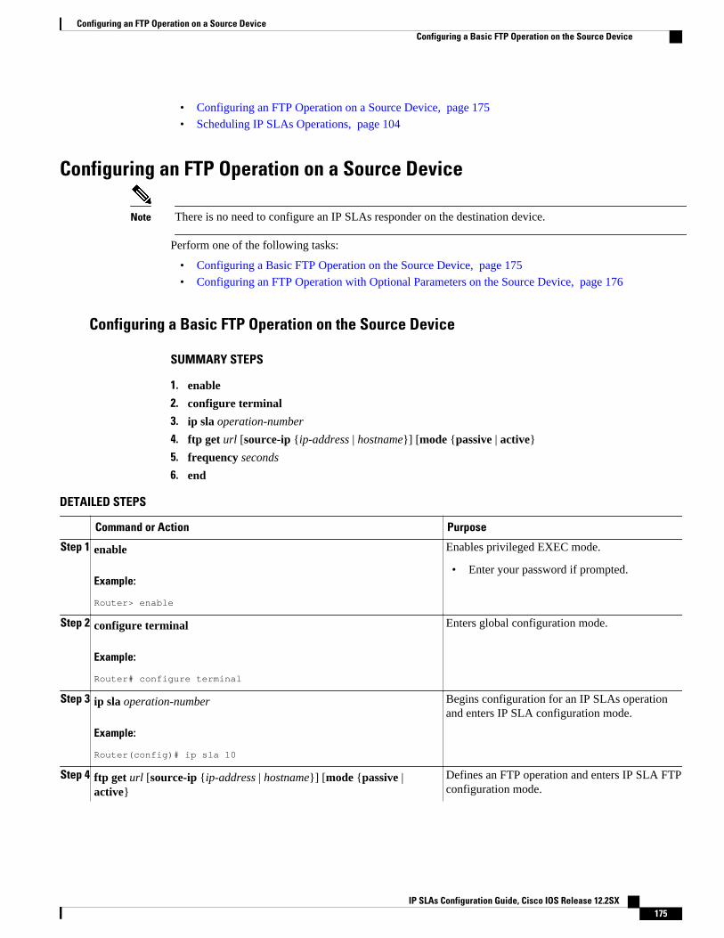
• Configuring an FTP Operation on a Source Device, page 175
• Scheduling IP SLAs Operations, page 104
Configuring an FTP Operation on a Source Device
Note There is no need to configure an IP SLAs responder on the destination device.
Perform one of the following tasks:
• Configuring a Basic FTP Operation on the Source Device, page 175
• Configuring an FTP Operation with Optional Parameters on the Source Device, page 176
Configuring a Basic FTP Operation on the Source Device
SUMMARY STEPS
1. enable
2. configure terminal
3. ip sla operation-number
4. ftp get url [source-ip {ip-address | hostname}] [mode {passive | active}
5. frequency seconds
6. end
DETAILED STEPS
Command or Action Purpose
Step 1 enable
Example:
Router> enable
Enables privileged EXEC mode.
• Enter your password if prompted.
Step 2 configure terminal
Example:
Router# configure terminal
Enters global configuration mode.
Step 3 ip sla operation-number
Example:
Router(config)# ip sla 10
Begins configuration for an IP SLAs operationand enters IP SLA configuration mode.
Step 4 ftp get url [source-ip {ip-address | hostname}] [mode {passive |active}
Defines an FTP operation and enters IP SLA FTPconfiguration mode.
Configuring an FTP Operation on a Source DeviceConfiguring a Basic FTP Operation on the Source Device
IP SLAs Configuration Guide, Cisco IOS Release 12.2SX 175
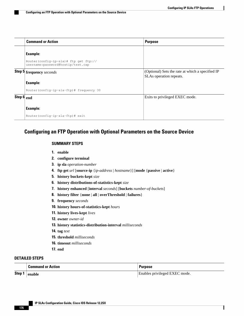
Command or Action Purpose
Example:
Router(config-ip-sla)# ftp get ftp://username:password@hostip/test.cap
Step 5 frequency seconds
Example:
Router(config-ip-sla-ftp)# frequency 30
(Optional) Sets the rate at which a specified IPSLAs operation repeats.
Step 6 end
Example:
Router(config-ip-sla-ftp)# exit
Exits to privileged EXEC mode.
Configuring an FTP Operation with Optional Parameters on the Source Device
SUMMARY STEPS
1. enable
2. configure terminal
3. ip sla operation-number
4. ftp get url [source-ip {ip-address | hostname}] [mode {passive | active}
5. history buckets-kept size
6. history distributions-of-statistics-kept size
7. history enhanced [interval seconds] [buckets number-of-buckets]
8. history filter {none | all | overThreshold | failures}
9. frequency seconds
10. history hours-of-statistics-kept hours
11. history lives-kept lives
12. owner owner-id
13. history statistics-distribution-interval milliseconds
14. tag text
15. threshold milliseconds
16. timeout milliseconds
17. end
DETAILED STEPS
Command or Action Purpose
Step 1 enable Enables privileged EXEC mode.
Configuring IP SLAs FTP Operations Configuring an FTP Operation with Optional Parameters on the Source Device
IP SLAs Configuration Guide, Cisco IOS Release 12.2SX176
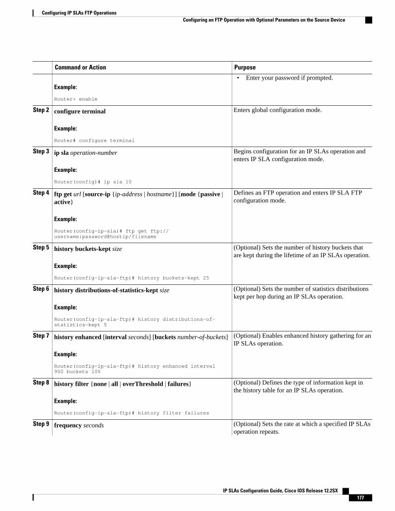
Command or Action Purpose
Example:
Router> enable
• Enter your password if prompted.
Step 2 configure terminal
Example:
Router# configure terminal
Enters global configuration mode.
Step 3 ip sla operation-number
Example:
Router(config)# ip sla 10
Begins configuration for an IP SLAs operation andenters IP SLA configuration mode.
Step 4 ftp get url [source-ip {ip-address | hostname}] [mode {passive |active}
Example:
Router(config-ip-sla)# ftp get ftp://username:password@hostip/filename
Defines an FTP operation and enters IP SLA FTPconfiguration mode.
Step 5 history buckets-kept size
Example:
Router(config-ip-sla-ftp)# history buckets-kept 25
(Optional) Sets the number of history buckets thatare kept during the lifetime of an IP SLAs operation.
Step 6 history distributions-of-statistics-kept size
Example:
Router(config-ip-sla-ftp)# history distributions-of-statistics-kept 5
(Optional) Sets the number of statistics distributionskept per hop during an IP SLAs operation.
Step 7 history enhanced [interval seconds] [buckets number-of-buckets]
Example:
Router(config-ip-sla-ftp)# history enhanced interval 900 buckets 100
(Optional) Enables enhanced history gathering for anIP SLAs operation.
Step 8 history filter {none | all | overThreshold | failures}
Example:
Router(config-ip-sla-ftp)# history filter failures
(Optional) Defines the type of information kept inthe history table for an IP SLAs operation.
Step 9 frequency seconds (Optional) Sets the rate at which a specified IP SLAsoperation repeats.
Configuring IP SLAs FTP OperationsConfiguring an FTP Operation with Optional Parameters on the Source Device
IP SLAs Configuration Guide, Cisco IOS Release 12.2SX 177
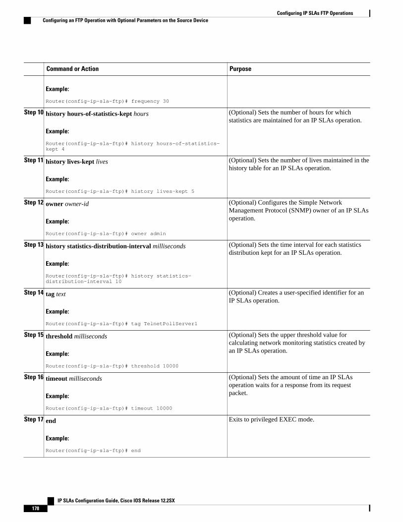
Command or Action Purpose
Example:
Router(config-ip-sla-ftp)# frequency 30
Step 10 history hours-of-statistics-kept hours
Example:
Router(config-ip-sla-ftp)# history hours-of-statistics-kept 4
(Optional) Sets the number of hours for whichstatistics are maintained for an IP SLAs operation.
Step 11 history lives-kept lives
Example:
Router(config-ip-sla-ftp)# history lives-kept 5
(Optional) Sets the number of lives maintained in thehistory table for an IP SLAs operation.
Step 12 owner owner-id
Example:
Router(config-ip-sla-ftp)# owner admin
(Optional) Configures the Simple NetworkManagement Protocol (SNMP) owner of an IP SLAsoperation.
Step 13 history statistics-distribution-interval milliseconds
Example:
Router(config-ip-sla-ftp)# history statistics-distribution-interval 10
(Optional) Sets the time interval for each statisticsdistribution kept for an IP SLAs operation.
Step 14 tag text
Example:
Router(config-ip-sla-ftp)# tag TelnetPollServer1
(Optional) Creates a user-specified identifier for anIP SLAs operation.
Step 15 threshold milliseconds
Example:
Router(config-ip-sla-ftp)# threshold 10000
(Optional) Sets the upper threshold value forcalculating network monitoring statistics created byan IP SLAs operation.
Step 16 timeout milliseconds
Example:
Router(config-ip-sla-ftp)# timeout 10000
(Optional) Sets the amount of time an IP SLAsoperation waits for a response from its requestpacket.
Step 17 end
Example:
Router(config-ip-sla-ftp)# end
Exits to privileged EXEC mode.
Configuring IP SLAs FTP Operations Configuring an FTP Operation with Optional Parameters on the Source Device
IP SLAs Configuration Guide, Cisco IOS Release 12.2SX178
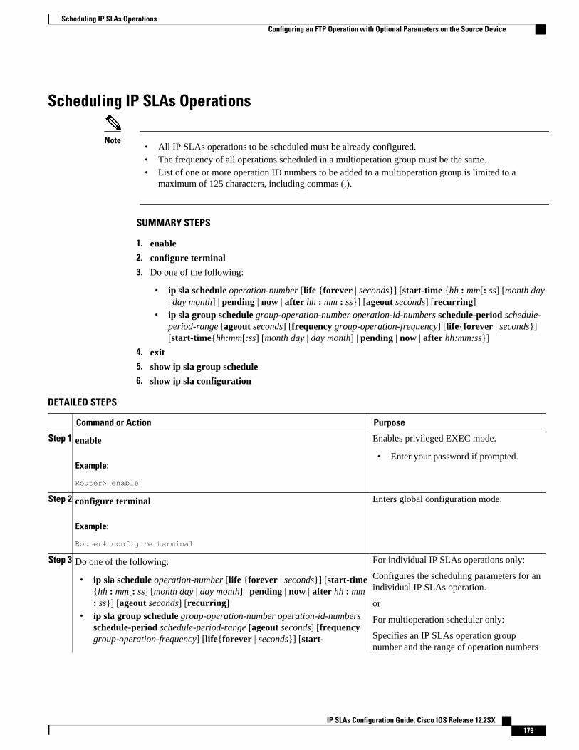
Scheduling IP SLAs Operations
Note• All IP SLAs operations to be scheduled must be already configured.• The frequency of all operations scheduled in a multioperation group must be the same.• List of one or more operation ID numbers to be added to a multioperation group is limited to a
maximum of 125 characters, including commas (,).
SUMMARY STEPS
1. enable
2. configure terminal
3. Do one of the following:
• ip sla schedule operation-number [life {forever | seconds}] [start-time {hh : mm[: ss] [month day| day month] | pending | now | after hh : mm : ss}] [ageout seconds] [recurring]
• ip sla group schedule group-operation-number operation-id-numbers schedule-period schedule-period-range [ageout seconds] [frequency group-operation-frequency] [life{forever | seconds}][start-time{hh:mm[:ss] [month day | day month] | pending | now | after hh:mm:ss}]
4. exit
5. show ip sla group schedule
6. show ip sla configuration
DETAILED STEPS
Command or Action Purpose
Step 1 enable
Example:
Router> enable
Enables privileged EXEC mode.
• Enter your password if prompted.
Step 2 configure terminal
Example:
Router# configure terminal
Enters global configuration mode.
Step 3 Do one of the following:
• ip sla schedule operation-number [life {forever | seconds}] [start-time{hh : mm[: ss] [month day | day month] | pending | now | after hh : mm: ss}] [ageout seconds] [recurring]
• ip sla group schedule group-operation-number operation-id-numbersschedule-period schedule-period-range [ageout seconds] [frequencygroup-operation-frequency] [life{forever | seconds}] [start-
For individual IP SLAs operations only:
Configures the scheduling parameters for anindividual IP SLAs operation.
or
For multioperation scheduler only:
Specifies an IP SLAs operation groupnumber and the range of operation numbers
Scheduling IP SLAs OperationsConfiguring an FTP Operation with Optional Parameters on the Source Device
IP SLAs Configuration Guide, Cisco IOS Release 12.2SX 179
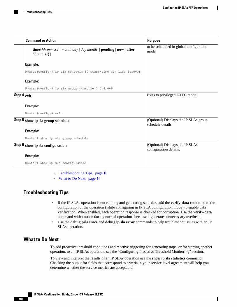
Command or Action Purpose
time{hh:mm[:ss] [month day | day month] | pending | now | afterhh:mm:ss}]
Example:
Router(config)# ip sla schedule 10 start-time now life forever
Example:
Router(config)# ip sla group schedule 1 3,4,6-9
to be scheduled in global configurationmode.
Step 4 exit
Example:
Router(config)# exit
Exits to privileged EXEC mode.
Step 5 show ip sla group schedule
Example:
Router# show ip sla group schedule
(Optional) Displays the IP SLAs groupschedule details.
Step 6 show ip sla configuration
Example:
Router# show ip sla configuration
(Optional) Displays the IP SLAsconfiguration details.
• Troubleshooting Tips, page 16
• What to Do Next, page 16
Troubleshooting Tips
• If the IP SLAs operation is not running and generating statistics, add the verify-data command to theconfiguration of the operation (while configuring in IP SLA configuration mode) to enable dataverification. When enabled, each operation response is checked for corruption. Use the verify-datacommand with caution during normal operations because it generates unnecessary overhead.
• Use the debugipsla trace and debug ip sla error commands to help troubleshoot issues with an IPSLAs operation.
What to Do NextTo add proactive threshold conditions and reactive triggering for generating traps, or for starting anotheroperation, to an IP SLAs operation, see the "Configuring Proactive Threshold Monitoring" section.
To view and interpret the results of an IP SLAs operation use the show ip sla statistics command.Checking the output for fields that correspond to criteria in your service level agreement will help youdetermine whether the service metrics are acceptable.
Configuring IP SLAs FTP Operations Troubleshooting Tips
IP SLAs Configuration Guide, Cisco IOS Release 12.2SX180
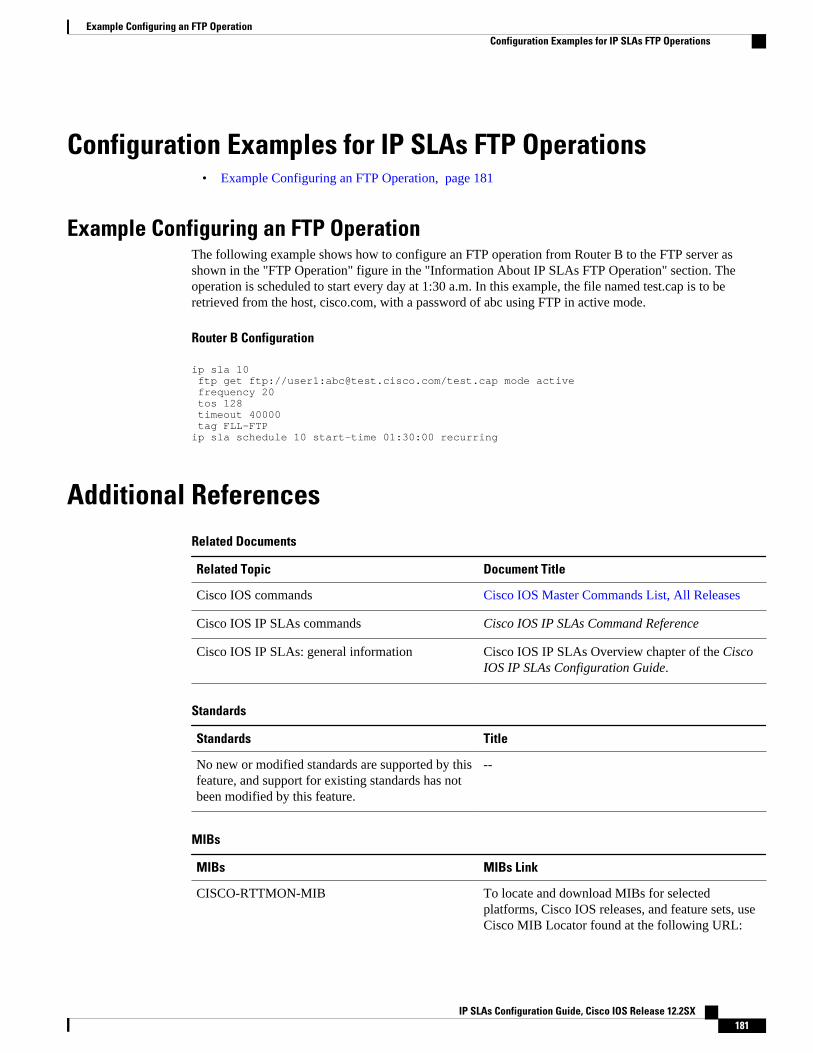
Configuration Examples for IP SLAs FTP Operations• Example Configuring an FTP Operation, page 181
Example Configuring an FTP OperationThe following example shows how to configure an FTP operation from Router B to the FTP server asshown in the "FTP Operation" figure in the "Information About IP SLAs FTP Operation" section. Theoperation is scheduled to start every day at 1:30 a.m. In this example, the file named test.cap is to beretrieved from the host, cisco.com, with a password of abc using FTP in active mode.
Router B Configuration
ip sla 10 ftp get ftp://user1:[email protected]/test.cap mode active frequency 20 tos 128 timeout 40000 tag FLL-FTPip sla schedule 10 start-time 01:30:00 recurring
Additional ReferencesRelated Documents
Related Topic Document Title
Cisco IOS commands Cisco IOS Master Commands List, All Releases
Cisco IOS IP SLAs commands Cisco IOS IP SLAs Command Reference
Cisco IOS IP SLAs: general information Cisco IOS IP SLAs Overview chapter of the CiscoIOS IP SLAs Configuration Guide.
Standards
Standards Title
No new or modified standards are supported by thisfeature, and support for existing standards has notbeen modified by this feature.
--
MIBs
MIBs MIBs Link
CISCO-RTTMON-MIB To locate and download MIBs for selectedplatforms, Cisco IOS releases, and feature sets, useCisco MIB Locator found at the following URL:
Example Configuring an FTP OperationConfiguration Examples for IP SLAs FTP Operations
IP SLAs Configuration Guide, Cisco IOS Release 12.2SX 181
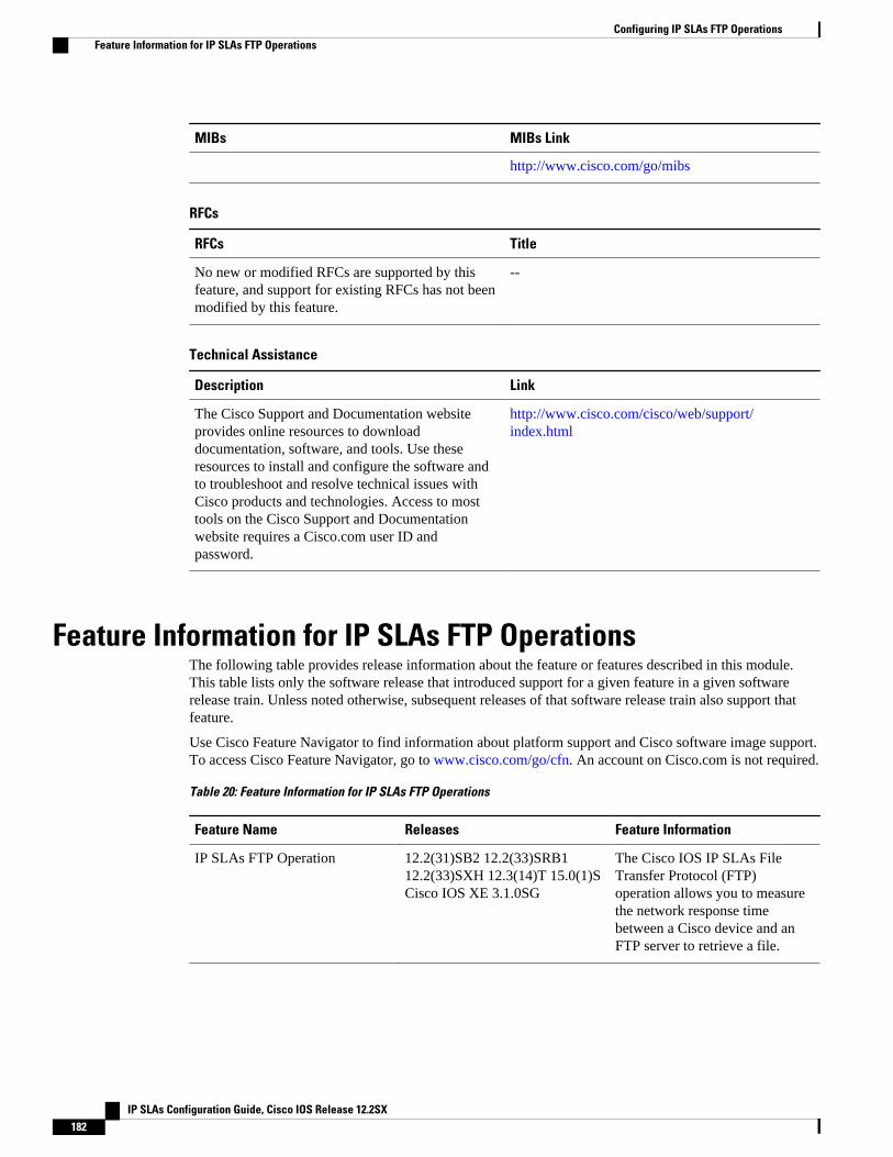
MIBs MIBs Link
http://www.cisco.com/go/mibs
RFCs
RFCs Title
No new or modified RFCs are supported by thisfeature, and support for existing RFCs has not beenmodified by this feature.
--
Technical Assistance
Description Link
The Cisco Support and Documentation websiteprovides online resources to downloaddocumentation, software, and tools. Use theseresources to install and configure the software andto troubleshoot and resolve technical issues withCisco products and technologies. Access to mosttools on the Cisco Support and Documentationwebsite requires a Cisco.com user ID andpassword.
http://www.cisco.com/cisco/web/support/index.html
Feature Information for IP SLAs FTP OperationsThe following table provides release information about the feature or features described in this module.This table lists only the software release that introduced support for a given feature in a given softwarerelease train. Unless noted otherwise, subsequent releases of that software release train also support thatfeature.
Use Cisco Feature Navigator to find information about platform support and Cisco software image support.To access Cisco Feature Navigator, go to www.cisco.com/go/cfn. An account on Cisco.com is not required.
Table 20: Feature Information for IP SLAs FTP Operations
Feature Name Releases Feature Information
IP SLAs FTP Operation 12.2(31)SB2 12.2(33)SRB112.2(33)SXH 12.3(14)T 15.0(1)SCisco IOS XE 3.1.0SG
The Cisco IOS IP SLAs FileTransfer Protocol (FTP)operation allows you to measurethe network response timebetween a Cisco device and anFTP server to retrieve a file.
Configuring IP SLAs FTP Operations Feature Information for IP SLAs FTP Operations
IP SLAs Configuration Guide, Cisco IOS Release 12.2SX182
Cisco and the Cisco Logo are trademarks of Cisco Systems, Inc. and/or its affiliates in the U.S. and othercountries. A listing of Cisco's trademarks can be found at www.cisco.com/go/trademarks. Third partytrademarks mentioned are the property of their respective owners. The use of the word partner does notimply a partnership relationship between Cisco and any other company. (1005R)
Any Internet Protocol (IP) addresses and phone numbers used in this document are not intended to beactual addresses and phone numbers. Any examples, command display output, network topology diagrams,and other figures included in the document are shown for illustrative purposes only. Any use of actual IPaddresses or phone numbers in illustrative content is unintentional and coincidental.
Configuring IP SLAs FTP Operations
IP SLAs Configuration Guide, Cisco IOS Release 12.2SX 183

Example Configuring an FTP Operation
IP SLAs Configuration Guide, Cisco IOS Release 12.2SX184
Configuring IP SLAs DNS Operations
This module describes how to configure the IP Service Level Agreements (SLAs) Domain Name System(DNS) operation to measure the difference between the time taken to send a DNS request and receive areply. This module also demonstrates how the results of the DNS operation can be displayed and analyzedto determine the DNS lookup time which is a critical element for determining the performance of a DNSor web server.
• Finding Feature Information, page 185• Information About IP SLAs DNS Operations, page 185• How to Configure IP SLAs DNS Operations, page 186• Configuration Examples for IP SLAs DNS Operations, page 192• Additional References, page 193• Feature Information for IP SLAs DNS Operations, page 194
Finding Feature InformationYour software release may not support all the features documented in this module. For the latest featureinformation and caveats, see the release notes for your platform and software release. To find informationabout the features documented in this module, and to see a list of the releases in which each feature issupported, see the Feature Information Table at the end of this document.
Use Cisco Feature Navigator to find information about platform support and Cisco software image support.To access Cisco Feature Navigator, go to www.cisco.com/go/cfn. An account on Cisco.com is not required.
Information About IP SLAs DNS Operations• DNS Operation, page 185
DNS OperationThe DNS operation measures the difference between the time taken to send a DNS request and receive areply. DNS is used in the Internet for translating names of network nodes into addresses. The IP SLAs DNSoperation queries for an IP address if you specify a host name, or queries for a host name if you specify anIP address.
IP SLAs Configuration Guide, Cisco IOS Release 12.2SX 185
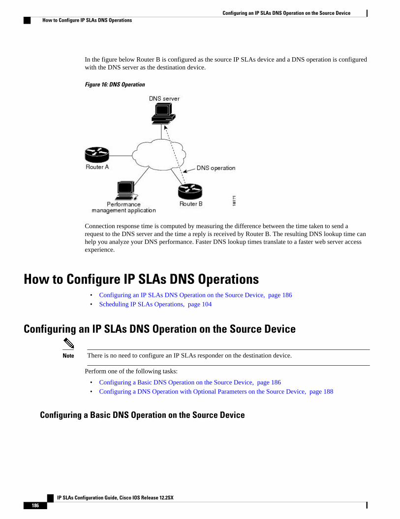
In the figure below Router B is configured as the source IP SLAs device and a DNS operation is configuredwith the DNS server as the destination device.
Figure 16: DNS Operation
Connection response time is computed by measuring the difference between the time taken to send arequest to the DNS server and the time a reply is received by Router B. The resulting DNS lookup time canhelp you analyze your DNS performance. Faster DNS lookup times translate to a faster web server accessexperience.
How to Configure IP SLAs DNS Operations• Configuring an IP SLAs DNS Operation on the Source Device, page 186
• Scheduling IP SLAs Operations, page 104
Configuring an IP SLAs DNS Operation on the Source Device
Note There is no need to configure an IP SLAs responder on the destination device.
Perform one of the following tasks:
• Configuring a Basic DNS Operation on the Source Device, page 186
• Configuring a DNS Operation with Optional Parameters on the Source Device, page 188
Configuring a Basic DNS Operation on the Source Device
Configuring an IP SLAs DNS Operation on the Source Device How to Configure IP SLAs DNS Operations
IP SLAs Configuration Guide, Cisco IOS Release 12.2SX186
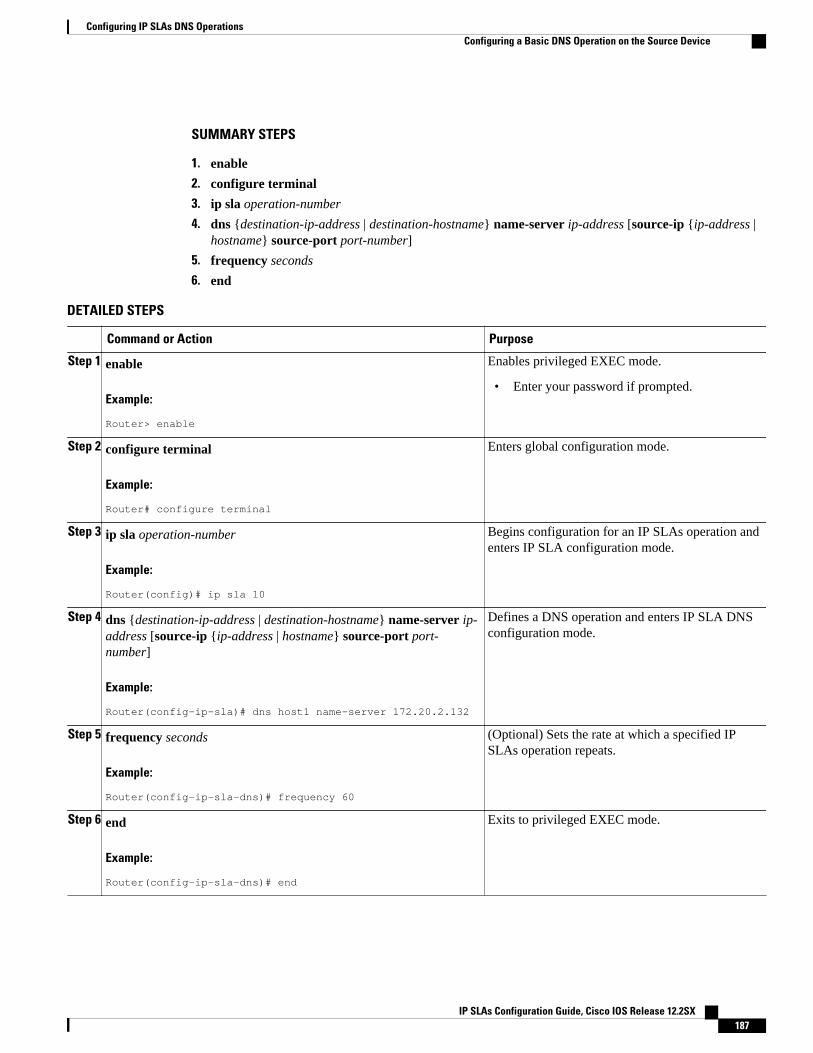
SUMMARY STEPS
1. enable
2. configure terminal
3. ip sla operation-number
4. dns {destination-ip-address | destination-hostname} name-server ip-address [source-ip {ip-address |hostname} source-port port-number]
5. frequency seconds
6. end
DETAILED STEPS
Command or Action Purpose
Step 1 enable
Example:
Router> enable
Enables privileged EXEC mode.
• Enter your password if prompted.
Step 2 configure terminal
Example:
Router# configure terminal
Enters global configuration mode.
Step 3 ip sla operation-number
Example:
Router(config)# ip sla 10
Begins configuration for an IP SLAs operation andenters IP SLA configuration mode.
Step 4 dns {destination-ip-address | destination-hostname} name-server ip-address [source-ip {ip-address | hostname} source-port port-number]
Example:
Router(config-ip-sla)# dns host1 name-server 172.20.2.132
Defines a DNS operation and enters IP SLA DNSconfiguration mode.
Step 5 frequency seconds
Example:
Router(config-ip-sla-dns)# frequency 60
(Optional) Sets the rate at which a specified IPSLAs operation repeats.
Step 6 end
Example:
Router(config-ip-sla-dns)# end
Exits to privileged EXEC mode.
Configuring IP SLAs DNS OperationsConfiguring a Basic DNS Operation on the Source Device
IP SLAs Configuration Guide, Cisco IOS Release 12.2SX 187
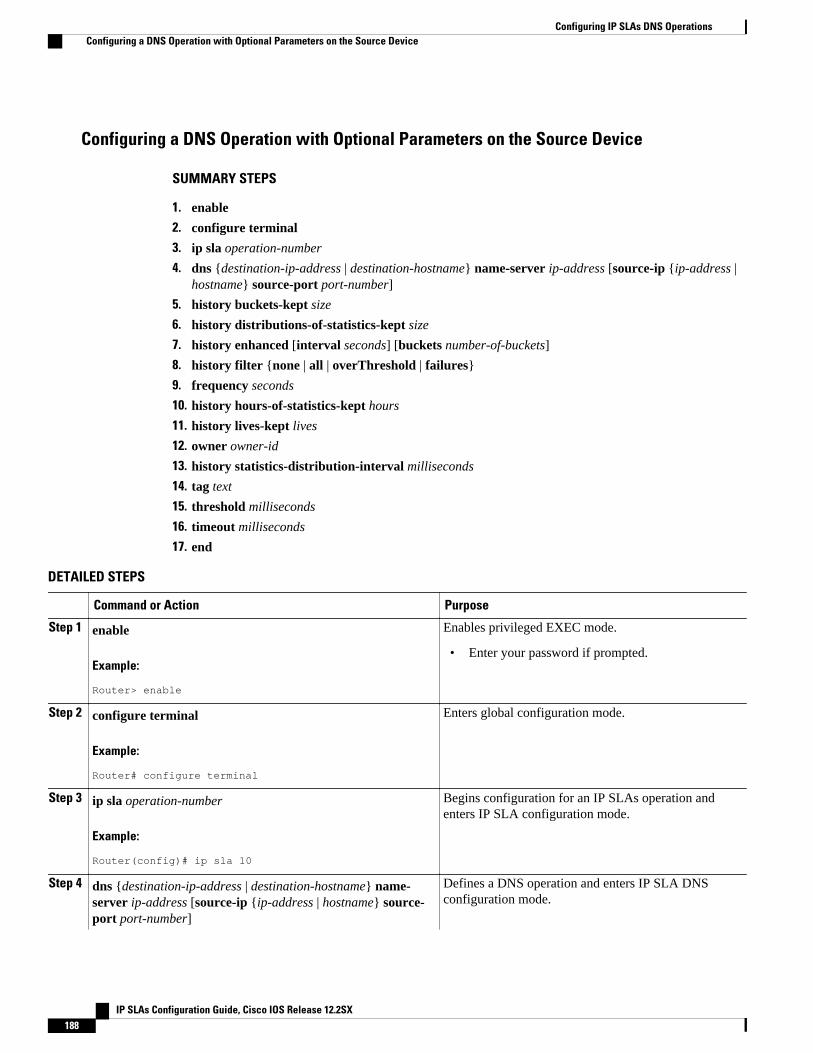
Configuring a DNS Operation with Optional Parameters on the Source Device
SUMMARY STEPS
1. enable
2. configure terminal
3. ip sla operation-number
4. dns {destination-ip-address | destination-hostname} name-server ip-address [source-ip {ip-address |hostname} source-port port-number]
5. history buckets-kept size
6. history distributions-of-statistics-kept size
7. history enhanced [interval seconds] [buckets number-of-buckets]
8. history filter {none | all | overThreshold | failures}
9. frequency seconds
10. history hours-of-statistics-kept hours
11. history lives-kept lives
12. owner owner-id
13. history statistics-distribution-interval milliseconds
14. tag text
15. threshold milliseconds
16. timeout milliseconds
17. end
DETAILED STEPS
Command or Action Purpose
Step 1 enable
Example:
Router> enable
Enables privileged EXEC mode.
• Enter your password if prompted.
Step 2 configure terminal
Example:
Router# configure terminal
Enters global configuration mode.
Step 3 ip sla operation-number
Example:
Router(config)# ip sla 10
Begins configuration for an IP SLAs operation andenters IP SLA configuration mode.
Step 4 dns {destination-ip-address | destination-hostname} name-server ip-address [source-ip {ip-address | hostname} source-port port-number]
Defines a DNS operation and enters IP SLA DNSconfiguration mode.
Configuring IP SLAs DNS Operations Configuring a DNS Operation with Optional Parameters on the Source Device
IP SLAs Configuration Guide, Cisco IOS Release 12.2SX188
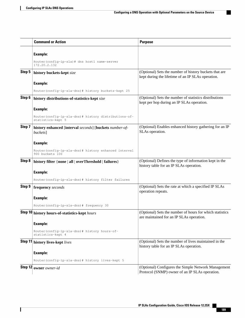
Command or Action Purpose
Example:
Router(config-ip-sla)# dns host1 name-server 172.20.2.132
Step 5 history buckets-kept size
Example:
Router(config-ip-sla-dns)# history buckets-kept 25
(Optional) Sets the number of history buckets that arekept during the lifetime of an IP SLAs operation.
Step 6 history distributions-of-statistics-kept size
Example:
Router(config-ip-sla-dns)# history distributions-of-statistics-kept 5
(Optional) Sets the number of statistics distributionskept per hop during an IP SLAs operation.
Step 7 history enhanced [interval seconds] [buckets number-of-buckets]
Example:
Router(config-ip-sla-dns)# history enhanced interval 900 buckets 100
(Optional) Enables enhanced history gathering for an IPSLAs operation.
Step 8 history filter {none | all | overThreshold | failures}
Example:
Router(config-ip-sla-dns)# history filter failures
(Optional) Defines the type of information kept in thehistory table for an IP SLAs operation.
Step 9 frequency seconds
Example:
Router(config-ip-sla-dns)# frequency 30
(Optional) Sets the rate at which a specified IP SLAsoperation repeats.
Step 10 history hours-of-statistics-kept hours
Example:
Router(config-ip-sla-dns)# history hours-of-statistics-kept 4
(Optional) Sets the number of hours for which statisticsare maintained for an IP SLAs operation.
Step 11 history lives-kept lives
Example:
Router(config-ip-sla-dns)# history lives-kept 5
(Optional) Sets the number of lives maintained in thehistory table for an IP SLAs operation.
Step 12 owner owner-id (Optional) Configures the Simple Network ManagementProtocol (SNMP) owner of an IP SLAs operation.
Configuring IP SLAs DNS OperationsConfiguring a DNS Operation with Optional Parameters on the Source Device
IP SLAs Configuration Guide, Cisco IOS Release 12.2SX 189
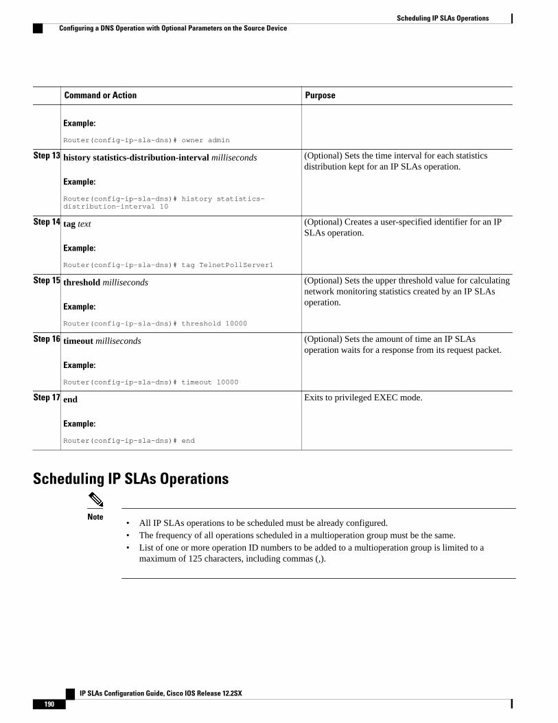
Command or Action Purpose
Example:
Router(config-ip-sla-dns)# owner admin
Step 13 history statistics-distribution-interval milliseconds
Example:
Router(config-ip-sla-dns)# history statistics-distribution-interval 10
(Optional) Sets the time interval for each statisticsdistribution kept for an IP SLAs operation.
Step 14 tag text
Example:
Router(config-ip-sla-dns)# tag TelnetPollServer1
(Optional) Creates a user-specified identifier for an IPSLAs operation.
Step 15 threshold milliseconds
Example:
Router(config-ip-sla-dns)# threshold 10000
(Optional) Sets the upper threshold value for calculatingnetwork monitoring statistics created by an IP SLAsoperation.
Step 16 timeout milliseconds
Example:
Router(config-ip-sla-dns)# timeout 10000
(Optional) Sets the amount of time an IP SLAsoperation waits for a response from its request packet.
Step 17 end
Example:
Router(config-ip-sla-dns)# end
Exits to privileged EXEC mode.
Scheduling IP SLAs Operations
Note• All IP SLAs operations to be scheduled must be already configured.• The frequency of all operations scheduled in a multioperation group must be the same.• List of one or more operation ID numbers to be added to a multioperation group is limited to a
maximum of 125 characters, including commas (,).
Scheduling IP SLAs Operations Configuring a DNS Operation with Optional Parameters on the Source Device
IP SLAs Configuration Guide, Cisco IOS Release 12.2SX190

SUMMARY STEPS
1. enable
2. configure terminal
3. Do one of the following:
• ip sla schedule operation-number [life {forever | seconds}] [start-time {hh : mm[: ss] [month day| day month] | pending | now | after hh : mm : ss}] [ageout seconds] [recurring]
• ip sla group schedule group-operation-number operation-id-numbers schedule-period schedule-period-range [ageout seconds] [frequency group-operation-frequency] [life{forever | seconds}][start-time{hh:mm[:ss] [month day | day month] | pending | now | after hh:mm:ss}]
4. exit
5. show ip sla group schedule
6. show ip sla configuration
DETAILED STEPS
Command or Action Purpose
Step 1 enable
Example:
Router> enable
Enables privileged EXEC mode.
• Enter your password if prompted.
Step 2 configure terminal
Example:
Router# configure terminal
Enters global configuration mode.
Step 3 Do one of the following:
• ip sla schedule operation-number [life {forever | seconds}] [start-time{hh : mm[: ss] [month day | day month] | pending | now | after hh : mm: ss}] [ageout seconds] [recurring]
• ip sla group schedule group-operation-number operation-id-numbersschedule-period schedule-period-range [ageout seconds] [frequencygroup-operation-frequency] [life{forever | seconds}] [start-time{hh:mm[:ss] [month day | day month] | pending | now | afterhh:mm:ss}]
Example:
Router(config)# ip sla schedule 10 start-time now life forever
Example:
Router(config)# ip sla group schedule 1 3,4,6-9
For individual IP SLAs operations only:
Configures the scheduling parameters for anindividual IP SLAs operation.
or
For multioperation scheduler only:
Specifies an IP SLAs operation groupnumber and the range of operation numbersto be scheduled in global configurationmode.
Step 4 exit Exits to privileged EXEC mode.
Configuring IP SLAs DNS OperationsConfiguring a DNS Operation with Optional Parameters on the Source Device
IP SLAs Configuration Guide, Cisco IOS Release 12.2SX 191
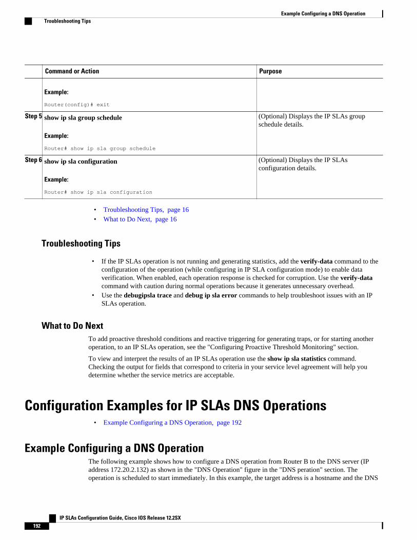
Command or Action Purpose
Example:
Router(config)# exit
Step 5 show ip sla group schedule
Example:
Router# show ip sla group schedule
(Optional) Displays the IP SLAs groupschedule details.
Step 6 show ip sla configuration
Example:
Router# show ip sla configuration
(Optional) Displays the IP SLAsconfiguration details.
• Troubleshooting Tips, page 16• What to Do Next, page 16
Troubleshooting Tips
• If the IP SLAs operation is not running and generating statistics, add the verify-data command to theconfiguration of the operation (while configuring in IP SLA configuration mode) to enable dataverification. When enabled, each operation response is checked for corruption. Use the verify-datacommand with caution during normal operations because it generates unnecessary overhead.
• Use the debugipsla trace and debug ip sla error commands to help troubleshoot issues with an IPSLAs operation.
What to Do NextTo add proactive threshold conditions and reactive triggering for generating traps, or for starting anotheroperation, to an IP SLAs operation, see the "Configuring Proactive Threshold Monitoring" section.
To view and interpret the results of an IP SLAs operation use the show ip sla statistics command.Checking the output for fields that correspond to criteria in your service level agreement will help youdetermine whether the service metrics are acceptable.
Configuration Examples for IP SLAs DNS Operations• Example Configuring a DNS Operation, page 192
Example Configuring a DNS OperationThe following example shows how to configure a DNS operation from Router B to the DNS server (IPaddress 172.20.2.132) as shown in the "DNS Operation" figure in the "DNS peration" section. Theoperation is scheduled to start immediately. In this example, the target address is a hostname and the DNS
Example Configuring a DNS Operation Troubleshooting Tips
IP SLAs Configuration Guide, Cisco IOS Release 12.2SX192
operation will query the DNS server for the IP address associated with the hostname host1. Noconfiguration is required at the DNS server.
Router B Configuration
ip sla 11 dns host1 name-server 172.20.2.132 frequency 50 timeout 8000 tag DNS-Testip sla schedule 11 start-time now
Additional ReferencesRelated Documents
Related Topic Document Title
Cisco IOS commands Cisco IOS Master Commands List, All Releases
Cisco IOS IP SLAs commands Cisco IOS IP SLAs Command Reference
Cisco IOS IP SLAs: general information Configuring IOS IP SLAs Overview chapter of theCisco IOS IP SLAs Configuration Guide
Standards
Standards Title
No new or modified standards are supported by thisfeature, and support for existing standards has notbeen modified by this feature.
--
MIBs
MIBs MIBs Link
CISCO-RTTMON-MIB To locate and download MIBs for selectedplatforms, Cisco IOS releases, and feature sets, useCisco MIB Locator found at the following URL:
http://www.cisco.com/go/mibs
RFCs
RFCs Title
No new or modified RFCs are supported by thisfeature, and support for existing RFCs has not beenmodified by this feature.
--
Configuring IP SLAs DNS OperationsAdditional References
IP SLAs Configuration Guide, Cisco IOS Release 12.2SX 193
Technical Assistance
Description Link
The Cisco Support and Documentation websiteprovides online resources to downloaddocumentation, software, and tools. Use theseresources to install and configure the software andto troubleshoot and resolve technical issues withCisco products and technologies. Access to mosttools on the Cisco Support and Documentationwebsite requires a Cisco.com user ID andpassword.
http://www.cisco.com/cisco/web/support/index.html
Feature Information for IP SLAs DNS OperationsThe following table provides release information about the feature or features described in this module.This table lists only the software release that introduced support for a given feature in a given softwarerelease train. Unless noted otherwise, subsequent releases of that software release train also support thatfeature.
Use Cisco Feature Navigator to find information about platform support and Cisco software image support.To access Cisco Feature Navigator, go to www.cisco.com/go/cfn. An account on Cisco.com is not required.
Table 21: Feature Information for the IP SLAs DNS Operation
Feature Name Releases Feature Information
IP SLAs DNS Operation 12.2(31)SB2 12.2(33)SRB112.2(33)SXH 12.3(14)T 15.0(1)SCisco IOS XE 3.1.0SG
The Cisco IOS IP SLAs DomainName System (DNS) operationallows you to measure thedifference between the time takento send a DNS request andreceive a reply.
Cisco and the Cisco Logo are trademarks of Cisco Systems, Inc. and/or its affiliates in the U.S. and othercountries. A listing of Cisco's trademarks can be found at www.cisco.com/go/trademarks. Third partytrademarks mentioned are the property of their respective owners. The use of the word partner does notimply a partnership relationship between Cisco and any other company. (1005R)
Any Internet Protocol (IP) addresses and phone numbers used in this document are not intended to beactual addresses and phone numbers. Any examples, command display output, network topology diagrams,and other figures included in the document are shown for illustrative purposes only. Any use of actual IPaddresses or phone numbers in illustrative content is unintentional and coincidental.
Configuring IP SLAs DNS Operations Feature Information for IP SLAs DNS Operations
IP SLAs Configuration Guide, Cisco IOS Release 12.2SX194
Configuring IP SLAs DHCP Operations
This module describes how to configure an IP Service Level Agreements (SLAs) Dynamic Host ControlProtocol (DHCP) operation to measure the response time between a Cisco device and a DHCP server toobtain an IP address.
• Finding Feature Information, page 195• Information About IP SLAs DHCP Operations, page 195• How to Configure IP SLAs DHCP Operations, page 196• Configuration Examples for IP SLAs DHCP Operations, page 202• Additional References, page 203• Feature Information for IP SLAs DHCP Operations, page 204
Finding Feature InformationYour software release may not support all the features documented in this module. For the latest featureinformation and caveats, see the release notes for your platform and software release. To find informationabout the features documented in this module, and to see a list of the releases in which each feature issupported, see the Feature Information Table at the end of this document.
Use Cisco Feature Navigator to find information about platform support and Cisco software image support.To access Cisco Feature Navigator, go to www.cisco.com/go/cfn. An account on Cisco.com is not required.
Information About IP SLAs DHCP Operations• DHCP Operation, page 195
• IP SLAs DHCP Relay Agent Options, page 196
DHCP OperationDHCP provides a mechanism for allocating IP addresses dynamically so that addresses can be reused whenhosts no longer need them. The DHCP operation measures the round-trip time (RTT) taken to discover aDHCP server and obtain a leased IP address from it. IP SLAs releases the leased IP address after theoperation.
You can use the RTT information to determine DHCP performance levels.
IP SLAs Configuration Guide, Cisco IOS Release 12.2SX 195
There are two modes for the DHCP operation. By default, the DHCP operation sends discovery packets onevery available IP interface on the router. If a specific server is configured on the router, discovery packetsare sent only to the specified DHCP server.
IP SLAs DHCP Relay Agent OptionsA DHCP relay agent is any host that forwards DHCP packets between clients and servers. Relay agents areused to forward requests and replies between clients and servers when they are not on the same physicalsubnet. Relay agent forwarding is distinct from the normal forwarding of an IP router, where IP packets areswitched between networks somewhat transparently. Relay agents receive DHCP messages and thengenerate a new DHCP message to send out on another interface.
The IP SLAs DHCP operation contains a relay agent information option--Option 82--which is inserted bythe DHCP relay agent when forwarding client-originated DHCP packets to a DHCP server. Serversrecognizing the relay agent information option may use the information to implement IP address or otherparameter assignment policies. The DHCP server echoes the option back verbatim to the relay agent inserver-to-client replies, and the relay agent strips the option before forwarding the reply to the client.
Option 82 includes three suboptions that convey information known by the relay agent:
• circuit-id --identifies the incoming circuit.• remote-id --provides a trusted identifier for a remote high-speed modem.• subnet-mask --identifies the mask of the logical IP subnet from which the relay agent received the
client DHCP packet.
How to Configure IP SLAs DHCP Operations
Note There is no need to configure an IP SLAs responder on the destination device.
• Configuring a DHCP Operation on the Source Device, page 196
• Scheduling IP SLAs Operations, page 104
Configuring a DHCP Operation on the Source DevicePerform one of the following tasks:
• Configuring a Basic DHCP Operation, page 196
• Configuring a DHCP Operation with Optional Parameters, page 198
Configuring a Basic DHCP Operation
IP SLAs DHCP Relay Agent Options How to Configure IP SLAs DHCP Operations
IP SLAs Configuration Guide, Cisco IOS Release 12.2SX196
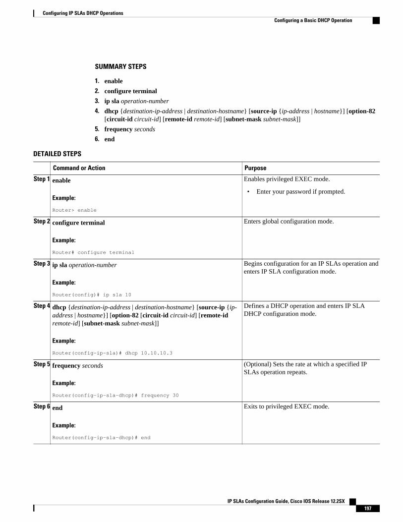
SUMMARY STEPS
1. enable
2. configure terminal
3. ip sla operation-number
4. dhcp {destination-ip-address | destination-hostname} [source-ip {ip-address | hostname}] [option-82[circuit-id circuit-id] [remote-id remote-id] [subnet-mask subnet-mask]]
5. frequency seconds
6. end
DETAILED STEPS
Command or Action Purpose
Step 1 enable
Example:
Router> enable
Enables privileged EXEC mode.
• Enter your password if prompted.
Step 2 configure terminal
Example:
Router# configure terminal
Enters global configuration mode.
Step 3 ip sla operation-number
Example:
Router(config)# ip sla 10
Begins configuration for an IP SLAs operation andenters IP SLA configuration mode.
Step 4 dhcp {destination-ip-address | destination-hostname} [source-ip {ip-address | hostname}] [option-82 [circuit-id circuit-id] [remote-idremote-id] [subnet-mask subnet-mask]]
Example:
Router(config-ip-sla)# dhcp 10.10.10.3
Defines a DHCP operation and enters IP SLADHCP configuration mode.
Step 5 frequency seconds
Example:
Router(config-ip-sla-dhcp)# frequency 30
(Optional) Sets the rate at which a specified IPSLAs operation repeats.
Step 6 end
Example:
Router(config-ip-sla-dhcp)# end
Exits to privileged EXEC mode.
Configuring IP SLAs DHCP OperationsConfiguring a Basic DHCP Operation
IP SLAs Configuration Guide, Cisco IOS Release 12.2SX 197
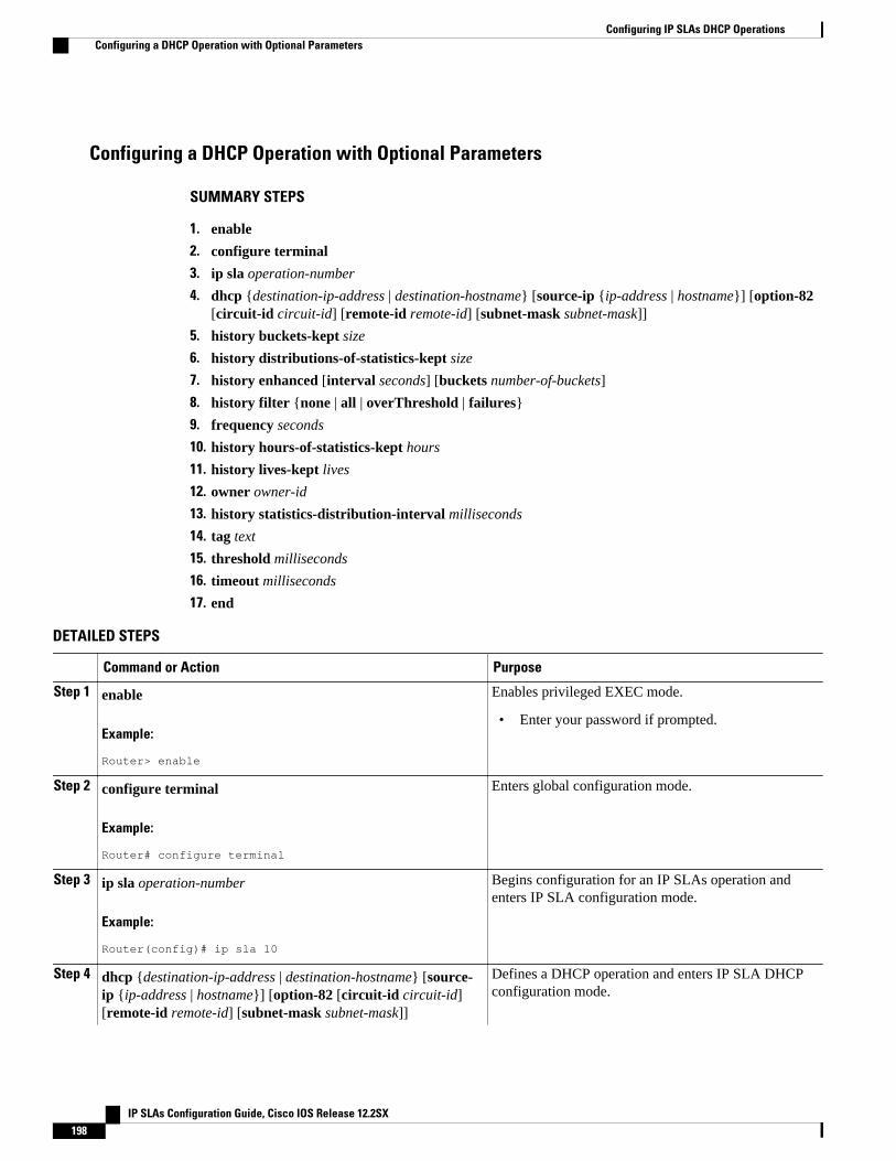
Configuring a DHCP Operation with Optional Parameters
SUMMARY STEPS
1. enable
2. configure terminal
3. ip sla operation-number
4. dhcp {destination-ip-address | destination-hostname} [source-ip {ip-address | hostname}] [option-82[circuit-id circuit-id] [remote-id remote-id] [subnet-mask subnet-mask]]
5. history buckets-kept size
6. history distributions-of-statistics-kept size
7. history enhanced [interval seconds] [buckets number-of-buckets]
8. history filter {none | all | overThreshold | failures}
9. frequency seconds
10. history hours-of-statistics-kept hours
11. history lives-kept lives
12. owner owner-id
13. history statistics-distribution-interval milliseconds
14. tag text
15. threshold milliseconds
16. timeout milliseconds
17. end
DETAILED STEPS
Command or Action Purpose
Step 1 enable
Example:
Router> enable
Enables privileged EXEC mode.
• Enter your password if prompted.
Step 2 configure terminal
Example:
Router# configure terminal
Enters global configuration mode.
Step 3 ip sla operation-number
Example:
Router(config)# ip sla 10
Begins configuration for an IP SLAs operation andenters IP SLA configuration mode.
Step 4 dhcp {destination-ip-address | destination-hostname} [source-ip {ip-address | hostname}] [option-82 [circuit-id circuit-id][remote-id remote-id] [subnet-mask subnet-mask]]
Defines a DHCP operation and enters IP SLA DHCPconfiguration mode.
Configuring IP SLAs DHCP Operations Configuring a DHCP Operation with Optional Parameters
IP SLAs Configuration Guide, Cisco IOS Release 12.2SX198
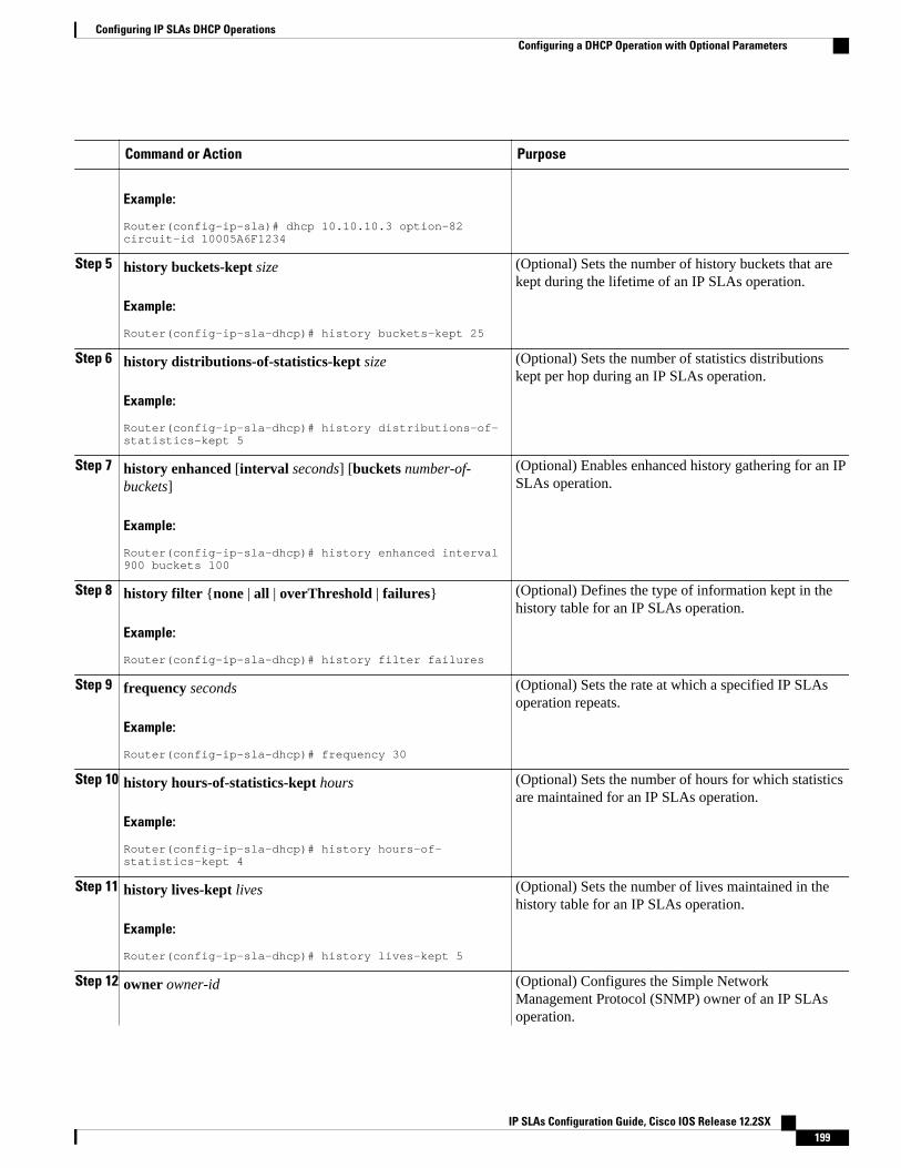
Command or Action Purpose
Example:
Router(config-ip-sla)# dhcp 10.10.10.3 option-82 circuit-id 10005A6F1234
Step 5 history buckets-kept size
Example:
Router(config-ip-sla-dhcp)# history buckets-kept 25
(Optional) Sets the number of history buckets that arekept during the lifetime of an IP SLAs operation.
Step 6 history distributions-of-statistics-kept size
Example:
Router(config-ip-sla-dhcp)# history distributions-of-statistics-kept 5
(Optional) Sets the number of statistics distributionskept per hop during an IP SLAs operation.
Step 7 history enhanced [interval seconds] [buckets number-of-buckets]
Example:
Router(config-ip-sla-dhcp)# history enhanced interval 900 buckets 100
(Optional) Enables enhanced history gathering for an IPSLAs operation.
Step 8 history filter {none | all | overThreshold | failures}
Example:
Router(config-ip-sla-dhcp)# history filter failures
(Optional) Defines the type of information kept in thehistory table for an IP SLAs operation.
Step 9 frequency seconds
Example:
Router(config-ip-sla-dhcp)# frequency 30
(Optional) Sets the rate at which a specified IP SLAsoperation repeats.
Step 10 history hours-of-statistics-kept hours
Example:
Router(config-ip-sla-dhcp)# history hours-of-statistics-kept 4
(Optional) Sets the number of hours for which statisticsare maintained for an IP SLAs operation.
Step 11 history lives-kept lives
Example:
Router(config-ip-sla-dhcp)# history lives-kept 5
(Optional) Sets the number of lives maintained in thehistory table for an IP SLAs operation.
Step 12 owner owner-id (Optional) Configures the Simple NetworkManagement Protocol (SNMP) owner of an IP SLAsoperation.
Configuring IP SLAs DHCP OperationsConfiguring a DHCP Operation with Optional Parameters
IP SLAs Configuration Guide, Cisco IOS Release 12.2SX 199
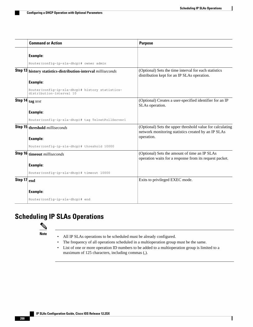
Command or Action Purpose
Example:
Router(config-ip-sla-dhcp)# owner admin
Step 13 history statistics-distribution-interval milliseconds
Example:
Router(config-ip-sla-dhcp)# history statistics-distribution-interval 10
(Optional) Sets the time interval for each statisticsdistribution kept for an IP SLAs operation.
Step 14 tag text
Example:
Router(config-ip-sla-dhcp)# tag TelnetPollServer1
(Optional) Creates a user-specified identifier for an IPSLAs operation.
Step 15 threshold milliseconds
Example:
Router(config-ip-sla-dhcp)# threshold 10000
(Optional) Sets the upper threshold value for calculatingnetwork monitoring statistics created by an IP SLAsoperation.
Step 16 timeout milliseconds
Example:
Router(config-ip-sla-dhcp)# timeout 10000
(Optional) Sets the amount of time an IP SLAsoperation waits for a response from its request packet.
Step 17 end
Example:
Router(config-ip-sla-dhcp)# end
Exits to privileged EXEC mode.
Scheduling IP SLAs Operations
Note• All IP SLAs operations to be scheduled must be already configured.• The frequency of all operations scheduled in a multioperation group must be the same.• List of one or more operation ID numbers to be added to a multioperation group is limited to a
maximum of 125 characters, including commas (,).
Scheduling IP SLAs Operations Configuring a DHCP Operation with Optional Parameters
IP SLAs Configuration Guide, Cisco IOS Release 12.2SX200
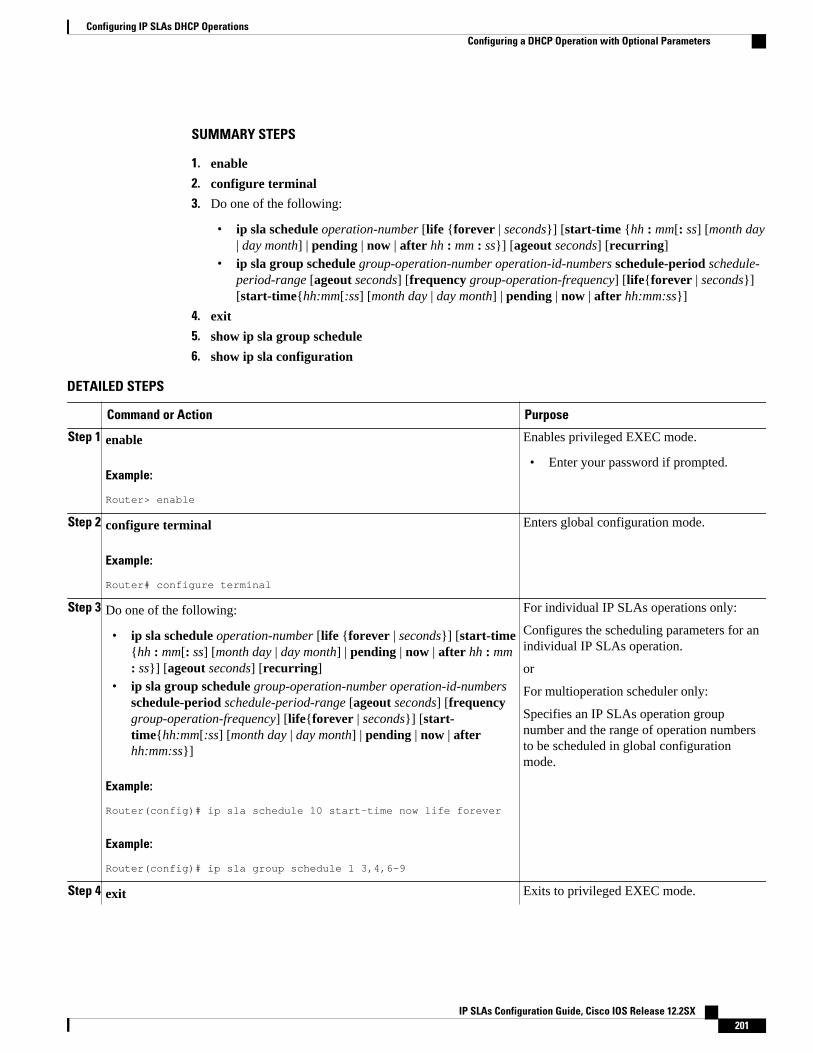
SUMMARY STEPS
1. enable
2. configure terminal
3. Do one of the following:
• ip sla schedule operation-number [life {forever | seconds}] [start-time {hh : mm[: ss] [month day| day month] | pending | now | after hh : mm : ss}] [ageout seconds] [recurring]
• ip sla group schedule group-operation-number operation-id-numbers schedule-period schedule-period-range [ageout seconds] [frequency group-operation-frequency] [life{forever | seconds}][start-time{hh:mm[:ss] [month day | day month] | pending | now | after hh:mm:ss}]
4. exit
5. show ip sla group schedule
6. show ip sla configuration
DETAILED STEPS
Command or Action Purpose
Step 1 enable
Example:
Router> enable
Enables privileged EXEC mode.
• Enter your password if prompted.
Step 2 configure terminal
Example:
Router# configure terminal
Enters global configuration mode.
Step 3 Do one of the following:
• ip sla schedule operation-number [life {forever | seconds}] [start-time{hh : mm[: ss] [month day | day month] | pending | now | after hh : mm: ss}] [ageout seconds] [recurring]
• ip sla group schedule group-operation-number operation-id-numbersschedule-period schedule-period-range [ageout seconds] [frequencygroup-operation-frequency] [life{forever | seconds}] [start-time{hh:mm[:ss] [month day | day month] | pending | now | afterhh:mm:ss}]
Example:
Router(config)# ip sla schedule 10 start-time now life forever
Example:
Router(config)# ip sla group schedule 1 3,4,6-9
For individual IP SLAs operations only:
Configures the scheduling parameters for anindividual IP SLAs operation.
or
For multioperation scheduler only:
Specifies an IP SLAs operation groupnumber and the range of operation numbersto be scheduled in global configurationmode.
Step 4 exit Exits to privileged EXEC mode.
Configuring IP SLAs DHCP OperationsConfiguring a DHCP Operation with Optional Parameters
IP SLAs Configuration Guide, Cisco IOS Release 12.2SX 201
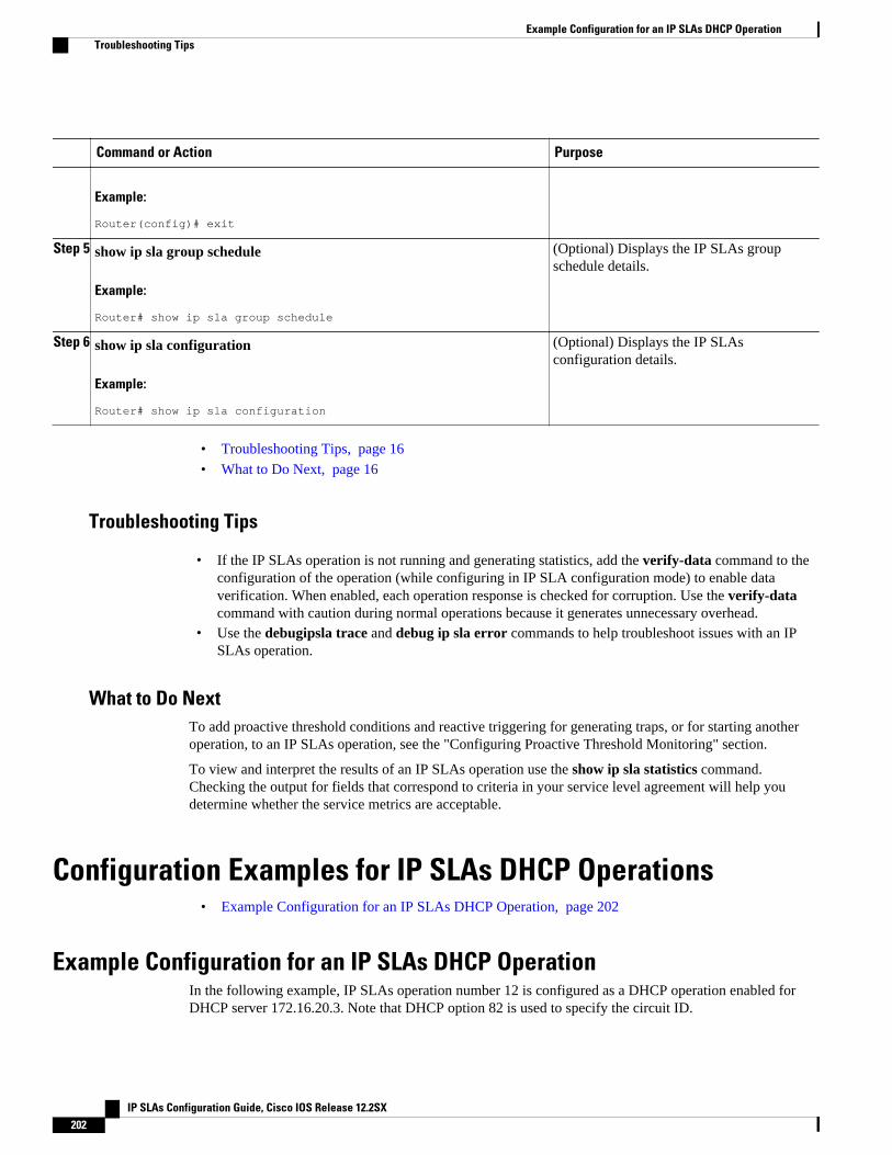
Command or Action Purpose
Example:
Router(config)# exit
Step 5 show ip sla group schedule
Example:
Router# show ip sla group schedule
(Optional) Displays the IP SLAs groupschedule details.
Step 6 show ip sla configuration
Example:
Router# show ip sla configuration
(Optional) Displays the IP SLAsconfiguration details.
• Troubleshooting Tips, page 16
• What to Do Next, page 16
Troubleshooting Tips
• If the IP SLAs operation is not running and generating statistics, add the verify-data command to theconfiguration of the operation (while configuring in IP SLA configuration mode) to enable dataverification. When enabled, each operation response is checked for corruption. Use the verify-datacommand with caution during normal operations because it generates unnecessary overhead.
• Use the debugipsla trace and debug ip sla error commands to help troubleshoot issues with an IPSLAs operation.
What to Do NextTo add proactive threshold conditions and reactive triggering for generating traps, or for starting anotheroperation, to an IP SLAs operation, see the "Configuring Proactive Threshold Monitoring" section.
To view and interpret the results of an IP SLAs operation use the show ip sla statistics command.Checking the output for fields that correspond to criteria in your service level agreement will help youdetermine whether the service metrics are acceptable.
Configuration Examples for IP SLAs DHCP Operations• Example Configuration for an IP SLAs DHCP Operation, page 202
Example Configuration for an IP SLAs DHCP OperationIn the following example, IP SLAs operation number 12 is configured as a DHCP operation enabled forDHCP server 172.16.20.3. Note that DHCP option 82 is used to specify the circuit ID.
Example Configuration for an IP SLAs DHCP Operation Troubleshooting Tips
IP SLAs Configuration Guide, Cisco IOS Release 12.2SX202
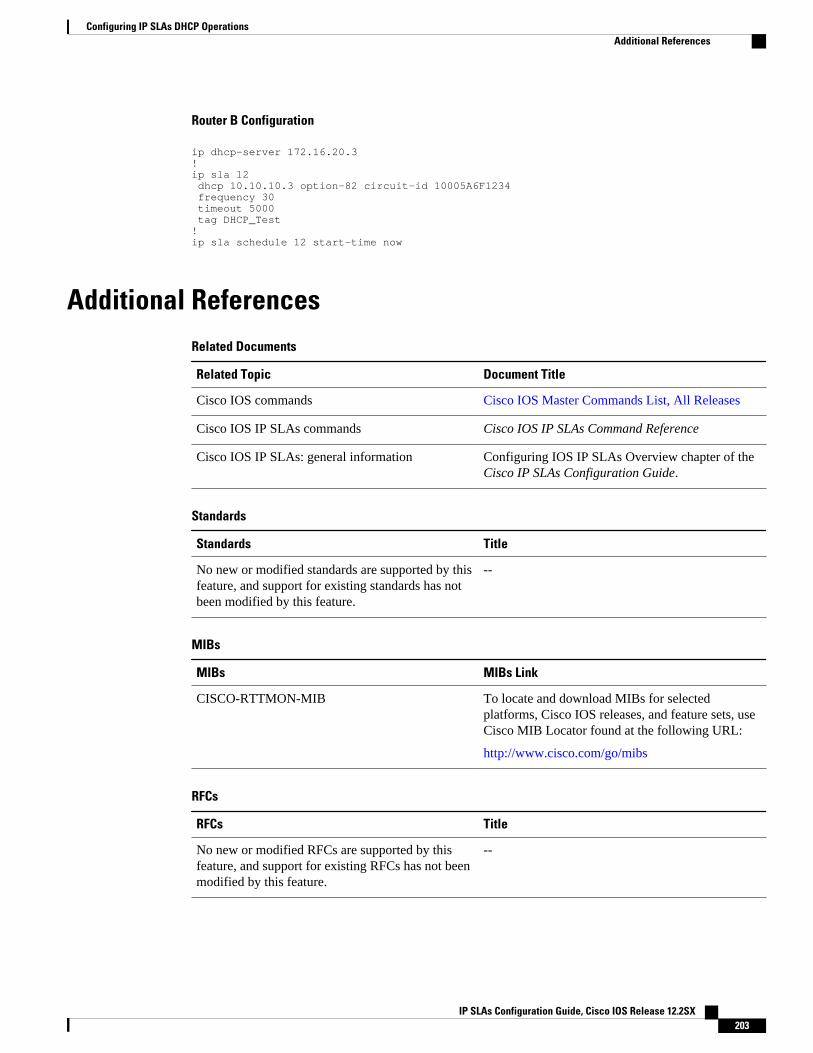
Router B Configuration
ip dhcp-server 172.16.20.3!ip sla 12 dhcp 10.10.10.3 option-82 circuit-id 10005A6F1234 frequency 30 timeout 5000 tag DHCP_Test!ip sla schedule 12 start-time now
Additional ReferencesRelated Documents
Related Topic Document Title
Cisco IOS commands Cisco IOS Master Commands List, All Releases
Cisco IOS IP SLAs commands Cisco IOS IP SLAs Command Reference
Cisco IOS IP SLAs: general information Configuring IOS IP SLAs Overview chapter of theCisco IP SLAs Configuration Guide.
Standards
Standards Title
No new or modified standards are supported by thisfeature, and support for existing standards has notbeen modified by this feature.
--
MIBs
MIBs MIBs Link
CISCO-RTTMON-MIB To locate and download MIBs for selectedplatforms, Cisco IOS releases, and feature sets, useCisco MIB Locator found at the following URL:
http://www.cisco.com/go/mibs
RFCs
RFCs Title
No new or modified RFCs are supported by thisfeature, and support for existing RFCs has not beenmodified by this feature.
--
Configuring IP SLAs DHCP OperationsAdditional References
IP SLAs Configuration Guide, Cisco IOS Release 12.2SX 203
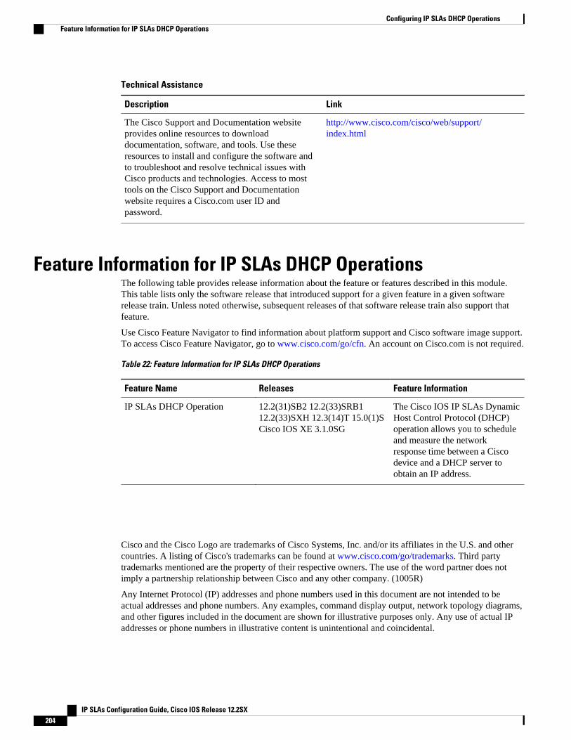
Technical Assistance
Description Link
The Cisco Support and Documentation websiteprovides online resources to downloaddocumentation, software, and tools. Use theseresources to install and configure the software andto troubleshoot and resolve technical issues withCisco products and technologies. Access to mosttools on the Cisco Support and Documentationwebsite requires a Cisco.com user ID andpassword.
http://www.cisco.com/cisco/web/support/index.html
Feature Information for IP SLAs DHCP OperationsThe following table provides release information about the feature or features described in this module.This table lists only the software release that introduced support for a given feature in a given softwarerelease train. Unless noted otherwise, subsequent releases of that software release train also support thatfeature.
Use Cisco Feature Navigator to find information about platform support and Cisco software image support.To access Cisco Feature Navigator, go to www.cisco.com/go/cfn. An account on Cisco.com is not required.
Table 22: Feature Information for IP SLAs DHCP Operations
Feature Name Releases Feature Information
IP SLAs DHCP Operation 12.2(31)SB2 12.2(33)SRB112.2(33)SXH 12.3(14)T 15.0(1)SCisco IOS XE 3.1.0SG
The Cisco IOS IP SLAs DynamicHost Control Protocol (DHCP)operation allows you to scheduleand measure the networkresponse time between a Ciscodevice and a DHCP server toobtain an IP address.
Cisco and the Cisco Logo are trademarks of Cisco Systems, Inc. and/or its affiliates in the U.S. and othercountries. A listing of Cisco's trademarks can be found at www.cisco.com/go/trademarks. Third partytrademarks mentioned are the property of their respective owners. The use of the word partner does notimply a partnership relationship between Cisco and any other company. (1005R)
Any Internet Protocol (IP) addresses and phone numbers used in this document are not intended to beactual addresses and phone numbers. Any examples, command display output, network topology diagrams,and other figures included in the document are shown for illustrative purposes only. Any use of actual IPaddresses or phone numbers in illustrative content is unintentional and coincidental.
Configuring IP SLAs DHCP Operations Feature Information for IP SLAs DHCP Operations
IP SLAs Configuration Guide, Cisco IOS Release 12.2SX204
Configuring IP SLAs DLSw+ Operations
This module describes how to configure the IP Service Level Agreements (SLAs) Data Link SwitchingPlus (DLSw+) operation to measure and analyze the DLSw+ protocol stack and network response timebetween DLSw+ peers.
• Finding Feature Information, page 205• Prerequisites, page 205• Information About IP SLAs DLSw+ Operations, page 205• How to Configure IP SLAs DLSw+ Operations, page 206• Configuration Examples for IP SLAs DLSw+ Operations, page 212• Additional References, page 213• Feature Information for Cisco IOS IP SLAs DLSw+ Operations, page 214
Finding Feature InformationYour software release may not support all the features documented in this module. For the latest featureinformation and caveats, see the release notes for your platform and software release. To find informationabout the features documented in this module, and to see a list of the releases in which each feature issupported, see the Feature Information Table at the end of this document.
Use Cisco Feature Navigator to find information about platform support and Cisco software image support.To access Cisco Feature Navigator, go to www.cisco.com/go/cfn. An account on Cisco.com is not required.
PrerequisitesA connected DLSw+ peer between the source and destination networking devices must be configured.
Information About IP SLAs DLSw+ Operations• DLSw+ Operation, page 205
DLSw+ OperationThe Cisco IOS IP SLAs DLSw+ operation measures the DLSw+ protocol stack and network response timebetween DLSw+ peers. DLSw+ is the enhanced Cisco version of RFC 1795. DLSw+ tunnels non-routable
IP SLAs Configuration Guide, Cisco IOS Release 12.2SX 205
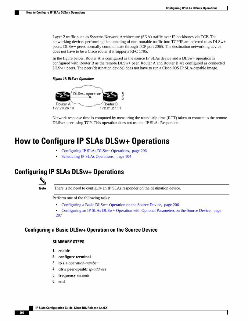
Layer 2 traffic such as Systems Network Architecture (SNA) traffic over IP backbones via TCP. Thenetworking devices performing the tunneling of non-routable traffic into TCP/IP are referred to as DLSw+peers. DLSw+ peers normally communicate through TCP port 2065. The destination networking devicedoes not have to be a Cisco router if it supports RFC 1795.
In the figure below, Router A is configured as the source IP SLAs device and a DLSw+ operation isconfigured with Router B as the remote DLSw+ peer. Router A and Router B are configured as connectedDLSw+ peers. The peer (destination device) does not have to run a Cisco IOS IP SLA-capable image.
Figure 17: DLSw+ Operation
Network response time is computed by measuring the round-trip time (RTT) taken to connect to the remoteDLSw+ peer using TCP. This operation does not use the IP SLAs Responder.
How to Configure IP SLAs DLSw+ Operations• Configuring IP SLAs DLSw+ Operations, page 206
• Scheduling IP SLAs Operations, page 104
Configuring IP SLAs DLSw+ Operations
Note There is no need to configure an IP SLAs responder on the destination device.
Perform one of the following tasks:
• Configuring a Basic DLSw+ Operation on the Source Device, page 206
• Configuring an IP SLAs DLSw+ Operation with Optional Parameters on the Source Device, page207
Configuring a Basic DLSw+ Operation on the Source Device
SUMMARY STEPS
1. enable
2. configure terminal
3. ip sla operation-number
4. dlsw peer-ipaddr ip-address
5. frequency seconds
6. end
Configuring IP SLAs DLSw+ Operations How to Configure IP SLAs DLSw+ Operations
IP SLAs Configuration Guide, Cisco IOS Release 12.2SX206
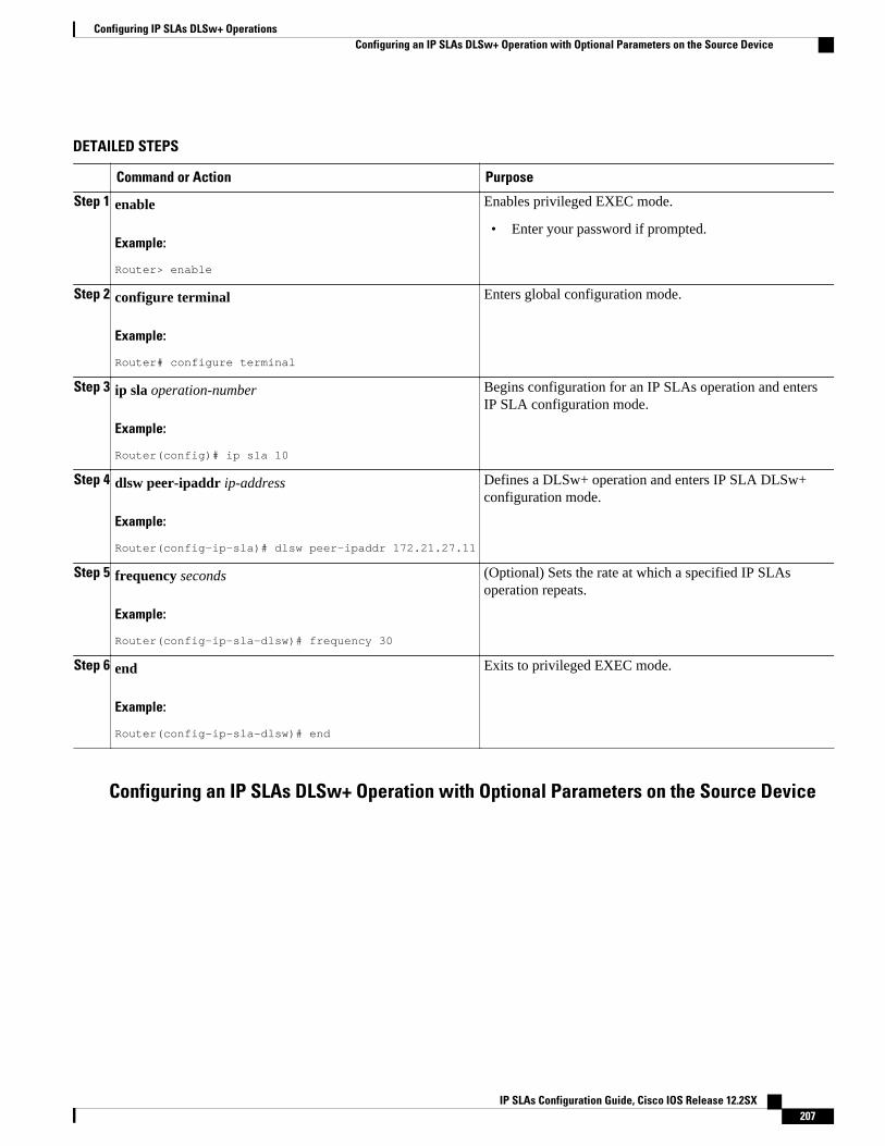
DETAILED STEPS
Command or Action Purpose
Step 1 enable
Example:
Router> enable
Enables privileged EXEC mode.
• Enter your password if prompted.
Step 2 configure terminal
Example:
Router# configure terminal
Enters global configuration mode.
Step 3 ip sla operation-number
Example:
Router(config)# ip sla 10
Begins configuration for an IP SLAs operation and entersIP SLA configuration mode.
Step 4 dlsw peer-ipaddr ip-address
Example:
Router(config-ip-sla)# dlsw peer-ipaddr 172.21.27.11
Defines a DLSw+ operation and enters IP SLA DLSw+configuration mode.
Step 5 frequency seconds
Example:
Router(config-ip-sla-dlsw)# frequency 30
(Optional) Sets the rate at which a specified IP SLAsoperation repeats.
Step 6 end
Example:
Router(config-ip-sla-dlsw)# end
Exits to privileged EXEC mode.
Configuring an IP SLAs DLSw+ Operation with Optional Parameters on the Source Device
Configuring IP SLAs DLSw+ OperationsConfiguring an IP SLAs DLSw+ Operation with Optional Parameters on the Source Device
IP SLAs Configuration Guide, Cisco IOS Release 12.2SX 207
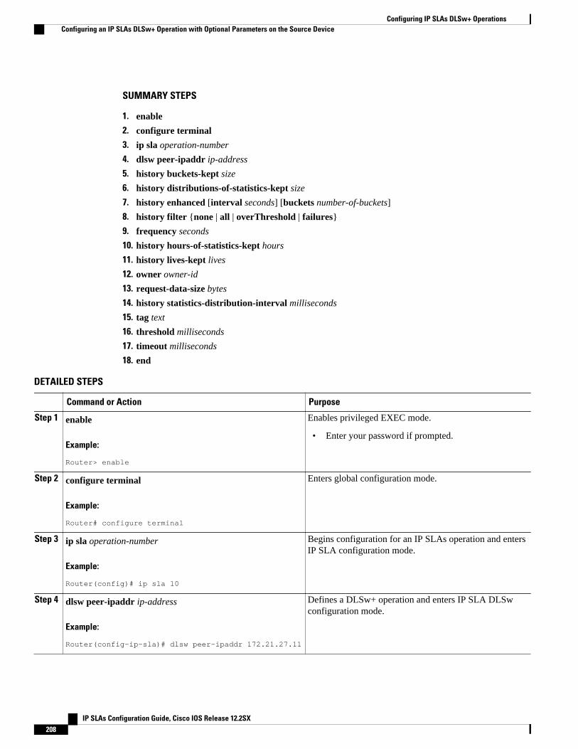
SUMMARY STEPS
1. enable
2. configure terminal
3. ip sla operation-number
4. dlsw peer-ipaddr ip-address
5. history buckets-kept size
6. history distributions-of-statistics-kept size
7. history enhanced [interval seconds] [buckets number-of-buckets]
8. history filter {none | all | overThreshold | failures}
9. frequency seconds
10. history hours-of-statistics-kept hours
11. history lives-kept lives
12. owner owner-id
13. request-data-size bytes
14. history statistics-distribution-interval milliseconds
15. tag text
16. threshold milliseconds
17. timeout milliseconds
18. end
DETAILED STEPS
Command or Action Purpose
Step 1 enable
Example:
Router> enable
Enables privileged EXEC mode.
• Enter your password if prompted.
Step 2 configure terminal
Example:
Router# configure terminal
Enters global configuration mode.
Step 3 ip sla operation-number
Example:
Router(config)# ip sla 10
Begins configuration for an IP SLAs operation and entersIP SLA configuration mode.
Step 4 dlsw peer-ipaddr ip-address
Example:
Router(config-ip-sla)# dlsw peer-ipaddr 172.21.27.11
Defines a DLSw+ operation and enters IP SLA DLSwconfiguration mode.
Configuring IP SLAs DLSw+ Operations Configuring an IP SLAs DLSw+ Operation with Optional Parameters on the Source Device
IP SLAs Configuration Guide, Cisco IOS Release 12.2SX208
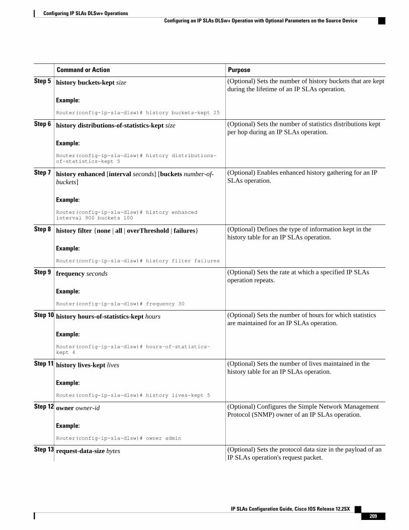
Command or Action Purpose
Step 5 history buckets-kept size
Example:
Router(config-ip-sla-dlsw)# history buckets-kept 25
(Optional) Sets the number of history buckets that are keptduring the lifetime of an IP SLAs operation.
Step 6 history distributions-of-statistics-kept size
Example:
Router(config-ip-sla-dlsw)# history distributions-of-statistics-kept 5
(Optional) Sets the number of statistics distributions keptper hop during an IP SLAs operation.
Step 7 history enhanced [interval seconds] [buckets number-of-buckets]
Example:
Router(config-ip-sla-dlsw)# history enhanced interval 900 buckets 100
(Optional) Enables enhanced history gathering for an IPSLAs operation.
Step 8 history filter {none | all | overThreshold | failures}
Example:
Router(config-ip-sla-dlsw)# history filter failures
(Optional) Defines the type of information kept in thehistory table for an IP SLAs operation.
Step 9 frequency seconds
Example:
Router(config-ip-sla-dlsw)# frequency 30
(Optional) Sets the rate at which a specified IP SLAsoperation repeats.
Step 10 history hours-of-statistics-kept hours
Example:
Router(config-ip-sla-dlsw)# hours-of-statistics-kept 4
(Optional) Sets the number of hours for which statisticsare maintained for an IP SLAs operation.
Step 11 history lives-kept lives
Example:
Router(config-ip-sla-dlsw)# history lives-kept 5
(Optional) Sets the number of lives maintained in thehistory table for an IP SLAs operation.
Step 12 owner owner-id
Example:
Router(config-ip-sla-dlsw)# owner admin
(Optional) Configures the Simple Network ManagementProtocol (SNMP) owner of an IP SLAs operation.
Step 13 request-data-size bytes (Optional) Sets the protocol data size in the payload of anIP SLAs operation's request packet.
Configuring IP SLAs DLSw+ OperationsConfiguring an IP SLAs DLSw+ Operation with Optional Parameters on the Source Device
IP SLAs Configuration Guide, Cisco IOS Release 12.2SX 209
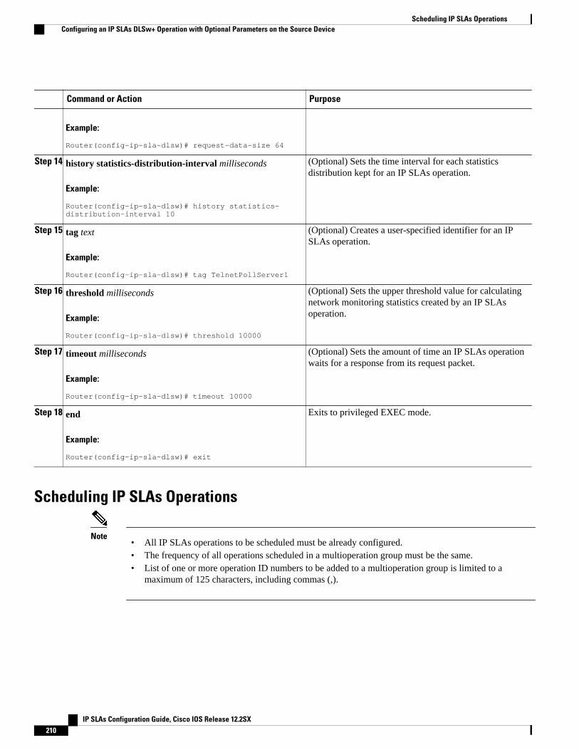
Command or Action Purpose
Example:
Router(config-ip-sla-dlsw)# request-data-size 64
Step 14 history statistics-distribution-interval milliseconds
Example:
Router(config-ip-sla-dlsw)# history statistics-distribution-interval 10
(Optional) Sets the time interval for each statisticsdistribution kept for an IP SLAs operation.
Step 15 tag text
Example:
Router(config-ip-sla-dlsw)# tag TelnetPollServer1
(Optional) Creates a user-specified identifier for an IPSLAs operation.
Step 16 threshold milliseconds
Example:
Router(config-ip-sla-dlsw)# threshold 10000
(Optional) Sets the upper threshold value for calculatingnetwork monitoring statistics created by an IP SLAsoperation.
Step 17 timeout milliseconds
Example:
Router(config-ip-sla-dlsw)# timeout 10000
(Optional) Sets the amount of time an IP SLAs operationwaits for a response from its request packet.
Step 18 end
Example:
Router(config-ip-sla-dlsw)# exit
Exits to privileged EXEC mode.
Scheduling IP SLAs Operations
Note• All IP SLAs operations to be scheduled must be already configured.• The frequency of all operations scheduled in a multioperation group must be the same.• List of one or more operation ID numbers to be added to a multioperation group is limited to a
maximum of 125 characters, including commas (,).
Scheduling IP SLAs Operations Configuring an IP SLAs DLSw+ Operation with Optional Parameters on the Source Device
IP SLAs Configuration Guide, Cisco IOS Release 12.2SX210

SUMMARY STEPS
1. enable
2. configure terminal
3. Do one of the following:
• ip sla schedule operation-number [life {forever | seconds}] [start-time {hh : mm[: ss] [month day| day month] | pending | now | after hh : mm : ss}] [ageout seconds] [recurring]
• ip sla group schedule group-operation-number operation-id-numbers schedule-period schedule-period-range [ageout seconds] [frequency group-operation-frequency] [life{forever | seconds}][start-time{hh:mm[:ss] [month day | day month] | pending | now | after hh:mm:ss}]
4. exit
5. show ip sla group schedule
6. show ip sla configuration
DETAILED STEPS
Command or Action Purpose
Step 1 enable
Example:
Router> enable
Enables privileged EXEC mode.
• Enter your password if prompted.
Step 2 configure terminal
Example:
Router# configure terminal
Enters global configuration mode.
Step 3 Do one of the following:
• ip sla schedule operation-number [life {forever | seconds}] [start-time{hh : mm[: ss] [month day | day month] | pending | now | after hh : mm: ss}] [ageout seconds] [recurring]
• ip sla group schedule group-operation-number operation-id-numbersschedule-period schedule-period-range [ageout seconds] [frequencygroup-operation-frequency] [life{forever | seconds}] [start-time{hh:mm[:ss] [month day | day month] | pending | now | afterhh:mm:ss}]
Example:
Router(config)# ip sla schedule 10 start-time now life forever
Example:
Router(config)# ip sla group schedule 1 3,4,6-9
For individual IP SLAs operations only:
Configures the scheduling parameters for anindividual IP SLAs operation.
or
For multioperation scheduler only:
Specifies an IP SLAs operation groupnumber and the range of operation numbersto be scheduled in global configurationmode.
Step 4 exit Exits to privileged EXEC mode.
Configuring IP SLAs DLSw+ OperationsConfiguring an IP SLAs DLSw+ Operation with Optional Parameters on the Source Device
IP SLAs Configuration Guide, Cisco IOS Release 12.2SX 211
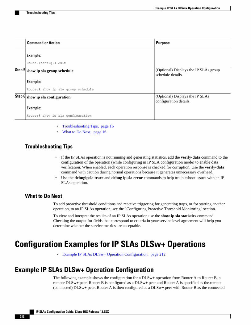
Command or Action Purpose
Example:
Router(config)# exit
Step 5 show ip sla group schedule
Example:
Router# show ip sla group schedule
(Optional) Displays the IP SLAs groupschedule details.
Step 6 show ip sla configuration
Example:
Router# show ip sla configuration
(Optional) Displays the IP SLAsconfiguration details.
• Troubleshooting Tips, page 16• What to Do Next, page 16
Troubleshooting Tips
• If the IP SLAs operation is not running and generating statistics, add the verify-data command to theconfiguration of the operation (while configuring in IP SLA configuration mode) to enable dataverification. When enabled, each operation response is checked for corruption. Use the verify-datacommand with caution during normal operations because it generates unnecessary overhead.
• Use the debugipsla trace and debug ip sla error commands to help troubleshoot issues with an IPSLAs operation.
What to Do NextTo add proactive threshold conditions and reactive triggering for generating traps, or for starting anotheroperation, to an IP SLAs operation, see the "Configuring Proactive Threshold Monitoring" section.
To view and interpret the results of an IP SLAs operation use the show ip sla statistics command.Checking the output for fields that correspond to criteria in your service level agreement will help youdetermine whether the service metrics are acceptable.
Configuration Examples for IP SLAs DLSw+ Operations• Example IP SLAs DLSw+ Operation Configuration, page 212
Example IP SLAs DLSw+ Operation ConfigurationThe following example shows the configuration for a DLSw+ operation from Router A to Router B, aremote DLSw+ peer. Router B is configured as a DLSw+ peer and Router A is specified as the remote(connected) DLSw+ peer. Router A is then configured as a DLSw+ peer with Router B as the connected
Example IP SLAs DLSw+ Operation Configuration Troubleshooting Tips
IP SLAs Configuration Guide, Cisco IOS Release 12.2SX212
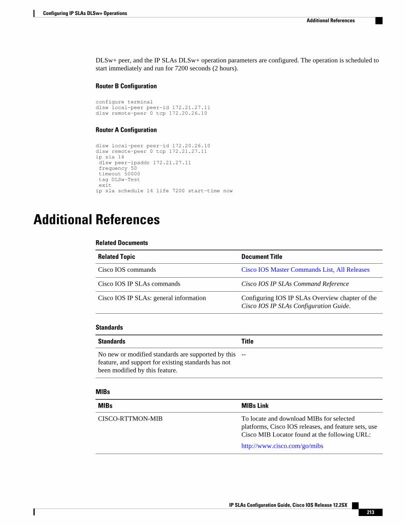
DLSw+ peer, and the IP SLAs DLSw+ operation parameters are configured. The operation is scheduled tostart immediately and run for 7200 seconds (2 hours).
Router B Configuration
configure terminaldlsw local-peer peer-id 172.21.27.11dlsw remote-peer 0 tcp 172.20.26.10
Router A Configuration
dlsw local-peer peer-id 172.20.26.10dlsw remote-peer 0 tcp 172.21.27.11ip sla 14 dlsw peer-ipaddr 172.21.27.11 frequency 50 timeout 50000 tag DLSw-Test exitip sla schedule 14 life 7200 start-time now
Additional ReferencesRelated Documents
Related Topic Document Title
Cisco IOS commands Cisco IOS Master Commands List, All Releases
Cisco IOS IP SLAs commands Cisco IOS IP SLAs Command Reference
Cisco IOS IP SLAs: general information Configuring IOS IP SLAs Overview chapter of theCisco IOS IP SLAs Configuration Guide.
Standards
Standards Title
No new or modified standards are supported by thisfeature, and support for existing standards has notbeen modified by this feature.
--
MIBs
MIBs MIBs Link
CISCO-RTTMON-MIB To locate and download MIBs for selectedplatforms, Cisco IOS releases, and feature sets, useCisco MIB Locator found at the following URL:
http://www.cisco.com/go/mibs
Configuring IP SLAs DLSw+ OperationsAdditional References
IP SLAs Configuration Guide, Cisco IOS Release 12.2SX 213
RFCs
RFCs Title
RFC 1795 Data Link Switching: Switch-to-Switch Protocol
Technical Assistance
Description Link
The Cisco Support and Documentation websiteprovides online resources to downloaddocumentation, software, and tools. Use theseresources to install and configure the software andto troubleshoot and resolve technical issues withCisco products and technologies. Access to mosttools on the Cisco Support and Documentationwebsite requires a Cisco.com user ID andpassword.
http://www.cisco.com/cisco/web/support/index.html
Feature Information for Cisco IOS IP SLAs DLSw+ OperationsThe following table provides release information about the feature or features described in this module.This table lists only the software release that introduced support for a given feature in a given softwarerelease train. Unless noted otherwise, subsequent releases of that software release train also support thatfeature.
Use Cisco Feature Navigator to find information about platform support and Cisco software image support.To access Cisco Feature Navigator, go to www.cisco.com/go/cfn. An account on Cisco.com is not required.
Table 23: Feature Information for Cisco IOS IP SLAs DLSw+ Operations
Feature Name Releases Feature Information
IP SLAs DLSw+ Operation 12.3(14)T 15.0(1)S The Cisco IOS IP SLAs DataLink Switching Plus (DLSw+)operation allows you to scheduleand measure the DLSw+ protocolstack and network response timebetween DLSw+ peers
Cisco and the Cisco Logo are trademarks of Cisco Systems, Inc. and/or its affiliates in the U.S. and othercountries. A listing of Cisco's trademarks can be found at www.cisco.com/go/trademarks. Third partytrademarks mentioned are the property of their respective owners. The use of the word partner does notimply a partnership relationship between Cisco and any other company. (1005R)
Any Internet Protocol (IP) addresses and phone numbers used in this document are not intended to beactual addresses and phone numbers. Any examples, command display output, network topology diagrams,
Configuring IP SLAs DLSw+ Operations Feature Information for Cisco IOS IP SLAs DLSw+ Operations
IP SLAs Configuration Guide, Cisco IOS Release 12.2SX214

and other figures included in the document are shown for illustrative purposes only. Any use of actual IPaddresses or phone numbers in illustrative content is unintentional and coincidental.
Configuring IP SLAs DLSw+ Operations
IP SLAs Configuration Guide, Cisco IOS Release 12.2SX 215

Example IP SLAs DLSw+ Operation Configuration
IP SLAs Configuration Guide, Cisco IOS Release 12.2SX216
Configuring an IP SLAs MultioperationScheduler
This document describes how to schedule multiple operations at once using the IP Service LevelAgreements (SLAs) Multioperations Scheduler feature.
• Finding Feature Information, page 217• Prerequisites for an IP SLAs Multioperation Scheduler, page 217• Information About an IP SLAs Multioperation Scheduler, page 218• How to Configure an IP SLAs Multioperation Scheduler, page 224• Configuration Examples for an IP SLAs Multioperation Scheduler, page 229• Additional References, page 229• Feature Information for a Cisco IOS IP SLAs Multioperation Scheduler, page 230
Finding Feature InformationYour software release may not support all the features documented in this module. For the latest featureinformation and caveats, see the release notes for your platform and software release. To find informationabout the features documented in this module, and to see a list of the releases in which each feature issupported, see the Feature Information Table at the end of this document.
Use Cisco Feature Navigator to find information about platform support and Cisco software image support.To access Cisco Feature Navigator, go to www.cisco.com/go/cfn. An account on Cisco.com is not required.
Prerequisites for an IP SLAs Multioperation Scheduler• Configure the IP SLAs operations to be included in a group before scheduling the group.• Determine the IP SLAs operations you want to schedule as a single group.• Identify the network traffic type and the location of your network management station.• Identify the topology and the types of devices in your network.• Decide on the frequency of testing for each operation.
IP SLAs Configuration Guide, Cisco IOS Release 12.2SX 217
Information About an IP SLAs Multioperation Scheduler• IP SLAs Multioperations Scheduler, page 218• IP SLAs Random Scheduler, page 224
IP SLAs Multioperations SchedulerNormal scheduling of IP SLAs operations allows you to schedule one operation at a time. If you have largenetworks with thousands of IP SLAs operations to monitor network performance, normal scheduling(scheduling each operation individually) will be inefficient and time-consuming.
Multiple operations scheduling allows you to schedule multiple IP SLAs operations using a singlecommand through the command line interface (CLI) or the CISCO-RTTMON-MIB. This feature allowsyou to control the amount of IP SLAs monitoring traffic by scheduling the operations to run at evenlydistributed times. You must specify the operation ID numbers to be scheduled and the time range overwhich all the IP SLAs operations should start. This feature automatically distributes the IP SLAs operationsat equal intervals over a specified time frame. The spacing between the operations (start interval) iscalculated and the operations are started. This distribution of IP SLAs operations helps minimize the CPUutilization and thereby enhances the scalability of the network.
The IP SLAs multiple operations scheduling functionality allows you to schedule multiple IP SLAsoperations as a group, using the following configuration parameters:
• Group operation number--Group configuration or group schedule number of the IP SLAs operation tobe scheduled.
• Operation ID numbers--A list of IP SLAs operation ID numbers in the scheduled operation group.• Schedule period--Amount of time for which the IP SLAs operation group is scheduled.• Ageout--Amount of time to keep the operation in memory when it is not actively collecting
information. By default, the operation remains in memory indefinitely.• Frequency--Amount of time after which each IP SLAs operation is restarted. When the frequency
option is specified, it overwrites the operation frequency of all operations belonging to the group. Notethat when the frequency option is not specified, the frequency for each operation is set to the value ofthe schedule period.
• Life--Amount of time the operation actively collects information. The operation can be configured torun indefinitely. By default, the lifetime of an operation is one hour.
• Start time--Time when the operation starts collecting information. You can specify an operation tostart immediately or at an absolute start time using hours, minutes, seconds, day, and month.
The IP SLAs multiple operations scheduling functionality schedules the maximum number of operationspossible without aborting. However, this functionality skips those IP SLAs operations that are alreadyrunning or those that are not configured and hence do not exist. The total number of operations will becalculated based on the number of operations specified in the command, irrespective of the number ofoperations that are missing or already running. The IP SLAs multiple operations scheduling functionalitydisplays a message showing the number of active and missing operations. However, these messages aredisplayed only if you schedule operations that are not configured or are already running.
A main benefit for scheduling multiple IP SLAs operations is that the load on the network is reduced bydistributing the operations equally over a scheduled period. This distribution helps you to achieve moreconsistent monitoring coverage. To illustrate this scenario, consider configuring 60 operations to startduring the same 1-second interval over a 60-second schedule period. If a network failure occurs 30 secondsafter all 60 operations have started and the network is restored before the operations are due to start again(in another 30 seconds), then this failure would never be detected by any of the 60 operations. However, if
IP SLAs Multioperations Scheduler Information About an IP SLAs Multioperation Scheduler
IP SLAs Configuration Guide, Cisco IOS Release 12.2SX218
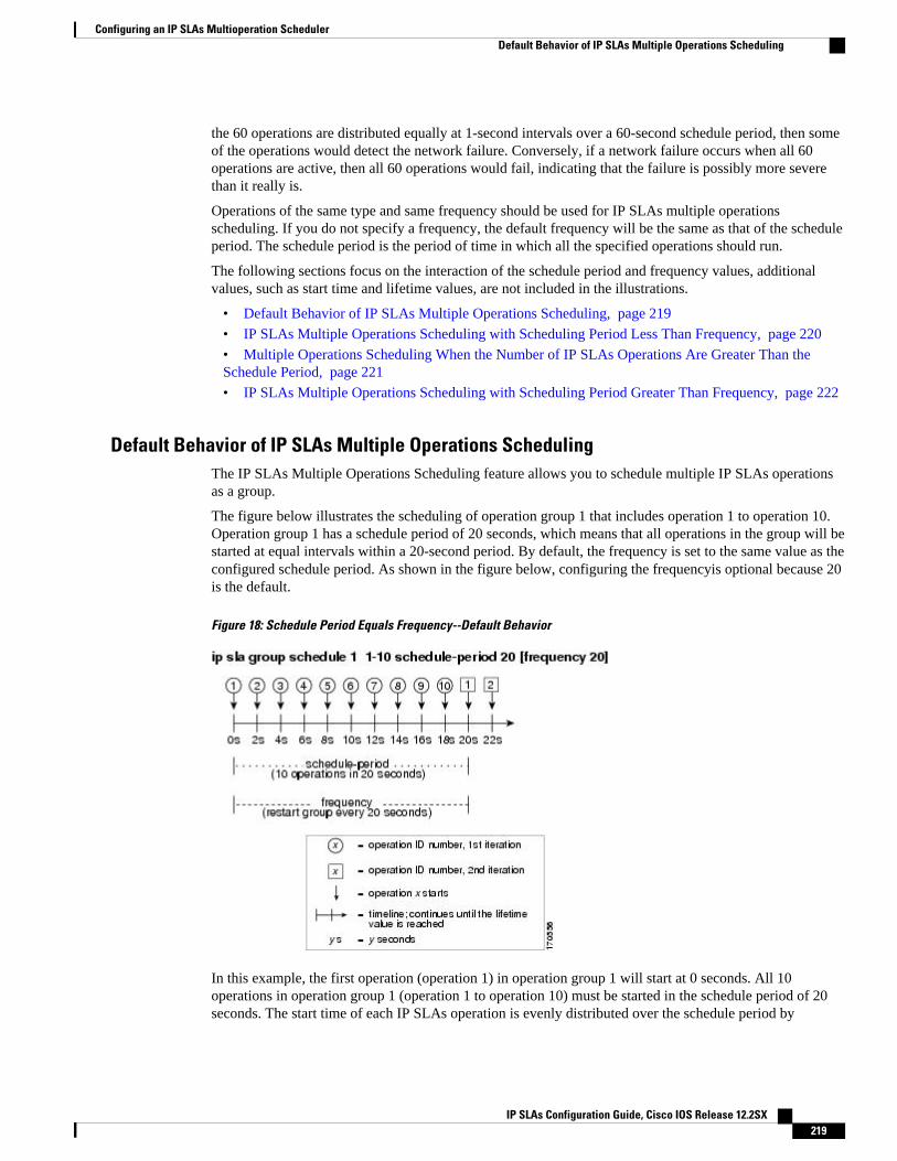
the 60 operations are distributed equally at 1-second intervals over a 60-second schedule period, then someof the operations would detect the network failure. Conversely, if a network failure occurs when all 60operations are active, then all 60 operations would fail, indicating that the failure is possibly more severethan it really is.
Operations of the same type and same frequency should be used for IP SLAs multiple operationsscheduling. If you do not specify a frequency, the default frequency will be the same as that of the scheduleperiod. The schedule period is the period of time in which all the specified operations should run.
The following sections focus on the interaction of the schedule period and frequency values, additionalvalues, such as start time and lifetime values, are not included in the illustrations.
• Default Behavior of IP SLAs Multiple Operations Scheduling, page 219
• IP SLAs Multiple Operations Scheduling with Scheduling Period Less Than Frequency, page 220
• Multiple Operations Scheduling When the Number of IP SLAs Operations Are Greater Than theSchedule Period, page 221
• IP SLAs Multiple Operations Scheduling with Scheduling Period Greater Than Frequency, page 222
Default Behavior of IP SLAs Multiple Operations SchedulingThe IP SLAs Multiple Operations Scheduling feature allows you to schedule multiple IP SLAs operationsas a group.
The figure below illustrates the scheduling of operation group 1 that includes operation 1 to operation 10.Operation group 1 has a schedule period of 20 seconds, which means that all operations in the group will bestarted at equal intervals within a 20-second period. By default, the frequency is set to the same value as theconfigured schedule period. As shown in the figure below, configuring the frequencyis optional because 20is the default.
Figure 18: Schedule Period Equals Frequency--Default Behavior
In this example, the first operation (operation 1) in operation group 1 will start at 0 seconds. All 10operations in operation group 1 (operation 1 to operation 10) must be started in the schedule period of 20seconds. The start time of each IP SLAs operation is evenly distributed over the schedule period by
Configuring an IP SLAs Multioperation SchedulerDefault Behavior of IP SLAs Multiple Operations Scheduling
IP SLAs Configuration Guide, Cisco IOS Release 12.2SX 219
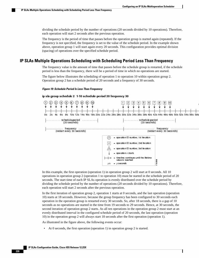
dividing the schedule period by the number of operations (20 seconds divided by 10 operations). Therefore,each operation will start 2 seconds after the previous operation.
The frequency is the period of time that passes before the operation group is started again (repeated). If thefrequency is not specified, the frequency is set to the value of the schedule period. In the example shownabove, operation group 1 will start again every 20 seconds. This configuration provides optimal division(spacing) of operations over the specified schedule period.
IP SLAs Multiple Operations Scheduling with Scheduling Period Less Than FrequencyThe frequency value is the amount of time that passes before the schedule group is restarted, if the scheduleperiod is less than the frequency, there will be a period of time in which no operations are started.
The figure below illustrates the scheduling of operation 1 to operation 10 within operation group 2.Operation group 2 has a schedule period of 20 seconds and a frequency of 30 seconds.
Figure 19: Schedule Period Is Less Than Frequency
In this example, the first operation (operation 1) in operation group 2 will start at 0 seconds. All 10operations in operation group 2 (operation 1 to operation 10) must be started in the schedule period of 20seconds. The start time of each IP SLAs operation is evenly distributed over the schedule period bydividing the schedule period by the number of operations (20 seconds divided by 10 operations). Therefore,each operation will start 2 seconds after the previous operation.
In the first iteration of operation group 2, operation 1 starts at 0 seconds, and the last operation (operation10) starts at 18 seconds. However, because the group frequency has been configured to 30 seconds eachoperation in the operation group is restarted every 30 seconds. So, after 18 seconds, there is a gap of 10seconds as no operations are started in the time from 19 seconds to 29 seconds. Hence, at 30 seconds, thesecond iteration of operation group 2 starts. As all ten operations in the operation group 2 must start at anevenly distributed interval in the configured schedule period of 20 seconds, the last operation (operation10) in the operation group 2 will always start 18 seconds after the first operation (operation 1).
As illustrated in the figure above, the following events occur:
• At 0 seconds, the first operation (operation 1) in operation group 2 is started.
Configuring an IP SLAs Multioperation Scheduler IP SLAs Multiple Operations Scheduling with Scheduling Period Less Than Frequency
IP SLAs Configuration Guide, Cisco IOS Release 12.2SX220
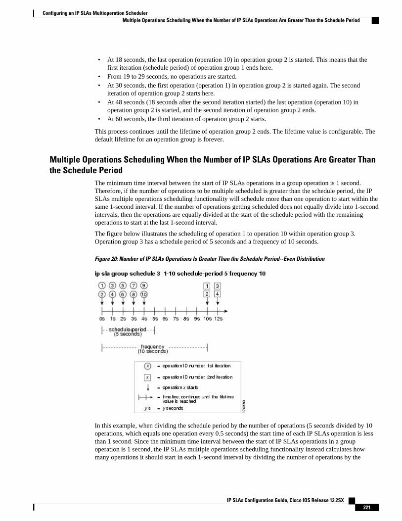
• At 18 seconds, the last operation (operation 10) in operation group 2 is started. This means that thefirst iteration (schedule period) of operation group 1 ends here.
• From 19 to 29 seconds, no operations are started.• At 30 seconds, the first operation (operation 1) in operation group 2 is started again. The second
iteration of operation group 2 starts here.• At 48 seconds (18 seconds after the second iteration started) the last operation (operation 10) in
operation group 2 is started, and the second iteration of operation group 2 ends.• At 60 seconds, the third iteration of operation group 2 starts.
This process continues until the lifetime of operation group 2 ends. The lifetime value is configurable. Thedefault lifetime for an operation group is forever.
Multiple Operations Scheduling When the Number of IP SLAs Operations Are Greater Thanthe Schedule Period
The minimum time interval between the start of IP SLAs operations in a group operation is 1 second.Therefore, if the number of operations to be multiple scheduled is greater than the schedule period, the IPSLAs multiple operations scheduling functionality will schedule more than one operation to start within thesame 1-second interval. If the number of operations getting scheduled does not equally divide into 1-secondintervals, then the operations are equally divided at the start of the schedule period with the remainingoperations to start at the last 1-second interval.
The figure below illustrates the scheduling of operation 1 to operation 10 within operation group 3.Operation group 3 has a schedule period of 5 seconds and a frequency of 10 seconds.
Figure 20: Number of IP SLAs Operations Is Greater Than the Schedule Period--Even Distribution
In this example, when dividing the schedule period by the number of operations (5 seconds divided by 10operations, which equals one operation every 0.5 seconds) the start time of each IP SLAs operation is lessthan 1 second. Since the minimum time interval between the start of IP SLAs operations in a groupoperation is 1 second, the IP SLAs multiple operations scheduling functionality instead calculates howmany operations it should start in each 1-second interval by dividing the number of operations by the
Configuring an IP SLAs Multioperation SchedulerMultiple Operations Scheduling When the Number of IP SLAs Operations Are Greater Than the Schedule Period
IP SLAs Configuration Guide, Cisco IOS Release 12.2SX 221
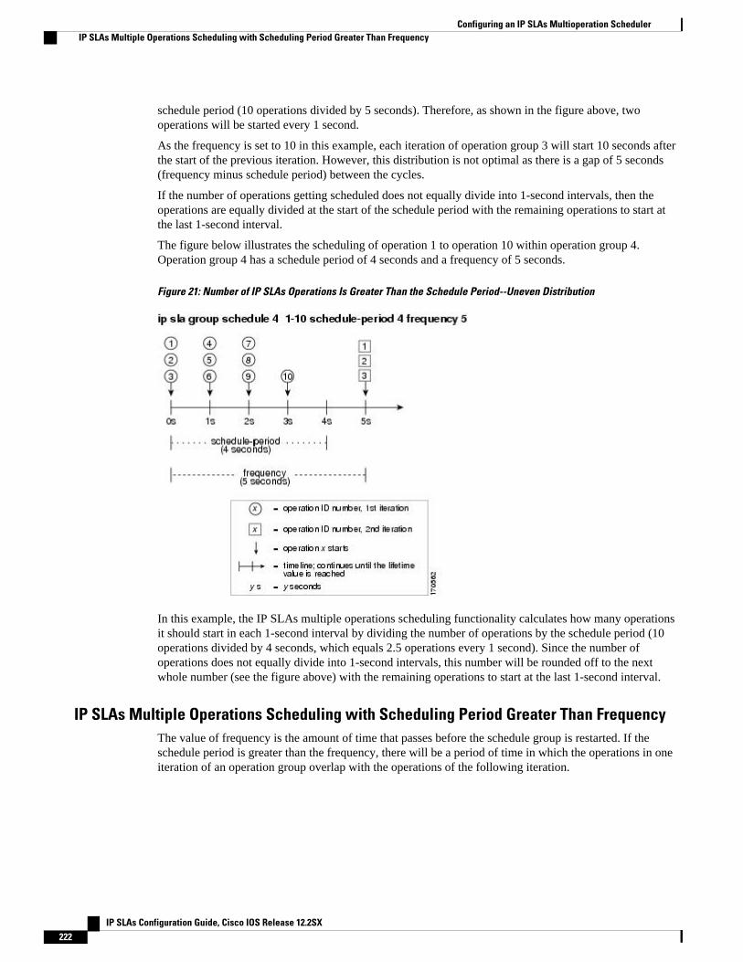
schedule period (10 operations divided by 5 seconds). Therefore, as shown in the figure above, twooperations will be started every 1 second.
As the frequency is set to 10 in this example, each iteration of operation group 3 will start 10 seconds afterthe start of the previous iteration. However, this distribution is not optimal as there is a gap of 5 seconds(frequency minus schedule period) between the cycles.
If the number of operations getting scheduled does not equally divide into 1-second intervals, then theoperations are equally divided at the start of the schedule period with the remaining operations to start atthe last 1-second interval.
The figure below illustrates the scheduling of operation 1 to operation 10 within operation group 4.Operation group 4 has a schedule period of 4 seconds and a frequency of 5 seconds.
Figure 21: Number of IP SLAs Operations Is Greater Than the Schedule Period--Uneven Distribution
In this example, the IP SLAs multiple operations scheduling functionality calculates how many operationsit should start in each 1-second interval by dividing the number of operations by the schedule period (10operations divided by 4 seconds, which equals 2.5 operations every 1 second). Since the number ofoperations does not equally divide into 1-second intervals, this number will be rounded off to the nextwhole number (see the figure above) with the remaining operations to start at the last 1-second interval.
IP SLAs Multiple Operations Scheduling with Scheduling Period Greater Than FrequencyThe value of frequency is the amount of time that passes before the schedule group is restarted. If theschedule period is greater than the frequency, there will be a period of time in which the operations in oneiteration of an operation group overlap with the operations of the following iteration.
Configuring an IP SLAs Multioperation Scheduler IP SLAs Multiple Operations Scheduling with Scheduling Period Greater Than Frequency
IP SLAs Configuration Guide, Cisco IOS Release 12.2SX222
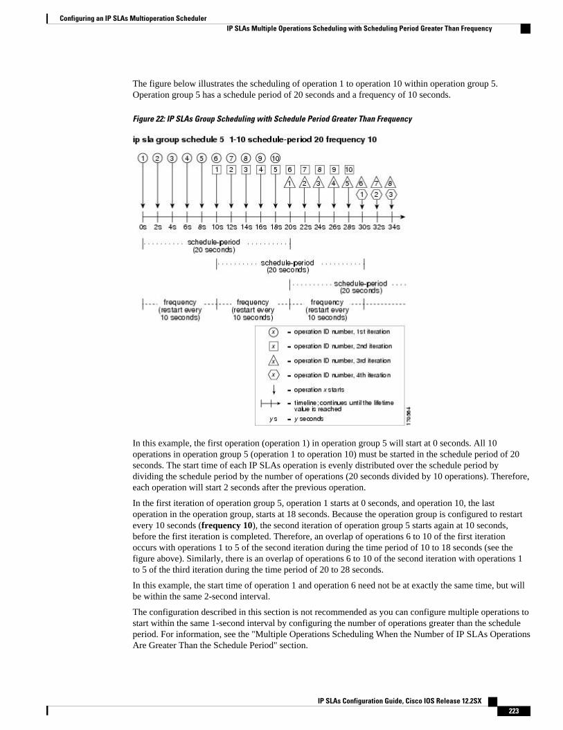
The figure below illustrates the scheduling of operation 1 to operation 10 within operation group 5.Operation group 5 has a schedule period of 20 seconds and a frequency of 10 seconds.
Figure 22: IP SLAs Group Scheduling with Schedule Period Greater Than Frequency
In this example, the first operation (operation 1) in operation group 5 will start at 0 seconds. All 10operations in operation group 5 (operation 1 to operation 10) must be started in the schedule period of 20seconds. The start time of each IP SLAs operation is evenly distributed over the schedule period bydividing the schedule period by the number of operations (20 seconds divided by 10 operations). Therefore,each operation will start 2 seconds after the previous operation.
In the first iteration of operation group 5, operation 1 starts at 0 seconds, and operation 10, the lastoperation in the operation group, starts at 18 seconds. Because the operation group is configured to restartevery 10 seconds (frequency 10), the second iteration of operation group 5 starts again at 10 seconds,before the first iteration is completed. Therefore, an overlap of operations 6 to 10 of the first iterationoccurs with operations 1 to 5 of the second iteration during the time period of 10 to 18 seconds (see thefigure above). Similarly, there is an overlap of operations 6 to 10 of the second iteration with operations 1to 5 of the third iteration during the time period of 20 to 28 seconds.
In this example, the start time of operation 1 and operation 6 need not be at exactly the same time, but willbe within the same 2-second interval.
The configuration described in this section is not recommended as you can configure multiple operations tostart within the same 1-second interval by configuring the number of operations greater than the scheduleperiod. For information, see the "Multiple Operations Scheduling When the Number of IP SLAs OperationsAre Greater Than the Schedule Period" section.
Configuring an IP SLAs Multioperation SchedulerIP SLAs Multiple Operations Scheduling with Scheduling Period Greater Than Frequency
IP SLAs Configuration Guide, Cisco IOS Release 12.2SX 223
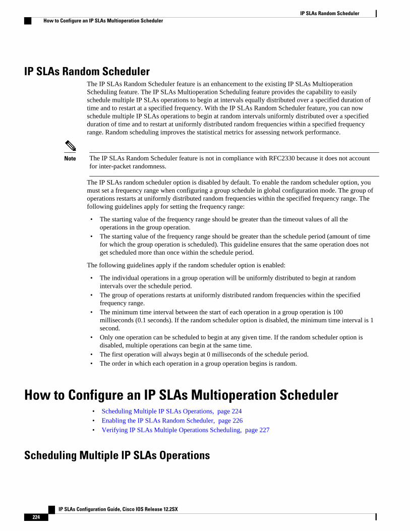
IP SLAs Random SchedulerThe IP SLAs Random Scheduler feature is an enhancement to the existing IP SLAs MultioperationScheduling feature. The IP SLAs Multioperation Scheduling feature provides the capability to easilyschedule multiple IP SLAs operations to begin at intervals equally distributed over a specified duration oftime and to restart at a specified frequency. With the IP SLAs Random Scheduler feature, you can nowschedule multiple IP SLAs operations to begin at random intervals uniformly distributed over a specifiedduration of time and to restart at uniformly distributed random frequencies within a specified frequencyrange. Random scheduling improves the statistical metrics for assessing network performance.
Note The IP SLAs Random Scheduler feature is not in compliance with RFC2330 because it does not accountfor inter-packet randomness.
The IP SLAs random scheduler option is disabled by default. To enable the random scheduler option, youmust set a frequency range when configuring a group schedule in global configuration mode. The group ofoperations restarts at uniformly distributed random frequencies within the specified frequency range. Thefollowing guidelines apply for setting the frequency range:
• The starting value of the frequency range should be greater than the timeout values of all theoperations in the group operation.
• The starting value of the frequency range should be greater than the schedule period (amount of timefor which the group operation is scheduled). This guideline ensures that the same operation does notget scheduled more than once within the schedule period.
The following guidelines apply if the random scheduler option is enabled:
• The individual operations in a group operation will be uniformly distributed to begin at randomintervals over the schedule period.
• The group of operations restarts at uniformly distributed random frequencies within the specifiedfrequency range.
• The minimum time interval between the start of each operation in a group operation is 100milliseconds (0.1 seconds). If the random scheduler option is disabled, the minimum time interval is 1second.
• Only one operation can be scheduled to begin at any given time. If the random scheduler option isdisabled, multiple operations can begin at the same time.
• The first operation will always begin at 0 milliseconds of the schedule period.• The order in which each operation in a group operation begins is random.
How to Configure an IP SLAs Multioperation Scheduler• Scheduling Multiple IP SLAs Operations, page 224
• Enabling the IP SLAs Random Scheduler, page 226
• Verifying IP SLAs Multiple Operations Scheduling, page 227
Scheduling Multiple IP SLAs Operations
IP SLAs Random Scheduler How to Configure an IP SLAs Multioperation Scheduler
IP SLAs Configuration Guide, Cisco IOS Release 12.2SX224
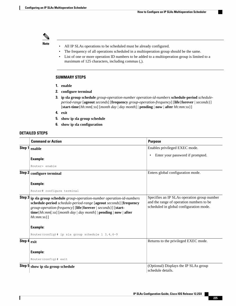
Note• All IP SLAs operations to be scheduled must be already configured.• The frequency of all operations scheduled in a multioperation group should be the same.• List of one or more operation ID numbers to be added to a multioperation group is limited to a
maximum of 125 characters, including commas (,).
SUMMARY STEPS
1. enable
2. configure terminal
3. ip sla group schedule group-operation-number operation-id-numbers schedule-period schedule-period-range [ageout seconds] [frequency group-operation-frequency] [life{forever | seconds}][start-time{hh:mm[:ss] [month day | day month] | pending | now | after hh:mm:ss}]
4. exit
5. show ip sla group schedule
6. show ip sla configuration
DETAILED STEPS
Command or Action Purpose
Step 1 enable
Example:
Router> enable
Enables privileged EXEC mode.
• Enter your password if prompted.
Step 2 configure terminal
Example:
Router# configure terminal
Enters global configuration mode.
Step 3 ip sla group schedule group-operation-number operation-id-numbersschedule-period schedule-period-range [ageout seconds] [frequencygroup-operation-frequency] [life{forever | seconds}] [start-time{hh:mm[:ss] [month day | day month] | pending | now | afterhh:mm:ss}]
Example:
Router(config)# ip sla group schedule 1 3,4,6-9
Specifies an IP SLAs operation group numberand the range of operation numbers to bescheduled in global configuration mode.
Step 4 exit
Example:
Router(config)# exit
Returns to the privileged EXEC mode.
Step 5 show ip sla group schedule (Optional) Displays the IP SLAs groupschedule details.
Configuring an IP SLAs Multioperation SchedulerHow to Configure an IP SLAs Multioperation Scheduler
IP SLAs Configuration Guide, Cisco IOS Release 12.2SX 225
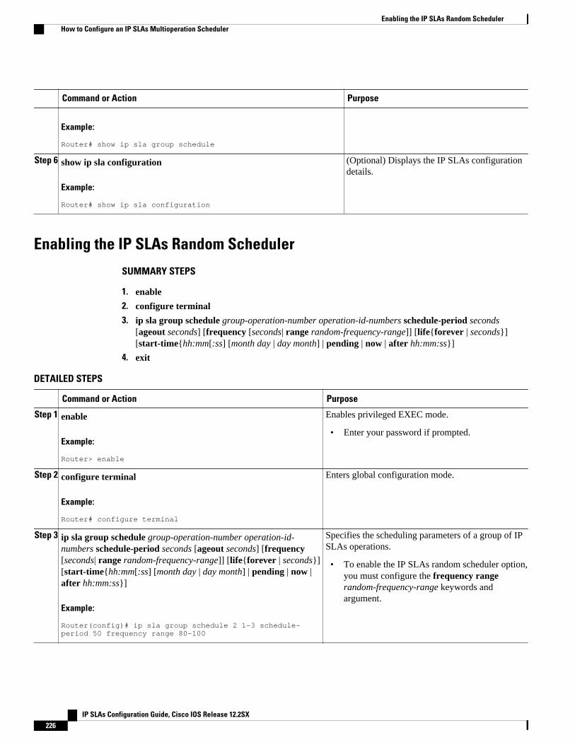
Command or Action Purpose
Example:
Router# show ip sla group schedule
Step 6 show ip sla configuration
Example:
Router# show ip sla configuration
(Optional) Displays the IP SLAs configurationdetails.
Enabling the IP SLAs Random Scheduler
SUMMARY STEPS
1. enable
2. configure terminal
3. ip sla group schedule group-operation-number operation-id-numbers schedule-period seconds[ageout seconds] [frequency [seconds| range random-frequency-range]] [life{forever | seconds}][start-time{hh:mm[:ss] [month day | day month] | pending | now | after hh:mm:ss}]
4. exit
DETAILED STEPS
Command or Action Purpose
Step 1 enable
Example:
Router> enable
Enables privileged EXEC mode.
• Enter your password if prompted.
Step 2 configure terminal
Example:
Router# configure terminal
Enters global configuration mode.
Step 3 ip sla group schedule group-operation-number operation-id-numbers schedule-period seconds [ageout seconds] [frequency[seconds| range random-frequency-range]] [life{forever | seconds}][start-time{hh:mm[:ss] [month day | day month] | pending | now |after hh:mm:ss}]
Example:
Router(config)# ip sla group schedule 2 1-3 schedule-period 50 frequency range 80-100
Specifies the scheduling parameters of a group of IPSLAs operations.
• To enable the IP SLAs random scheduler option,you must configure the frequency rangerandom-frequency-range keywords andargument.
Enabling the IP SLAs Random Scheduler How to Configure an IP SLAs Multioperation Scheduler
IP SLAs Configuration Guide, Cisco IOS Release 12.2SX226
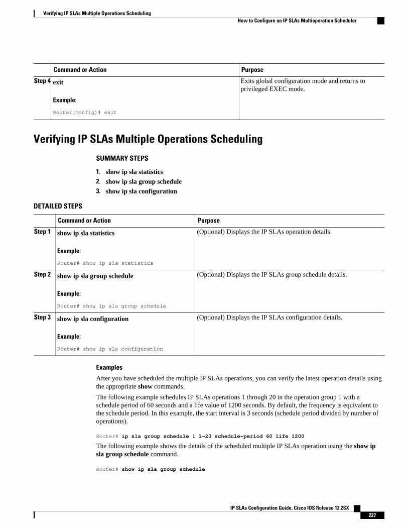
Command or Action Purpose
Step 4 exit
Example:
Router(config)# exit
Exits global configuration mode and returns toprivileged EXEC mode.
Verifying IP SLAs Multiple Operations Scheduling
SUMMARY STEPS
1. show ip sla statistics2. show ip sla group schedule3. show ip sla configuration
DETAILED STEPS
Command or Action Purpose
Step 1 show ip sla statistics
Example:
Router# show ip sla statistics
(Optional) Displays the IP SLAs operation details.
Step 2 show ip sla group schedule
Example:
Router# show ip sla group schedule
(Optional) Displays the IP SLAs group schedule details.
Step 3 show ip sla configuration
Example:
Router# show ip sla configuration
(Optional) Displays the IP SLAs configuration details.
Examples
After you have scheduled the multiple IP SLAs operations, you can verify the latest operation details usingthe appropriate show commands.
The following example schedules IP SLAs operations 1 through 20 in the operation group 1 with aschedule period of 60 seconds and a life value of 1200 seconds. By default, the frequency is equivalent tothe schedule period. In this example, the start interval is 3 seconds (schedule period divided by number ofoperations).
Router# ip sla group schedule 1 1-20 schedule-period 60 life 1200
The following example shows the details of the scheduled multiple IP SLAs operation using the show ipsla group schedule command.
Router# show ip sla group schedule
Verifying IP SLAs Multiple Operations SchedulingHow to Configure an IP SLAs Multioperation Scheduler
IP SLAs Configuration Guide, Cisco IOS Release 12.2SX 227
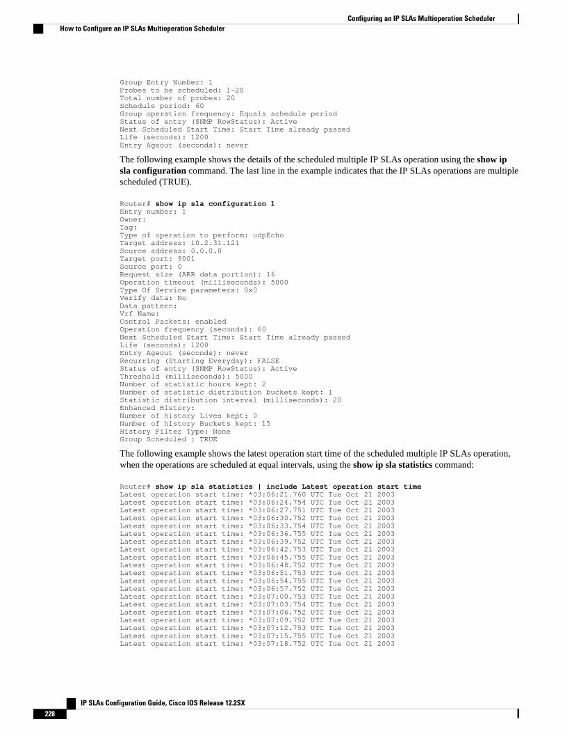
Group Entry Number: 1Probes to be scheduled: 1-20Total number of probes: 20Schedule period: 60Group operation frequency: Equals schedule periodStatus of entry (SNMP RowStatus): ActiveNext Scheduled Start Time: Start Time already passedLife (seconds): 1200Entry Ageout (seconds): never
The following example shows the details of the scheduled multiple IP SLAs operation using the show ipsla configuration command. The last line in the example indicates that the IP SLAs operations are multiplescheduled (TRUE).
Router# show ip sla configuration 1Entry number: 1Owner: Tag: Type of operation to perform: udpEchoTarget address: 10.2.31.121Source address: 0.0.0.0Target port: 9001Source port: 0Request size (ARR data portion): 16Operation timeout (milliseconds): 5000Type Of Service parameters: 0x0Verify data: NoData pattern: Vrf Name: Control Packets: enabledOperation frequency (seconds): 60Next Scheduled Start Time: Start Time already passedLife (seconds): 1200Entry Ageout (seconds): neverRecurring (Starting Everyday): FALSEStatus of entry (SNMP RowStatus): ActiveThreshold (milliseconds): 5000Number of statistic hours kept: 2Number of statistic distribution buckets kept: 1Statistic distribution interval (milliseconds): 20Enhanced History:Number of history Lives kept: 0Number of history Buckets kept: 15History Filter Type: NoneGroup Scheduled : TRUE
The following example shows the latest operation start time of the scheduled multiple IP SLAs operation,when the operations are scheduled at equal intervals, using the show ip sla statistics command:
Router# show ip sla statistics | include Latest operation start timeLatest operation start time: *03:06:21.760 UTC Tue Oct 21 2003Latest operation start time: *03:06:24.754 UTC Tue Oct 21 2003Latest operation start time: *03:06:27.751 UTC Tue Oct 21 2003Latest operation start time: *03:06:30.752 UTC Tue Oct 21 2003Latest operation start time: *03:06:33.754 UTC Tue Oct 21 2003Latest operation start time: *03:06:36.755 UTC Tue Oct 21 2003Latest operation start time: *03:06:39.752 UTC Tue Oct 21 2003Latest operation start time: *03:06:42.753 UTC Tue Oct 21 2003Latest operation start time: *03:06:45.755 UTC Tue Oct 21 2003Latest operation start time: *03:06:48.752 UTC Tue Oct 21 2003Latest operation start time: *03:06:51.753 UTC Tue Oct 21 2003Latest operation start time: *03:06:54.755 UTC Tue Oct 21 2003Latest operation start time: *03:06:57.752 UTC Tue Oct 21 2003Latest operation start time: *03:07:00.753 UTC Tue Oct 21 2003Latest operation start time: *03:07:03.754 UTC Tue Oct 21 2003Latest operation start time: *03:07:06.752 UTC Tue Oct 21 2003Latest operation start time: *03:07:09.752 UTC Tue Oct 21 2003Latest operation start time: *03:07:12.753 UTC Tue Oct 21 2003Latest operation start time: *03:07:15.755 UTC Tue Oct 21 2003Latest operation start time: *03:07:18.752 UTC Tue Oct 21 2003
Configuring an IP SLAs Multioperation Scheduler How to Configure an IP SLAs Multioperation Scheduler
IP SLAs Configuration Guide, Cisco IOS Release 12.2SX228
Configuration Examples for an IP SLAs MultioperationScheduler
• Example Scheduling Multiple IP SLAs Operations, page 229
• Example Enabling the IP SLAs Random Scheduler, page 229
Example Scheduling Multiple IP SLAs OperationsThe following example schedules IP SLAs operations 1 to 10 in the operation group 1 with a scheduleperiod of 20 seconds. By default, the frequency is equivalent to the schedule period.
Router# ip sla group schedule 1 1-10 schedule-period 20
The following example shows the details of the scheduled multiple IP SLAs operation using the show ipsla group schedule command. The last line in the example indicates that the IP SLAs operations aremultiple scheduled (TRUE).
Router# show ip sla group scheduleMulti-Scheduling Configuration:Group Entry Number: 1Probes to be scheduled: 1-10Schedule period :20Group operation frequency: 20Multi-scheduled: TRUE
Example Enabling the IP SLAs Random SchedulerThe following example shows how to schedule IP SLAs operations 1 to 3 as a group (identified as group2). In this example, the operations are scheduled to begin at uniformly distributed random intervals over aschedule period of 50 seconds. The first operation is scheduled to start immediately. The interval is chosenfrom the specified range upon every invocation of the probe. The random scheduler option is enabled andthe uniformly distributed random frequencies at which the group of operations will restart is chosen withinthe range of 80-100 seconds.
ip sla group schedule 2 1-3 schedule-period 50 frequency range 80-100 start-time now
Additional ReferencesRelated Documents
Related Topic Document Title
Cisco IOS commands Cisco IOS Master Commands List, All Releases
Cisco IOS IP SLAs commands Cisco IOS IP SLAs Command Reference
Example Scheduling Multiple IP SLAs OperationsConfiguration Examples for an IP SLAs Multioperation Scheduler
IP SLAs Configuration Guide, Cisco IOS Release 12.2SX 229
Standards
Standards Title
No new or modified standards are supported by thisfeature.
--
MIBs
MIBs MIBs Link
CISCO-RTTMON-MIB To locate and download MIBs for selectedplatforms, Cisco IOS releases, and feature sets, useCisco MIB Locator found at the following URL:
http://www.cisco.com/go/mibs
RFCs
RFCs Title
No new or modified RFCs are supported by thisfeature.
--
Technical Assistance
Description Link
The Cisco Support and Documentation websiteprovides online resources to downloaddocumentation, software, and tools. Use theseresources to install and configure the software andto troubleshoot and resolve technical issues withCisco products and technologies. Access to mosttools on the Cisco Support and Documentationwebsite requires a Cisco.com user ID andpassword.
http://www.cisco.com/cisco/web/support/index.html
Feature Information for a Cisco IOS IP SLAs MultioperationScheduler
The following table provides release information about the feature or features described in this module.This table lists only the software release that introduced support for a given feature in a given softwarerelease train. Unless noted otherwise, subsequent releases of that software release train also support thatfeature.
Use Cisco Feature Navigator to find information about platform support and Cisco software image support.To access Cisco Feature Navigator, go to www.cisco.com/go/cfn. An account on Cisco.com is not required.
Configuring an IP SLAs Multioperation Scheduler Feature Information for a Cisco IOS IP SLAs Multioperation Scheduler
IP SLAs Configuration Guide, Cisco IOS Release 12.2SX230
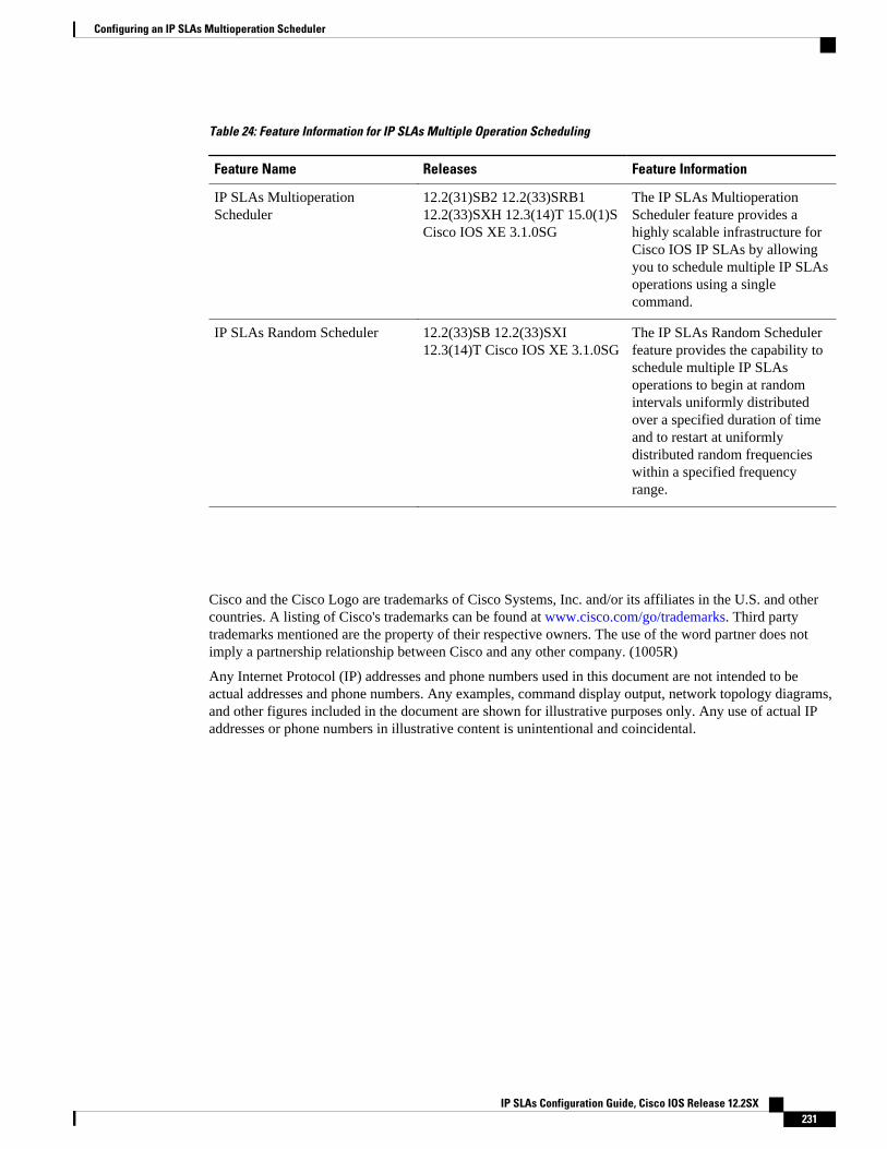
Table 24: Feature Information for IP SLAs Multiple Operation Scheduling
Feature Name Releases Feature Information
IP SLAs MultioperationScheduler
12.2(31)SB2 12.2(33)SRB112.2(33)SXH 12.3(14)T 15.0(1)SCisco IOS XE 3.1.0SG
The IP SLAs MultioperationScheduler feature provides ahighly scalable infrastructure forCisco IOS IP SLAs by allowingyou to schedule multiple IP SLAsoperations using a singlecommand.
IP SLAs Random Scheduler 12.2(33)SB 12.2(33)SXI12.3(14)T Cisco IOS XE 3.1.0SG
The IP SLAs Random Schedulerfeature provides the capability toschedule multiple IP SLAsoperations to begin at randomintervals uniformly distributedover a specified duration of timeand to restart at uniformlydistributed random frequencieswithin a specified frequencyrange.
Cisco and the Cisco Logo are trademarks of Cisco Systems, Inc. and/or its affiliates in the U.S. and othercountries. A listing of Cisco's trademarks can be found at www.cisco.com/go/trademarks. Third partytrademarks mentioned are the property of their respective owners. The use of the word partner does notimply a partnership relationship between Cisco and any other company. (1005R)
Any Internet Protocol (IP) addresses and phone numbers used in this document are not intended to beactual addresses and phone numbers. Any examples, command display output, network topology diagrams,and other figures included in the document are shown for illustrative purposes only. Any use of actual IPaddresses or phone numbers in illustrative content is unintentional and coincidental.
Configuring an IP SLAs Multioperation Scheduler
IP SLAs Configuration Guide, Cisco IOS Release 12.2SX 231

Example Enabling the IP SLAs Random Scheduler
IP SLAs Configuration Guide, Cisco IOS Release 12.2SX232
Configuring Proactive Threshold Monitoring forIP SLAs Operations
This document describes the proactive monitoring capabilities of IP Service Level Agreements (SLAs)using thresholds and reaction triggering.
• Finding Feature Information, page 233• Information About Proactive Threshold Monitoring, page 233• How to Configure Proactive Threshold Monitoring, page 239• Configuration Examples for Proactive Threshold Monitoring, page 241• Additional References, page 243• Feature Information for IP SLAs Proactive Threshold Monitoring, page 244
Finding Feature InformationYour software release may not support all the features documented in this module. For the latest featureinformation and caveats, see the release notes for your platform and software release. To find informationabout the features documented in this module, and to see a list of the releases in which each feature issupported, see the Feature Information Table at the end of this document.
Use Cisco Feature Navigator to find information about platform support and Cisco software image support.To access Cisco Feature Navigator, go to www.cisco.com/go/cfn. An account on Cisco.com is not required.
Information About Proactive Threshold Monitoring• IP SLAs Reaction Configuration, page 233
• IP SLAs Threshold Monitoring and Notifications, page 237
IP SLAs Reaction ConfigurationIP SLAs reactions are configured to trigger when a monitored value exceeds or falls below a specified levelor when a monitored event, such as a timeout or connection loss, occurs. If IP SLAs measures too high ortoo low of any configured reaction, IP SLAs can generate a notification to a network managementapplication or trigger another IP SLA operation to gather more data.
• Supported Reactions by IP SLAs Operation, page 234
IP SLAs Configuration Guide, Cisco IOS Release 12.2SX 233
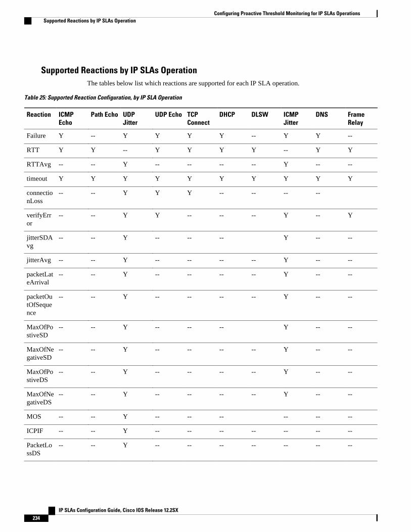
Supported Reactions by IP SLAs OperationThe tables below list which reactions are supported for each IP SLA operation.
Table 25: Supported Reaction Configuration, by IP SLA Operation
Reaction ICMPEcho
Path Echo UDPJitter
UDP Echo TCPConnect
DHCP DLSW ICMPJitter
DNS FrameRelay
Failure Y -- Y Y Y Y -- Y Y --
RTT Y Y -- Y Y Y Y -- Y Y
RTTAvg -- -- Y -- -- -- -- Y -- --
timeout Y Y Y Y Y Y Y Y Y Y
connectionLoss
-- -- Y Y Y -- -- -- --
verifyError
-- -- Y Y -- -- -- Y -- Y
jitterSDAvg
-- -- Y -- -- -- Y -- --
jitterAvg -- -- Y -- -- -- -- Y -- --
packetLateArrival
-- -- Y -- -- -- -- Y -- --
packetOutOfSequence
-- -- Y -- -- -- -- Y -- --
MaxOfPostiveSD
-- -- Y -- -- -- Y -- --
MaxOfNegativeSD
-- -- Y -- -- -- -- Y -- --
MaxOfPostiveDS
-- -- Y -- -- -- -- Y -- --
MaxOfNegativeDS
-- -- Y -- -- -- -- Y -- --
MOS -- -- Y -- -- -- -- -- --
ICPIF -- -- Y -- -- -- -- -- -- --
PacketLossDS
-- -- Y -- -- -- -- -- -- --
Configuring Proactive Threshold Monitoring for IP SLAs Operations Supported Reactions by IP SLAs Operation
IP SLAs Configuration Guide, Cisco IOS Release 12.2SX234
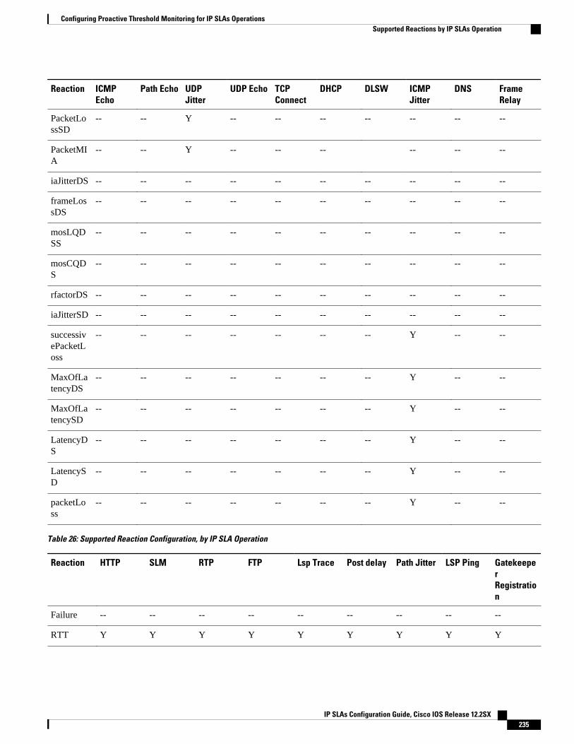
Reaction ICMPEcho
Path Echo UDPJitter
UDP Echo TCPConnect
DHCP DLSW ICMPJitter
DNS FrameRelay
PacketLossSD
-- -- Y -- -- -- -- -- -- --
PacketMIA
-- -- Y -- -- -- -- -- --
iaJitterDS -- -- -- -- -- -- -- -- -- --
frameLossDS
-- -- -- -- -- -- -- -- -- --
mosLQDSS
-- -- -- -- -- -- -- -- -- --
mosCQDS
-- -- -- -- -- -- -- -- -- --
rfactorDS -- -- -- -- -- -- -- -- -- --
iaJitterSD -- -- -- -- -- -- -- -- -- --
successivePacketLoss
-- -- -- -- -- -- -- Y -- --
MaxOfLatencyDS
-- -- -- -- -- -- -- Y -- --
MaxOfLatencySD
-- -- -- -- -- -- -- Y -- --
LatencyDS
-- -- -- -- -- -- -- Y -- --
LatencySD
-- -- -- -- -- -- -- Y -- --
packetLoss
-- -- -- -- -- -- -- Y -- --
Table 26: Supported Reaction Configuration, by IP SLA Operation
Reaction HTTP SLM RTP FTP Lsp Trace Post delay Path Jitter LSP Ping GatekeeperRegistration
Failure -- -- -- -- -- -- -- -- --
RTT Y Y Y Y Y Y Y Y Y
Configuring Proactive Threshold Monitoring for IP SLAs OperationsSupported Reactions by IP SLAs Operation
IP SLAs Configuration Guide, Cisco IOS Release 12.2SX 235
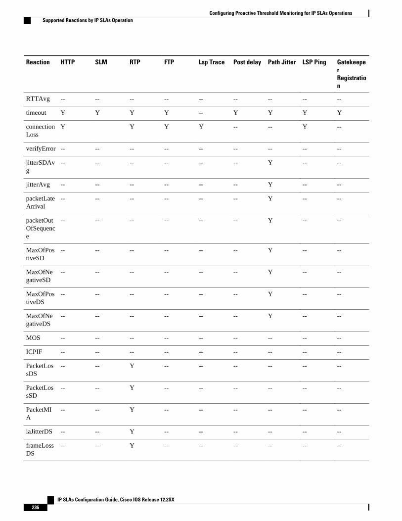
Reaction HTTP SLM RTP FTP Lsp Trace Post delay Path Jitter LSP Ping GatekeeperRegistration
RTTAvg -- -- -- -- -- -- -- -- --
timeout Y Y Y Y -- Y Y Y Y
connectionLoss
Y Y Y Y -- -- Y --
verifyError -- -- -- -- -- -- -- -- --
jitterSDAvg
-- -- -- -- -- -- Y -- --
jitterAvg -- -- -- -- -- -- Y -- --
packetLateArrival
-- -- -- -- -- -- Y -- --
packetOutOfSequence
-- -- -- -- -- -- Y -- --
MaxOfPostiveSD
-- -- -- -- -- -- Y -- --
MaxOfNegativeSD
-- -- -- -- -- -- Y -- --
MaxOfPostiveDS
-- -- -- -- -- -- Y -- --
MaxOfNegativeDS
-- -- -- -- -- -- Y -- --
MOS -- -- -- -- -- -- -- -- --
ICPIF -- -- -- -- -- -- -- -- --
PacketLossDS
-- -- Y -- -- -- -- -- --
PacketLossSD
-- -- Y -- -- -- -- -- --
PacketMIA
-- -- Y -- -- -- -- -- --
iaJitterDS -- -- Y -- -- -- -- -- --
frameLossDS
-- -- Y -- -- -- -- -- --
Configuring Proactive Threshold Monitoring for IP SLAs Operations Supported Reactions by IP SLAs Operation
IP SLAs Configuration Guide, Cisco IOS Release 12.2SX236

Reaction HTTP SLM RTP FTP Lsp Trace Post delay Path Jitter LSP Ping GatekeeperRegistration
mosLQDSS
-- -- Y -- -- -- -- -- --
mosCQDS -- -- Y -- -- -- -- -- --
rfactorDS -- -- Y
iaJitterSD -- -- Y -- -- -- -- -- --
successivePacketLoss
-- -- -- -- -- -- -- -- --
MaxOfLatencyDS
-- -- -- -- -- -- -- -- --
MaxOfLatencySD
-- -- -- -- -- -- -- -- --
LatencyDS -- -- -- -- -- -- -- -- --
LatencySD -- -- -- -- -- -- -- -- --
packetLoss -- -- -- -- -- -- -- -- --
IP SLAs Threshold Monitoring and NotificationsIP SLAs supports proactive threshold monitoring and notifications for performance parameters such asaverage jitter, unidirectional latency, bidirectional round-trip time (RTT), and connectivity for most IPSLAs operations. The proactive monitoring capability also provides options for configuring reactionthresholds for important VoIP related parameters including unidirectional jitter, unidirectional packet loss,and unidirectional VoIP voice quality scoring.
Notifications for IP SLAs are configured as a triggered reaction. Packet loss, jitter, and Mean OperationScore (MOS) statistics are specific to IP SLAs jitter operations. Notifications can be generated forviolations in either direction (source-to-destination and destination-to-source) or for out-of-range RTTvalues for packet loss and jitter. Events, such as traps, are triggered when the RTT value rises above or fallsbelow a specified threshold.
IP SLAs can generate system logging (syslog) messages when a reaction condition occurs. System loggingmessages can be sent as Simple Network Management Protocol (SNMP) traps (notifications) using theCISCO-RTTMON-MIB. SNMP traps for IP SLAs are supported by the CISCO-RTTMON-MIB andCISCO-SYSLOG-MIB.
Severity levels in the CISCO-SYSLOG-MIB are defined as follows: SyslogSeverity INTEGER{emergency(1), alert(2), critical(3), error(4), warning(5), notice(6), info(7), debug(8)}
The values for severity levels are defined differently for the system logging process in software. Severitylevels for the system logging process in Cisco software are defined as follows: {emergency (0), alert (1),critical (2), error (3), warning (4), notice (5), informational (6), debugging (7)}.
IP SLAs Threshold Monitoring and NotificationsSupported Reactions by IP SLAs Operation
IP SLAs Configuration Guide, Cisco IOS Release 12.2SX 237
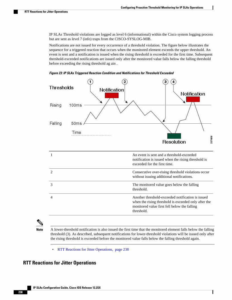
IP SLAs Threshold violations are logged as level 6 (informational) within the Cisco system logging processbut are sent as level 7 (info) traps from the CISCO-SYSLOG-MIB.
Notifications are not issued for every occurrence of a threshold violation. The figure below illustrates thesequence for a triggered reaction that occurs when the monitored element exceeds the upper threshold. Anevent is sent and a notification is issued when the rising threshold is exceeded for the first time. Subsequentthreshold-exceeded notifications are issued only after the monitored value falls below the falling thresholdbefore exceeding the rising threshold ag ain .
Figure 23: IP SLAs Triggered Reaction Condition and Notifications for Threshold Exceeded
1 An event is sent and a threshold-exceedednotification is issued when the rising threshold isexceeded for the first time.
2 Consecutive over-rising threshold violations occurwithout issuing additional notifications.
3 The monitored value goes below the fallingthreshold.
4 Another threshold-exceeded notification is issuedwhen the rising threshold is exceeded only after themonitored value first fell below the fallingthreshold.
Note A lower-threshold notification is also issued the first time that the monitored element falls below the fallingthreshold (3). As described, subsequent notifications for lower-threshold violations will be issued only afterthe rising threshold is exceeded before the monitored value falls below the falling threshold again.
• RTT Reactions for Jitter Operations, page 238
RTT Reactions for Jitter Operations
Configuring Proactive Threshold Monitoring for IP SLAs Operations RTT Reactions for Jitter Operations
IP SLAs Configuration Guide, Cisco IOS Release 12.2SX238
RTT reactions for jitter operations are triggered only at the end of the operation and use the latest value forthe return-trip time (LatestRTT), which matches the value of the average return-trip time (RTTAvg).
SNMP traps for RTT for jitter operations are based on the value of the average return-trip time (RTTAvg)for the whole operation and do not include RTT values for each individual packet sent during the operation.For example, if the average is below the threshold, up to half of the packets can actually be above thresholdbut this detail is not included in the notification because the value is for the whole operation only.
Only syslog messages are supported for RTTAvg threshold violations. Syslog nmessages are sent from theCISCO-RTTMON-MIB.
How to Configure Proactive Threshold Monitoring• Configuring Proactive Threshold Monitoring, page 239
Configuring Proactive Threshold MonitoringPerform this task to configure thresholds and reactive triggering for generating traps or starting anotheroperation.
• IP SLAs operations to be started when violation conditions are met must be configured.
Note• RTT reactions for jitter operations are triggered only at the end of the operation and use the latest
value for the return-trip time (LatestRTT).• SNMP traps for RTT for jitter operations are based on the average value for the return-trip time
(RTTAvg) for the whole operation only and do not include return-trip time values for individualpackets sent during the operation. Only syslog messages are supported for RTTAvg thresholdviolations.
• Only syslog messages are supported for RTT violations during Jitter operations.• Only SNMP traps are supported for RTT violations during non-Jitter operations.• Only syslog messages are supported for non-RTT violations other than timeout, connectionLoss, or
verifyError.• Both SNMP traps and syslog messages are supported for timeout, connectionLoss, or verifyError
violations only.
Configuring Proactive Threshold MonitoringHow to Configure Proactive Threshold Monitoring
IP SLAs Configuration Guide, Cisco IOS Release 12.2SX 239
SUMMARY STEPS
1. enable
2. configure terminal
3. ip sla reaction-configuration operation-number react monitored-element [action-type option][threshold-type {average [number-of-measurements] | consecutive [occurrences] | immediate | never| xofy [x-value y-value]}] [threshold-value upper-threshold lower-threshold]
4. ip sla reaction-trigger operation-number target-operation
5. ip sla logging traps
6. Do one of the following:
• snmp-server enable traps rtr• snmp-server enable traps syslog
7. snmp-server host {hostname | ip-address} [vrf vrf-name] [traps | informs] [version {1 | 2c | 3 [auth |noauth | priv]}] community-string [udp-port port] [notification-type]
8. exit
9. show ip sla reaction configuration [operation-number]
10. show ip sla reaction trigger [operation-number]
DETAILED STEPS
Command or Action Purpose
Step 1 enable
Example:
Router> enable
Enables privileged EXEC mode.
• Enter your password if prompted.
Step 2 configure terminal
Example:
Router# configure terminal
Enters global configuration mode.
Step 3 ip sla reaction-configuration operation-number reactmonitored-element [action-type option] [threshold-type{average [number-of-measurements] | consecutive[occurrences] | immediate | never | xofy [x-value y-value]}][threshold-value upper-threshold lower-threshold]
Example:
Router(config)# ip sla reaction-configuration 10 react jitterAvg threshold-type immediate threshold-value 5000 3000 action-type trapAndTrigger
Configures the action (SNMP trap or IP SLAs trigger)that is to occur based on violations of specifiedthresholds.
Step 4 ip sla reaction-trigger operation-number target-operation
Example:
Router(config)# ip sla reaction-trigger 10 2
(Optional) Starts another IP SLAs operation when theviolation conditions are met.
Configuring Proactive Threshold Monitoring for IP SLAs Operations How to Configure Proactive Threshold Monitoring
IP SLAs Configuration Guide, Cisco IOS Release 12.2SX240
Command or Action Purpose
• Required only if the ip sla reaction-configurationcommand is configured with either thetrapAndTriggeror triggerOnlykeyword.
Step 5 ip sla logging traps
Example:
Router(config)# ip sla logging traps
(Optional) Enables IP SLAs syslog messages fromCISCO-RTTMON-MIB.
Step 6 Do one of the following:
• snmp-server enable traps rtr• snmp-server enable traps syslog
Example:
Router(config)# snmp-server enable traps rtr
Example:
Router(config)# snmp-server enable traps syslog
(Optional) Enables system to generate CISCO-RTTMON-MIB traps.
or
Enables system to generate CISCO-SYSLOG-MIB traps.
Step 7 snmp-server host {hostname | ip-address} [vrf vrf-name][traps | informs] [version {1 | 2c | 3 [auth | noauth | priv]}]community-string [udp-port port] [notification-type]
Example:
Router(config)# snmp-server host 10.1.1.1 public syslog
(Optional) Sends traps to a remote host.
• Required if the snmp-server enable trapscommand is configured.
Step 8 exit
Example:
Router(config)# exit
Exits global configuration mode and returns to privilegedEXEC mode.
Step 9 show ip sla reaction configuration [operation-number]
Example:
Router# show ip sla reaction configuration 10
(Optional) Displays the configuration of proactivethreshold monitoring.
Step 10 show ip sla reaction trigger [operation-number]
Example:
Router# show ip sla reaction trigger 2
(Optional) Displays the configuration status andoperational state of target operations to be triggered.
Configuration Examples for Proactive Threshold Monitoring
Configuring Proactive Threshold Monitoring for IP SLAs OperationsConfiguration Examples for Proactive Threshold Monitoring
IP SLAs Configuration Guide, Cisco IOS Release 12.2SX 241
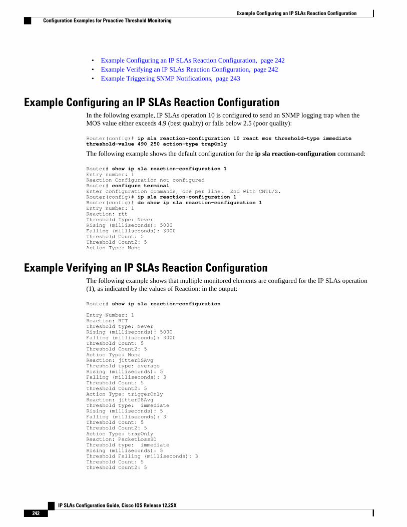
• Example Configuring an IP SLAs Reaction Configuration, page 242• Example Verifying an IP SLAs Reaction Configuration, page 242• Example Triggering SNMP Notifications, page 243
Example Configuring an IP SLAs Reaction ConfigurationIn the following example, IP SLAs operation 10 is configured to send an SNMP logging trap when theMOS value either exceeds 4.9 (best quality) or falls below 2.5 (poor quality):
Router(config)# ip sla reaction-configuration 10 react mos threshold-type immediate threshold-value 490 250 action-type trapOnly
The following example shows the default configuration for the ip sla reaction-configuration command:
Router# show ip sla reaction-configuration 1Entry number: 1Reaction Configuration not configuredRouter# configure terminalEnter configuration commands, one per line. End with CNTL/Z.Router(config)# ip sla reaction-configuration 1Router(config)# do show ip sla reaction-configuration 1Entry number: 1Reaction: rttThreshold Type: NeverRising (milliseconds): 5000Falling (milliseconds): 3000Threshold Count: 5Threshold Count2: 5Action Type: None
Example Verifying an IP SLAs Reaction ConfigurationThe following example shows that multiple monitored elements are configured for the IP SLAs operation(1), as indicated by the values of Reaction: in the output:
Router# show ip sla reaction-configuration Entry Number: 1Reaction: RTTThreshold type: NeverRising (milliseconds): 5000Falling (milliseconds): 3000Threshold Count: 5Threshold Count2: 5Action Type: NoneReaction: jitterDSAvgThreshold type: averageRising (milliseconds): 5Falling (milliseconds): 3Threshold Count: 5Threshold Count2: 5Action Type: triggerOnlyReaction: jitterDSAvgThreshold type: immediateRising (milliseconds): 5Falling (milliseconds): 3Threshold Count: 5Threshold Count2: 5Action Type: trapOnlyReaction: PacketLossSD Threshold type: immediateRising (milliseconds): 5Threshold Falling (milliseconds): 3Threshold Count: 5Threshold Count2: 5
Example Configuring an IP SLAs Reaction Configuration Configuration Examples for Proactive Threshold Monitoring
IP SLAs Configuration Guide, Cisco IOS Release 12.2SX242
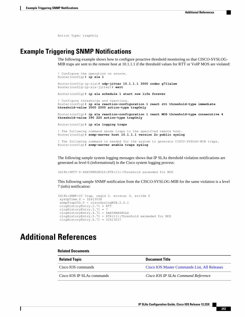
Action Type: trapOnly
Example Triggering SNMP NotificationsThe following example shows how to configure proactive threshold monitoring so that CISCO-SYSLOG-MIB traps are sent to the remote host at 10.1.1.1 if the threshold values for RTT or VoIP MOS are violated:
! Configure the operation on source.Router(config)# ip sla 1 Router(config-ip-sla)# udp-jitter 10.1.1.1 3000 codec g711alawRouter(config-ip-sla-jitter)# exit Router(config)# ip sla schedule 1 start now life forever ! Configure thresholds and reactions.Router(config)# ip sla reaction-configuration 1 react rtt threshold-type immediate threshold-value 3000 2000 action-type trapOnly Router(config)# ip sla reaction-configuration 1 react MOS threshold-type consecutive 4 threshold-value 390 220 action-type trapOnly Router(config)# ip sla logging traps ! The following command sends traps to the specified remote host.Router(config)# snmp-server host 10.1.1.1 version 2c public syslog ! The following command is needed for the system to generate CISCO-SYSLOG-MIB traps.Router(config)# snmp-server enable traps syslog
The following sample system logging messages shows that IP SLAs threshold violation notifications aregenerated as level 6 (informational) in the Cisco system logging process:
3d18h:%RTT-6-SAATHRESHOLD:RTR(11):Threshold exceeded for MOS
This following sample SNMP notification from the CISCO-SYSLOG-MIB for the same violation is a level7 (info) notification:
3d18h:SNMP:V2 Trap, reqid 2, errstat 0, erridx 0 sysUpTime.0 = 32613038 snmpTrapOID.0 = ciscoSyslogMIB.2.0.1 clogHistoryEntry.2.71 = RTT clogHistoryEntry.3.71 = 7 clogHistoryEntry.4.71 = SAATHRESHOLD clogHistoryEntry.5.71 = RTR(11):Threshold exceeded for MOS clogHistoryEntry.6.71 = 32613037
Additional ReferencesRelated Documents
Related Topic Document Title
Cisco IOS commands Cisco IOS Master Commands List, All Releases
Cisco IOS IP SLAs commands Cisco IOS IP SLAs Command Reference
Example Triggering SNMP NotificationsAdditional References
IP SLAs Configuration Guide, Cisco IOS Release 12.2SX 243
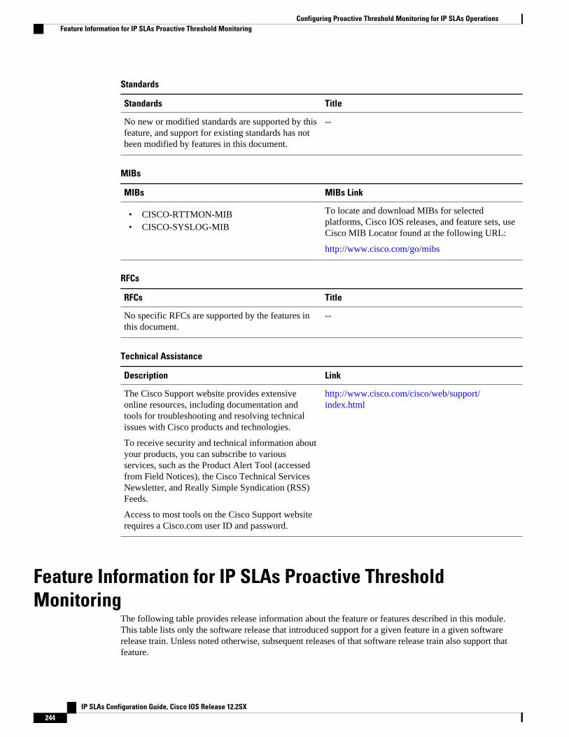
Standards
Standards Title
No new or modified standards are supported by thisfeature, and support for existing standards has notbeen modified by features in this document.
--
MIBs
MIBs MIBs Link
• CISCO-RTTMON-MIB• CISCO-SYSLOG-MIB
To locate and download MIBs for selectedplatforms, Cisco IOS releases, and feature sets, useCisco MIB Locator found at the following URL:
http://www.cisco.com/go/mibs
RFCs
RFCs Title
No specific RFCs are supported by the features inthis document.
--
Technical Assistance
Description Link
The Cisco Support website provides extensiveonline resources, including documentation andtools for troubleshooting and resolving technicalissues with Cisco products and technologies.
To receive security and technical information aboutyour products, you can subscribe to variousservices, such as the Product Alert Tool (accessedfrom Field Notices), the Cisco Technical ServicesNewsletter, and Really Simple Syndication (RSS)Feeds.
Access to most tools on the Cisco Support websiterequires a Cisco.com user ID and password.
http://www.cisco.com/cisco/web/support/index.html
Feature Information for IP SLAs Proactive ThresholdMonitoring
The following table provides release information about the feature or features described in this module.This table lists only the software release that introduced support for a given feature in a given softwarerelease train. Unless noted otherwise, subsequent releases of that software release train also support thatfeature.
Configuring Proactive Threshold Monitoring for IP SLAs Operations Feature Information for IP SLAs Proactive Threshold Monitoring
IP SLAs Configuration Guide, Cisco IOS Release 12.2SX244
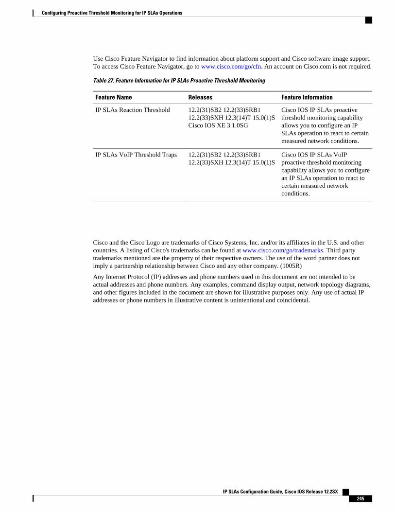
Use Cisco Feature Navigator to find information about platform support and Cisco software image support.To access Cisco Feature Navigator, go to www.cisco.com/go/cfn. An account on Cisco.com is not required.
Table 27: Feature Information for IP SLAs Proactive Threshold Monitoring
Feature Name Releases Feature Information
IP SLAs Reaction Threshold 12.2(31)SB2 12.2(33)SRB112.2(33)SXH 12.3(14)T 15.0(1)SCisco IOS XE 3.1.0SG
Cisco IOS IP SLAs proactivethreshold monitoring capabilityallows you to configure an IPSLAs operation to react to certainmeasured network conditions.
IP SLAs VoIP Threshold Traps 12.2(31)SB2 12.2(33)SRB112.2(33)SXH 12.3(14)T 15.0(1)S
Cisco IOS IP SLAs VoIPproactive threshold monitoringcapability allows you to configurean IP SLAs operation to react tocertain measured networkconditions.
Cisco and the Cisco Logo are trademarks of Cisco Systems, Inc. and/or its affiliates in the U.S. and othercountries. A listing of Cisco's trademarks can be found at www.cisco.com/go/trademarks. Third partytrademarks mentioned are the property of their respective owners. The use of the word partner does notimply a partnership relationship between Cisco and any other company. (1005R)
Any Internet Protocol (IP) addresses and phone numbers used in this document are not intended to beactual addresses and phone numbers. Any examples, command display output, network topology diagrams,and other figures included in the document are shown for illustrative purposes only. Any use of actual IPaddresses or phone numbers in illustrative content is unintentional and coincidental.
Configuring Proactive Threshold Monitoring for IP SLAs Operations
IP SLAs Configuration Guide, Cisco IOS Release 12.2SX 245

Example Triggering SNMP Notifications
IP SLAs Configuration Guide, Cisco IOS Release 12.2SX246