Embed Size (px)
Citation preview
IP Security Extensions forExplicit Congestion Control
Protocols
Nuno Goncalo de Castro Placido Salta
March 2008
Master’s Thesis in Electrical and Computer EngineeringINESC-Porto Supervisor: Filipe Lameiro Abrantes
FEUP Supervisor: Manuel Pereira Ricardo
(President of the Jury)

Abstract
This dissertation addresses the current interoperability limitations ofend-to-network protocols such as explicit congestion control protocols, withthe present IP security extensions, the IPsec. The current stack layout,with the IPsec appearing immediately after the IP network layer restrictsthe use of such congestion control protocols since the necessary informationto the middle nodes would appear inaccessible.
In this project, is made a discussion over design considerations and im-plementation details on altering IPsec in order to accommodate explicitcongestion control protocols such as XCP, eXplicit Control Protocol, with-out loss of functionality, thereby allowing congestion control to be per-formed securely in environments characterized by an erosion of trust.
The proposed implementation in based on the Information Sciences In-stitute’s XPC release and in the open source and highly acclaimed operatingsystem, the FreeBSD.

Contents
1 Introduction 1
1.1 Overview . . . . . . . . . . . . . . . . . . . . . . . . . . . . . 1
1.2 Objectives . . . . . . . . . . . . . . . . . . . . . . . . . . . . 2
1.3 Document Structure . . . . . . . . . . . . . . . . . . . . . . 2
2 Technical Background 3
2.1 IP Security . . . . . . . . . . . . . . . . . . . . . . . . . . . 3
2.1.1 IPsec operation . . . . . . . . . . . . . . . . . . . . . 3
2.1.2 Security Associations . . . . . . . . . . . . . . . . . . 4
2.1.3 Security Policy Database . . . . . . . . . . . . . . . . 5
2.1.4 IPsec Modes . . . . . . . . . . . . . . . . . . . . . . . 5
2.1.5 AH - Authentication Header . . . . . . . . . . . . . . 7
2.1.6 Encapsulating Security Payload . . . . . . . . . . . . 10
2.1.7 Mandatory and recommended cryptographic algorithms 12
2.2 XCP - eXplicit Control Protocol . . . . . . . . . . . . . . . . 14
2.2.1 Protocol Overview . . . . . . . . . . . . . . . . . . . 14
2.2.2 Congestion Header . . . . . . . . . . . . . . . . . . . 15
2.2.3 End-System Functions . . . . . . . . . . . . . . . . . 16
2.2.4 Router Functions . . . . . . . . . . . . . . . . . . . . 17
2.3 TCP/IP and IPsec implementation in FreeBSD . . . . . . . 20
2.3.1 Memory Buffers . . . . . . . . . . . . . . . . . . . . . 20
3 Integrating XCP with IPsec (IPv4) 25
3.1 Current scenario . . . . . . . . . . . . . . . . . . . . . . . . 27
3.1.1 IPsec and XCP packet flow . . . . . . . . . . . . . . 27
3.1.2 Current limitations and proposed solution . . . . . . 28
iii
iv CONTENTS
3.2 IPsec routines . . . . . . . . . . . . . . . . . . . . . . . . . . 30
3.2.1 Separating the congestion header from the IPsec pay-
load . . . . . . . . . . . . . . . . . . . . . . . . . . . 30
3.2.2 Inserting XCP before ESP . . . . . . . . . . . . . . . 31
3.2.3 Inserting XCP before AH . . . . . . . . . . . . . . . 33
3.3 Tunnel Mode . . . . . . . . . . . . . . . . . . . . . . . . . . 37
3.3.1 IPsec routines . . . . . . . . . . . . . . . . . . . . . . 37
3.3.2 TCP Output . . . . . . . . . . . . . . . . . . . . . . 38
4 Integrating XCP with IPsec (IPv6) 41
4.1 Current scenario . . . . . . . . . . . . . . . . . . . . . . . . 42
4.1.1 IPsec and XCP packet flow . . . . . . . . . . . . . . 42
4.1.2 Current limitations and proposed solution . . . . . . 44
4.2 IP Output routines . . . . . . . . . . . . . . . . . . . . . . . 45
4.2.1 Defining a new IPv6 Extension Header . . . . . . . . 45
4.2.2 Detecting and separating the XCP Header . . . . . . 45
4.3 IPsec routines . . . . . . . . . . . . . . . . . . . . . . . . . . 48
4.3.1 AH functions . . . . . . . . . . . . . . . . . . . . . . 48
4.4 IP Input routines . . . . . . . . . . . . . . . . . . . . . . . . 52
4.5 Tunnel mode . . . . . . . . . . . . . . . . . . . . . . . . . . 53
4.5.1 IP Output . . . . . . . . . . . . . . . . . . . . . . . . 53
4.5.2 TCP Output . . . . . . . . . . . . . . . . . . . . . . 54
5 Results 57
5.1 Testbed Setup . . . . . . . . . . . . . . . . . . . . . . . . . . 57
5.2 XCP with AH . . . . . . . . . . . . . . . . . . . . . . . . . . 58
5.3 XCP with ESP . . . . . . . . . . . . . . . . . . . . . . . . . 62
5.4 XCP with AH and ESP . . . . . . . . . . . . . . . . . . . . 66
5.5 XCP in tunnel mode . . . . . . . . . . . . . . . . . . . . . . 70
5.6 Performance Test . . . . . . . . . . . . . . . . . . . . . . . . 75
5.6.1 Data Rate . . . . . . . . . . . . . . . . . . . . . . . . 75
5.6.2 Packet Processing Time . . . . . . . . . . . . . . . . 76
6 Conclusion 79

CONTENTS v
A BSD License 81

List of Acronyms
AES Advanced Encryption Standard
AH Authentication Header
AIMD Additive Increase, Multiplicative Decrease
API Application Programming Interface
BSD Berkeley Software Distribution
CBC Cipher Block Chaining
DCCP Datagram Congestion Control Protocol
DES Data Encryption Standard
DNS Domain Name System
DNSSEC Domain Name System Security Extensions
DVB Digital Video Broadcasting
ECN Explicit Congestion Notification
ESP Encapsulating Security Protocol
FPGA Field-programmable Gate Array
HMAC Hash Message Authentication Code
ISI Information Sciences Institute, University of South California
IEEE Institute of Electrical and Electronics Engineers
IETF Internet Engineering Task Force
IP Internet Protocol
IPsec Internet Protocol Security Extensions
vii
viii List of Acronyms
IPv4 Internet Protocol Version 4
IPv6 Internet Protocol Version 6
LDAP Lightweight Directory Access Protocol
LSI Local Scope Identifier
MD5 Message-Digest algorithm 5
NAT Network Address Translation
RR Resource Record
RTT Round-trip Time
SA Security Association
SAD Security Association Database
SHA Secure Hash Algorithm
SPI Security Parameters Index
TCP Transmission Control Protocol
UDP User Datagram Protocol
UMTS Universal Mobile Telecommunications System
VPN Virtual Private Network
WLAN Wireless Local Area Network
XCP eXplicit Control Protocol
List of Figures
2.1 IPsec in Transport Mode . . . . . . . . . . . . . . . . . . . . 6
2.2 IPsec in Tunnel Mode . . . . . . . . . . . . . . . . . . . . . 6
2.3 AH in (a) transport mode and (b) tunnel mode. . . . . . . . 7
2.4 IPv4 (a) and IPv6 (b) headers, with highlighted fields pro-
tected by authentication. . . . . . . . . . . . . . . . . . . . . 8
2.5 AH header. . . . . . . . . . . . . . . . . . . . . . . . . . . . 9
2.6 ESP in (a) transport mode and (b) tunnel mode. . . . . . . 10
2.7 ESP Header and Trailer. . . . . . . . . . . . . . . . . . . . . 11
2.8 XCP flow path with corresponding feedback. . . . . . . . . . 15
2.9 XCP congestion header, version 2. . . . . . . . . . . . . . . . 15
2.10 MBUF types . . . . . . . . . . . . . . . . . . . . . . . . . . 22
3.1 Current XCP authentication and encryption. . . . . . . . . . 26
3.2 Function calls for outgoing and incoming IPv4 packets . . . 27
3.3 Modified IPsec processing of XCP header. . . . . . . . . . . 31
3.4 Congestion header being interpreted as ESP header. . . . . . 32
3.5 Current input processing of XCP/AH packets. . . . . . . . . 34
3.6 Tunneling XCP packets. . . . . . . . . . . . . . . . . . . . . 37
4.1 Function calls for outgoing and incoming IPv4 packets . . . 42
4.2 XCP header separated from the payload . . . . . . . . . . . 47
4.3 ola . . . . . . . . . . . . . . . . . . . . . . . . . . . . . . . . 50
4.4 Correct input processing of XCP/AH packets . . . . . . . . 51
5.1 XCP/IPSec testbed . . . . . . . . . . . . . . . . . . . . . . . 58
ix

List of Tables
2.1 Services provided by ESP and AH. . . . . . . . . . . . . . . 4
2.2 Most important TCP/IP and IPsec source files . . . . . . . . 21
2.3 MBUF macros . . . . . . . . . . . . . . . . . . . . . . . . . . 23
2.4 MBUF functions . . . . . . . . . . . . . . . . . . . . . . . . 24
5.1 Establishment of TCP/IPv4 session with XCP and AH. . . . 60
5.2 Establishment of TCP/IPv6 session with XCP and AH. . . . 61
5.3 Establishment of TCP/IPv4 session with XCP and ESP. . . 63
5.4 Establishment of TCP/IPv6 session with XCP and ESP. . . 63
5.5 Establishment of TCP/IPv4 session with XCP, AH and ESP. 67
5.6 Establishment of TCP/IPv6 session with XCP, AH and ESP. 68
5.7 Establishment of TCP/IPv4 session with XCP in tunnel mode. 71
5.8 IPv6: Establishment of TCP/IPv6 session with XCP in tun-
nel mode. . . . . . . . . . . . . . . . . . . . . . . . . . . . . 72
5.9 Average data rate for the several IPsec scenarios in IPv4. . . 75
5.10 Average data rate for the several IPsec scenarios in IPv6. . . 75
5.11 Average processing time for the several IPsec scenarios in
IPv4. . . . . . . . . . . . . . . . . . . . . . . . . . . . . . . . 76
5.12 Average processing time for the several IPsec scenarios in
IPv6. . . . . . . . . . . . . . . . . . . . . . . . . . . . . . . . 76
xi

Auxiliary Listings
2.1 Security Association database entry. . . . . . . . . . . . . . . 5
2.2 Security Association database entry. . . . . . . . . . . . . . . 5
3.1 netinet6/ipsec.c detection and split of XCP header . . . . . 30
3.2 netinet6/esp output.c skiping XCP header . . . . . . . . . . 32
3.3 netinet6/ah output.c skiping XCP header . . . . . . . . . . . 33
3.4 netinet6/ah core.c correcting IP header . . . . . . . . . . . . 35
3.5 netinet6/ah core.c Tag detection and XCP authentication
support . . . . . . . . . . . . . . . . . . . . . . . . . . . . . 35
3.6 netinet6/esp input.c Tag detection and XCP authentication
support . . . . . . . . . . . . . . . . . . . . . . . . . . . . . 38
3.7 netinet6/tcp output.c maximum segment size . . . . . . . . . 38
4.1 netinet6/ip6 output.c additional IPv6 extension header . . . 45
4.2 netinet6/ip6 output.c detection of XCP header . . . . . . . . 45
4.3 netinet6/ip6 output.c separation of XCP header . . . . . . . 46
4.4 netinet6/ah core.c protecting XCP header immutable fields . 49
4.5 netinet6/ah core.c searching for XCP Tag and checking the
header . . . . . . . . . . . . . . . . . . . . . . . . . . . . . . 50
4.6 netinet6/ip6 input.c support for the XCP header to the ip6 nexthdr
function . . . . . . . . . . . . . . . . . . . . . . . . . . . . . 52
4.7 netinet6/ip6 output.c copy the XCP header to a temporary
MBUF . . . . . . . . . . . . . . . . . . . . . . . . . . . . . . 53
4.8 netinet6/ip6 output.c add the XCP header MBUF to the
packet chain . . . . . . . . . . . . . . . . . . . . . . . . . . . 54
4.9 netinet6/tcp output.c maximum segment size . . . . . . . . . 54
5.1 Client security policy with AH for IPv4. . . . . . . . . . . . 58
5.2 Server security policy with AH for IPv4. . . . . . . . . . . . 58
xiii
xiv AUXILIARY LISTINGS
5.3 Client security policy with AH for IPv6. . . . . . . . . . . . 59
5.4 Server security policy with AH for IPv6. . . . . . . . . . . . 59
5.5 Overview of resulting XCP/AH IPv4 packet. . . . . . . . . . 59
5.6 Overview of resulting XCP/AH IPv6 packet. . . . . . . . . . 60
5.7 Client security policy with ESP for IPv4. . . . . . . . . . . . 62
5.8 Server security policy with ESP for IPv4. . . . . . . . . . . . 62
5.9 Client security policy with ESP for IPv6. . . . . . . . . . . . 62
5.10 Server security policy with ESP for IPv6. . . . . . . . . . . . 62
5.11 Overview of resulting XCP/ESP IPv4 packet. . . . . . . . . 64
5.12 Overview of resulting XCP/ESP IPv6 packet. . . . . . . . . 64
5.13 Client security policy with AH and ESP for IPv4. . . . . . . 66
5.14 Server security policy with AH and ESP for IPv4. . . . . . . 66
5.15 Client security policy with AH and ESP for IPv6. . . . . . . 66
5.16 Server security policy with AH and ESP for IPv6. . . . . . . 67
5.17 Overview of resulting XCP/AH/ESP IPv4 packet. . . . . . . 67
5.18 Overview of resulting XCP/AH/ESP IPv6 packet. . . . . . . 69
5.19 Client security policy with tunnel mode encryption for IPv4. 70
5.20 Server security policy with tunnel mode encryption for IPv4. 70
5.21 Client security policy with tunnel mode encryption for IPv6. 70
5.22 Server security policy with tunnel mode encryption for IPv6. 71
5.23 Overview of resulting XCP IPv4 packet in tunnel mode. . . 72
5.24 Overview of resulting XCP IPv6 packet in tunnel mode. . . 73
Chapter 1
Introduction
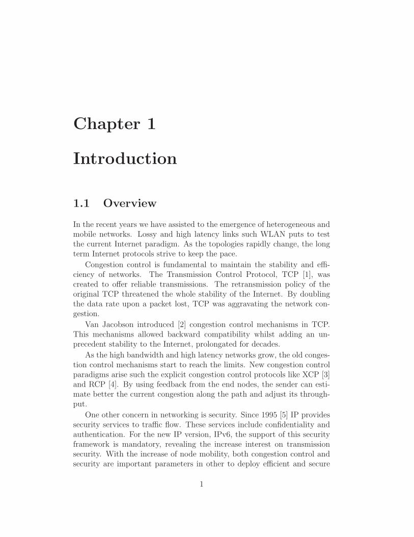
1.1 Overview
In the recent years we have assisted to the emergence of heterogeneous andmobile networks. Lossy and high latency links such WLAN puts to testthe current Internet paradigm. As the topologies rapidly change, the longterm Internet protocols strive to keep the pace.
Congestion control is fundamental to maintain the stability and effi-ciency of networks. The Transmission Control Protocol, TCP [1], wascreated to offer reliable transmissions. The retransmission policy of theoriginal TCP threatened the whole stability of the Internet. By doublingthe data rate upon a packet lost, TCP was aggravating the network con-gestion.
Van Jacobson introduced [2] congestion control mechanisms in TCP.This mechanisms allowed backward compatibility whilst adding an un-precedent stability to the Internet, prolongated for decades.
As the high bandwidth and high latency networks grow, the old conges-tion control mechanisms start to reach the limits. New congestion controlparadigms arise such the explicit congestion control protocols like XCP [3]and RCP [4]. By using feedback from the end nodes, the sender can esti-mate better the current congestion along the path and adjust its through-put.
One other concern in networking is security. Since 1995 [5] IP providessecurity services to traffic flow. These services include confidentiality andauthentication. For the new IP version, IPv6, the support of this securityframework is mandatory, revealing the increase interest on transmissionsecurity. With the increase of node mobility, both congestion control andsecurity are important parameters in other to deploy efficient and secure
1
2 Chapter 1. Introduction
networks. The interoperability of both should be a matter of interest.
1.2 Objectives
The goal of this project is to integrate a new breed of congestion controlmechanisms into the standard IP Security Extensions, IPsec. Having iden-tified key requirements and currently unsolved issues in the interoperabilitybetween congestion control protocols, the objectives span features in aidingthe future standardization and deployment of congestion control protocols,namely:
– FreeBSD stack review Gain knowledge of the current TCP/IPstack implementation. Identify and understand the several functionsthat comprise the Transport and Network layers as well as the IPsecfunction. Also take into account the code convention and best prac-tices.
– IPsec restrictions Locate the current limitations in the IPsec rou-tines and elaborate a solution to overcome those restrictions to allowthe integration of XCP within IPsec.
– XCP (eXplicit Control Protocol) integration Deploy the pro-posed solution for both IP versions and validate through testing theseveral IPsec services.
1.3 Document Structure
The outline of this dissertation is as follow: chapter 2 makes a review ofthe current IP security extension and the eXplicit Control Potrocol. Alsois done some insight into FreeBSD TCP/IP implementation. Chapters 3and 4 cover the proposed XCP integration with IPsec. Chapter 3 makesa detailed description on the implementation in IPv4 whilst the chapter 5describes the implementation for IPv6. The chapter 5 covers the resultsobtained in the use of the implementation showing several scenarios forthe diverse possible combinations of the IP Security servicies. Finally, theChapter 6 makes conclusions upon the work validation and the obtainedresults.
Chapter 2
Technical Background
2.1 IP Security
IPSec [6] is a Security Architecture for the Internet Protocol developed bythe IETF to offer interoperable security services at the IP network layer,both IPv4 and IPv6 and thus enclosing all the upper layers. The standardwas initial specified in 1995 [5] and was updated and extended ever since.
The IPsec does not define specific functionalities and algorithms but in-stead provides a flexible framework to allow extensible integration of newdevelopments. IPsec addresses critical security concerns such as authenti-cation, confidentiality, data integrity and anti-replay protection. Allowingendpoints to negotiate asymmetrically the use of algorithms and associatedparameters enables IPsec to be scalable and meet the user requirements,while interoperability between legacy equipment is guaranteed through thespecification of a minimal set of encryption algorithms that all IPsec im-plementations must recognize.
These factors, allied to standardization, contributed to the widespreaddeployment of IPsec, rapidly becoming the defacto network layer securitysolution, especially on VPN tunnels.
The support of the IPsec protocol suite is mandatory on the IPv6 im-plementation.
2.1.1 IPsec operation
The IPsec functionalities relies on two main protocols: the Authentica-tion Header (AH) [7] and Encapsulating Security Payload (ESP)[8]. Both protocols are described in their respective RFC and they are per-formed on IP packets in order to provide data confidentiality and authen-tication. The support on the IPsec implementation of ESP is mandatory
3
4 Chapter 2. Technical Background
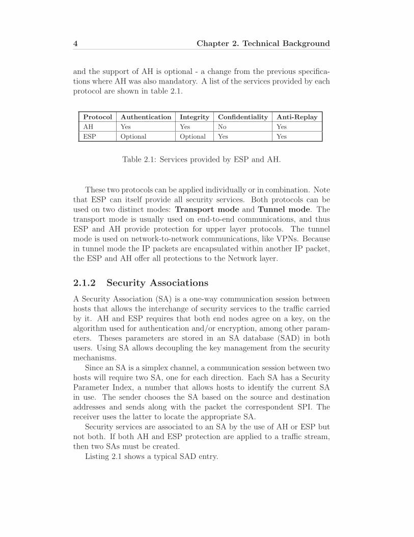
and the support of AH is optional - a change from the previous specifica-tions where AH was also mandatory. A list of the services provided by eachprotocol are shown in table 2.1.
Protocol Authentication Integrity Confidentiality Anti-Replay
AH Yes Yes No Yes
ESP Optional Optional Yes Yes
Table 2.1: Services provided by ESP and AH.
These two protocols can be applied individually or in combination. Notethat ESP can itself provide all security services. Both protocols can beused on two distinct modes: Transport mode and Tunnel mode. Thetransport mode is usually used on end-to-end communications, and thusESP and AH provide protection for upper layer protocols. The tunnelmode is used on network-to-network communications, like VPNs. Becausein tunnel mode the IP packets are encapsulated within another IP packet,the ESP and AH offer all protections to the Network layer.
2.1.2 Security Associations
A Security Association (SA) is a one-way communication session betweenhosts that allows the interchange of security services to the traffic carriedby it. AH and ESP requires that both end nodes agree on a key, on thealgorithm used for authentication and/or encryption, among other param-eters. Theses parameters are stored in an SA database (SAD) in bothusers. Using SA allows decoupling the key management from the securitymechanisms.
Since an SA is a simplex channel, a communication session between twohosts will require two SA, one for each direction. Each SA has a SecurityParameter Index, a number that allows hosts to identify the current SAin use. The sender chooses the SA based on the source and destinationaddresses and sends along with the packet the correspondent SPI. Thereceiver uses the latter to locate the appropriate SA.
Security services are associated to an SA by the use of AH or ESP butnot both. If both AH and ESP protection are applied to a traffic stream,then two SAs must be created.
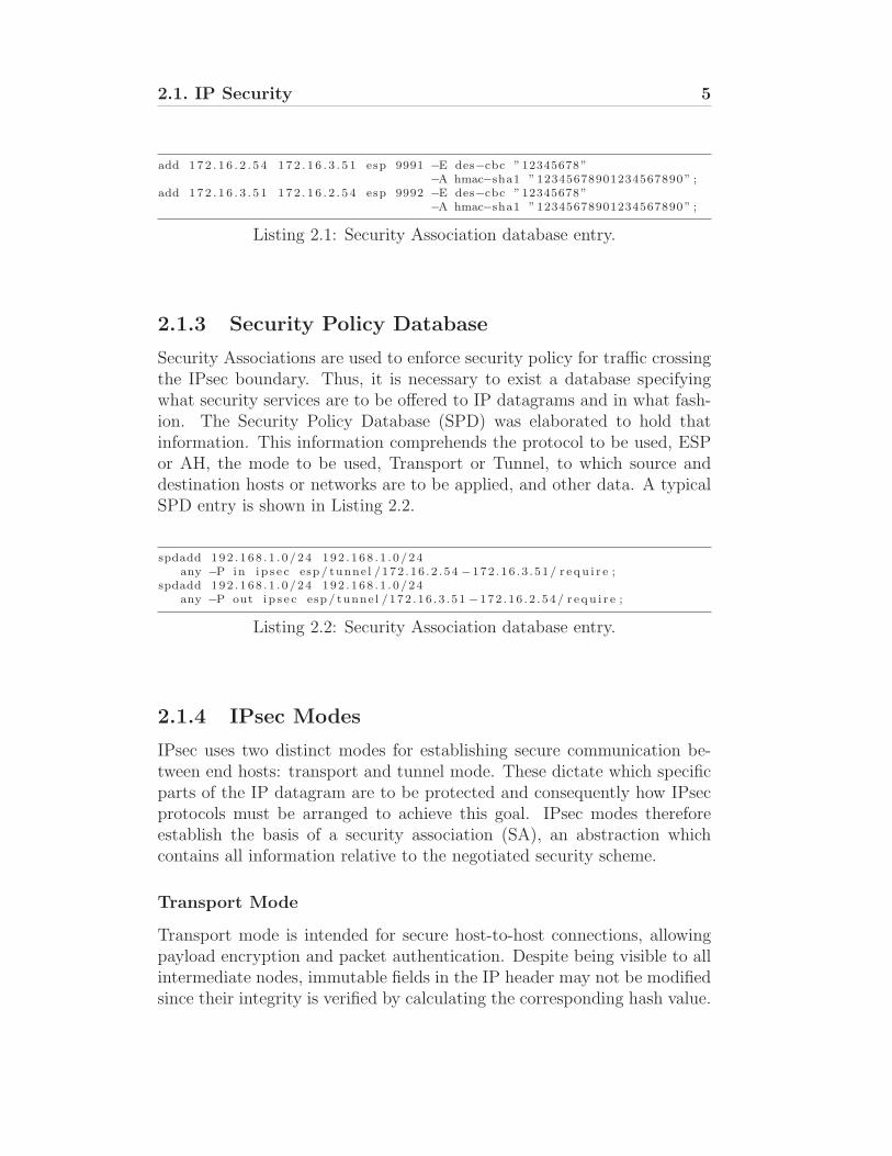
Listing 2.1 shows a typical SAD entry.
2.1. IP Security 5
add 172 . 1 6 . 2 . 5 4 172 . 1 6 . 3 . 5 1 esp 9991 −E des−cbc ”12345678”−A hmac−sha1 ”12345678901234567890” ;
add 172 . 1 6 . 3 . 5 1 172 . 1 6 . 2 . 5 4 esp 9992 −E des−cbc ”12345678”−A hmac−sha1 ”12345678901234567890” ;
Listing 2.1: Security Association database entry.
2.1.3 Security Policy Database
Security Associations are used to enforce security policy for traffic crossingthe IPsec boundary. Thus, it is necessary to exist a database specifyingwhat security services are to be offered to IP datagrams and in what fash-ion. The Security Policy Database (SPD) was elaborated to hold thatinformation. This information comprehends the protocol to be used, ESPor AH, the mode to be used, Transport or Tunnel, to which source anddestination hosts or networks are to be applied, and other data. A typicalSPD entry is shown in Listing 2.2.
spdadd 192 . 168 . 1 . 0/24 192 . 168 . 1 . 0/24any −P in i p s e c esp / tunne l /172 .16 . 2 . 54 −172 .16 . 3 . 51/ r e qu i r e ;
spdadd 192 . 168 . 1 . 0/24 192 . 168 . 1 . 0/24any −P out i p s e c esp / tunne l /172 .16 . 3 . 51 −172 .16 . 2 . 54/ r e qu i r e ;
Listing 2.2: Security Association database entry.
2.1.4 IPsec Modes
IPsec uses two distinct modes for establishing secure communication be-tween end hosts: transport and tunnel mode. These dictate which specificparts of the IP datagram are to be protected and consequently how IPsecprotocols must be arranged to achieve this goal. IPsec modes thereforeestablish the basis of a security association (SA), an abstraction whichcontains all information relative to the negotiated security scheme.
Transport Mode
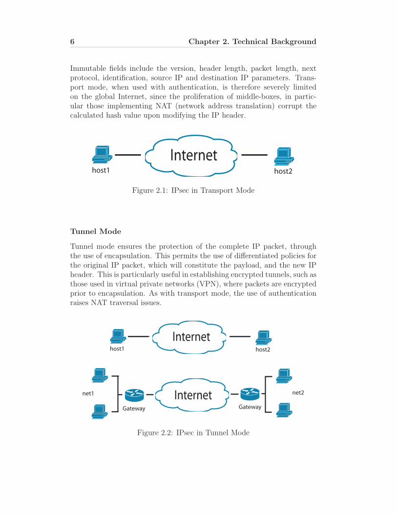
Transport mode is intended for secure host-to-host connections, allowingpayload encryption and packet authentication. Despite being visible to allintermediate nodes, immutable fields in the IP header may not be modifiedsince their integrity is verified by calculating the corresponding hash value.
6 Chapter 2. Technical Background
Immutable fields include the version, header length, packet length, nextprotocol, identification, source IP and destination IP parameters. Trans-port mode, when used with authentication, is therefore severely limitedon the global Internet, since the proliferation of middle-boxes, in partic-ular those implementing NAT (network address translation) corrupt thecalculated hash value upon modifying the IP header.
host1 host2
Internet
Figure 2.1: IPsec in Transport Mode
Tunnel Mode
Tunnel mode ensures the protection of the complete IP packet, throughthe use of encapsulation. This permits the use of differentiated policies forthe original IP packet, which will constitute the payload, and the new IPheader. This is particularly useful in establishing encrypted tunnels, such asthose used in virtual private networks (VPN), where packets are encryptedprior to encapsulation. As with transport mode, the use of authenticationraises NAT traversal issues.
host1 host2
Internet
InternetGateway Gateway
net1 net2
Figure 2.2: IPsec in Tunnel Mode
2.1. IP Security 7
In tunnel mode however, authentication of the outer header may be aless pressing concern since the protection of the original packet is assured.As such, tunnel mode is particularly well suited for network-to-network andhost-to-network connections.
2.1.5 AH - Authentication Header
IP AHHeader Header
Payload
(a)
Outer IP AH Inner IPHeader Header Header
Payload
(b)
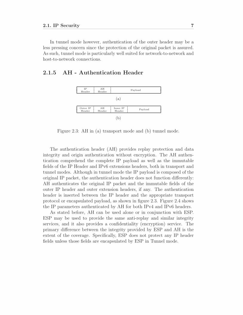
Figure 2.3: AH in (a) transport mode and (b) tunnel mode.
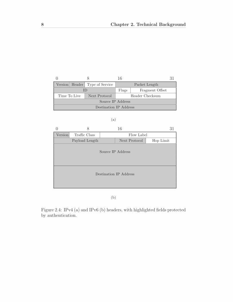
The authentication header (AH) provides replay protection and dataintegrity and origin authentication without encryption. The AH authen-tication comprehend the complete IP payload as well as the immutablefields of the IP Header and IPv6 extensions headers, both in transport andtunnel modes. Although in tunnel mode the IP payload is composed of theoriginal IP packet, the authentication header does not function differently:AH authenticates the original IP packet and the immutable fields of theouter IP header and outer extension headers, if any. The authenticationheader is inserted between the IP header and the appropriate transportprotocol or encapsulated payload, as shown in figure 2.3. Figure 2.4 showsthe IP parameters authenticated by AH for both IPv4 and IPv6 headers.
As stated before, AH can be used alone or in conjunction with ESP.ESP may be used to provide the same anti-replay and similar integrityservices, and it also provides a confidentiality (encryption) service. Theprimary difference between the integrity provided by ESP and AH is theextent of the coverage. Specifically, ESP does not protect any IP headerfields unless those fields are encapsulated by ESP in Tunnel mode.
8 Chapter 2. Technical Background
0 8 16 31
Version Header Type of Service Packet Length
ID Flags Fragment Offset
Time To Live Next Protocol Header Checksum
Source IP Address
Destination IP Address
(a)
0 8 16 31
Version Traffic Class Flow Label
Payload Length Next Protocol Hop Limit
Source IP Address
Destination IP Address
(b)
Figure 2.4: IPv4 (a) and IPv6 (b) headers, with highlighted fields protectedby authentication.
2.1. IP Security 9
AH Format
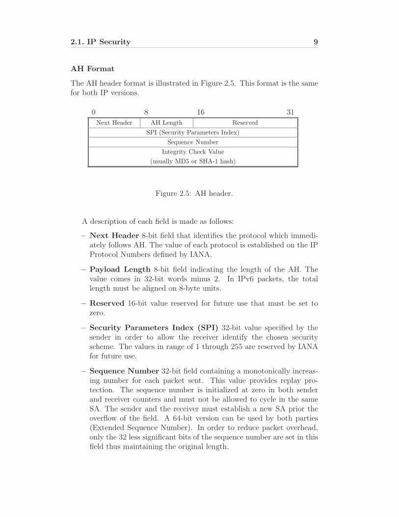
The AH header format is illustrated in Figure 2.5. This format is the samefor both IP versions.
0 8 16 31
Next Header AH Length Reserved
SPI (Security Parameters Index)
Sequence Number
Integrity Check Value
(usually MD5 or SHA-1 hash)
Figure 2.5: AH header.
A description of each field is made as follows:
– Next Header 8-bit field that identifies the protocol which immedi-ately follows AH. The value of each protocol is established on the IPProtocol Numbers defined by IANA.
– Payload Length 8-bit field indicating the length of the AH. Thevalue comes in 32-bit words minus 2. In IPv6 packets, the totallength must be aligned on 8-byte units.
– Reserved 16-bit value reserved for future use that must be set tozero.
– Security Parameters Index (SPI) 32-bit value specified by thesender in order to allow the receiver identify the chosen securityscheme. The values in range of 1 through 255 are reserved by IANAfor future use.
– Sequence Number 32-bit field containing a monotonically increas-ing number for each packet sent. This value provides replay pro-tection. The sequence number is initialized at zero in both senderand receiver counters and must not be allowed to cycle in the sameSA. The sender and the receiver must establish a new SA prior theoverflow of the field. A 64-bit version can be used by both parties(Extended Sequence Number). In order to reduce packet overhead,only the 32 less significant bits of the sequence number are set in thisfield thus maintaining the original length.
10 Chapter 2. Technical Background
– Integrity Check Value (ICV) This is a variable-length field con-taining computed authentication signature. The field must be a mul-tiple of 32-bit and may contain pad bits in order to the AH be alignedto 64-bit for IPv6 packets.
Calculating the Integrity Check Value
ICV is obtained by applying an integrity algorithm upon the packet. Thesealgorithms include Message Authentication Codes (MACs) based on sym-metric encryption algorithms like AES[U.S. FIPS PUB 197] or one wayhash functions like MD5, SHA-1, SHA-256 and others.
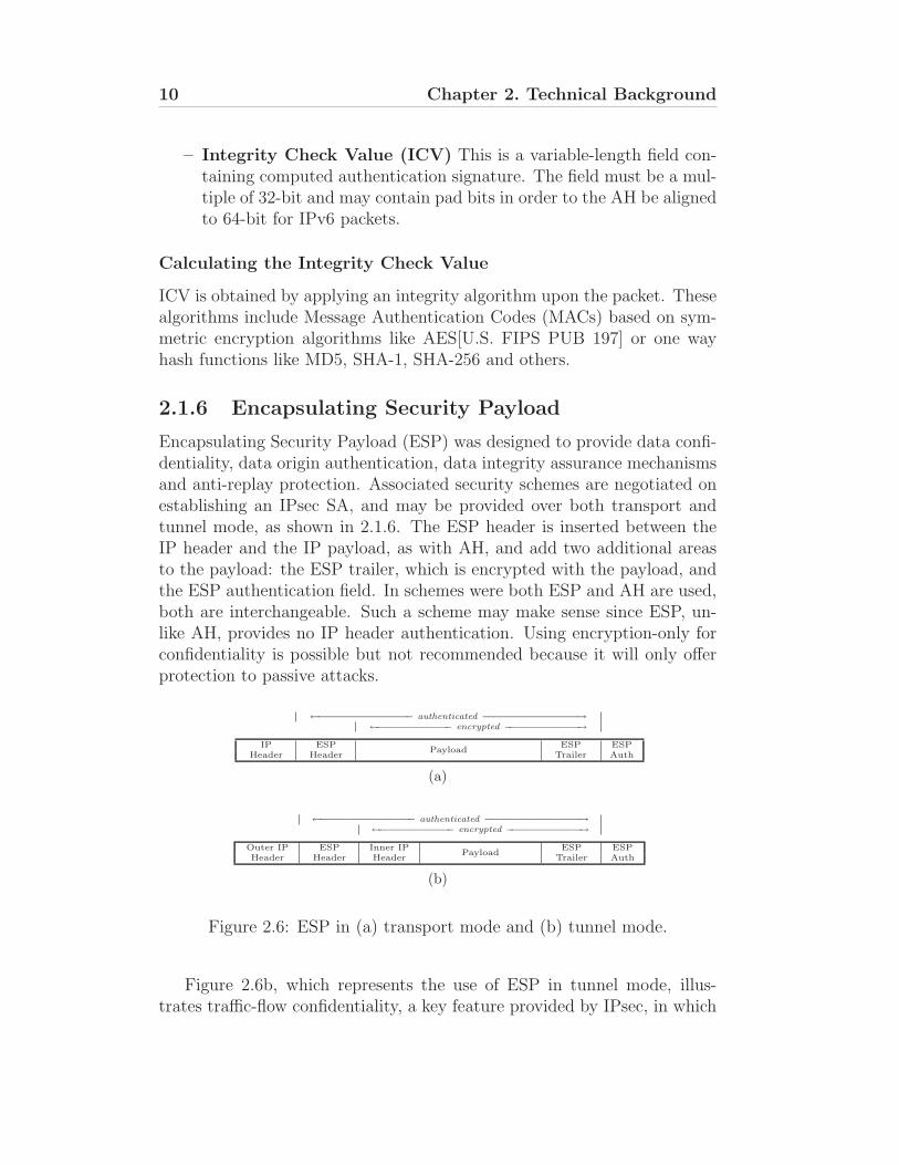
2.1.6 Encapsulating Security Payload
Encapsulating Security Payload (ESP) was designed to provide data confi-dentiality, data origin authentication, data integrity assurance mechanismsand anti-replay protection. Associated security schemes are negotiated onestablishing an IPsec SA, and may be provided over both transport andtunnel mode, as shown in 2.1.6. The ESP header is inserted between theIP header and the IP payload, as with AH, and add two additional areasto the payload: the ESP trailer, which is encrypted with the payload, andthe ESP authentication field. In schemes were both ESP and AH are used,both are interchangeable. Such a scheme may make sense since ESP, un-like AH, provides no IP header authentication. Using encryption-only forconfidentiality is possible but not recommended because it will only offerprotection to passive attacks.
←−−−−−−−−−−−−−−−− authenticated −−−−−−−−−−−−−−−−→
←−−−−−−−−−−−−− encrypted −−−−−−−−−−−−−→
IP ESPPayload
ESP ESPHeader Header Trailer Auth
(a)
←−−−−−−−−−−−−−−−− authenticated −−−−−−−−−−−−−−−−→
←−−−−−−−−−−−−− encrypted −−−−−−−−−−−−−→
Outer IP ESP Inner IPPayload
ESP ESPHeader Header Header Trailer Auth
(b)
Figure 2.6: ESP in (a) transport mode and (b) tunnel mode.
Figure 2.6b, which represents the use of ESP in tunnel mode, illus-trates traffic-flow confidentiality, a key feature provided by IPsec, in which
2.1. IP Security 11
packet encryption and subsequent encapsulation provides complete privacy.Encryption is provided using symmetric-key algorithms such as DES [9],3DES [10] and AES [11]. ESP allows data authentication based on a Keyed-HMAC (hash message authentication code) included in the ESP header.The HMAC is calculated using authentication algorithms supported byIPsec, such as MD5 [12] and SHA-1 [13].
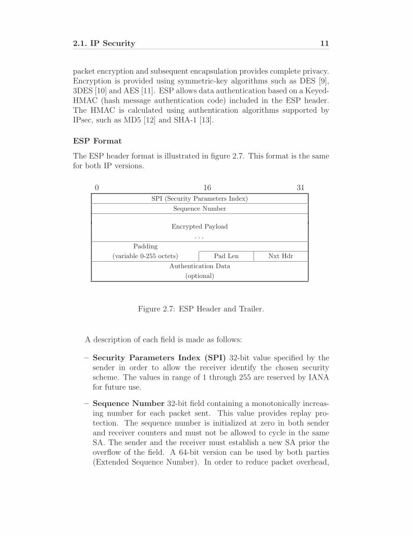
ESP Format
The ESP header format is illustrated in figure 2.7. This format is the samefor both IP versions.
0 16 31
SPI (Security Parameters Index)
Sequence Number
Encrypted Payload
. . .Padding
(variable 0-255 octets) Pad Len Nxt Hdr
Authentication Data
(optional)
Figure 2.7: ESP Header and Trailer.
A description of each field is made as follows:
– Security Parameters Index (SPI) 32-bit value specified by thesender in order to allow the receiver identify the chosen securityscheme. The values in range of 1 through 255 are reserved by IANAfor future use.
– Sequence Number 32-bit field containing a monotonically increas-ing number for each packet sent. This value provides replay pro-tection. The sequence number is initialized at zero in both senderand receiver counters and must not be allowed to cycle in the sameSA. The sender and the receiver must establish a new SA prior theoverflow of the field. A 64-bit version can be used by both parties(Extended Sequence Number). In order to reduce packet overhead,
12 Chapter 2. Technical Background
only the 32 less significant bits of the sequence number are set in thisfield thus maintaining the original length.
– Encrypted Payload is a variable-length field containing data (fromthe original IP packet) described by the Next Header field. ThePayload Data field is mandatory and is an integral number of bytesin length. Note that the beginning of the next layer protocol headermust be aligned relative to the beginning of the ESP header as follows.For IPv4, this alignment is a multiple of 4 bytes. For IPv6, thealignment is a multiple of 8 bytes.
– Padding This field fills to purposes: If an encryption algorithm isemployed that requires the plaintext to be a multiple of some numberof bytes the Padding field is used to fill the plaintext (consisting ofthe Payload Data, Padding, Pad Length, and Next Header fields) tothe size required by the algorithm; Padding also may be required,irrespective of encryption algorithm requirements, to ensure that theresulting ciphertext terminates on a 4-byte boundary. Specifically,the Pad Length and Next Header fields must be right aligned within a4-byte word, as illustrated in the ESP packet format figures above, toensure that the ICV field (if present) is aligned on a 4-byte boundary.
– Pad Length The Pad Length field indicates the number of pad bytesimmediately preceding it in the Padding field. The range of validvalues is 0 to 255, where a value of zero indicates that no Paddingbytes are present. The Pad Length field is mandatory.
– Next Header 8-bit field that identifies the protocol which immedi-ately follows AH. The value of each protocol is established on the IPProtocol Numbers defined by IANA.
– Integrity Check Value (ICV) This is a variable-length field con-taining computed authentication signature. The field must be a mul-tiple of 32-bit and may contain pad bits in order to the AH be alignedto 64-bit for IPv6 packets.
2.1.7 Mandatory and recommended cryptographic al-gorithms
In order to guarantee interoperability between distinct implementations ofthe IPSec, some mandatory-to-support algorithms were specified [RFC4305].Optional but recommended algorithms were also specified.
2.1. IP Security 13
ESP encryption algorithms
Mandatory
– NULL Algorithm
– TripleDES-CBC
Recommended
– AES-CBC with 128-bit keys
– AES-CTR
ESP authentication algorithms
Mandatory
– HMAC-SHA1-96
– NULL Algorithm
Recommended
– AES-XCBC-MAC-96
– HMAC-MD5-96
Note that NULL algorithm in practice does not actually encrypts orauthenticates data. One of the uses of the Null algorithm is for debugpurposes.
AH authentication algorithms
Mandatory
– HMAC-SHA1-96
Recommended
– AES-XCBC-MAC-96
– HMAC-MD5-96
14 Chapter 2. Technical Background
2.2 XCP - eXplicit Control Protocol
TCP is the standard end-to-end transport protocol of the Internet. Thecongestion control mechanisms introduced by the former are fundamentalto maintain an high performance and stable network operation. As theInternet evolves and the high bandwidth and latency networks rise likeGigabit links and lossy wireless links, the current TCP congestion con-trol algorithms begun to reach its limits, since TCP reacts adversely toincreases in bandwidth or delay. Also, the growth of real-time distribu-tions, introduces other transport protocols that contribute to the networkcongestion.
Since TCP has no explicit feedback from the network, TCP is limitedto estimate congestion from packet loss. TCP responds conservatively topacket losses because of the AIMD (additive increase, multiplicative de-crease) paradigm of the control algorithms. This scenario is not suited forlossy wireless technologies like UMTS, WLAN, DVB and Bluetooth, sincethe decrease policy is aggressive while the increase policy is conservative.A new approach is necessary to maintain the stability and optimization ofthe Internet.
2.2.1 Protocol Overview
The introduction of explicit congestion control protocols like the eXplicitControl Protocol represents a major advance in Internet congestion control.XCP can deliver the highest possible application performance in extremelyhigh speed and high latency network links that TCP does not operatewell. Doing so, XCP achieves maximum link utilization without bandwidthwastes due packet loss.
XCP foresee three types of participants: the sender hosts, the receiverhosts, and the intermediate nodes in which packet queuing occurs (typicallyrouters). The senders specify their desired throughput in the outgoingpackets and routers along the path adjust the value to reflect both fairnessand available bandwidth. At the end of the path, the receiver will sendback the value of the resulting throughput and the sender will adjust itscongestion windows accordingly.
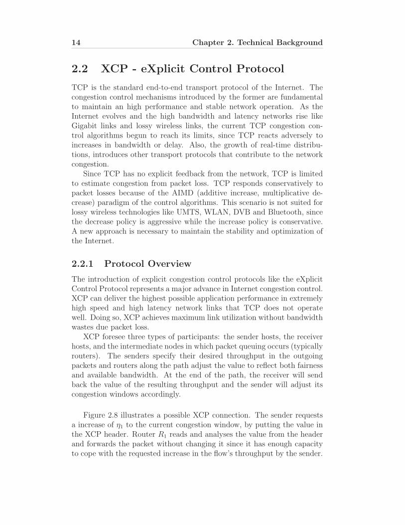
Figure 2.8 illustrates a possible XCP connection. The sender requestsa increase of η1 to the current congestion window, by putting the value inthe XCP header. Router R1 reads and analyses the value from the headerand forwards the packet without changing it since it has enough capacityto cope with the requested increase in the flow’s throughput by the sender.
2.2. XCP - eXplicit Control Protocol 15
+η₁ +η₂+η₁
feedback: +η₂
R₁ R₂
Receiver
Figure 2.8: XCP flow path with corresponding feedback.
On the other hand, Router R2 has no enough bandwith to answer to therequested value and replaces η1 by a lower value, η2, the throughput thatR2 can afford to spare to the flow. Finally, the receiver copies the finalvalue, η2 and sends it back to the origin as feedback. The original senderreads the resulting value and adjusts his congestion window accordingly.
2.2.2 Congestion Header
0 8 16 31
Protocol Length Version Format Unused
RTT
X
Delta Throughput
Reverse Feedback
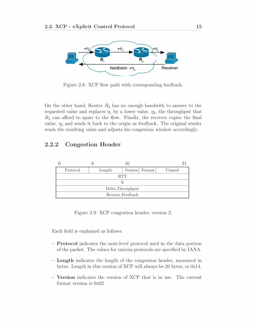
Figure 2.9: XCP congestion header, version 2.
Each field is explained as follows:
– Protocol indicates the next-level protocol used in the data portionof the packet. The values for various protocols are specified by IANA.
– Length indicates the length of the congestion header, measured inbytes. Length in this version of XCP will always be 20 bytes, or 0x14.
– Version indicates the version of XCP that is in use. The currentformat version is 0x02.
16 Chapter 2. Technical Background
– Format indicates header format. Currently only the Standard For-mat and Minimal Format are defined.
– unused This field is unused and must be set to zero in the currentversion of XCP.
– RTT indicates the round-trip time measured by the sender, in fixedpoint format with 28 bits after the binary point, in seconds. Thisfield is not used in Minimal Format.
– X indicates the inter-packet time of the flow as calculated by thesender, in fixed point format with 28 bits after the binary point, inseconds. This is the same format as used by the RTT field. Also notused in the Minimal Format.
– Delta Throughput indicates the desired or allocated change inthroughput. It is set by the sender to indicate the amount by whichthe sender would like to adjust its throughput, and it may be subse-quently reduced by routers along the path. Also not used in MinimalFormat.
– Reverse Feedback indicates the value of Delta Throughput receivedby the data receiver. The receiver copies the field Delta Throughputinto the Reverse Feedback field of the next outgoing packet in thesame flow.
A more recent XCP draft specifies a rearrangement to the CongestionHeader fields in order to optimize performance on FCPGA implementation.However, only the version 2 is avaiable at ISI’s XCP website.
2.2.3 End-System Functions
The sender must signal desired changes in throughput by calculating theappropriate Delta Throughput value. This value reflects the per-packetdistribution of the throughput change and is required in order to maintainXCP routers oblivious to per-flow congestion states. Delta Throughput isobtained by calculating the difference between the desired and estimatedthroughput, which represents the appropriate change, and dividing theresult by the number of packets in one round-trip time. The latter may beestimated by dividing the current throughput by the maximum segmentsize, thus obtaining an estimate for the current throughput in packets,and multiplying the resulting value by the round-trip time. The resultingequation is shown below (2.1):
2.2. XCP - eXplicit Control Protocol 17
Delta Throughput =tp − ta
ta ·(
RTTMSS
) (2.1)
where tp is the desired throughput, ta is the current throughput, RTT isthe current round-trip time estimate and MSS is the maximum segmentsize of outgoing packets. Additionally, the sender must set their currentestimate of both RTT and X, the inter-packet time. X may be estimatedby dividing the round-trip time by the number of outstanding packets or,alternatively, by obtaining the ratio between packet size and the currentthroughput.
The receiver simply copies the received Delta Throughput value intothe Reverse Feedback field of outgoing packets, thus bringing closure to thesystem’s feedback loop.
Upon receiving the feedback value, the sender adjusts it’s output rateaccordingly. Under TCP, this adjustment is achieved by modulating thecongestion window, cwnd, as described by equation (2.2):
cwnd = max (cwnd + Reverse Feedback · RTT,MSS) (2.2)
A minimum value of MSS is required to avoid the ”Silly Window Syn-drome” [14].
2.2.4 Router Functions
Despite being an integral part of XCP end hosts perform few functions:the sender requests a change in throughput, while receivers merely returnthe resulting throughput as feedback. The core of XCP lies in the routers,where the de-coupling of utilization control from fairness control allows thesystem to converge to optimal efficiency.
Packet Arrival
On arrival at a router, the data contained in the packet’s congestion headeris used to update parameters used for further calculations. The router mustupdate the total amount of incoming data, input traffic, by incrementingthe current value with the incoming packet’s size in bytes. Additionally, therouter must maintain an accurate estimate of the average RTT, d, acrossall flows, without maintaining per-flow state. This is achieved using (2.3):
d =
∑
(X · RTT )∑
X(2.3)
18 Chapter 2. Technical Background
Consequently, the router must maintain both the summed total of incomingvalues of the inter-packet time X and the product of X with the correspond-ing RTT.
Utilization control
Utilization is controlled by adjusting the aggressiveness according to thespare bandwidth and the feedback delay. To this end, the router mustperiodically calculate the fair capacity at regular control intervals. In thecurrent draft specification of XCP, this interval is defined as being the av-erage RTT, d, across all flows. The bandwidth F available for distributionamongst the flows is given by:
F = α · (C − input bw) − β ·q
d(2.4)
where C is the capacity of the link, input bw is the input bandwidth sincethe last control interval and q is the persistent queue. α and β are constantswhich guarantee system stability. This calculation ensures efficiency bymaking maximal use of the available link capacity whilst simultaneouslydraining the current queue.
Fairness control
Fairness is ensured by reclaiming and reallocating bandwidth from flowswith rates above their fair share. This requires the redistribution of pre-viously allocated bandwidth by performing bandwidth shuffling, therebycertifying that new flows are attributed bandwidth even when the systemis stable (F=0). The shuffling function used in the current implementationof XCP is presented in (2.5).
ST = max (0, γ · input bw − |F |) (2.5)
where ST represents the total bandwidth to be shuffled in the current con-trol interval and γ = 0.1.
The fairness algorithm differentiates the total pool of capacity to bedistributed between positive residue feedback, Rp, and the negative residuefeedback, Rn.
Rp = ST + max (F, 0) (2.6)
Rn = ST + max (−F, 0) (2.7)
2.2. XCP - eXplicit Control Protocol 19
The final calculation carried out during the control interval timeout pre-pares the residue for usage on a per-packet basis. Since positive feedbackis applied equally per-flow, the positive feedback scale factor, Cp, takes thepositive residue feedback and divides it by the total sum of inter-packettime over the last control interval. Negative feedback, however, is pro-portional to capacity, therefore having a greater effect on flows occupyingthe most bandwidth. The negative feedback scale factor results from thedivision of the negative residue feedback by the total input traffic.
Cp =Rp
∑
X(2.8)
Cn =Rn
input traffic(2.9)
Before returning, the control interval timeout must schedule a new controlinterval in d seconds, using a newly calculated average RTT. Statisticscollected during the control interval must also be reset.
Packet Departure
On packet departure, the router must compare the packet’s Delta Throughputvalue with the locally available capacity. To calculate this capacity, thepositive and negative feedback associated to a packet must be known. Thepositive feedback, Fp, is calculated by multiplying the current estimate ofthe positive feedback scale factor Cp by the packet’s declared inter-packettime X, thus allowing for fair per-flow distribution.
Fp = Cn · X (2.10)
Similarly, the negative feedback, Fn, is calculated by multiplying the cur-rent estimate of the negative feedback scale factor Cn by the packet’s size,resulting in fairness by levelling the capacity attributed to each flow.
Fn = Cp · Pkt size (2.11)
The total feedback Ft which may be conceded to a packet may thereforebe calculated as the difference between the packet’s respective positive andnegative feedback values:
Ft = Fp − Fn (2.12)
Should Ft be lower than the packet’s Delta Throughput, Delta Throughputis replaced with Ft before packet departure, otherwise the outgoing packet’scongestion header remains unchanged.
20 Chapter 2. Technical Background
2.3 TCP/IP and IPsec implementation in
FreeBSD
The TCP/IP stack implementation in FreeBSD is heavily based on thereference 4.4 BSD TCP/IP protocol stack, the Net/3 [15]. FreeBSD is usedby many major internet sites such Yahoo! and Verio [16] and is known tohave one of the most robust and stable TCP/IP stack in existence [17]and also for its capability to run on modest equipment whilst able of highperformance and serve thousands of connections.
The networking source code is organized in the standard UNIX fashion.The code referring to the IPv4 implementation is mostly concentrated inthe folder /usr/src/sys/netinet/ while the IPv6 implementation lies on thefolder /usr/src/sys/netinet6/. Also, the source code for XCP is locatedin sys/netinet/ and is common to both IP versions. Finally, the IPseccode lies on the folder sys/netinet6, since its support is mandatory forIPv6. The remaining networking code is scattered over other folders likesys/kern, sys/sys and sys/net.
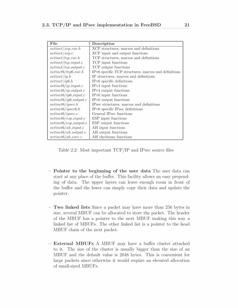
Table 2.2 shows a list of the most important source files referring to IP,XCP, and IPsec with a brief descriptions of them.
2.3.1 Memory Buffers
One of the most important concepts of the FreeBSD stack are the Mem-ory Buffers or MBUFs. These buffers are an essential piece in the entireTCP/IP implementation. The interoperability between the several pro-tocol layers requires an easy manipulation of data made by the functionsthat compose those layers. Prepending, appending and removing data areconstant needs when either a packet is being encapsulated from the upperlayers to the lower layers or headers are removed as the packet crosses upthe protocol stack. The MBUFs were made to support those tasks in avery efficient way. The most important features of MBUFs are as follows:
– Fixed size The size of the MBUF is always equal. The value isdefined in the kernel source and the default size is 256 bytes. Part ofthe size comprises the MBUF header and the remaining the user data.The actual size of each section depends on the type of the MBUF. Amore detailed description of the MBUF header and the various typeswill be made ahead.
– Allows zero length records MBUF size can be null which may berequired by some protocols like UDP.
2.3. TCP/IP and IPsec implementation in FreeBSD 21
File Description
netinet/xcp var.h XCP structures, macros and definitionsnetinet/xcp.c XCP input and output functionsnetinet/tcp var.h TCP structures, macros and definitionsnetinet/tcp input.c TCP input functionsnetinet/tcp output.c TCP output functionsnetinet6/tcp6 var.h IPv6 specific TCP structures, macros and definitionsnetinet/ip.h IP structures, macros and definitionsnetinet/ip6.h IPv6 specific definitionsnetinet6/ip input.c IPv4 input functionsnetinet6/ip output.c IPv4 output functionsnetinet6/ip6 input.c IPv6 input functionsnetinet6/ip6 output.c IPv6 output functionsnetinet6/ipsec.h IPsec structures, macros and definitionsnetinet6/ipsec6.h IPv6 specific IPsec definitionsnetinet6/ipsec.c General IPsec functionsnetinet6/esp input.c ESP input functionsnetinet6/esp output.c ESP output functionsnetinet6/ah input.c AH input functionsnetinet6/ah output.c AH output functionsnetinet6/ah core.c AH checksum functions
Table 2.2: Most important TCP/IP and IPsec source files
– Pointer to the beginning of the user data The user data canstart at any place of the buffer. This facility allows an easy prepend-ing of data. The upper layers can leave enough room in front ofthe buffer and the lower can simply copy their data and update thepointer.
– Two linked lists Since a packet may have more than 256 bytes insize, several MBUF can be allocated to store the packet. The headerof the MBUF has a pointer to the next MBUF making this way alinked list of MBUFs. The other linked list is a pointer to the headMBUF chain of the next packet.
– External MBUFs A MBUF may have a buffer cluster attachedto it. The size of the cluster is usually bigger than the size of anMBUF and the default value is 2048 bytes. This is convenient forlarge packets since otherwise it would require an elevated allocationof small-sized MBUFs.
22 Chapter 2. Technical Background
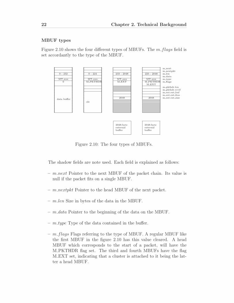
MBUF types
Figure 2.10 shows the four different types of MBUFs. The m flags field isset accordantly to the type of the MBUF.
m nextm nextpkt
0 - 232 0 - 224 233 - 2048 225 - 2048 m lenm data
MT xxx MT xxx MT xxx MT xxx m type0 M PKTHDR M EXT M PKTHDR
M EXTm flags
data buffer
m pkthdr.lenm pkthdr.rcvif
ole
m ext.ext bufm ext.ext free
2048 2048 m ext.ext size
2048-byte 2048-byteexternalbuffer
externalbuffer
Figure 2.10: The four types of MBUFs.
The shadow fields are note used. Each field is explained as follows:
– m next Pointer to the next MBUF of the packet chain. Its value isnull if the packet fits on a single MBUF.
– m nextpkt Pointer to the head MBUF of the next packet.
– m len Size in bytes of the data in the MBUF.
– m data Pointer to the beginning of the data on the MBUF.
– m type Type of the data contained in the buffer.
– m flags Flags referring to the type of MBUF. A regular MBUF likethe first MBUF in the figure 2.10 has this value cleared. A headMBUF which corresponds to the start of a packet, will have theM PKTHDR flag set. The third and fourth MBUFs have the flagM EXT set, indicating that a cluster is attached to it being the lat-ter a head MBUF.
2.3. TCP/IP and IPsec implementation in FreeBSD 23
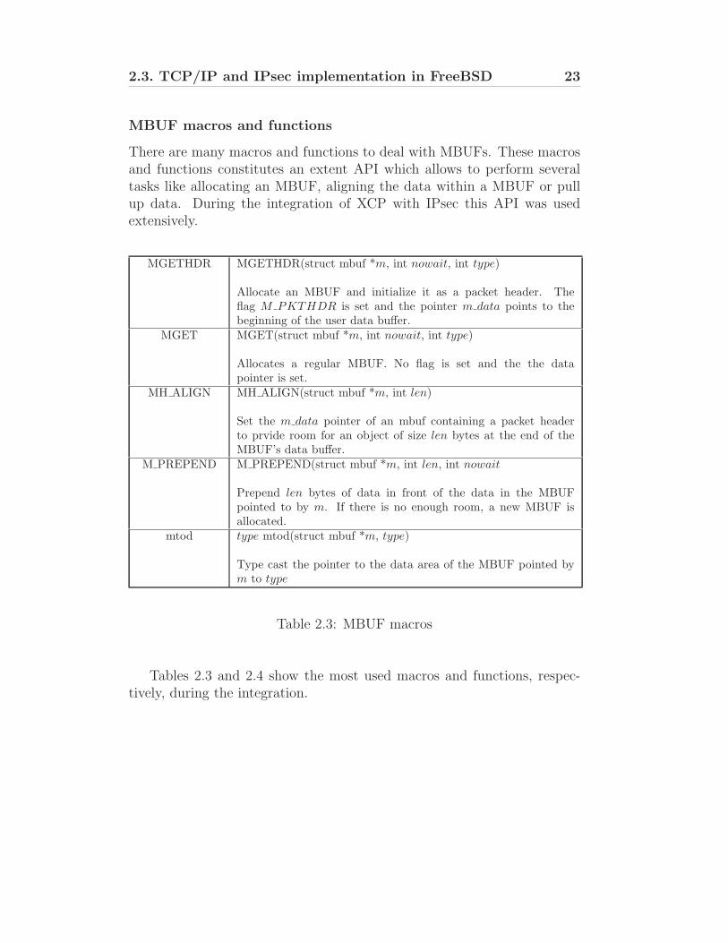
MBUF macros and functions
There are many macros and functions to deal with MBUFs. These macrosand functions constitutes an extent API which allows to perform severaltasks like allocating an MBUF, aligning the data within a MBUF or pullup data. During the integration of XCP with IPsec this API was usedextensively.
MGETHDR MGETHDR(struct mbuf *m, int nowait, int type)
Allocate an MBUF and initialize it as a packet header. Theflag M PKTHDR is set and the pointer m data points to thebeginning of the user data buffer.
MGET MGET(struct mbuf *m, int nowait, int type)
Allocates a regular MBUF. No flag is set and the the datapointer is set.
MH ALIGN MH ALIGN(struct mbuf *m, int len)
Set the m data pointer of an mbuf containing a packet headerto prvide room for an object of size len bytes at the end of theMBUF’s data buffer.
M PREPEND M PREPEND(struct mbuf *m, int len, int nowait
Prepend len bytes of data in front of the data in the MBUFpointed to by m. If there is no enough room, a new MBUF isallocated.
mtod type mtod(struct mbuf *m, type)
Type cast the pointer to the data area of the MBUF pointed bym to type
Table 2.3: MBUF macros
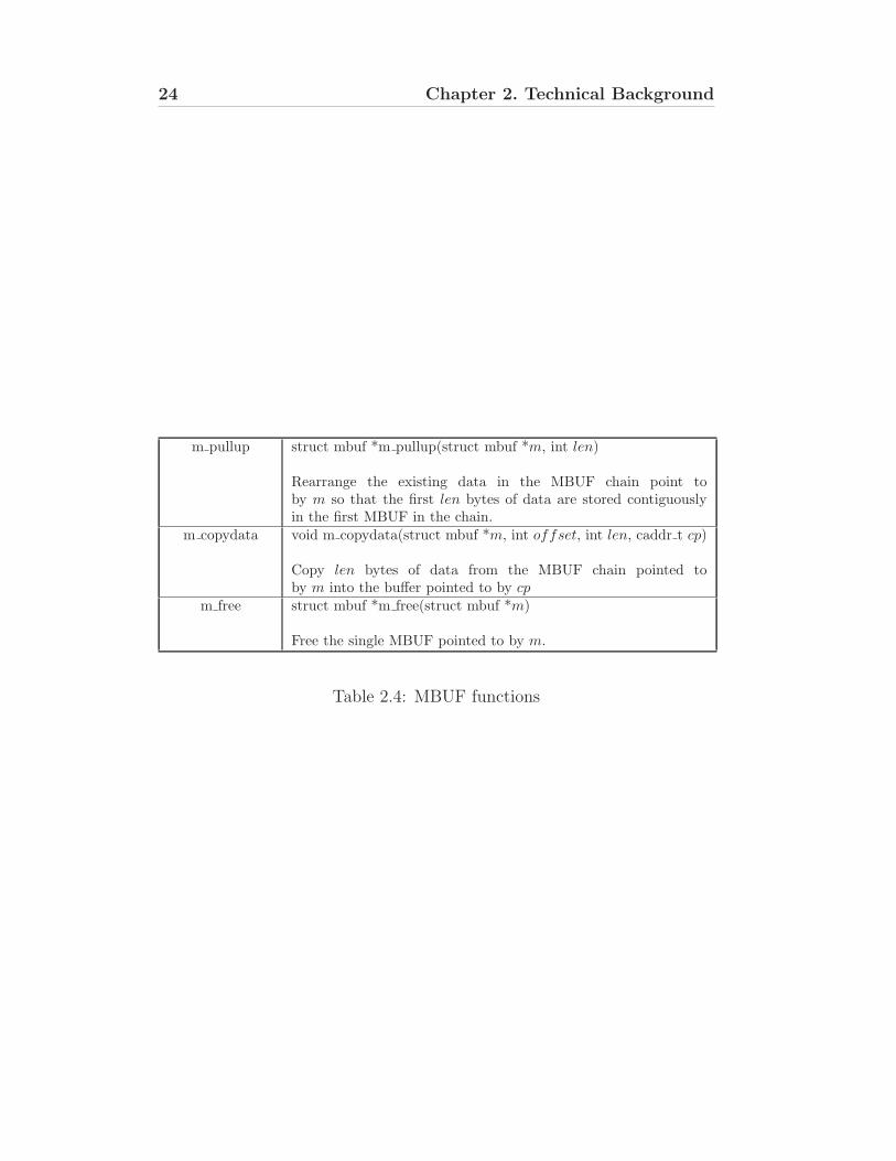
Tables 2.3 and 2.4 show the most used macros and functions, respec-tively, during the integration.
24 Chapter 2. Technical Background
m pullup struct mbuf *m pullup(struct mbuf *m, int len)
Rearrange the existing data in the MBUF chain point toby m so that the first len bytes of data are stored contiguouslyin the first MBUF in the chain.
m copydata void m copydata(struct mbuf *m, int offset, int len, caddr t cp)
Copy len bytes of data from the MBUF chain pointed toby m into the buffer pointed to by cp
m free struct mbuf *m free(struct mbuf *m)
Free the single MBUF pointed to by m.
Table 2.4: MBUF functions
Chapter 3
Integrating XCP with IPsec(IPv4)
XCP integration with IPsec is a necessary step in the protocol’s standariza-tion.
The integration of XCP with IPsec brings advantages to each other.By taking into account network flows based on the IPsec security poli-cies, explicit congestion control protocols gain a better perspective on howfeedback must be distributed amongst participating end-hosts. Conversely,securing the congestion header avoids vulnerabilities in the feedback sys-tem estabilished by protocols like XCP, such as man-in-the-middle attacksmanipulating data used by routers to adjust system performance, or cor-rupting feedback used to adjust an end-host’s send rate.
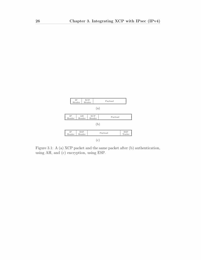
The current implementation of XCP does not yet support IPsec connec-tions for XCP flows. IPsec transforms are defined to be applied immediatelyafter the IP Header. This either does not allow routers along the path tomodify the congestion header due to packet authentication in AH mode,or hides the congestion header from the router altogether if encryption isused in ESP mode. Figure 3.1 shows the current scenario.
To solve this issue, IPsec and TCP/IP implementation must be modifiedin order to be XPC aware and properly insert the congestion header beforeboth the authentication header and encryption header.
25
26 Chapter 3. Integrating XCP with IPsec (IPv4)
IP XCPHeader Header
Payload
(a)
IP AH XCPHeader Header Header
Payload
(b)
IP ESP ESPHeader Header
PayloadTrailer
(c)
Figure 3.1: A (a) XCP packet and the same packet after (b) authentication,using AH, and (c) encryption, using ESP.
3.1. Current scenario 27
3.1 Current scenario
In this section is made a description of the current packet travel from thetransport layer to network layer using IPsec and XCP in IPv4 connections.Also in this section, are identified the restrictions of using IPsec and XCPin IPv4 connections and is shown the implemented solution.
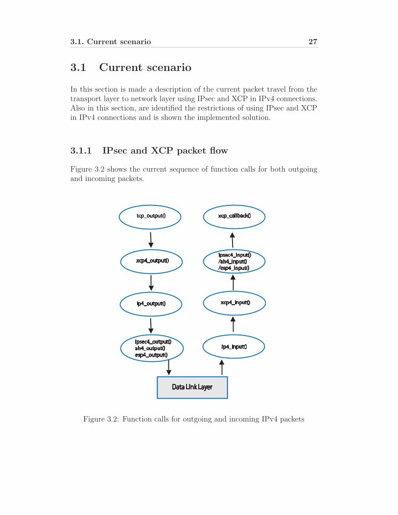
3.1.1 IPsec and XCP packet flow
Figure 3.2 shows the current sequence of function calls for both outgoingand incoming packets.
Data Link Layer
tcp_output()
xcp4_output()
ip4_output()
ipsec4_output()
ah4_output()
esp4_output()
xcp_callback()
ipsec4_input()
/ah4_input()
/esp4_input()
xcp4_input()
ip4_input()
Figure 3.2: Function calls for outgoing and incoming IPv4 packets
28 Chapter 3. Integrating XCP with IPsec (IPv4)
Outgoing packets
1. When a user request of a TCP/XCP socket is made, the tcp output().Among other processings, this function is responsible for data seg-mentation and it size based on the path MTU. Note that for regularTCP sockets, the functions skips the call of XCP output and goesdirectly to IP output.
2. The xcp4 output function is responsible for creating and prepend theXCP header and initialize its values, including the remote feedback,if avaiable.
3. After being called by the XCP output, the ip4 output() function fillsthe IPv4 Header and checks for any security policy based on thedestination address. If a policy should be enforced, the function callsthe IPsec routines.
4. ipsec4 output checks the policies and calls the appropriate securityprotocol, ESP and/or AH. The output function of each protocol willperform transformations upon the packet. At the end, the packetreturns to the ip output which will deliver it to the data link layer.
Incoming packets
1. The data link layer calls the IP input function. This function will dointegrity checks to the incoming packet and afterwards will read fromthe Next Protocol field the IPv4 header and call the appropriate inputfunction. Note that all input functions will return the IP function.The former must provide the next protocol value in order to the lattercall the next input function.
2. The IPsec input functions will process the packet by verifying itsauthenticity and decrypt the payload.
3. The XCP function will remove and store the XCP header for laterprocessing.
4. Finally the TCP input function will assemble the data and call againXCP to process the packet and determinate the proper throughput.
3.1.2 Current limitations and proposed solution
Because the IPsec output functions are called after the XCP processing,the XCP header will be included in the payload of the IP packet, which is
3.1. Current scenario 29
either authenticated or encrypted, not allowing the routers to change theheader. To overcome this limitation the following solution is proposed:
– At the IPsec output functions level, treat the XCP header as an IPv4Header option. Doing so, the XCP header will appear immediatelyafter the IPv4 header and it would not be subject to encryption.
– Add support for the authentication of the new pseudo IPv4 headeroption. Since AH stills authenticates parts of the IPv4 header, theextra fields of XCP should be also authenticated.
– For tunnel mode, modifications to the TCP routine is necessary be-cause of the duplication of the XCP header. As recommended bythe XCP draft, the XCP header should be present in both inner andouter packets.
30 Chapter 3. Integrating XCP with IPsec (IPv4)
3.2 IPsec routines
3.2.1 Separating the congestion header from the IPsecpayload
IPsec performs transformations after separating the outgoing packet in two:the IP header and the respective payload. Although the IP header remainsunchanged, immutable fields may be authenticated and therefore networknodes along the path may not alter some header parameters. Since thepacket payload may be completely authenticated or encrypted, the conges-tion header must be extracted from the payload before the chosen IPsectransform is applied.
Modifying this behaviour requires changes to ipsec4 splithdr(), the func-tion belonging to ipsec.c responsible for separating the IPv4 header fromthe payload. This function is used before applying IPsec transforms and,when called:
1. Receives a pointer, ptr, to a complete IP packet through the function’sargument and copies the pointer’s value to an auxiliary pointer, aux.
2. Increments aux by the IP header length.
3. Checks for IP options and increments aux by the appropriate length.
4. If the packet header, located between ptr and aux, is not stored inthe same mbuf , the packet is realigned to allow header allocation toan individual mbuf . This is a performance optimisation.
5. Return aux, which now points to payload.
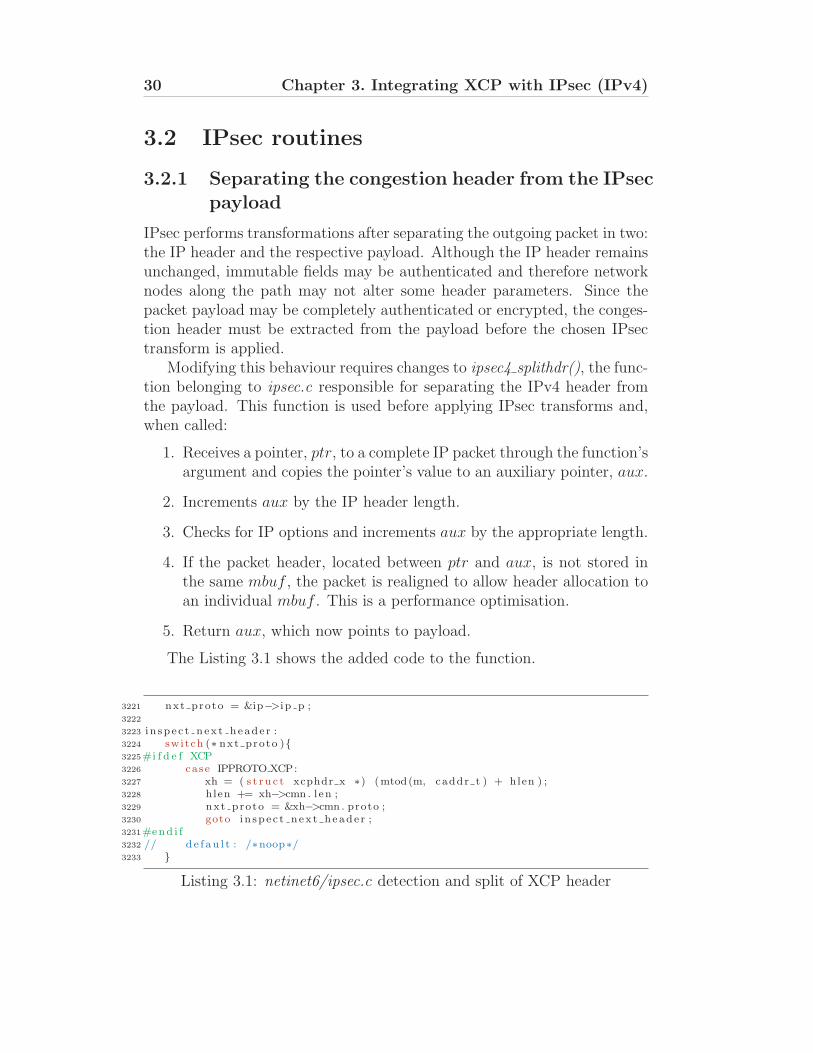
The Listing 3.1 shows the added code to the function.
3221 nxt proto = &ip−>i p p ;3222
3223 i n sp e c t n ex t heade r :3224 switch (∗ nxt proto ){3225#i f d e f XCP3226 case IPPROTO XCP:3227 xh = ( s t r u c t xcphdr x ∗) (mtod(m, caddr t ) + hlen ) ;3228 hlen += xh−>cmn . l en ;3229 nxt proto = &xh−>cmn . proto ;3230 goto i n sp e c t n ex t heade r ;3231#end i f3232 // d e f au l t : /∗noop∗/3233 }
Listing 3.1: netinet6/ipsec.c detection and split of XCP header
3.2. IPsec routines 31
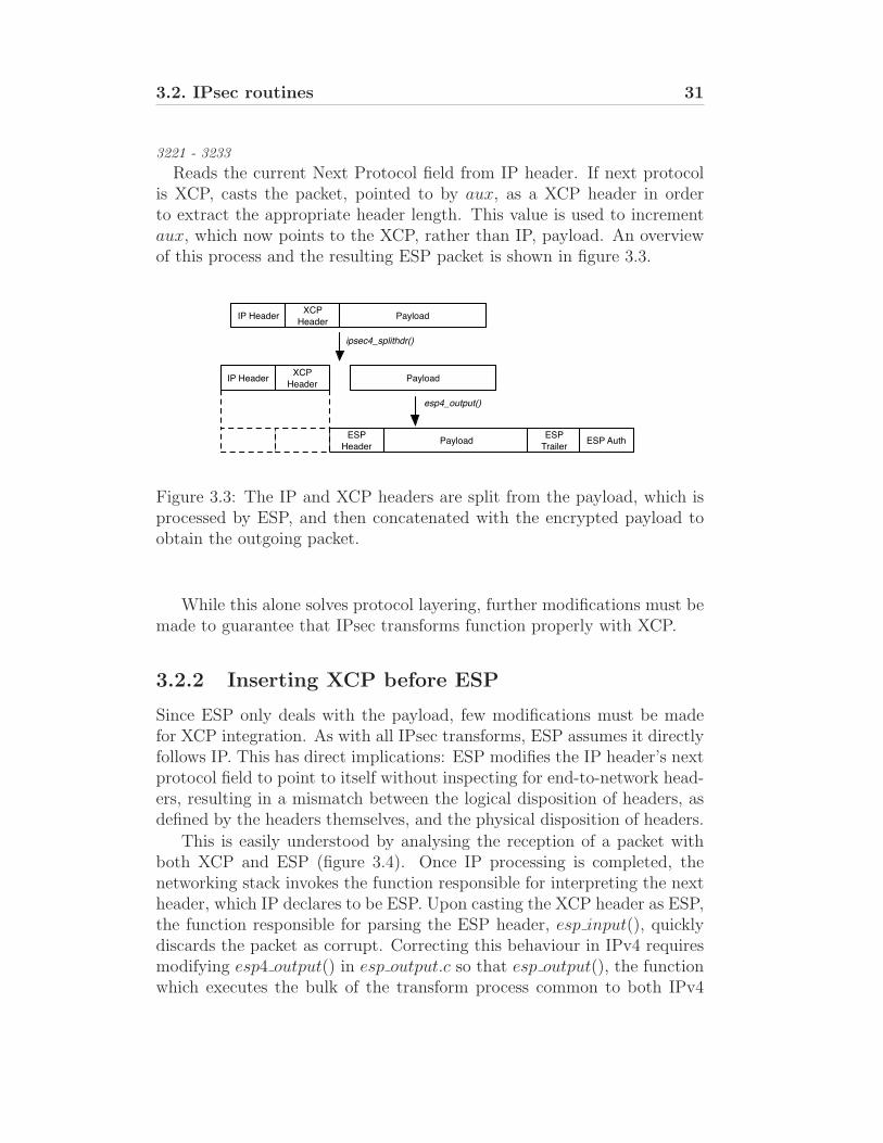
3221 - 3233
Reads the current Next Protocol field from IP header. If next protocolis XCP, casts the packet, pointed to by aux, as a XCP header in orderto extract the appropriate header length. This value is used to incrementaux, which now points to the XCP, rather than IP, payload. An overviewof this process and the resulting ESP packet is shown in figure 3.3.
ipsec4_splithdr()
esp4_output()
IP HeaderXCP
HeaderPayload
IP HeaderXCP
HeaderPayload
ESP
HeaderPayload
ESP
TrailerESP Auth
Figure 3.3: The IP and XCP headers are split from the payload, which isprocessed by ESP, and then concatenated with the encrypted payload toobtain the outgoing packet.
While this alone solves protocol layering, further modifications must bemade to guarantee that IPsec transforms function properly with XCP.
3.2.2 Inserting XCP before ESP
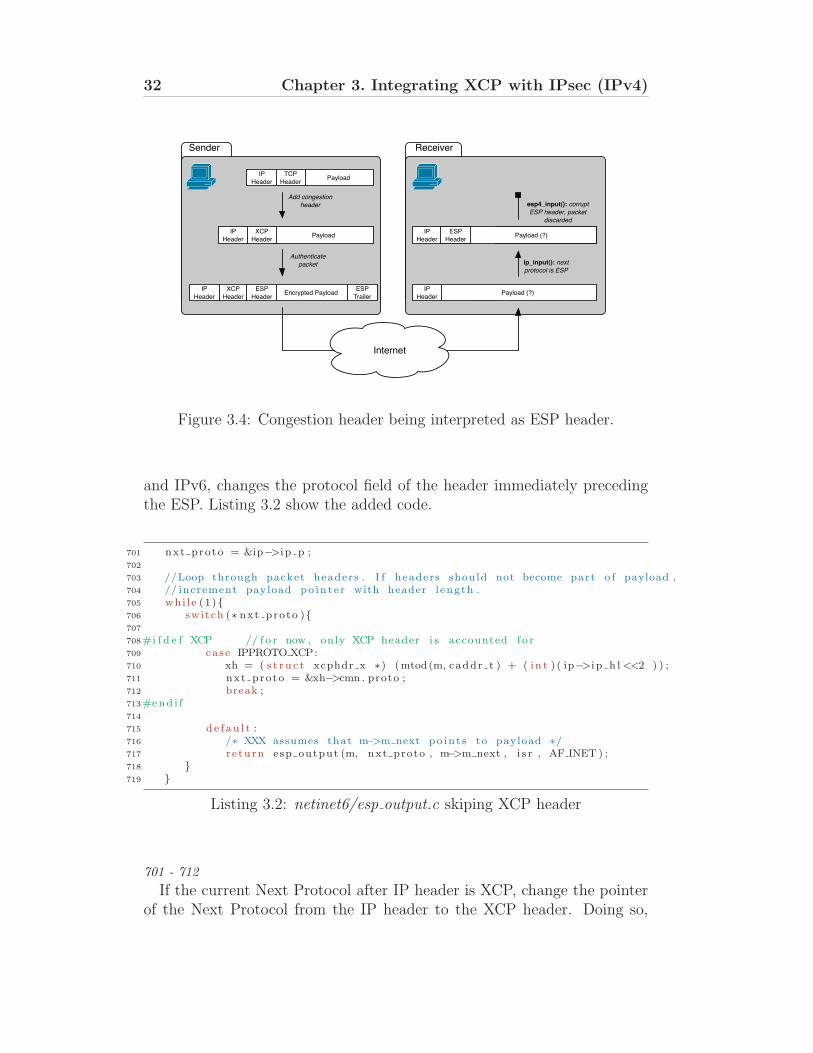
Since ESP only deals with the payload, few modifications must be madefor XCP integration. As with all IPsec transforms, ESP assumes it directlyfollows IP. This has direct implications: ESP modifies the IP header’s nextprotocol field to point to itself without inspecting for end-to-network head-ers, resulting in a mismatch between the logical disposition of headers, asdefined by the headers themselves, and the physical disposition of headers.
This is easily understood by analysing the reception of a packet withboth XCP and ESP (figure 3.4). Once IP processing is completed, thenetworking stack invokes the function responsible for interpreting the nextheader, which IP declares to be ESP. Upon casting the XCP header as ESP,the function responsible for parsing the ESP header, esp input(), quicklydiscards the packet as corrupt. Correcting this behaviour in IPv4 requiresmodifying esp4 output() in esp output.c so that esp output(), the functionwhich executes the bulk of the transform process common to both IPv4
32 Chapter 3. Integrating XCP with IPsec (IPv4)
Payload
Payload
XCP
HeaderEncrypted Payload
Add congestion
header
Authenticate
packet
TCP
Header
Sender
IP
HeaderPayload (?)
AH
HeaderPayload (?)
ip_input(): next
protocol is ESP
esp4_input(): corrupt
ESP header, packet
discarded
IP
HeaderPayload (?)
Internet
Receiver
XCP
Header
IP
Header
TCP
Header
IP
Header
ESP
Header
IP
Header
IP
Header
ESP
Trailer
ESP
Header
Figure 3.4: Congestion header being interpreted as ESP header.
and IPv6, changes the protocol field of the header immediately precedingthe ESP. Listing 3.2 show the added code.
701 nxt proto = &ip−>i p p ;702
703 //Loop through packet headers . I f headers should not become part o f payload ,704 // increment payload po in t e r with header l ength .705 whi le (1){706 switch (∗ nxt proto ){707
708#i f d e f XCP // f o r now , only XCP header i s accounted f o r709 case IPPROTO XCP:710 xh = ( s t r u c t xcphdr x ∗) (mtod(m, caddr t ) + ( i n t ) ( ip−>i p h l <<2 ) ) ;711 nxt proto = &xh−>cmn . proto ;712 break ;713#end i f714
715 de f au l t :716 /∗ XXX assumes that m−>m next po in t s to payload ∗/717 r e turn esp output (m, nxt proto , m−>m next , i s r , AF INET ) ;718 }719 }
Listing 3.2: netinet6/esp output.c skiping XCP header
701 - 712
If the current Next Protocol after IP header is XCP, change the pointerof the Next Protocol from the IP header to the XCP header. Doing so,
3.2. IPsec routines 33
allows the ESP to write its protocol value to the XCP header instead ofthe IP header.
715 - 718
Calls the esp output() with the correct pointer to the Next Protocol.
3.2.3 Inserting XCP before AH
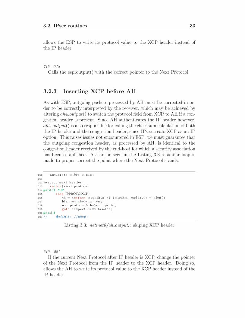
As with ESP, outgoing packets processed by AH must be corrected in or-der to be correctly interpreted by the receiver, which may be achieved byaltering ah4 output() to switch the protocol field from XCP to AH if a con-gestion header is present. Since AH authenticates the IP header however,ah4 output() is also responsible for calling the checksum calculation of boththe IP header and the congestion header, since IPsec treats XCP as an IPoption. This raises issues not encountered in ESP: we must guarantee thatthe outgoing congestion header, as processed by AH, is identical to thecongestion header received by the end-host for which a security associationhas been established. As can be seen in the Listing 3.3 a similar loop ismade to proper correct the point where the Next Protocol stands.
210 nxt proto = &ip−>i p p ;211
212 i n sp e c t n ex t heade r :213 switch (∗ nxt proto ){214#i f d e f XCP215 case IPPROTO XCP:216 xh = ( s t r u c t xcphdr x ∗) (mtod(m, caddr t ) + hlen ) ;217 hlen += xh−>cmn . l en ;218 nxt proto = &xh−>cmn . proto ;219 goto i n sp e c t n ex t heade r ;220#end i f221 // d e f au l t : //noop ;
Listing 3.3: netinet6/ah output.c skiping XCP header
210 - 221
If the current Next Protocol after IP header is XCP, change the pointerof the Next Protocol from the IP header to the XCP header. Doing so,allows the AH to write its protocol value to the XCP header instead of theIP header.
34 Chapter 3. Integrating XCP with IPsec (IPv4)
Authenticating XCP
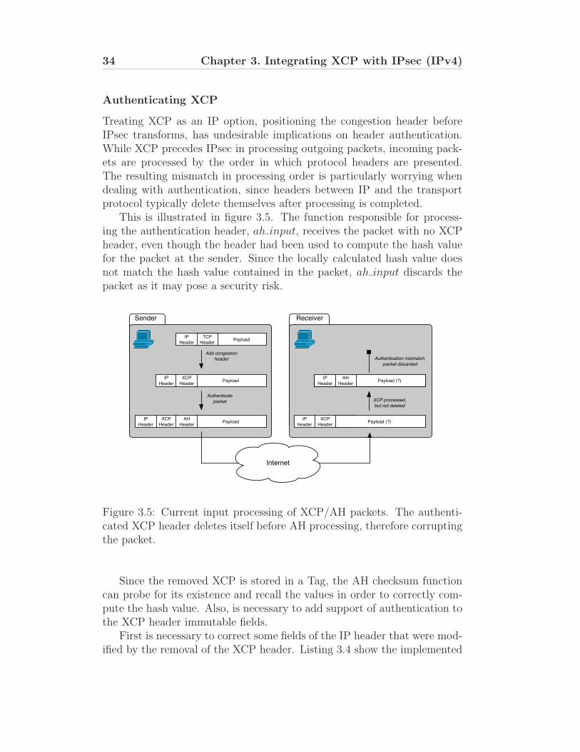
Treating XCP as an IP option, positioning the congestion header beforeIPsec transforms, has undesirable implications on header authentication.While XCP precedes IPsec in processing outgoing packets, incoming pack-ets are processed by the order in which protocol headers are presented.The resulting mismatch in processing order is particularly worrying whendealing with authentication, since headers between IP and the transportprotocol typically delete themselves after processing is completed.
This is illustrated in figure 3.5. The function responsible for process-ing the authentication header, ah input, receives the packet with no XCPheader, even though the header had been used to compute the hash valuefor the packet at the sender. Since the locally calculated hash value doesnot match the hash value contained in the packet, ah input discards thepacket as it may pose a security risk.
Payload
IP
HeaderPayload
XCP
Header
IP
HeaderPayload
AH
Header
IP
HeaderPayload (?)
AH
HeaderPayload (?)
Add congestion
header
Authenticate
packet XCP processed,
but not deleted
Authentication mismatch,
packet discarded
XCP
HeaderPayload (?)
Internet
TCP
Header
Sender Receiver
TCP
Header
IP
Header
XCP
Header
AH
Header
XCP
Header
IP
Header
IP
Header
AH
Header
Figure 3.5: Current input processing of XCP/AH packets. The authenti-cated XCP header deletes itself before AH processing, therefore corruptingthe packet.
Since the removed XCP is stored in a Tag, the AH checksum functioncan probe for its existence and recall the values in order to correctly com-pute the hash value. Also, is necessary to add support of authentication tothe XCP header immutable fields.
First is necessary to correct some fields of the IP header that were mod-ified by the removal of the XCP header. Listing 3.4 show the implemented
3.2. IPsec routines 35
code.
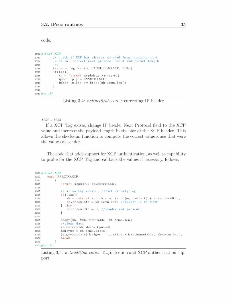
1232#i f d e f XCP1233 /∗ check i f XCP has a l r eady de l e t ed from incoming mbuf1234 ∗ i f so , c o r r e c t next p ro to co l f i e l d and packet l ength1235 ∗/1236 tag = m tag f ind (m, PACKET TAG XCP, NULL) ;1237 i f ( tag ){1238 xh = ( s t r u c t xcphdr x ∗ ) ( tag +1);1239 iphdr . ip p = IPPROTO XCP;1240 iphdr . i p l e n += htons (xh−>cmn . l en ) ;1241 }1242
1243#end i f
Listing 3.4: netinet6/ah core.c correcting IP header
1232 - 1243
If a XCP Tag exists, change IP header Next Protocol field to the XCPvalue and increase the payload length in the size of the XCP header. Thisallows the checksum function to compute the correct value since that werethe values at sender.
The code that adds support for XCP authentication, as well as capabilityto probe for the XCP Tag and callback the values if necessary, follows:
1352#i f d e f XCP1353 case IPPROTO XCP:1354 {1355 s t r u c t xcphdr x xh immutable ;1356
1357 // i f no tag ex i s t s , packet i s outgoing1358 i f ( ! tag ){1359 xh = ( s t r u c t xcphdr x ∗) (mtod(m, caddr t ) + advancewidth ) ;1360 advancewidth = xh−>cmn . l en ; // header i s in mbuf1361 } e l s e {1362 advancewidth = 0 ; // header not pre sent .1363 }1364
1365 bcopy (xh , &xh immutable , xh−>cmn . l en ) ;1366 // c l e a r data1367 xh immutable . d e l t a tpu t =0;1368 hdrtype = xh−>cmn . proto ;1369 ( algo−>update )(& algos , ( u i n t 8 t ∗)&xh immutable , xh−>cmn . l en ) ;1370 break ;1371 }1372#end i f
Listing 3.5: netinet6/ah core.c Tag detection and XCP authentication sup-port
36 Chapter 3. Integrating XCP with IPsec (IPv4)
1352 - 1363
Defines the advance in bytes for the next loop cycle. If no tag exists, thepacket is outgoing, and the header is present then the advance value is theXCP length.
1365 - 1370
Copies the XCP header to a temporary variable and sets the mutablefield, Delta Throughput, to zero and then calls the hash algorithm func-tion.
3.3. Tunnel Mode 37
3.3 Tunnel Mode
PayloadInner IP
Header
XCP
Header
Outer IP
Header
XCP
Header
PayloadIP
Header
XCP
HeaderPayload
IP
Header
XCP
Header
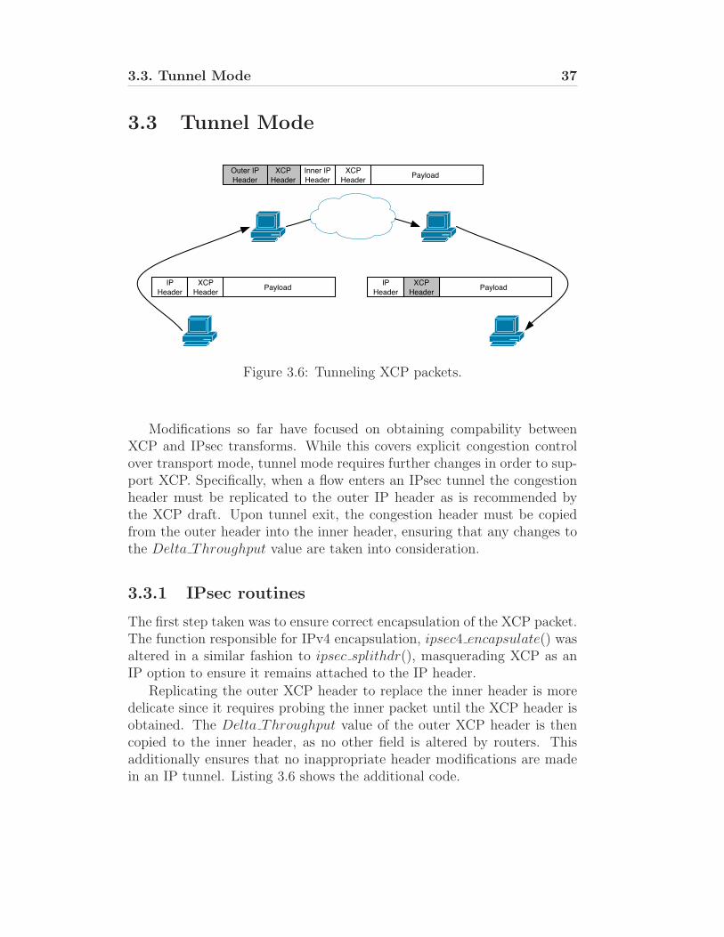
Figure 3.6: Tunneling XCP packets.
Modifications so far have focused on obtaining compability betweenXCP and IPsec transforms. While this covers explicit congestion controlover transport mode, tunnel mode requires further changes in order to sup-port XCP. Specifically, when a flow enters an IPsec tunnel the congestionheader must be replicated to the outer IP header as is recommended bythe XCP draft. Upon tunnel exit, the congestion header must be copiedfrom the outer header into the inner header, ensuring that any changes tothe Delta Throughput value are taken into consideration.
3.3.1 IPsec routines
The first step taken was to ensure correct encapsulation of the XCP packet.The function responsible for IPv4 encapsulation, ipsec4 encapsulate() wasaltered in a similar fashion to ipsec splithdr(), masquerading XCP as anIP option to ensure it remains attached to the IP header.
Replicating the outer XCP header to replace the inner header is moredelicate since it requires probing the inner packet until the XCP header isobtained. The Delta Throughput value of the outer XCP header is thencopied to the inner header, as no other field is altered by routers. Thisadditionally ensures that no inappropriate header modifications are madein an IP tunnel. Listing 3.6 shows the additional code.
38 Chapter 3. Integrating XCP with IPsec (IPv4)
377#i f d e f XCP378 i f ( tag ){379 xh = ( s t r u c t xcphdr x ∗) (mtod(m, caddr t ) + ( i n t ) ( ip−>i p h l <<2 ) ) ;380 xh−>de l t a tpu t = xt−>de l t a tpu t ;381 }382#end i f
Listing 3.6: netinet6/esp input.c Tag detection and XCP authenticationsupport
If a XCP Tag exists, the Delta Throughput value stored in the Tag iscopied to the same field of the inner XCP header.
3.3.2 TCP Output
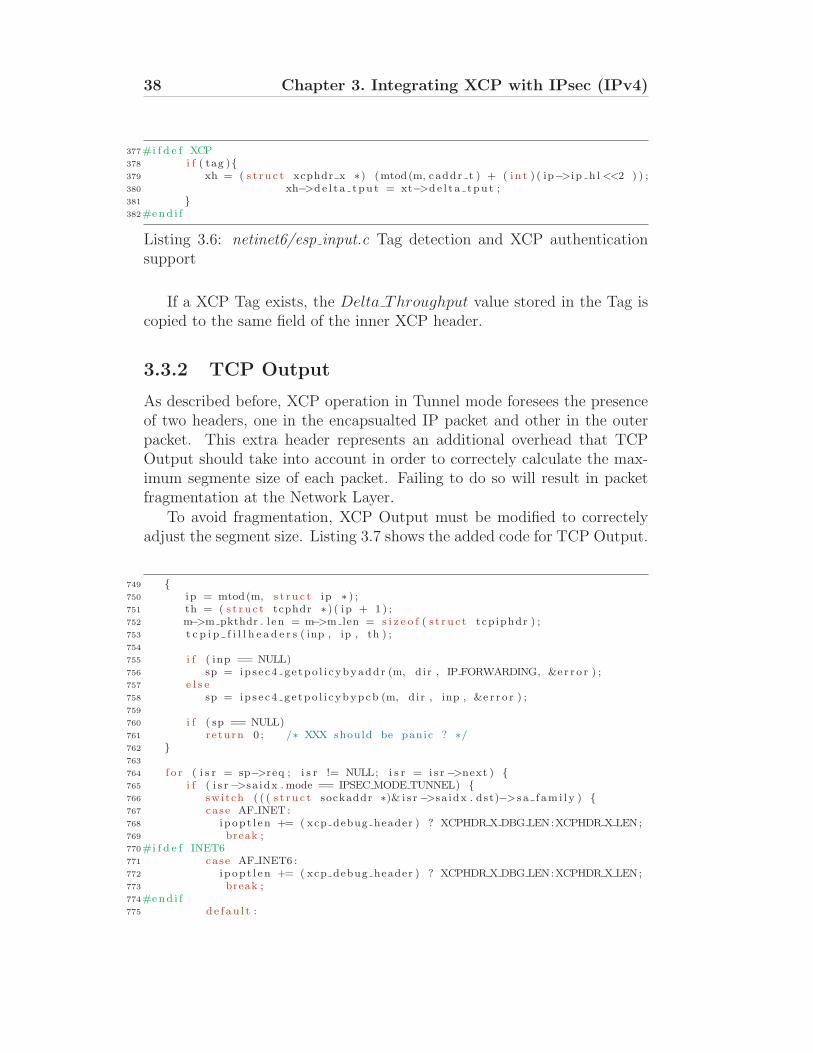
As described before, XCP operation in Tunnel mode foresees the presenceof two headers, one in the encapsualted IP packet and other in the outerpacket. This extra header represents an additional overhead that TCPOutput should take into account in order to correctely calculate the max-imum segmente size of each packet. Failing to do so will result in packetfragmentation at the Network Layer.
To avoid fragmentation, XCP Output must be modified to correctelyadjust the segment size. Listing 3.7 shows the added code for TCP Output.
749 {750 ip = mtod(m, s t r u c t ip ∗ ) ;751 th = ( s t r u c t tcphdr ∗ ) ( ip + 1 ) ;752 m−>m pkthdr . l en = m−>m len = s i z e o f ( s t r u c t tcp iphdr ) ;753 t c p i p f i l l h e a d e r s ( inp , ip , th ) ;754
755 i f ( inp == NULL)756 sp = ip s e c4 g e tpo l i c ybyadd r (m, dir , IP FORWARDING, &e r r o r ) ;757 e l s e758 sp = ip s e c4 ge tpo l i c ybypcb (m, dir , inp , &e r r o r ) ;759
760 i f ( sp == NULL)761 r e turn 0 ; /∗ XXX should be panic ? ∗/762 }763
764 f o r ( i s r = sp−>req ; i s r != NULL; i s r = i s r −>next ) {765 i f ( i s r −>sa idx . mode == IPSEC MODE TUNNEL) {766 switch ( ( ( s t r u c t sockaddr ∗)& i s r −>sa idx . dst)−>s a f am i l y ) {767 case AF INET :768 i p op t l en += ( xcp debug header ) ? XCPHDR X DBG LEN:XCPHDR X LEN;769 break ;770#i f d e f INET6771 case AF INET6 :772 i p op t l en += ( xcp debug header ) ? XCPHDR X DBG LEN:XCPHDR X LEN;773 break ;774#end i f775 de f au l t :
3.3. Tunnel Mode 39
776 i p s e c l o g ( (LOG ERR, ” i p s e c h d r s i z : ”777 ”unknown AF %d in IPsec tunne l SA\n” ,778 ( ( s t r u c t sockaddr ∗)& i s r −>sa idx . dst)−>s a f am i l y ) ) ;779 break ;780 }781 }782 }
Listing 3.7: netinet6/tcp output.c maximum segment size
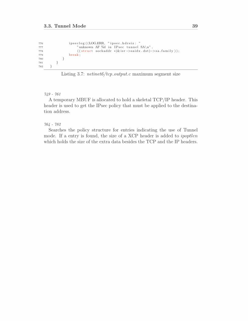
749 - 761
A temporary MBUF is allocated to hold a skeletal TCP/IP header. Thisheader is used to get the IPsec policy that must be applied to the destina-tion address.
764 - 782
Searches the policy structure for entries indicating the use of Tunnelmode. If a entry is found, the size of a XCP header is added to ipoptlenwhich holds the size of the extra data besides the TCP and the IP headers.

Chapter 4
Integrating XCP with IPsec(IPv6)
This chapter presents the implementation of IPsec with XCP for IPv6 net-works. Since IPsec support is mandatory in IPv6 implementations, theawareness of end-to-network protocols becomes an even more importantmatter in order to provide explicit congestion control for the future net-works without compromising security. The outline of the chapter followsthe previous one. First is presented the current scenario for IPv6 flowsusing XCP and IPsec. Afterwards, the current issues are pointed and aproposed solution is shown. Finally in the sections 4.2 through 4.5 theimplementation of the proposed solution is described.
41
42 Chapter 4. Integrating XCP with IPsec (IPv6)
4.1 Current scenario
In this section is made a description of the current packet travel from thetransport layer to network layer using IPsec and XCP in IPv6 connections.Also in this section, are identified the restrictions of using IPsec and XCPand is shown the proposed solution.
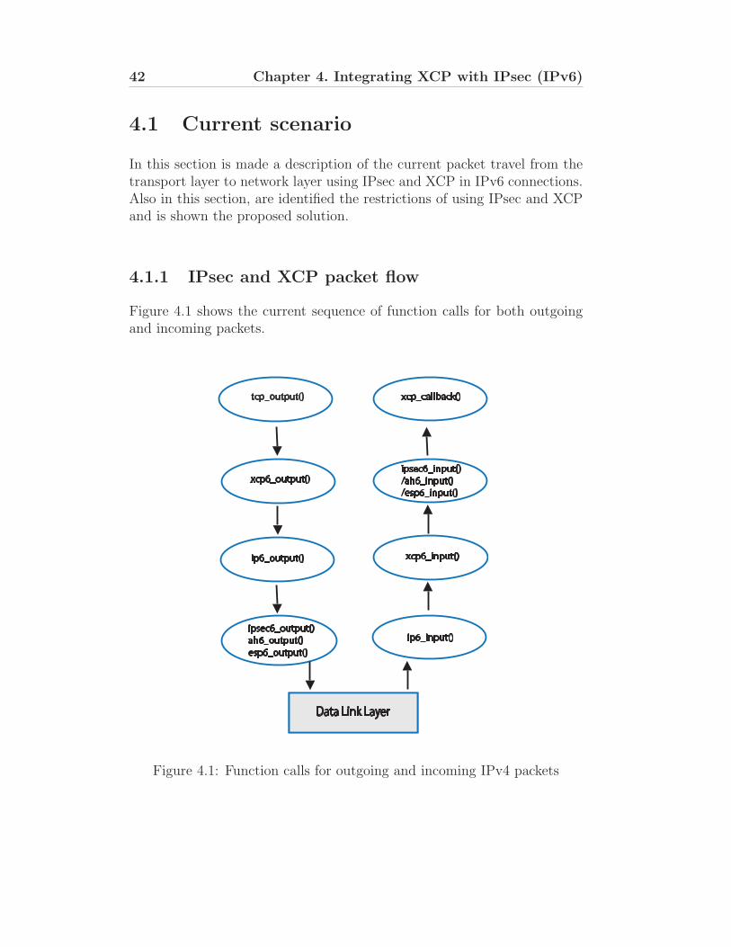
4.1.1 IPsec and XCP packet flow
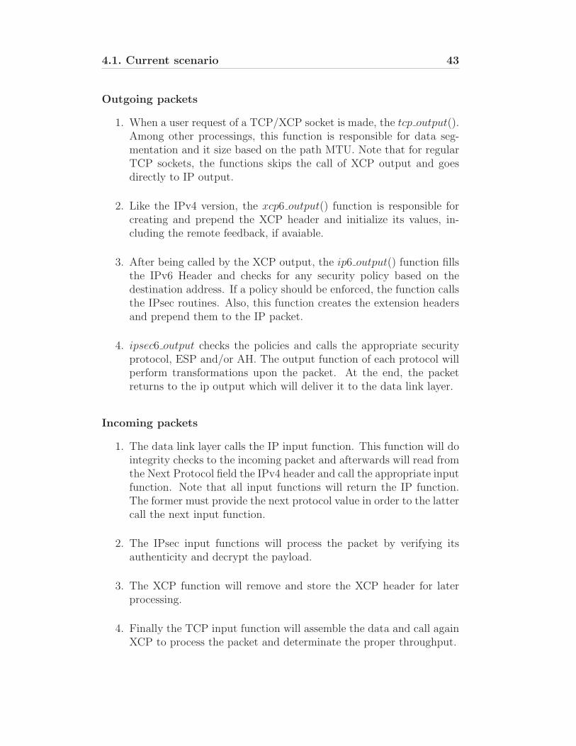
Figure 4.1 shows the current sequence of function calls for both outgoingand incoming packets.
Data Link Layer
tcp_output()
xcp6_output()
ip6_output()
ipsec6_output()
ah6_output()
esp6_output()
xcp_callback()
ipsec6_input()
/ah6_input()
/esp6_input()
xcp6_input()
ip6_input()
Figure 4.1: Function calls for outgoing and incoming IPv4 packets
4.1. Current scenario 43
Outgoing packets
1. When a user request of a TCP/XCP socket is made, the tcp output().Among other processings, this function is responsible for data seg-mentation and it size based on the path MTU. Note that for regularTCP sockets, the functions skips the call of XCP output and goesdirectly to IP output.
2. Like the IPv4 version, the xcp6 output() function is responsible forcreating and prepend the XCP header and initialize its values, in-cluding the remote feedback, if avaiable.
3. After being called by the XCP output, the ip6 output() function fillsthe IPv6 Header and checks for any security policy based on thedestination address. If a policy should be enforced, the function callsthe IPsec routines. Also, this function creates the extension headersand prepend them to the IP packet.
4. ipsec6 output checks the policies and calls the appropriate securityprotocol, ESP and/or AH. The output function of each protocol willperform transformations upon the packet. At the end, the packetreturns to the ip output which will deliver it to the data link layer.
Incoming packets
1. The data link layer calls the IP input function. This function will dointegrity checks to the incoming packet and afterwards will read fromthe Next Protocol field the IPv4 header and call the appropriate inputfunction. Note that all input functions will return the IP function.The former must provide the next protocol value in order to the lattercall the next input function.
2. The IPsec input functions will process the packet by verifying itsauthenticity and decrypt the payload.
3. The XCP function will remove and store the XCP header for laterprocessing.
4. Finally the TCP input function will assemble the data and call againXCP to process the packet and determinate the proper throughput.
44 Chapter 4. Integrating XCP with IPsec (IPv6)
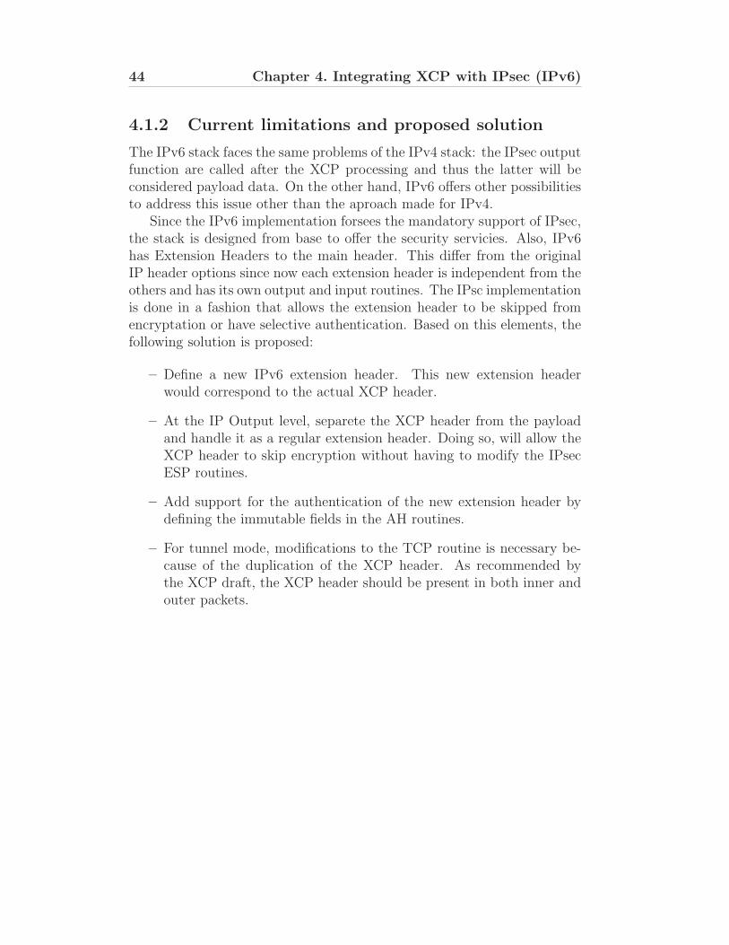
4.1.2 Current limitations and proposed solution
The IPv6 stack faces the same problems of the IPv4 stack: the IPsec outputfunction are called after the XCP processing and thus the latter will beconsidered payload data. On the other hand, IPv6 offers other possibilitiesto address this issue other than the aproach made for IPv4.
Since the IPv6 implementation forsees the mandatory support of IPsec,the stack is designed from base to offer the security servicies. Also, IPv6has Extension Headers to the main header. This differ from the originalIP header options since now each extension header is independent from theothers and has its own output and input routines. The IPsc implementationis done in a fashion that allows the extension header to be skipped fromencryptation or have selective authentication. Based on this elements, thefollowing solution is proposed:
– Define a new IPv6 extension header. This new extension headerwould correspond to the actual XCP header.
– At the IP Output level, separete the XCP header from the payloadand handle it as a regular extension header. Doing so, will allow theXCP header to skip encryption without having to modify the IPsecESP routines.
– Add support for the authentication of the new extension header bydefining the immutable fields in the AH routines.
– For tunnel mode, modifications to the TCP routine is necessary be-cause of the duplication of the XCP header. As recommended bythe XCP draft, the XCP header should be present in both inner andouter packets.
4.2. IP Output routines 45
4.2 IP Output routines
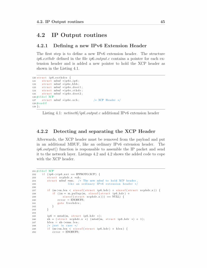
4.2.1 Defining a new IPv6 Extension Header
The first step is to define a new IPv6 extension header. The structureip6 exthdr defined in the file ip6 output.c contains a pointer for each ex-tension header and is added a new pointer to hold the XCP header asshown in the Listing 4.1.
120 s t r u c t i p6 ex thdr s {121 s t r u c t mbuf ∗ i p 6 e i p 6 ;122 s t r u c t mbuf ∗ ip6e hbh ;123 s t r u c t mbuf ∗ i p 6 e d e s t 1 ;124 s t r u c t mbuf ∗ i p 6 e r thd r ;125 s t r u c t mbuf ∗ i p 6 e d e s t 2 ;126#i f d e f XCP127 s t r u c t mbuf ∗ i p6e xch ; /∗ XCP Header ∗/128#end i f129 } ;
Listing 4.1: netinet6/ip6 output.c additional IPv6 extension header
4.2.2 Detecting and separating the XCP Header
Afterwards, the XCP header must be removed from the payload and putin an additional MBUF, like an ordinary IPv6 extension header. Theip6 output() function is responsable to assemble the IP packet and sendit to the network layer. Listings 4.2 and 4.2 shows the added code to copewith the XCP header.
231#i f d e f XCP232 i f ( ip6−>i p6 nxt == IPPROTO XCP) {233 s t r u c t xcphdr x ∗xh ;234 s t r u c t mbuf ∗mx; /∗ The new mbuf to hold XCP header ,235 l i k e an ord inary IPv6 extens i on header ∗/236
237 i f (m−>m len < s i z e o f ( s t r u c t ip6 hdr ) + s i z e o f ( s t r u c t xcphdr x ) ) {238 i f ( (m = m pullup (m, s i z e o f ( s t r u c t ip6 hdr ) +239 s i z e o f ( s t r u c t xcphdr x ) ) ) == NULL) {240 e r r o r = ENOBUFS;241 goto f r e ehd r s ;242 }243 }244
245 ip6 = mtod(m, s t r u c t ip6 hdr ∗ ) ;246 xh = ( s t r u c t xcphdr x ∗) (mtod(m, s t r u c t ip6 hdr ∗) + 1 ) ;247 hlen = xh−>cmn . l en ;248 /∗ j u s t in case ∗/249 i f (m−>m len < s i z e o f ( s t r u c t ip6 hdr ) + hlen ) {250 e r r o r = ENOBUFS;
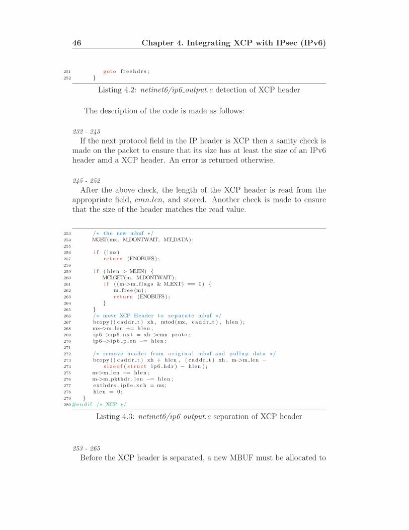
46 Chapter 4. Integrating XCP with IPsec (IPv6)
251 goto f r e ehd r s ;252 }
Listing 4.2: netinet6/ip6 output.c detection of XCP header
The description of the code is made as follows:
232 - 243
If the next protocol field in the IP header is XCP then a sanity check ismade on the packet to ensure that its size has at least the size of an IPv6header amd a XCP header. An error is returned otherwise.
245 - 252
After the above check, the length of the XCP header is read from theappropriate field, cmn.len, and stored. Another check is made to ensurethat the size of the header matches the read value.
253 /∗ the new mbuf ∗/254 MGET(mx, M DONTWAIT, MTDATA) ;255
256 i f ( !mx)257 r e turn (ENOBUFS) ;258
259 i f ( h len > MLEN) {260 MCLGET(m, MDONTWAIT) ;261 i f ( (m−>m f lags & M EXT) == 0) {262 m free (m) ;263 r e turn (ENOBUFS) ;264 }265 }266 /∗ move XCP Header to s epara t e mbuf ∗/267 bcopy ( ( caddr t ) xh , mtod(mx, caddr t ) , h len ) ;268 mx−>m len += hlen ;269 ip6−>i p6 nxt = xh−>cmn . proto ;270 ip6−>i p 6 p l en −= hlen ;271
272 /∗ remove header from o r i g i n a l mbuf and pul lup data ∗/273 bcopy ( ( caddr t ) xh + hlen , ( caddr t ) xh , m−>m len −274 s i z e o f ( s t r u c t ip6 hdr ) − hlen ) ;275 m−>m len −= hlen ;276 m−>m pkthdr . l en −= hlen ;277 exthdrs . ip6e xch = mx;278 hlen = 0 ;279 }280#end i f /∗ XCP ∗/
Listing 4.3: netinet6/ip6 output.c separation of XCP header
253 - 265
Before the XCP header is separated, a new MBUF must be allocated to
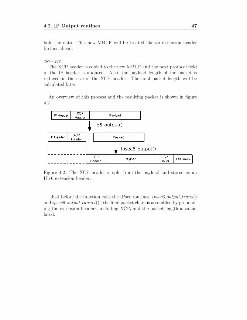
4.2. IP Output routines 47
hold the data. This new MBUF will be treated like an extension headerfurther ahead.
267 - 279
The XCP header is copied to the new MBUF and the next protocol fieldin the IP header is updated. Also, the payload length of the packet isreduced in the size of the XCP header. The final packet length will becalculated later.
An overview of this process and the resulting packet is shown in figure4.2.
Figure 4.2: The XCP header is split from the payload and stored as anIPv6 extension header.
Just before the function calls the IPsec routines, ipsec6 output trans()and ipsec6 output tunnel() , the final packet chain is assembled by prepend-ing the extension headers, including XCP, and the packet length is calcu-lated.
48 Chapter 4. Integrating XCP with IPsec (IPv6)
4.3 IPsec routines
The IPsec routines are called during the IP packet assemble in ip6 output()function. The latter checks if the destinations falls in any SA policies forthe outgoing flows and calls the ipsec6 output trans(). This function doesthe following when is called:
1. Receives a pointer to the head MBUF, a pointer to the MBUF con-taining the extension header prior the IP payload and a pointer tothe next protocol value stored in this last extension header.
2. Checks if all the pointers are valid and if the SA data is present.
3. If the IPsec mode is Tunnel, exits the function and returns to the IPoutput in order to the tunnel routine to be called.
4. Checks the IPsec transformation to be applyed to the packet. If itis ESP, calls the esp6 output() function, else if it is AH, calls theah6 output() function.
5. After the packet is processed by the appropriate protocol, the finallength is set and the function returns to IP output.
Since the ESP output function only encrypts the data starting from thelast extension header, no change is needed on the output function. TheXCP header will be excluded from the process.
4.3.1 AH functions
Concerning AH, the extension headers are used in the overall packet au-thentication by the hash functions, so further modifications to this routinesmust be made to cope with XCP.
In order to support XCP header authentication correctly, ah6 calccksum()the function responsible for calculating the packet checksum, must be mod-ified. Rather than computing the complete congestion header with nodifferentiation between parameters, AH copies the XCP header with nodifferentiation between parameters, AH copies the XCP header and setsthe Delta Throughput mutable field to zero. Since the modified functionis contained in ah core.c, both outgoing and incoming processing will be-have in the same manner therefore ensuring that the hash values will match.Hence Delta Throughput is always set to zero, the parameter can be safelyaltered by the routers along the path.
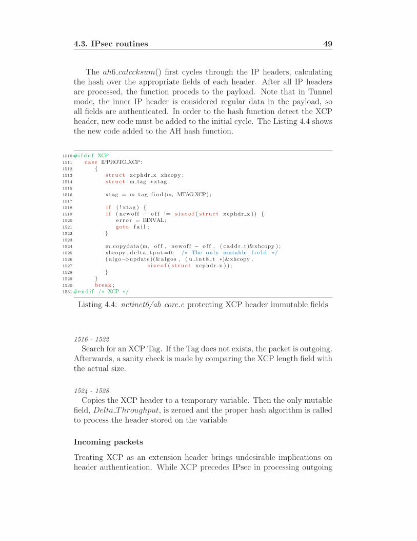
4.3. IPsec routines 49
The ah6 calccksum() first cycles through the IP headers, calculatingthe hash over the appropriate fields of each header. After all IP headersare processed, the function proceds to the payload. Note that in Tunnelmode, the inner IP header is considered regular data in the payload, soall fields are authenticated. In order to the hash function detect the XCPheader, new code must be added to the initial cycle. The Listing 4.4 showsthe new code added to the AH hash function.
1510#i f d e f XCP1511 case IPPROTO XCP:1512 {1513 s t r u c t xcphdr x xhcopy ;1514 s t r u c t m tag ∗xtag ;1515
1516 xtag = m tag f ind (m, MTAGXCP) ;1517
1518 i f ( ! xtag ) {1519 i f ( newof f − o f f != s i z e o f ( s t r u c t xcphdr x ) ) {1520 e r r o r = EINVAL;1521 goto f a i l ;1522 }1523
1524 m copydata (m, o f f , newof f − o f f , ( caddr t )&xhcopy ) ;1525 xhcopy . d e l t a tpu t =0; /∗ The only mutable f i e l d ∗/1526 ( algo−>update )(& algos , ( u i n t 8 t ∗)&xhcopy ,1527 s i z e o f ( s t r u c t xcphdr x ) ) ;1528 }1529 }1530 break ;1531#end i f /∗ XCP ∗/
Listing 4.4: netinet6/ah core.c protecting XCP header immutable fields
1516 - 1522
Search for an XCP Tag. If the Tag does not exists, the packet is outgoing.Afterwards, a sanity check is made by comparing the XCP length field withthe actual size.
1524 - 1528
Copies the XCP header to a temporary variable. Then the only mutablefield, Delta Throughput, is zeroed and the proper hash algorithm is calledto process the header stored on the variable.
Incoming packets
Treating XCP as an extension header brings undesirable implications onheader authentication. While XCP precedes IPsec in processing outgoing
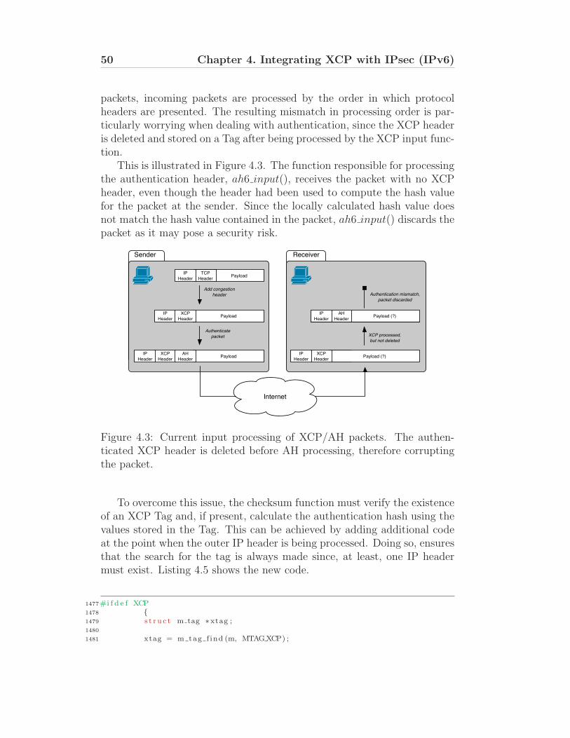
50 Chapter 4. Integrating XCP with IPsec (IPv6)
packets, incoming packets are processed by the order in which protocolheaders are presented. The resulting mismatch in processing order is par-ticularly worrying when dealing with authentication, since the XCP headeris deleted and stored on a Tag after being processed by the XCP input func-tion.
This is illustrated in Figure 4.3. The function responsible for processingthe authentication header, ah6 input(), receives the packet with no XCPheader, even though the header had been used to compute the hash valuefor the packet at the sender. Since the locally calculated hash value doesnot match the hash value contained in the packet, ah6 input() discards thepacket as it may pose a security risk.
Payload
IP
HeaderPayload
XCP
Header
IP
HeaderPayload
AH
Header
IP
HeaderPayload (?)
AH
HeaderPayload (?)
Add congestion
header
Authenticate
packet XCP processed,
but not deleted
Authentication mismatch,
packet discarded
XCP
HeaderPayload (?)
Internet
TCP
Header
Sender Receiver
TCP
Header
IP
Header
XCP
Header
AH
Header
XCP
Header
IP
Header
IP
Header
AH
Header
Figure 4.3: Current input processing of XCP/AH packets. The authen-ticated XCP header is deleted before AH processing, therefore corruptingthe packet.
To overcome this issue, the checksum function must verify the existenceof an XCP Tag and, if present, calculate the authentication hash using thevalues stored in the Tag. This can be achieved by adding additional codeat the point when the outer IP header is being processed. Doing so, ensuresthat the search for the tag is always made since, at least, one IP headermust exist. Listing 4.5 shows the new code.
1477#i f d e f XCP1478 {1479 s t r u c t m tag ∗xtag ;1480
1481 xtag = m tag f ind (m, MTAGXCP) ;
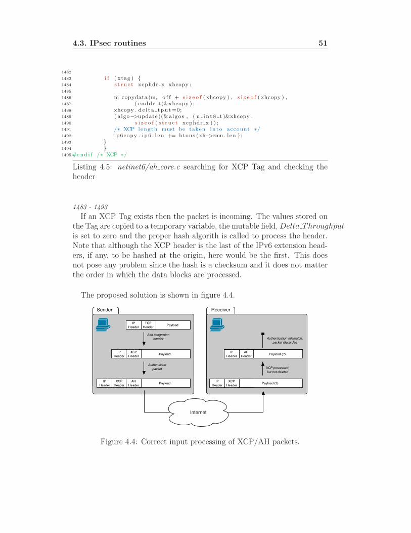
4.3. IPsec routines 51
1482
1483 i f ( xtag ) {1484 s t r u c t xcphdr x xhcopy ;1485
1486 m copydata (m, o f f + s i z e o f ( xhcopy ) , s i z e o f ( xhcopy ) ,1487 ( caddr t )&xhcopy ) ;1488 xhcopy . d e l t a tpu t =0;1489 ( algo−>update )(& algos , ( u i n t 8 t )&xhcopy ,1490 s i z e o f ( s t r u c t xcphdr x ) ) ;1491 /∗ XCP length must be taken in to account ∗/1492 ip6copy . i p 6 l e n += htons (xh−>cmn . l en ) ;1493 }1494 }1495#end i f /∗ XCP ∗/
Listing 4.5: netinet6/ah core.c searching for XCP Tag and checking theheader
1483 - 1493
If an XCP Tag exists then the packet is incoming. The values stored onthe Tag are copied to a temporary variable, the mutable field, Delta Throughputis set to zero and the proper hash algorith is called to process the header.Note that although the XCP header is the last of the IPv6 extension head-ers, if any, to be hashed at the origin, here would be the first. This doesnot pose any problem since the hash is a checksum and it does not matterthe order in which the data blocks are processed.
The proposed solution is shown in figure 4.4.
Payload
IP
HeaderPayload
XCP
Header
IP
HeaderPayload
AH
Header
IP
HeaderPayload (?)
AH
HeaderPayload (?)
Add congestion
header
Authenticate
packet XCP processed,
but not deleted
Authentication mismatch,
packet discarded
XCP
HeaderPayload (?)
Internet
TCP
Header
Sender Receiver
TCP
Header
IP
Header
XCP
Header
AH
Header
XCP
Header
IP
Header
IP
Header
AH
Header
Figure 4.4: Correct input processing of XCP/AH packets.
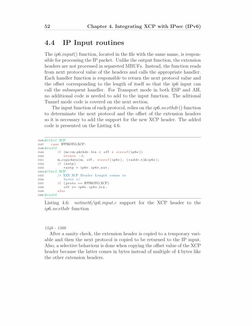
52 Chapter 4. Integrating XCP with IPsec (IPv6)
4.4 IP Input routines
The ip6 input() function, located in the file with the same name, is respon-sible for processing the IP packet. Unlike the output function, the extensionheaders are not processed in separeted MBUFs. Instead, the function readsfrom next protocol value of the headers and calls the appropriate handler.Each handler function is responsible to return the next protocol value andthe offset corresponding to the length of itself so that the ip6 input cancall the subsequent handler. For Transport mode in both ESP and AH,no additional code is needed to add to the input function. The aditionalTunnel mode code is covered on the next section.
The input function of each protocol, relies on the ip6 nexthdr() functionto determinate the next protocol and the offset of the extension headersso it is necessary to add the support for the new XCP header. The addedcode is presented on the Listing 4.6.
1546#i f d e f XCP1547 case IPPROTO XCP:1548#end i f1549 i f (m−>m pkthdr . l en < o f f + s i z e o f ( ip6e ) )1550 r e turn −1;1551 m copydata (m, o f f , s i z e o f ( ip6e ) , ( caddr t )& ip6e ) ;1552 i f ( nxtp )1553 ∗nxtp = ip6e . ip6e nxt ;1554#i f d e f XCP1555 /∗ XXX XCP Header Length comes in1556 bytes ∗/1557 i f ( proto == IPPROTO XCP)1558 o f f += ip6e . i p 6 e l e n ;1559 e l s e1560#end i f
Listing 4.6: netinet6/ip6 input.c support for the XCP header to theip6 nexthdr function
1546 - 1560
After a sanity check, the extension header is copied to a temporary vari-able and then the next protocol is copied to be returned to the IP input.Also, a selective behaviour is done when copying the offset value of the XCPheader because the latter comes in bytes instead of multiple of 4 bytes likethe other extension headers.
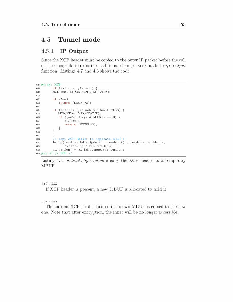
4.5. Tunnel mode 53
4.5 Tunnel mode
4.5.1 IP Output
Since the XCP header must be copied to the outer IP packet before the callof the encapsulation routines, aditional changes were made to ip6 outputfunction. Listings 4.7 and 4.8 shows the code.
647#i f d e f XCP648 i f ( exthdrs . ip6e xch ) {649 MGET(mx, M DONTWAIT, MTDATA) ;650
651 i f ( !mx)652 r e turn (ENOBUFS) ;653
654 i f ( exthdrs . ip6e xch−>m len > MLEN) {655 MCLGET(m, MDONTWAIT) ;656 i f ( (m−>m f lags & M EXT) == 0) {657 m free (m) ;658 r e turn (ENOBUFS) ;659 }660 }661 }662 /∗ copy XCP Header to s epara t e mbuf ∗/663 bcopy (mtod( exthdrs . ip6e xch , caddr t ) , mtod(mx, caddr t ) ,664 exthdrs . ip6e xch−>m len ) ;665 mx−>m len += exthdrs . ip6e xch−>m len ;666#end i f /∗ XCP ∗/
Listing 4.7: netinet6/ip6 output.c copy the XCP header to a temporaryMBUF
647 - 660
If XCP header is present, a new MBUF is allocated to hold it.
663 - 665
The current XCP header located in its own MBUF is copied to the newone. Note that after encryption, the inner will be no longer accessible.
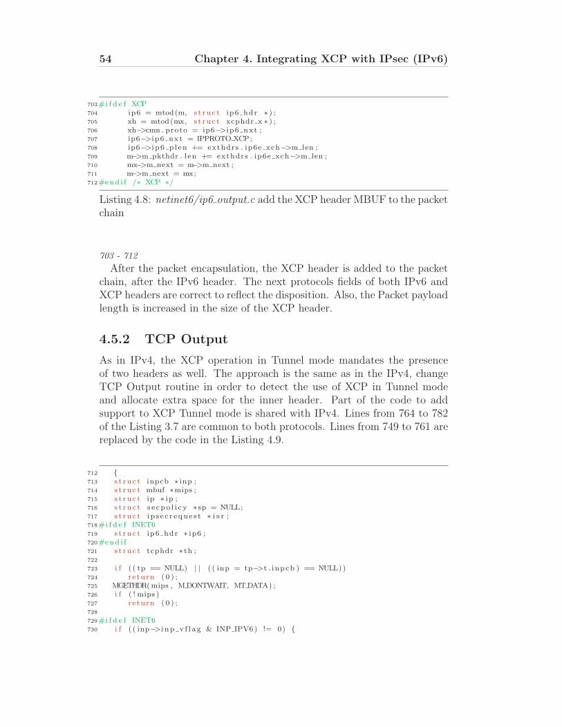
54 Chapter 4. Integrating XCP with IPsec (IPv6)
703#i f d e f XCP704 ip6 = mtod(m, s t r u c t ip6 hdr ∗ ) ;705 xh = mtod(mx, s t r u c t xcphdr x ∗ ) ;706 xh−>cmn . proto = ip6−>i p6 nxt ;707 ip6−>i p6 nxt = IPPROTO XCP;708 ip6−>i p 6 p l en += exthdrs . ip6e xch−>m len ;709 m−>m pkthdr . l en += exthdrs . ip6e xch−>m len ;710 mx−>m next = m−>m next ;711 m−>m next = mx;712#end i f /∗ XCP ∗/
Listing 4.8: netinet6/ip6 output.c add the XCP header MBUF to the packetchain
703 - 712
After the packet encapsulation, the XCP header is added to the packetchain, after the IPv6 header. The next protocols fields of both IPv6 andXCP headers are correct to reflect the disposition. Also, the Packet payloadlength is increased in the size of the XCP header.
4.5.2 TCP Output
As in IPv4, the XCP operation in Tunnel mode mandates the presenceof two headers as well. The approach is the same as in the IPv4, changeTCP Output routine in order to detect the use of XCP in Tunnel modeand allocate extra space for the inner header. Part of the code to addsupport to XCP Tunnel mode is shared with IPv4. Lines from 764 to 782of the Listing 3.7 are common to both protocols. Lines from 749 to 761 arereplaced by the code in the Listing 4.9.
712 {713 s t r u c t inpcb ∗ inp ;714 s t r u c t mbuf ∗mips ;715 s t r u c t ip ∗ ip ;716 s t r u c t s e c p o l i c y ∗ sp = NULL;717 s t r u c t i p s e c r e qu e s t ∗ i s r ;718#i f d e f INET6719 s t r u c t ip6 hdr ∗ ip6 ;720#end i f721 s t r u c t tcphdr ∗ th ;722
723 i f ( ( tp == NULL) | | ( ( inp = tp−>t inpcb ) == NULL) )724 r e turn ( 0 ) ;725 MGETHDR(mips , M DONTWAIT, MTDATA) ;726 i f ( ! mips )727 r e turn ( 0 ) ;728
729#i f d e f INET6730 i f ( ( inp−>i n p v f l a g & INP IPV6) != 0) {
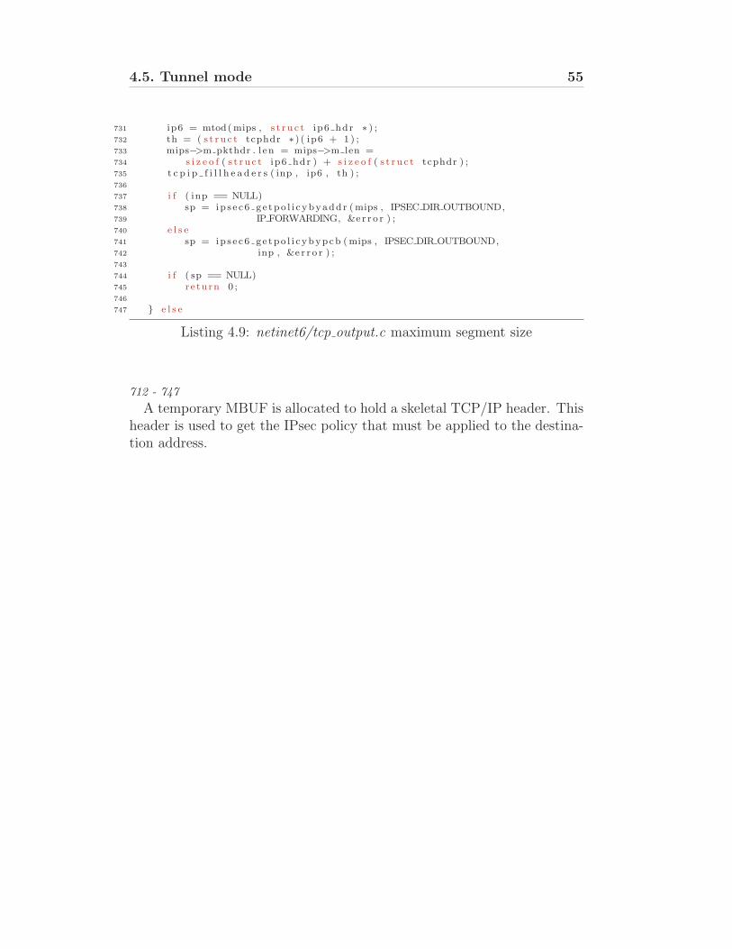
4.5. Tunnel mode 55
731 ip6 = mtod(mips , s t r u c t ip6 hdr ∗ ) ;732 th = ( s t r u c t tcphdr ∗ ) ( ip6 + 1 ) ;733 mips−>m pkthdr . l en = mips−>m len =734 s i z e o f ( s t r u c t ip6 hdr ) + s i z e o f ( s t r u c t tcphdr ) ;735 t c p i p f i l l h e a d e r s ( inp , ip6 , th ) ;736
737 i f ( inp == NULL)738 sp = ip s e c6 g e tpo l i c ybyadd r (mips , IPSEC DIR OUTBOUND,739 IP FORWARDING, &e r r o r ) ;740 e l s e741 sp = ip s e c6 ge tpo l i c ybypcb (mips , IPSEC DIR OUTBOUND,742 inp , &e r r o r ) ;743
744 i f ( sp == NULL)745 r e turn 0 ;746
747 } e l s e
Listing 4.9: netinet6/tcp output.c maximum segment size
712 - 747
A temporary MBUF is allocated to hold a skeletal TCP/IP header. Thisheader is used to get the IPsec policy that must be applied to the destina-tion address.

Chapter 5
Results
This chapter presents the results obtained in the use of the integration ofXCP with IPsec. Sections 5.2 through 5.5 show connectivity tests usingthe several combinations of IPsec security services and IP versions. Thefinal section presents a performance test for both data rate and packetprocessing time.
5.1 Testbed Setup
The testbed was composed by three end-hosts in different subnets con-nected by one intermediate router. All nodes were equipped with a 100Mbit/scapable network interface card, a Pentium-3 733MHz CPU and 512 MB ofRAM. The objective of all subsequent test scenarios was to establish a suc-cessful connection between a client and the sink for both IPv4 and IPv6.Results were obtained using wireshark [18], a protocol dissector, runningon R1, with both the libcrypt library for packet decryption and validationand a patch for XCP header detection which it was developed.
All traffic was generated using XCP test tools, namely xstream andxserver, which provided respectively both client and server applicationsfor communicating over XCP sockets. Prior to all tests, IPsec policies(SAD and SPD) on both end-hosts were adjusted to reflect the appropriatescenario settings.
57
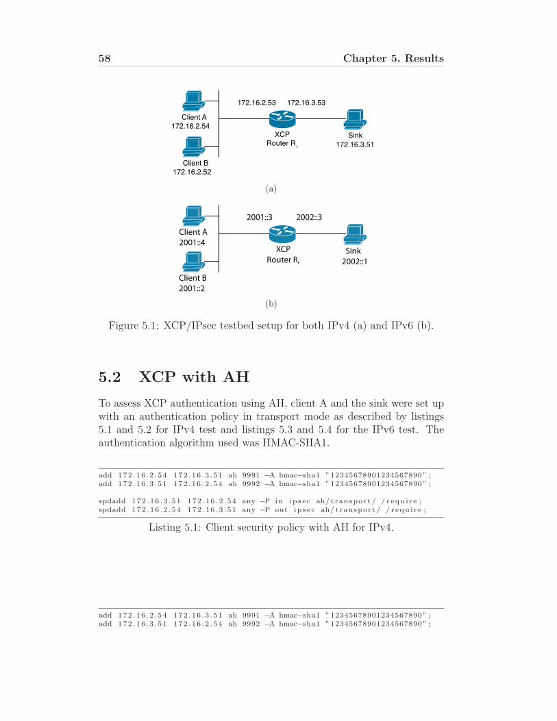
58 Chapter 5. Results
Client A
XCP Router R₁
172.16.2.54Sink
172.16.3.51
172.16.3.53172.16.2.53
Client B172.16.2.52
(a)
Client A
2001::4
Client B
2001::2
2001::3 2002::3
XCP
Router R, Sink
2002::1
(b)
Figure 5.1: XCP/IPsec testbed setup for both IPv4 (a) and IPv6 (b).
5.2 XCP with AH
To assess XCP authentication using AH, client A and the sink were set upwith an authentication policy in transport mode as described by listings5.1 and 5.2 for IPv4 test and listings 5.3 and 5.4 for the IPv6 test. Theauthentication algorithm used was HMAC-SHA1.
add 172 . 1 6 . 2 . 5 4 172 . 1 6 . 3 . 5 1 ah 9991 −A hmac−sha1 ”12345678901234567890” ;add 172 . 1 6 . 3 . 5 1 172 . 1 6 . 2 . 5 4 ah 9992 −A hmac−sha1 ”12345678901234567890” ;
spdadd 172 . 1 6 . 3 . 5 1 172 . 1 6 . 2 . 5 4 any −P in i p s e c ah/ t ranspor t / / r e qu i r e ;spdadd 172 . 1 6 . 2 . 5 4 172 . 1 6 . 3 . 5 1 any −P out i p s e c ah/ t ranspor t / / r e qu i r e ;
Listing 5.1: Client security policy with AH for IPv4.
add 172 . 1 6 . 2 . 5 4 172 . 1 6 . 3 . 5 1 ah 9991 −A hmac−sha1 ”12345678901234567890” ;add 172 . 1 6 . 3 . 5 1 172 . 1 6 . 2 . 5 4 ah 9992 −A hmac−sha1 ”12345678901234567890” ;
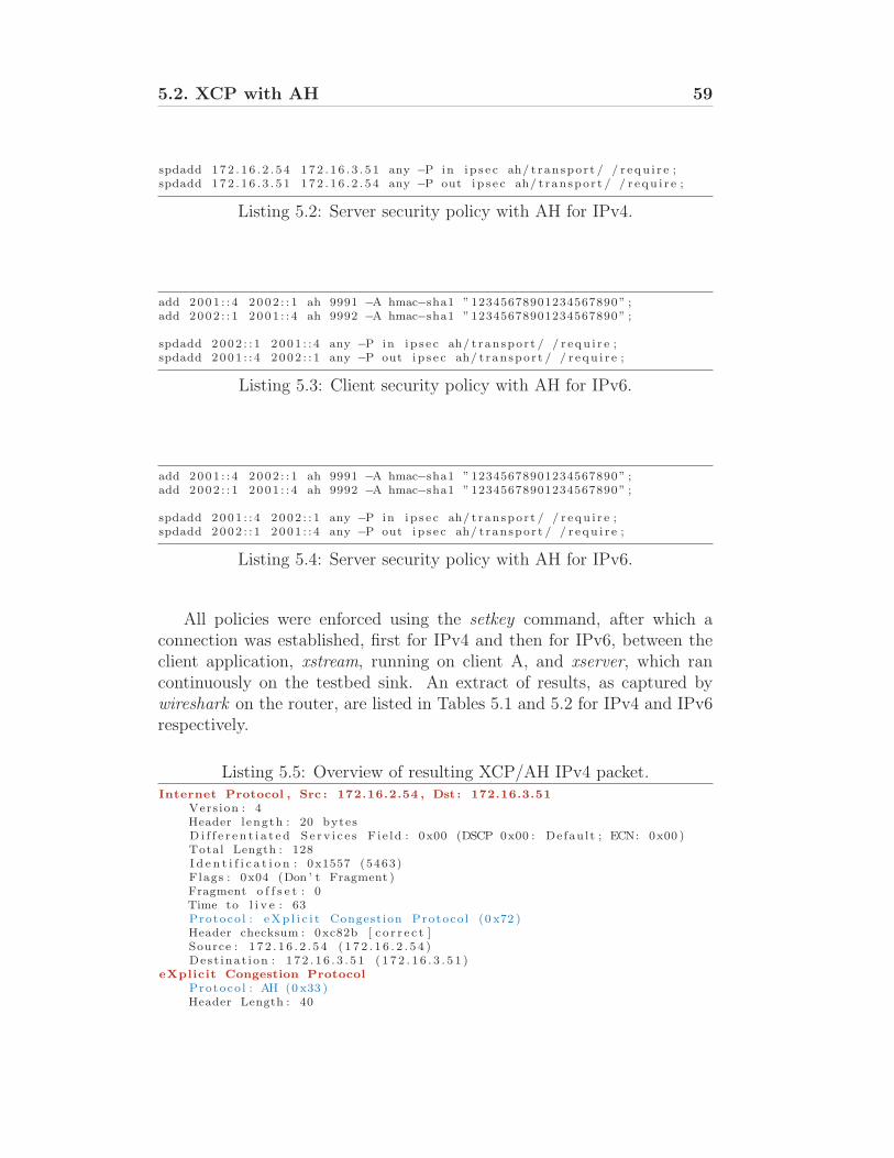
5.2. XCP with AH 59
spdadd 172 . 1 6 . 2 . 5 4 172 . 1 6 . 3 . 5 1 any −P in i p s e c ah/ t ranspor t / / r e qu i r e ;spdadd 172 . 1 6 . 3 . 5 1 172 . 1 6 . 2 . 5 4 any −P out i p s e c ah/ t ranspor t / / r e qu i r e ;
Listing 5.2: Server security policy with AH for IPv4.
add 2001 : : 4 2002 : : 1 ah 9991 −A hmac−sha1 ”12345678901234567890” ;add 2002 : : 1 2001 : : 4 ah 9992 −A hmac−sha1 ”12345678901234567890” ;
spdadd 2002 : : 1 2001 : : 4 any −P in i p s e c ah/ t ranspor t / / r e qu i r e ;spdadd 2001 : : 4 2002 : : 1 any −P out i p s e c ah/ t ranspor t / / r e qu i r e ;
Listing 5.3: Client security policy with AH for IPv6.
add 2001 : : 4 2002 : : 1 ah 9991 −A hmac−sha1 ”12345678901234567890” ;add 2002 : : 1 2001 : : 4 ah 9992 −A hmac−sha1 ”12345678901234567890” ;
spdadd 2001 : : 4 2002 : : 1 any −P in i p s e c ah/ t ranspor t / / r e qu i r e ;spdadd 2002 : : 1 2001 : : 4 any −P out i p s e c ah/ t ranspor t / / r e qu i r e ;
Listing 5.4: Server security policy with AH for IPv6.
All policies were enforced using the setkey command, after which aconnection was established, first for IPv4 and then for IPv6, between theclient application, xstream, running on client A, and xserver, which rancontinuously on the testbed sink. An extract of results, as captured bywireshark on the router, are listed in Tables 5.1 and 5.2 for IPv4 and IPv6respectively.
Listing 5.5: Overview of resulting XCP/AH IPv4 packet.Internet Protocol , Src : 172.16.2.54 , Dst : 172.16.3.51
Vers ion : 4Header l ength : 20 bytesD i f f e r e n t i a t e d S e r v i c e s F i e ld : 0x00 (DSCP 0x00 : Defau l t ; ECN: 0x00 )Total Length : 128I d e n t i f i c a t i o n : 0x1557 (5463)Flags : 0x04 (Don ’ t Fragment )Fragment o f f s e t : 0Time to l i v e : 63Protoco l : eXp l i c i t Congest ion Protoco l (0 x72 )Header checksum : 0xc82b [ c o r r e c t ]Source : 1 7 2 . 1 6 . 2 . 5 4 ( 1 7 2 . 1 6 . 2 . 5 4 )Des t inat i on : 1 7 2 . 1 6 . 3 . 5 1 ( 1 7 2 . 1 6 . 3 . 5 1 )
eXplicit Congestion Protocol
Protoco l : AH (0 x33 )Header Length : 40
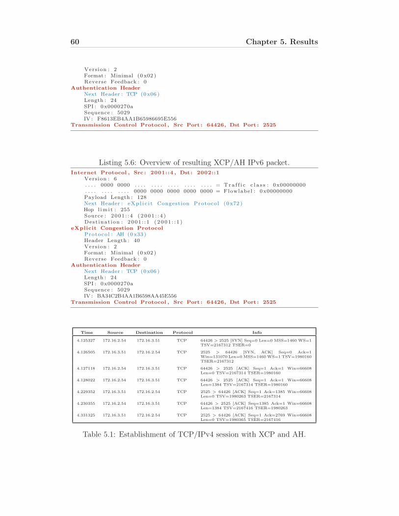
60 Chapter 5. Results
Vers ion : 2Format : Minimal (0 x02 )Reverse Feedback : 0
Authentication Header
Next Header : TCP (0 x06 )Length : 24SPI : 0x0000270aSequence : 5029IV : F8613EB4AA1B65986695E556
Transmission Control Protocol , Src Port : 64426, Dst Port : 2525
Listing 5.6: Overview of resulting XCP/AH IPv6 packet.Internet Protocol , Src : 2001::4 , Dst : 2002::1
Vers ion : 6. . . . 0000 0000 . . . . . . . . . . . . . . . . . . . . = T r a f f i c c l a s s : 0x00000000. . . . . . . . . . . . 0000 0000 0000 0000 0000 = Flowlabe l : 0x00000000Payload Length : 128Next Header : eXp l i c i t Congest ion Protoco l (0 x72 )Hop l im i t : 255Source : 2 001 : : 4 ( 2 0 0 1 : : 4 )Des t inat i on : 2 001 : : 1 ( 2 0 0 1 : : 1 )
eXplicit Congestion Protocol
Protoco l : AH (0 x33 )Header Length : 40Vers ion : 2Format : Minimal (0 x02 )Reverse Feedback : 0
Authentication Header
Next Header : TCP (0 x06 )Length : 24SPI : 0x0000270aSequence : 5029IV : BA34C2B4AA1B6598AA45E556
Transmission Control Protocol , Src Port : 64426, Dst Port : 2525
Time Source Destination Protocol Info
4.125327 172.16.2.54 172.16.3.51 TCP 64426 > 2525 [SYN] Seq=0 Len=0 MSS=1460 WS=1TSV=2167312 TSER=0
4.126505 172.16.3.51 172.16.2.54 TCP 2525 > 64426 [SYN, ACK] Seq=0 Ack=1Win=131070 Len=0 MSS=1460 WS=1 TSV=1980160TSER=2167312
4.127118 172.16.2.54 172.16.3.51 TCP 64426 > 2525 [ACK] Seq=1 Ack=1 Win=66608Len=0 TSV=2167314 TSER=1980160
4.128022 172.16.2.54 172.16.3.51 TCP 64426 > 2525 [ACK] Seq=1 Ack=1 Win=66608Len=1384 TSV=2167314 TSER=1980160
4.229352 172.16.3.51 172.16.2.54 TCP 2525 > 64426 [ACK] Seq=1 Ack=1385 Win=66608Len=0 TSV=1980263 TSER=2167314
4.230355 172.16.2.54 172.16.3.51 TCP 64426 > 2525 [ACK] Seq=1385 Ack=1 Win=66608Len=1384 TSV=2167416 TSER=1980263
4.331325 172.16.3.51 172.16.2.54 TCP 2525 > 64426 [ACK] Seq=1 Ack=2769 Win=66608Len=0 TSV=1980365 TSER=2167416
Table 5.1: Establishment of TCP/IPv4 session with XCP and AH.
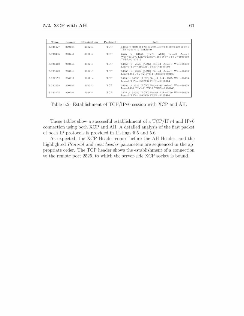
5.2. XCP with AH 61
Time Source Destination Protocol Info
3.125427 2001::4 2002::1 TCP 34656 > 2525 [SYN] Seq=0 Len=0 MSS=1460 WS=1TSV=2167312 TSER=0
3.126305 2002::1 2001::4 TCP 2525 > 34656 [SYN, ACK] Seq=0 Ack=1Win=131070 Len=0 MSS=1460 WS=1 TSV=1980160TSER=2167312
3.127418 2001::4 2002::1 TCP 34656 > 2525 [ACK] Seq=1 Ack=1 Win=66608Len=0 TSV=2167314 TSER=1980160
3.128422 2001::4 2002::1 TCP 34656 > 2525 [ACK] Seq=1 Ack=1 Win=66608Len=1384 TSV=2167314 TSER=1980160
3.229152 2002::1 2001::4 TCP 2525 > 34656 [ACK] Seq=1 Ack=1385 Win=66608Len=0 TSV=1980263 TSER=2167314
3.230255 2001::4 2002::1 TCP 34656 > 2525 [ACK] Seq=1385 Ack=1 Win=66608Len=1384 TSV=2167416 TSER=1980263
3.331425 2002::1 2001::4 TCP 2525 > 34656 [ACK] Seq=1 Ack=2769 Win=66608Len=0 TSV=1980365 TSER=2167416
Table 5.2: Establishment of TCP/IPv6 session with XCP and AH.
These tables show a successful establishment of a TCP/IPv4 and IPv6connection using both XCP and AH. A detailed analysis of the first packetof both IP protocols is provided in Listings 5.5 and 5.6.
As expected, the XCP Header comes before the AH Header, and thehighlighted Protocol and next header parameters are sequenced in the ap-propriate order. The TCP header shows the establishment of a connectionto the remote port 2525, to which the server-side XCP socket is bound.
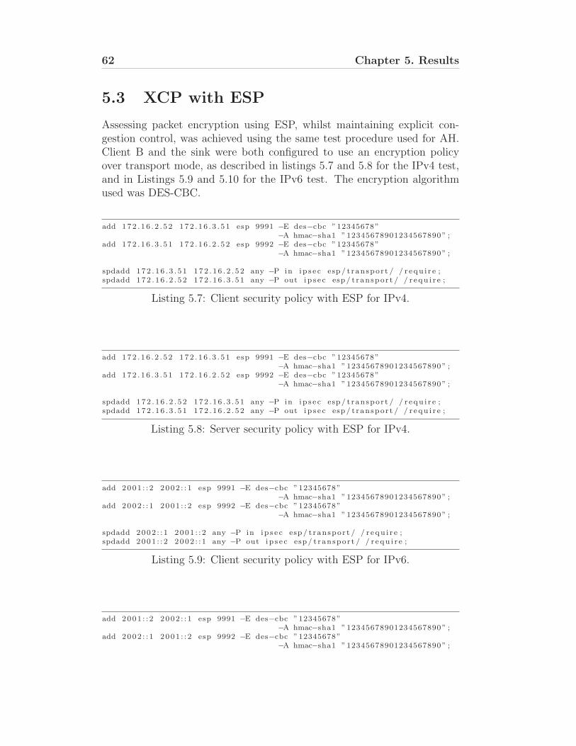
62 Chapter 5. Results
5.3 XCP with ESP
Assessing packet encryption using ESP, whilst maintaining explicit con-gestion control, was achieved using the same test procedure used for AH.Client B and the sink were both configured to use an encryption policyover transport mode, as described in listings 5.7 and 5.8 for the IPv4 test,and in Listings 5.9 and 5.10 for the IPv6 test. The encryption algorithmused was DES-CBC.
add 172 . 1 6 . 2 . 5 2 172 . 1 6 . 3 . 5 1 esp 9991 −E des−cbc ”12345678”−A hmac−sha1 ”12345678901234567890” ;
add 172 . 1 6 . 3 . 5 1 172 . 1 6 . 2 . 5 2 esp 9992 −E des−cbc ”12345678”−A hmac−sha1 ”12345678901234567890” ;
spdadd 172 . 1 6 . 3 . 5 1 172 . 1 6 . 2 . 5 2 any −P in i p s e c esp / t ranspor t / / r e qu i r e ;spdadd 172 . 1 6 . 2 . 5 2 172 . 1 6 . 3 . 5 1 any −P out i p s e c esp / t ranspor t / / r e qu i r e ;
Listing 5.7: Client security policy with ESP for IPv4.
add 172 . 1 6 . 2 . 5 2 172 . 1 6 . 3 . 5 1 esp 9991 −E des−cbc ”12345678”−A hmac−sha1 ”12345678901234567890” ;
add 172 . 1 6 . 3 . 5 1 172 . 1 6 . 2 . 5 2 esp 9992 −E des−cbc ”12345678”−A hmac−sha1 ”12345678901234567890” ;
spdadd 172 . 1 6 . 2 . 5 2 172 . 1 6 . 3 . 5 1 any −P in i p s e c esp / t ranspor t / / r e qu i r e ;spdadd 172 . 1 6 . 3 . 5 1 172 . 1 6 . 2 . 5 2 any −P out i p s e c esp / t ranspor t / / r e qu i r e ;
Listing 5.8: Server security policy with ESP for IPv4.
add 2001 : : 2 2002 : : 1 esp 9991 −E des−cbc ”12345678”−A hmac−sha1 ”12345678901234567890” ;
add 2002 : : 1 2001 : : 2 esp 9992 −E des−cbc ”12345678”−A hmac−sha1 ”12345678901234567890” ;
spdadd 2002 : : 1 2001 : : 2 any −P in i p s e c esp / t ranspor t / / r e qu i r e ;spdadd 2001 : : 2 2002 : : 1 any −P out i p s e c esp / t ranspor t / / r e qu i r e ;
Listing 5.9: Client security policy with ESP for IPv6.
add 2001 : : 2 2002 : : 1 esp 9991 −E des−cbc ”12345678”−A hmac−sha1 ”12345678901234567890” ;
add 2002 : : 1 2001 : : 2 esp 9992 −E des−cbc ”12345678”−A hmac−sha1 ”12345678901234567890” ;
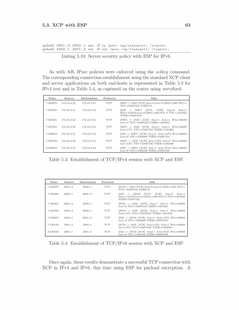
5.3. XCP with ESP 63
spdadd 2001 : : 2 2002 : : 1 any −P in i p s e c esp / t ranspor t / / r e qu i r e ;spdadd 2002 : : 1 2001 : : 2 any −P out i p s e c esp / t ranspor t / / r e qu i r e ;
Listing 5.10: Server security policy with ESP for IPv6.
As with AH, IPsec policies were enforced using the setkey command.The corresponding connection establishment using the standard XCP clientand server applications on both end-hosts is represented in Table 5.3 forIPv4 test and in Table 5.4, as captured on the router using wireshark.
Time Source Destination Protocol Info
7.824979 172.16.2.52 172.16.3.51 TCP 50871 > 2525 [SYN] Seq=0 Len=0 MSS=1460 WS=1TSV=55897432 TSER=0
7.825695 172.16.3.51 172.16.2.52 TCP 2525 > 50871 [SYN, ACK] Seq=0 Ack=1Win=131070 Len=0 MSS=1460 WS=1 TSV=1581962TSER=55897432
7.826461 172.16.2.52 172.16.3.51 TCP 50871 > 2525 [ACK] Seq=1 Ack=1 Win=66608Len=0 TSV=55897434 TSER=1581962
7.827945 172.16.2.52 172.16.3.51 TCP 50871 > 2525 [ACK] Seq=1 Ack=1 Win=66608Len=1371 TSV=55897434 TSER=1581962
7.928693 172.16.3.51 172.16.2.52 TCP 2525 > 50871 [ACK] Seq=1 Ack=1372 Win=66608Len=0 TSV=1582066 TSER=55897434
7.930192 172.16.2.52 172.16.3.51 TCP 50871 > 2525 [ACK] Seq=1372 Ack=1 Win=66608Len=1371 TSV=55897536 TSER=1582066
8.030639 172.16.3.51 172.16.2.52 TCP 2525 > 50871 [ACK] Seq=1 Ack=2743 Win=66608Len=0 TSV=1582168 TSER=55897536
Table 5.3: Establishment of TCP/IPv4 session with XCP and ESP.
Time Source Destination Protocol Info
7.424979 2001::2 2002::1 TCP 28743 > 2525 [SYN] Seq=0 Len=0 MSS=1460 WS=1TSV=55897432 TSER=0
7.425695 2002::1 2001::2 TCP 2525 > 28743 [SYN, ACK] Seq=0 Ack=1Win=131070 Len=0 MSS=1460 WS=1 TSV=1581962TSER=55897432
7.426461 2001::2 2002::1 TCP 28743 > 2525 [ACK] Seq=1 Ack=1 Win=66608Len=0 TSV=55897434 TSER=1581962
7.427945 2001::2 2002::1 TCP 28743 > 2525 [ACK] Seq=1 Ack=1 Win=66608Len=1371 TSV=55897434 TSER=1581962
7.528693 2002::1 2001::2 TCP 2525 > 28743 [ACK] Seq=1 Ack=1372 Win=66608Len=0 TSV=1582066 TSER=55897434
7.530192 2001::2 2002::1 TCP 28743 > 2525 [ACK] Seq=1372 Ack=1 Win=66608Len=1371 TSV=55897536 TSER=1582066
8.630639 2002::1 2001::2 TCP 2525 > 28743 [ACK] Seq=1 Ack=2743 Win=66608Len=0 TSV=1582168 TSER=55897536
Table 5.4: Establishment of TCP/IPv6 session with XCP and ESP.
Once again, these results demonstrate a successful TCP connection withXCP in IPv4 and IPv6, this time using ESP for payload encryption. A
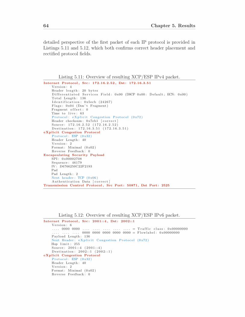
64 Chapter 5. Results
detailed perspective of the first packet of each IP protocol is provided inListings 5.11 and 5.12, which both confirms correct header placement andrectified protocol fields.
Listing 5.11: Overview of resulting XCP/ESP IPv4 packet.Internet Protocol , Src : 172.16.2.52 , Dst : 172.16.3.51
Vers ion : 4Header l ength : 20 bytesD i f f e r e n t i a t e d S e r v i c e s F i e ld : 0x00 (DSCP 0x00 : Defau l t ; ECN: 0x00 )Total Length : 136I d e n t i f i c a t i o n : 0x5ecb (24267)Flags : 0x04 (Don ’ t Fragment )Fragment o f f s e t : 0Time to l i v e : 63Protoco l : eXp l i c i t Congest ion Protoco l (0 x72 )Header checksum : 0x7eb1 [ c o r r e c t ]Source : 1 7 2 . 1 6 . 2 . 5 2 ( 1 7 2 . 1 6 . 2 . 5 2 )Des t inat i on : 1 7 2 . 1 6 . 3 . 5 1 ( 1 7 2 . 1 6 . 3 . 5 1 )
eXplicit Congestion Protocol
Protoco l : ESP (0 x32 )Header Length : 40Vers ion : 2Format : Minimal (0 x02 )Reverse Feedback : 0
Encapsulating Security Payload
SPI : 0x00002708Sequence : 46179IV : D6766250C22F2193PadPad Length : 2Next header : TCP (0 x06 )Authent icat ion Data [ c o r r e c t ]
Transmission Control Protocol , Src Port : 50871, Dst Port : 2525
Listing 5.12: Overview of resulting XCP/ESP IPv6 packet.Internet Protocol , Src : 2001::4 , Dst : 2002::1
Vers ion : 6. . . . 0000 0000 . . . . . . . . . . . . . . . . . . . . = T r a f f i c c l a s s : 0x00000000. . . . . . . . . . . . 0000 0000 0000 0000 0000 = Flowlabe l : 0x00000000Payload Length : 136Next Header : eXp l i c i t Congest ion Protoco l (0 x72 )Hop l im i t : 255Source : 2 001 : : 4 ( 2 0 0 1 : : 4 )Des t inat i on : 2 002 : : 1 ( 2 0 0 2 : : 1 )
eXplicit Congestion Protocol
Protoco l : ESP (0 x32 )Header Length : 40Vers ion : 2Format : Minimal (0 x02 )Reverse Feedback : 0
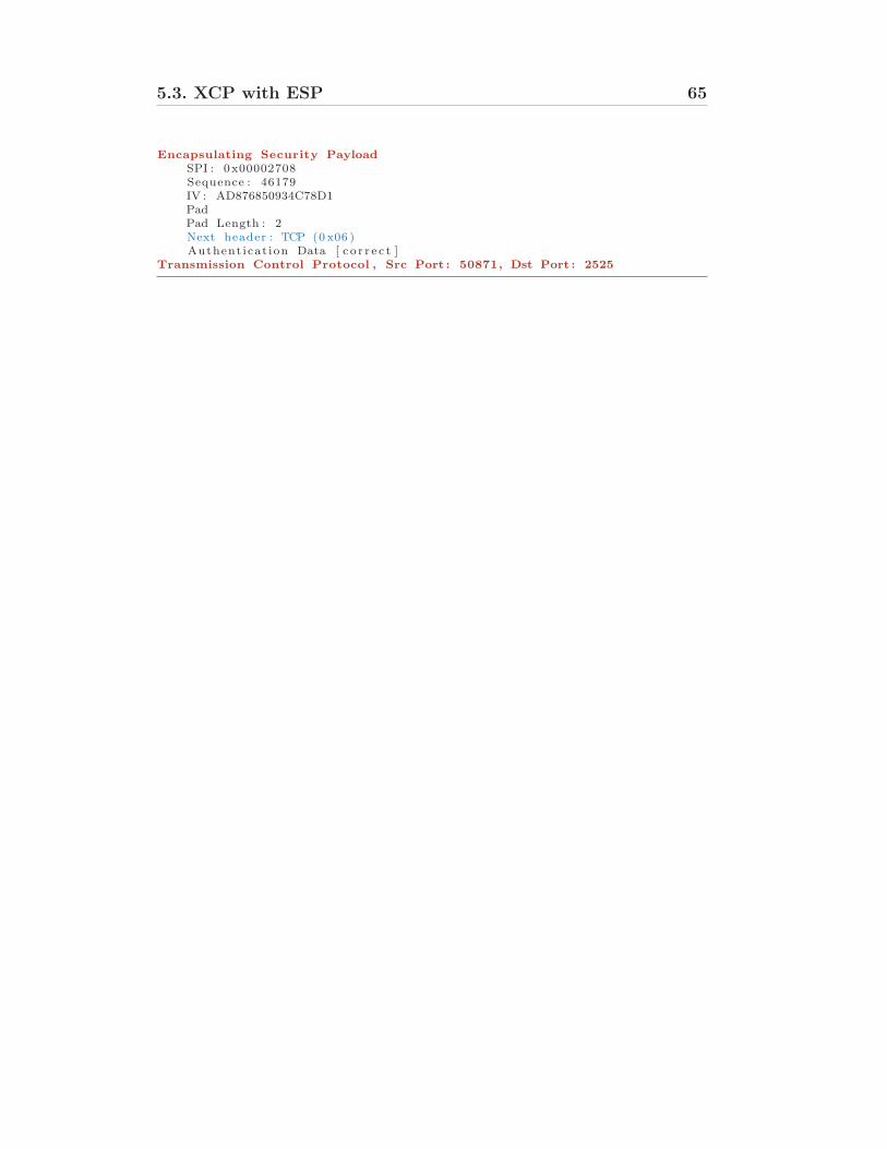
5.3. XCP with ESP 65
Encapsulating Security Payload
SPI : 0x00002708Sequence : 46179IV : AD876850934C78D1PadPad Length : 2Next header : TCP (0 x06 )Authent icat ion Data [ c o r r e c t ]
Transmission Control Protocol , Src Port : 50871, Dst Port : 2525
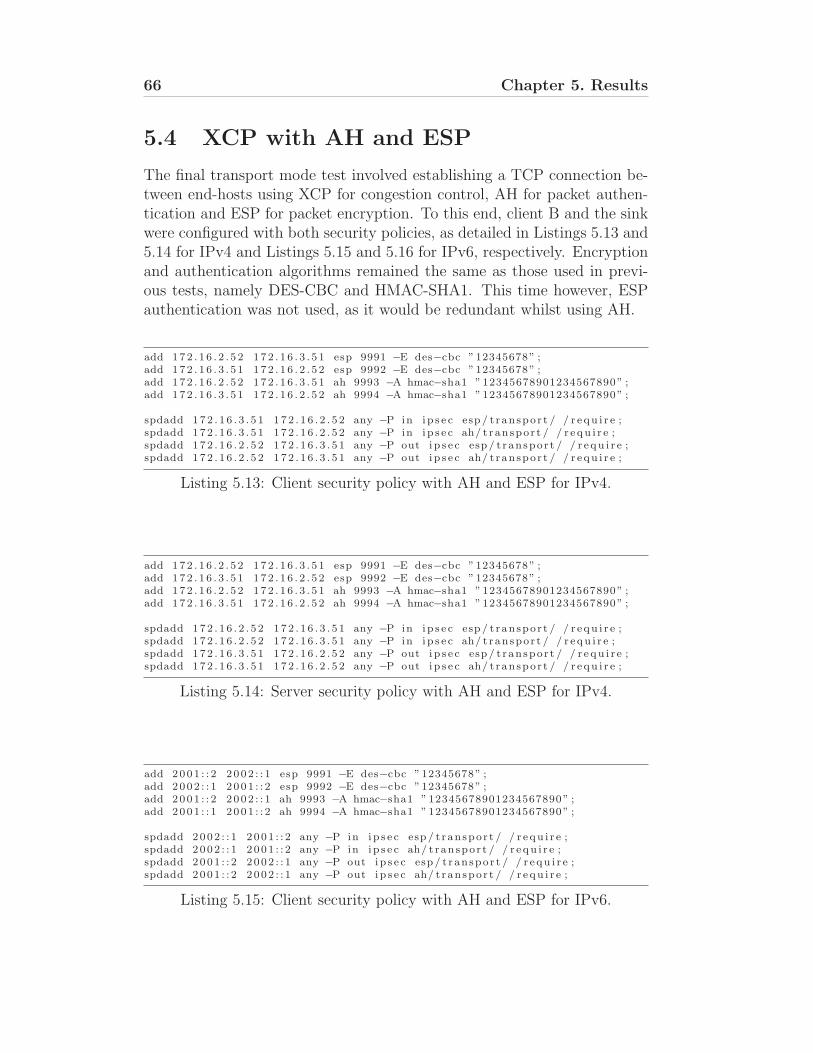
66 Chapter 5. Results
5.4 XCP with AH and ESP
The final transport mode test involved establishing a TCP connection be-tween end-hosts using XCP for congestion control, AH for packet authen-tication and ESP for packet encryption. To this end, client B and the sinkwere configured with both security policies, as detailed in Listings 5.13 and5.14 for IPv4 and Listings 5.15 and 5.16 for IPv6, respectively. Encryptionand authentication algorithms remained the same as those used in previ-ous tests, namely DES-CBC and HMAC-SHA1. This time however, ESPauthentication was not used, as it would be redundant whilst using AH.
add 172 . 1 6 . 2 . 5 2 172 . 1 6 . 3 . 5 1 esp 9991 −E des−cbc ”12345678” ;add 172 . 1 6 . 3 . 5 1 172 . 1 6 . 2 . 5 2 esp 9992 −E des−cbc ”12345678” ;add 172 . 1 6 . 2 . 5 2 172 . 1 6 . 3 . 5 1 ah 9993 −A hmac−sha1 ”12345678901234567890” ;add 172 . 1 6 . 3 . 5 1 172 . 1 6 . 2 . 5 2 ah 9994 −A hmac−sha1 ”12345678901234567890” ;
spdadd 172 . 1 6 . 3 . 5 1 172 . 1 6 . 2 . 5 2 any −P in i p s e c esp / t ranspor t / / r e qu i r e ;spdadd 172 . 1 6 . 3 . 5 1 172 . 1 6 . 2 . 5 2 any −P in i p s e c ah/ t ranspor t / / r e qu i r e ;spdadd 172 . 1 6 . 2 . 5 2 172 . 1 6 . 3 . 5 1 any −P out i p s e c esp / t ranspor t / / r e qu i r e ;spdadd 172 . 1 6 . 2 . 5 2 172 . 1 6 . 3 . 5 1 any −P out i p s e c ah/ t ranspor t / / r e qu i r e ;
Listing 5.13: Client security policy with AH and ESP for IPv4.
add 172 . 1 6 . 2 . 5 2 172 . 1 6 . 3 . 5 1 esp 9991 −E des−cbc ”12345678” ;add 172 . 1 6 . 3 . 5 1 172 . 1 6 . 2 . 5 2 esp 9992 −E des−cbc ”12345678” ;add 172 . 1 6 . 2 . 5 2 172 . 1 6 . 3 . 5 1 ah 9993 −A hmac−sha1 ”12345678901234567890” ;add 172 . 1 6 . 3 . 5 1 172 . 1 6 . 2 . 5 2 ah 9994 −A hmac−sha1 ”12345678901234567890” ;
spdadd 172 . 1 6 . 2 . 5 2 172 . 1 6 . 3 . 5 1 any −P in i p s e c esp / t ranspor t / / r e qu i r e ;spdadd 172 . 1 6 . 2 . 5 2 172 . 1 6 . 3 . 5 1 any −P in i p s e c ah/ t ranspor t / / r e qu i r e ;spdadd 172 . 1 6 . 3 . 5 1 172 . 1 6 . 2 . 5 2 any −P out i p s e c esp / t ranspor t / / r e qu i r e ;spdadd 172 . 1 6 . 3 . 5 1 172 . 1 6 . 2 . 5 2 any −P out i p s e c ah/ t ranspor t / / r e qu i r e ;
Listing 5.14: Server security policy with AH and ESP for IPv4.
add 2001 : : 2 2002 : : 1 esp 9991 −E des−cbc ”12345678” ;add 2002 : : 1 2001 : : 2 esp 9992 −E des−cbc ”12345678” ;add 2001 : : 2 2002 : : 1 ah 9993 −A hmac−sha1 ”12345678901234567890” ;add 2001 : : 1 2001 : : 2 ah 9994 −A hmac−sha1 ”12345678901234567890” ;
spdadd 2002 : : 1 2001 : : 2 any −P in i p s e c esp / t ranspor t / / r e qu i r e ;spdadd 2002 : : 1 2001 : : 2 any −P in i p s e c ah/ t ranspor t / / r e qu i r e ;spdadd 2001 : : 2 2002 : : 1 any −P out i p s e c esp / t ranspor t / / r e qu i r e ;spdadd 2001 : : 2 2002 : : 1 any −P out i p s e c ah/ t ranspor t / / r e qu i r e ;
Listing 5.15: Client security policy with AH and ESP for IPv6.
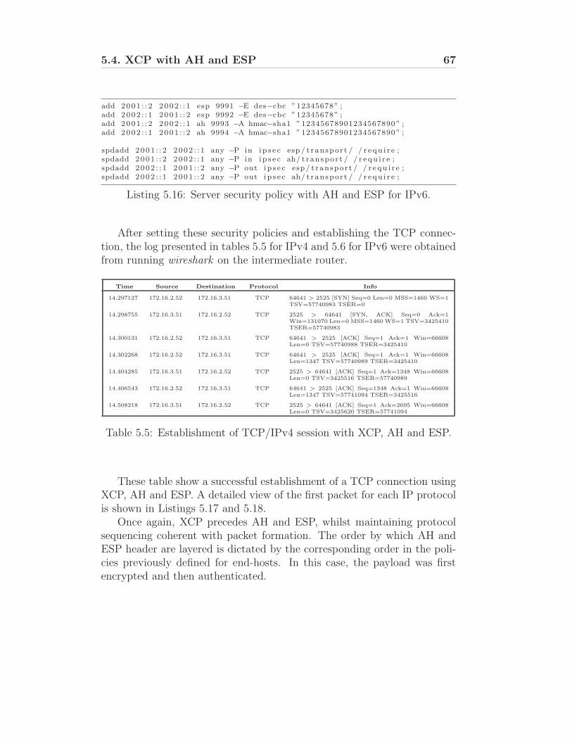
5.4. XCP with AH and ESP 67
add 2001 : : 2 2002 : : 1 esp 9991 −E des−cbc ”12345678” ;add 2002 : : 1 2001 : : 2 esp 9992 −E des−cbc ”12345678” ;add 2001 : : 2 2002 : : 1 ah 9993 −A hmac−sha1 ”12345678901234567890” ;add 2002 : : 1 2001 : : 2 ah 9994 −A hmac−sha1 ”12345678901234567890” ;
spdadd 2001 : : 2 2002 : : 1 any −P in i p s e c esp / t ranspor t / / r e qu i r e ;spdadd 2001 : : 2 2002 : : 1 any −P in i p s e c ah/ t ranspor t / / r e qu i r e ;spdadd 2002 : : 1 2001 : : 2 any −P out i p s e c esp / t ranspor t / / r e qu i r e ;spdadd 2002 : : 1 2001 : : 2 any −P out i p s e c ah/ t ranspor t / / r e qu i r e ;
Listing 5.16: Server security policy with AH and ESP for IPv6.
After setting these security policies and establishing the TCP connec-tion, the log presented in tables 5.5 for IPv4 and 5.6 for IPv6 were obtainedfrom running wireshark on the intermediate router.
Time Source Destination Protocol Info
14.297127 172.16.2.52 172.16.3.51 TCP 64641 > 2525 [SYN] Seq=0 Len=0 MSS=1460 WS=1TSV=57740983 TSER=0
14.298755 172.16.3.51 172.16.2.52 TCP 2525 > 64641 [SYN, ACK] Seq=0 Ack=1Win=131070 Len=0 MSS=1460 WS=1 TSV=3425410TSER=57740983
14.300131 172.16.2.52 172.16.3.51 TCP 64641 > 2525 [ACK] Seq=1 Ack=1 Win=66608Len=0 TSV=57740988 TSER=3425410
14.302268 172.16.2.52 172.16.3.51 TCP 64641 > 2525 [ACK] Seq=1 Ack=1 Win=66608Len=1347 TSV=57740989 TSER=3425410
14.404285 172.16.3.51 172.16.2.52 TCP 2525 > 64641 [ACK] Seq=1 Ack=1348 Win=66608Len=0 TSV=3425516 TSER=57740989
14.406543 172.16.2.52 172.16.3.51 TCP 64641 > 2525 [ACK] Seq=1348 Ack=1 Win=66608Len=1347 TSV=57741094 TSER=3425516
14.508218 172.16.3.51 172.16.2.52 TCP 2525 > 64641 [ACK] Seq=1 Ack=2695 Win=66608Len=0 TSV=3425620 TSER=57741094
Table 5.5: Establishment of TCP/IPv4 session with XCP, AH and ESP.
These table show a successful establishment of a TCP connection usingXCP, AH and ESP. A detailed view of the first packet for each IP protocolis shown in Listings 5.17 and 5.18.
Once again, XCP precedes AH and ESP, whilst maintaining protocolsequencing coherent with packet formation. The order by which AH andESP header are layered is dictated by the corresponding order in the poli-cies previously defined for end-hosts. In this case, the payload was firstencrypted and then authenticated.
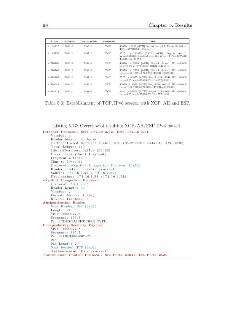
68 Chapter 5. Results
Time Source Destination Protocol Info
4.194127 2001::2 2002::1 TCP 43875 > 2525 [SYN] Seq=0 Len=0 MSS=1460 WS=1TSV=57740983 TSER=0
4.193755 2002::1 2001::2 TCP 2525 > 43875 [SYN, ACK] Seq=0 Ack=1Win=131070 Len=0 MSS=1460 WS=1 TSV=3425410TSER=57740983
4.213131 2001::2 2002::1 TCP 43875 > 2525 [ACK] Seq=1 Ack=1 Win=66608Len=0 TSV=57740988 TSER=3425410
4.216268 2001::2 2002::1 TCP 43875 > 2525 [ACK] Seq=1 Ack=1 Win=66608Len=1347 TSV=57740989 TSER=3425410
4.314285 2002::1 2001::2 TCP 2525 > 43875 [ACK] Seq=1 Ack=1348 Win=66608Len=0 TSV=3425516 TSER=57740989
4.315543 2001::2 2002::1 TCP 43875 > 2525 [ACK] Seq=1348 Ack=1 Win=66608Len=1347 TSV=57741094 TSER=3425516
4.414218 2002::1 2001::2 TCP 2525 > 43875 [ACK] Seq=1 Ack=2695 Win=66608Len=0 TSV=3425620 TSER=57741094
Table 5.6: Establishment of TCP/IPv6 session with XCP, AH and ESP.
Listing 5.17: Overview of resulting XCP/AH/ESP IPv4 packet.Internet Protocol , Src : 172.16.2.52 , Dst : 172.16.3.51
Vers ion : 4Header l ength : 20 bytesD i f f e r e n t i a t e d S e r v i c e s F i e ld : 0x00 (DSCP 0x00 : Defau l t ; ECN: 0x00 )Total Length : 160I d e n t i f i c a t i o n : 0 x f7ea (63466)Flags : 0x04 (Don ’ t Fragment )Fragment o f f s e t : 0Time to l i v e : 63Protoco l : eXp l i c i t Congest ion Protoco l (0 x72 )Header checksum : 0xe579 [ c o r r e c t ]Source : 1 7 2 . 1 6 . 2 . 5 2 ( 1 7 2 . 1 6 . 2 . 5 2 )Des t inat i on : 1 7 2 . 1 6 . 3 . 5 1 ( 1 7 2 . 1 6 . 3 . 5 1 )
eXplicit Congestion Protocol
Protoco l : AH (0 x33 )Header Length : 40Vers ion : 2Format : Minimal (0 x02 )Reverse Feedback : 0
Authentication Header
Next Header : ESP (0 x32 )Length : 24SPI : 0x00002708Sequence : 19547IV : 2CD7D29A1EE3503FC9FF8134
Encapsulating Security Payload
SPI : 0x00002708Sequence : 19547IV : 247BCE86926079F6PadPad Length : 2Next header : TCP (0 x06 )Authent icat ion Data [ c o r r e c t ]
Transmission Control Protocol , Src Port : 64641, Dst Port : 2525
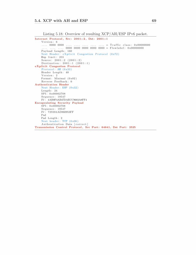
5.4. XCP with AH and ESP 69
Listing 5.18: Overview of resulting XCP/AH/ESP IPv6 packet.Internet Protocol , Src : 2001::2 , Dst : 2001::1
Vers ion : 6. . . . 0000 0000 . . . . . . . . . . . . . . . . . . . . = T r a f f i c c l a s s : 0x00000000. . . . . . . . . . . . 0000 0000 0000 0000 0000 = Flowlabe l : 0x00000000Payload Length : 160Next Header : eXp l i c i t Congest ion Protoco l (0 x72 )Hop l im i t : 255Source : 2 001 : : 2 ( 2 0 0 1 : : 2 )Des t inat i on : 2 001 : : 1 ( 2 0 0 1 : : 1 )
eXplicit Congestion Protocol
Protoco l : AH (0 x33 )Header Length : 40Vers ion : 2Format : Minimal (0 x02 )Reverse Feedback : 0
Authentication Header
Next Header : ESP (0 x32 )Length : 24SPI : 0x00002708Sequence : 19547IV : 4AB9F4AB47DAECC9683A8FF4
Encapsulating Security Payload
SPI : 0x00002708Sequence : 19547IV : 729384AD860953FFPadPad Length : 2Next header : TCP (0 x06 )Authent icat ion Data [ c o r r e c t ]
Transmission Control Protocol , Src Port : 64641, Dst Port : 2525
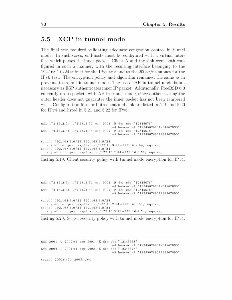
70 Chapter 5. Results
5.5 XCP in tunnel mode
The final test required validating adequate congestion control in tunnelmode. In such cases, end-hosts must be configured with a virtual inter-face which parses the inner packet. Client A and the sink were both con-figured in such a manner, with the resulting interface belonging to the192.168.1.0/24 subnet for the IPv4 test and to the 2003::/64 subnet for theIPv6 test. The encryption policy and algorithm remained the same as inprevious tests, but in tunnel mode. The use of AH in tunnel mode is un-necessary as ESP authenticates inner IP packet. Additionally, FreeBSD 6.0currently drops packets with AH in tunnel mode, since authenticating theouter header does not guarantee the inner packet has not been tamperedwith. Configuration files for both client and sink are listed in 5.19 and 5.20for IPv4 and listed in 5.21 and 5.22 for IPv6.
add 172 . 1 6 . 2 . 5 4 172 . 1 6 . 3 . 5 1 esp 9991 −E des−cbc ”12345678”−A hmac−sha1 ”12345678901234567890” ;
add 172 . 1 6 . 3 . 5 1 172 . 1 6 . 2 . 5 4 esp 9992 −E des−cbc ”12345678”−A hmac−sha1 ”12345678901234567890” ;
spdadd 192 . 168 . 1 . 0/24 192 . 168 . 1 . 0/24any −P in i p s e c esp / tunne l /172 .16 . 3 . 51 −172 .16 . 2 . 54/ r e qu i r e ;
spdadd 192 . 168 . 1 . 0/24 192 . 168 . 1 . 0/24any −P out i p s e c esp / tunne l /172 .16 . 2 . 54 −172 .16 . 3 . 51/ r e qu i r e ;
Listing 5.19: Client security policy with tunnel mode encryption for IPv4.
add 172 . 1 6 . 2 . 5 4 172 . 1 6 . 3 . 5 1 esp 9991 −E des−cbc ”12345678”−A hmac−sha1 ”12345678901234567890” ;
add 172 . 1 6 . 3 . 5 1 172 . 1 6 . 2 . 5 4 esp 9992 −E des−cbc ”12345678”−A hmac−sha1 ”12345678901234567890” ;
spdadd 192 . 168 . 1 . 0/24 192 . 168 . 1 . 0/24any −P in i p s e c esp / tunne l /172 .16 . 2 . 54 −172 .16 . 3 . 51/ r e qu i r e ;
spdadd 192 . 168 . 1 . 0/24 192 . 168 . 1 . 0/24any −P out i p s e c esp / tunne l /172 .16 . 3 . 51 −172 .16 . 2 . 54/ r e qu i r e ;
Listing 5.20: Server security policy with tunnel mode encryption for IPv4.
add 2001 : : 4 2002 : : 1 esp 9991 −E des−cbc ”12345678”−A hmac−sha1 ”12345678901234567890” ;
add 2002 : : 1 2001 : : 4 esp 9992 −E des−cbc ”12345678”−A hmac−sha1 ”12345678901234567890” ;
spdadd 2003 : : /64 2003 : : /64
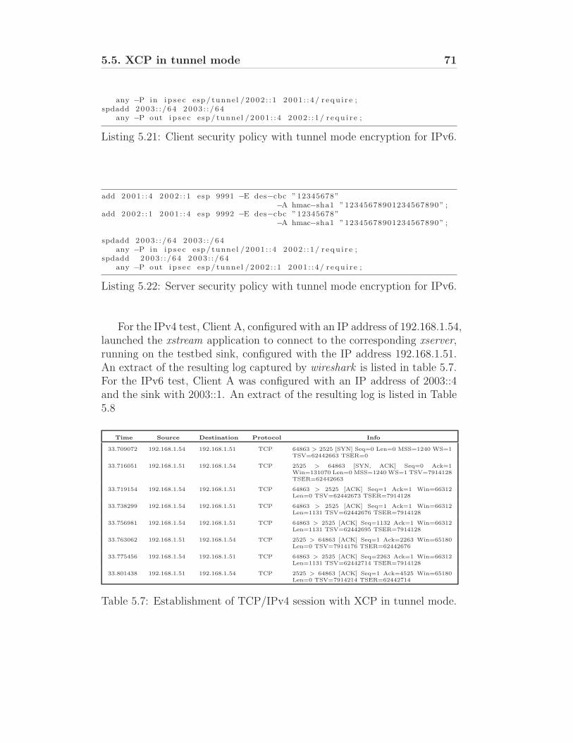
5.5. XCP in tunnel mode 71
any −P in i p s e c esp / tunne l /2002 : : 1 2001 : : 4 / r e qu i r e ;spdadd 2003 : : /64 2003 : : /64
any −P out i p s e c esp / tunne l /2001 : : 4 2002 : : 1 / r e qu i r e ;
Listing 5.21: Client security policy with tunnel mode encryption for IPv6.
add 2001 : : 4 2002 : : 1 esp 9991 −E des−cbc ”12345678”−A hmac−sha1 ”12345678901234567890” ;
add 2002 : : 1 2001 : : 4 esp 9992 −E des−cbc ”12345678”−A hmac−sha1 ”12345678901234567890” ;
spdadd 2003 : : /64 2003 : : /64any −P in i p s e c esp / tunne l /2001 : : 4 2002 : : 1 / r e qu i r e ;
spdadd 2003 : : /64 2003 : : /64any −P out i p s e c esp / tunne l /2002 : : 1 2001 : : 4 / r e qu i r e ;
Listing 5.22: Server security policy with tunnel mode encryption for IPv6.
For the IPv4 test, Client A, configured with an IP address of 192.168.1.54,launched the xstream application to connect to the corresponding xserver,running on the testbed sink, configured with the IP address 192.168.1.51.An extract of the resulting log captured by wireshark is listed in table 5.7.For the IPv6 test, Client A was configured with an IP address of 2003::4and the sink with 2003::1. An extract of the resulting log is listed in Table5.8
Time Source Destination Protocol Info
33.709072 192.168.1.54 192.168.1.51 TCP 64863 > 2525 [SYN] Seq=0 Len=0 MSS=1240 WS=1TSV=62442663 TSER=0
33.716051 192.168.1.51 192.168.1.54 TCP 2525 > 64863 [SYN, ACK] Seq=0 Ack=1Win=131070 Len=0 MSS=1240 WS=1 TSV=7914128TSER=62442663
33.719154 192.168.1.54 192.168.1.51 TCP 64863 > 2525 [ACK] Seq=1 Ack=1 Win=66312Len=0 TSV=62442673 TSER=7914128
33.738299 192.168.1.54 192.168.1.51 TCP 64863 > 2525 [ACK] Seq=1 Ack=1 Win=66312Len=1131 TSV=62442676 TSER=7914128
33.756981 192.168.1.54 192.168.1.51 TCP 64863 > 2525 [ACK] Seq=1132 Ack=1 Win=66312Len=1131 TSV=62442695 TSER=7914128
33.763062 192.168.1.51 192.168.1.54 TCP 2525 > 64863 [ACK] Seq=1 Ack=2263 Win=65180Len=0 TSV=7914176 TSER=62442676
33.775456 192.168.1.54 192.168.1.51 TCP 64863 > 2525 [ACK] Seq=2263 Ack=1 Win=66312Len=1131 TSV=62442714 TSER=7914128
33.801438 192.168.1.51 192.168.1.54 TCP 2525 > 64863 [ACK] Seq=1 Ack=4525 Win=65180Len=0 TSV=7914214 TSER=62442714
Table 5.7: Establishment of TCP/IPv4 session with XCP in tunnel mode.
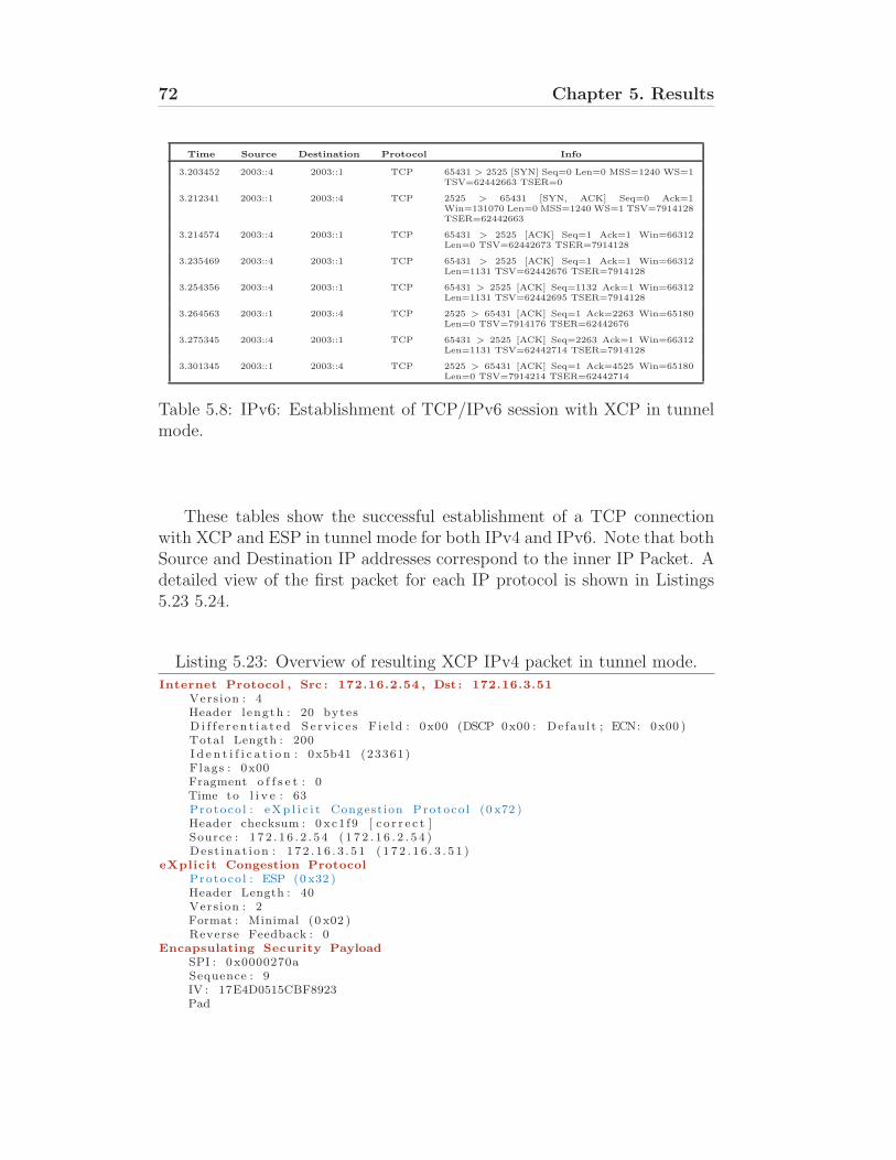
72 Chapter 5. Results
Time Source Destination Protocol Info
3.203452 2003::4 2003::1 TCP 65431 > 2525 [SYN] Seq=0 Len=0 MSS=1240 WS=1TSV=62442663 TSER=0
3.212341 2003::1 2003::4 TCP 2525 > 65431 [SYN, ACK] Seq=0 Ack=1Win=131070 Len=0 MSS=1240 WS=1 TSV=7914128TSER=62442663
3.214574 2003::4 2003::1 TCP 65431 > 2525 [ACK] Seq=1 Ack=1 Win=66312Len=0 TSV=62442673 TSER=7914128
3.235469 2003::4 2003::1 TCP 65431 > 2525 [ACK] Seq=1 Ack=1 Win=66312Len=1131 TSV=62442676 TSER=7914128
3.254356 2003::4 2003::1 TCP 65431 > 2525 [ACK] Seq=1132 Ack=1 Win=66312Len=1131 TSV=62442695 TSER=7914128
3.264563 2003::1 2003::4 TCP 2525 > 65431 [ACK] Seq=1 Ack=2263 Win=65180Len=0 TSV=7914176 TSER=62442676
3.275345 2003::4 2003::1 TCP 65431 > 2525 [ACK] Seq=2263 Ack=1 Win=66312Len=1131 TSV=62442714 TSER=7914128
3.301345 2003::1 2003::4 TCP 2525 > 65431 [ACK] Seq=1 Ack=4525 Win=65180Len=0 TSV=7914214 TSER=62442714
Table 5.8: IPv6: Establishment of TCP/IPv6 session with XCP in tunnelmode.
These tables show the successful establishment of a TCP connectionwith XCP and ESP in tunnel mode for both IPv4 and IPv6. Note that bothSource and Destination IP addresses correspond to the inner IP Packet. Adetailed view of the first packet for each IP protocol is shown in Listings5.23 5.24.
Listing 5.23: Overview of resulting XCP IPv4 packet in tunnel mode.Internet Protocol , Src : 172.16.2.54 , Dst : 172.16.3.51
Vers ion : 4Header l ength : 20 bytesD i f f e r e n t i a t e d S e r v i c e s F i e ld : 0x00 (DSCP 0x00 : Defau l t ; ECN: 0x00 )Total Length : 200I d e n t i f i c a t i o n : 0x5b41 (23361)Flags : 0x00Fragment o f f s e t : 0Time to l i v e : 63Protoco l : eXp l i c i t Congest ion Protoco l (0 x72 )Header checksum : 0 xc1 f9 [ c o r r e c t ]Source : 1 7 2 . 1 6 . 2 . 5 4 ( 1 7 2 . 1 6 . 2 . 5 4 )Des t inat i on : 1 7 2 . 1 6 . 3 . 5 1 ( 1 7 2 . 1 6 . 3 . 5 1 )
eXplicit Congestion Protocol
Protoco l : ESP (0 x32 )Header Length : 40Vers ion : 2Format : Minimal (0 x02 )Reverse Feedback : 0
Encapsulating Security Payload
SPI : 0x0000270aSequence : 9IV : 17E4D0515CBF8923Pad
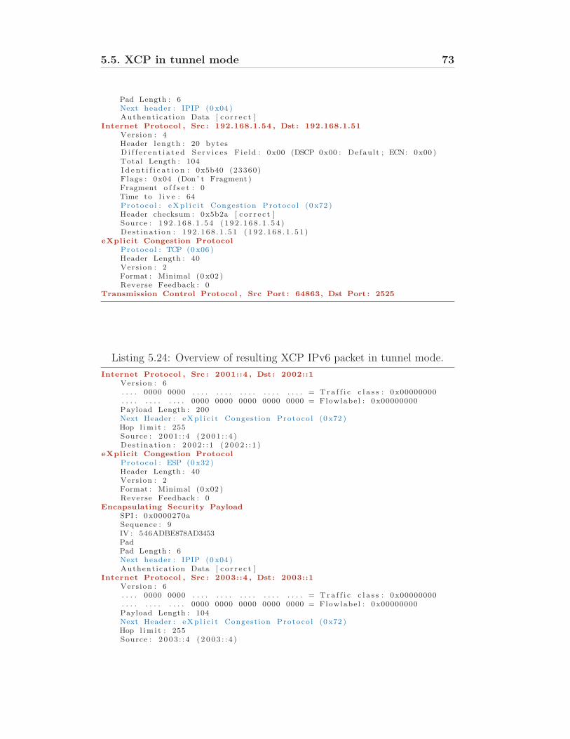
5.5. XCP in tunnel mode 73
Pad Length : 6Next header : IPIP (0 x04 )Authent icat ion Data [ c o r r e c t ]
Internet Protocol , Src : 192.168.1.54 , Dst : 192.168.1.51
Vers ion : 4Header l ength : 20 bytesD i f f e r e n t i a t e d S e r v i c e s F i e ld : 0x00 (DSCP 0x00 : Defau l t ; ECN: 0x00 )Total Length : 104I d e n t i f i c a t i o n : 0x5b40 (23360)Flags : 0x04 (Don ’ t Fragment )Fragment o f f s e t : 0Time to l i v e : 64Protoco l : eXp l i c i t Congest ion Protoco l (0 x72 )Header checksum : 0x5b2a [ c o r r e c t ]Source : 1 92 . 1 68 . 1 . 5 4 ( 1 9 2 . 1 6 8 . 1 . 5 4 )Des t inat i on : 1 92 . 1 68 . 1 . 5 1 ( 1 9 2 . 1 6 8 . 1 . 5 1 )
eXplicit Congestion Protocol
Protoco l : TCP (0 x06 )Header Length : 40Vers ion : 2Format : Minimal (0 x02 )Reverse Feedback : 0
Transmission Control Protocol , Src Port : 64863, Dst Port : 2525
Listing 5.24: Overview of resulting XCP IPv6 packet in tunnel mode.
Internet Protocol , Src : 2001::4 , Dst : 2002::1
Vers ion : 6. . . . 0000 0000 . . . . . . . . . . . . . . . . . . . . = T r a f f i c c l a s s : 0x00000000. . . . . . . . . . . . 0000 0000 0000 0000 0000 = Flowlabe l : 0x00000000Payload Length : 200Next Header : eXp l i c i t Congest ion Protoco l (0 x72 )Hop l im i t : 255Source : 2 001 : : 4 ( 2 0 0 1 : : 4 )Des t inat i on : 2 002 : : 1 ( 2 0 0 2 : : 1 )
eXplicit Congestion Protocol
Protoco l : ESP (0 x32 )Header Length : 40Vers ion : 2Format : Minimal (0 x02 )Reverse Feedback : 0
Encapsulating Security Payload
SPI : 0x0000270aSequence : 9IV : 546ADBE878AD3453PadPad Length : 6Next header : IPIP (0 x04 )Authent icat ion Data [ c o r r e c t ]
Internet Protocol , Src : 2003::4 , Dst : 2003::1
Vers ion : 6. . . . 0000 0000 . . . . . . . . . . . . . . . . . . . . = T r a f f i c c l a s s : 0x00000000. . . . . . . . . . . . 0000 0000 0000 0000 0000 = Flowlabe l : 0x00000000Payload Length : 104Next Header : eXp l i c i t Congest ion Protoco l (0 x72 )Hop l im i t : 255Source : 2 003 : : 4 ( 2 0 0 3 : : 4 )
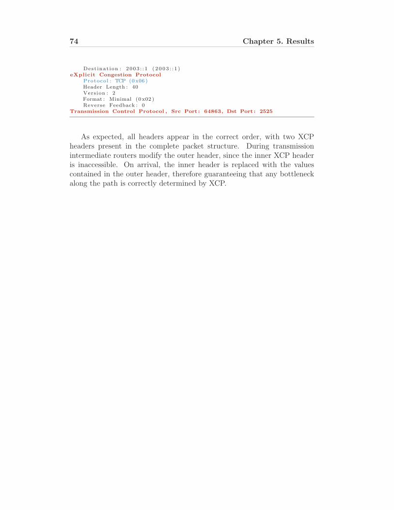
74 Chapter 5. Results
Dest inat i on : 2 003 : : 1 ( 2 0 0 3 : : 1 )eXplicit Congestion Protocol
Protoco l : TCP (0 x06 )Header Length : 40Vers ion : 2Format : Minimal (0 x02 )Reverse Feedback : 0
Transmission Control Protocol , Src Port : 64863, Dst Port : 2525
As expected, all headers appear in the correct order, with two XCPheaders present in the complete packet structure. During transmissionintermediate routers modify the outer header, since the inner XCP headeris inaccessible. On arrival, the inner header is replaced with the valuescontained in the outer header, therefore guaranteeing that any bottleneckalong the path is correctly determined by XCP.
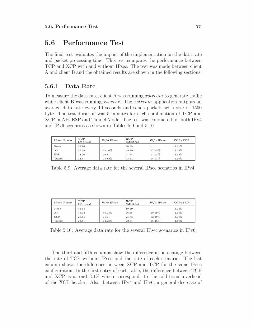
5.6. Performance Test 75
5.6 Performance Test
The final test evaluates the impact of the implementation on the data rateand packet processing time. This test compares the performance betweenTCP and XCP with and without IPsec. The test was made between clientA and client B and the obtained results are shown in the following sections.
5.6.1 Data Rate
To measure the data rate, client A was running xstream to generate trafficwhile client B was running xserver. The xstream application outputs anaverage data rate every 10 seconds and sends packets with size of 1500byte. The test duration was 5 minutes for each combination of TCP andXCP in AH, ESP and Tunnel Mode. The test was conducted for both IPv4and IPv6 scenarios as shown in Tables 5.9 and 5.10.
IPsec ProtoTCP(Mbit/s)
W/o IPsecXCP(Mbit/s)
W/o IPsec XCP/TCP
None 93.86 - 90.95 - -3.11%
AH 51.09 -45.56% 49.49 -47.75% -3.14%
ESP 28.06 -70.11 27.18 -71.04% -3.13%
Tunnel 24.57 -73.82% 23.43 -75.04% -4.66%
Table 5.9: Average data rate for the several IPsec scenarios in IPv4.
IPsec ProtoTCP(Mbit/s)
W/o IPsecXCP(Mbit/s)
W/o IPsec XCP/TCP
None 92.53 - 89.69 - -3.08%
AH 48.04 -48.08% 46.55 -49.69% -3.11%
ESP 26.55 -71.31 25.73 -72.19% -3.08%
Tunnel 23.8 -74.28% 22.71 -75.46% -4.58%
Table 5.10: Average data rate for the several IPsec scenarios in IPv6.
The third and fifth columns show the difference in percentage betweenthe rate of TCP without IPsec and the rate of each scenario. The lastcolumn shows the difference between XCP and TCP for the same IPsecconfiguration. In the first entry of each table, the difference between TCPand XCP is arrond 3.1% which corresponds to the additional overheadof the XCP header. Also, between IPv4 and IPv6, a general decrease of
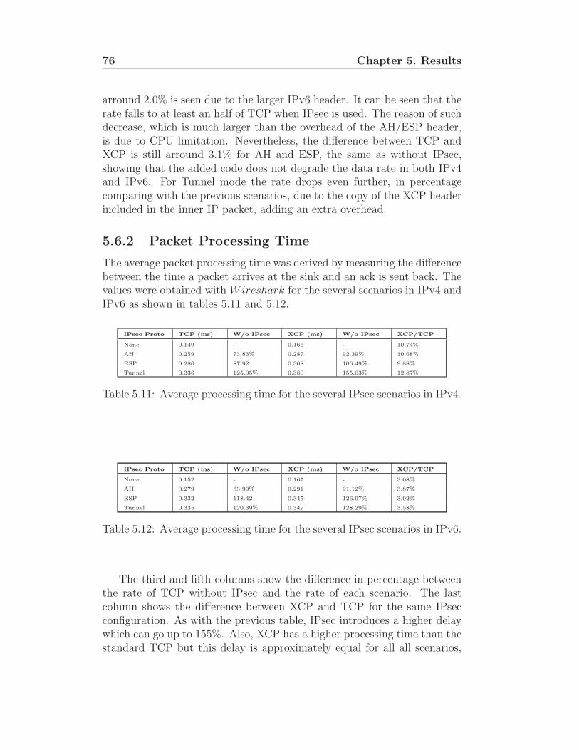
76 Chapter 5. Results
arround 2.0% is seen due to the larger IPv6 header. It can be seen that therate falls to at least an half of TCP when IPsec is used. The reason of suchdecrease, which is much larger than the overhead of the AH/ESP header,is due to CPU limitation. Nevertheless, the difference between TCP andXCP is still arround 3.1% for AH and ESP, the same as without IPsec,showing that the added code does not degrade the data rate in both IPv4and IPv6. For Tunnel mode the rate drops even further, in percentagecomparing with the previous scenarios, due to the copy of the XCP headerincluded in the inner IP packet, adding an extra overhead.
5.6.2 Packet Processing Time
The average packet processing time was derived by measuring the differencebetween the time a packet arrives at the sink and an ack is sent back. Thevalues were obtained with Wireshark for the several scenarios in IPv4 andIPv6 as shown in tables 5.11 and 5.12.
IPsec Proto TCP (ms) W/o IPsec XCP (ms) W/o IPsec XCP/TCP
None 0.149 - 0.165 - 10.74%
AH 0.259 73.83% 0.287 92.39% 10.68%
ESP 0.280 87.92 0.308 106.49% 9.88%
Tunnel 0.336 125.95% 0.380 155.03% 12.87%
Table 5.11: Average processing time for the several IPsec scenarios in IPv4.
IPsec Proto TCP (ms) W/o IPsec XCP (ms) W/o IPsec XCP/TCP
None 0.152 - 0.167 - 3.08%
AH 0.279 83.99% 0.291 91.12% 3.87%
ESP 0.332 118.42 0.345 126.97% 3.92%
Tunnel 0.335 120.39% 0.347 128.29% 3.58%
Table 5.12: Average processing time for the several IPsec scenarios in IPv6.
The third and fifth columns show the difference in percentage betweenthe rate of TCP without IPsec and the rate of each scenario. The lastcolumn shows the difference between XCP and TCP for the same IPsecconfiguration. As with the previous table, IPsec introduces a higher delaywhich can go up to 155%. Also, XCP has a higher processing time than thestandard TCP but this delay is approximately equal for all all scenarios,
5.6. Performance Test 77
so it can be inferred that the implementation has no visible impact on theprocessing time. It is also noticeable that IPv6 has considerable less delaythan IPv4 in all IPsec scenarios. This is due to the native support of IPsecin the IPv6 stack.

Chapter 6
Conclusion
In this final chapter conclusions are drawn on the proposed objectives andthe developed work that was made.
FreeBSD stack A great deal of effort went into learning the inner work-ings of the networking stack. Engineered towards performance first andforemost, understanding the kernel presents a challenge within itself. Thetypical FreeBSD scattered and sparsely documented also made the learningmore difficult.
Nevertheless, all the networking routines were pinpointed which allowedto derive the modifications to the kernel.
Explicit congestion control with network security The second taskwas to integrate explicit congestion protocols (e.g XCP) with IPsec, thesecurity framework responsible for providing data integrity and privacy atthe network layer, in IPv4 and IPv6. The proposed implementation correctsarchitectural fallacies in the networking stack which prevent routers fromproviding feedback for explicit congestion control protocols in the presenceof packet encryption or authentication. This approach was validated byestablishing secure end-to-end connections subject to congestion control bysuch protocols. Also, the performance test shown that the modificationshas a negligible impact on the data rate and packet processing time.
These modifications are relevant in allowing explicit congestion controlto be performed without compromising security and provide additionalprotection to immutable data fields associated to the congestion controlheader, an important benefit in a control system where end-host statisticsinfluence core network response.
Whilst the implementation successfully extended IPsec to become awareof an explicit congestion control protocol, protocol transparency requires
79
80 Chapter 6. Conclusion
that network layer security be decoupled from IP. With the emergence ofend-to-network protocols such as XCP and RCP, the borderline betweennetwork and transport layer may no longer be drawn at IP. By incorrectlyassuming that security must follow the IP header, IPsec constitutes anobstacle to any protocol wishing to operate both over IP and at the networklayer. In IPv6, these issues may be partially circumvented by implementingXCP as an IPv6 Extension header as was made on the proposed approach.
Appendix A
BSD License
Copyright (c) 2007-2008, INESC-PortoAll rights reserved.Redistribution and use in source and binary forms, with or without modification,
are permitted provided that the following conditions are met:Redistributions of source code must retain the above copyright notice, this list of
conditions and the following disclaimer. Redistributions in binary form must reproducethe above copyright notice, this list of conditions and the following disclaimer in thedocumentation and/or other materials provided with the distribution. Neither the nameof the INESC-Porto nor the names of its contributors may be used to endorse or promoteproducts derived from this software without specific prior written permission.
THIS SOFTWARE IS PROVIDED BY THE COPYRIGHT HOLDERS AND CON-TRIBUTORS ”AS IS” AND ANY EXPRESS OR IMPLIED WARRANTIES, INCLUD-ING, BUT NOT LIMITED TO, THE IMPLIED WARRANTIES OF MERCHANTABIL-ITY AND FITNESS FOR A PARTICULAR PURPOSE ARE DISCLAIMED. IN NOEVENT SHALL THE COPYRIGHT OWNER OR CONTRIBUTORS BE LIABLEFOR ANY DIRECT, INDIRECT, INCIDENTAL, SPECIAL, EXEMPLARY, OR CON-SEQUENTIAL DAMAGES (INCLUDING, BUT NOT LIMITED TO, PROCURE-MENT OF SUBSTITUTE GOODS OR SERVICES; LOSS OF USE, DATA, OR PROF-ITS; OR BUSINESS INTERRUPTION) HOWEVER CAUSED AND ON ANY THE-ORY OF LIABILITY, WHETHER IN CONTRACT, STRICT LIABILITY, OR TORT(INCLUDING NEGLIGENCE OR OTHERWISE) ARISING IN ANY WAY OUT OFTHE USE OF THIS SOFTWARE, EVEN IF ADVISED OF THE POSSIBILITY OFSUCH DAMAGE.
81

Bibliography
[1] I. S. Institute, “Transmission Control Protocol - Darpa Internet Program ProtocolSpecification.” RFC 793, September 1981.
[2] V. Jacobson and M. Karels, “Congestion Avoidance and Control,” tech. rep., ACMComputer Communication Review, August 1988.
[3] A. Falk, D. Katabi, and Y. Pryadkin, “Specification for the Explicit Control Pro-tocol (XCP) - draft-falk-xcp-02.” Internet-Draft, November 2006.
[4] N. Dukkipati and N. McKeown, “Processor Sharing Flows in the Internet,” Tech.Rep. TR04-HPNG-061604, Stanford University, June 2004.
[5] R. Atkinson, “Security Architecture for the Internet Protocol.” RFC 1825, August1995.
[6] S. Kent and K. Seo, “Security Architecture for the Internet Protocol.” RFC 4301,December 2005.
[7] S. Kent, “IP Authentication Headeri.” RFC 4302, Decemmber 2005.
[8] S. Kent, “IP Encapsulating Security Payload (ESP).” RFC 4303, Decemmber 2005.
[9] C. Madson and N. Doraswamy, “The ESP DES-CBC Cipher Algorithm With Ex-plicit IV.” RFC 2405, November 1998.
[10] R. Pereira and R. Adams, “The ESP CBC-Mode Cipher Algorithms.” RFC 2451,November 1998.
[11] R. Housley, “Using Advanced Encryption Standard (AES) CCM Mode with IPsecEncapsulating Security Payload (ESP).” RFC 4309, December 2005.
[12] C. Madson and R. Glenn, “The Use of HMAC-MD5-96 within ESP and AH.” RFC2403, November 1998.
[13] C. Madson and R. Glenn, “The Use of HMAC-SHA-1-96 within ESP and AH.”RFC 2404, November 1998.
[14] D. Clark, “Window and Acknowledgement Strategy in TCP.” RFC 813, July 1982.
[15] “About FreeBSD’s Internetworking.” http://www.freebsd.org/internet.html.
[16] “Nearly 2.5 Million Active Sites running FreeBSD.”http://news.netcraft.com/archives/2004/06/07/sitesrunningfreebsd.html.
[17] Michael O’Brien, “SunExpert,” August 1996.
[18] “Wireshark - Network Protocol Analyzer.” http://www.wireshark.org/.
83