Embed Size (px)
Citation preview
www.marshbellofram.com • 800.727.5646 57
Tran
sducers
I/P, E/P & P/I Transducers
Type 1000
Type 1000EX
Type 1000HR
Type 1000 Hazardous Use
Type 1001
Type 1001 Nema 3R
Type 1001 Nema 4X
Type 1500
Type 1500 Zero Based
Type 2000
Type 2000 Hazardous Use
Type 5000
58 800.727.5646 • www.marshbellofram.com
Tran
sducers
Description
The Type 1000 Transducer is an electro-pneu-matic device that reduces a supply pressure to a regulated output pressure directly proportional to an electrical input signal. The Type 1000 accepts a wide range of supply pressures, ranging from a minimum of 3 psig (0.2 BAR) above the maximum output up to 100 psig (6.9 BAR). An integral pneumatic volume booster is included in the design to provide high flow capacity (up to 12 sCFM/339 slpM). Model selections include general purpose, NEMA 4X Type, extended range, high relief, intrinsically safe, and explosion proof.
Applications
The Type 1000 Transducer converts an electri-cal signal to a pneumatic output which can be used to operate the following:
Valve actuatorsDamper and louver actuatorsValve positionersControllersRelaysAir cylindersClutches and brakes
Used in:
liquid, gas and slurry processing instrumen-tationHVAC systemspaper handling controlsTextile processing systemsEnergy management systemspetrochemical processing systems
Standard Features
low CostBuilt-in Volume Boostersmall sizeField Reversiblelow Air ConsumptionMounts at Any AngleConvenient External span & Zero Adjusts (Except for Explosion proof Models)light WeightWide supply pressure Rangelow supply pressure sensitivity
•••••••
•
•••••
•••••••
•••
Type 1000 I/P & E/P Transducers
Principle of Operation
The Type 1000 Transducer is a force balance device in which a coil is suspended in the field of a magnet by a flexure. Current flowing through the coil generates axial movement of the coil and flexure. The flexure moves against the end of a nozzle, and creates a back pressure in the nozzle by restricting air flow through it. This back pressure acts as a pilot pressure to an integral booster relay. Consequently, as the input signal increases (or decreases, for reverse acting), output pressure increases proportional-ly. Zero and span are calibrated by turning eas-ily accessible adjusting screws on the front face of the unit. The zero adjusting screw causes the nozzle to move relative to the flexure. The span adjusting screw is a potentiometer that limits the current through the coil. A thermistor circuit in series with the coil provides temperature compensation.
Split Ranging
The 4-20 mA input, 3-15 psig output model can be recalibrated to provide 3-9 psig or 9-15 psig output, for split ranging applications.
Mounting
The Type 1000 transducers can be pipe, panel, or bracket mounted in any position. positions other than vertical will require recalibration of the zero adjustment. For maximum output pressure stability, the Type 1000 should be mounted in a vibration-free location or such that vibration is isolated to the X and Z axis shown on the dimensional drawings.
Field Reversible
All Type 1000 transducers are calibrated at the factory for direct acting operation but may be used in the reverse acting mode by reversing the polarity of the signal leads and recalibrat-ing. When calibrated for reverse acting applica-tions, the Type 1000 transducers provide a minimum of their full rated output pressure (i.e., 15, 27, or 30 psig) upon input signal failure.
Type 1000 for Extended Range
Description
The Bellofram Extended Range i/p and E/p Transducers are based on Bellofram’s proven Type 1000 transducer line - the best selling transducers in the business.
The large span adjustment range of this line allows recalibration to fit applications with output ranges from approximately 3-35 psig (0.2-2.4 BAR) to 3-145 psig (0.2-10 BAR).
Type 1000 Transducers
The units accept supply pressures up to 150 psig (10.5 BAR) and provide flow capacity to 24 sCFM (677 slpM).
The Type 1000 i/p and E/p Transducers are more cost effective and more accurate than typical high output systems using transducers coupled to boosting or multiplying relays.
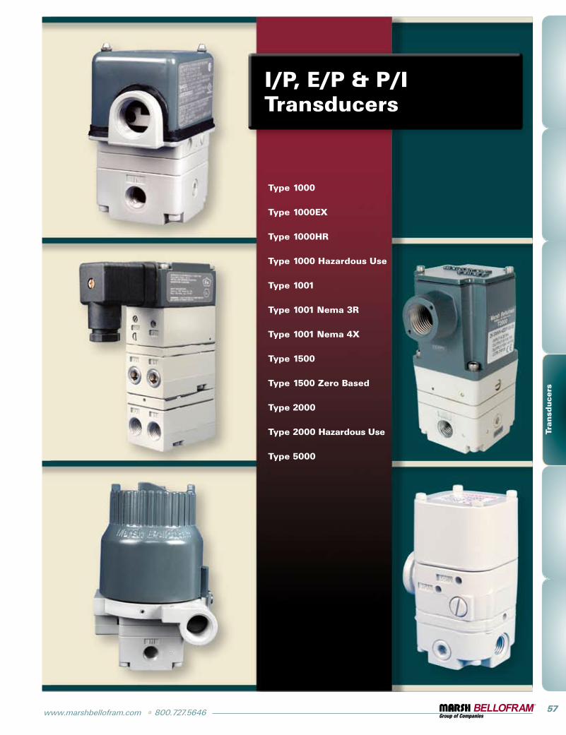
Type 1000 with High Relief
Description
Expanding upon the proven accuracy, reliabil-ity, and rugged construction of the Type 1000 general purpose, these transducers provide extra fast “blowdown” for a very rapid release of downstream pressure. The extra relief feature makes these units suitable for cylinder return stroke actuation, air hoists, and similar applica-tions requiring fast exhaust. These units accept supply pressures to 100 psig (6.9 BAR), with output ranges from 1-17 psig (0.07-1.2 BAR) to 6-30 psig (0.4-2.1 BAR), and provide exhaust capacities of 7 sCFM (336 slpM).
www.marshbellofram.com • 800.727.5646 59
Tran
sducers
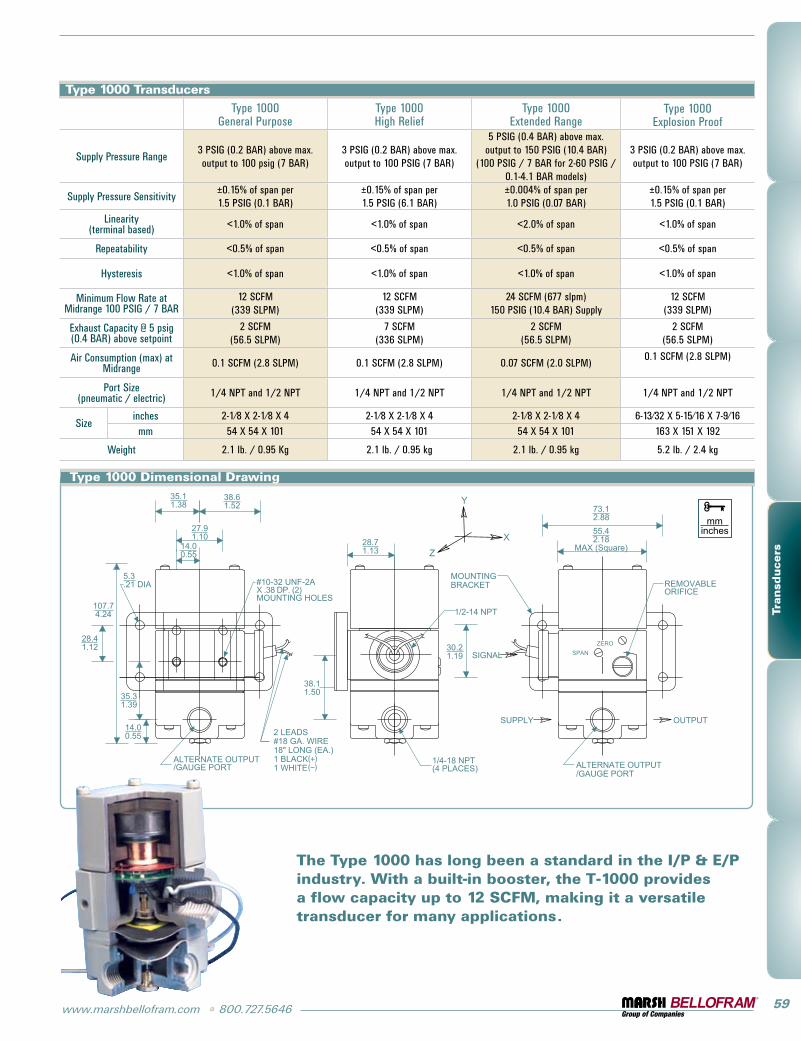
Type 1000 TransducersType 1000
general purposeType 1000High Relief
Type 1000Extended Range
Type 1000Explosion proof
supply pressure Range3 psig (0.2 BAR) above max. output to 100 psig (7 BAR)
3 psig (0.2 BAR) above max. output to 100 psig (7 BAR)
5 psig (0.4 BAR) above max. output to 150 psig (10.4 BAR)
(100 psig / 7 BAR for 2-60 psig / 0.1-4.1 BAR models)
3 psig (0.2 BAR) above max. output to 100 psig (7 BAR)
supply pressure sensitivity±0.15% of span per1.5 psig (0.1 BAR)
±0.15% of span per1.5 psig (6.1 BAR)
±0.004% of span per1.0 psig (0.07 BAR)
±0.15% of span per1.5 psig (0.1 BAR)
linearity (terminal based) <1.0% of span <1.0% of span <2.0% of span <1.0% of span
Repeatability <0.5% of span <0.5% of span <0.5% of span <0.5% of span
Hysteresis <1.0% of span <1.0% of span <1.0% of span <1.0% of span
Minimum Flow Rate at Midrange 100 psig / 7 BAR
12 sCFM(339 slpM)
12 sCFM(339 slpM)
24 sCFM (677 slpm)150 psig (10.4 BAR) supply
12 sCFM(339 slpM)
Exhaust Capacity @ 5 psig (0.4 BAR) above setpoint
2 sCFM(56.5 slpM)
7 sCFM(336 slpM)
2 sCFM(56.5 slpM)
2 sCFM(56.5 slpM)
Air Consumption (max) at Midrange 0.1 sCFM (2.8 slpM) 0.1 sCFM (2.8 slpM) 0.07 sCFM (2.0 slpM)
0.1 sCFM (2.8 slpM)
port size(pneumatic / electric) 1/4 NpT and 1/2 NpT 1/4 NpT and 1/2 NpT 1/4 NpT and 1/2 NpT 1/4 NpT and 1/2 NpT
size inches 2-1⁄8 X 2-1⁄8 X 4 2-1⁄8 X 2-1⁄8 X 4 2-1⁄8 X 2-1⁄8 X 4 6-13⁄32 X 5-15⁄16 X 7-9⁄16mm 54 X 54 X 101 54 X 54 X 101 54 X 54 X 101 163 X 151 X 192
Weight 2.1 lb. / 0.95 Kg 2.1 lb. / 0.95 kg 2.1 lb. / 0.95 kg 5.2 lb. / 2.4 kg
Type 1000 Dimensional Drawing
The Type 1000 has long been a standard in the I/P & E/P industry. With a built-in booster, the T-1000 provides a flow capacity up to 12 SCFM, making it a versatile transducer for many applications.
60 800.727.5646 • www.marshbellofram.com
Tran
sducers
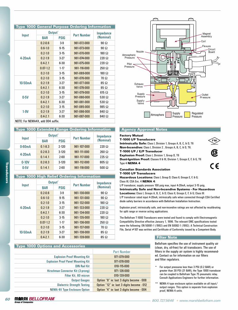
Type 1000 General Purpose Ordering Information
inputOutput*
part Number impedance(Nominal)BAR psig
4-20mA
0.2-0.6 3-9 961-072-000 90 Ω
0.6-1.0 9-15 961-073-000 90 Ω
0.2-1.0 3-15 961-070-000 180 Ω0.2-1.9 3-27 961-074-000 220 Ω0.4-2.1 6-30 961-075-000 220 Ω
0.07-1.2 1-17 961-116-000 250 Ω
0.2-1.0 3-15 961-089-000 180 Ω
10-50mA0.2-1.0 3-15 961-076-000 70 Ω0.2-1.9 3-27 961-077-000 85 Ω0.4-2.1 6-30 961-078-000 85 Ω
0-5V0.2-1.0 3-15 961-079-000 615 Ω0.2-1.9 3-27 961-080-000 530 Ω0.4-2.1 6-30 961-081-000 530 Ω
1-9V0.2-1.0 3-15 961-085-000 985 Ω0.2-1.9 3-27 961-086-000 840 Ω0.4-2.1 6-30 961-087-000 840 Ω
NOTE: For NEMA4X, add 004 suffix.
Type 1000 Extended Range Ordering Information
inputOutput*
part Number impedance(Nominal)BAR psig
0-60mA 0.1-8.3 2-120 961-107-000 220 Ω
4-20mA0.2-8.3 3-120 961-111-000 260 Ω
0.1-4.1 2-60 961-117-000 225 Ω
0-10V 0.2-8.3 3-120 961-112-000 805 Ω
0-5V 0.1-4.1 2-60 961-118-000 500 Ω
Type 1000 High Relief Ordering Information
inputOutput*
part Number impedance(Nominal)BAR psig
4-20mA
0.2-0.6 3-9 961-130-000 90 Ω0.6-1.0 9-15 961-131-000 90 Ω0.2-1.0 3-15 961-132-000 180 Ω0.2-1.9 3-27 961-133-000 220 Ω0.4-2.1 6-30 961-134-000 220 Ω0.2-1.0 3-15 961-135-000 180 Ω0.07-1.2 1-17 961-136-000 250 Ω
10-50mA0.2-1.0 3-15 961-137-000 70 Ω0.2-1.9 3-27 961-138-000 85 Ω0.4-2.1 6-30 961-139-000 85 Ω
Type 1000 Options and Accessories
part NumberExplosion proof Mounting Kit 971-079-000
Explosion proof panel Mounting Kit 971-078-000DiN Rail Kit 010-115-000
Hirschman Connector Kit (3-prong) 971-126-000Filter Kit, 60 micron 010-139-000
Output gauges Option “8” ie: last 3 digits become - 008Dielectric strength Testing Option “12” ie: last 3 digits become - 012
NEMA 4X Type Enclosure Option Option “4” ie: last 3 digits become - 004
* For output pressures less than 3 psi (0.2 BAR) or greater than 30 psi (21 BAR), the Type 1000 transducer can be coupled to Bellofram Type 75 pneumatic relay. Consult Applications Engineers for further information.
** NEMA 4 type enclosure option available on all input/output ranges. This option is separate from explosion proof, NEMA 4 units.
OutletPr essure
FlexureCircui tBoard
Coi l
MagnetAssembly
NozzleAtmospheric
Pressure
PilotPressure
ExhaustValve
SupplyPressure
Suppl yValve
Atmosphere SupplyPressure
RegulatedPressure
Agency Approval Notes
Filter Note
Bellofram specifies the use of instrument quality air (clean, dry, oil-free) for all transducers. The use of filters in the supply air system is highly recommend-ed. Contact us for information on our filters and filter regulators.
Factory Mutual T-1000 I/P Transducers Intrinsically Safe: Class i, Division 1, groups A, B, C, & D, T6 Non-Incendive: Class i, Division 2 , groups A, B, C, & D, T6. T-1000 I/P / E/P Transducer Explosion Proof: Class i, Division 1, group D, T6 Dust-Ignition Proof: Classes ii & iii, Division 1, groups E, F, & g, T6 Type 4 NEMA 4
Canadian Standards Association T-1000 I/P Transducers Hazardous Locations: Class i, group D; Class ii, groups E, F, & g; Class iii; CsA Enc. 4 NEMA 4: i/p transducer, supply pressure 100 psig max, input 4-20mA, output 3-15 psig. Intrinsically Safe and Non-Incendive Systems - For Hazardous Locations: Class i, groups A, B, C, & D; Class ii, groups E, F, & g; Class iii: i/p transducer rated input 4-20mA, intrinsically safe when connected through CsA Certified diode safety barriers in accordance with Bellofram installation instruction.
Explosion proof, intrinsically safe, and non-incendive ratings are not affected by recalibrating for split range or reverse acting applications.
The Bellofram T-1000 Transducers were tested and found to comply with Electromagnetic Compatibility Directive effective January 1, 1996. The relevant EMC specifications tested were the following: EN 50081-1 (1992) and EN 50082-1 (1992). A Technical Construction File, serial #107 was written and Certificate of Conformity issued by a Competent Body.
www.marshbellofram.com • 800.727.5646 61
Tran
sducers
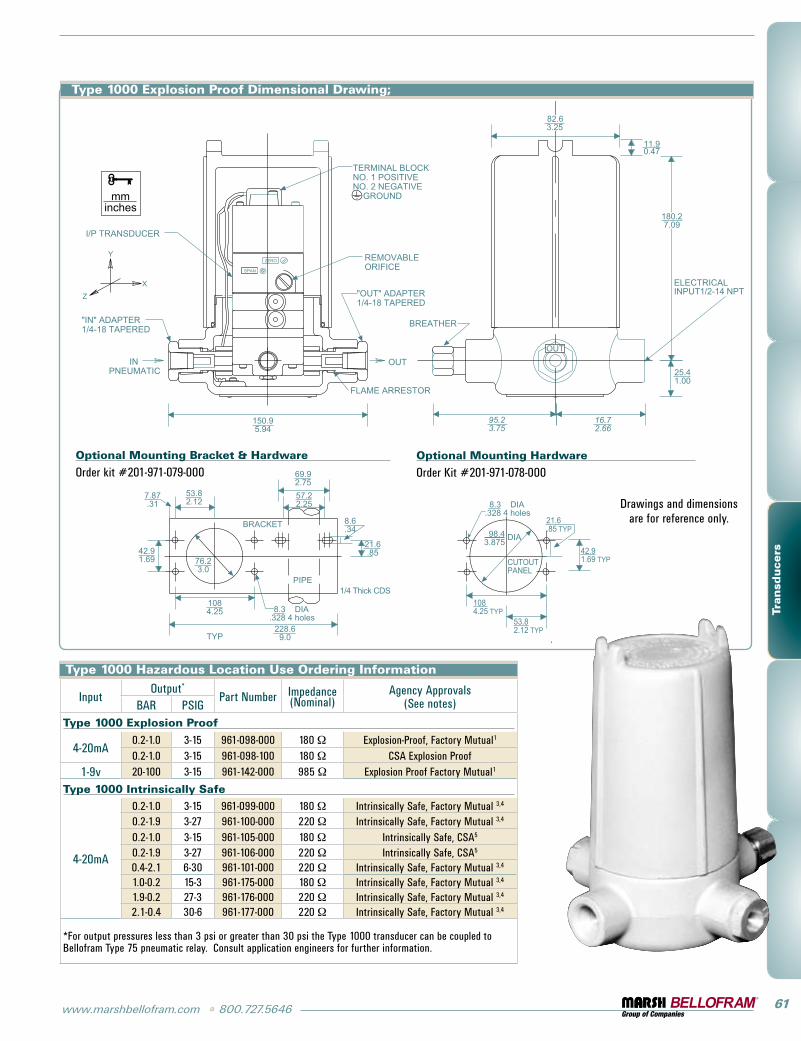
Type 1000 Explosion Proof Dimensional Drawing;
Optional Mounting Bracket & Hardware
Order kit #201-971-079-000Optional Mounting Hardware
Order Kit #201-971-078-000
Drawings and dimensions are for reference only.
Type 1000 Hazardous Location Use Ordering Information
inputOutput*
part Number impedance(Nominal)
Agency Approvals(see notes)BAR psig
Type 1000 Explosion Proof
4-20mA0.2-1.0 3-15 961-098-000 180 Ω Explosion-proof, Factory Mutual1
0.2-1.0 3-15 961-098-100 180 Ω CsA Explosion proof1-9v 20-100 3-15 961-142-000 985 Ω Explosion proof Factory Mutual1
Type 1000 Intrinsically Safe
4-20mA
0.2-1.0 3-15 961-099-000 180 Ω intrinsically safe, Factory Mutual 3,4
0.2-1.9 3-27 961-100-000 220 Ω intrinsically safe, Factory Mutual 3,4
0.2-1.0 3-15 961-105-000 180 Ω intrinsically safe, CsA5
0.2-1.9 3-27 961-106-000 220 Ω intrinsically safe, CsA5
0.4-2.1 6-30 961-101-000 220 Ω intrinsically safe, Factory Mutual 3,4
1.0-0.2 15-3 961-175-000 180 Ω intrinsically safe, Factory Mutual 3,4
1.9-0.2 27-3 961-176-000 220 Ω intrinsically safe, Factory Mutual 3,4
2.1-0.4 30-6 961-177-000 220 Ω intrinsically safe, Factory Mutual 3,4
*For output pressures less than 3 psi or greater than 30 psi the Type 1000 transducer can be coupled to Bellofram Type 75 pneumatic relay. Consult application engineers for further information.
62 800.727.5646 • www.marshbellofram.com
Tran
sducers
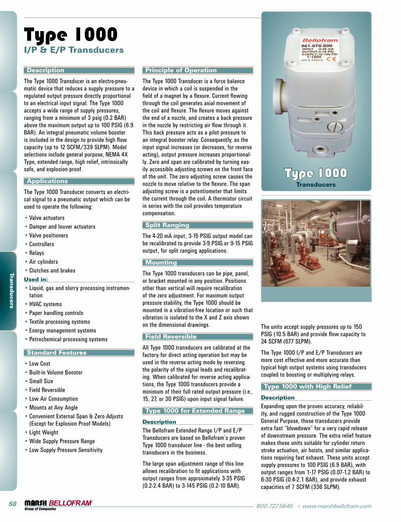
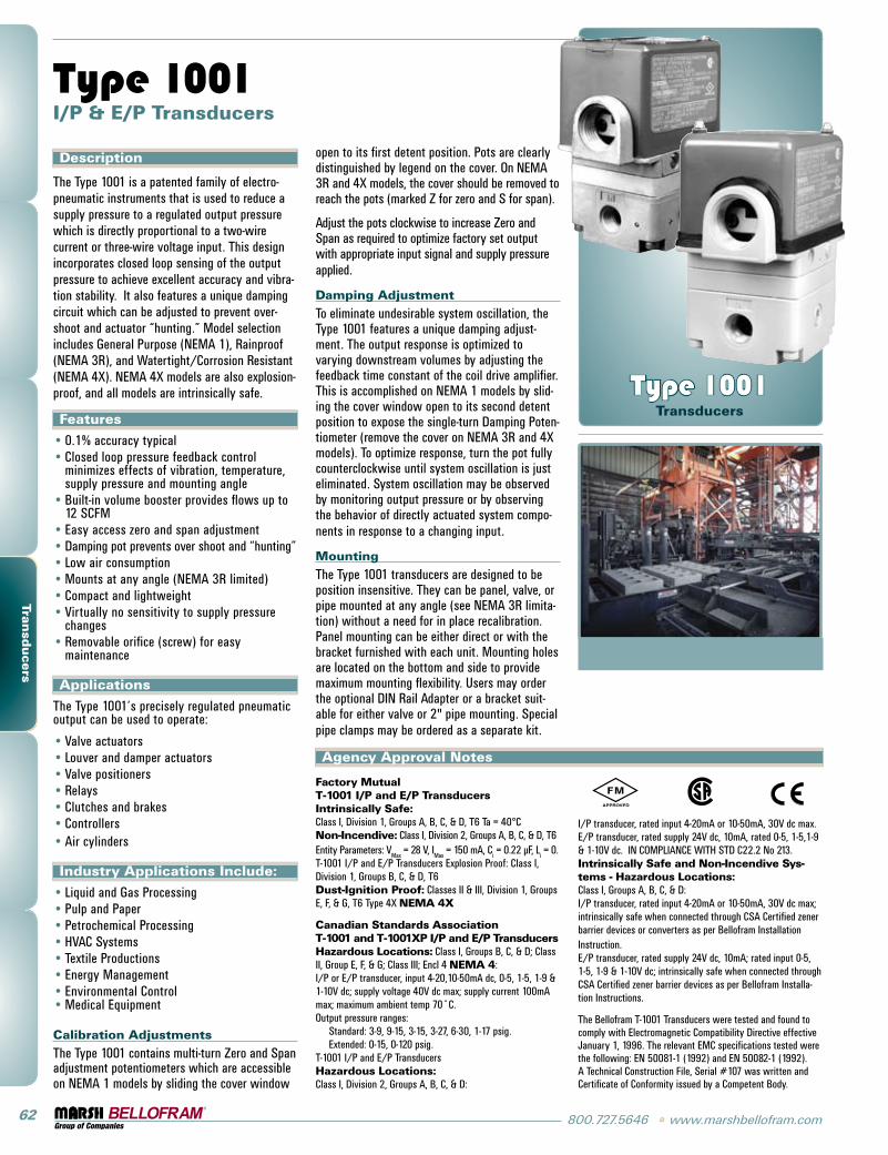
Description
The Type 1001 is a patented family of electro-pneumatic instruments that is used to reduce a supply pressure to a regulated output pressure which is directly proportional to a two-wire current or three-wire voltage input. This design incorporates closed loop sensing of the output pressure to achieve excellent accuracy and vibra-tion stability. it also features a unique damping circuit which can be adjusted to prevent over-shoot and actuator “hunting.” Model selection includes general purpose (NEMA 1), Rainproof (NEMA 3R), and Watertight/Corrosion Resistant (NEMA 4X). NEMA 4X models are also explosion-proof, and all models are intrinsically safe.
Features
0.1% accuracy typicalClosed loop pressure feedback control minimizes effects of vibration, temperature, supply pressure and mounting angleBuilt-in volume booster provides flows up to 12 sCFMEasy access zero and span adjustmentDamping pot prevents over shoot and “hunting”low air consumptionMounts at any angle (NEMA 3R limited)Compact and lightweightVirtually no sensitivity to supply pressure changesRemovable orifice (screw) for easy maintenance
Applications
The Type 1001’s precisely regulated pneumatic output can be used to operate:
Valve actuatorslouver and damper actuatorsValve positionersRelaysClutches and brakesControllersAir cylinders
Industry Applications Include:
liquid and gas processingpulp and paperpetrochemical processingHVAC systemsTextile productionsEnergy ManagementEnvironmental ControlMedical Equipment
Calibration Adjustments
The Type 1001 contains multi-turn Zero and span adjustment potentiometers which are accessible on NEMA 1 models by sliding the cover window
••
•
••••••
•
•••••••
••••••••
Type 1001 I/P & E/P Transducers
open to its first detent position. pots are clearly distinguished by legend on the cover. On NEMA 3R and 4X models, the cover should be removed to reach the pots (marked Z for zero and s for span).
Adjust the pots clockwise to increase Zero and span as required to optimize factory set output with appropriate input signal and supply pressure applied.
Damping Adjustment
To eliminate undesirable system oscillation, the Type 1001 features a unique damping adjust-ment. The output response is optimized to varying downstream volumes by adjusting the feedback time constant of the coil drive amplifier. This is accomplished on NEMA 1 models by slid-ing the cover window open to its second detent position to expose the single-turn Damping poten-tiometer (remove the cover on NEMA 3R and 4X models). To optimize response, turn the pot fully counterclockwise until system oscillation is just eliminated. system oscillation may be observed by monitoring output pressure or by observing the behavior of directly actuated system compo-nents in response to a changing input.
Mounting
The Type 1001 transducers are designed to be position insensitive. They can be panel, valve, or pipe mounted at any angle (see NEMA 3R limita-tion) without a need for in place recalibration. panel mounting can be either direct or with the bracket furnished with each unit. Mounting holes are located on the bottom and side to provide maximum mounting flexibility. Users may order the optional DiN Rail Adapter or a bracket suit-able for either valve or 2" pipe mounting. special pipe clamps may be ordered as a separate kit.
Type 1001 Transducers
Factory Mutual T-1001 I/P and E/P Transducers Intrinsically Safe: Class i, Division 1, groups A, B, C, & D, T6 Ta = 40°C Non-Incendive: Class i, Division 2, groups A, B, C, & D, T6 Entity parameters: V
Max = 28 V, i
Max = 150 mA, C
i = 0.22 μF, l
i = 0.
T-1001 i/p and E/p Transducers Explosion proof: Class i, Division 1, groups B, C, & D, T6 Dust-Ignition Proof: Classes ii & iii, Division 1, groups E, F, & g, T6 Type 4X NEMA 4X
Canadian Standards Association T-1001 and T-1001XP I/P and E/P Transducers Hazardous Locations: Class i, groups B, C, & D; Class ii, group E, F, & g; Class iii; Encl 4 NEMA 4: i/p or E/p transducer, input 4-20,10-50mA dc, 0-5, 1-5, 1-9 & 1-10V dc; supply voltage 40V dc max; supply current 100mA max; maximum ambient temp 70˚C. Output pressure ranges: standard: 3-9, 9-15, 3-15, 3-27, 6-30, 1-17 psig. Extended: 0-15, 0-120 psig. T-1001 i/p and E/p Transducers Hazardous Locations: Class i, Division 2, groups A, B, C, & D:
Agency Approval Notes
i/p transducer, rated input 4-20mA or 10-50mA, 30V dc max. E/p transducer, rated supply 24V dc, 10mA, rated 0-5, 1-5,1-9 & 1-10V dc. iN COMpliANCE WiTH sTD C22.2 No 213. Intrinsically Safe and Non-Incendive Sys-tems - Hazardous Locations: Class i, groups A, B, C, & D: i/p transducer, rated input 4-20mA or 10-50mA, 30V dc max; intrinsically safe when connected through CsA Certified zener barrier devices or converters as per Bellofram installation instruction. E/p transducer, rated supply 24V dc, 10mA; rated input 0-5, 1-5, 1-9 & 1-10V dc; intrinsically safe when connected through CsA Certified zener barrier devices as per Bellofram installa-tion instructions.
The Bellofram T-1001 Transducers were tested and found to comply with Electromagnetic Compatibility Directive effective January 1, 1996. The relevant EMC specifications tested were the following: EN 50081-1 (1992) and EN 50082-1 (1992). A Technical Construction File, serial #107 was written and Certificate of Conformity issued by a Competent Body.
www.marshbellofram.com • 800.727.5646 63
Tran
sducers
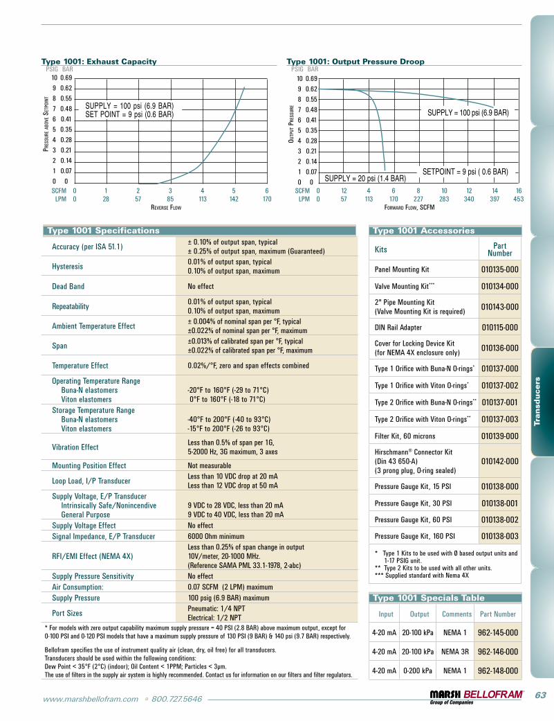
Type 1001: Exhaust Capacity
10 0.69
9 0.62
8 0.55
7 0.48
6 0.41
5 0.35
4 0.28
3 0.21
2 0.14
1 0.07
0 0 sCFM 0 1 2 3 4 5 6 lpM 0 28 57 85 113 142 170 ReveRse Flow
psig BAR
PRes
suRe
abo
ve s
etPo
int
Type 1001: Output Pressure Droop
10 0.69
9 0.62
8 0.55
7 0.48
6 0.41
5 0.35
4 0.28
3 0.21
2 0.14
1 0.07
0 0 sCFM 0 12 4 6 8 10 12 14 16 lpM 0 57 113 170 227 283 340 397 453
FoRwaRd Flow, sCFM
psig BAR
outP
ut P
Ress
uRe
Type 1001 Specifications
Accuracy (per isA 51.1) ± 0.10% of output span, typical± 0.25% of output span, maximum (guaranteed)
Hysteresis 0.01% of output span, typical 0.10% of output span, maximum
Dead Band No effect
Repeatability 0.01% of output span, typical 0.10% of output span, maximum
Ambient Temperature Effect ± 0.004% of nominal span per °F, typical ±0.022% of nominal span per °F, maximum
span ±0.013% of calibrated span per °F, typical ±0.022% of calibrated span per °F, maximum
Temperature Effect 0.02%/°F, zero and span effects combined
Operating Temperature Range Buna-N elastomers Viton elastomers
-20°F to 160°F (-29 to 71°C) 0°F to 160°F (-18 to 71°C)
storage Temperature Range Buna-N elastomers Viton elastomers
-40°F to 200°F (-40 to 93°C) -15°F to 200°F (-26 to 93°C)
Vibration Effect less than 0.5% of span per 1g, 5-2000 Hz, 3g maximum, 3 axes
Mounting position Effect Not measurable
loop load, i/p Transducer less than 10 VDC drop at 20 mA less than 12 VDC drop at 50 mA
supply Voltage, E/p Transducer intrinsically safe/Nonincendive general purpose
9 VDC to 28 VDC, less than 20 mA 9 VDC to 40 VDC, less than 20 mA
supply Voltage Effect No effectsignal impedance, E/p Transducer 6000 Ohm minimum
RFi/EMi Effect (NEMA 4X)less than 0.25% of span change in output 10V/meter, 20-1000 MHz. (Reference sAMA pMl 33.1-1978, 2-abc)
supply pressure sensitivity No effectAir Consumption: 0.07 sCFM (2 lpM) maximumsupply pressure 100 psig (6.9 BAR) maximum
port sizes pneumatic: 1/4 NpT Electrical: 1/2 NpT
* For models with zero output capability maximum supply pressure = 40 psi (2.8 BAR) above maximum output, except for 0-100 psi and 0-120 psi models that have a maximum supply pressure of 130 psi (9 BAR) & 140 psi (9.7 BAR) respectively.
Bellofram specifies the use of instrument quality air (clean, dry, oil free) for all transducers. Transducers should be used within the following conditions: Dew point < 35°F (2°C) (indoor); Oil Content < 1ppM; particles < 3μm. The use of filters in the supply air system is highly recommended. Contact us for information on our filters and filter regulators.
Type 1001 Accessories
Kits part Number
panel Mounting Kit 010135-000
Valve Mounting Kit*** 010134-000
2" pipe Mounting Kit(Valve Mounting Kit is required) 010143-000
DiN Rail Adapter 010115-000
Cover for locking Device Kit (for NEMA 4X enclosure only) 010136-000
Type 1 Orifice with Buna-N O-rings* 010137-000
Type 1 Orifice with Viton O-rings* 010137-002
Type 2 Orifice with Buna-N O-rings** 010137-001
Type 2 Orifice with Viton O-rings** 010137-003
Filter Kit, 60 microns 010139-000
Hirschmann® Connector Kit (Din 43 650-A) (3 prong plug, O-ring sealed)
010142-000
pressure gauge Kit, 15 psi 010138-000
pressure gauge Kit, 30 psi 010138-001
pressure gauge Kit, 60 psi 010138-002
pressure gauge Kit, 160 psi 010138-003
* Type 1 Kits to be used with Ø based output units and 1-17 psig unit.
** Type 2 Kits to be used with all other units.*** supplied standard with Nema 4X
Type 1001 Specials Table
input Output Comments part Number
4-20 mA 20-100 kpa NEMA 1 962-145-000
4-20 mA 20-100 kpa NEMA 3R 962-146-000
4-20 mA 0-200 kpa NEMA 1 962-148-000
64 800.727.5646 • www.marshbellofram.com
Tran
sducers
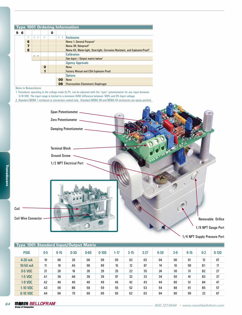
Span Potentiometer
Zero Potentiometer
Damping Potentiometer
Terminal Block
Ground Screw
1/2 NPT Electrical Port
Coil
Coil Wire Connector Removable Orifice
1/8 NPT Gauge Port
1/4 NPT Supply Pressure Port
Type 1001 Ordering Information9 6 0
Enclosures6 Nema 1, General Purpose2
7 Nema 3R, Rainproof2
8 Nema 4X, Water-tight, Dust-tight, Corrosion Resistant, and Explosion-Proof2
_ _ CalibrationSee Input / Output matrix below1
Agency Approvals0 None1 Factory Mutual and CSA Explosion Proof
Options00 None06 Fluorocarbon Elastomeric Diaphragm
Notes to Nomenclature:1. Transducer operating in the voltage mode (E/P), can be adjusted with the “span” potentiometer for any input between
0-10 VDC. The input range is limited to a minimum 4VDC difference between 100% and 0% Input voltage.2. Standard NEMA 1 enclosure is conversion coated only. Standard NEMA 3R and NEMA 4X enclosures are epoxy painted.
Type 1001 Standard Input/Output Matrix
PSIG 0-5 0-15 0-30 0-60 0-100 1-17 3-15 3-27 6-30 3-9 9-15 0-2 0-120
4-20 mA 19 06 20 08 09 05 02 03 04 00 01 13 07
10-50 mA 11 16 A5 98 89 15 12 87 14 10 90 B1 17
0-5 VDC 21 26 18 28 29 25 22 35 24 30 31 B2 27
1-5 VDC A1 36 A6 38 39 97 32 33 34 50 41 B3 37
1-9 VDC A2 46 40 48 49 45 42 43 44 60 51 B4 47
1-10 VDC A3 56 B6 58 59 55 52 53 54 88 61 B5 57
0-10 VDC A4 66 70 68 69 65 62 63 64 80 99 23 67
www.marshbellofram.com • 800.727.5646 65
Tran
sducers
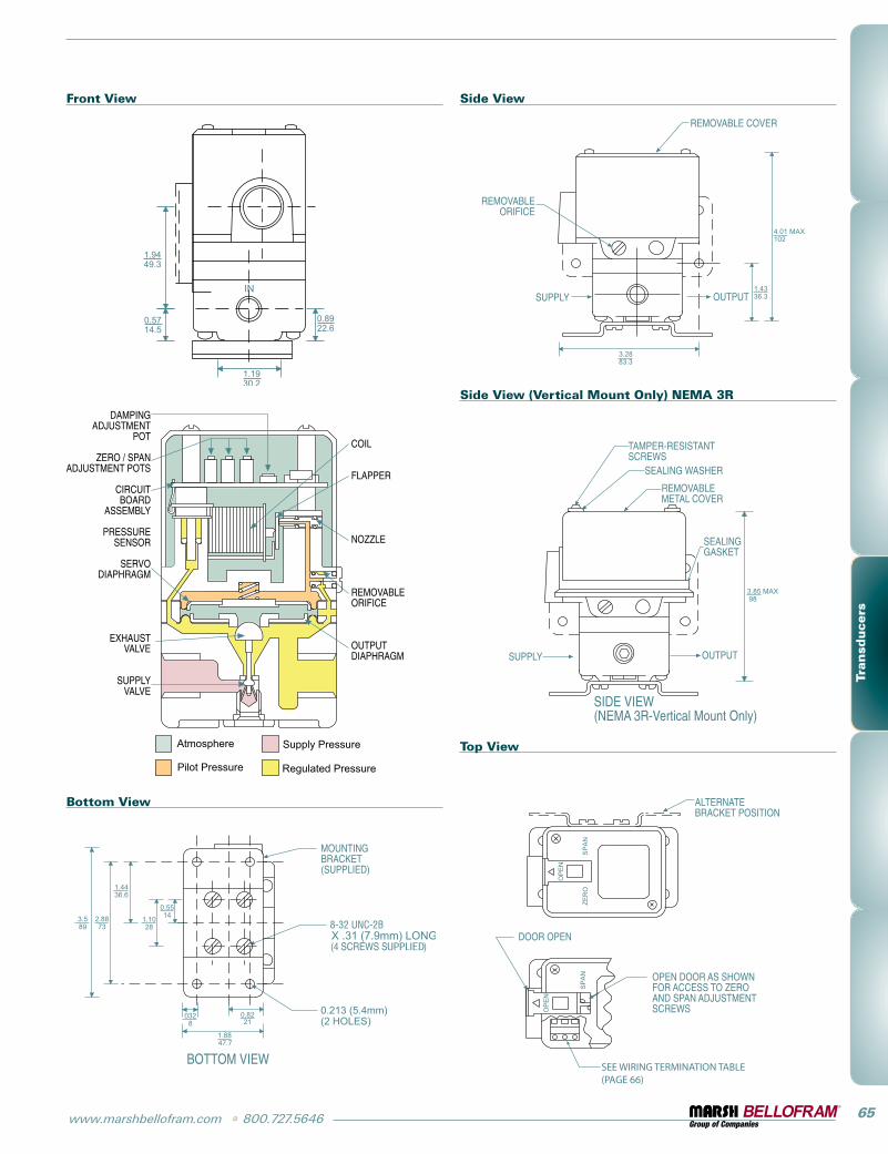
Front View Side View
Side View (Vertical Mount Only) NEMA 3R
Bottom View
Top ViewAtmosphere
Pilot Pressure
Supply Pressure
Regulated Pressure
66 800.727.5646 • www.marshbellofram.com
Tran
sducers
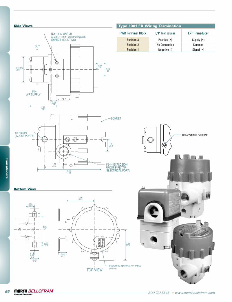
Side Views
Bottom View
Type 1001 EX Wiring Termination
pWB Terminal Block i/p Transducer E/p Transducer
position 3 positive (+) supply (+)
position 2 No Connection Common
position 1 Negative (-) signal (+)
www.marshbellofram.com • 800.727.5646 67
Tran
sducers
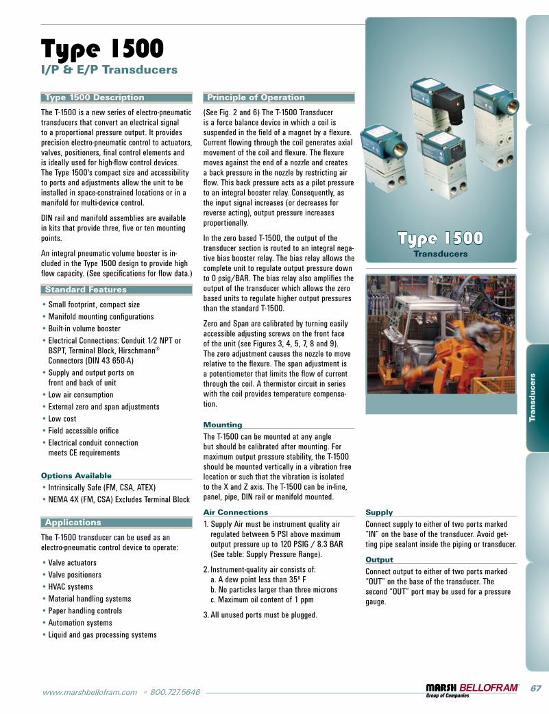
Type 1500 Description
The T-1500 is a new series of electro-pneumatic transducers that convert an electrical signal to a proportional pressure output. it provides precision electro-pneumatic control to actuators, valves, positioners, final control elements and is ideally used for high-flow control devices. The Type 1500's compact size and accessibility to ports and adjustments allow the unit to be installed in space-constrained locations or in a manifold for multi-device control.
DiN rail and manifold assemblies are available in kits that provide three, five or ten mounting points.
An integral pneumatic volume booster is in-cluded in the Type 1500 design to provide high flow capacity. (see specifications for flow data.)
Standard Features
small footprint, compact sizeManifold mounting configurationsBuilt-in volume boosterElectrical Connections: Conduit 1⁄2 NpT or BspT, Terminal Block, Hirschmann® Connectors (DiN 43 650-A)supply and output ports on front and back of unitlow air consumptionExternal zero and span adjustmentslow costField accessible orifice Electrical conduit connection meets CE requirements
Options Available
intrinsically safe (FM, CsA, ATEX) NEMA 4X (FM, CsA) Excludes Terminal Block
Applications
The T-1500 transducer can be used as an electro-pneumatic control device to operate:
Valve actuatorsValve positionersHVAC systemsMaterial handling systemspaper handling controlsAutomation systemsliquid and gas processing systems
••••
•
•••••
••
•••••••
Type 1500 I/P & E/P Transducers
Principle of Operation
(see Fig. 2 and 6) The T-1500 Transducer is a force balance device in which a coil is suspended in the field of a magnet by a flexure. Current flowing through the coil generates axial movement of the coil and flexure. The flexure moves against the end of a nozzle and creates a back pressure in the nozzle by restricting air flow. This back pressure acts as a pilot pressure to an integral booster relay. Consequently, as the input signal increases (or decreases for reverse acting), output pressure increases proportionally.
in the zero based T-1500, the output of the transducer section is routed to an integral nega-tive bias booster relay. The bias relay allows the complete unit to regulate output pressure down to 0 psig/BAR. The bias relay also amplifies the output of the transducer which allows the zero based units to regulate higher output pressures than the standard T-1500.
Zero and span are calibrated by turning easily accessible adjusting screws on the front face of the unit (see Figures 3, 4, 5, 7, 8 and 9). The zero adjustment causes the nozzle to move relative to the flexure. The span adjustment is a potentiometer that limits the flow of current through the coil. A thermistor circuit in series with the coil provides temperature compensa-tion.
Mounting
The T-1500 can be mounted at any angle but should be calibrated after mounting. For maximum output pressure stability, the T-1500 should be mounted vertically in a vibration free location or such that the vibration is isolated to the X and Z axis. The T-1500 can be in-line, panel, pipe, DiN rail or manifold mounted.
Air Connections
1. supply Air must be instrument quality air regulated between 5 psi above maximum output pressure up to 120 psig / 8.3 BAR (see table: supply pressure Range).
2. instrument-quality air consists of: a. A dew point less than 35º F b. No particles larger than three microns c. Maximum oil content of 1 ppm
3. All unused ports must be plugged.
Type 1500 Transducers
Supply
Connect supply to either of two ports marked “iN” on the base of the transducer. Avoid get-ting pipe sealant inside the piping or transducer.
Output
Connect output to either of two ports marked “OUT” on the base of the transducer. The second “OUT” port may be used for a pressure gauge.
68 800.727.5646 • www.marshbellofram.com
Tran
sducers
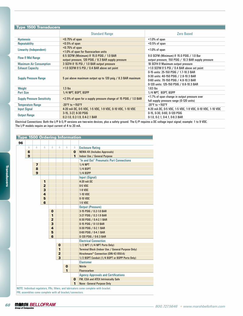
Type 1500 Transducers
standard Range Zero BasedHysteresis <0.75% of span <1.0% of spanRepeatability <0.5% of span <0.5% of span
linearity (independent)<0.75% of span <1.0% of span for fluorocarbon units
<1.0% of span
Flow @ Mid Range6.5 sCFM (Minimum) @ 15.0 psig / 1.0 BARoutput pressure, 120 psig / 8.3 BAR supply pressure
9.0 sCFM (Minimum) @ 15.0 psig / 1.0 Baroutput pressure, 150 psig / 10.3 BAR supply pressure
Maximum Air Consumption 3 sCFH @ 15 psi / 1.0 BAR output pressure 18 sCFH @ Maximum output pressureExhaust Capacity >1.0 sCFM @ 5 psi / 0.4 BAR above set point >1.0 sCFM @ 5 psi / 0.4 BAR above set point
supply pressure Range 5 psi above maximum output up to 120 psig / 8.3 BAR maximum
0-15 units: 25-150 psig / 1.7-10.3 BAR0-30 units: 40-150 psig / 2.8-10.3 BAR0-60 units: 70-150 psig / 4.8-10.3 BAR0-120 units: 125-150 psig / 8.6-10.3 BAR
Weight 1.3 lbs 1.63 lbsport size 1/4 NpT, BspT, Bspp 1/4 NpT, BspT, Bspp
supply pressure sensitivity <2.5% of span for a supply pressure change of 15 psig / 1.0 BAR<1.7% of span change in output pressure over full supply pressure range (0-120 units)
Temperature Range -20°F to +150°F -20°F to +150°Finput signal 4-20 mA DC, 0-5 VDC, 1-5 VDC, 1-9 VDC, 0-10 VDC, 1-10 VDC 4-20 mA DC, 0-5 VDC, 1-5 VDC, 1-9 VDC, 0-10 VDC, 1-10 VDC
Output Range3-15, 3-27, 6-30 psig 0.2-1.0, 0.2-1.9, 0.4-2.1 BAR
0-15, 0-30, 0-60, 0-120 psig0-1.0, 0-2.1, 0-4.1, 0-8.3 BAR
Electrical Connections: Both the i/p & E/p versions are two-wire devices, plus a safety ground. The E/p requires a DC voltage input signal; example: 1 to 9 VDC. The i/p models require an input current of 4 to 20 mA.
Type 1500 Ordering Information96
Enclosure Rating6 0 NEMA 4X (includes Approvals)9 1 indoor Use / general purpose
“in and Out” pneumatic port Connections7 1/4 NpT8 1/4 BspT9 1/4 Bspp
input (signal)1 4-20 mA DC2 0-5 VDC3 1-9 VDC4 1-10 VDC5 0-10 VDC6 1-5 VDC
Output (pressure)0 3-15 psig / 0.2-1.0 BAR1 3-27 psig / 0.2-1.9 BAR2 6-30 psig / 0.4-2.1 BAR3 0-15 psig / 0-1.0 BAR4 0-30 psig / 0-2.1 BAR5 0-60 psig / 0-4.1 BAR6 0-120 psig / 0-8.3 BAR
Electrical Connection0 1/2 NpT (1/4 NpT ports Only)
1 Terminal Block (indoor Use / general purpose Only)
2 Hirschmann® Connection (DiN 43 650-A)3 1/2 BspT Conduit (1/4 BspT or Bspp ports Only)
Elastomer0 Nitrile1 Fluorocarbon
Agency Approvals and Certifications0 FM, CsA and ATEX intrinsically safe
1 None - general purpose Only
NOTE: individual regulators, FRs, filters, and lubricators come complete with bracket.FRl assemblies come complete with all bracket/connectors.
www.marshbellofram.com • 800.727.5646 69
Tran
sducers
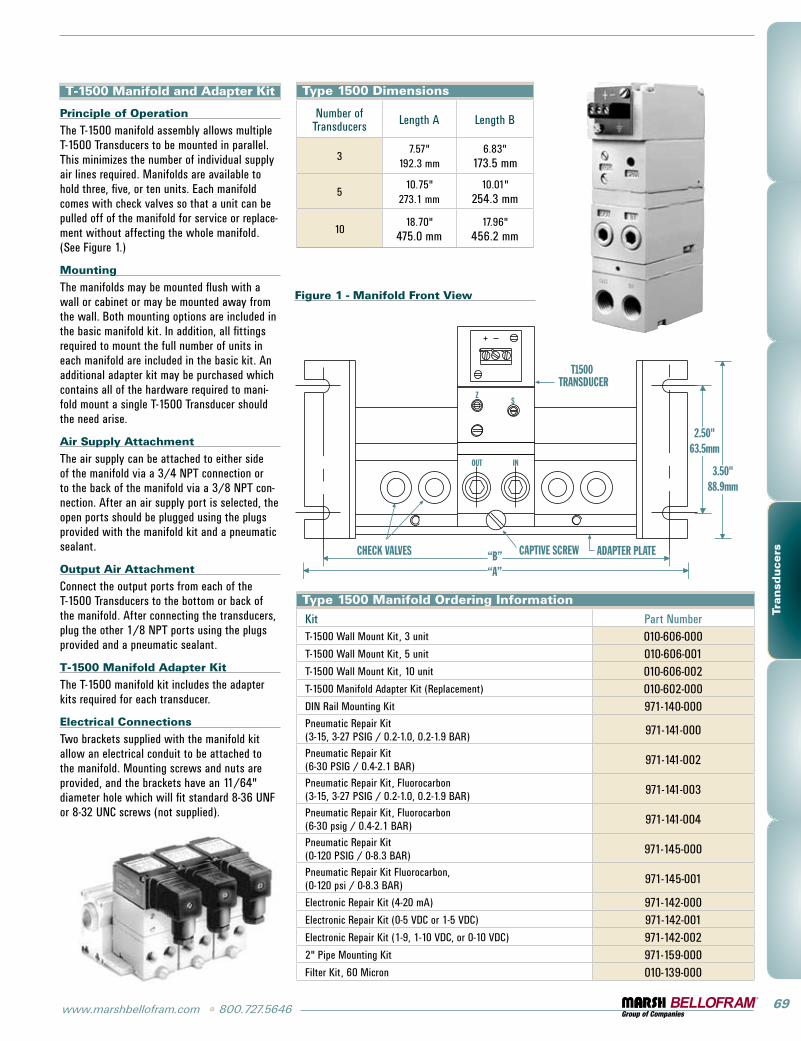
T-1500 Manifold and Adapter Kit
Principle of Operation
The T-1500 manifold assembly allows multiple T-1500 Transducers to be mounted in parallel. This minimizes the number of individual supply air lines required. Manifolds are available to hold three, five, or ten units. Each manifold comes with check valves so that a unit can be pulled off of the manifold for service or replace-ment without affecting the whole manifold. (see Figure 1.)
Mounting
The manifolds may be mounted flush with a wall or cabinet or may be mounted away from the wall. Both mounting options are included in the basic manifold kit. in addition, all fittings required to mount the full number of units in each manifold are included in the basic kit. An additional adapter kit may be purchased which contains all of the hardware required to mani-fold mount a single T-1500 Transducer should the need arise.
Air Supply Attachment
The air supply can be attached to either side of the manifold via a 3/4 NpT connection or to the back of the manifold via a 3/8 NpT con-nection. After an air supply port is selected, the open ports should be plugged using the plugs provided with the manifold kit and a pneumatic sealant.
Output Air Attachment
Connect the output ports from each of the T-1500 Transducers to the bottom or back of the manifold. After connecting the transducers, plug the other 1/8 NpT ports using the plugs provided and a pneumatic sealant.
T-1500 Manifold Adapter Kit
The T-1500 manifold kit includes the adapter kits required for each transducer.
Electrical Connections
Two brackets supplied with the manifold kit allow an electrical conduit to be attached to the manifold. Mounting screws and nuts are provided, and the brackets have an 11/64" diameter hole which will fit standard 8-36 UNF or 8-32 UNC screws (not supplied).
ADAPTER PLATECAPTIVE SCREW
T1500TRANSDUCER
ZS
INOUT
CHECK VALVES “B”“A”
2.50"63.5mm
3.50"88.9mm
Figure 1 - Manifold Front View
Type 1500 Dimensions
Number of Transducers length A length B
37.57"
192.3 mm6.83"
173.5 mm
510.75"
273.1 mm10.01"
254.3 mm
1018.70"
475.0 mm17.96"
456.2 mm
Type 1500 Manifold Ordering Information
Kit part NumberT-1500 Wall Mount Kit, 3 unit 010-606-000T-1500 Wall Mount Kit, 5 unit 010-606-001T-1500 Wall Mount Kit, 10 unit 010-606-002T-1500 Manifold Adapter Kit (Replacement) 010-602-000DiN Rail Mounting Kit 971-140-000pneumatic Repair Kit (3-15, 3-27 psig / 0.2-1.0, 0.2-1.9 BAR) 971-141-000
pneumatic Repair Kit (6-30 psig / 0.4-2.1 BAR) 971-141-002
pneumatic Repair Kit, Fluorocarbon(3-15, 3-27 psig / 0.2-1.0, 0.2-1.9 BAR) 971-141-003
pneumatic Repair Kit, Fluorocarbon (6-30 psig / 0.4-2.1 BAR) 971-141-004
pneumatic Repair Kit (0-120 psig / 0-8.3 BAR) 971-145-000
pneumatic Repair Kit Fluorocarbon, (0-120 psi / 0-8.3 BAR) 971-145-001
Electronic Repair Kit (4-20 mA) 971-142-000Electronic Repair Kit (0-5 VDC or 1-5 VDC) 971-142-001 Electronic Repair Kit (1-9, 1-10 VDC, or 0-10 VDC) 971-142-0022" pipe Mounting Kit 971-159-000Filter Kit, 60 Micron 010-139-000
70 800.727.5646 • www.marshbellofram.com
Tran
sducers
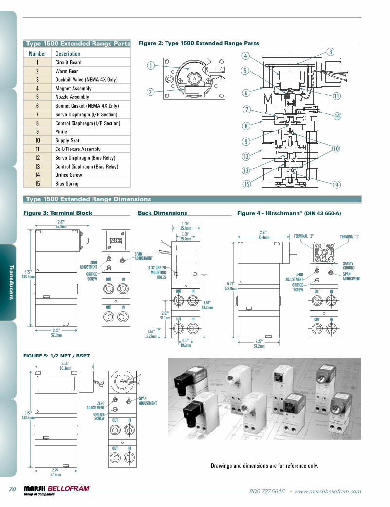
Type 1500 Extended Range Parts
Number Description
1 Circuit Board
2 Worm gear
3 Duckbill Valve (NEMA 4X Only)
4 Magnet Assembly
5 Nozzle Assembly
6 Bonnet gasket (NEMA 4X Only)
7 servo Diaphragm (i/p section)
8 Control Diaphragm (i/p section)
9 pintle
10 supply seat
11 Coil/Flexure Assembly
12 servo Diaphragm (Bias Relay)
13 Control Diaphragm (Bias Relay)
14 Orifice screw
15 Bias spring
Figure 2: Type 1500 Extended Range Parts
Figure 3: Terminal Block
IN
IN
OUT
OUT
Z SPANADJUSTMENT
ORIFICESCREW
ZEROADJUSTMENT
S
2.87"62.9mm
5.27"133.9mm
2.25"57.2mm
Back Dimensions
IN
OUT IN
OUT
10-32 UNF-2BMOUNTING
HOLES
3.51"89.2mm
2.01"51.1mm
0.52"13.22mm
1.00"25.4mm
1.00"25.4mm
0.77"19.6mm
Figure 4 - Hirschmann® (DIN 43 650-A)
IN
IN
OUT
OUT
TERMINAL "2" TERMINAL "1"
SAFETYGROUNDSPANADJUSTMENT
SZ
ZEROADJUSTMENT
ORIFICESCREW
5.27"133.9mm
2.77"70.4mm
2.25"57.2mm
FIGURE 5: 1/2 NPT / BSPT
2.25"57.2mm
SPANADJUSTMENT
S
ZEROADJUSTMENT
ORIFICESCREW
Z
IN
IN
OUT
OUT
5.27"133.9mm
3.16"80.3mm
Drawings and dimensions are for reference only.
Type 1500 Extended Range Dimensions
www.marshbellofram.com • 800.727.5646 71
Tran
sducers
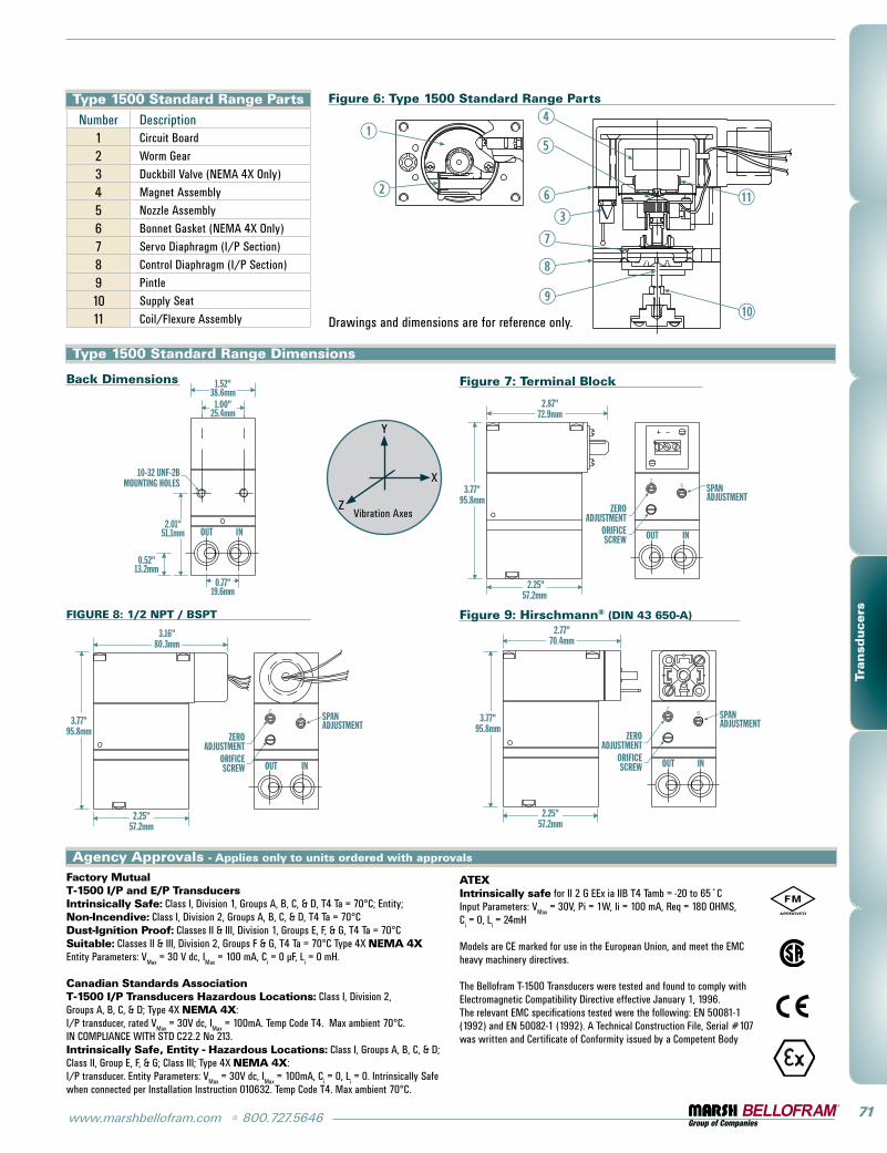
Type 1500 Standard Range Parts
Number Description1 Circuit Board
2 Worm gear
3 Duckbill Valve (NEMA 4X Only)
4 Magnet Assembly
5 Nozzle Assembly
6 Bonnet gasket (NEMA 4X Only)
7 servo Diaphragm (i/p section)
8 Control Diaphragm (i/p section)
9 pintle
10 supply seat
11 Coil/Flexure Assembly
Figure 6: Type 1500 Standard Range Parts
Figure 7: Terminal BlockBack Dimensions
Figure 9: Hirschmann® (DIN 43 650-A)
Type 1500 Standard Range Dimensions
FIGURE 8: 1/2 NPT / BSPT
INOUT
1.52"38.6mm
1.00"25.4mm
10-32 UNF-2BMOUNTING HOLES
0.77"19.6mm
2.01"51.1mm
0.52"13.2mm
ZEROADJUSTMENT
ORIFICESCREW
2.25"57.2mm
SPANADJUSTMENT
SZ
INOUT
3.77"95.8mm
2.87"72.9mm
2.25"57.2mm
SPANADJUSTMENT3.77"
95.8mm
3.16"80.3mm
ZEROADJUSTMENT
ORIFICESCREW
SZ
INOUT
ZEROADJUSTMENT
ORIFICESCREW
2.25"57.2mm
SPANADJUSTMENT
3.77"95.8mm
2.77"70.4mm
SZ
OUT IN
Agency Approvals - Applies only to units ordered with approvals
Vibration Axes
Y
X
Z
Drawings and dimensions are for reference only.
Factory MutualT-1500 I/P and E/P TransducersIntrinsically Safe: Class i, Division 1, groups A, B, C, & D, T4 Ta = 70°C; Entity; Non-Incendive: Class i, Division 2, groups A, B, C, & D, T4 Ta = 70°CDust-Ignition Proof: Classes ii & iii, Division 1, groups E, F, & g, T4 Ta = 70°CSuitable: Classes ii & iii, Division 2, groups F & g, T4 Ta = 70°C Type 4X NEMA 4XEntity parameters: V
Max = 30 V dc, i
Max = 100 mA, C
i = 0 μF, l
i = 0 mH.
Canadian Standards AssociationT-1500 I/P Transducers Hazardous Locations: Class i, Division 2, groups A, B, C, & D; Type 4X NEMA 4X: i/p transducer, rated V
Max = 30V dc, i
Max = 100mA. Temp Code T4. Max ambient 70°C.
iN COMpliANCE WiTH sTD C22.2 No 213.Intrinsically Safe, Entity - Hazardous Locations: Class i, groups A, B, C, & D; Class ii, group E, F, & g; Class iii; Type 4X NEMA 4X: i/p transducer. Entity parameters: V
Max = 30V dc, i
Max = 100mA, C
i = 0, l
i = 0. intrinsically safe
when connected per installation instruction 010632. Temp Code T4. Max ambient 70°C.
ATEXIntrinsically safe for ii 2 g EEx ia iiB T4 Tamb = -20 to 65˚Cinput parameters: V
Max = 30V, pi = 1W, ii = 100 mA, Req = 180 OHMs,
Ci = 0, l
i = 24mH
Models are CE marked for use in the European Union, and meet the EMC heavy machinery directives.
The Bellofram T-1500 Transducers were tested and found to comply with Electromagnetic Compatibility Directive effective January 1, 1996. The relevant EMC specifications tested were the following: EN 50081-1 (1992) and EN 50082-1 (1992). A Technical Construction File, serial #107 was written and Certificate of Conformity issued by a Competent Body
72 800.727.5646 • www.marshbellofram.com
Tran
sducers
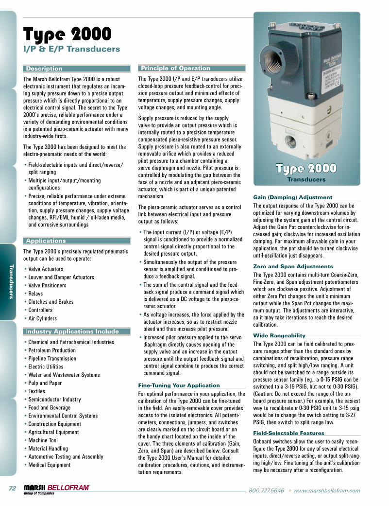
Description
The Marsh Bellofram Type 2000 is a robust electronic instrument that regulates an incom-ing supply pressure down to a precise output pressure which is directly proportional to an electrical control signal. The secret to the Type 2000’s precise, reliable performance under a variety of demanding environmental conditions is a patented piezo-ceramic actuator with many industry-wide firsts.
The Type 2000 has been designed to meet the electro-pneumatic needs of the world:
Field-selectable inputs and direct/reverse/split rangingMultiple input/output/mounting configurationsprecise, reliable performance under extreme conditions of temperature, vibration, orienta-tion, supply pressure changes, supply voltage changes, RFi/EMi, humid / oil-laden media, and corrosive surroundings
Applications
The Type 2000’s precisely regulated pneumatic output can be used to operate:
Valve Actuatorslouver and Damper ActuatorsValve positionersRelaysClutches and BrakesControllersAir Cylinders
industry Applications Include
Chemical and petrochemical industriespetroleum productionpipeline Transmission Electric UtilitiesWater and Wastewater systemspulp and paperTextilessemiconductor industryFood and BeverageEnvironmental Control systemsConstruction EquipmentAgricultural EquipmentMachine ToolMaterial HandlingAutomotive Testing and AssemblyMedical Equipment
•
•
•
•••••••
••••••••••••••••
Type 2000 I/P & E/P Transducers
Principle of Operation
The Type 2000 i/p and E/p transducers utilize closed-loop pressure feedback-control for preci-sion pressure output and minimized effects of temperature, supply pressure changes, supply voltage changes, and mounting angle.
supply pressure is reduced by the supply valve to provide an output pressure which is internally routed to a precision temperature compensated piezo-resistive pressure sensor. supply pressure is also routed to an externally removable orifice which provides a reduced pilot pressure to a chamber containing a servo diaphragm and nozzle. pilot pressure is controlled by modulating the gap between the face of a nozzle and an adjacent piezo-ceramic actuator, which is part of a unique patented mechanism.
The piezo-ceramic actuator serves as a control link between electrical input and pressure output as follows:
The input current (i/p) or voltage (E/p) signal is conditioned to provide a normalized control signal directly proportional to the desired pressure output.simultaneously the output of the pressure sensor is amplified and conditioned to pro-duce a feedback signal.The sum of the control signal and the feed-back signal produce a command signal which is delivered as a DC voltage to the piezo-ce-ramic actuator.As voltage increases, the force applied by the actuator increases, so as to restrict nozzle bleed and thus increase pilot pressure.increased pilot pressure applied to the servo diaphragm directly causes opening of the supply valve and an increase in the output pressure until the output feedback signal and control signal combine to produce the correct command signal.
Fine-Tuning Your Application
For optimal performance in your application, the calibration of the Type 2000 can be fine-tuned in the field. An easily-removable cover provides access to the isolated electronics. All potenti-ometers, connections, jumpers, and switches are clearly marked on the circuit board or on the handy chart located on the inside of the cover. The three elements of calibration (gain, Zero, and span) are described below. Consult the Type 2000 User’s Manual for detailed calibration procedures, cautions, and instrumen-tation requirements.
•
•
•
•
•
Type 2000 Transducers
Gain (Damping) Adjustment
The output response of the Type 2000 can be optimized for varying downstream volumes by adjusting the system gain of the control circuit. Adjust the gain pot counterclockwise for in-creased gain; clockwise for increased oscillation damping. For maximum allowable gain in your application, the pot should be turned clockwise until oscillation just disappears.
Zero and Span Adjustments
The Type 2000 contains multi-turn Coarse-Zero, Fine-Zero, and span adjustment potentiometers which are clockwise positive. Adjustment of either Zero pot changes the unit’s minimum output while the span pot changes the maxi-mum output. The adjustments are interactive, so it may take iterations to reach the desired calibration.
Wide Rangeability
The Type 2000 can be field calibrated to pres-sure ranges other than the standard ones by combinations of recalibration, pressure range switching, and split high/low ranging. A unit should not be switched to a range outside its pressure sensor family (eg., a 0-15 psig can be switched to a 3-15 psig, but not to 0-30 psig). (Caution: Do not exceed the range of the on-board pressure sensor.) For example, the easiest way to recalibrate a 0-30 psig unit to 3-15 psig would be to change the switch setting to 3-27 psig, then switch to split range low.
Field-Selectable Features
Onboard switches allow the user to easily recon-figure the Type 2000 for any of several electrical inputs, direct/reverse acting, or output split-rang-ing high/low. Fine tuning of the unit’s calibration may be necessary after a reconfiguration.
www.marshbellofram.com • 800.727.5646 73
Tran
sducers
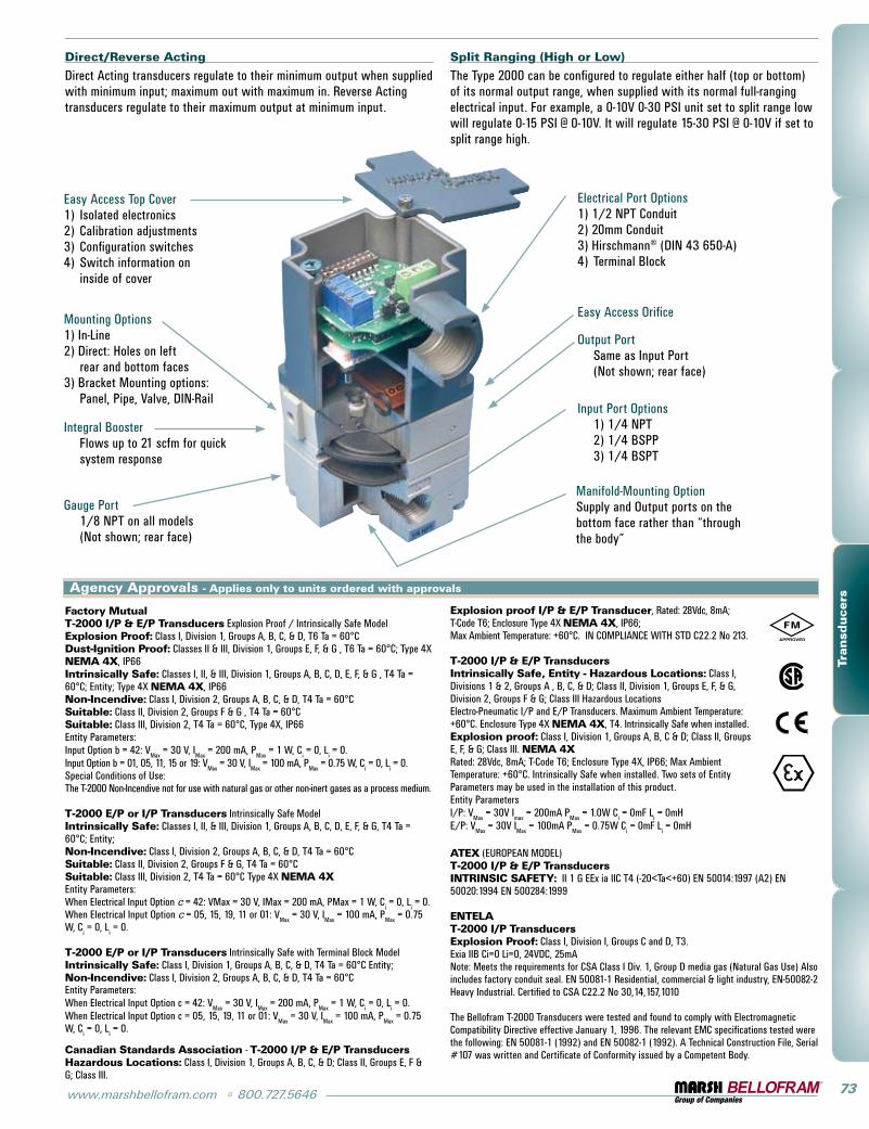
Easy Access Top Cover1) isolated electronics2) Calibration adjustments3) Configuration switches4) switch information on
inside of cover
Mounting Options1) in-line2) Direct: Holes on left
rear and bottom faces3) Bracket Mounting options:
panel, pipe, Valve, DiN-Rail
integral Booster Flows up to 21 scfm for quick
system response
gauge port 1/8 NpT on all models (Not shown; rear face)
Manifold-Mounting Option supply and Output ports on the bottom face rather than “through the body”
Electrical port Options1) 1/2 NpT Conduit2) 20mm Conduit3) Hirschmann® (DiN 43 650-A)4) Terminal Block
Easy Access Orifice
Output port same as input port (Not shown; rear face)
input port Options 1) 1/4 NpT
2) 1/4 Bspp 3) 1/4 BspT
Agency Approvals - Applies only to units ordered with approvals
Factory MutualT-2000 I/P & E/P Transducers Explosion proof / intrinsically safe ModelExplosion Proof: Class i, Division 1, groups A, B, C, & D, T6 Ta = 60°CDust-Ignition Proof: Classes ii & iii, Division 1, groups E, F, & g , T6 Ta = 60°C; Type 4X NEMA 4X, ip66Intrinsically Safe: Classes i, ii, & iii, Division 1, groups A, B, C, D, E, F, & g , T4 Ta = 60°C; Entity; Type 4X NEMA 4X, ip66Non-Incendive: Class i, Division 2, groups A, B, C, & D, T4 Ta = 60°C Suitable: Class ii, Division 2, groups F & g , T4 Ta = 60°CSuitable: Class iii, Division 2, T4 Ta = 60°C, Type 4X, ip66Entity parameters:input Option b = 42: V
Max = 30 V, i
Max = 200 mA, p
Max = 1 W, C
i = 0, l
i = 0.
input Option b = 01, 05, 11, 15 or 19: VMax
= 30 V, iMax
= 100 mA, pMax
= 0.75 W, Ci = 0, l
i = 0.
special Conditions of Use:The T-2000 Non-incendive not for use with natural gas or other non-inert gases as a process medium.
T-2000 E/P or I/P Transducers intrinsically safe ModelIntrinsically Safe: Classes i, ii, & iii, Division 1, groups A, B, C, D, E, F, & g, T4 Ta = 60°C; Entity; Non-Incendive: Class i, Division 2, groups A, B, C, & D, T4 Ta = 60°C Suitable: Class ii, Division 2, groups F & g, T4 Ta = 60°CSuitable: Class iii, Division 2, T4 Ta = 60°C Type 4X NEMA 4XEntity parameters:When Electrical input Option c = 42: VMax = 30 V, iMax = 200 mA, pMax = 1 W, C
i = 0, l
i = 0.
When Electrical input Option c = 05, 15, 19, 11 or 01: VMax
= 30 V, iMax
= 100 mA, pMax
= 0.75 W, C
i = 0, l
i = 0.
T-2000 E/P or I/P Transducers intrinsically safe with Terminal Block ModelIntrinsically Safe: Class i, Division 1, groups A, B, C, & D, T4 Ta = 60°C Entity; Non-Incendive: Class i, Division 2, groups A, B, C, & D, T4 Ta = 60°CEntity parameters:When Electrical input Option c = 42: V
Max = 30 V, i
Max = 200 mA, p
Max = 1 W, C
i = 0, l
i = 0.
When Electrical input Option c = 05, 15, 19, 11 or 01: VMax
= 30 V, iMax
= 100 mA, pMax
= 0.75 W, C
i = 0, l
i = 0.
Canadian Standards Association - T-2000 I/P & E/P TransducersHazardous Locations: Class i, Division 1, groups A, B, C, & D; Class ii, groups E, F & g; Class iii.
Explosion proof I/P & E/P Transducer, Rated: 28Vdc, 8mA; T-Code T6; Enclosure Type 4X NEMA 4X, ip66; Max Ambient Temperature: +60°C. iN COMpliANCE WiTH sTD C22.2 No 213.
T-2000 I/P & E/P TransducersIntrinsically Safe, Entity - Hazardous Locations: Class i, Divisions 1 & 2, groups A , B, C, & D; Class ii, Division 1, groups E, F, & g, Division 2, groups F & g; Class iii Hazardous locationsElectro-pneumatic i/p and E/p Transducers. Maximum Ambient Temperature: +60°C. Enclosure Type 4X NEMA 4X, T4. intrinsically safe when installed. Explosion proof: Class i, Division 1, groups A, B, C & D; Class ii, groups E, F, & g; Class iii. NEMA 4XRated: 28Vdc, 8mA; T-Code T6; Enclosure Type 4X, ip66; Max Ambient Temperature: +60°C. intrinsically safe when installed. Two sets of Entity parameters may be used in the installation of this product. Entity parameters i/p: V
Max = 30V i
max = 200mA p
Max = 1.0W C
i = 0mF l
i = 0mH
E/p: VMax
= 30V iMax
= 100mA pMax
= 0.75W Ci = 0mF l
i = 0mH
Direct/Reverse Acting
Direct Acting transducers regulate to their minimum output when supplied with minimum input; maximum out with maximum in. Reverse Acting transducers regulate to their maximum output at minimum input.
Split Ranging (High or Low)
The Type 2000 can be configured to regulate either half (top or bottom) of its normal output range, when supplied with its normal full-ranging electrical input. For example, a 0-10V 0-30 psi unit set to split range low will regulate 0-15 psi @ 0-10V. it will regulate 15-30 psi @ 0-10V if set to split range high.
ATEX (EUROpEAN MODEl)T-2000 I/P & E/P TransducersINTRINSIC SAFETY: ii 1 g EEx ia iiC T4 (-20<Ta<+60) EN 50014:1997 (A2) EN 50020:1994 EN 500284:1999
ENTELAT-2000 I/P TransducersExplosion Proof: Class i, Division i, groups C and D, T3.Exia iiB Ci=0 li=0, 24VDC, 25mANote: Meets the requirements for CsA Class i Div. 1, group D media gas (Natural gas Use) Also includes factory conduit seal. EN 50081-1 Residential, commercial & light industry, EN-50082-2 Heavy industrial. Certified to CsA C22.2 No 30,14,157,1010
The Bellofram T-2000 Transducers were tested and found to comply with Electromagnetic Compatibility Directive effective January 1, 1996. The relevant EMC specifications tested were the following: EN 50081-1 (1992) and EN 50082-1 (1992). A Technical Construction File, serial #107 was written and Certificate of Conformity issued by a Competent Body.
74 800.727.5646 • www.marshbellofram.com
Tran
sducers
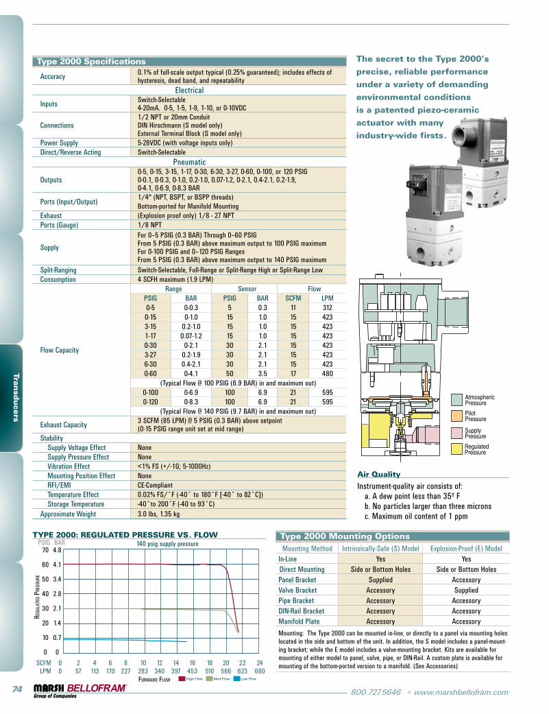
Type 2000 Specifications
Accuracy 0.1% of full-scale output typical (0.25% guaranteed); includes effects of hysteresis, dead band, and repeatability
Electrical
inputs switch-selectable4-20mA. 0-5, 1-5, 1-9, 1-10, or 0-10VDC
Connections1/2 NpT or 20mm ConduitDiN Hirschmann (s model only)External Terminal Block (s model only)
power supply 5-28VDC (with voltage inputs only)Direct/Reverse Acting switch-selectable
pneumatic
Outputs0-5, 0-15, 3-15, 1-17, 0-30, 6-30, 3-27, 0-60, 0-100, or 120 psig0-0.1, 0-0.3, 0-1.0, 0.2-1.0, 0.07-1.2, 0-2.1, 0.4-2.1, 0.2-1.9,0-4.1, 0-6.9, 0-8.3 BAR
ports (input/Output)1/4" (NpT, BspT, or Bspp threads) Bottom-ported for Manifold Mounting
Exhaust (Explosion proof only) 1/8 - 27 NpTports (gauge) 1/8 NpT
supply
For 0–5 psig (0.3 BAR) Through 0–60 psig From 5 psig (0.3 BAR) above maximum output to 100 psig maximum For 0-100 psig and 0–120 psig Ranges From 5 psig (0.3 BAR) above maximum output to 140 psig maximum
split-Ranging switch-selectable, Full-Range or split-Range High or split-Range lowConsumption 4 sCFH maximum (1.9 lpM)
Flow Capacity
Range sensor Flowpsig BAR psig BAR sCFM lpM0-5 0-0.3 5 0.3 11 3120-15 0-1.0 15 1.0 15 4233-15 0.2-1.0 15 1.0 15 4231-17 0.07-1.2 15 1.0 15 4230-30 0-2.1 30 2.1 15 4233-27 0.2-1.9 30 2.1 15 4236-30 0.4-2.1 30 2.1 15 4230-60 0-4.1 50 3.5 17 480
(Typical Flow @ 100 psig (6.9 BAR) in and maximum out)0-100 0-6.9 100 6.9 21 5950-120 0-8.3 100 6.9 21 595
(Typical Flow @ 140 psig (9.7 BAR) in and maximum out)
Exhaust Capacity 3 sCFM (85 lpM) @ 5 psig (0.3 BAR) above setpoint(0-15 psig range unit set at mid range)
stabilitysupply Voltage Effect Nonesupply pressure Effect NoneVibration Effect <1% Fs (+/-1g; 5-1000Hz)Mounting position Effect NoneRFi/EMi CE-CompliantTemperature Effect 0.02% Fs/˚F (-40˚ to 180˚F [-40˚ to 82˚C])storage Temperature -40˚to 200˚F (-40 to 93˚C)
Approximate Weight 3.0 lbs, 1.35 kg
The secret to the Type 2000’s precise, reliable performance under a variety of demanding environmental conditions is a patented piezo-ceramic actuator with many industry-wide firsts.
TYPE 2000: REGULATED PRESSURE VS. FLOW
70 4.8
60 4.1
50 3.4
40 2.8
30 2.1
20 1.4
10 0.7
0 0
sCFM 0 2 4 6 8 10 12 14 16 18 20 22 24 lpM 0 57 113 170 227 283 340 397 453 510 566 623 680 FoRwaRd Flow
psig BAR
High Flow Med Flow Low Flow
Regu
late
d PR
essu
Re
140 psig supply pressureType 2000 Mounting OptionsMounting Method intrinsically-safe (s) Model Explosion-proof (E) Model
in-line Yes YesDirect Mounting side or Bottom Holes side or Bottom Holespanel Bracket supplied AccessoryValve Bracket Accessory suppliedpipe Bracket Accessory AccessoryDiN-Rail Bracket Accessory AccessoryManifold plate Accessory Accessory
Mounting: The Type 2000 can be mounted in-line, or directly to a panel via mounting holes located in the side and bottom of the unit. in addition, the s model includes a panel-mount-ing bracket; while the E model includes a valve-mounting bracket. Kits are available for mounting of either model to panel, valve, pipe, or DiN-Rail. A custom plate is available for mounting of the bottom-ported version to a manifold. (see Accessories)
Air Quality
instrument-quality air consists of: a. A dew point less than 35º F b. No particles larger than three microns c. Maximum oil content of 1 ppm
www.marshbellofram.com • 800.727.5646 75
Tran
sducers
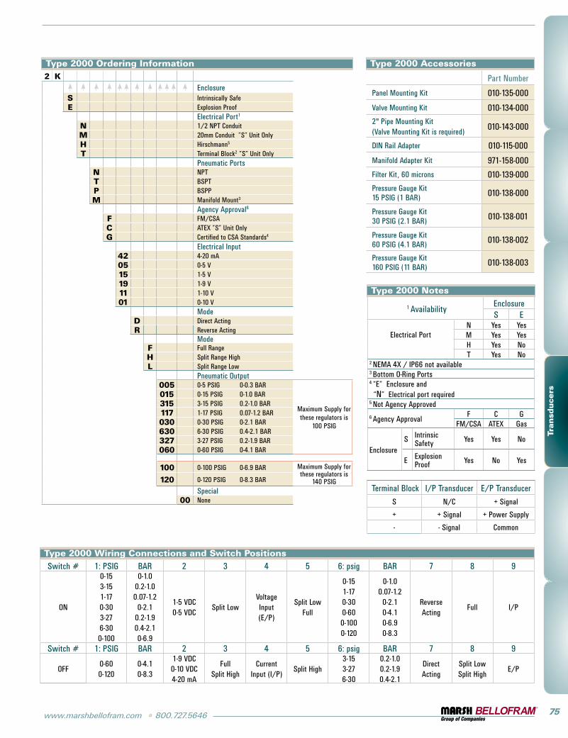
Type 2000 Ordering Information2 K
EnclosureS intrinsically safeE Explosion proof
Electrical port1
N 1/2 NpT ConduitM 20mm Conduit ”s” Unit OnlyH Hirschmann5
T Terminal Block2 ”s” Unit Onlypneumatic ports
N NpTT BspTP BsppM Manifold Mount3
Agency Approval6
F FM/CsAC ATEX ”s” Unit OnlyG Certified to CsA standards4
Electrical input42 4-20 mA05 0-5 V15 1-5 V19 1-9 V 11 1-10 V01 0-10 V
ModeD Direct ActingR Reverse Acting
ModeF Full RangeH split Range HighL split Range low
pneumatic Output005 0-5 psig 0-0.3 BAR
Maximum supply for these regulators is
100 psig
015 0-15 psig 0-1.0 BAR315 3-15 psig 0.2-1.0 BAR117 1-17 psig 0.07-1.2 BAR030 0-30 psig 0-2.1 BAR630 6-30 psig 0.4-2.1 BAR327 3-27 psig 0.2-1.9 BAR060 0-60 psig 0-4.1 BAR
100 0-100 psig 0-6.9 BAR Maximum supply for these regulators is
140 psig120 0-120 psig 0-8.3 BAR
special00 None
Type 2000 Accessories
part Number
panel Mounting Kit 010-135-000
Valve Mounting Kit 010-134-000
2" pipe Mounting Kit(Valve Mounting Kit is required)
010-143-000
DiN Rail Adapter 010-115-000
Manifold Adapter Kit 971-158-000
Filter Kit, 60 microns 010-139-000
pressure gauge Kit 15 psig (1 BAR) 010-138-000
pressure gauge Kit30 psig (2.1 BAR) 010-138-001
pressure gauge Kit60 psig (4.1 BAR) 010-138-002
pressure gauge Kit160 psig (11 BAR) 010-138-003
Type 2000 Notes
1 AvailabilityEnclosures E
Electrical port
N Yes YesM Yes YesH Yes NoT Yes No
2 NEMA 4X / ip66 not available3 Bottom O-Ring ports4 “E” Enclosure and “N” Electrical port required5 Not Agency Approved
6 Agency ApprovalF C g
FM/CsA ATEX gas
Enclosures intrinsic
safety Yes Yes No
E Explosion proof Yes No Yes
Type 2000 Wiring Connections and Switch Positionsswitch # 1: psig BAR 2 3 4 5 6: psig BAR 7 8 9
ON
0-153-151-170-303-276-300-100
0-1.00.2-1.00.07-1.2
0-2.10.2-1.90.4-2.10-6.9
1-5 VDC0-5 VDC
split lowVoltageinput(E/p)
split lowFull
0-151-170-300-600-1000-120
0-1.00.07-1.2
0-2.10-4.10-6.90-8.3
ReverseActing
Full i/p
switch # 1: psig BAR 2 3 4 5 6: psig BAR 7 8 9
OFF0-600-120
0-4.10-8.3
1-9 VDC0-10 VDC4-20 mA
Fullsplit High
Currentinput (i/p)
split High3-153-276-30
0.2-1.00.2-1.90.4-2.1
DirectActing
split lowsplit High
E/p
Terminal Block i/p Transducer E/p Transducer
s N/C + signal
+ + signal + power supply
- - signal Common
76 800.727.5646 • www.marshbellofram.com
Tran
sducers
1.060
4.780
.570 TYP
2X 8-32 UNC-2BX .375 DEEP
MOUNTING HOLES
OUT
2.225
2.939
2.307
M
arsh
Bellofram
.360.716
1.893
.550
1.100
2X M3X0.5X .250 DEEP
1/4-18 NPT TYP
3.883
1/2-14 NPT
IN
OUT
6.01
[152.6]
1.78
[45.2]
0.68 [17.3]
0.57 [14.5]
3.92
[99.5]
1.37
[34.7]
0.55 [14.0]
1.10
[27.9]
2.06
[52.3]
2.12
[53.8]
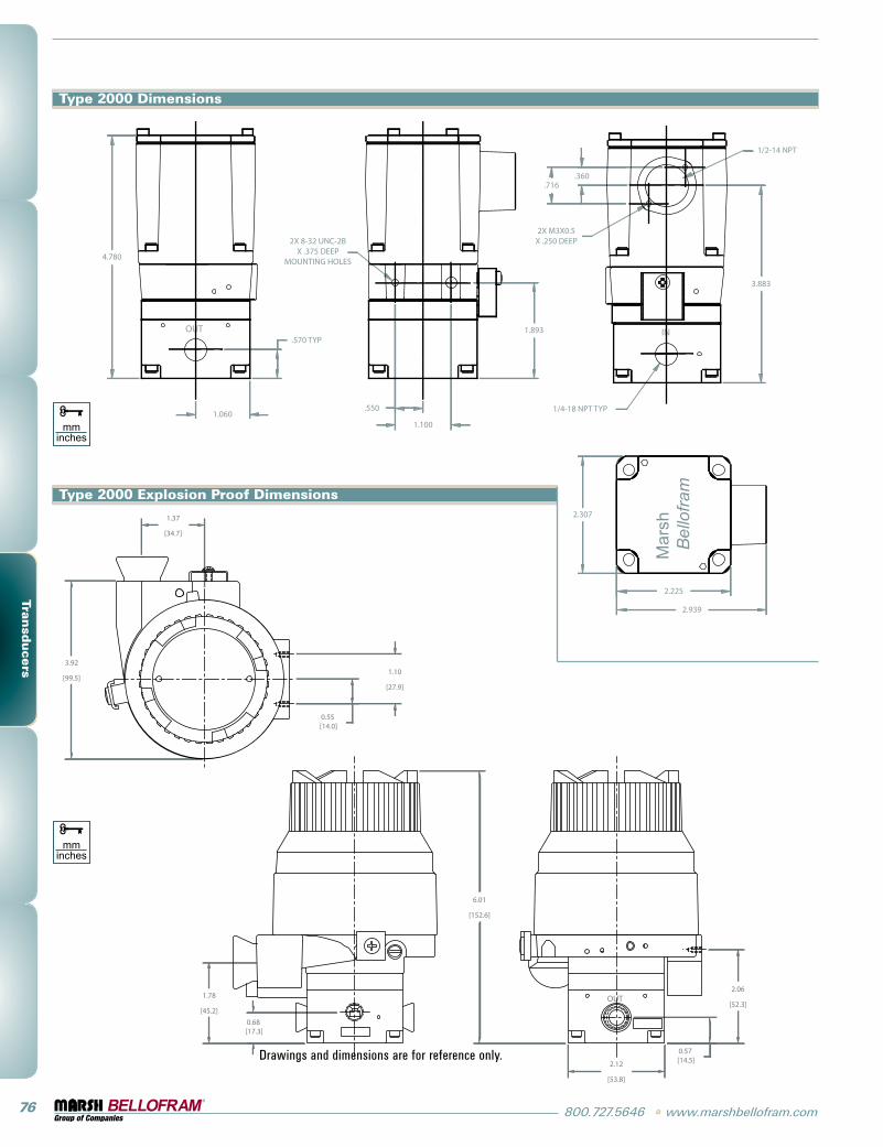
Type 2000 Dimensions
Drawings and dimensions are for reference only.
Type 2000 Explosion Proof Dimensions
www.marshbellofram.com • 800.727.5646 77
Tran
sducers
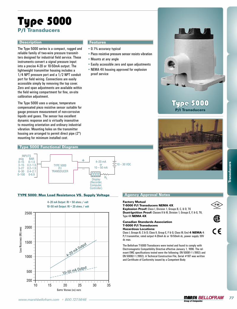
Description
The Type 5000 series is a compact, rugged and reliable family of two-wire pressure transmit-ters designed for industrial field service. These instruments convert a signal pressure input into a precise 4-20 or 10-50mA output. The lightweight transmitter housing includes a 1/4 NpT pressure port and a 1/2 NpT conduit port for field wiring. Connections are easily accessible simply by removing the top cover. Zero and span adjustments are available within the field wiring compartment for fine, on-site calibration adjustment.
The Type 5000 uses a unique, temperature compensated piezo resistive sensor suitable for gauge pressure measurement of non-corrosive liquids and gases. The sensor has excellent dynamic response and is virtually insensitive to mounting orientation and ordinary industrial vibration. Mounting holes on the transmitter housing are arranged to permit direct pipe (2") mounting for minimum installed cost.
Type 5000 P/I Transducers
Type 5000 P/I Transducers
Features
0.1% accuracy typicalpiezo resistive pressure sensor resists vibrationMounts at any angleEasily accessible zero and span adjustmentsNEMA 4X housing approved for explosion proof service
•••••
Type 5000 Functional Diagram
TYPE 5000: Max Load Resistance VS. Supply Voltage
4–20 mA Output: Ri = 50 ohms / volt
10–50 mA Output: Ri = 20 ohms / volt
load
Res
ista
nCe (
Ri) o
hMs
suPPly voltage (vs) volts
Factory Mutual T-5000 P/I Transducers NEMA 4X Explosion Proof: Class i, Division 1, groups B, C, & D, T6 Dust-Ignition Proof: Classes ii & iii, Division 1, groups E, F, & g, T6, Type 4X NEMA 4X
Canadian Standards Association T-5000 P/I Transducers Hazardous Locations: Class i, groups B, C & D; Class ii, group E, F & g; Class iii; Encl 4 NEMA 4: p/i transmitter, rated output 4-20mA dc or 10-50mA dc, power supply 30V dc max.
The Bellofram T-5000 Transducers were tested and found to comply with Electromagnetic Compatibility Directive effective January 1, 1996. The rel-evant EMC specifications tested were the following: EN 50081-1 (1992) and EN 50082-1 (1992). A Technical Construction File, serial #107 was written and Certificate of Conformity issued by a Competent Body
Agency Approval Notes
78 800.727.5646 • www.marshbellofram.com
Tran
sducers
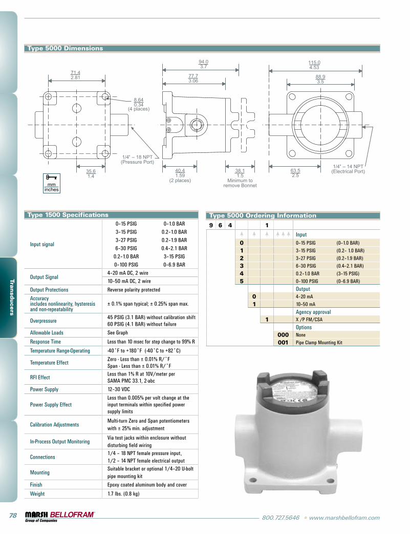
Type 1500 Specifications
input signal
0–15 psig 0–1.0 BAR
3–15 psig 0.2–1.0 BAR
3–27 psig 0.2–1.9 BAR
6–30 psig 0.4–2.1 BAR
0.2–1.0 BAR 3–15 psig
0–100 psig 0–6.9 BAR
Output signal4–20 mA DC, 2 wire
10–50 mA DC, 2 wire
Output protections Reverse polarity protected
Accuracy includes nonlinearity, hysteresis and non-repeatability
± 0.1% span typical; ± 0.25% span max.
Overpressure45 psig (3.1 BAR) without calibration shift 60 psig (4.1 BAR) without failure
Allowable loads see graph
Response Time less than 10 msec for step change to 99% R
Temperature Range-Operating -40˚F to +180˚F (-40˚C to +82˚C)
Temperature EffectZero - less than ± 0.01% R/˚F span - less than ± 0.01% R/˚F
RFi Effectless than 1% R at 10V/meter per sAMA pMC 33.1, 2-abc
power supply 12–30 VDC
power supply Effectless than 0.005% per volt change at the input terminals within specified power supply limits
Calibration AdjustmentsMulti-turn Zero and span potentiometers with ± 25% min. adjustment
in-process Output MonitoringVia test jacks within enclosure without disturbing field wiring
Connections1/4 – 18 NpT female pressure input, 1/2 – 14 NpT female electrical output
Mountingsuitable bracket or optional 1/4–20 U-bolt pipe mounting kit
Finish Epoxy coated aluminum body and cover
Weight 1.7 lbs. (0.8 kg)
Type 5000 Dimensions
Type 5000 Ordering Information
9 6 4 1
input0 0–15 psig (0–1.0 BAR)
1 3–15 psig (0.2– 1.0 BAR)
2 3–27 psig (0.2–1.9 BAR)
3 6–30 psig (0.4–2.1 BAR)
4 0.2–1.0 BAR (3–15 psig)
5 0–100 psig (0–6.9 BAR)
Output0 4–20 mA
1 10–50 mA
Agency approval1 X /p FM/CsA
Options000 None
001 pipe Clamp Mounting Kit