Embed Size (px)
Citation preview
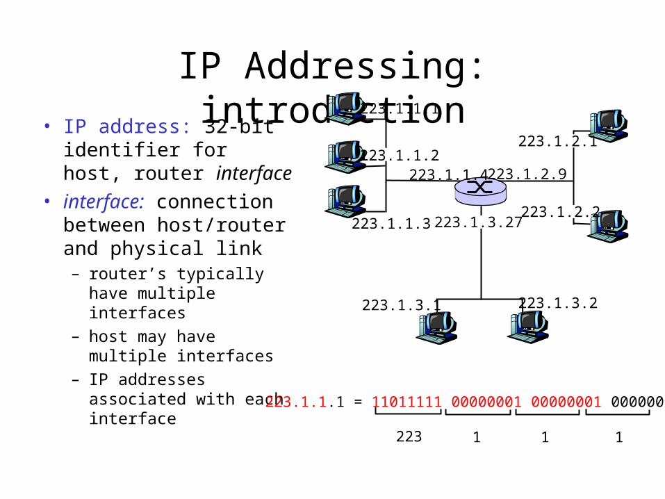
IP Addressing: introduction• IP address: 32-bit
identifier for host, router interface
• interface: connection between host/router and physical link– router’s typically have
multiple interfaces
– host may have multiple interfaces
– IP addresses associated with each interface
223.1.1.1
223.1.1.2
223.1.1.3
223.1.1.4 223.1.2.9
223.1.2.2
223.1.2.1
223.1.3.2223.1.3.1
223.1.3.27
223.1.1.1 = 11011111 00000001 00000001 00000001
223 1 11
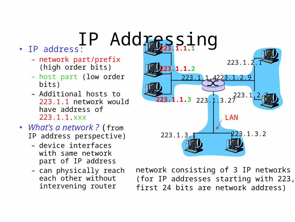
IP Addressing• IP address:
– network part/prefix (high order bits)
– host part (low order bits) – Additional hosts to 223.1.1
network would have address of 223.1.1.xxx
• What’s a network ? (from IP address perspective)– device interfaces with
same network part of IP address
– can physically reach each other without intervening router
223.1.1.1
223.1.1.2
223.1.1.3
223.1.1.4 223.1.2.9
223.1.2.2
223.1.2.1
223.1.3.2223.1.3.1
223.1.3.27
network consisting of 3 IP networks(for IP addresses starting with 223, first 24 bits are network address)
LAN
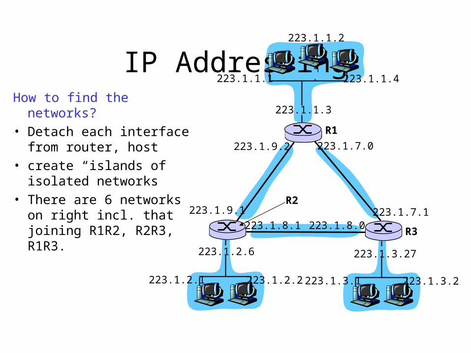
IP AddressingHow to find the networks?
• Detach each interface from router, host
• create “islands of isolated networks
• There are 6 networks on right incl. that joining R1R2, R2R3, R1R3.
223.1.1.1
223.1.1.3
223.1.1.4
223.1.2.2223.1.2.1
223.1.2.6
223.1.3.2223.1.3.1
223.1.3.27
223.1.1.2
223.1.7.0
223.1.7.1223.1.8.0223.1.8.1
223.1.9.1
223.1.9.2
R1
R3
R2
IP Addresses
0network host
1110 multicast address
A
D
class1.0.0.0 to127.255.255.255
10 network hostB 128.0.0.0 to191.255.255.255
110 network hostC 192.0.0.0 to223.255.255.255
224.0.0.0 to239.255.255.255
32 bits
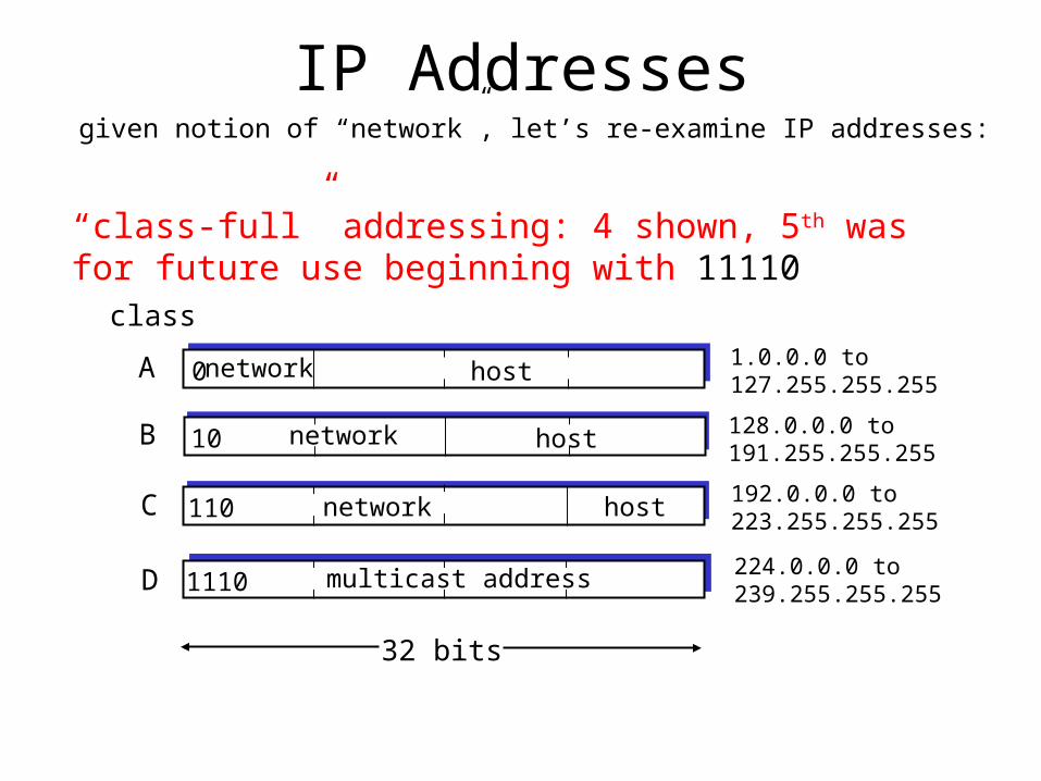
given notion of “network”, let’s re-examine IP addresses:
“class-full” addressing: 4 shown, 5th was for future use beginning with 11110
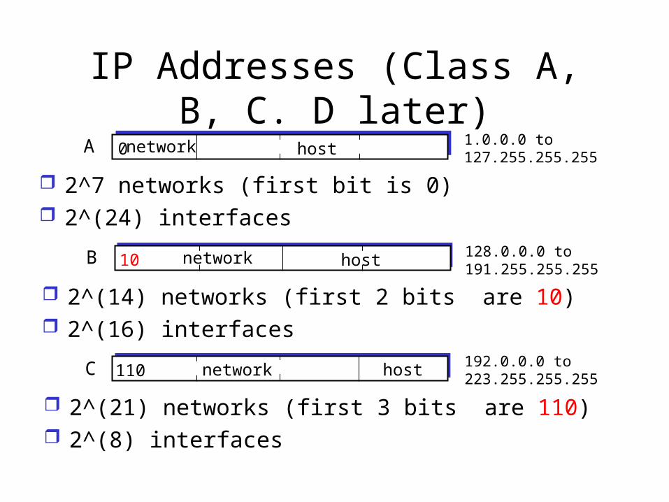
IP Addresses (Class A, B, C. D later)
0network hostA 1.0.0.0 to127.255.255.255
2^7 networks (first bit is 0) 2^(24) interfaces
10 network hostB 128.0.0.0 to191.255.255.255
2^(14) networks (first 2 bits are 10) 2^(16) interfaces
110 network hostC 192.0.0.0 to223.255.255.255
2^(21) networks (first 3 bits are 110) 2^(8) interfaces
Classful addressing Class A, B, C networks require 1, 2 and 3 bytes for
the network portion. E.g., Class C networks can accommodate only
2^8-2 = 254 hosts (2 are reserved). Small for most medium to large organizations.
However Class B supports 65,634 hosts – too large. An organization with 2000 hosts ended up with class B addressing – address space was ill used.
Therefore in 1993, Classless Interdomain Routing (CIDR) was introduced.
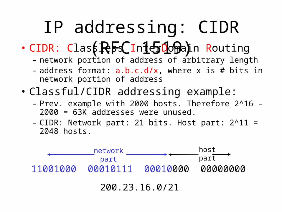
IP addressing: CIDR (RFC 1519)• CIDR: Classless InterDomain Routing
– network portion of address of arbitrary length– address format: a.b.c.d/x, where x is # bits in network portion
of address
• Classful/CIDR addressing example: – Prev. example with 2000 hosts. Therefore 2^16 – 2000 = 63K
addresses were unused.– CIDR: Network part: 21 bits. Host part: 2^11 = 2048 hosts.
11001000 00010111 00010000 00000000
networkpart
hostpart
200.23.16.0/21
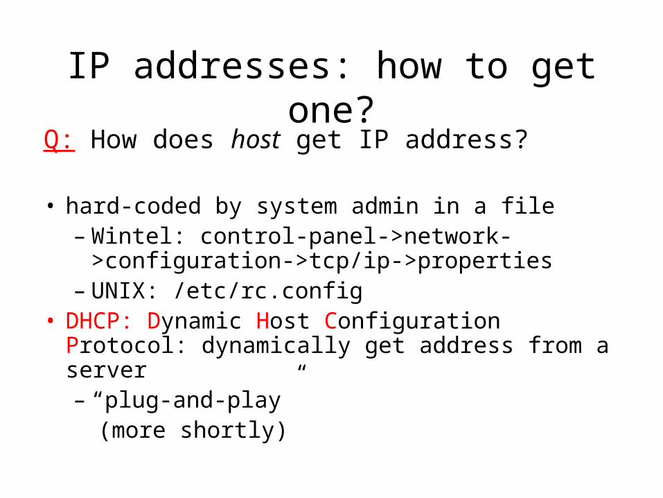
IP addresses: how to get one?Q: How does host get IP address?
• hard-coded by system admin in a file– Wintel: control-panel->network->configuration-
>tcp/ip->properties– UNIX: /etc/rc.config
• DHCP: Dynamic Host Configuration Protocol: dynamically get address from a server– “plug-and-play”
(more shortly)
IP addresses: how to get one?
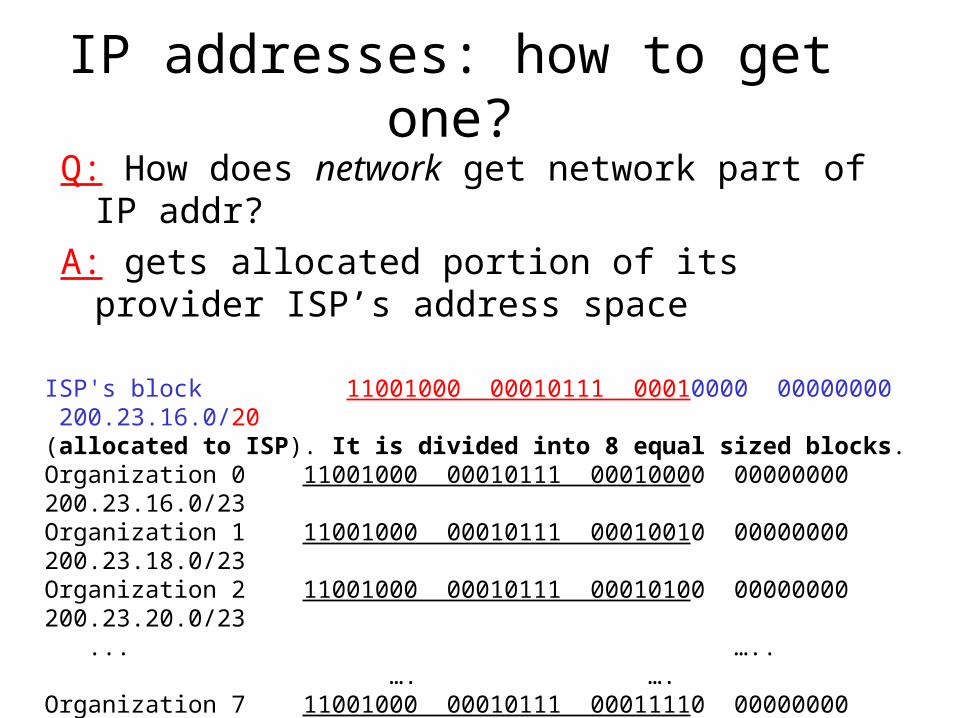
Q: How does network get network part of IP addr?
A: gets allocated portion of its provider ISP’s address space
ISP's block 11001000 00010111 00010000 00000000 200.23.16.0/20 (allocated to ISP). It is divided into 8 equal sized blocks.Organization 0 11001000 00010111 00010000 00000000 200.23.16.0/23 Organization 1 11001000 00010111 00010010 00000000 200.23.18.0/23 Organization 2 11001000 00010111 00010100 00000000 200.23.20.0/23 ... ….. …. ….
Organization 7 11001000 00010111 00011110 00000000 200.23.30.0/23
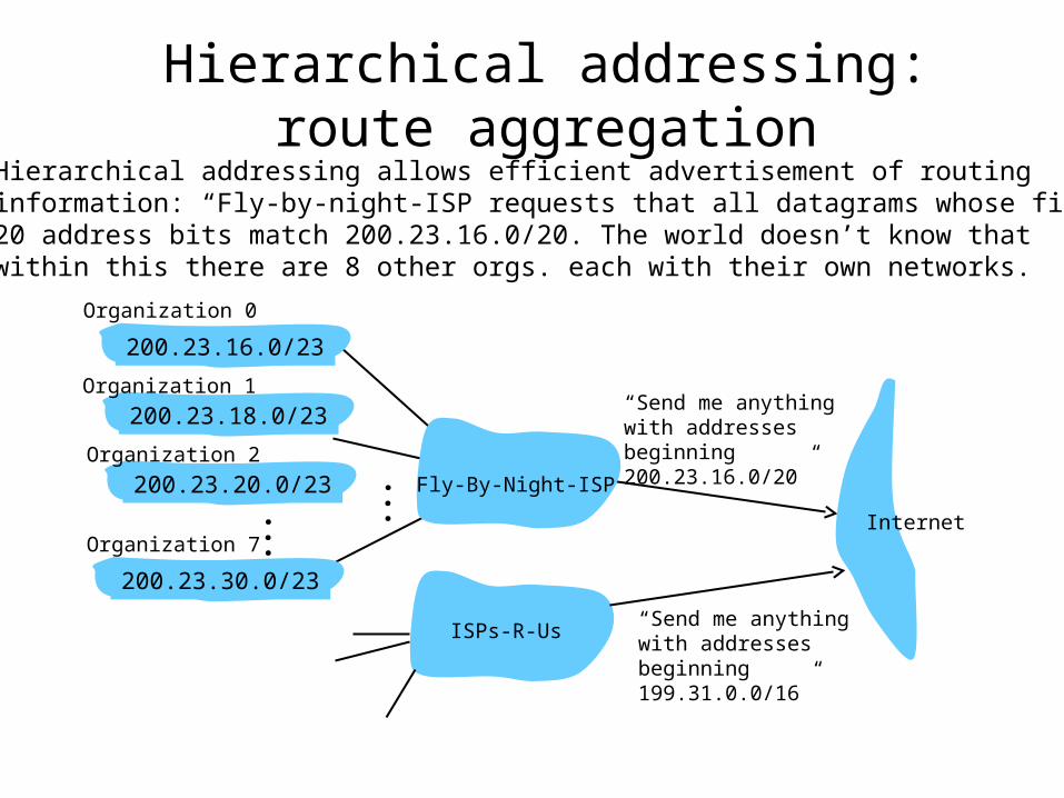
Hierarchical addressing: route aggregation
“Send me anythingwith addresses beginning 200.23.16.0/20”
200.23.16.0/23
200.23.18.0/23
200.23.30.0/23
Fly-By-Night-ISP
Organization 0
Organization 7Internet
Organization 1
ISPs-R-Us“Send me anythingwith addresses beginning 199.31.0.0/16”
200.23.20.0/23Organization 2
...
...
Hierarchical addressing allows efficient advertisement of routing information: “Fly-by-night-ISP requests that all datagrams whose first20 address bits match 200.23.16.0/20. The world doesn’t know thatwithin this there are 8 other orgs. each with their own networks.
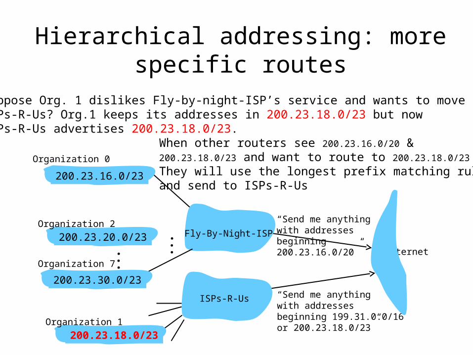
Hierarchical addressing: more specific routes
Suppose Org. 1 dislikes Fly-by-night-ISP’s service and wants to move to ISPs-R-Us? Org.1 keeps its addresses in 200.23.18.0/23 but now ISPs-R-Us advertises 200.23.18.0/23.
Organization 0
“Send me anythingwith addresses beginning 200.23.16.0/20” Internet
“Send me anythingwith addresses beginning 199.31.0.0/16or 200.23.18.0/23”
Fly-By-Night-ISP
ISPs-R-Us
200.23.16.0/23
200.23.18.0/23
200.23.30.0/23
Organization 7
Organization 1
200.23.20.0/23Organization 2
...
...
When other routers see 200.23.16.0/20 & 200.23.18.0/23 and want to route to 200.23.18.0/23 They will use the longest prefix matching rule and send to ISPs-R-Us
IP addressing: the last word...
Q: How does an ISP get block of addresses?
A: ICANN: Internet Corporation for Assigned
Names and Numbers (guidelines in RFC 2050)– allocates addresses– manages DNS– assigns domain names, resolves disputes
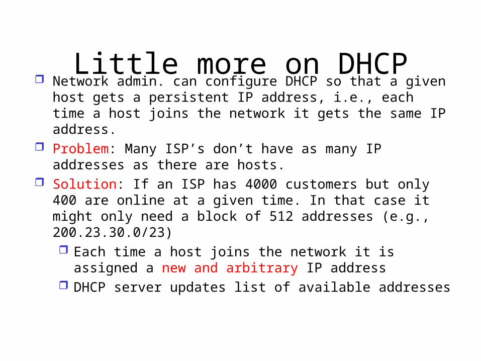
Little more on DHCP Network admin. can configure DHCP so that a given host
gets a persistent IP address, i.e., each time a host joins the network it gets the same IP address.
Problem: Many ISP’s don’t have as many IP addresses as there are hosts.
Solution: If an ISP has 4000 customers but only 400 are online at a given time. In that case it might only need a block of 512 addresses (e.g., 200.23.30.0/23) Each time a host joins the network it is assigned a new
and arbitrary IP address DHCP server updates list of available addresses
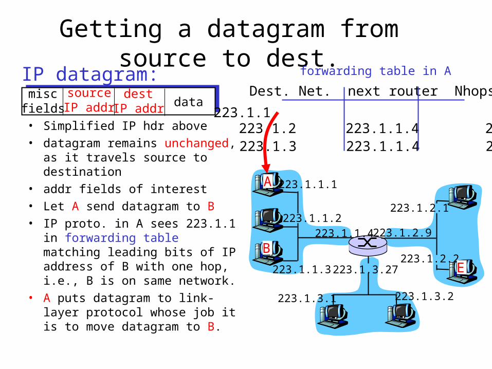
Getting a datagram from source to dest.IP datagram:
223.1.1.1
223.1.1.2
223.1.1.3
223.1.1.4 223.1.2.9
223.1.2.2
223.1.2.1
223.1.3.2223.1.3.1
223.1.3.27
A
BE
miscfields
sourceIP addr
destIP addr data
• Simplified IP hdr above
• datagram remains unchanged, as it travels source to destination
• addr fields of interest
• Let A send datagram to B
• IP proto. in A sees 223.1.1 in forwarding table matching leading bits of IP address of B with one hop, i.e., B is on same network.
• A puts datagram to link-layer protocol whose job it is to move datagram to B.
Dest. Net. next router Nhops
223.1.1 1223.1.2 223.1.1.4 2223.1.3 223.1.1.4 2
forwarding table in A

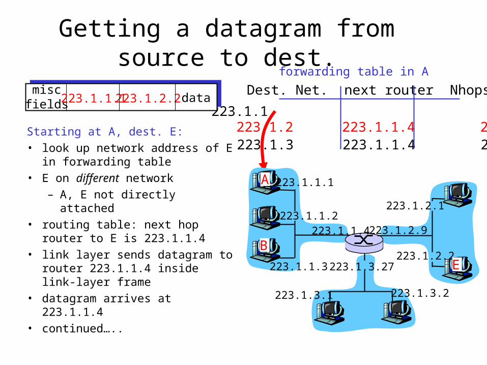
Getting a datagram from source to dest.
Dest. Net. next router Nhops
223.1.1 1223.1.2 223.1.1.4 2223.1.3 223.1.1.4 2
Starting at A, dest. E:
• look up network address of E in forwarding table
• E on different network
– A, E not directly attached
• routing table: next hop router to E is 223.1.1.4
• link layer sends datagram to router 223.1.1.4 inside link-layer frame
• datagram arrives at 223.1.1.4
• continued…..
miscfields223.1.1.1223.1.2.2 data
223.1.1.1
223.1.1.2
223.1.1.3
223.1.1.4 223.1.2.9
223.1.2.2
223.1.2.1
223.1.3.2223.1.3.1
223.1.3.27
A
BE
forwarding table in A
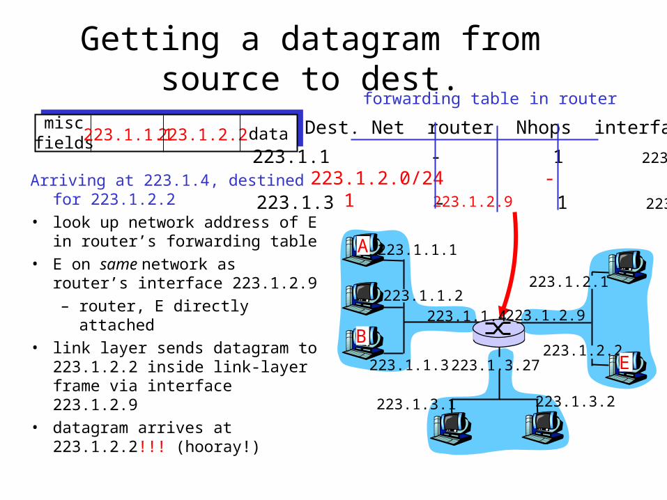
Getting a datagram from source to dest.
Arriving at 223.1.4, destined for 223.1.2.2
• look up network address of E in router’s forwarding table
• E on same network as router’s interface 223.1.2.9 – router, E directly attached
• link layer sends datagram to 223.1.2.2 inside link-layer frame via interface 223.1.2.9
• datagram arrives at 223.1.2.2!!! (hooray!)
miscfields223.1.1.1223.1.2.2 data Dest. Net router Nhops interface
223.1.1 - 1 223.1.1.4 223.1.2.0/24 - 1 223.1.2.9
223.1.3 - 1 223.1.3.27
223.1.1.1
223.1.1.2
223.1.1.3
223.1.1.4 223.1.2.9
223.1.2.2
223.1.2.1
223.1.3.2223.1.3.1
223.1.3.27
A
BE
forwarding table in router
More on forwarding tables• Forwarding tables in routers are central
• How are forwarding tables configured and maintained for large networks with multiple paths?– These tables must allow good paths
• As it turns out, routing algorithms have the role of configuring and maintaining these tables.
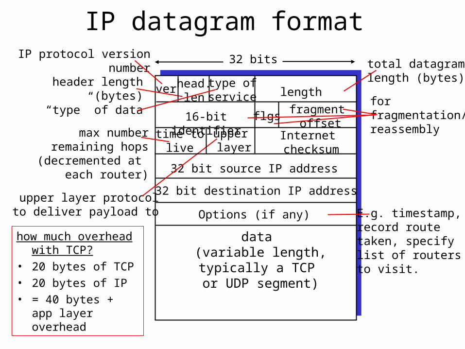
IP datagram format
ver length
32 bits
data (variable length,typically a TCP
or UDP segment)
16-bit identifier
Internet checksum
time tolive
32 bit source IP address
IP protocol versionnumber
header length (bytes)
max numberremaining hops
(decremented at each router)
forfragmentation/reassembly
total datagramlength (bytes)
upper layer protocolto deliver payload to
head.len
type ofservice
“type” of data flgsfragment
offsetupper layer
32 bit destination IP address
Options (if any) E.g. timestamp,record routetaken, specifylist of routers to visit.
how much overhead with TCP?
• 20 bytes of TCP
• 20 bytes of IP
• = 40 bytes + app layer overhead
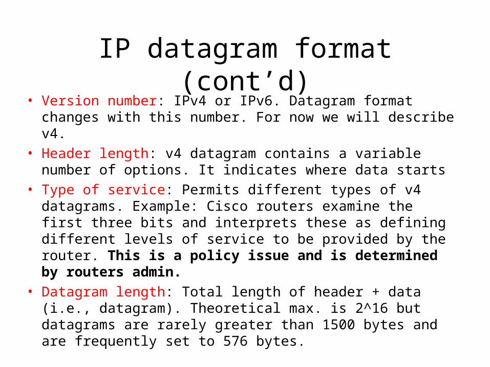
IP datagram format (cont’d)• Version number: IPv4 or IPv6. Datagram format changes with
this number. For now we will describe v4.
• Header length: v4 datagram contains a variable number of options. It indicates where data starts
• Type of service: Permits different types of v4 datagrams. Example: Cisco routers examine the first three bits and interprets these as defining different levels of service to be provided by the router. This is a policy issue and is determined by routers admin.
• Datagram length: Total length of header + data (i.e., datagram). Theoretical max. is 2^16 but datagrams are rarely greater than 1500 bytes and are frequently set to 576 bytes.

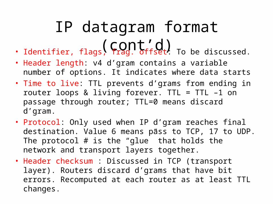
IP datagram format (cont’d)• Identifier, flags, frag. offset: To be discussed.
• Header length: v4 d’gram contains a variable number of options. It indicates where data starts
• Time to live: TTL prevents d’grams from ending in router loops & living forever. TTL = TTL –1 on passage through router; TTL=0 means discard d’gram.
• Protocol: Only used when IP d’gram reaches final destination. Value 6 means pass to TCP, 17 to UDP. The protocol # is the “glue” that holds the network and transport layers together.
• Header checksum : Discussed in TCP (transport layer). Routers discard d’grams that have bit errors. Recomputed at each router as at least TTL changes.
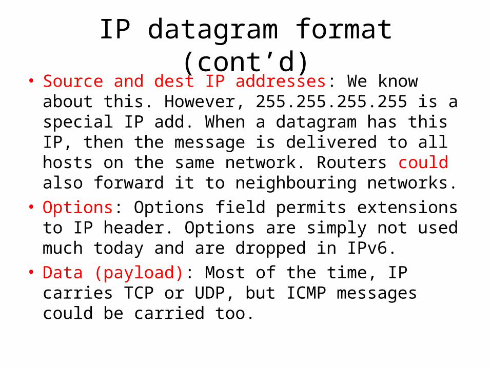
IP datagram format (cont’d)• Source and dest IP addresses: We know about this.
However, 255.255.255.255 is a special IP add. When a datagram has this IP, then the message is delivered to all hosts on the same network. Routers could also forward it to neighbouring networks.
• Options: Options field permits extensions to IP header. Options are simply not used much today and are dropped in IPv6.
• Data (payload): Most of the time, IP carries TCP or UDP, but ICMP messages could be carried too.
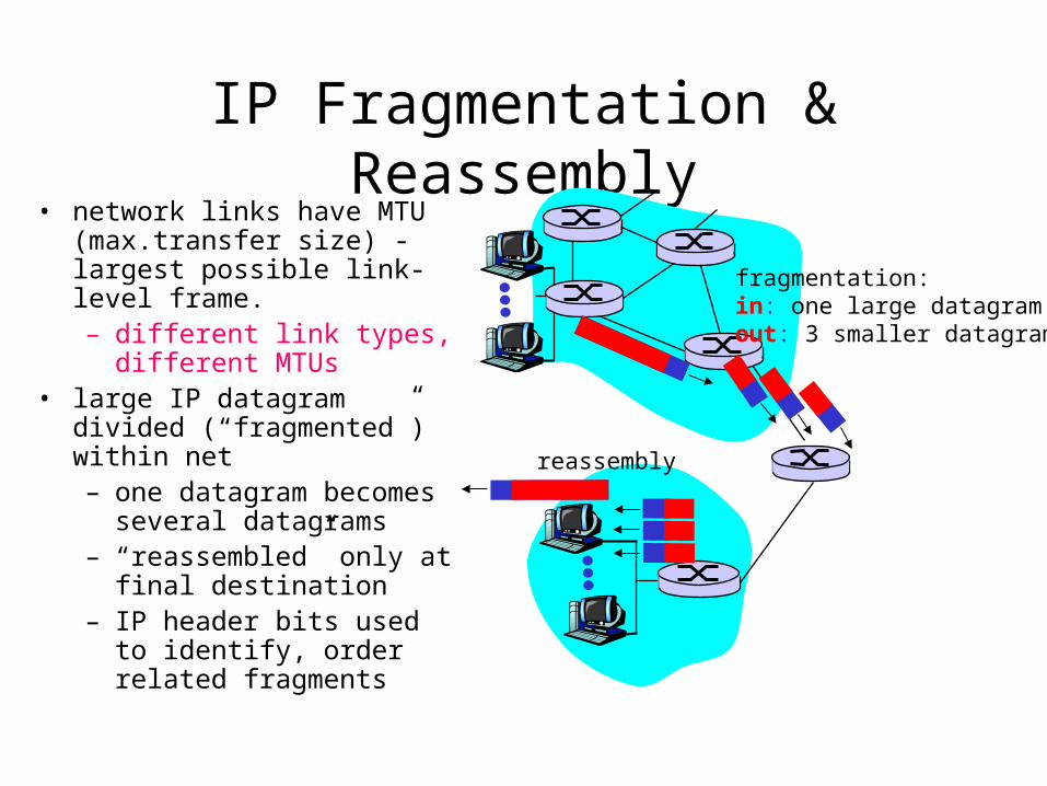
IP Fragmentation & Reassembly• network links have MTU
(max.transfer size) - largest possible link-level frame.– different link types,
different MTUs • large IP datagram divided
(“fragmented”) within net– one datagram becomes
several datagrams– “reassembled” only at final
destination– IP header bits used to
identify, order related fragments
fragmentation: in: one large datagramout: 3 smaller datagrams
reassembly
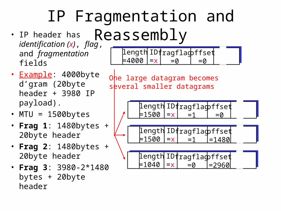
IP Fragmentation and Reassembly
ID=x
offset=0
fragflag=0
length=4000
ID=x
offset=0
fragflag=1
length=1500
ID=x
offset=1480
fragflag=1
length=1500
ID=x
offset=2960
fragflag=0
length=1040
One large datagram becomesseveral smaller datagrams
• IP header has identification (x), flag, and fragmentation fields
• Example: 4000byte d’gram (20byte header + 3980 IP payload).
• MTU = 1500bytes
• Frag 1: 1480bytes + 20byte header
• Frag 2: 1480bytes + 20byte header
• Frag 3: 3980-2*1480 bytes + 20byte header
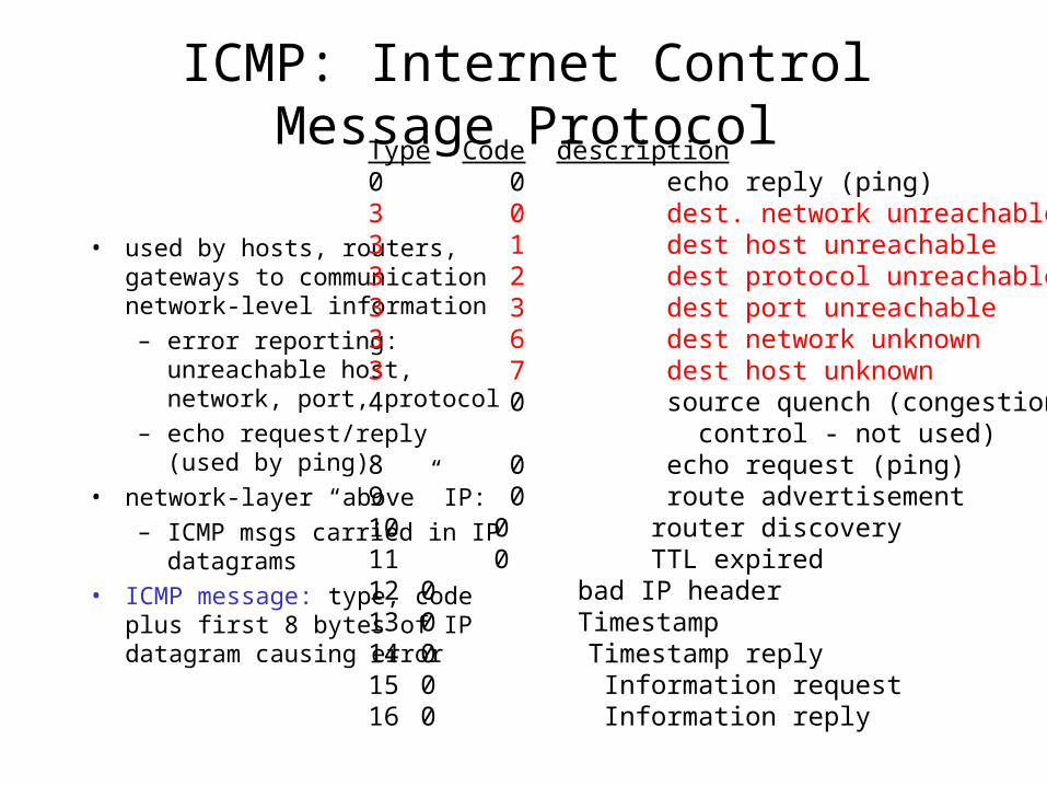
ICMP: Internet Control Message Protocol
• used by hosts, routers, gateways to communication network-level information
– error reporting: unreachable host, network, port, protocol
– echo request/reply (used by ping)
• network-layer “above” IP:
– ICMP msgs carried in IP datagrams
• ICMP message: type, code plus first 8 bytes of IP datagram causing error
Type Code description0 0 echo reply (ping)3 0 dest. network unreachable3 1 dest host unreachable3 2 dest protocol unreachable3 3 dest port unreachable3 6 dest network unknown3 7 dest host unknown4 0 source quench (congestion control - not used)8 0 echo request (ping)9 0 route advertisement10 0 router discovery11 0 TTL expired12 0 bad IP header13 0 Timestamp14 0 Timestamp reply15 0 Information request16 0 Information reply
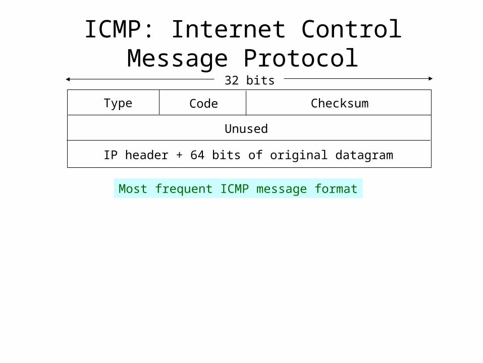
ICMP: Internet Control Message Protocol32 bits
Type Code Checksum
Unused
IP header + 64 bits of original datagram
Most frequent ICMP message format
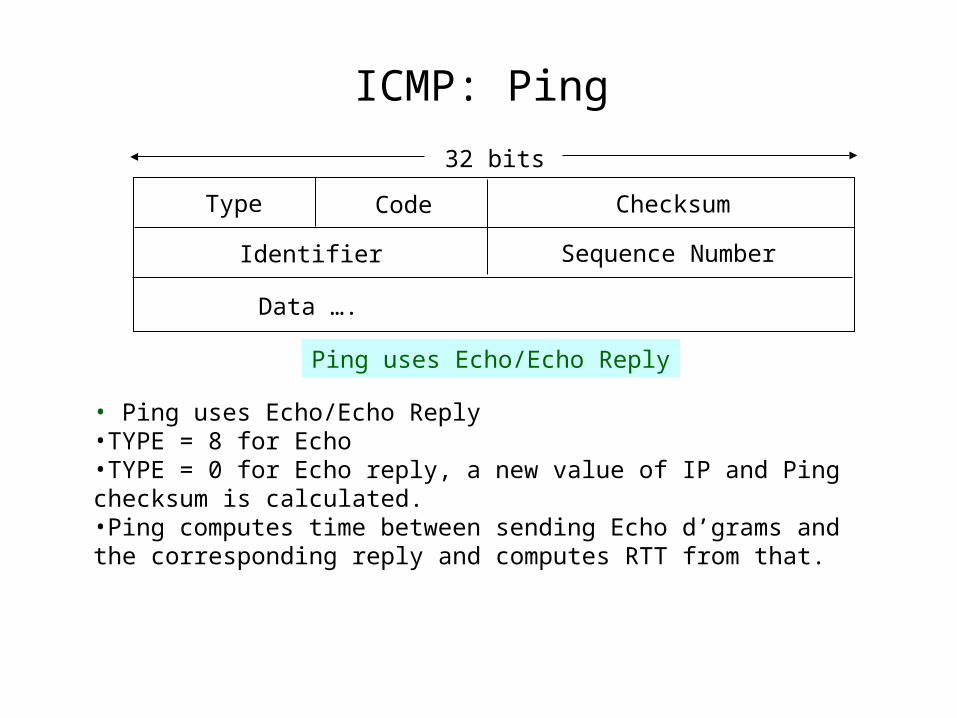
ICMP: Ping
32 bits
Type Code Checksum
Data ….
Ping uses Echo/Echo Reply
Identifier Sequence Number
• Ping uses Echo/Echo Reply•TYPE = 8 for Echo•TYPE = 0 for Echo reply, a new value of IP and Ping checksum is calculated.•Ping computes time between sending Echo d’grams and the corresponding reply and computes RTT from that.
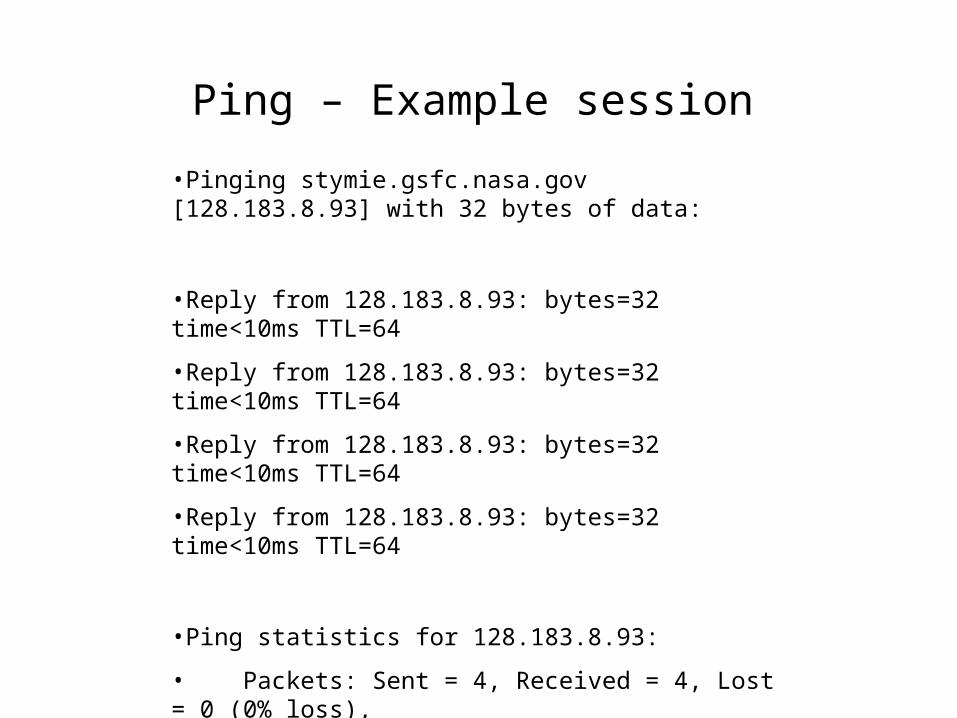
•Pinging stymie.gsfc.nasa.gov [128.183.8.93] with 32 bytes of data:
•Reply from 128.183.8.93: bytes=32 time<10ms TTL=64
•Reply from 128.183.8.93: bytes=32 time<10ms TTL=64
•Reply from 128.183.8.93: bytes=32 time<10ms TTL=64
•Reply from 128.183.8.93: bytes=32 time<10ms TTL=64
•Ping statistics for 128.183.8.93:
• Packets: Sent = 4, Received = 4, Lost = 0 (0% loss),
•Approximate round trip times in milli-seconds:
• Minimum = 0ms, Maximum = 0ms, Average = 0ms
Ping – Example session
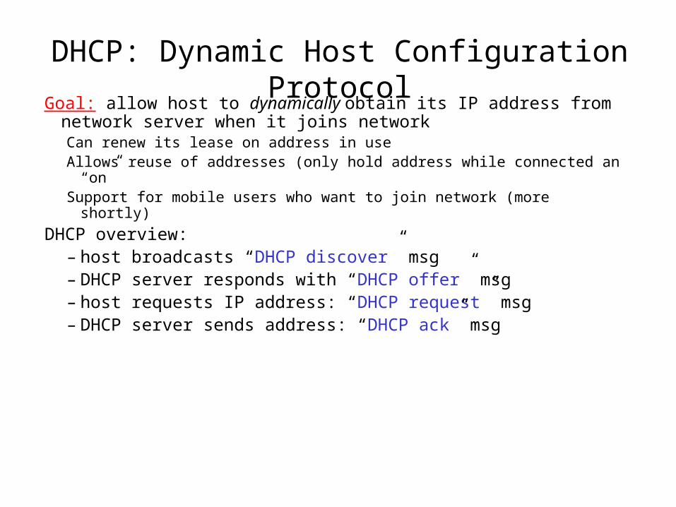
DHCP: Dynamic Host Configuration ProtocolGoal: allow host to dynamically obtain its IP address from network
server when it joins networkCan renew its lease on address in useAllows reuse of addresses (only hold address while connected an “on”Support for mobile users who want to join network (more shortly)
DHCP overview:– host broadcasts “DHCP discover” msg– DHCP server responds with “DHCP offer” msg– host requests IP address: “DHCP request” msg– DHCP server sends address: “DHCP ack” msg
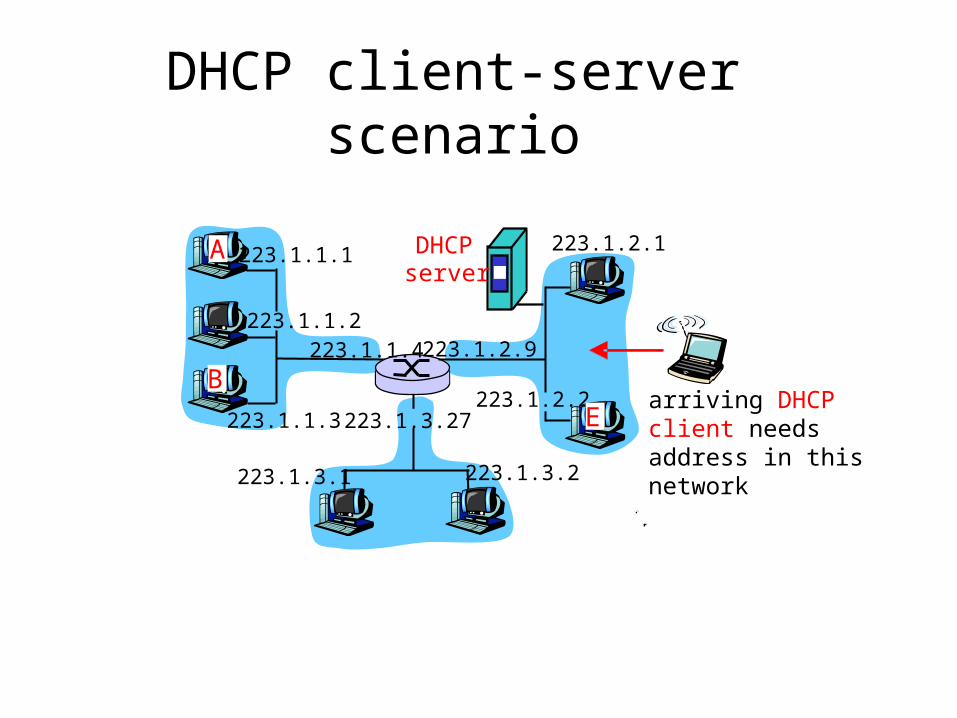
DHCP client-server scenario
223.1.1.1
223.1.1.2
223.1.1.3
223.1.1.4 223.1.2.9
223.1.2.2
223.1.2.1
223.1.3.2223.1.3.1
223.1.3.27
A
BE
DHCP server
arriving DHCP client needsaddress in thisnetwork
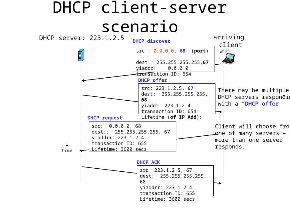
DHCP client-server scenarioDHCP server: 223.1.2.5 arriving
client
time
DHCP discover
src : 0.0.0.0, 68 (port) dest.: 255.255.255.255,67yiaddr: 0.0.0.0transaction ID: 654
DHCP offer
src: 223.1.2.5, 67 dest: 255.255.255.255, 68yiaddr: 223.1.2.4transaction ID: 654Lifetime (of IP Add): 3600 secs
DHCP request
src: 0.0.0.0, 68 dest:: 255.255.255.255, 67yiaddrr: 223.1.2.4transaction ID: 655Lifetime: 3600 secs
DHCP ACK
src: 223.1.2.5, 67 dest: 255.255.255.255, 68yiaddrr: 223.1.2.4transaction ID: 655Lifetime: 3600 secs
There may be multipleDHCP servers respondingwith a “DHCP offer”
Client will choose fromone of many servers – ifmore than one serverresponds.
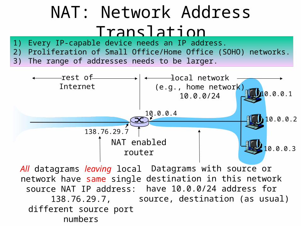
NAT: Network Address Translation
10.0.0.1
10.0.0.2
10.0.0.3
10.0.0.4
138.76.29.7
local network(e.g., home network)
10.0.0/24
rest ofInternet
Datagrams with source or destination in this networkhave 10.0.0/24 address for
source, destination (as usual)
All datagrams leaving localnetwork have same single source
NAT IP address: 138.76.29.7,different source port numbers
1) Every IP-capable device needs an IP address.2) Proliferation of Small Office/Home Office (SOHO) networks.3) The range of addresses needs to be larger.
NAT enabledrouter
NAT: Network Address Translation
• Motivation: local network uses just one IP address as far as outside word is concerned:– no need to be allocated range of addresses from ISP:
- just one IP address is used for all devices– can change addresses of devices in local network
without notifying outside world– can change ISP without changing addresses of
devices in local network– devices inside local net not explicitly addressable,
visible by outside world (a security plus).
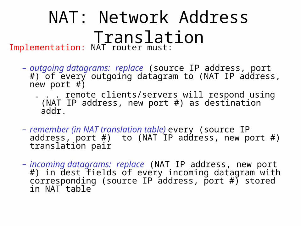
NAT: Network Address TranslationImplementation: NAT router must:
– outgoing datagrams: replace (source IP address, port #) of every outgoing datagram to (NAT IP address, new port #)
. . . remote clients/servers will respond using (NAT IP address, new port #) as destination addr.
– remember (in NAT translation table) every (source IP address, port #) to (NAT IP address, new port #) translation pair
– incoming datagrams: replace (NAT IP address, new port #) in dest fields of every incoming datagram with corresponding (source IP address, port #) stored in NAT table
NAT: Network Address Translation
10.0.0.1
10.0.0.2
10.0.0.3
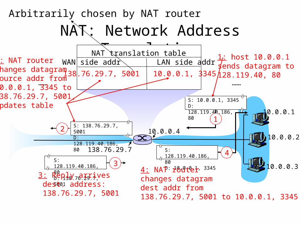
S: 10.0.0.1, 3345D: 128.119.40.186, 80
1
10.0.0.4
138.76.29.7
1: host 10.0.0.1 sends datagram to 128.119.40, 80
NAT translation tableWAN side addr LAN side addr
138.76.29.7, 5001 10.0.0.1, 3345…… ……
S: 128.119.40.186, 80 D: 10.0.0.1, 3345
4
S: 138.76.29.7, 5001D: 128.119.40.186, 80
2
2: NAT routerchanges datagramsource addr from10.0.0.1, 3345 to138.76.29.7, 5001,updates table
S: 128.119.40.186, 80 D: 138.76.29.7, 5001
3
3: Reply arrives dest. address: 138.76.29.7, 5001
4: NAT routerchanges datagramdest addr from138.76.29.7, 5001 to 10.0.0.1, 3345
Arbitrarily chosen by NAT router
NAT: Network Address Translation
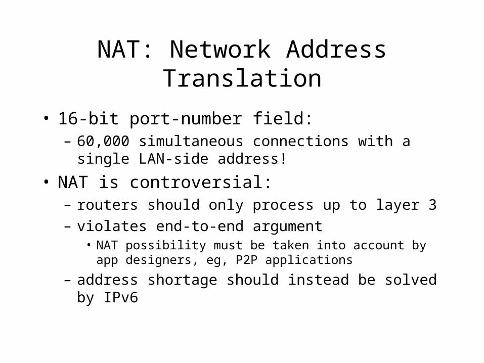
• 16-bit port-number field: – 60,000 simultaneous connections with a single LAN-
side address!
• NAT is controversial:– routers should only process up to layer 3
– violates end-to-end argument• NAT possibility must be taken into account by app designers,
eg, P2P applications
– address shortage should instead be solved by IPv6
Chapter 4 roadmap4.1 Introduction and Network Service Models4.2 Routing Principles4.3 Hierarchical Routing4.4 The Internet (IP) Protocol4.5 Routing in the Internet
– 4.5.1 Intra-AS routing: RIP and OSPF– 4.5.2 Inter-AS routing: BGP
4.6 What’s Inside a Router?4.7 IPv64.8 Multicast Routing4.9 Mobility
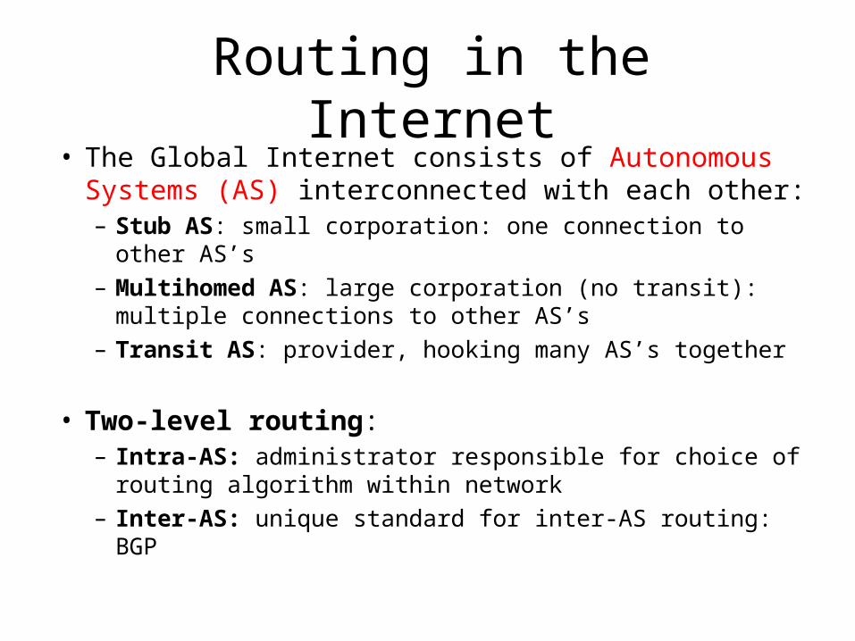
Routing in the Internet• The Global Internet consists of Autonomous Systems
(AS) interconnected with each other:– Stub AS: small corporation: one connection to other AS’s
– Multihomed AS: large corporation (no transit): multiple connections to other AS’s
– Transit AS: provider, hooking many AS’s together
• Two-level routing: – Intra-AS: administrator responsible for choice of routing
algorithm within network
– Inter-AS: unique standard for inter-AS routing: BGP
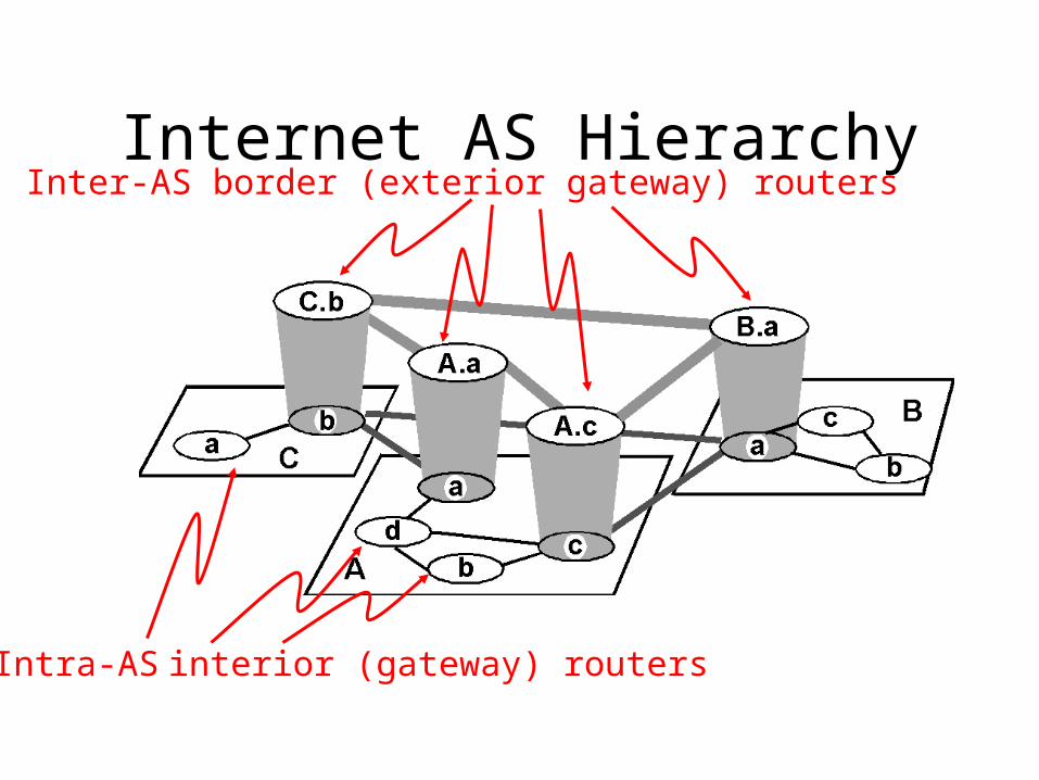
Internet AS HierarchyInter-AS border (exterior gateway) routers
Intra-AS interior (gateway) routers
Intra-AS Routing
• Also known as Interior Gateway Protocols (IGP)• Most common Intra-AS routing protocols:
– RIP: Routing Information Protocol
– OSPF: Open Shortest Path First
– IGRP: Interior Gateway Routing Protocol (Cisco proprietary)
RIP ( Routing Information Protocol)
• Distance vector algorithm• Included in BSD-UNIX Distribution in 1982• Distance metric: # of hops (max = 15 hops)
– Can you guess why?
• Distance vectors: exchanged among neighbors every 30 sec via Response Message (also called advertisement)
• Each advertisement: list of up to 25 destination nets within AS
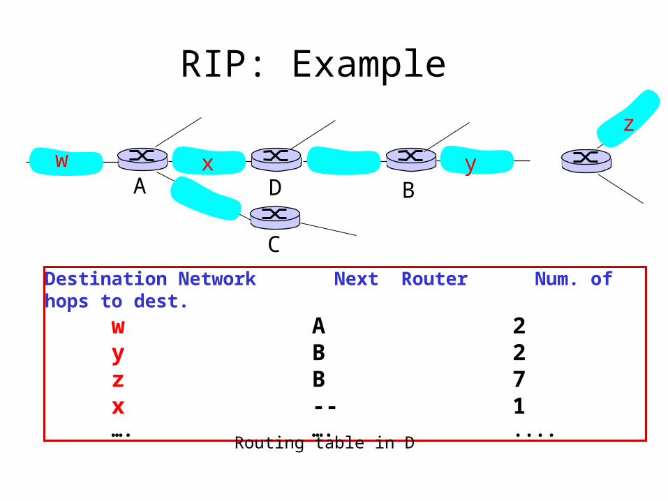
RIP: Example
Destination Network Next Router Num. of hops to dest. w A 2
y B 2 z B 7
x -- 1…. …. ....
w x y
z
A
C
D B
Routing table in D
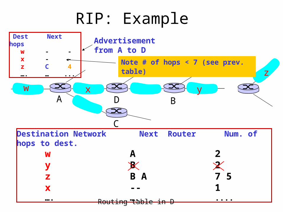
RIP: Example
Destination Network Next Router Num. of hops to dest. w A 2
y B 2 z B A 7 5
x -- 1…. …. ....Routing table in D
w x y
z
A
C
D B
Dest Next hops w - - x - - z C 4 …. … ...
Advertisementfrom A to D
Note # of hops < 7 (see prev. table)
RIP: Link Failure and Recovery If no advertisement heard after 180 sec -->
neighbor/link declared dead– routes via neighbor invalidated– new advertisements sent to neighbors– neighbors in turn send out new advertisements (if
tables changed)– link failure info quickly propagates to entire net– poison reverse used to prevent ping-pong loops
(infinite distance = 16 hops)
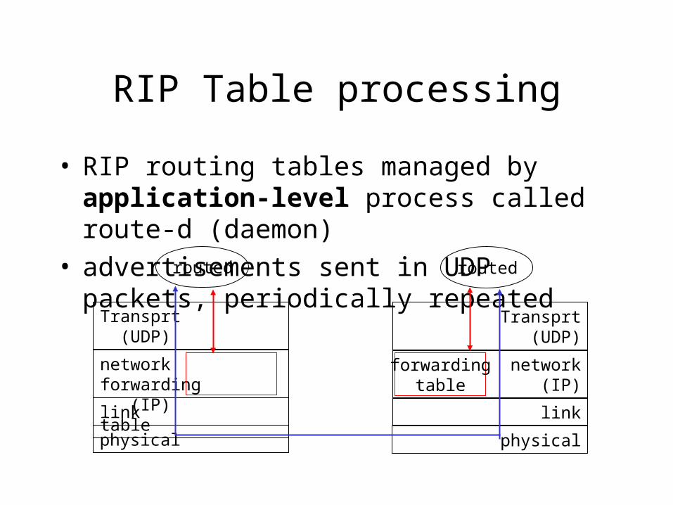
RIP Table processing
• RIP routing tables managed by application-level process called route-d (daemon)
• advertisements sent in UDP packets, periodically repeated
physical
link
network forwarding (IP) table
Transprt (UDP)
routed
physical
link
network (IP)
Transprt (UDP)
routed
forwardingtable
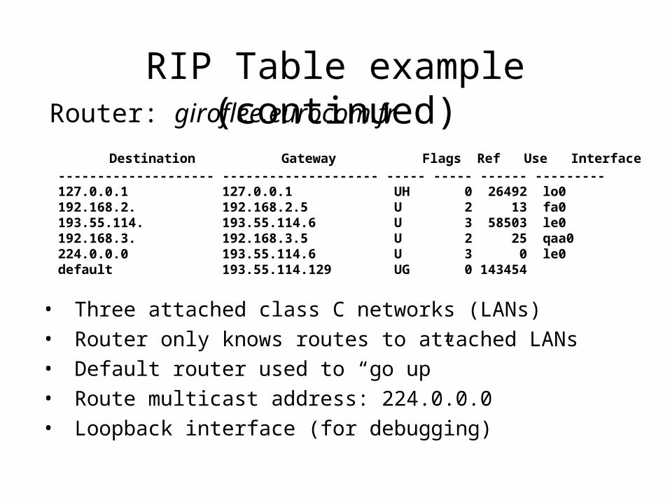
RIP Table example (continued)Router: giroflee.eurocom.fr
• Three attached class C networks (LANs)• Router only knows routes to attached LANs• Default router used to “go up”• Route multicast address: 224.0.0.0• Loopback interface (for debugging)
Destination Gateway Flags Ref Use Interface -------------------- -------------------- ----- ----- ------ --------- 127.0.0.1 127.0.0.1 UH 0 26492 lo0 192.168.2. 192.168.2.5 U 2 13 fa0 193.55.114. 193.55.114.6 U 3 58503 le0 192.168.3. 192.168.3.5 U 2 25 qaa0 224.0.0.0 193.55.114.6 U 3 0 le0 default 193.55.114.129 UG 0 143454
OSPF (Open Shortest Path First)• “open”: publicly available• Uses Link State algorithm
– LS packet dissemination– Topology map at each node– Route computation using Dijkstra’s algorithm
• OSPF advertisement carries one entry per neighbor router
• Advertisements disseminated to entire AS (via flooding)– Carried in OSPF messages directly over IP (rather than
TCP or UDP
OSPF “advanced” features (not in RIP)
• Security: all OSPF messages authenticated (to prevent malicious intrusion)
• Multiple same-cost paths allowed (only one path in RIP)
• For each link, multiple cost metrics for different TOS (e.g., satellite link cost set “low” for best effort; high for real time)
• Integrated uni- and multicast support: – Multicast OSPF (MOSPF) uses same topology
data base as OSPF• Hierarchical OSPF in large domains.
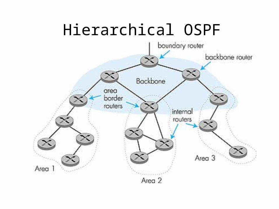
Hierarchical OSPF
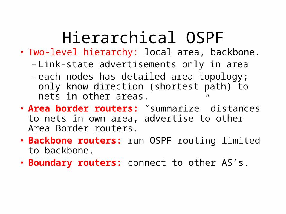
Hierarchical OSPF• Two-level hierarchy: local area, backbone.
– Link-state advertisements only in area – each nodes has detailed area topology; only know
direction (shortest path) to nets in other areas.• Area border routers: “summarize” distances to nets
in own area, advertise to other Area Border routers.• Backbone routers: run OSPF routing limited to
backbone.• Boundary routers: connect to other AS’s.
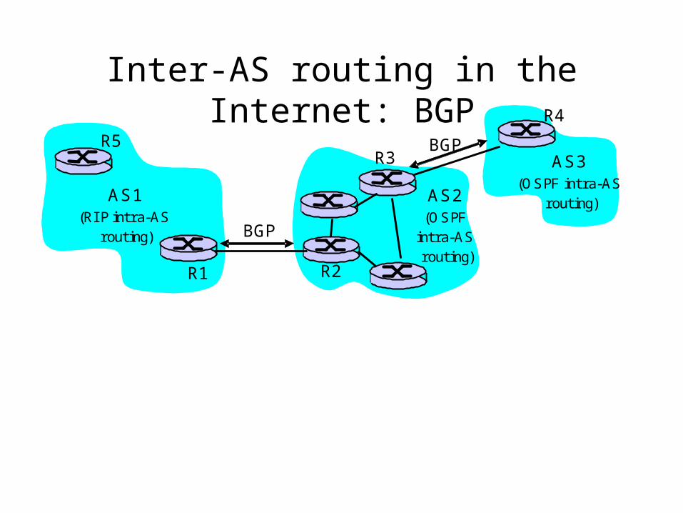
Inter-AS routing in the Internet: BGP
Figure 4.5.2-new2: BGP use for inter-domain routing
AS2 (OSPF
intra-AS routing)
AS1 (RI P intra-AS
routing) BGP
AS3 (OSPF intra-AS
routing)
BGP
R1 R2
R3
R4
R5
Internet inter-AS routing: BGP
• BGP (Border Gateway Protocol): the de facto standard
• Path Vector protocol:
– similar to Distance Vector protocol
– each Border Gateway broadcast to neighbors (peers) entire path (i.e., sequence of AS’s) to destination
– BGP routes to networks (ASs), not individual hosts– E.g., Gateway X may send its path to dest. Z:
Path (X,Z) = X,Y1,Y2,Y3,…,Z
Internet inter-AS routing: BGPSuppose: gateway X send its path to peer gateway W• W may or may not select path offered by X
– cost, policy (don’t route via competitors AS), loop prevention reasons.
• If W selects path advertised by X, then:Path (W,Z) = w, Path (X,Z)
• Note: X can control incoming traffic by controlling it route advertisements to peers:– e.g., don’t want to route traffic to Z -> don’t advertise any routes to Z
BGP: controlling who routes to you
Figure 4.5-BGPnew: a simple BGP scenario
A
B
C
W X
Y
legend:
customer network:
provider network
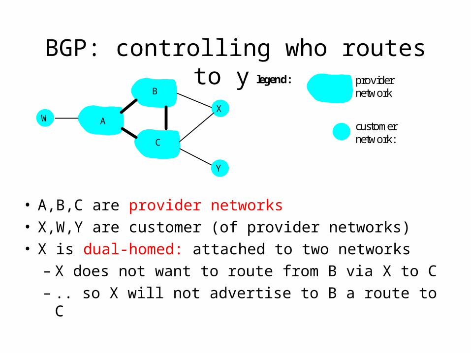
• A,B,C are provider networks• X,W,Y are customer (of provider networks)• X is dual-homed: attached to two networks
– X does not want to route from B via X to C– .. so X will not advertise to B a route to C
BGP: controlling who routes to you
Figure 4.5-BGPnew: a simple BGP scenario
A
B
C
W X
Y
legend:
customer network:
provider network
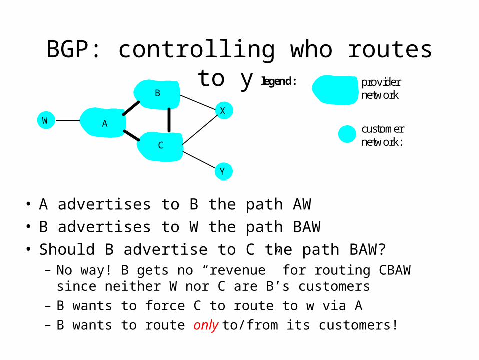
• A advertises to B the path AW • B advertises to W the path BAW • Should B advertise to C the path BAW?
– No way! B gets no “revenue” for routing CBAW since neither W nor C are B’s customers
– B wants to force C to route to w via A
– B wants to route only to/from its customers!
BGP operation
Q: What does a BGP router do?• Receiving and filtering route advertisements from
directly attached neighbor(s). • Route selection.
– To route to destination X, which path )of several advertised) will be taken?
• Sending route advertisements to neighbors.
BGP messages• BGP messages exchanged using TCP.• BGP messages:
– OPEN: opens TCP connection to peer and authenticates sender
– UPDATE: advertises new path (or withdraws old)– KEEPALIVE keeps connection alive in absence of
UPDATES; also ACKs OPEN request– NOTIFICATION: reports errors in previous msg;
also used to close connection
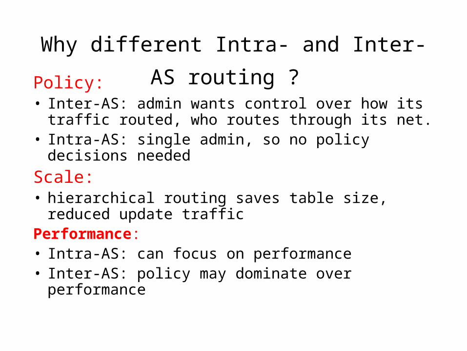
Why different Intra- and Inter-AS routing ? Policy: • Inter-AS: admin wants control over how its traffic
routed, who routes through its net. • Intra-AS: single admin, so no policy decisions needed
Scale:• hierarchical routing saves table size, reduced update
trafficPerformance: • Intra-AS: can focus on performance• Inter-AS: policy may dominate over performance
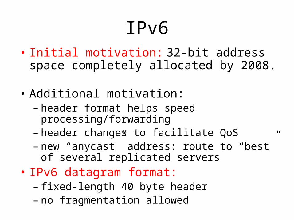
IPv6• Initial motivation: 32-bit address space
completely allocated by 2008. • Additional motivation:
– header format helps speed processing/forwarding– header changes to facilitate QoS – new “anycast” address: route to “best” of several
replicated servers
• IPv6 datagram format: – fixed-length 40 byte header– no fragmentation allowed
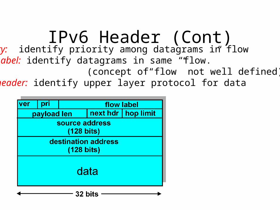
IPv6 Header (Cont)Priority: identify priority among datagrams in flowFlow Label: identify datagrams in same “flow.” (concept of“flow” not well defined).Next header: identify upper layer protocol for data
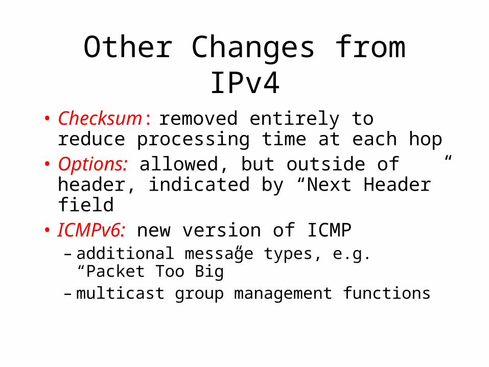
Other Changes from IPv4
• Checksum: removed entirely to reduce processing time at each hop
• Options: allowed, but outside of header, indicated by “Next Header” field
• ICMPv6: new version of ICMP– additional message types, e.g. “Packet Too
Big”– multicast group management functions
Transition From IPv4 To IPv6• Not all routers can be upgraded simultaneous
– no “flag days”– How will the network operate with mixed IPv4 and
IPv6 routers?
• Two proposed approaches:– Dual Stack: some routers with dual stack (v6, v4)
can “translate” between formats– Tunneling: IPv6 carried as payload in IPv4
datagram among IPv4 routers