Embed Size (px)
Citation preview

1
Sami TABBANE
IoT Long Range Technologies:
Standards
December 2017

2
Summary
A. Fixed & Short Range
B. Long Range technologies
1. Non 3GPP Standards (LPWAN)
2. 3GPP Standards

3
LONG RANGE TECHNOLOGIES
2
3
1
2
3
1
NB-IOT
LTE-MLORA
Weightless
EC-GSM
3GPP StandardsNon 3GPP Standards
SIGFOX
45G
4Others

4
Wide-area M2M technologies and IoT
H. S. Dhillon et al., “Wide-Area Wireless Communication Challenges for the Internet of Things,” IEEE Communications Magazine, February 2017

5
B. Non 3GPP Standards (LPWAN)
i. LoRaWAN
ii. Sigfox
iii. RPMA
iv. Others

6
LPWAN REQUIREMENTS
LPWAN
Long battery life
Low device cost
Low cost and easy
deployment
Extended coverage (10-15
km in rural areas, 2-5 km in urban
areas)
Support for a massive
number of devices

7
i. LoRaWAN

8
Roadmap
Cycleo developed LoRa technology
Semtech develop LoRaWAN network
Creation of LoRa alliance
Amsterdam become the first city covered by the LoRaWAN network
2010
2013
2015
Jun 2015
By the end of 2016
All France territory covered by LoRaWAN network:Bouygues Telecom
Differences between LoRa and LoRaWAN
• LoRa contains only the link layer protocol. LoRa modules are a little cheaper that the
LoRaWAN ones.
• LoRaWAN includes the network layer too so it is possible to send the information to any
Base Station already connected to a Cloud platform. LoRaWAN modules may work in
different frequencies by just connecting the right antenna to its socket.

9
LoRa Alliance
International
Operators
International development of
the solution
Integrators and industrialists
Appropriate technology and maintain it over
time
Manufacturers of
End-points
Broadcast end devices
Manufacturers of
Semiconductors
Integrate LoRa technology

10
LoRa technology Overview
LoRaWAN is a Low Power Wide Area Network
LoRa modulation: a version of Chirp Spread Spectrum (CSS)
with a typical channel bandwidth of 125KHz
High Sensitivity (End Nodes: Up to -137 dBm, Gateways: up to
-142 dBm)
Long range communication (up to 15 Km)
Strong indoor penetration: With High Spreading Factor, Up to
20dB penetration (deep indoor)
Occupies the entire bandwidth of the channel to broadcast a
signal, making it robust to channel noise.
Resistant to Doppler effect, multi-path and signal weakening.

11
Architecture
Customer IT
Remote Monitoring
Cloud
NetworkServer Application
Server
LoRaGateway
End Device
End Device
End Device
End Device
LoRaGateway
TCP/IP SSL
Modulation LoRa RF (Spread Spectrum)
Range ~ 15 Km
Throughput 0.3 to 27 Kbps
Type of Traffic Data packet
Payload ~ 243 Bytes
Security AES Encryption

12
Spread spectrum basics

13
Spectrum
AmplitudeGain when recovering the
initial signal
SF 12: High gain, low data rateFar devices and deep indoor
SF 9: Average gain, average data rate
SF 7: Low gain , high data rate
"Spread" signal transmitted with constant rate
Frequency
o Orthogonal sequences: 2 messages, transmitted by 2 different objects, arriving
simultaneously on a GW without interference between them (Code Division Multiple
Access technique: CDMA , used also in 3G).
o Spread Spectrum: Make the signal more robust , the more the signal is spread the
more robust. Less sensitive to interference and selective frequency fadings .
Spectrum: unlicensed, i.e. the 915 MHz ISM band in the US, 868 MHz in Europe

14
Spectrum (Influence of the Spreading Factor)
Far with obstacles:
High sensitivity required
The network increases the SF (Spreading Factor)
Throughput decreases but the connection is maintained
Close:
Low sensitivity sufficient
Decrease of SF (SPREADING FACTOR), increase of throughput
Adaptive throughputADR: Adaptive Data Rate

15
RSSI and SF versus BW
16
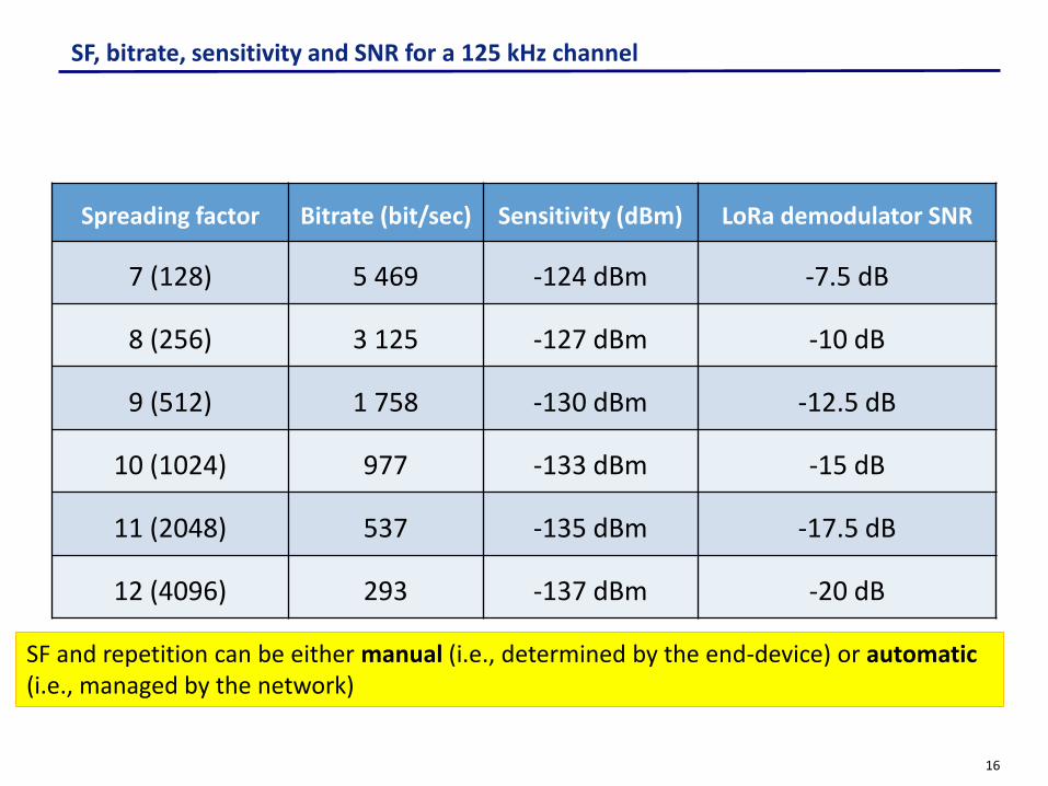
SF, bitrate, sensitivity and SNR for a 125 kHz channel
Spreading factor Bitrate (bit/sec) Sensitivity (dBm) LoRa demodulator SNR
7 (128) 5 469 -124 dBm -7.5 dB
8 (256) 3 125 -127 dBm -10 dB
9 (512) 1 758 -130 dBm -12.5 dB
10 (1024) 977 -133 dBm -15 dB
11 (2048) 537 -135 dBm -17.5 dB
12 (4096) 293 -137 dBm -20 dB
SF and repetition can be either manual (i.e., determined by the end-device) or automatic(i.e., managed by the network)

17
LoRaWAN: device classes
Description
Classes Description Intended Use Consumption Examples of Services
A(« all »)
Listens only after end device
transmission
Modules with no latency constraint
The most economic communication Class
energetically..Supported by all modules.
Adapted to battery powered modules
• Fire Detection
• Earthquake Early Detection
B(« beacon »)
The module listens at a regularly
adjustable frequency
Modules with latency constraints for the
reception of messages of a few
seconds
Consumption optimized.Adapted to battery powered
modules
• Smart metering
• Temperature rise
C(« continuous »)
Module always listening
Modules with a strong reception
latency constraint (less than one
second)
Adapted to modules on the grid or with no power constraints
• Fleet management
• Real Time Traffic Management
Any LoRa object can transmit and receive data

18
Class A
End PointGateway
One packet sent
RX1
RX2
1st receive window
1 sec +/- 20 us
1 sec +/- 20 us
Listening period
Listening period
Listening period: varies according to the
spreading factor SF
• 5.1 ms at SF7 (outdoor and close devices)
• 10.2 ms at SF8 …
• 164 ms at SF12 (deep-indoor or far devices)
2nd receive window
• Very economic energetically• Communication triggered by the
end device
Open 2 windows for DL reception
(acknowledgments, MAC commands, application
commands...) after sending a packet

19
Class B (Synchronized mode)
• Synchronized with the GTW
• Opens listening windows at
regular intervals.
End PointGateway
Opens N reception windows between the two tags
End tag
Listening duration: varies according to the SF
Rx1
Listening duration
Rx2
Rx3
RxN
Beginning tag
• Optimized energy consumption• Communication initiated by the
GTW
Listening duration
Listening duration
Listening duration

20
Class C
- Permanent listening - Closes the reception window only during transmissions
End PointGateway
Packet transmissionTX
Reception window always open
Reception window is open
Closed receive window
Adapted to devices on the power grid
Packet reception: possible
Packet reception: possible

21
Identification of an end device in LORA
End-device address (DevAddr):
Application identifier (AppEUI): A global application ID in the IEEE EUI64 address space
that uniquely identifies the owner of the end-device.
Network session key (NwkSKey): A key used by the network server and the end-device
to calculate and verify the message integrity code of all data messages to ensure data
integrity.
Application session key (AppSKey): A key used by the network server and end-device to
encrypt and decrypt the payload field of data messages.
Network identifier network address of the end-device
7 bits 25 bits
22
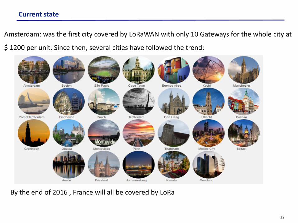
Current state
Amsterdam: was the first city covered by LoRaWAN with only 10 Gateways for the whole city at
$ 1200 per unit. Since then, several cities have followed the trend:
By the end of 2016 , France will all be covered by LoRa

23
ii. Sigfox

24
2014
First fundraising of Sigfox
company to cover France
Launch of the Sigfox network
2012 2013
All France territory is covered by Sigfox network
Mars2016
San-Francisco become the first US. State covered by Sigfox
By the end of 2016
Sigfox in America in
100 U.S. cities
Roadmap

25
First LPWAN Technology
The physical layer based on an Ultra-Narrow
band wireless modulation
Proprietary system
Low throughput ( ~100 bps)
Low power
Extended range (up to 50 km)
140 messages/day/device
Subscription-based model
Cloud platform with Sigfox –defined API for
server access
Roaming capability
Sigfox Overview

26
Architecture
Customer IT
Remote Monitoring
Cloud
NetworkServer Network
Server
SigfoxGateway
End Device
End Device
End DeviceSigfox
Gateway
TCP/IP SSL
Frequency Band Ultra Narrow Band
Range ~ 13 Km
Throughput ~ 100 bps
Type of Traffic Data packet
Payload ~ 12 Bytes
Security No security
Time on air Up to 6 seconds
End Device
By default, data is conveyed over the air interface without any encryption. Sigfox gives customers the option to either implement their own end-to-end encryption solutions.

27
Spectrum and access
Narrowband technology
Standard radio transmission method: binary phase-shift keying (BPSK)
Takes very narrow parts of spectrum and changes the phase of the carrier radio
wave to encode the data
Frequency spectrum:
868 MHz in Europe
915 MHz in USA

28
ITU ASP RO
• Starts by an UL transmission
• Each message is transmitted 3 times
• A DL message can be sent (option)
• Maximum payload of UL messages = 12 data bytes
• Maximum payload of DL messages = 8 bytes
Sigfox transmission

29
Current state
SIGFOX LPWAN deployed in France, Spain, Portugal, Netherlands, Luxembourg, and
Ireland , Germany, UK, Belgium, Denmark, Czech Republic, Italy, Mauritius Island,
Australia, New Zealand, Oman, Brazil, Finland, Malta, Mexico, Singapore and U.S.
Sigfox company objectives:
Cover China in 2017
60 countries covered by the end of 2018
Covered countries Covered areas End devices
26 Countries
26 Countries
1.6 million
Km²
1.6 million
Km²
424 million
424 million

30
iii. RPMA

31
September 2015
RPMA was developedby On-Ramp Wireless to provide connectivity to oil and gasactors
2008
it was renamed Ingenu, andtargets to extend its technology to the IoT and M2Mmarket
2016
RPMA was implemented in many places Austin, Dallas/Ft. worth,Hostton,TX,Phenix,AZ,….
2017
RPMA will be invaded in many others countries: Los Angeles, San Franscisco-West Bay,CA,Washington,DC, Baltimore,MD, Kanasas City
Roadmap

32
INGENU RPMA overview
Random Phase Multiple Access (RPMA)
technology is a low-power, wide-area
channel access method used exclusively
for machine-to-machine (M2M)
communication
RPMA uses the 2.4 GHz band
Offer extreme coverage
High capacity
Allow handover (channel change)
Excellent link capacity
33
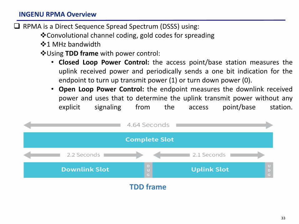
INGENU RPMA Overview
RPMA is a Direct Sequence Spread Spectrum (DSSS) using:Convolutional channel coding, gold codes for spreading1 MHz bandwidthUsing TDD frame with power control:
• Closed Loop Power Control: the access point/base station measures theuplink received power and periodically sends a one bit indication for theendpoint to turn up transmit power (1) or turn down power (0).
• Open Loop Power Control: the endpoint measures the downlink receivedpower and uses that to determine the uplink transmit power without anyexplicit signaling from the access point/base station.
TDD frame

34
Time/Frequency Synchronization
Uplink Power Control
Creating a very tightly power controlled system in free-spectrum and presence of
interference which reduces the amount of required endpoint transmit power by a
factor of >50,000 and mitigates the near-far effect.
Frame structure to allow continuous channel tracking.
Adaptive spreading factor on uplink to optimize battery consumption.
Handover
Configurable gold codes per access point to eliminate ambiguity of link communication.
Frequency reuse of 3 to eliminate any inter-cell interference degradation.
Background scan with handover to allow continuous selection of the best access point
Specifications of RPMA Solution
35
Downlink Data Rate Optimization
Very high downlink capacity by use of adaptive downlink spreading factors.
Open loop forward error correction for extremely reliable firmware download.
Open loop forward error correction to optimize ARQ signaling. Signaling only needs to
indicate completion, not which particular PDUs are lost.
Specifications of RPMA Solution

36
RPMA a Random multiple access Network
Random multiple access is performed by delaying the signal to transmit at each end-device
Support up to 1000 end devices simultaneously For the uplink, or the downlink broadcast transmission, a unique Gold code is
used. For unicast downlink transmission, the Gold code is built with the end-device
ID, such that no other end-device is able to decode the data.

37
INGENU RPMA architecture
Cloud
NetworkServer Network
Server
Access Point
End Device
TCP/IP SSL
Access Point
Backhaul(Ethernet, 3G, WiFi,
...)
Frequency Band 2.4 GHZ
Range 5-6 Km
Throughput 624 kb/s (UL) and 156 kb/s (DL)
Type of Traffic Data packet
Payload ~ 16 Bytes (one end point) ~ 1600 Bytes (for 1000 end points
Security AES Encryption
Customer IT
Remote Monitoring

38
Uplink Subslot Structure
Uplink Subslot Structure Supporting Flexible Data Rate
Step 1: Choose Spreading factor from 512 to 8192Step 2: randomly select subslotStep 3: Randomly select delay to add to subslot start from 0 to 2048 chips

39
End Point Access Point
Registration request (how often the EP will communicate)
Assigned a bit on the BCH channel (enable to send or No)
Send the message (payload 16 bytes)
AP response ( Ack or NACK): Successful transaction
Not OK send again
Send the message
Send Acknowledge
How end point can transfer a data?

40
RPMA security
Message confidentiality: use of powerful encryption
Message integrity1 Replay protection
Mutual Authentication
Device AnonymityAuthentic firmware
UpgradesSecure Multicasts

41
heavy presence in Texas, with networks in Dallas, Austin, San Antonio, Houston, and large white space areas.
Ingenu offer the connectivity to more 50% of the Texas state population.
Three densely populated Texas markets are served by only 27 RPMA access points
RPMA currently provides more than 100,000 square miles of wireless coverage for a host of IoT applications.
Ingenu will be expanding its coverage to dozens of cities in the next few years.
RPMA’s current and future presence

42
Currently live Coverage Rollout Q3
Coverage ROLLOUT Q4 2016
Coverage planned2017
• Austin,TX• Dallas/Ft.worth,
TX• Hostton,TX• Phenix,AZ• Riverside,CA• San Antonio,TX• San Diego,CA
• Columbus, OH• Indianapolis,IN
• Atlanta,GA• Jacksonville,FL• Miami,FL• Oriando,FL• New Orleans,LA• Charlotte,NC• Albuquerque• Memphis,TN• Nashville,TN EL
paso,TX• Salt Lake City,UT• Richmound,• Virginia
beach,VA
• Los Angeles,CA• San Franscisco-
West Bay,CA• Washington,DC• Baltimore,MD• Kanasas City• Greeensboro,NC• Las Vegas,NV• Oklahorma City,
OK• And many more
cities
RPMA’s current and future presence

43
v. Others

44
EnOcean
Based on miniaturized power converters
Ultra low power radio technology
Frequencies: 868 MHz for Europe and 315 MHz for the USA
Power from pressure on a switch or by photovoltaic cell
These power sources are sufficient to power each module to transmit wireless
and battery-free information.
EnOcean Alliance in 2014 = more than 300 members (Texas, Leviton, Osram,
Sauter, Somfy, Wago, Yamaha ...)

45
EnOcean
Architecture

46
ZWave
Low power radio protocol
Home automation (lighting, heating, ...) applications
Low-throughput: 9 and 40 kbps
Battery-operated or electrically powered
Frequency range: 868 MHz in Europe, 908 MHz in the US
Range: about 50 m (more outdoor, less indoor)
Mesh architecture possible to increase the coverage
Access method type CSMA / CA
Z-Wave Alliance: more than 100 manufacturers in

47
ZWave
Services

48
Summary
A. Fixed & Short Range
B. Long Range technologies
1. Non 3GPP Standards (LPWAN)
2. 3GPP Standards

49
2. 3GPP Standards
i. LTE-M
ii. NB-IOT
iii. EC-GSM
iv. 5G and IoT

50
Release-13 3GPP evolutions to address the IoTmarket
eMTC: LTE enhancements for
MTC, based on Release-12
(UE Cat 0, new PSM, power
saving mode)
NB-IOT: New radio added to
the LTE platform optimized
for the low end of the market
EC-GSM-IoT: EGPRS
enhancements in
combination with PSM to
make GSM/EDGE markets
prepared for IoT

51
Release 14 eMTC enhancements
Main feature enhancements
• Support for positioning (E-CID and OTDOA)
• Support for Multicast (SC-PTM)
• Mobility for inter-frequency measurements
• Higher data rates
• Specify HARQ-ACK bundling in CE mode A in HD-FDD
• Larger maximum TBS
• Larger max. PDSCH/PUSCH channel bandwidth in connected mode at least in CE mode A in order to enhance support e.g. voice and audio streaming or other applications and scenarios
• Up to 10 DL HARQ processes in CE mode A in FD-FDD
• Support for VoLTE (techniques to reduce DL repetitions, new repetition factors, and adjusted scheduling delays)

52
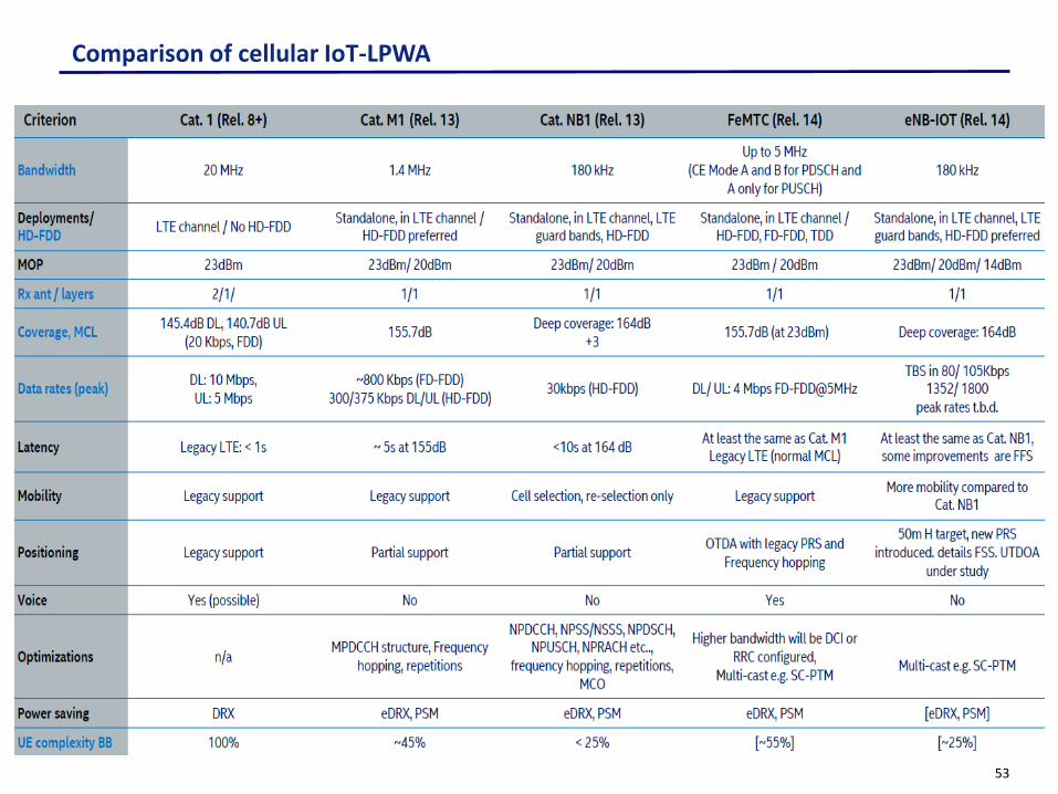
Main eMTC, NB-IoT and EC-GSM-IoT features
53
Comparison of cellular IoT-LPWA

54
i. LTE-M

55
Technology
• Evolution of LTE optimized for IoT
• Low power consumption and extended autonomy
• Easy deployment
• Interoperability with LTE networks
• Low overall cost
• Excellent coverage: up to 11 Km
• Maximum throughput: ≤ 1 Mbps

56
Roadmap
• First released in Rel.1in 2 Q4 2014
• Optimization in Rel.13
• Specifications completed in Q1 2016
• Available in 2017 (?)

57
LTE to LTE-M
3GPP Releases 8 (Cat.4) 8 (Cat. 1) 12 (Cat.0) LTE-M 13 (Cat. 1,4 MHz) LTE-M
Downlink peak rate (Mbps) 150 10 1 1
Uplink peak rate (Mbps) 50 5 1 1
Number of antennas (MIMO) 2 2 1 1
Duplex Mode Full Full Half Half
UE receive bandwidth (MHz) 20 20 20 1.4
UE Transmit power (dBm) 23 23 23 20
• New category of UE (“Cat-0”): lower
complexity and low cost devices
• Half duplex FDD operation allowed
• Single receiver
• Lower data rate requirement (Max: 1 Mbps)
• Reduced receive bandwidth to 1.4 MHz
• Lower device power class of 20 dBm
• 15dB additional link budget: better coverage
• More energy efficient because of its extended
discontinuous repetition cycle (eDRX)
Release 12 Release 13

58
Architecture
Present LTE Architecture

59
Architecture
End Device
End Device
New baseband Softwarefor LTE-M
Remote Monitoring
Customer IT
LTE Access
Frequency Band Narrow Band
Access LTE-M
Range ~ 11 Km
Throughput ~ 1 Mbps

60
Spectrum and access
• Licensed Spectrum
• Bandwidth: 700-900 MHz for LTE
• Some resource blocks allocated for IoT on LTE bands

61
ii. NB-IOT

62
Current status
Narrowband proposal to Connected
Living
3GPP ‘Cellular IoT’ Study Item
GSMA Mobile IoT
created
3GPP alignment on
single standard
1st live pre-standard NB-IoT
message
Full NB-IoT 3GPP
Standard Released
Commercial rollout
April 2014
May 2014
Mars 2015
August 2015
November 2015
Jun2015
2017+
Evolution of LTE-M

63
NB-IoT main features and advantages
Reuses the LTE design extensively:numerologies, DL OFDMA, UL SC-FDMA, channelcoding, rate matching, interleaving, etc.
Reduced time to develop:
Full specifications.
NB-IoT products for existing LTE equipmentand software vendors.
June 2016: core specifications completed.
Beginning of 2017: commercial launch ofproducts and services.

64
Frame and Slot Structure – NB-IoT – 7 symbols per slot

65
NB-IoT Channels
Frame structure
Signals: PSS, SSS - RS
Broadcast Channel
Dedicated Channels
NPBCHNPDCCH
NPDSCH
Downlink
Uplink
Physical Layer
Frame structure
Signals: Demodulation reference signals (DMRS)
Random Access
Dedicated Channels
NPRACHNPDCCH
NPUSCHUsed for data and HARQ feedback

66
Physical downlink channels
Maximum Transmission Block Size = 680 bitsInband mode: 100 to 108 symbols – Standalone/Guard band mode: 152 to 160 symbols

67
Downlink Frame Structure

68
UL frame structure
UL frame structureSingle-Tone (mandatory):To provide capacity in signal-strength-limited scenarios and dense capacity• Number of subcarriers: 1• Subcarrier spacing: 15 kHz or 3.75 kHz
(via Random access)• Slot duration: 0.5 ms (15 kHz) or 2 ms
(3.75 kHz)Multi-tone (optional):To provide higher data rates for devices in normal coverage• Number of subcarriers: 3, 6 or 12
signaled via DCI• Subcarrier spacing: 15 kHz• Slot duration = 0.5 msNew UL signalsDMRS (demodulation referencesignals)New UL channels• NPUSCH (Physical UL Shared• Channel)• NPRACH (Physical Random Access
Channel)

69
NB-IoT Repetitions
Example: Repetitions used in NB-IoT in NPDCCH and NPDSCH channels
Consists on repeating the same transmission several times:
Achieve extra coverage (up to 20 dB compared to GPRS)
Each repetition is self-decodable
SC is changed for each transmission to help combination
Repetitions are ACK-ed just once
All channels can use Repetitions to extend coverage
15 kHz subcarrier spacing.A transport block test word (TW) is transmitted on two RUs
Each RU is transmitted over 3 subcarriers and 8 slots
DL up to 2048 repetitionsUL up to 128 repetitions

70
Repetitions number to decode a NPUSCH

71
Transmissions scheduling
Subframe

72
Release 14 enhancements
• OTDOA• UTDOA positioning is supported under the following conditions:• It uses an existing NB-IoT transmission
– It can be used by Rel-13 UEs– Any signal used for positioning needs to have its accuracy, complexity, UE power
consumption performance confirmed
Main feature enhancements:• Support for Multicast (SC-PTM)• Power consumption and latency reduction (DL and UL for 2 HARQ
processes and larger maximum TBS) • Non-Anchor PRB enhancements (transmission of NPRACH/Paging
on a non-anchor NB-IoTPRB)• Mobility and service continuity enhancements (without the
increasing of UE power consumption)• New Power Class(es) (if appropriate, specify new UE power
class(es), e.g. 14dBm)

73
Physical Channels in Downlink
Physical signals and channels in the downlink:
Narrowband primary synchronization signal (NPSS) and Narrowband secondary synchronization signal (NSSS): cell search, which includes time and frequency synchronization, and cell identity detection
Narrowband physical broadcast channel (NPBCH)
Narrowband reference signal (NRS)
Narrowband physical downlink control channel (NPDCCH)
Narrowband physical downlink shared channel (NPDSCH)

74
Uplink channels
Narrowband physical random access channel
(NPRACH): new channel since the legacy LTE
physical random access channel (PRACH)
uses a bandwidth of 1.08 MHz, more than
NB-IoT uplink bandwidth
Narrowband physical uplink shared channel
(NPUSCH)

75
NPDCCH/NPDSCH resource mapping example

76
Physical signals and channels and relationship with LTE

77
Enhanced DRX for NB-IOT and eMTC
Extended C-DRX and I-DRX operation
• Connected Mode (C-eDRX):
• Extended DRX cycles of 5.12s and 10.24s are supported
• Idle mode (I-eDRX):
• Extended DRX cycles up to ~44min for eMTC
• Extended DRX cycles up to ~3hr for NB-IOT

78
Architecture
End Device
End Device
New baseband Softwarefor NB-IoT
Remote Monitoring
Customer IT
LTE Access
Frequency Band Ultra Narrow Band
Range ~ 11 Km
Throughput ~ 150 Kbps

79
Spectrum and access
• Designed with a number of deployment options for GSM , WCDMA or LTE spectrum to achieve spectrum efficiency.
• Use licensed spectrum. Stand-alone operation
Dedicated spectrum.
Ex.: By re-farming GSM channels
Guard band operation
Based on the unused RB within a LTE
carrier’s guard-band
In-band operation
Using resource blocks within a normal LTE
carrier

80
LTE-M to NB-IoT
3GPP Release12 (Cat.0)
LTE-M13(Cat. 1,4 MHz)
LTE-M13(Cat. 200 KHz)
NB-IoT
Downlink peak rate 1 Mbps 1 Mbps300 bps to 200
kbps
Uplink peak rate 1 Mbps 1 Mbps 144 kbps
Number of antennas 1 1 1
Duplex Mode Half Half Half
UE receive bandwidth 20 MHz 1.4 MHz 200 kHz
UE Transmit power (dBm) 23 20 23
• Reduced throughput based on single PRB operation
• Enables lower processing and less memory on the modules
• 20dB additional link budget better area coverage

81
Vodafone announced the commercialization of NB-IoT
Announced the commercialization of NB-IoT on 23rd Jan 17
1000 sites activated NB-IoT in Spain by the end of march 2017
Took just a few hours to deploy NB-IoT with software upgrade in Valencia
Madrid, Valencia, Barcelona is covered, Plan to cover 6 cities in 2017H1
4 countries in Europe (Germany, Ireland, the Netherlands and Spain) will commercially launch NB-IoT in 2017.
Source: Huawei

82
Shanghai Unicom:
NB-IoT Network Coverage
• 800+ base stations covered
Shanghai in 2016Q4
Network readiness accelerates the development of vertical customers
China Unicom: 800+ Sites Activated NB-IoT in Shanghai
Parking operator Gas Utility Fire center
Smart Parking Smart Gas Meter Smart Fire Protection
Source: Huawei

83
• 2017H1, NB-IoT enabled
in L850 to achieve
national wide coverage
Use cases
Share bicycle
China Telecom: NB-IoT Nationwide Coverage in 2017H1
• 100 NB-IoT bicycles test in Beijing
University in Q2 2017
• 100K bicycles in Beijing city by
September 2017
• China Telecom to provide NB-IoT
coverage in whole Beijing by June 2017
• Mar 22 2017, Shenzhen water
utility announced
commercialization;
• 1200 meters (phase 1)
running in live network;
NB-IoT Pre commercial
NB-IoT Trial
NB-IoT commerci
al
Jie Yang, Board chairTrial
Test
commercial
Source: Huawei

84
iii. EC-GSM

85
Roadmap
May 2014 Aug 2015 Sep 2015 Dec 2015 Mars 2016
2020: 15% connections excluding cellular IoT will still be on 2G in Europe and 5% in the US (GSMA predictions). GPRS is responsible for most of today’s M2M communications

86
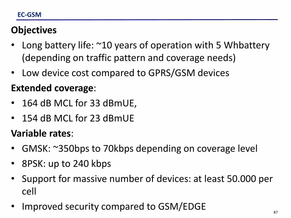
EC-GSM
EC-GSM-IoT Objectives: Adapt and leverage existing 2G infrastructure to provide efficient
and reliable IoT connectivity over an extended GSM Coverage
Long battery life: ~10 years of operation with 5 Wh battery (depending on traffic
pattern and coverage extension)
Low device cost compared to GPRS/GSM device
Variable data rates:
• GMSK: ~350bps to 70kbps depending on coverage extension
• 8PSK: up to 240 kbps
Support for massive number of devices: ~50.000 devices per cell
Improved security adapted to IoT constraint.
Leverage on the GSM/GPRS maturity to allow fast time to market and low cost
87
EC-GSM
Objectives
• Long battery life: ~10 years of operation with 5 Whbattery(depending on traffic pattern and coverage needs)
• Low device cost compared to GPRS/GSM devices
Extended coverage:
• 164 dB MCL for 33 dBmUE,
• 154 dB MCL for 23 dBmUE
Variable rates:
• GMSK: ~350bps to 70kbps depending on coverage level
• 8PSK: up to 240 kbps
• Support for massive number of devices: at least 50.000 per cell
• Improved security compared to GSM/EDGE

88
EC-GSM
Main PHY features• New logical channels designed for extended coverage • Repetitions to provide necessary robustness to support up to 164
dB MCL • Overlaid CDMA to increase cell capacity (used for EC-PDTCH and EC-
PACCH)Other features• Extended DRX (up to ~52min)• Optimized system information (i.e. no inter-RAT support)• Relaxed idle mode behavior (e.g. reduced monitoring of neighbor
cells)• 2G security enhancements (integrity protection, mutual
authentication, mandate stronger ciphering algorithms)• NAS timer extensions to cater for very low data rate in extended
coverage• Storing and usage of coverage level in SGSN to avoid unnecessary
repetitions over the air

89
EC-GSM
Extended coverage (~ 20 dB compared to GSM coverage)
GSM900 LoRa
Sens de la LiaisonMontante Unités Montante
Partie Réception BTS GW
Sensibilité -104 dBm -142
Marge de protection 3 dB 0
Perte totale câble et connecteur 4 dB 4
Gain d'antenne (incluant 5 dB de diversité) -17 dBi -6
Marge de masque (90% de la surface) 5 dB 5
Puissance médiane nécessaire -109 dBm -141
Partie Emission MS Capteur
Puissance d'émission (GSM Classe 2 = 2W) Bilan de liaison
33 dBm 20
Affaiblissement maximal 142 dB 161
Pertes dues au corps humain -3 dB 0
Affaiblissement de parcours (bilan de liaison) 139 dB 161

90
EC-GSM
Deployment
To be deployed in existing GSM spectrum without any impact on network planning.
EC-GSM-IoT and legacy GSM/GPRS traffic are dynamically multiplexed.
Reuse existing GSM/GPRS base stations thanks to software upgrade.
Main PHY features:
New “EC” logical channels designed for extended coverage
Repetitions to provide necessary robustness to support up to 164 dB MCL
Fully compatible with existing GSM hardware design (Base station and UE)
IoT and regular mobile traffic are share GSM time slot.

91
EC-GSM
Coverage Extension: 4 different coverage class
Channels CC1 CC2 CC3 CC4
DL
MCL(dB) 149 157 161 164
EC-CCCH 1 8 16 32
EC-PACCH 1 4 8 16
EC-PDTCH 1 4 8 16
UL
MCL(dB) 152 157 161 164
EC-CCCH 1 4 16 48
EC-PACCH 1 4 8 16
EC-PDTCH 1 4 8 16
Beacon and Synchronization channel don’t use coverage class EC-BCCH: always repeated 16 times EC-SCH: always repeated 28 times FCCH: legacy FCCH is used.
Mapped on TS 1

92
EC-GSM
Other features:
Support of SMS and Data, but no voice
Extended DRX (up to ~52min) [ GSM DRX ~11 min]
Optimized system information (i.e. no inter-RAT support)
Relaxed idle mode behavior (e.g. reduced monitoring of neighbor cells)
2G security enhancements (integrity protection, mutual authentication, mandate
stronger ciphering algorithms)
NAS timer extensions to cater for very low data rate in extended coverage
Storing and usage of coverage level in SGSN to avoid unnecessary repetitions over the
air
Optional mobility between GSM and EC-GSM

93
Architecture
IP Networks
GSM Access
Mobile UE
Actual GSM/GPRS Architecture
2G-based NB-IoT networks should come at the end of 2017, with LTE following around 12 months later

94
Architecture
End Device
End Device
New baseband Software
for EC-GSM
Remote Monitoring
Customer IT
GSM Access
IP Networks
Mobile UE
Update for EC-GSM
Access EC-GSM
Frequency Band Narrow Band
Range ~ 15 Km
Throughput ~ 10 Kbps

95
iv. 5G and IoT

96
• Initial technology submission: Meeting 32 (June 2019)
• Detailed specification submission: Meeting 36 (October 2020)
ITU-R WP5D
Roadmap

97
Vision of 5G
Cloud
Core network (transport)
Access networks
Services

98
Thank you!