Embed Size (px)
Citation preview

Dissertação para obtenção do Grau de Mestre em
Engenharia Eletrotécnica e de Computadores
Dissertação para obtenção do Grau de Mestre em
[Engenharia Informática]
Orientador: Ricardo Jardim Gonçalves, Professor Auxiliar com Agregação,
Faculdade de Ciências e Tecnologia da Universidade Nova de
Lisboa
Co-orientador: Sudeep Ghimire, Estudante de Doutoramento, Faculdade de
Ciências e Tecnologia da Universidade Nova de Lisboa
Júri:
Presidente: Professor Doutor Anikó Katalin
Horváth da Costa
Arguente: Professor Doutor João
Francisco Alves Martins
Vogais: Doutor Sudeep Ghimire
Pedro Miguel Machado Monteiro Costa
[Nome completo do autor]
[Nome completo do autor]
[Nome completo do autor]
[Nome completo do autor]
[Nome completo do autor]
[Nome completo do autor]
[Nome completo do autor]
IoT for Efficient Data Collection from Real World
Resources
[Título da Tese]
Licenciado em Ciências da Engenharia
Eletrotécnica e de Computadores
[Habilitações Académicas]
[Habilitações Académicas]
[Habilitações Académicas]
[Habilitações Académicas]
[Habilitações Académicas]
[Habilitações Académicas]
[Habilitações Académicas]
Setembro 2016

ii
iii
IoT for Efficient Data Collection from Real World Resources
Copyright © Pedro Miguel Machado Monteiro Costa, Faculdade de Ciências e Tecnologia,
Universidade Nova de Lisboa.
A Faculdade de Ciências e Tecnologia e a Universidade Nova de Lisboa têm o direito, perpétuo
e sem limites geográficos, de arquivar e publicar esta dissertação através de exemplares
impressos reproduzidos em papel ou de forma digital, ou por qualquer outro meio conhecido
ou que venha a ser inventado, e de a divulgar através de repositórios científicos e de admitir a
sua cópia e distribuição com objetivos educacionais ou de investigação, não comerciais, desde
que seja dado crédito ao autor e editor.

iv

v
For my parents, sister and girlfriend

vi
vii
Acknowledgements
At the end of a long and demanding course, I would like to thank all the people who in some
way, contributed to the success of this stage of my life.
First of all, I would give the biggest thanks to my family, specially my parents, sister and girlfriend
that supported me all these years, always with an enormous willingness to help. But also my
grandparents, uncles, aunts and cousins for their giant contribution in different ways.
To my advisor Dr. Ricardo Gonçalves, my teacher José Ferreira and the coordinator of C2NET
project Carlos Agostinho for giving me a great opportunity to work in a GRIS’s project and
believing in my capabilities to complete this thesis.
To all the people at GRIS, specially to my joint supervisor Sudeep Ghimire that helped and
believed in me all this time, pushing me to do a better work and to successfully complete this
dissertation. To Pedro Simões for transmitting his enormous knowledge and his great help
during the implementation part.
Finally, to my special friends who shared with me the good and the bad times, making this step
more fun, easy and absolutely memorable.

viii

ix
Abstract
_____________________________________________________________________________
The Internet of Things is providing new ways of experiencing and reacting to the physical world
through the ability of advanced electronic devices that collect data. At the same time, as new
application scenarios are envisioned, with the assistance of information generated by sensors,
new problems and obstacles will arise. This requires new development to meet business and
technical requirements, such as interoperability between heterogeneous devices and
confidence (such as validity, security and trust) over smart devices. With the increase of these
complex requirements it becomes crucial to develop an infrastructure aimed at tackling such
requirements mentioned. IoT middleware – a software layer that bridges the gap between
devices and information systems. Thus, this work aims to study the mechanisms and
methodology for data collection, devices interoperability and data filtering, closer to the data
sources, in order to optimize the collection and pre-analysis of data that can then be used by
various applications such as the ones in manufacturing industry.
Keywords: Data Acquisition, Data Filtering, Internet of Things, Middleware, Sensors,
Interoperability
_____________________________________________________________________________

x

xi
Resumo
_____________________________________________________________________________
A Internet das Coisas vem providenciar às pessoas uma nova forma de sentir e reagir aos aspetos
do mundo físico, através da capacidade que os avançados dispositivos eletrónicos têm
atualmente na recolha de informação. Paralelamente, novos cenários de aplicabilidade, nas
mais diversas áreas, que advém do uso da informação recolhida pelos sensores, começaram a
surgir e, diversos problemas e obstáculos prevalecem. Portanto, é necessário novos
desenvolvimentos que satisfaçam os requisitos técnicos e de negócios, tais como a
interoperabilidade entre dispositivos heterogéneos e a confiança (em aspetos como a validade,
segurança e fiabilidade) que os dispositivos inteligentes asseguram. Com o aumento da
complexidade deste conceito, surgiu uma infraestrutura que visa solucionar os importantes
requisitos mencionados. IoT Middleware – uma camada de software que faz a ponte entre os
dispositivos e a infraestrutura. Assim, esta dissertação pretende estudar os mecanismos e
metodologias de recolha de dados, interoperabilidade de dispositivos e pré-filtragem de dados,
perto da fonte de recolha, com o intuito de otimizar a sua recolha e pré-análise de dados que
podem ser usadas em várias aplicações, como por exemplo, na indústria da manufatura.
Palavras-Chave: Recolha de dados, Filtragem de dados, Internet das Coisas, Middleware,
Sensores, Interoperabilidade

xii
xiii
Index
1. Introduction .......................................................................................................................... 1
1.1. Motivation Scenario – IoT .................................................................................................. 3
1.2. Research question .............................................................................................................. 5
1.3. Hypothesis .......................................................................................................................... 6
1.4. Work Methodology ............................................................................................................ 6
1.5. Dissertation Outline ........................................................................................................... 8
2. State-Of-Art ........................................................................................................................... 9
2.1. Overview ............................................................................................................................ 9
2.1.1. Internet of Things ........................................................................................................ 9
2.1.2. Middleware for Data Acquisition .............................................................................. 10
2.1.3. Data Collection from Sensors – Context Acquisition ................................................ 12
2.1.4. IoT Protocols .............................................................................................................. 17
2.1.5. Data Pre-processing .................................................................................................. 22
2.2. IoT Deployment Scenarios ............................................................................................... 25
2.2.1. Peer-to-Peer Devices ................................................................................................. 26
2.2.2. Devices to Service Providers ..................................................................................... 28
2.2.3. Devices to Middleware to Service Providers ............................................................. 30
2.3. Middleware Solutions for Internet of Things ................................................................... 33
2.3.1. Domain ...................................................................................................................... 33
2.3.2. Approach ................................................................................................................... 34
2.3.3. Synthesis .................................................................................................................... 38
3. Hub Architecture ................................................................................................................. 39
3.1. Overview .......................................................................................................................... 39
3.2. Concept ............................................................................................................................ 42
3.3. Application Scenario ......................................................................................................... 44
3.3.1. Smart-Shopfloor Scenario ......................................................................................... 46
4. Proof of Concept Implementation ...................................................................................... 49
4.1. Requirements and Functionalities ................................................................................... 49
4.2. Technology Adopted ........................................................................................................ 51
4.2.1. Software Technology ................................................................................................. 51
4.2.2. Hardware Technology ............................................................................................... 53

xiv
4.3. IoT Hub Detailed ............................................................................................................... 58
4.3.1. Controller .................................................................................................................. 58
4.3.2. Data Listeners ............................................................................................................ 59
4.3.3. Models ....................................................................................................................... 60
4.3.4. Utilities ...................................................................................................................... 60
4.3.5. Synthesis .................................................................................................................... 61
5. Testing and Hypothesis Validation ...................................................................................... 65
5.1. Testing Methodology ....................................................................................................... 65
5.1.1. Testing and Test Control Notation ............................................................................ 66
5.2 Testing Implementation .................................................................................................... 68
5.3.1. Functional Tests......................................................................................................... 69
5.3.2. Non-Functional Tests................................................................................................. 73
5.3. Hypothesis Validation ...................................................................................................... 74
5.4. Scientific and Industrial Validation ................................................................................... 75
6. Conclusions and Future Work ............................................................................................. 78
6.1. Conclusions ...................................................................................................................... 78
6.2. Future Work ..................................................................................................................... 78
References ................................................................................................................................... 80
xv
Index of Figures
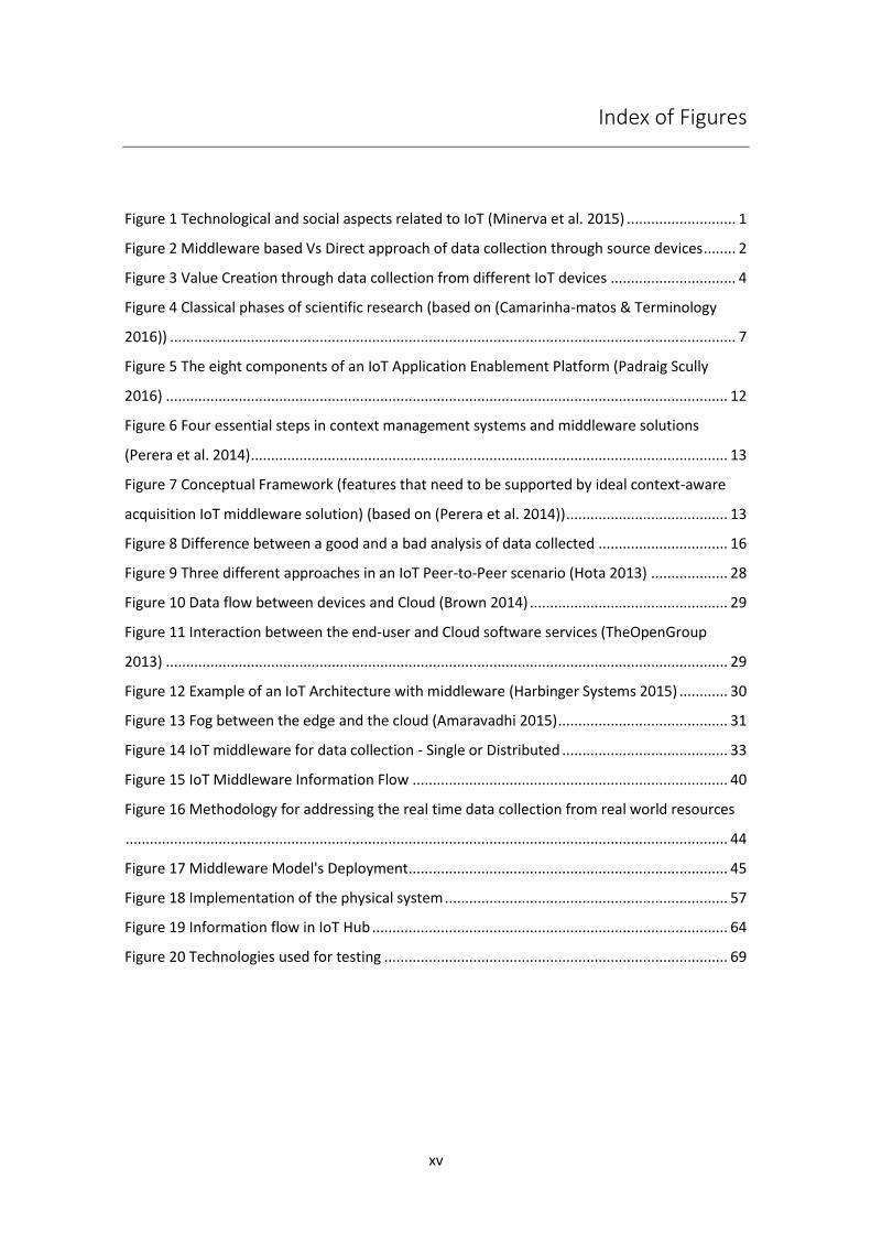
Figure 1 Technological and social aspects related to IoT (Minerva et al. 2015) ........................... 1
Figure 2 Middleware based Vs Direct approach of data collection through source devices ........ 2
Figure 3 Value Creation through data collection from different IoT devices ............................... 4
Figure 4 Classical phases of scientific research (based on (Camarinha-matos & Terminology
2016)) ............................................................................................................................................ 7
Figure 5 The eight components of an IoT Application Enablement Platform (Padraig Scully
2016) ........................................................................................................................................... 12
Figure 6 Four essential steps in context management systems and middleware solutions
(Perera et al. 2014) ...................................................................................................................... 13
Figure 7 Conceptual Framework (features that need to be supported by ideal context-aware
acquisition IoT middleware solution) (based on (Perera et al. 2014)) ........................................ 13
Figure 8 Difference between a good and a bad analysis of data collected ................................ 16
Figure 9 Three different approaches in an IoT Peer-to-Peer scenario (Hota 2013) ................... 28
Figure 10 Data flow between devices and Cloud (Brown 2014) ................................................. 29
Figure 11 Interaction between the end-user and Cloud software services (TheOpenGroup
2013) ........................................................................................................................................... 29
Figure 12 Example of an IoT Architecture with middleware (Harbinger Systems 2015) ............ 30
Figure 13 Fog between the edge and the cloud (Amaravadhi 2015) .......................................... 31
Figure 14 IoT middleware for data collection - Single or Distributed ......................................... 33
Figure 15 IoT Middleware Information Flow .............................................................................. 40
Figure 16 Methodology for addressing the real time data collection from real world resources
..................................................................................................................................................... 44
Figure 17 Middleware Model's Deployment ............................................................................... 45
Figure 18 Implementation of the physical system ...................................................................... 57
Figure 19 Information flow in IoT Hub ........................................................................................ 64
Figure 20 Technologies used for testing ..................................................................................... 69

xvi

xvii
Index of Tables
Table 1 Five main functionalities handled by an IoT middleware ............................................... 11
Table 2 IoT D2S Protocol Landscape (Duffy 2013) ..................................................................... 21
Table 3 Challenges in middleware approaches for IoT ............................................................... 38
Table 4 Examples of context data collection............................................................................... 45
Table 5 Analysis of selected sensors ........................................................................................... 48
Table 6 Information flow between the modules of the system ................................................. 61
Table 7 Example of a TTCN test in table format (Tretmans 2001) .............................................. 67
Table 8 Middleware Definition Test - Entire System ................................................................... 70
Table 9 Middleware Execution Tests - Entire System ................................................................. 73
Table 10 Non-functional test in normal conditions .................................................................... 74
Table 11 Non-functional test in abnormal conditions ................................................................ 74
Table 12 Sensors' behaviour in an abnormal situation in the hub ............................................. 74

xviii
xix
Table of Acronyms
Acronyms Definition
AMQP Advanced Messaging Queuing Protocol
API Application Programming Interface
CO Cooperating Objects
CoAP Constrained Application Protocol
D2D Device-to-Device
D2S Device-to-Service
DCF Data Collection Framework
DDS Data Distribution Service
EPC Electronic Product Code
GRIS Group for Research on Interoperability of Systems
GSN Global Sensor Networks
HTTP Hypertext Transfer Protocol
IDE Integrated Development Environment
IEEE Institute of Electrical and Electronics Engineers
IoT Internet of Things
IT Information Technology
JAR Java Archive
M2M Machine to Machine
MQTT Message Queuing Telemetry Transport
NFC Near Field Communication
PLM Product Lifecycle Management
RDF Resource Description Framework
REST Representational State Transfer

xx
Acronyms Definition
RFID Radio-Frequency Identification
ROS Robotic Operating System
RW Real World
S2S Service-to-Service
SUT System Under Test
TEDS Transducer Electronic Data Sheet
TDT Tag Data Translation
TTCN Testing and Test Control Notation
XMPP Extensible Messaging and Presence Protocol
1
1. Introduction
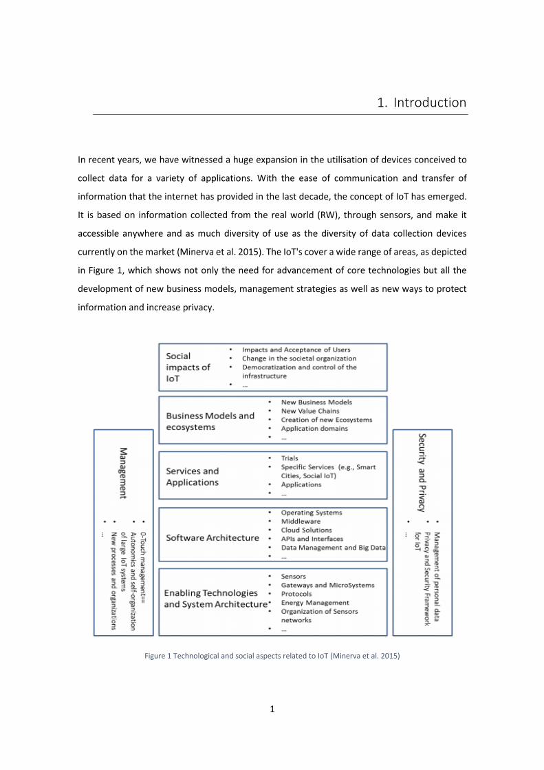
In recent years, we have witnessed a huge expansion in the utilisation of devices conceived to
collect data for a variety of applications. With the ease of communication and transfer of
information that the internet has provided in the last decade, the concept of IoT has emerged.
It is based on information collected from the real world (RW), through sensors, and make it
accessible anywhere and as much diversity of use as the diversity of data collection devices
currently on the market (Minerva et al. 2015). The IoT's cover a wide range of areas, as depicted
in Figure 1, which shows not only the need for advancement of core technologies but all the
development of new business models, management strategies as well as new ways to protect
information and increase privacy.
Figure 1 Technological and social aspects related to IoT (Minerva et al. 2015)
2
It is estimated that in 2020 there will be around 21 billion devices connected to each other, of
which 7 billion do not relate to the consumer market but to the use of devices in industrial sector
(Gartner 2015). This technological advance derives mainly from the constant search for
maximum efficiency that many companies are looking for with the purpose of increasing its self-
management in both data monitoring and in its management and control. In this perspective,
companies are looking for solutions in three major areas (Sheng et al. 2015):
Network Management - focus on quality and reliability of the hardware, such as routers
and servers;
System Management - focus on quality and reliability of software, such as data
interpretation and operating systems programs;
Application Management -concern aesthetic and reliable aspects, both in safety and
operability.
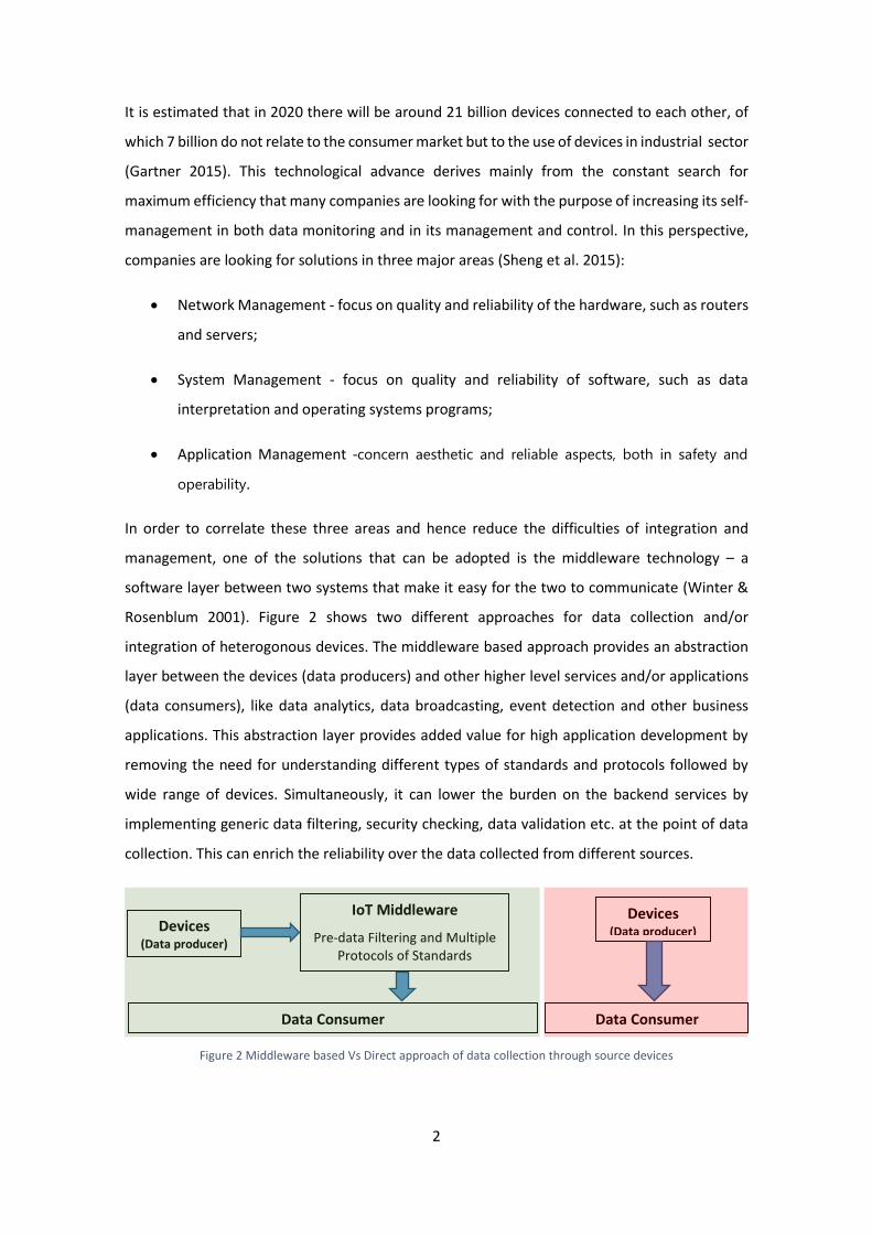
In order to correlate these three areas and hence reduce the difficulties of integration and
management, one of the solutions that can be adopted is the middleware technology – a
software layer between two systems that make it easy for the two to communicate (Winter &
Rosenblum 2001). Figure 2 shows two different approaches for data collection and/or
integration of heterogonous devices. The middleware based approach provides an abstraction
layer between the devices (data producers) and other higher level services and/or applications
(data consumers), like data analytics, data broadcasting, event detection and other business
applications. This abstraction layer provides added value for high application development by
removing the need for understanding different types of standards and protocols followed by
wide range of devices. Simultaneously, it can lower the burden on the backend services by
implementing generic data filtering, security checking, data validation etc. at the point of data
collection. This can enrich the reliability over the data collected from different sources.
Figure 2 Middleware based Vs Direct approach of data collection through source devices
IoT Middleware
Pre-data Filtering and Multiple Protocols of Standards
Devices (Data producer)
Data Consumer
Devices (Data producer)
Data Consumer

3
Essentially, this work aims to contribute to improve the methodology for data collection from
different devices by considering improvement across data access uniformity, communication
resources optimization and central management of connected devices. This project aims to
provide a solution for the integration of IoT devices with the cloud based platforms with less
effort for high end data processing and data analytics. The scope of this project also includes
Within the scope of this work it is expected it to provide solution that can provide added value
to improve production lines, increase interoperability and self-management in the
manufacturing industry through affordable technology to small and medium enterprises.
1.1. Motivation Scenario – IoT
In an interconnected Industry 4.01, ideas are much more valuable if they are embedded in an
equally innovative periphery of devices or related solutions. New impulses can come from a
multitude of sources outside the own organization, and they have to be proactively integrated
into an open innovation process. These ‘outside-in’ and ‘inside-out’ processes are enabled by
digital technologies, such as community platforms or collaborative PLM tools, connecting
knowledge resources. Collaborative engineering activities, for example with the customer, are
also greatly facilitated by the use of appropriate digital platforms and the availability of
sophisticated virtual product models (Bechtold et al. 2014). It can be clearly noted that
collection, storage and analysis of data through digital a service infrastructure incorporating a
wide range of data sources is an important feature. Figure 3 shows the high level view on value
creation through smart services by resorting to the power of IoT devices.
1 Industry 4.0 is a term applied to a group of rapid transformations in the design, manufacture,
operation and service of manufacturing systems and products (Davies 2015).

4
Figure 3 Value Creation through data collection from different IoT devices
Recent developments in IoT technologies is enabling data generated by sensor networks to be
used by business intelligence software to identify trends and patterns, and help companies to
make better decisions and become more reactive to the surrounding environment (Santucci et
al. 2012). Machine2Machine (M2M) technologies have the potential to be put to highly
innovative and practical purposes (With 2013). Current research domain involves the process of
connecting machines, equipment, software and “things” in our surroundings. “Things” will use
a unique internet protocol address, which allows for the communication with each other
without human intervention (Huang & Li 2010). At the same time, evolution of technology in the
manufacturing sector has occurred faster than the ability of companies to keep up with it
(Stöllinger et al. 2013). Thus, without having a real-time (or almost real-time) access to the shop-
floor, what was expected at the end of the production line could be different from what is
actually being produced. Besides the automated data collection and alignment to the
manufacturing plans, the synchronization and maintenance of devices deployed at different
stages of manufacturing line are often more complex (Microsoft 2009). This is partly because of
5
the diversity in the devices being used by different manufacturing plants that often have
multiple propitiatory protocols and of course also a large amount of data.
Summing up, the main motivation behind this research and development work is towards the
realization of efficient IoT middleware (as clearly marked in Figure 3) for IoT devices integration
for creation of value added enterprise services. The main target is to have a middleware solution
that can deal with heterogeneous data sources and enable data filtering closer source. Another
important requirement is also to develop a solution that is light-weight to be deployable in low-
resource computing units such as raspberry-pi. The importance of having a light-weight yet
robust IoT middleware is not only to provide one point of integration and interoperability but
also to take advantage of data pre-processing at the source by implementing functionalities for
data filtering, communication channel optimization and provide a management bridge between
cyber and physical world.
1.2. Research question
The general theme for this thesis is “Middleware based technology for data
collection in IoT systems”, which is an important research domain in the wider scope
of Internet of Things (IoT). The rational for the selected field of research has been explained in
the previous section. In order to streamline the research work it is important to define a research
question to be answered during the completion of thesis. Covering a wide number of sectors
that can be improved with the gradual introduction of IoT, it is important to define the problem
to be addressed and to which this works intends to contribute as a solution in industrial
technological advancement. The main research question formulated for this Master’s thesis is:
To ensure the research focus and targeted results, the major question can be detailed with
following sub-questions:
Q1.1: “What is the efficient mechanism for protocol adaptation to allow seamless integration of
different types of devices?”
Q1.2: “What are the suitable data filtering methodologies and algorithms that can be
implemented in the IoT middleware to enhance data pre-processing at the source with least
overhead over time?”
RQ: “Is it possible to develop scalable and interoperable middleware for
continuous data collection from real world resources?”
6
Q1.3: “What will be the impact of the middleware based methodology in the overall process of
data collection from real world resources in real-time systems?”
During the progress of this thesis, it was expected to find answers to the above mentioned
questions through necessary system implementation, validation and assessment.
1.3. Hypothesis
Based on the discussions in the previous sections that provides the motivation and formulated
research questions, one can estimate that:
The above statement is therefore the adopted as the hypothesis that will be challenged,
implemented, tested and validated during the period that will lead to the completion of the
thesis.
1.4. Work Methodology
This section focuses mainly on research-based strategy in which the dissertation and scientific
methodology that was built upon. In order to lead my thesis with the maximum rigor that it
requires, it was decided to base my scientific method of investigation in the classical
methodology (Camarinha-matos & Terminology 2016) whose phases are shown in Figure 4 and
explained in its follow-up :
“If we can develop IoT middleware, which can enable seamless integration of IoT
devices with unified implementation to detect and filter faulty data collected from
the source then efficiency of data collection from real world resources can be
improved in the IoT paradigm.”
7
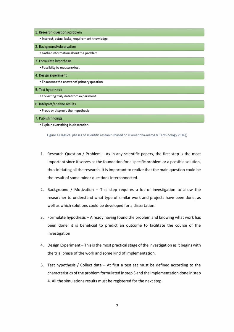
Figure 4 Classical phases of scientific research (based on (Camarinha-matos & Terminology 2016))
1. Research Question / Problem – As in any scientific papers, the first step is the most
important since it serves as the foundation for a specific problem or a possible solution,
thus initiating all the research. It is important to realize that the main question could be
the result of some minor questions interconnected.
2. Background / Motivation – This step requires a lot of investigation to allow the
researcher to understand what type of similar work and projects have been done, as
well as which solutions could be developed for a dissertation.
3. Formulate hypothesis – Already having found the problem and knowing what work has
been done, it is beneficial to predict an outcome to facilitate the course of the
investigation
4. Design Experiment – This is the most practical stage of the investigation as it begins with
the trial phase of the work and some kind of implementation.
5. Test hypothesis / Collect data – At first a test set must be defined according to the
characteristics of the problem formulated in step 3 and the implementation done in step
4. All the simulations results must be registered for the next step.

8
6. Interpret / Analyze results – At this point the results are analysed and the veracity of the
hypothesis is proved. If there were not positive results it is advisable to return to step 1.
On the other hand, when the results are achieved, it is possible to obtain some ideas for
further research.
7. Publish findings – The last phase of the suggested methodology is as important as the
first one, for the results of the investigation will be useful in future research and
contribute to the scientific community. Or, ultimately, it might become of use for the
industry.
1.5. Dissertation Outline
After the initial study that led to the question to be answered, this paper then evolves into the
following chapters:
Chapter 2 – State-Of-Art: This chapter presents the related work elements studied. The first
section explores the main definition concepts and considerations to have in data acquisition
context whilst the other two sections introduce the IoT scenarios deployed as well as the existing
middleware systems.
Chapter 3 – Hub Architecture: This chapter explains the hub on a high level overview and marks
the beginning of design experiment.
Chapter 4 – Proof of Concept Implementation: This chapter is also a stage of the design
experiment. It includes a detailed report about the practical component and an explanation on
what and why was considerate.
Chapter 5 – Testing and Hypothesis Validation: This chapter discloses the tests used to validate
the formulated hypothesis and the respective analysis to verify if the initial objectives were
achieved. It refers to the fifth and sixth stage of the work methodology. The chapter ends with
the development integration and validation with other research activities.
Chapter 6 – Conclusion and Future Work: The final chapter has an analogy between what was
studied and what was implemented, and what could be improved in future.
9
2. State-Of-Art
This chapter presents all the research undertaken and the basis for the implementation of the
formulated hypothesis. The following sections cover, in particular:
2.1. Overview - Definition of the most important concepts related to IoT paradigm.
2.2. IoT Deployment Scenarios – Different types of deployment approaches followed by
the realization of IoT ecosystem.
2.3. Middleware Solutions for IoT – A survey of existing research work in designing
middleware systems for the IoT.
2.1. Overview
The problem that this thesis proposes to investigate is part of a vast subject, covering several
technical concepts. Therefore, it is important to provide an explicit definition and build the
background on which the research will be based. In order to formulate the foundation for this
thesis. The following sub-sections provide the state of the art on different aspects of IoT that
were taken into account for development and research in the scope of this dissertation.
2.1.1. Internet of Things
According to (IERC 2010), IoT is “A dynamic global network infrastructure with self-configuring
capabilities based on standard and interoperable communication protocols where physical and
virtual “things” have identities, physical attributes, and virtual personalities and use intelligent
interfaces, and are seamlessly integrated into the information network.”
It is a concept and a paradigm that considers pervasive presence around us in the environment
of a variety of things/objects/devices, which through wireless and wired connections and unique
addressing schemes are able to interact with each other and cooperate with other
things/objects/devices to create new applications/services and reach common goals (Atzori et
al. 2010).
According to (Bradley et al. 2013) the five main factors increasing the values associated to the
IoT are:
10
Increasing the return on research and innovation investments, reducing time to market,
creating new business models and opportunities;
Increasing the lifetime of customer and adding more customers;
Improve utility services such as supply chain and logistics, to a new and more efficient
level;
Improve business process with the expense on goods reduced;
Increasing the employee productivity and efficiency.
The IoT awareness affects a large number of areas and interested parties. The associated values
at manufacture industry, the main target of this thesis, benefits in areas like machine auto-
diagnosis and assets control through sensors installed in machines allowing a faster response to
detected problems and remote monitoring of elements such as temperature, raw materials and
humidity, adjusting them automatically. The IoT potential is analysed in (Joseph Bradley, Joel
Barbier 2013) with examples of critical improvements such as reduction of materials, energy and
costs of automated tools, which is less expensive to manufacture and implement. The potential
of IoT extends also to the automated management, detection and self-healing of the machinery,
available resources, product quality and other services. Lastly, increased sales from real-time
market assessments and reactions, location-based selling and improve coordination with other
products and services (two-sided markets).
2.1.2. Middleware for Data Acquisition
In order to develop a data collection system from RW resources, there are generic features that
have been identified:
Provide an infrastructure to capture data from IoT sources.
Provide an infrastructure that is modular and independent of the devices geographic
location and functionality.
Techniques of filtering data to control the flux of data coming into the platform.
Security of communication channels (where authenticated data should flow).
Support to different communication protocols should be available;

11
In IoT context, the objective of having a middleware platform is to present a unified model to
interact with devices as it provides an abstract layer interposed between the IT infrastructure
and the applications (Chaqfeh & Mohamed 2012). Therefore, the problems concerning with
interaction of devices are described in Table 1, according with (Fersi 2015):
Table 1 Five main functionalities handled by an IoT middleware
Interoperation
Share information through diverse domains
of applications using diverse communication
interfaces. Divided in: Network, Syntactic
and Semantic.
Context Detection
Characterize the situation of an entity
(person, place or object) relevant to the
interaction between a user and an
application, including the user and
applications themselves.
Device discovery and management
Enables any device in the IoT network to
detect all its neighbouring devices and make
its presence known to each neighbour in the
network.
Security and privacy
Data confidentiality - refers to protecting the
data from any kind of unauthorised
disclosure; Data integrity - refers to
protecting data from being lost, destroyed,
corrupted or modified; Data availability -
refers to the ability to guarantee that the
collected data can be used in dedicated time.
Managing Data Volume Finding, fetching and transfer raw data in
order to process and indexing it allowing a
more efficient querying result.
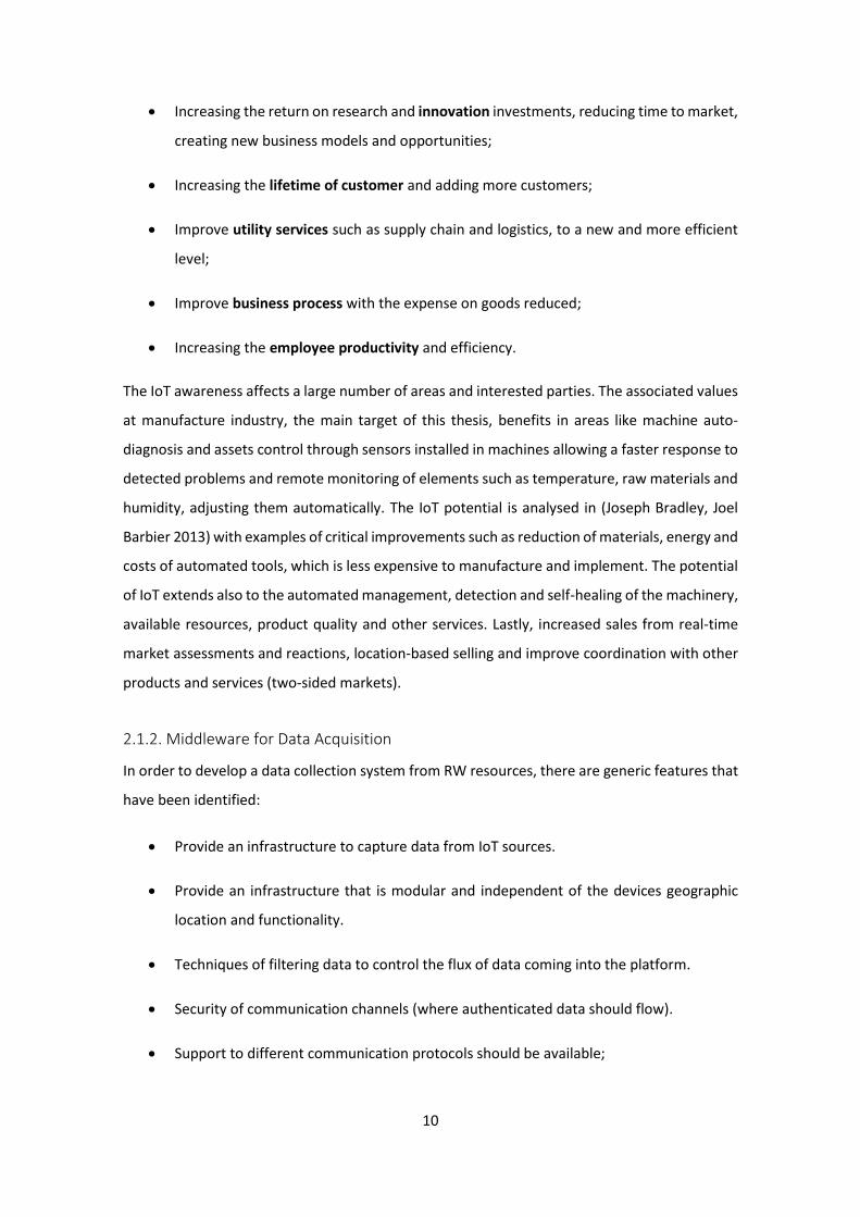
To summarize, an IoT middleware is a true end-to-end platform that enables connectivity
between “things” or devices constituted by eight architectural building blocks, as shown in
Figure 5.
12
Figure 5 The eight components of an IoT Application Enablement Platform (Padraig Scully 2016)
2.1.3. Data Collection from Sensors – Context Acquisition
To understand the key considerations and challenges that data collection can bring, it is
necessary to clarify the meaning of data sources. Sensors are hardware components that
measure environmental information such as temperature, humidity, location, state of the
machine, processing time and more that will be transformed into a digital signal. This
information is accessed by software programs to help with some task (Microsoft 2016). In this
way, an important consideration in a data collection system is the context-aware computing in
IoT paradigm.
In the past, most of the proposed solutions collected data from a limited number of physical
(hardware) and virtual (software) sensors. In these situations, collecting and analysing sensor
data from all sources was made possible and feasible due to limited numbers. On the other
hand, nowadays, with the progression in sensor hardware technology and cheap materials,
sensors are expected to be attached to all the objects around us and connected to the internet,
which means it is not feasible to process all the data collected by those sensors. Consequently,
context-awareness will play a critical role in deciding what data needs to be processed, which
implies that understanding sensor data is one of the main challenges that the IoT will face.

13
Context management has become an essential functionality in software systems. Data move
from phase to phase, from the place where it is generated to where it is consumed, creating a
data life cycle. Figure 6 consider the movement of context in context-aware systems.
Figure 6 Four essential steps in context management systems and middleware solutions (Perera et al. 2014)
The definition of Context-Awareness is not strict due to its abstract nature. Different authors
propose different definitions, notwithstanding, this thesis accepts the meaning proposed by
Dey, due to the fact it is defined when it is applied in a system. Therefore, according with (Abowd
et al. 1999): “A system is context-aware if it uses context to provide relevant information and/or
services to the user, where relevancy depends on the user’s task.”
The focus that the concept context-aware will have in this thesis is related with context
acquisition, since we are handling with pre-filtering data (Data Processing) and physical sensors
(Data Source Support), as depicted in Figure 7.
Figure 7 Conceptual Framework (features that need to be supported by ideal context-aware acquisition IoT middleware solution) (based on (Perera et al. 2014))
There are five techniques that need to be considered when we want to acquire context while
developing context-aware middleware solutions:
Responsibility
14
According with (Pietschmann et al. 2008), there are two different methods:
Pull - The software component which is responsible for acquiring sensor data from
sensors make a request from the sensor hardware periodically or instantly to acquire
data.
Push - The physical or virtual sensor pushes data to the software component which is
responsible to acquiring sensor data periodically or instantly.
Frequency
Making a parallelism with real world, the frequency technique is based on two different event
types:
Instant - The events do not span across certain amounts of time. Open a door, switch on
a light are some types of instant events. In order to detect this type of event, sensor
data needs to be acquired when the event occurs.
Interval - These events span a certain period of time. For example, raining and seasons
of the year are some interval events. In order to detect this type of event, sensor data
needs to be acquired periodically.
Source
According with (Chen et al. 2004), acquiring information must have taken into account the
source that can be categorized into three different categories:
Directly from sensor hardware - Context is directly acquired from the sensor by
communicating with the sensor hardware and related APIs. This method is typically used
to retrieve data from sensors attached locally. Despite the growing use of devices that
communicate wirelessly, in IoT paradigm, most devices and sensors today require some
amount of driver support and can be connected via USB, COM, or serial ports.
Through a middleware infrastructure - Sensor data is acquired by middleware solutions.
The applications can retrieve sensor data from the middleware and not from the sensor
hardware directly.
15
Context servers - Context is acquired from several other context storages via different
mechanisms such as web service calls. This mechanism is useful when the hosting device
of the context-aware application has limited computing resources.
Sensor Types
There are different types of sensors that can be employed to acquire context and can be
divided into three categories (Indulska & Sutton 2003):
Software sensors – A web service is a perfect example of this type of sensor. The idea is
to produce more meaningful information with the combination of physical sensors and
virtual sensors.
Virtual sensors – This type of sensors do not have a physical presence. They aggregate
data from many sources and publish it as sensor data (e.g. calendar, contact number
directory and chat applications).
Physical sensors – Since IoT solutions needs to understand the physical world, this type
of sensor is very important in data acquisition process due to the fact that is the only
one that generate sensor data by themselves. For instance, measuring the temperature
or humidity of a given space is made using temperature sensors or humidity,
respectively. They are less meaningful, trivial, and vulnerable to small changes.
Acquisition Process
Finally, the acquisition process is a very important technique in the acquire context. In general,
there are three different categories:
Sense - The data is sensed through sensors (e.g. retrieve temperature from a sensor,
retrieve appointments details from a calendar).
Derive - The information is generated by performing computational operations on
sensor data (e.g. calculate distance between two sensors using GPS coordinates).
Manually provided - Users provide context information manually via predefined settings
options such as preferences.
The main issue when we want to collect data is how to obtain it in a useful way. To do so, it is
important to identify the key characteristics of data, knowing how to measure/collect them and
16
what to do with the data collected. The overall objective of data collection is helping
stakeholders of different levels to make decisions based on true indicators of real-time situations
as depicted in Figure 8.
Figure 8 Difference between a good and a bad analysis of data collected
From the moment that data is sensed by devices such as a wireless sensor node, up to the
moment that reach the backend system, there are many aspects that must be taken into
consideration. In the future, IoT is expected to be an interconnection of networked embedded
devices (Karnouskos et al. 2011) that will require to build systems with Cooperating Objects (CO).
According to (Marrón et al. 2009), CO are computing devices with the ability to communicate,
cooperate and organize themselves autonomously into networks to achieve a common task.
In conclusion, context is responsible for characterizing the situation of an entity, where an entity
can be person, place, or object relevant to the interaction between a user and an application,
including the user and applications themselves. IoT-middleware must be context aware for
working into smart environments. Context awareness can be achieved by context detection and
context processing. Context detection collects data and identifies the factors that have
significant impacts on the response. Context processing extracts the context data, processes it
and performs or takes decision based on that. A knowledge database is required for setting up
a closed feedback path between these blocks to evaluate the effectiveness of context-aware
systems and make some possible improvements.
However, this thesis proposes a middleware without persistent data storage. The knowledge of
database is inexistent, so in this context, the data will go through, a pre-processing phase at the
hub, before the main processing is made in the Cloud. Since, context-detection is a resource
demanding task, the core implementation of this functionality is to be performed at the cloud
(outside the scope of this thesis). But, preliminary context-detection can be implemented in the
IoT-middleware that can be used for the data source identification, data type assertion and
preliminary validation of the collected data based o on the sensor properties. These preliminary
functionality of context-acquisition has been implemented in the scope of the thesis that can
form a base for the development of context-aware applications.
Data indicate that are a problem This might have a problem
17
2.1.4. IoT Protocols
Communication protocols are formal descriptions of digital message formats and defined rules
that includes: packet size, transmission speed, handshaking and synchronization techniques,
error correction types, address mapping, acknowledgment processes, flow control, packet
sequence controls, routing and address formatting (Techopedia 2016b). They are implemented
in hardware (communication protocols) and software (message protocols) and used to exchange
messages between computing systems.
Messaging Protocols
In Internet of Things, the communication is made by three different computing systems:
Device to Device – Example: DDS
Device to Server – Examples: MQTT, REST/HTTP, XMPP, CoAP
Server to Server – Example: AMQP
Each system has different types of protocols (with different message formats and defined rules)
to interact. The examples given above are not restricted to the computing system which they
belong, however, the protocols were grouped according the frequency of their utilization in the
computing system. Considering that the concept of the middleware implemented in this thesis
is based on the interaction between the device (sensors aggregated in a single device) and the
cloud, this sub-section explains with more detail the software protocols of Device to Server
system, resorting to examples which are summarized in Table 2. An example of the
communication between the others computing a system is also included.
DDS - While interfacing with the IT infrastructure is supported, DDS’s main purpose is to connect
devices to other devices. As explained in (Esposito et al. 2008), architecture of DDS defines two
layers: Data-Centric Publish-Subscribe (DCPS) and Data-Local Reconstruction Layer (DLRL). DCPS
layer is responsible for delivering information to the end destinations (subscribers). DLRL
represents, on the other hand, optional layer which serves as the bridge/interface to the DCPS
functionalities (which is constituted by five entities to manage data flow: Publisher, Data Writer,
Data Reader, Subscriber and Topic).
DDS can efficiently deliver millions of messages per second simultaneous to various receivers.
Devices demand data very differently (faster) than the IT infrastructure demands data. “Real
time” is often measured in microseconds. Devices need to communicate with many other

18
devices in complex ways, so TCP’s simple and reliable point-to-point streams are far too
restrictive. Instead, DDS offers detailed quality-of-service (QoS) control, multicast, configurable
reliability, and pervasive redundancy. DDS offers powerful ways to filter and select exactly which
data goes where, and “where” can be thousands of simultaneous destinations. DDS implements
direct device-to-device “bus” communication with a relational data model.
MQTT – This protocol targets device data collection and communicating it to servers. As its name
states, its main purpose is telemetry, or remote monitoring. Its goal is to collect data from many
devices and transport that data to the IT infrastructure. It targets large networks of small devices
that need to be monitored or controlled from the cloud. Since it has a clear, compelling single
application, MQTT is simple, offering few control options. It also doesn’t need to be particularly
fast. In this context, “real time” is typically measured in seconds. The protocol works on top of
TCP, which provides a simple, reliable stream that don’t lose data.
MQTT consists of three key components: subscriber, publisher, and broker. An interested device
can register as a subscriber for the specific content in order to be informed by the central point
(broker) every time when a publisher disseminates information of interest (Locke 2010). In this
architecture, the publisher stands for the meter/sensor sending data to MQTT broker. Secure
communication between all parts is achieved by verifying the authorization of publishers and
subscribers on the side of broker (Stanford-Clark & Truong 2013).
From the M2M communication point of view, the main disadvantage of MQTT is the fact that
end devices may go to sleep state for a limited time period only (a lot of sensors/smart meters
send the data once per few hours and therefore MQTT is not a suitable communication protocol
for these power-constrained devices).
CoAP - In contrast to REST, CoAP is utilizing lightweight UDP as transport protocol, making it
more suitable for the IoT domain because it is possible to build sufficiently basic error checking
and verification for UDP to make sure that messages arrived without the significant
communication overhead in case of TCP. However, CoAP was designed together with REST
functionality; therefore, conversion between these two protocols has to be implemented in
communication chain.
According with (Gligoric et al. 2012), CoAP can be divided into two sublayers:
- Messaging Sublayer - It detects duplications and based on that provides reliable
communication even over the UDP transport protocol using the exponential backoff
19
(multiplicative decrease of the rate of data transmission, in order to gradually establish
an acceptable data rate); this is a necessary technique since UDP does not include error
recovery mechanism;
- Request/Response Sublayer - It handles REST communication between individual nodes.
This protocol utilizes four message types: confirmable, non-confirmable, reset, and
acknowledgment. Reliability of CoAP is achieved by using confirmable and non-
confirmable messages. Similarly, HTTP utilizes methods such as GET, PUT, POST, and
DELETE to perform Create, Retrieve, Update, and Delete operations. A typical length of
CoAP message can vary between 10 and 20 bytes (Colitti et al. 2011), this means that
CoAP may be unsuitable for some domains of IoT.
REST/HTTP – This protocol follows the principal that every physical object and/or logical entity
is a resource that has a particular state that can be “manipulated”. A resource that is accessible
via HTTP URI gives access to its data via GET and accepts inputs via PUT. REST aims on minimizing
latency and network communication, while at the same time maximizing the independence and
scalability of component implementations (Fielding & Taylor 2002). The effort needed to
develop applications, especially in the IoT domain, can be greatly reduced since REST adopts a
much lighter tool chain than other service oriented architectures, making this message protocol
massively scalable, as explained in “M2M Communications: A Systems Approach” by D.
Boswarthick, O.Elloumi and O. Hersent, Wiley, 2012. Data communication is generally initiated
by the Device over HTTP GET/POST Request. Devices will be sleeping all the time unless during
communication.
It is a good option for IoT device (data source) to IoT middleware to communicate in the local
network. In order for IoT devices and IoT middleware to communicate via HTTP, we need to
resolve some issues. The solemn problem that one need to work around is that HTTP is a
challenge-response protocol. This means the device will either have to keep polling the server
for new updates, or use long polling, or use websocket. The cost of communication has dipped
significantly so the overheads attached to HTTP don’t pose a significant constraint since
Transport Layer Security [TLS] can be obtained through HTTPS. In the scope of this thesis,
HTTP/REST has been identified as a very useful protocol for communication between the IoT
middleware and data consumers but not a very suitable protocol for communication between
devices and middleware.
20
XMPP - A protocol suited to connect devices to people, a special case of the D2S pattern. It was
developed for instant messaging to connect people via text messages. XMPP uses the XML text
format as its native type, making person-to-person communications natural. It connects clients
and servers using the XML called stanza which divide the code into three components: message,
presence and info/query (Jones 2009). Messages in stanza identify the source and destination
address, types, and IDs of XMPP entities that provide PUSH method for retrieving data. The
presence stanza notifies end users of the status updates. Finally, the iq stanza does the pairing
between message senders and receivers. The possible disadvantage of XMPP is text-based
communication using XML. This leads to higher network load (overhead). Ergo there is a possible
solution to this problem: XML streams using EXI (Waher & Doi 2014).
In the IoT context, XMPP offers an easy way to address a device. This comes especially handy if
that data is going between distant, mostly unrelated points, just like the person-to-person case.
It’s not designed to be fast. In fact, most implementations use polling, or checking for updates
only on demand. “Real time” to XMPP is on human scales, measured in seconds. Its strengths in
addressing security, and scalability make it ideal for consumer-oriented IoT applications.
AMQP - A queuing system designed to connect servers to each other. Communications from the
publishers to exchanges and from queues to subscribers use TCP, which provides strictly reliable
point-to-point connection. AMQP is realized by two key components (Fernandes et al. 2013):
- Exchanges: They are used for routing messages to appropriate queues. Routing
(between exchanges and queues) is based on predefined rules/requirements;
- Message Queues: They are stored in message queues before sending to end destination
(receiver).
Following that, two types of messages are defined in AMQP, bare messages (at the sender's side,
includes properties, application properties and application data) and annotated messages (at
the receiver side, includes header, delivery and message annotations, footer and the bare
message information).
AMQP is mostly used in business messaging because it focuses in tracking all messages and
ensuring each is delivered as intended, regardless of failures or reboots. It usually defines
“devices” as mobile handsets communicating with back-office data centers. In the IoT context,
AMQP is most appropriate for the control plane or server-based analysis functions.
21
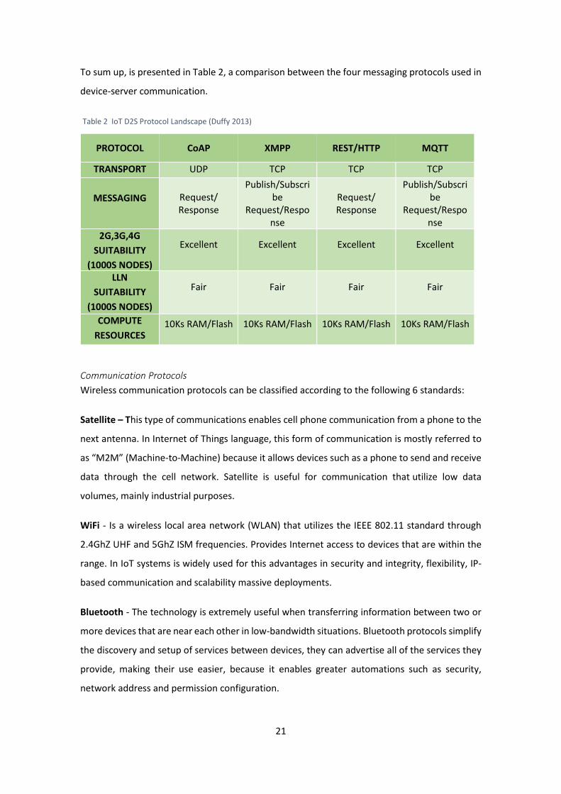
To sum up, is presented in Table 2, a comparison between the four messaging protocols used in
device-server communication.
Table 2 IoT D2S Protocol Landscape (Duffy 2013)
PROTOCOL CoAP XMPP REST/HTTP MQTT
TRANSPORT UDP TCP TCP TCP
MESSAGING Request/ Response
Publish/Subscribe
Request/Response
Request/ Response
Publish/Subscribe
Request/Response
2G,3G,4G
SUITABILITY
(1000S NODES)
Excellent Excellent Excellent Excellent
LLN
SUITABILITY
(1000S NODES)
Fair Fair Fair Fair
COMPUTE
RESOURCES 10Ks RAM/Flash 10Ks RAM/Flash 10Ks RAM/Flash 10Ks RAM/Flash
Communication Protocols
Wireless communication protocols can be classified according to the following 6 standards:
Satellite – This type of communications enables cell phone communication from a phone to the
next antenna. In Internet of Things language, this form of communication is mostly referred to
as “M2M” (Machine-to-Machine) because it allows devices such as a phone to send and receive
data through the cell network. Satellite is useful for communication that utilize low data
volumes, mainly industrial purposes.
WiFi - Is a wireless local area network (WLAN) that utilizes the IEEE 802.11 standard through
2.4GhZ UHF and 5GhZ ISM frequencies. Provides Internet access to devices that are within the
range. In IoT systems is widely used for this advantages in security and integrity, flexibility, IP-
based communication and scalability massive deployments.
Bluetooth - The technology is extremely useful when transferring information between two or
more devices that are near each other in low-bandwidth situations. Bluetooth protocols simplify
the discovery and setup of services between devices, they can advertise all of the services they
provide, making their use easier, because it enables greater automations such as security,
network address and permission configuration.

22
Radio Frequency communications are probably the easiest form of communications between
devices. Protocols like ZigBee or ZWave use a low-power RF radio embedded or retrofitted into
electronic devices and systems. In IoT systems this type of communication has significant
advantages in low-power operation, high security and scalability.
RFID is the wireless use of electromagnetic fields to identify objects. Usually is installed an active
reader, or reading tags that contain a stored information mostly authentication replies. It is also
called an Active Reader Passive Tag (ARPT) system. An Active Reader Active Tag (ARAT) system
uses active tags awoken with an interrogator signal from the active reader. The main advantage
is the hundreds of applications which can be used.
NFC uses electromagnetic induction between two loop antennas located within each other near
field, effectively forming an air-core transformer. There are two modes: Passive - The initiator
device provides a carrier field and the target device answers by modulating the existing field. In
this mode, the target device may draw its operating power from the initiator-provided
electromagnetic field, thus making the target device a transponder; Active - Both initiator and
target device communicate by alternately generating their own fields. A device deactivates its
RF field while it is waiting for data. In this mode, both devices typically have power supplies. The
main advantages are related with data security at multiple levels, the ability to connect the
unconnected, easy network access and data sharing.
2.1.5. Data Pre-processing
Data pre-processing is often neglected but important step in the data collection process. If there
is irrelevant and redundant information present or noisy and unreliable data then events and
trends detection at application layer is made more difficult. This process also includes a
technique that involves transforming raw data into an understandable format (the format can
be defined by the hub or requesting data consumer). Real-world data is often incomplete,
inconsistent, and/or lacking in certain behaviours or trends, and is likely to contain many errors
(Techopedia 2016a).
In a real world data analytics situation, it is common to find several data pre-processing steps
before using them in the application layer, mainly due to varying nature of the available data.
The methodology for data pre-processing has been widely adapted in the domain of data mining,
which can provide important background for data filtering in IoT scenario. In chapter 3 of (J.Han,
J.Pei, M.Kamber 2012), is a detailed description of the steps that could be done prior to the main

23
processing in order to have a better data quality which is defined in terms of accuracy,
completeness, consistency, timeliness, believability and interpretability. The main steps and
techniques are:
Data Cleaning – This method works to “clean” the data by filling in missing values, smoothing
noisy data, identifying or removing outliers and resolving inconsistencies. Each step has its own
methods:
Missing values – If it is noted that there are many tuples that have not recorded value for several
attributes, then the missing values can be filled in for the attribute by various techniques:
Ignore the tuple – This is usually done when the class label is missing. However, it is poor
technique when the percentage of missing value per attribute varies considerably.
Fill in the missing value manually – In general, this approach is time-consuming and may
not be feasible given a large data set with many missing values.
Use a global constant to fill in the missing values – It is a simple technique that replace
all the missing attribute values by the same constant.
Use the most probable value to fill in the missing value – This may be determined with
inference-based tools using a Bayesian formalism or decision tree induction.
Noisy Data – It is a random error or variance in a measured variable and it is resolved with some
data smoothing techniques:
Binning methods – Smooth a sorted data value by consulting the values around it,
performing a local smoothing.
Clustering – Similar values are organized into groups or clusters
Combined computer and human inspection – Outliers may be identified through a
combination of computer and human inspection. Patterns whose surprise content is
above a threshold are output to a list. A human can then sort through the patterns in
the list to identify the actual garbage ones. This is faster than having to manually search
through the entire database.

24
Regression – Involves finding the best line to fit two variables, so that one variable can
be used to predict the other. Using regression to find a mathematical equation to fit the
data helps smooth out the noise.
Inconsistent Data – In some transactions of data inconsistencies might occur that could be
corrected manually using external references. For example, known functional dependencies
between attributes can be used to find values contradicting the functional constraints.
Data Integration – Involves combining data from multiple sources into a coherent data store as
in data warehousing. This type of method requires an entity identification of each device, before
the integration of data, in order to know the data source and henceforth determination of the
nature of the data. Typically, databases have metadata (data about the data) that can be used
to help avoid errors in this step.
Data Transformation - This method involves consolidate appropriate data for mining. It can
involve four techniques:
Normalization – The attribute data are scaled so as to fall within a small specified range.
Smoothing – Remove noise from data by clustering, binning or regression.
Aggregation – Aggregated operations are applied to the data in order to construct a data
cube for analysis of the data at multiple granularities.
Concept hierarchy generation – Low level data (raw) is replaced by higher level concepts
through the use of concept hierarchies. Examples: transforming an integer that refers
to someone’s age into an attribute like young, middle-aged or senior; transforming the
name of a street in a city or a country.
Data Reduction – It is used to make the data analysis less complex and feasible in terms of time.
This method has been helpful in analysing reduced representation of the dataset without
compromising the integrity of the original data and yet producing the quality knowledge. The
main strategies of this pre-processing method are:
Aggregation – Similar to the aggregation technique of data transformation
Dimension reduction – Removed the amount of data if there are irrelevant, weakly
relevant or redundant attributes.

25
Data Compression – Encoding mechanisms are used to reduce the data set size.
Numerosity reduction - Smaller data representations by histograms, sampling or other
parametric models reducing the amount of data values.
Concept hierarchy generation - Similar to the aggregation technique of data
transformation
To sum-up, data pre-processing refers to the cleansing and transformation of the data in the
early stage of data collection and before being pushed towards the data consumers and/or
persistence storage. In an IoT scenario, it is a key functionality to guarantee the reliability of the
data being collected. At the same time devices can generate huge amount of data to be
processed, so applying techniques to process only key data, will allow the system to improve
one’s efficiency and performance. Those techniques are introduced by the definition of a set of
rules, generally done by a user with administrative role.
2.2. IoT Deployment Scenarios
The growing popularity of the Internet and the availability of powerful computers and high-
speed networks as low-cost commodity components are changing the way we do computing.
This section describes the four possible deployment scenarios in IoT architecture for data
collection and their different applications in different purposes and domains.
In presenting the deployment scenarios, different considerations are made in the way data
sources and data consumers are integrated to form an IoT ecosystem. Firstly, is presented the
peer-to-peer model, which considers building the network among different data sources and
consumers with their own communication infrastructure. While, the others deployment models
make use of external communication (and/or processing) infrastructure such as cloud to form
the overall IoT ecosystem. Among these the first one is an architecture that lacks middleware
and each of the data sources utilize their own communication resources and other higher level
intelligence such as storage, processing, interoperability, etc. are all in the cloud. Subsequently,
it is shown two types of architectures that use software abstraction layer - middleware -
between devices and the cloud in different ways. In the first approach, the data collection
system has several middleware that share various types of processing capacity, so that in the
final process, the system achieves a particular purpose. In the second approach, corresponding

26
to the architecture implemented in this thesis, each system has a middleware that has all the
features that are required without being dependent on others.
2.2.1. Peer-to-Peer Devices
In general, in a P2P system every node acts as both a client and a server, providing part of the
system resources, in a non-hierarchical scenario. This means that no master-slave relationship
exists among the peers, and there is no central server responsible to store and administrate
exists because there does not exist any peer machine with a global view of P2P system. However,
with the advances in peer-to-peer technology began to appear slightly different architectures of
traditional, as depicted in Figure 9. The complexity is not in the machine (simply client computers
connected to the Internet) nor in the communication since all machines act autonomously to
join or leave system freely (Kahanwal & Pal Singh 2012), so the main issue is in the architecture
of the distributed control system, which can be structured or unstructured (Doulkeridis et al.
2007):
Structured – A hash function is used in order to couple keys with objects. Then a
distributed hash table (DHT) is used to route key-based queries efficiently to peers that
hold the relevant objects. In this way object access is guaranteed within a bounded
number of hops.
Unstructured - Each peer maintains a limited number of connections (also called links)
to other neighbouring peers in the network. Searching in an unstructured P2P
environment usually leads to either flooding queries in the network using a time-to-live
(TTL) or query forwarding based on constructed routing indices that give a direction for
the search.
Hybrid Peer-to-Peer System
The major shortcoming of purely peer-to-peer systems is scalability issues and the poor
performance during query processing. Therefore, except of purely decentralized architectures,
also hybrid systems were proposed which can be divided into (Doulkeridis et al. 2007):
Centralized indexing systems - there is a central server facilitating the interaction
between peers and a centralized index is built at this specialized peer. The centralized
index keeps information about the data stored at each peer, together with the peer
identifier. Therefore, centralized indices are efficient during query processing; a single

27
message is required to determine which peer stores relevant information. Notice that
the actual sharing of information between peers is established by communication
between the peers, without interaction with the central server. Despite the efficiency
during query processing, centralized indices have a major drawback, namely they
constitute a” single point of failure”. Moreover, the centralized index may become a
bottleneck for the system, especially in the case of a large P2P network.
Decentralized indexing systems – Also known by Superpeers, this architecture tackle the
scaling and the “single-point-of-failure” problems of centralized approaches, while
exploiting the advantages of the completely distributed approach, where each peer
builds and maintains an index over its own files. These systems are similar to purely
decentralized systems (if only the Superpeers are considered), but some of the peers
have a more important role, and are responsible to maintain the information available
at their associated peers and facilitate the interaction between peers. Super-peer
networks take advantage of the heterogeneity of peer capabilities (e.g., bandwidth,
processing power) and peer application in a P2P network, once can have different roles
by nature, similar to the case of file-sharing, where some machines are registered as
dedicated servers to the system, while others are plain personal computers that mostly
request information. Furthermore, in order to respect peers’ autonomy, any approach
should not rely on arbitrary data movement; hence each peer joining the network
should autonomously store its own data. Therefore, super-peer architecture appears
particularly suitable for applications that require efficient performance for advanced
query operators; hence we model our distributed system as a super-peer network. The
overall objective is for a set of cooperative computers to collectively provide enhanced
processing facilities, aiming at overcoming the limitations of centralized settings, for
example extremely high computational and storage load.

28
Figure 9 Three different approaches in an IoT Peer-to-Peer scenario (Hota 2013)
2.2.2. Devices to Service Providers
In this type of scenario, there is a direct interaction between the sensor nodes and application
layer. Without using intermediary devices that regulate, transform or interpret the data before
integration into the business processes. The main objective of this class of data collection system
is, in general, focus data intelligence in a single infrastructure using “dumb” sensors, constituted
only by a layer hardware responsible between the communication of devices and the provided
services.
Making an analogy to the distributed computing systems, this scenario is similar to the idea of
cloud computing in IoT systems which is explained carefully and detailed in (Buyya et al. 2011).
The aim of this scenario is to concentrate computation and storage in large-scale data centres
by transforming everything as a service, such as hardware virtualization (decouples applications
from the underlying hardware) which mediate access between the physical resources and the
software layer as highlighted in Figure 10. The biggest advantage is the independence that
virtual resources have from each other and from the physical hardware (for instance, in case of
failure or capacity constraints), creating an abstract architecture easy to access for the
consumer.

29
Figure 10 Data flow between devices and Cloud (Brown 2014)
This data centre infrastructure can be shared by several customers without compromising the
privacy and security of each one, providing a pool of computing resources to serve multiple
consumers using a multi-tenant model as illustrated in Figure 11. The idea is to provide to the
customers the capability of request, customize, pay and use services (which are available over
the network and accessed through standard mechanisms by different platforms such as laptops
and mobile phones), automatically, without requiring interaction with providers or any
intervention of human operators (Mell et al. 2009). Although, the access of shared services is
cost-effective, it causes performance degradation and performance unpredictability. To close
this gap, it is possible to make this architecture auto scaling. In case of peak demand more virtual
machines can be quickly provisioned (on two or more physical machines) or rapidly released
when the work load decreases.
Figure 11 Interaction between the end-user and Cloud software services (TheOpenGroup 2013)
This system brings many advantages to IT companies, is based on the concept of utility
computing where consumers pay-per-use computing services (Gong et al. 2010), allowing to

30
deploy specialized virtual appliances in order to consider the great disparity between user needs
in a multi-tenant environment, similar to what is being done for utilities such as Electricity, Gas,
Water and Telecommunication. Furthermore, Cloud Computing brought cost savings for
consumers (eliminating the total cost of the entire infrastructure by sharing the cost of
electricity, hardware engineers, facilities management, system administration, fire protection,
insurance, etc) (Buyya et al. 2011).
2.2.3. Devices to Middleware to Service Providers
In computer systems distributed in IoT, this scenario has emerged in parallel with the concept
of Fog Computing. The aim of this architecture is to face the massive quantities of information
at any time, in any place and with any device that is extremely dispersed and produced by and
about people, things, and their interactions (Hajibaba & Gorgin 2014). In fact, big data, real time
analytics and localization was the main reasons to businesses requiring a new approach to
distribute all data and place it closer to the end-user, eliminate service latency, improve QoS and
remove other possible obstacles connected with data transfer (Aazam & Huh 2015). Figure 12
shows an example of an IoT architecture divided by layers whose middleware corresponds to
the gateway layer.
Figure 12 Example of an IoT Architecture with middleware (Harbinger Systems 2015)
The purpose of a middleware in a data collection system is not to remove some features of
service providers, but to add more functionality to reduce the complexity of some of those
services in order to reduce the amount of time, processing or storage in the Cloud. Middleware
is software that provides services to software applications beyond those available from the

31
Cloud providing common programming abstraction and infrastructure for distributed
applications. In generally, The Fog is located bellow the Cloud and his purpose is targets the
services, compute, storage, workloads, applications and big data with widely and truly
distributed systems (Aazam & Huh 2014).
Figure 13 Fog between the edge and the cloud (Amaravadhi 2015)
As depicted in Figure 13, it is an additional layer which develops the concept of Cloud services
bringing network resources near underlying networks (Hajibaba & Gorgin 2014; Aazam & Huh
2014). Services are hosted at the network edge or even end devices such as set-top-boxes or
access points in order to enabling creation of refined, better and optimize applications or
services. The creation of various edge points is turning data centre into a distributed Cloud
platform for different types of users, bringing the computing from the core to the edge (Hajibaba
& Gorgin 2014).
With the rise of interconnected devices and business scenarios around networked machines,
the infrastructure to maintain all things connected is being more complex. The aim of this
scenario is to have hierarchical organization from the core to the edges to support low latency
and scalability. This “extra layer” has more proximity of the data to the consumer extending the
Cloud services closer to mobile users (Bonomi et al. 2012). Another important characteristic is
the dense geographical distribution which is the reason of existing a large number of nodes, that
allows better support for location-based services as well as faster analysis of data in real-time
(Buest 2013). Associated to the large number of nodes with a wide variety of environments
appears the interoperability problem once the heterogeneity of devices at different levels
require certain services and applications provided by this scenario. Besides that, middleware is
used to be reliable and available, reducing application development and maintenance efforts
and also to provide a distributed computing.
32
Centralized or Distributed Middleware
In contrast of Cloud’s centralization, a middleware (layer located in the fog or local
infrastructure) provides localization, once the server belongs to the same network as the end-
users and have knowledge of each one becoming that information an advantage to customize
the optimization (Zhu et al. 2013). This scenario supports better real-time interactions,
actionable analytics, processing and filtering data by services implemented in the middleware,
and then pushes to the Cloud. In this way, user data is isolated from the Cloud and from there
administrators are able to tie-in analytics, security or other services directly into their cloud
model (Kleyman 2013).
The main difference between a centralized and a distributed middleware is the services provided
by them. In a decentralized system, the idea of having multiple middleware with different kinds
of capabilities (data filtering, complex event processing, secure data validation and trust
mechanism) is much more appreciate in terms of complexity and scalability. Moreover, the
functionalities and heterogeneity of the devices connected in the system could be enormous,
therefore, with this scenario it is possible to minimize the processing of a middleware once it
will be used only for the devices that require that particular service. However, in a centralized
IoT system that intends to have a specific purpose, a single middleware could be a better
solution once their variety of applications could be work together without losing functionality.
Depending on the purpose that an IoT system has, different solutions could be better than
others. Both of the sub-scenarios (single and distributed middleware) are being discussed in this
sub-chapter have the same goal:
Hide the heterogeneity of the shop floor resources;
Provide an independence location of the resources;
Help integrate legacy facilities;
Aggregate common functionalities needed by many applications.
Although they have the same objective, their use depends mainly to:
The use that devices give of the applications presents in the hub;
The processing capacity where the hub is implemented;

33
The complexity and scalability that we want to implement in the system, having in
consideration further modifications.
In Figure 14 is illustrated both scenarios where in middleware 1 has data filtering capability,
while middleware 2 has capability for complex event processing and middleware 3 has secure
data validation and trust mechanism, and the functionalities are distributed among middleware
to achieve an overall full functional system. On the other hand, a single middleware is
independent from each other and every necessary functionality needs to be implemented in
each of them.
Figure 14 IoT middleware for data collection - Single or Distributed
2.3. Middleware Solutions for Internet of Things
As the IoT encompass a wide area of applications, middleware layers also have different domains
which might be covered and will be explained in the first sub-section. Subsequently, the current
solutions in the context of IoT will be presented. Finally, an analysis on the major challenges in
implementing middleware systems assessing their strengths and weaknesses is explained.
2.3.1. Domain
The middleware solutions can be categorized according to the involved domains into three
major categories (Chaqfeh & Mohamed 2012):
Hub with Several Middleware
Middleware 1
Filtering
Middleware 2
Complex Event Processing
Middleware 3
Secure Data Validation and Trust Mechanism
Hub with Single Middleware
Middleware
Filtering
Complex Event Processing
Secure Data Validation and Trust Mechanism
Devices
Cloud

34
Semantic Web and Web Services
The main goal of semantic web is to make information understandable by machines, or things,
so that machines can perform intelligent tasks based on the meaning of information. This also
enables interoperability across semantic layer between devices and information. Furthermore,
semantic web solutions can provide context awareness applications where the search space for
the automatic discovery and service composition is reduced (Gomez-Goiri & Lopez-de-Ipina
2010). In addition, the semantic information supports better understanding to users, improving
their privacy decisions since they can compose numerous services.
RFID and Sensor Networks
A significant part of the IoT will be the sensor networks, since these devices can measure and
detect different types of environmental information by monitoring the physical world.
Intelligent context-aware networking is rapidly approaching the position of seamless networking
systems, where development of tiny sensors and actuators can easily perform in social support
services, including earthquake warnings, sensitive support to the emergency context and patient
monitoring and in large factory environments, smart houses and offices and automotive
networks. (Luckenbach et al. 2005).
Robotics
In general, the recent middleware systems does not lead to an evolution of a standardized
middleware for pervasive computing or intelligent environments (Roalter et al. 2010). In fact, it
is more challenging to provide such an interaction in the robotics domain, because moderate to
high mobility devices are not often considered. In addition, a fixed infrastructure is usually
assumed to construct an intelligent environment such as smart homes and cognitive offices.
2.3.2. Approach
A middleware platform for the IoT can have a multitude of functions, so a single solution that
can adapt all environments will probably not exist. In this perspective, different solutions have
emerged, such as:
Triple space-based
A triple space-based distributed middleware for the IoT is a semantic data, expressed by the
three items (the subject, predicate and object) defined in the Resource Description Framework

35
(RDF). Who registers the serviced in the assumed space is the service provider, while the
creation of an invocation and its advertisement is done by the consumer. Lastly, the service
provider will recognize a new event and retrieve the input data from the consumer and perform
the desired service (Gomez-Goiri & Lopez-de-Ipina 2010).
This particular approach aims to improve existing middleware triple space that already exists so
as to make it suitable for the IoT in order to enable the embedded and mobile devices to perform
this middleware. However, there are certain devices that cannot be part of the semantic
network took Peer-to- Peer, since it does not have the ability to implement the proposals
primitive, which could allow management services and complex queries. Importantly, in this
latter context, both the utility of the proposed middleware and the resulting applications are
limited. Even so, the triple space approach seems to perfectly fit the IoT environment, where
several objects are connected to each other so as to share semantic knowledge and interact.
Test Computing Framework
The solution previously presented, is an extension of Test Computing Framework, which focuses
on the interoperability of the semantic layer by following three steps. Firstly, semantic services
are generated according to the various devices discovered by the middleware. Then, users are
enabled to build tasks as service compositions using a semantic user interface. Lastly, the task
(which is a workflow of services) is completed by executing the devices. This approach has the
advantages of semantic web approaches such as meaningful information to users, context
awareness to applications and interoperability.
UBIWARE
UBIWARE is conjectured to provide support services in collaboration with heterogeneous
resources and semantic communication services. In (Katasonov et al. 2008), this solution will
enabling different components to configure complex functionalities based on the agent
technology and to automatically discover each other. The advantages of this solution undergo:
Service discovery in a decentralized manner;
Negotiation-based integration of services;
Possibility to allow the mobility of services between different platforms;
Utilization of suitable communication protocols.
Furthermore, interoperability is also possible using metadata and ontologies. The agent is
responsible for making decisions, discovering the requests, requesting external help when
36
needed and monitoring the state of the resource. An adapter or interface is used to connect the
application with its software agent and may include semantic and adapter components, sensors
and actuators, and data structures, as required.
The main issues that must be solved in UBIWARE are (Katasonov et al. 2008):
The representation of mechanisms for the distributed resource histories;
Design of the agent platform;
Configurability and security;
Techniques for information sharing among agents;
Automatic discovery of other resources in a peer-to-peer fashion.
SOA approach
Service Oriented Architecture (SOA) as the approaches proposed in (Spiess et al. 2009), are the
basis of promising middleware solution, in which each device provides its functionality as
standard services, while the discovery and invocation of new features can run simultaneously.
The advantages of vertical SOA-based integration undergo reduced the effort and cost required
for the recognition of new business scenarios since no device drivers or third-party solutions are
required. The proposed architecture supports open and standardized communication through
different services for service management, device management, application interface, security,
devices layer and platform abstraction.
SOA may offer a promising approach, since it is expected that millions of devices interconnect
and cooperate in order to provide and consume services. This solution states that each device
provides a co default set of services and which is capable of services from other devices in
consumer demand.
Global Sensor Networks
Global Sensor Networks (GSN) is another solution. The architecture of GSN follows a container-
based model, in which each container hosts and manages a number of virtual sensors
simultaneously, that is able to communicate with each other in a peer-to-peer fashion. The
identification and the discovery of virtual sensors are made through metadata (Aberer et al.
2006). On one hand the design of the GSN (Aberer et al. 2006) provides four main advantages:
scalability, adaptively, light-weight implementation and simplicity. On the other hand, it also
presents three major disadvantages:

37
Transducer Electronic Data Sheet (TEDS) provides only the information necessary for the
interaction with the sensor, not dealing with storage, resource management and
security;
The requirement of human intervention;
It is assumed an IEEE 1451 compliant sensor, which provides a Transducer Electronic
Data Sheet TEDS that is stored inside the sensor to provide a simple semantic description
of its properties and measurements.
Fosstrak
This middleware solution is a project based on open source RFID platform (Fosstrak 2009), that
is focused on the management of RFID related applications. In (Schmidt et al. 2009), the authors
propose a general Tag Data Translation (TDT) system that extends the standard of EPCGlobal
which only targets Electronic Product Code (EPC).
The objective of this system is to provide advanced data translation techniques by integrating a
set of existing technologies for identifying items. The significant advantage of such a system is
that it can offer a way to design a unified architecture of RFID middleware for the IoT
encompassing existing useful standards. Nevertheless, integrating more standards is still
required to conform to the system objective.
TinyREST
TinyREST focus on how sensor networks can be integrated with the Internet through a
framework (Luckenbach et al. 2005). It is a sensor-enhanced middleware for Internet-based
access to different types of sensors and actuators that may support different application
domains. This approach has the advantage of conforming to the most widespread internet HTTP
standard, in addition to enhancing human-device interaction.
This solution moves a step forward to the full integration into the smart environments test bed,
by proving its concepts in home automation and facility management. However, further steps
are required for the development of application scenarios to make use of the proposed Internet-
integrated sensor network environment.
Robotic-based
The potential of a robotic-based middleware for distributed, heterogeneous, sensor-actuator-
based, communicating intelligent environments and the IoT is enormous (Roalter et al. 2010). A

38
successful application based on two existing middleware architectures from the robotic domain
are: Play/Stage (Collett et al. 2005) and Robotic Operating System (ROS) (Quigley et al. 2009).
2.3.3. Synthesis
The technical challenges of designing middleware systems for the IoT include interoperability,
scalability, abstraction, spontaneous interaction, unfixed infrastructure, multiplicity, security
and privacy. Table 3 (Chaqfeh & Mohamed 2012) show the highlighting list of challenges
considered.
Table 3 Challenges in middleware approaches for IoT
Domain Semantic web and web services Sensor
Networks and
RFID
Robotics
Approach
Task
Co
mp
uti
ng
Fram
ewo
rk
Trip
le s
pac
e-
bas
ed
UB
IWA
RE
SOA
Ap
pro
ach
GSN
Foss
trak
Tin
yRES
T
Ro
bo
tic-
bas
ed
Interoperability ● ● ● ● ● ● ●
Scalability ● ● ● ● ●
Ab
stra
ctio
n
I/O hardware
devices
● ● ● ● ●
H/S Interfaces ● ● ●
Data Streams and
Physicality ● ● ● ● ● ● ● ●
Development
Process
● ● ● ●
Spontaneous
Interaction ● ● ● ● ● ●
Unfixed Infrastructure ● ● ● ● ● ● ●
Multiplicity ● ● ● ● ● ● ●
Security and Privacy ● ● ● ●
39
3. Hub Architecture
This chapter presents the concept of the middleware that has been developed in this
dissertation. In the first section is presented an overview of the architecture. In the following
sections is presented the details of the concepts that have played vital role in the
implementation phase. Finally, application scenario is presented, which presents a vision for the
application of the middleware solution utilizing different types of sensors that have been
considered during the experimentation of the implemented solution.
3.1. Overview
In an industrial IoT scenario, there are many sensors and actuators that interact with the
machinery. Each sensor and actuator is attached to a microcontroller that is responsible for
acquiring the data or controlling a switch through a pre-defined instruction set. The
microcontroller — along with the sensors, power unit and a radio antenna — is called a sensor
node. It is a self-contained, deployable unit that captures the data generated by sensors.
In general, the sensor node does not have enough processing power, memory, and storage to
deal with the data locally as the case of the microcontroller used in this thesis. So, it’s necessary
to communicate with devices capable to deal with that. In this dissertation the device chosen to
implement the hub was a Raspberry Pi that acts as an aggregator of multiple raw datasets
generated by the sensor nodes.
This IoT framework has the capability to deal with two major problems:
To transform and normalize the data. The datasets generated by the sensor nodes will
be in disparate formats. The gateway acquires heterogeneous datasets from multiple
sensor nodes and converts them to a standard format that is understood by the next
stage of the data processing pipeline.
Protocol transformation. It supports multiple communication protocols for accepting
the inbound data sent by the sensor nodes. It uses a REST service for the outbound
communication, sending the data to a process running in the cloud.
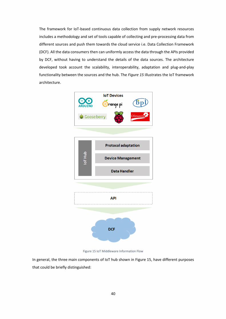
40
The framework for IoT-based continuous data collection from supply network resources
includes a methodology and set of tools capable of collecting and pre-processing data from
different sources and push them towards the cloud service i.e. Data Collection Framework
(DCF). All the data consumers then can uniformly access the data through the APIs provided
by DCF, without having to understand the details of the data sources. The architecture
developed took account the scalability, interoperability, adaptation and plug-and-play
functionality between the sources and the hub. The Figure 15 illustrates the IoT framework
architecture.
Figure 15 IoT Middleware Information Flow
In general, the three main components of IoT hub shown in Figure 15, have different purposes
that could be briefly distinguished:

41
Protocol Adaptation - This component is responsible for providing seamless communication
between IoT devices located at shop floor and other components of IoT hub. The main
functionality to be provided by this component is to allow connectivity for various devices with
different communication standards and request/response paradigm for devices integration into
the IoT hub. Major functionalities provided by the communication component are:
Provide an interface for communication with the IoT devices;
Creation and management of necessary communication channels (together with device
management component) and provide message routing when necessary;
Provide implementation for communication protocol conversion between the external
protocols and the internal communication protocol.
Device Management – This component contains core management functionality of the IoT hub
and handles creation of necessary communication channels between devices and IoT hub and
IoT hub and DCF. This component includes the functional sub-components to handle the
registration/connection of devices and their identification. The respective details of the device
like native communication protocol, device type, data type etc. are collected from the meta-
data of the device from the details stored in the DCF. At the same time, other important
objective of this component is to deal with the connectivity status of the devices. On the whole
this component keeps all the information about the different IoT devices registered and
connected to this IoT hub, providing information about the identifier of the device,
properties/capabilities of the device, registration and connectivity status of the device, working
status of the device and, authentication and authorization policies for device.
Data Handler - The IoT hub is the entry point of data from IoT resources. That means that this
module will then consume a huge amount of data coming from external sources. It is mandatory
to provide a module where data could be filtered, aggregated or merged allowing applications
to consume only specific/value-added data or pre-processed ones. Data handling module will be
responsible for providing such functionality. Data Handler Factory addresses the need for
filtering real time data being collected from the heterogeneous sources, thus providing pre-
processed data to DCF. Data handler pre-processes the data based on understanding the context
of the device and data processing constraints defined by the end users. Note that this
component will be designed in such a way that new implementations necessary for data
handling can be easily integrated into the Data Handler Factory. However, it is important to

42
emphasize that IoT hub intends to be a lightweight infrastructure with low processing capacity,
so the chosen technique to pre-processed data should be effective.
To summarize, IoT Hub collects data from the shop floor IoT resources, pre-processed and
provide it with the expected format to DCF. Outputs of IoT hub are data streams, which are
defined as “a sequence of digitally encoded signals used to represent information in
transmission.” - Federal Standard 1037C1. In the scope of IoT hub a data stream is a set of
timestamped relations, i.e. each element of the data stream consists of a set of tuples. The order
of the data stream derives from the ordering of the timestamps and the IoT hub provides
support to manage and manipulate these timestamps.
This way it is always possible to trace the temporal history of data stream elements collected
through IoT hub. It allows IoT hub to be the central observation tool for the physical world, in
which network and processing delays are inherent properties of the observation process, which
cannot be made transparent by abstraction. The data collected by IoT hub should be pre-
processed in order to filter out unnecessary and faulty data and this process can be achieved by
several techniques. Finally, this pre-processed data will be provided to the Data Collection
Framework through the DCF API for further processing.
3.2. Concept
In order to understand the general operation of the IoT hub, this section defines the high level
flow of configurations, data and commands during the device addition, as well as the registration
and run-time phases for collection of data from devices. Figure 16 presents the view of the
methodology to address the real time data collection from real world resources via IoT Hub, with
distinction between device registration and run time phases and control, data and
configurations flow. Data flow is represented by the flow of data from producers to consumers;
commands flow presents the actions that each of the components pass between each other at
different phases to invoke specific functional implementations while configurations flow is the
flow of configuration details for all the devices to be connected to the IoT hub.
The overall flow of Figure 16 is explained by the following steps. In order to add and register a
device in the IoT Hub, a conjunction of manual and automated interactions occur (1. and 2.)
1. The IT company personnel firstly create a new instance of the resource (IoT device) that
he wants to connect to platform. This step is performed at the DCF, where he provides
43
the details, including protocols, port, behaviour, data type etc. The instantiation of the
device also includes providing contextual details like the location of the device and data
handling constraints;
2. Following that registration activity, the DCF main component automatically provides the
IoT Hub the necessary information for device identification, behavioural properties and
data handling;
3. After registration, IoT Hub is ready for collecting data from the resource. Communication
component provides necessary implementation for communication between device and
IoT Hub. During run-time, devices are provided with communication channels based on
their communication protocols;
3.1. During the process of communication, the communication component works
together with the device management to identify the communication protocol of the
device, and creation of respective communication channels. At the same time this
step is also used for the runtime authentication and authorization of the device;
4. With successful creation of the communication channel and security check, the data is
forwarded towards a data handler for pre-processing of data (to filter faulty data);
4.1. Data handler component interacts with the device management to retrieve the
necessary rules and device properties to perform data filtering;
5. Pre-processed data is published to DCF message queue for further processing and
persistent storage;
6. Data consumers can then query DCF to request data collected from the real world
resources.

44
Figure 16 Methodology for addressing the real time data collection from real world resources
3.3. Application Scenario
The deployment of this middleware in an overall perspective is presented in Figure 17. It should
be clear that IoT Hubs are going to be deployed in the private infrastructure of the industries,
having direct connection to their IoT networks. This, means for the business scenario involving
number of industries, the industries will have independent IoT Hubs deployed on their private
premises. The integration between data collected by these independent hubs are performed by
the cloud services.
IoT Hub
Device Management
Data Handling
Communication
Data Source
Data Consumer IT Company Personel
Data Collection Framework
1
2 5
4.1
3.1
6
4
3

45
…
Figure 17 Middleware Model's Deployment
The fact that IoT Hub is configurable and extensible according to each company requirements,
allows to easily add and configure new devices from each pilots’ networks. These properties
provide the IoT Hub with the desired scalability to handle the constant growing and diversity of
company’s IoT devices.
For the implementation of the IoT Hub it is necessary to understand the IoT devices and the data
that needs to be collected from each Pilot. The next table summarizes the different contexts
that data collection can reach, as well as purpose in an industrial environment consideration in
Table 4.
IoT Hub IoT Hub IoT Hub IoT Hub
Cloud Services
(Data Collection Framework)
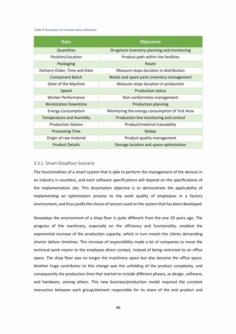
46
Table 4 Examples of context data collection
Data Objectives
Quantities Drugstore inventory planning and monitoring
Position/Location Product path within the facilities
Packaging Route
Delivery Order, Time and Date Measure stops duration in distribution
Component Batch Waste and spare parts inventory management
State of the Machine Measure stops duration in production
Speed Production status
Worker Performance Non conformities management
Workstation Downtime Production planning
Energy Consumption Monitoring the energy consumption of Test Area
Temperature and Humidity Production line monitoring and control
Production Station Product/material traceability
Processing Time Delays
Origin of raw material Product quality management
Product Details Storage location and space optimization
3.3.1. Smart-Shopfloor Scenario
The functionalities of a smart system that is able to perform the management of the devices in
an industry is countless, and each software specifications will depend on the specifications of
the implementation site. This dissertation objective is to demonstrate the applicability of
implementing an optimization process to the work quality of employees in a factory
environment, and thus justify the choice of sensors used on the system that has been developed.
Nowadays the environment of a shop floor is quite different from the one 20 years ago. The
progress of the machinery, especially on the efficiency and functionality, enabled the
exponential increase of the production capacity, which in turn meant the clients demanding
shorter deliver timelines. This increase of responsibility made a lot of companies to move the
technical work nearer to the employee direct contact, instead of being restricted to an office
space. The shop floor was no longer the machinery space but also become the office space.
Another huge contributor to this change was the unfolding of the product complexity, and
consequently the production lines that started to include different phases, as design, software,
and hardware, among others. This new business/production model required the constant
interaction between each group/element responsible for its share of the end product and

47
gathering all parties within a single space translated in an increase of the productivity through
enhanced communication among team members which in turn affected the output. As a result,
the control in the shop floor environment increased considerably through the detailed
management of activities and the flow of materials inside the plant, including employees,
materials, machines, and production time.
On another hand, to keep up with the technology efficiency it is necessary to ensure a
proportional efficiency in the workforce, offering them better work conditions. As the physical
boundaries are being bridged, a complex and competitive world focuses on innovation and
creativity is being developed. A smart shop floor now is one that ensures the optimal and
effective utilization of physical infrastructure and IT resources.
To build a smart shop floor is necessary to have an intelligent space that optimizes efficiency,
safety, comfort, system control and by collecting and analysing sensor data. In order to
interconnect different devices with different achievements, a smart shop floor will require
software with the ability to connect with everything – a middleware. It helps shop floor
managers to visualize information and make fast and precise decisions, through a management
system, increasing the employee’s productivity and decreasing the energy consumption and
operating costs.
For an illustrative example, let us consider three aspects that are directly related with the work
conditions in a shop floor, which are room temperature, luminosity and safety. For that purpose,
the sensors that can be chosen are:
Temperature: this sensor is useful to guarantee the general comfort, in maintaining the
temperature and air circulation, in case it is connected to electrical windows or A/C;
Photoresistor: this sensor will prevent the loss of visual capabilities caused by poor
illumination, it is also useful to turn on and off the lights, depending on the luminosity
levels;
Ultrasonic: considering that in a plant we have people and machines working side by
side, it is of utmost importance to guarantee the safety of all elements. Thus, this sensor
is responsible to measure the distances with the purpose of alerting the workers in case
they enter a restricted area for machinery only.
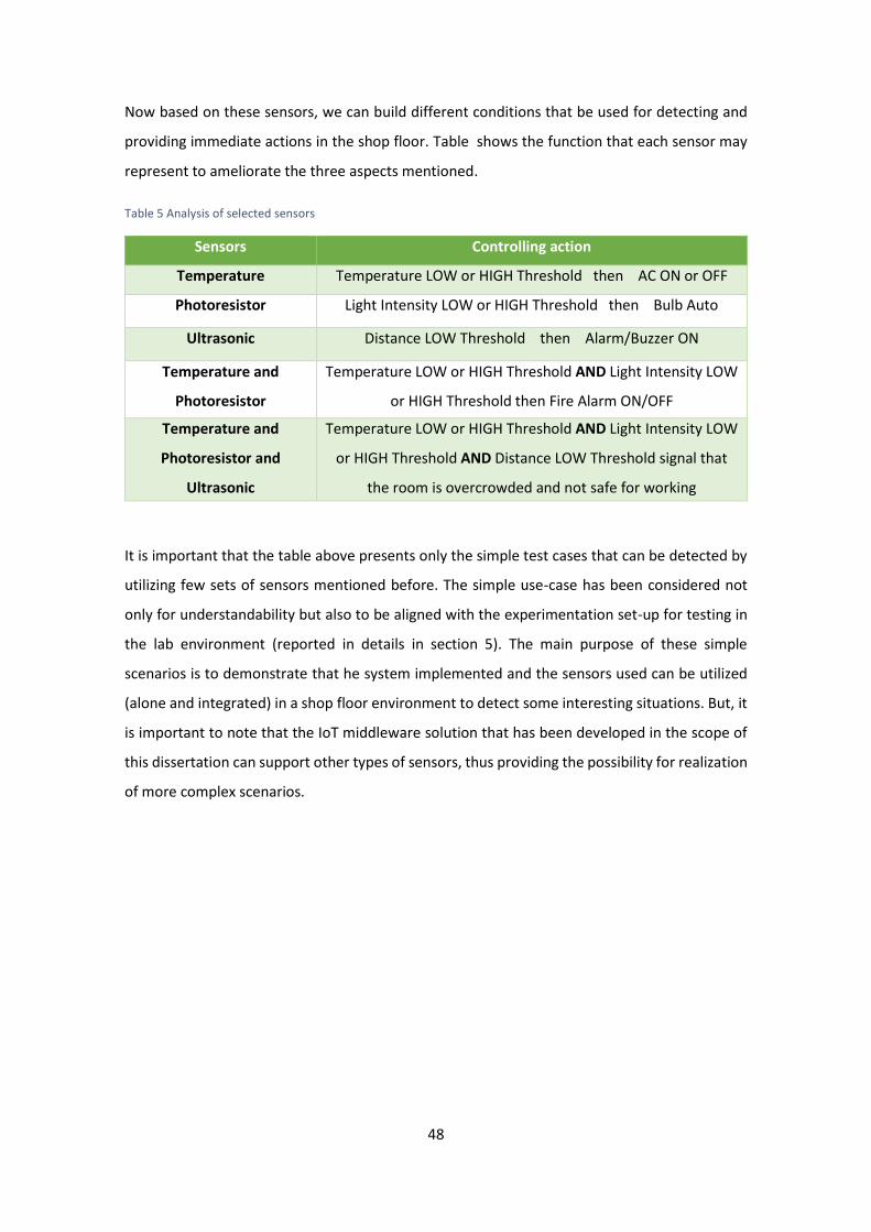
48
Now based on these sensors, we can build different conditions that be used for detecting and
providing immediate actions in the shop floor. Table shows the function that each sensor may
represent to ameliorate the three aspects mentioned.
Table 5 Analysis of selected sensors
Sensors Controlling action
Temperature Temperature LOW or HIGH Threshold then AC ON or OFF
Photoresistor Light Intensity LOW or HIGH Threshold then Bulb Auto
ON/OFF Ultrasonic Distance LOW Threshold then Alarm/Buzzer ON
Temperature and
Photoresistor
Temperature LOW or HIGH Threshold AND Light Intensity LOW
or HIGH Threshold then Fire Alarm ON/OFF
Temperature and
Photoresistor and
Ultrasonic
Temperature LOW or HIGH Threshold AND Light Intensity LOW
or HIGH Threshold AND Distance LOW Threshold signal that
the room is overcrowded and not safe for working
It is important that the table above presents only the simple test cases that can be detected by
utilizing few sets of sensors mentioned before. The simple use-case has been considered not
only for understandability but also to be aligned with the experimentation set-up for testing in
the lab environment (reported in details in section 5). The main purpose of these simple
scenarios is to demonstrate that he system implemented and the sensors used can be utilized
(alone and integrated) in a shop floor environment to detect some interesting situations. But, it
is important to note that the IoT middleware solution that has been developed in the scope of
this dissertation can support other types of sensors, thus providing the possibility for realization
of more complex scenarios.
49
4. Proof of Concept Implementation
In this chapter is presented the practical implementation of the middleware. The development
is based on the architecture explained in chapter 3. Before going into the details of the
implementation, the first section presents the requirements and functionalities of the system.
The following section presents the technology that has been used for the implementation the
proof of concept, explaining their purpose and choice. Subsequently, the characteristics of the
hub are explained in different modules.
4.1. Requirements and Functionalities
In this section, firstly we present the generic requirements that the IoT system should fulfil,
which have guided the overall architecture development and implementation of the middleware
solution discussed in this dissertation. It also presents the functionalities that have been
implemented along with some assumptions that have been made to realize the solution. This is
an important section for understanding the overall IoT system requirements and corresponding
functionalities that have been addressed in the proof-of-concept implementation.
Requirements
The architecture of the system should be interoperable: The main idea of having a
middleware is, mainly, to facilitate the data acquisition from a huge diversity of devices
which can have a large heterogeneity in communication domain.
The architecture of the system should be scalable: The system should be able to easily
expand as more devices are added and also facilitate the addition of other processing
techniques and security development levels. Another important advantage to increase
the scalability is its capacity to work in different platform systems.
The middleware should be able to react to a failure: In a real world there will be always
situations more difficult or impossible to control once we not leave in a perfect
environment. So the main idea of this requirement is “obligate” the middleware to be
more robust to external flaws.

50
The middleware should be able to pre-process data before sending it to DCF: One of
the main requirements of this lightweight middleware is doing a pre data filtering
according with specifications of each device.
The middleware should be able to identify the data belonging to each device: Despite
of having lots of sensors coupled at the same smart device, the idea is to maintain the
independence of each one.
The middleware should be capable to identify which devices are reliable: The data
collection is not made to acquire data of all kind of sensors. The architecture must be
done to choose which devices we want to insert in the hub.
The system should be capable to store data until DCF’s request: The fundamental idea
of collecting data is using it for a determinate purpose. Since the final user are the
clients, these hold the decision of when the data information provided by the sensors is
important. So, the middleware must be capable to acquire sensor data all the time, but
only send it when is requested by the Cloud application.
The system should guarantee data security: This is one of the main issues in our digital
world and not only in IoT systems. The idea is to provide data confidentiality, integrity
and availability. Since the main idea of this dissertation is to study and develop
mechanisms of pre-processed data in different communication protocols, the security
was not the main focus. However, this is a complex and very important requirement in
every IoT system.
Functionalities
Data collection is done only by known devices: The middleware receives a message
that contains the device’s characteristics that is going to be registered and only after
that is created the channel communication that allows the acquisition of data.
The middleware is capable to collect data from devices with different communication
protocols: The middleware was developed with the ability of collecting data by sensors
connected with three different communication protocols.
The middleware is prepared to easily add more communication protocols and more
pre-processed techniques: Each communication protocol is a Java Class, so if we want

51
to add more protocols (e.g. Bluetooth or RFID) we have to add the respective
dependencies and create another Java Class. The pre-processed techniques follow the
same strategy, however, this part will be dependent of the DCF’s message once the
characteristics of filtering of each device are sending by the Cloud.
The middleware has a bidirectional communication with the Cloud and unidirectional
communication with devices2: The bidirectional communication is for middleware
receive device’s information from the Cloud and then send the data collected. The
unidirectional communication is in the direction of data flow, devices to middleware.
The middleware stores each device’s data independently from each other: Each device
has its own stack where data is stored, in memory, before it is sent to the DCF.
The middleware store device’s information after switched off: After received by DCF,
this information is saved in a file.
The middleware guarantees a Plug&Play functionality: Since the moment that is
plugged in, the device launch automatically the software.
4.2. Technology Adopted
In this section it will be described and explained the technology used in this dissertation. Since
the development of this system is separate into a middleware and a sensor node, this section
divides the technology in two different parts: software and hardware. So, this section sets out
the technology used in the implementation of the hub and sensor nodes.
4.2.1. Software Technology
Middleware Software
The programme language used to develop this platform was Java. The main reasons for this
choice were its ease of writing, compiling, debugging and learning. It presents very useful
features such as the fact that is object-oriented, this allows the creation of modular programs
2 Since the proof of concept uses only sensors as devices, the communication with the middleware is
unidirectional. However, if the system is formed by sensors and actuators (that need to receive input
commands) it is perfectly feasible to have a bidirectional communication.
52
and reusable code. Also the capability of multithreading is an important advantage, allowing the
program to perform several tasks simultaneously within a program.
Moreover, the ability to run the same program on many different systems is crucial to World
Wide Web software, and Java succeeds at this by being platform-independent at both the source
and binary levels. This important aspect allowed to run the code on the computer (in NetBeans
IDE installed in Windows environment), allowing correct the errors in a more effective way and
testing it before inserting the program in the device (in Linux environment). In fact, this induces
further advantage of this programming language, its reliability, once Java puts a lot of emphasis
on early checking for possible errors, as Java compilers are able to detect many problems that
would first show up during execution time in other languages. Another important aspect for this
choice of language was security. Although it is not considered a main focus in this dissertation,
Java considers security as part of its design. The Java language, compiler, interpreter, and
runtime environment were each developed with security in mind.
In the code transfer was used FileZilla3 program, which greatly facilitates the communication
and files transfer between computer and the device in which was built the hub. Widely used in
the access of the device from the command line was Putty software.
Dependencies Usability
The implementation of the project required the use of some Jars, library Jars and other specific
Artifacts4. The local repository used was Maven (could be three types: local, central or remote
repository) that keeps all the dependencies used. When a Maven build command is executed, it
starts looking for dependency libraries in the following sequence:
Step 1 - The first place to search is in local repository;
Step 2 - If not found locally, the search will be extended to the central repository. If not
found there are two options: a remote repository has been mentioned – Step 4 or not -
Step 3;
3 FileZilla Client is a cross-platform FTP, FTPS and SFTP client with lots of features and an intuitive
graphical user interface.
4 An artifact is something produced by the software development process, whether it be software
related documentation or an executable file – Jar.
53
Step 3 – If a remote repository has not been mentioned, Maven simply stops the
processing and throws error;
Step 4 – Search dependency in remote repository, when it is found it is downloaded to
local repository for future reference.
Sensor Nodes Software
The sensors used were coupled, each of them, to a microcontroller responsible for reading the
input (sensor) and turn on output for subsequent delivery. To this end, it was used the Arduino
Programming Language, based on wiring, and the open-source Arduino Software (IDE), based
on processing. The programming language used was C++.
The implementation of sensor nodes’ communication in Arduino IDE required the addition of
appropriate libraries for each protocol:
The Serial communication, as having no hardware layer connected to Arduino, not
required extra libraries.
In Wi-Fi communication, it was integrated a CC3000 shield to Arduino, whose use
required the addition of the respective files.
However, in ZigBee implementation, in addition to the required libraries, it was
necessary to connect the ZigBee Arduino’s shield – router – with the ZigBee module
connected to the Raspberry Pi - coordinator. For this, it was used the XCTU program,
from Digi International.
4.2.2. Hardware Technology
Arduino
Arduino is an open-source prototyping platform based on easy-to-use hardware and
software. Arduino boards are able to read inputs - light on a sensor or a finger on a button - and
turn it into an output - activating a motor or turning on an LED. All Arduino boards are completely
open-source, empowering users to build them independently and eventually adapt them to
their particular needs. The chosen board for this thesis was the most common: Arduino Uno R3.
There are many other microcontrollers available for physical computing. Parallax Basic Stamp,
Net media’s BX-24, Phidgets, MIT's Handy board, and many others offer similar functionality. All
54
of these tools take the messy details of microcontroller programming and wrap it up in an easy-
to-use package. Arduino also simplifies the process of working with microcontrollers, but it
offers some advantage over other systems, such as:
Inexpensive - Arduino boards are relatively inexpensive compared to other
microcontroller platforms.
Cross-platform - The Arduino Software (IDE) runs on Windows, Macintosh OSX, and
Linux operating systems. Most microcontroller systems are limited to Windows.
Simple - The Arduino Software (IDE) is easy-to-use for beginners, yet flexible enough for
advanced users to take advantage of as well.
Open source and extensible software - The Arduino software is published as open
source tools and the language can be expanded through C++ libraries.
Extensible hardware - The plans of the Arduino boards are published under a Creative
Commons license, so experienced circuit designers can make their own version of the
module, extending it and improving it.
Raspberry Pi
A Raspberry Pi is a small device with an affordable price and works quite similar to a computer.
It is open hardware (with the exception of the primary chip), which runs many of the main
components of the board – CPU, graphics, memory, the USB controller, etc. These devices were
developed with the goal to create a low-cost device that would improve programming skills and
hardware understanding. It is slower than a modern laptop or desktop but it can provide all the
expected abilities that implies, at a low-power consumption level. Additionally, Raspberry Pi has
the advantage to have a large number of people who might be able to help if you have any
question regarding a project that you are working on because of the large reach of the
community. This is the big difference between choosing this device to any other available on the
market such as Allwinner A10 or CuBox. The available board to work in this thesis was the
Raspberry Pi 2 Model B.
Sensors
The sensors used in the implemented system were:
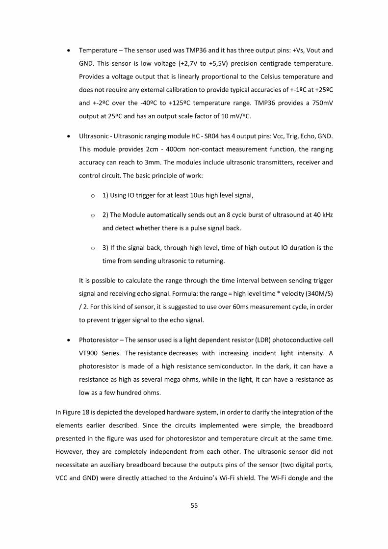
55
Temperature – The sensor used was TMP36 and it has three output pins: +Vs, Vout and
GND. This sensor is low voltage (+2,7V to +5,5V) precision centigrade temperature.
Provides a voltage output that is linearly proportional to the Celsius temperature and
does not require any external calibration to provide typical accuracies of +-1ºC at +25ºC
and +-2ºC over the -40ºC to +125ºC temperature range. TMP36 provides a 750mV
output at 25ºC and has an output scale factor of 10 mV/ºC.
Ultrasonic - Ultrasonic ranging module HC - SR04 has 4 output pins: Vcc, Trig, Echo, GND.
This module provides 2cm - 400cm non-contact measurement function, the ranging
accuracy can reach to 3mm. The modules include ultrasonic transmitters, receiver and
control circuit. The basic principle of work:
o 1) Using IO trigger for at least 10us high level signal,
o 2) The Module automatically sends out an 8 cycle burst of ultrasound at 40 kHz
and detect whether there is a pulse signal back.
o 3) If the signal back, through high level, time of high output IO duration is the
time from sending ultrasonic to returning.
It is possible to calculate the range through the time interval between sending trigger
signal and receiving echo signal. Formula: the range = high level time * velocity (340M/S)
/ 2. For this kind of sensor, it is suggested to use over 60ms measurement cycle, in order
to prevent trigger signal to the echo signal.
Photoresistor – The sensor used is a light dependent resistor (LDR) photoconductive cell
VT900 Series. The resistance decreases with increasing incident light intensity. A
photoresistor is made of a high resistance semiconductor. In the dark, it can have a
resistance as high as several mega ohms, while in the light, it can have a resistance as
low as a few hundred ohms.
In Figure 18 is depicted the developed hardware system, in order to clarify the integration of the
elements earlier described. Since the circuits implemented were simple, the breadboard
presented in the figure was used for photoresistor and temperature circuit at the same time.
However, they are completely independent from each other. The ultrasonic sensor did not
necessitate an auxiliary breadboard because the outputs pins of the sensor (two digital ports,
VCC and GND) were directly attached to the Arduino’s Wi-Fi shield. The Wi-Fi dongle and the

56
Zigbee coordinator were the physical devices attached to the Raspberry Pi (where middleware
runs) responsible to connect with the ZigBee and Wi-Fi shields. In order to facilitate the system
understanding, the serial cable responsible to connect the temperature sensor node to the
Raspberry Pi was not introduced in this figure.

57
Figure 18 Implementation of the physical system
Legend:
Data flow between sensor node and middleware
Hardware system entities
Hardware dongles communication – Wi-Fi and Zigbee Coordinator
Arduino with Wi-Fi shield and ultrasonic sensor Arduino with temperature sensor Arduino with ZigBee Shield (Rooter) and photoresistor ultrasonic sensor Raspberry Pi 2 - Middleware
58
4.3. IoT Hub Detailed
In this section we will present the details on IoT hub, which acts as the intermediate solution
between the shopfloor devices and cloud service. It is to be noted that even though the overall
solution is implemented as one java project, the idea is to describe each module separately
facilitates both the understanding and scalability for further enhancements. Lastly, it is
presented the synthesis of the global system’s modules along with the interactions between
modules in the hub as well as a sequence diagram of the system that represents a detailed view
of the interactions between the internal components (clearly marked in Figure 19).
4.3.1. Controller
This package is constituted by three Java classes responsible to manage devices’ data and post
it in the cloud:
DataPoster – Responsible for sending the information of th5e conglomerate of devices to the
cloud. Only one DataPoster object is created. This object is then shared by all the listeners. When
a measure is received by one device, the DataPoster is informed, that measure is added to data
structure with key/value (Device ID/Measure) and check if it is time to send that information. If
it is not, remains idle. Otherwise, retrieves all the information from that data structure, with the
help of Json’s message builds the message in a correct way, calls object Monitoring to monitor
the hub at that point in time and when it has all this information, then posts to a server it via
http post.
DeviceManagement – Core Implementation for managing the devices. The steps are:
1) Initialize the registered listeners (available data listener are added in the
Resources/configs.xml). This is done using DataListenerFactory, a class that follows the
factory pattern5;
2) Initialize the registered devices (received by DCF). Available devices are in
Resources/devices.txt. This is the trick to deal when the machine is off. The devices are
written in a file, since the implementation of a lightweight Hub does not allow (although
it is possible) storing any information in a local database;
3) Add each device to its own listener;
5 It can be explained in (Object Oriented Design 2016).
59
4) Monitor the overall life cycle of a device added on the hub.
FileChangedWatcher – Implementation of ChangeListener that will allow us to monitor the
Resources/devices.txt. The file devices.txt is used to store all the details of the devices that have
been added to the hub via DCF. When the file undergoes any modification, this class notifies
DeviceManagement to the initialization of new devices. The changes occur in this file whenever
the system admin adds/deletes/updates the device details via the interface provided in the DCF.
RESTservice – This class launch the REST service to receive the information from DCF - hub’s
configuration. Upon receiving a Json’s message from some link (for instance, localhost:
3000/DCFconf), it proceeds with an analysis of its content and verification that is indeed a
message that comes from DCF. If passes the validation builds a string with the extracted
information to be written in the configs/devices.txt with the FilerReader object.
4.3.2. Data Listeners
This package is constituted for the communication protocols supported by the hub. To authorize
the devices registration in the hub, each protocol checks the received ID in DCF’s message. This
ID is used to query data structure of the channel, using the contains method. If data structure
has the ID, the system proceeds as explained below. If not, the values received are eliminated.
Serial – This class initialize data listener serial port where the Arduino is attached. As in Linux is
impossible to listen the Arduino ports directly, it takes a symlink to another port of my choice
(e.g. /dev/tty63) and then is synchronized. It is made the connection with serial port and set the
serial port parameters (such as data rate, data bits, stop bits and parity none). Finally, the system
starts to listen if there are data transmission in that port. If not, it remains in loop until some
data appear in that port.
ZigBee - Instantiates a new object physically connected to the given port name (e.g. /dev/ttyS88)
and configured at the provided baud rate. From the device is necessary to know the serial port
name where XBee device (the coordinator) is attached to and the baud rate to communicate
with the sensor node. Other connection parameters will be set as default (8 data bits, 1 stop bit,
no parity, and no flow control). This class has an XBee message containing the remote XBee
device the message belongs to, the content (data) of the message and a flag indicating if the
message is a broadcast message (was received or is being sent via broadcast).
60
Wi-Fi - This class implements server sockets (by TCP protocol). A socket is an endpoint for
communication between two machines. A server socket waits for requests to come in over the
network (sensor node made a request to send data acquired). Then it is performed the
operations of filtering based on that request.
4.3.3. Models
This package is used for creating the model of the devices that are connected to the hub. This
class models of the overall IoT system by providing different types of properties (properties can
be complex ones such as device, monitoring etc. which themselves have properties defined
within themselves) such as:
DataField – This class implements concept hierarchy generation filter based on the information
in Resources/devices.txt;
DataRangeTypeLoHi – This class implements the data range filter based on the information in
Resources/devices.txt;
Device – This class keeps information about device such as id, name, protocol, datatype, range
and stack of measures. It is this class that prepares the string with the information required to
send to the DCF. The string messages from this object was overwritten in order to be structured
in a way that is ready to send to the DCF.
Measure – This class keeps value and timestamp of data collected. It belongs to Device’s class;
Monitoring – This class keeps track of hub status such as free disk, disk size, total ram, free ram
and CPU temperature. Linux keeps all your information on file and it was intended to make a
call to the operating system about the desired commands. More information can be acquired, if
necessary, in another application. This information is sent to a server for further analysis of hub’s
health.
4.3.4. Utilities
All Java classes responsible for reading files and preparing messages for sending or reading
information were implemented in this package, such as:
FilerReader – This class is responsible to read the information of Json’s message and store
devices’ information in a file Resources/devices.txt. It is called in DeviceManagement to initiate
the devices;
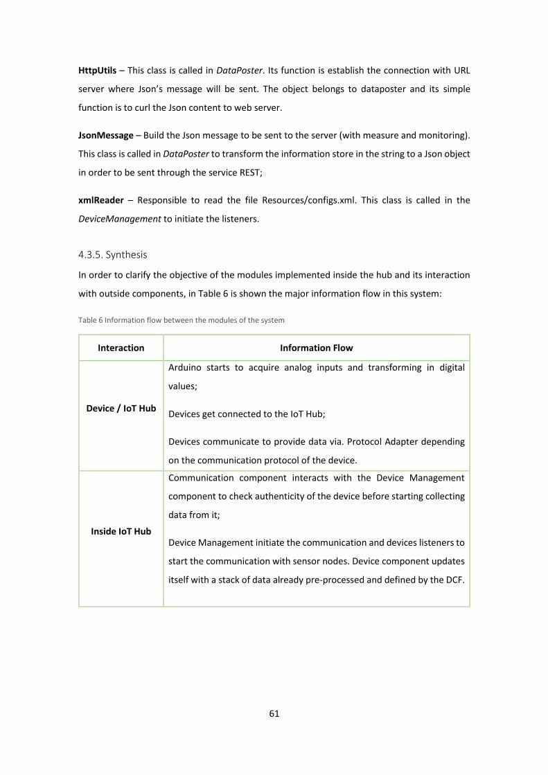
61
HttpUtils – This class is called in DataPoster. Its function is establish the connection with URL
server where Json’s message will be sent. The object belongs to dataposter and its simple
function is to curl the Json content to web server.
JsonMessage – Build the Json message to be sent to the server (with measure and monitoring).
This class is called in DataPoster to transform the information store in the string to a Json object
in order to be sent through the service REST;
xmlReader – Responsible to read the file Resources/configs.xml. This class is called in the
DeviceManagement to initiate the listeners.
4.3.5. Synthesis
In order to clarify the objective of the modules implemented inside the hub and its interaction
with outside components, in Table 6 is shown the major information flow in this system:
Table 6 Information flow between the modules of the system
Interaction Information Flow
Device / IoT Hub
Arduino starts to acquire analog inputs and transforming in digital
values;
Devices get connected to the IoT Hub;
Devices communicate to provide data via. Protocol Adapter depending
on the communication protocol of the device.
Inside IoT Hub
Communication component interacts with the Device Management
component to check authenticity of the device before starting collecting
data from it;
Device Management initiate the communication and devices listeners to
start the communication with sensor nodes. Device component updates
itself with a stack of data already pre-processed and defined by the DCF.

62
IoT Hub / DCF
DCF Resource Management communicates with the IoT hub to provide
the details of the resource instance being created;
IoT Hub communicates with the DCF Request/Response Message Queue
(API) to push data being collected into the DCF and to monitoring hub’s
health;
DCF communicates with IoT hub to update the devices registered in the
hub.
Specifically described and explained the internal operations of the hub implementation in the
earlier sub-sections, is shown in Figure 19, the sequence diagram representing the functionality
of the whole system encompassed around the developed middleware. This solution has
emerged based on the concept outlined in section 3.2 and also through the objectives that this
thesis intended to achieve. So, the mainly steps done by the system are:
1. Launch the DeviceManagement class;
2. Initialize the listeners. The xmlReader is called to read the settings in
Resources/configs.xml;
3. The listeners are launched using DataListenerFactory way. Every time that xmlReader
“send” a listener, DeviceManagement launch the DataListenerFactory to obtain the
channel communication. After that, the channel is initialized according with your
protocol adapter;
4. Initialize the devices. The FilerReader is called to read the settings in
Resources/devices.txt;
5. Each device is added to your own listener (according with communication protocol);
6. Launch RESTservice;
7. Execute the function MonitorForNewDevices that contains a FileChangedWatcher
object that is constantly monitoring the changes in devices.txt file, in order to initialize
new devices added (by DCF through RESTservice) in this file;
8. After the communication process is being done, the system starts to collecting data
coming from data sources;
9. The concept hierarchy generation and range filter are executed (by DataField and
DataRangeTypeLoHi, respectively);
10. After data filtering, is created an object Measure (with device’s ID and the value
collected) that will be added to the stack of this Device’s class;

63
11. The string containing device’s information is sent to DataPoster;
12. In DataPoster, if the time defined by DCF to send the message is reached, the string that
contains device’s information is conglomerate with the string responsible to Monitoring
(this class is executed at this point) the hub’s health.
13. The JsonMessage class is called in DataPoster;
14. Posteriorly, is sent the Json’s message (measure and monitoring) through a class called
in DataPoster – HttpUtils.
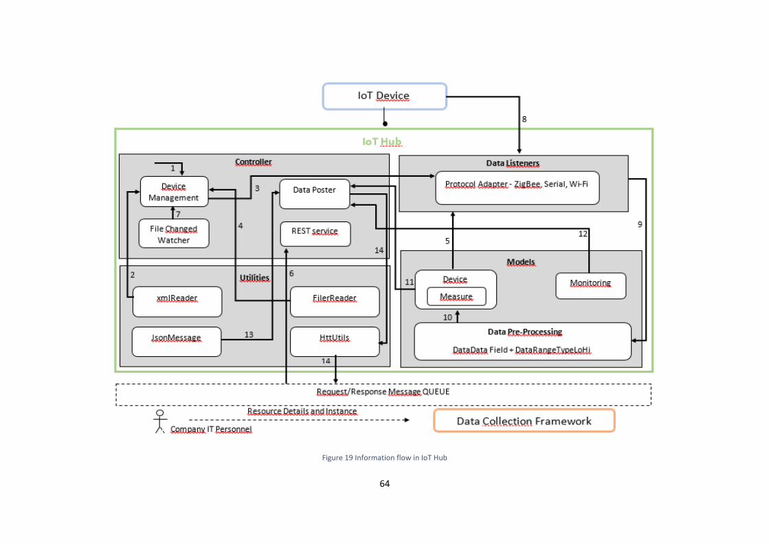
64
Figure 19 Information flow in IoT Hub

65
5. Testing and Hypothesis Validation
In this section the testing of implementation will be addressed by validating the requirements
and functionalities of the system. The testing aims to evaluate the level of confidence of using
the system in normal circumstances. However, since testing of realistic systems can never be
exhaustive because it is limited to a restricted period of time, it is not possible to ensure
complete accuracy of a system implementation. Testing can only show the presence of errors,
not their absence (Tretmans 2001).
To sum up, in this chapter will be presented:
The methodology applied to the proof-of-concept implementation;
The main tests performed based on the chosen methodology;
The validation of hypothesis and the implemented concept.
5.1. Testing Methodology
The importance of testing is explicit explained in Volume 2 of (Marciniak 2002). In this book is
concluded that, as maintenance and upgrades of existing systems increase in number and depth,
a significant amount of testing will also be needed to verify the systems after the changes are
made.
In this perspective, there are number of methods that can be applied to guarantee the quality
of a deployed system. Testing is involved in every stage of software life cycle, but the testing
done at each level of software development is different in nature and has different objectives.
Mainly there are four key steps (Luo 2001):
Unit Testing: is done at the lowest level. It tests the basic unit of software, which is the
smallest testable piece of software;
Integration Testing: is performed when two or more tested units are combined into a
larger structure;
66
System Testing: tends to affirm the end-to-end quality of the entire system, evaluating
its functionality;
Acceptance Testing: is done when the completed system is handed over from the
developers to the customers or users. The purpose of acceptance testing is rather to
give confidence that the system is working than to find errors.
Based on the information flow, a testing technique specifies the strategy that is used to select
input test cases and analyse its results, as different techniques reveal different quality aspects
of a software system. There are two major categories of testing techniques, functional and
structural:
Functional Testing: the software program or system under test is viewed as a “black
box”. Is evaluated by observing the box externally with no reference of its internal
details or implementation. The selection of test cases for functional testing is based on
the requirement or design specification of the software entity under test. Functional
testing emphasizes on the external behaviour of the software entity;
Structural Testing: the software entity is viewed as a “white box”. The selection of test
cases is based on the implementation of the software entity. The goal of selecting such
test cases is to analyse each code line executed, at least one time, covering all possible
paths of execution, specific statements and branches. Structural testing emphasizes on
the internal structure of a computer program.
5.1.1. Testing and Test Control Notation
Testing research techniques leads to obtaining practical testing methods and tools. Progress
towards this achievement requires fundamental research, and the creation, refinement,
extension, and popularization of better methods. For this reason, the chosen methodology was
Testing and Test Control Notation (TTCN).
The Testing and Test Control Notation, previously called Tree and Tabular Combined Notation,
which is defined in (ETSI 2013), is a notation standardised by the ISO/IEC 9646-1 for the
specification of tests for communicating systems and has been developed within the framework
of standardised conformance testing.

67
Based on the “black box” testing model, the tests are defined through tables containing general
description, constraints, behaviour and verdict. In TTCN, the behaviour test is defined by a
sequence of events which represent the test per se. The sequence of events can be represented
by a tree with branches of actions based on the evaluation of the system output after one (or a
series of) executed event(s). Each event has its own respective level of indentation and can be
of one of two types, action or question:
Actions are preceded by an exclamation point before its brief description, and represent
actions performed on the SUT;
Questions are preceded by an interrogation point, and represent evaluations of the
output of the SUT after one or more actions are completed. Since the answer can be
positive or negative, multiple questions can exist at the same indentation level, covering
all possible outputs of the system.
After a completion of a TTCN test table a verdict must be deliberate: “Success”, “Failure” or
“Inconclusive”. This verdict is based on the sequence of events which travel through the tree,
and was conditioned by the outputs of the system and evaluated by the question events. Table
7 is a simplified example of a TTCN table test.
Table 7 Example of a TTCN test in table format (Tretmans 2001)
Test Case Dynamic Behaviour
Test Case: Conn_Estab
Purpose: Transport / Connection
Purpose: Check connection establishment with remote initiative
Behaviour Constraints Verdict
+preamble
LT ! T-PDU-connect-request
UT ? T-SP-connection-indication
UT ! T-SP-connection-response
LT ? T-PDU-connect-confirm Success
OTHERWISE Failure
LT ? T-PDU-disconnect-request Inconclusive
OTHERWISE Failure
68
5.2 Testing Implementation
As explained in 5.1, there are two main techniques for testing: functional and structural.
Although both techniques were used, the structural test was performed during the code
development (using the tools provided by the IDE NetBeans). Thus, this section lists the
functional tests (intended to demonstrate the capabilities of middleware) resulting from a
subsequent acceptance of structural tests. In testing process of the architecture implemented
in this work, it was taken into consideration more specific criteria such as:
Interoperability – between devices and the hub, as it is a key element in its
development;
Recovery capacity – what is the hub’s behaviour when the communication wires are
physically disconnected, power is turned off or the devices and communication channels
are turned down;
Performance - to determine how fast a feature of a system performs under a particular
workload, in order to validate that the system meets the expected response time.
To address the functional and non-functional testing of the implementation, all the models that
were explained in the section 4.3, will be demonstrated and followed by showing how the
middleware works. Figure 20 presents the main perspective of the tested system divided by five
layers (respectively from down to up: acquisition, transport, collection, transport and delivery)
where the data has to pass from the edge – sensor nodes, to the core – cloud platform.

69
DCF
Message Protocol REST/HTTP
Middleware
Communications
Protocols
Sensor Nodes
Figure 20 Technologies used for testing
5.3.1. Functional Tests
In the test definition, it is intended to describe the general purpose of the test implemented.
Later, in test execution, it is intended to demonstrate the different tests that have occurred and
that demonstrate the system reliability.
Test Definition
Since the goal is to test whether the data collection is carried out in a correct way, the only test
that serves associated with the ultimate goal is the functionality of the entire system, defined in
Table 8. The system fails if it is not established communication or data filtering is not being done
or not send data in the time set by DCF.
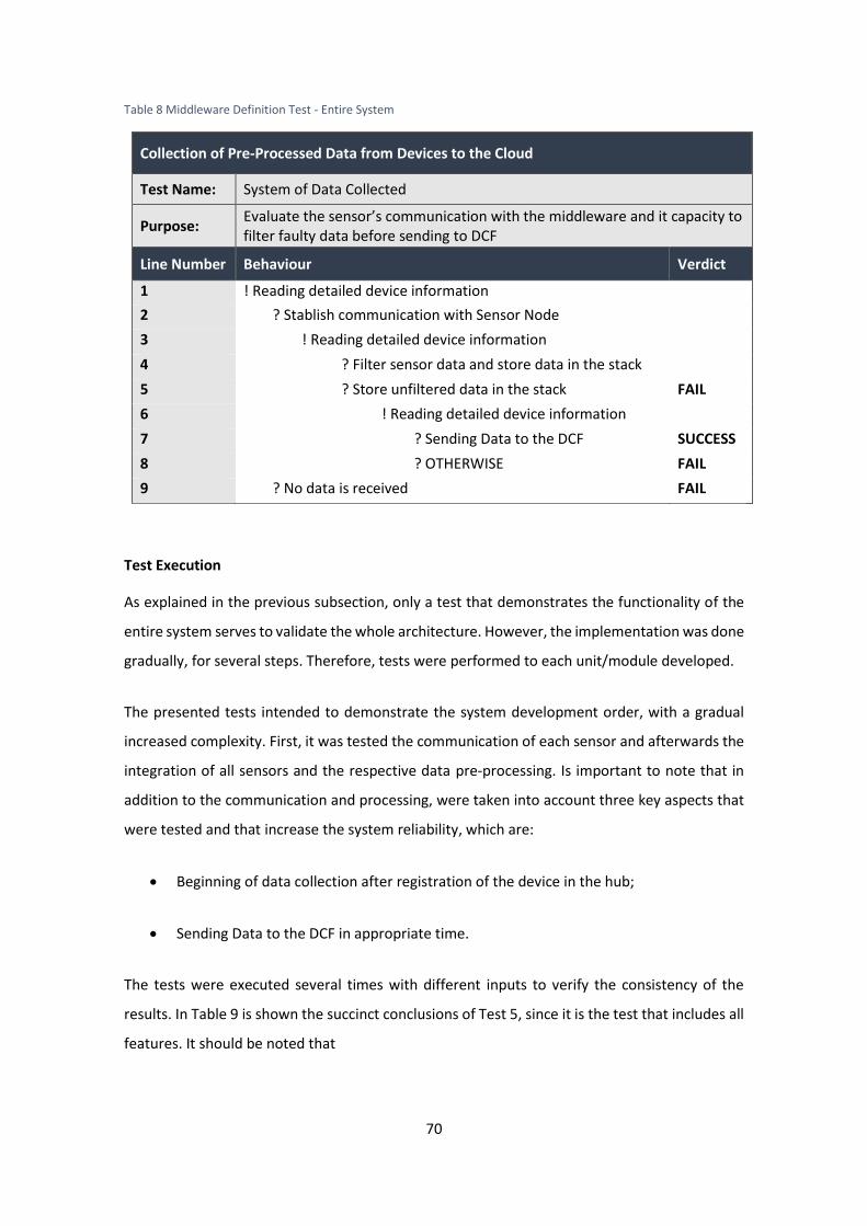
70
Table 8 Middleware Definition Test - Entire System
Collection of Pre-Processed Data from Devices to the Cloud
Test Name: System of Data Collected
Purpose: Evaluate the sensor’s communication with the middleware and it capacity to filter faulty data before sending to DCF
Line Number Behaviour Verdict
1 ! Reading detailed device information
2 ? Stablish communication with Sensor Node
3 ! Reading detailed device information
4 ? Filter sensor data and store data in the stack
5 ? Store unfiltered data in the stack FAIL
6 ! Reading detailed device information
7 ? Sending Data to the DCF SUCCESS
8 ? OTHERWISE FAIL
9 ? No data is received FAIL
Test Execution
As explained in the previous subsection, only a test that demonstrates the functionality of the
entire system serves to validate the whole architecture. However, the implementation was done
gradually, for several steps. Therefore, tests were performed to each unit/module developed.
The presented tests intended to demonstrate the system development order, with a gradual
increased complexity. First, it was tested the communication of each sensor and afterwards the
integration of all sensors and the respective data pre-processing. Is important to note that in
addition to the communication and processing, were taken into account three key aspects that
were tested and that increase the system reliability, which are:
Beginning of data collection after registration of the device in the hub;
Sending Data to the DCF in appropriate time.
The tests were executed several times with different inputs to verify the consistency of the
results. In Table 9 is shown the succinct conclusions of Test 5, since it is the test that includes all
features. It should be noted that

71
Test 1: The simplest case to be tested occurred with the Serial. Since the communication
is done via cable, the data transmission is safer than other types of wireless
communication. So, it is easier to test if the problem is the implementation of the hub
and not the configuration between communication modules once they do not exist. To
test if data collected was real, the temperature sensor was heated by hand for a few
seconds to check that the values increased and then turned to decline to relatively
constant value that remained before being heated.
Test 2: The second protocol to be tested was ZigBee. To avoid connection problems
between the communication modules relating to its operating range, the router was
tested at a maximum distance of 5 meters from the coordinator. Considering that the
router (the shield that communicate with Raspberry Pi coordinator) did not use the only
Arduino serial port, it was possible to verify the sensor data by the output window of
the Arduino IDE. Afterward, these values were compared with the values read by the
middleware. As in the first test, it was also verified the reliability of the sensor. During
data collection, the sensor was covered and uncovered, to see if the values were
changing in case of the sensor has more or less light shining on it.
Test 3: The last protocol to be tested was Wi-Fi. In the test laboratory, the only network
available was the Eduroam (European network for the academic community) that
contains security services that made it impossible to connect the devices. The
alternative was to connect both devices to a network created by a smartphone – a
portable hotspot. As in the second test, to avoid range problems, the Wi-Fi Arduino’s
shield and the dongle connected in Raspberry Pi were placed to a maximum of 5 meters
from the hotspot to ensure that there were no range problems. The data collected by
the sensor was compared in the same manner as the second test. Finally, the reliability
of the ultrasonic sensor was also tested, towards and away of objects so that the sensor
could read different distances.
Test 4: After testing the communication of all units separately, it was executed the
integrity test. The main objective of this test was to verify if there was no problem with
the three threads running simultaneously. Since the goal was to have sensors
completely independent and different from the others, the data collection was
performed with different sending times.

72
Test 5: The last test to be executed was the system test. After the communication only
the data pre-processing strategies needed to be tested. In order to test data filtering,
was introduce in the system three devices with different purposes. It should be notice
that both filtering techniques was tested in all sensors. The test presented in Table
marks the first experimentation of the system test. The input 1 is protocol adaptation,
the method is connect both parts (input 2), the event is acquisition of data (input 3) and
lastly, the input 4 is the acquired data in the sensor node. The output 1 represents the
value received in the channel communication before the acquisition of data (always
none, obviously) and output 2 the data pre-processed, stored in memory, before being
sent to DCF. The devices’ characteristics were:
Serial
{"action":"add","id":225712,"name":"test10","dataType":"units","dataRange":{"lowerRang
e":0,"higherRange":100},"datafilterrule":{"dataFilterRule":"N/A"},"CommunicationListener
Type":"DataListenerSerialPort"}
ZigBee
{"action":"add","id":214713,"name":"test11","dataType":"units","dataRange":{"lowerRang
e"250:,"higherRange":600},"datafilterrule":{"dataFilterRule":"N/A"},"CommunicationListen
erType":"DataListenerXbee"}
Wi-Fi
{"action":"add","id":215785,"name":"test12","dataType":"units","dataRange":{"lowerRang
e":0,"higherRange":500},"datafilterrule":{"dataFilterRule":"N/A"},"CommunicationListener
Type":"DataListenerWifi"}
The dataType filter was tested in serial communication. In this case, the node is constituted
by the temperature sensor that provides values with decimals. Here we also tested the
concept of hierarchy generation. For instance, if sensor node reads 25,7 Celsius degrees, IoT
hub stores in memory 26 Celsius degrees.
In ZigBee communication was tested dataRange. The sensor measure values between 100
and 200 when a hand is put over the sensor instead of values near to 500. So, the lower
range of this device was 250. Which was tested to see if this values is eliminated for being
too low. The same procedure was performed for higher values.
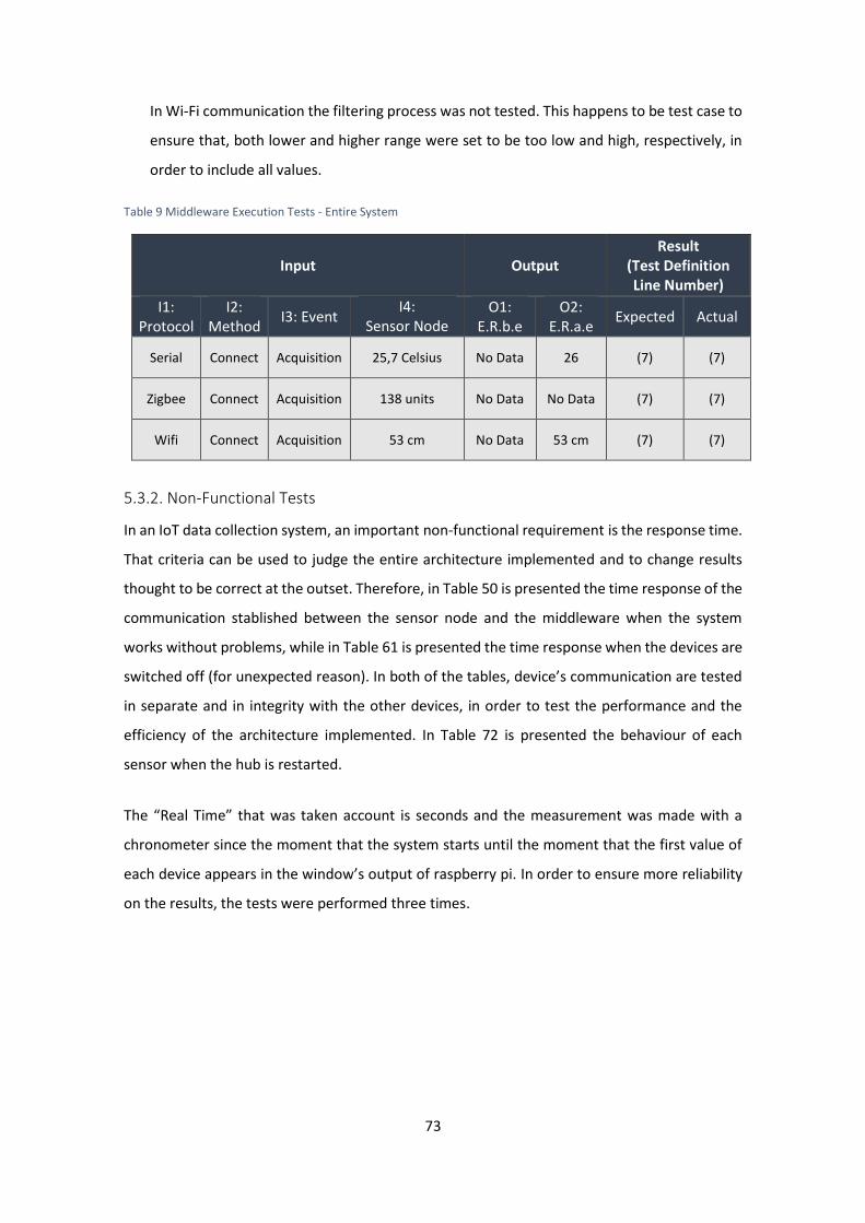
73
In Wi-Fi communication the filtering process was not tested. This happens to be test case to
ensure that, both lower and higher range were set to be too low and high, respectively, in
order to include all values.
Table 9 Middleware Execution Tests - Entire System
Input Output Result
(Test Definition Line Number)
I1: Protocol
I2: Method
I3: Event I4:
Sensor Node
O1: E.R.b.e
O2: E.R.a.e
Expected Actual
Serial Connect Acquisition 25,7 Celsius No Data 26 (7) (7)
Zigbee Connect Acquisition 138 units No Data No Data (7) (7)
Wifi Connect Acquisition 53 cm No Data 53 cm (7) (7)
5.3.2. Non-Functional Tests
In an IoT data collection system, an important non-functional requirement is the response time.
That criteria can be used to judge the entire architecture implemented and to change results
thought to be correct at the outset. Therefore, in Table 50 is presented the time response of the
communication stablished between the sensor node and the middleware when the system
works without problems, while in Table 61 is presented the time response when the devices are
switched off (for unexpected reason). In both of the tables, device’s communication are tested
in separate and in integrity with the other devices, in order to test the performance and the
efficiency of the architecture implemented. In Table 72 is presented the behaviour of each
sensor when the hub is restarted.
The “Real Time” that was taken account is seconds and the measurement was made with a
chronometer since the moment that the system starts until the moment that the first value of
each device appears in the window’s output of raspberry pi. In order to ensure more reliability
on the results, the tests were performed three times.

74
Table 50 Non-functional test in normal conditions
Communication Conditions
Test 1
(seconds)
Test 2
(seconds)
Test 3
(seconds)
Stablish Serial
communication
Single 3 2 2
Integrated 2 2 2
5S4tablish ZigBee
Communication
Single 4 5 4
Integrated 5 6 5
Stablish Wi-Fi
Communication
Single 51 48 50
Integrated 46 51 48
Table 61 Non-functional test in abnormal conditions
Communication
Conditions
Test 1
(seconds)
Test 2
(seconds)
Test 3
(seconds)
Serial device restarting Single 2 2 2
Integrated 3 4 2
ZigBee device restarting Single 3 3 4
Integrated 4 4 4
Wi-Fi device restarting Single 49 47 48
Integrated 48 49 48
Table 72 Sensors' behaviour in an abnormal situation in the hub
Protocol Test 1 (seconds) Test 2 (seconds) Test 3 (seconds)
Hub restarting Serial 3 3 3
ZigBee 5 5 3
Wi-Fi 47 52 47
5.3. Hypothesis Validation
From the executed tests, the main conclusion that can be drawn is that the implemented proof
of concept successfully passed all the tests. The main improvement that is necessary to be made
from the observed tests is that the delay that occurred in the Wi-Fi communication to start
collecting data needs to be solved. This delay comes mainly due to the handshaking (about 20
seconds to connect in the network) and the request message sent to the hub (about 25 seconds
to find the IP address of the hub). However, after connection, this protocol works perfectly equal
to the other protocols. In final analysis, it provides a system capable to transmit the data from
the sensors to the cloud. The tests done to the system were designed taking into consideration
75
the problem characteristics presented in section 4.1. However, some features and
functionalities can be added and improved as it is explained in future works (c.f. section 6.2).
In summary, it can be concluded that the hypothesis formulated in section 1.3 is a valid
hypothesis, and that the created architecture is capable of handling with the objectives defined.
Furthermore, since the industrial target of this implementation was the SME’s, the proposed
middleware solution was achieved successfully once it fulfilled the main objectives and it was
able to collect data from sources and send it to the cloud, detecting and filtering the unnecessary
data. The main achievements are the realization of IoT middleware solution that allows
extendibility across different protocols and increase the dependability of the data collected by
eliminating faulty data at the source. At the same time the solution presented decreases
communication and processing overload between the data producers and consumers.
Another important aspect of the developed solution is affordability both from the perspective
of installation cost and resource consumption. In fact, the technology used is quite affordable.
The sensors and microcontrollers used are easily to acquire as well as the device to develop the
hub. This last one, despite of being affordable, has a considerable processing capacity, being
capable of supporting communication with multiple sensors and respective acquisition and pre-
filtering data for onward delivery to the DCF.
5.4. Scientific and Industrial Validation
The research results of this dissertation mainly the implementation has been performed in close
collaboration with GRIS, UNINOVA. The Group of Research in Interoperability of Systems (GRIS)
is inserted in the centre of technology and systems Uninova research institute, which belongs to
the Faculty of Science and Technology of Universidade Nova de Lisboa (UNL), and is part of this
project. Its main contribution is the scientific development and technological solutions in the
field of interoperability of systems and applications, to be subsequently used in industry
(Uninova 2014). Besides the industrial use-cases from the FP8-FoF project C2NET, the
implementation is based the following publication of the fellow researchers at GRIS, UNINOVA:
Sudeep Ghimire; Raquel Melo; José Ferreira; Carlos Agostinho and Ricardo Gonçalves:
“Continuous Data Collection Framework for Manufacturing Industries”. OTM Workshops
2015: 29-40 (Ghimire et al. 2012)
76
AGOSTINHO, C. et al., 2016. A Distributed Middleware Solution for Continuous Data Collection in
Manufacturing Environments, IESA-2016 Workshop on Cloud Collaborative Manufacturing
Networks (AGOSTINHO et al. 2016)
On the industrial validation front, this research work has been performed in the scope of C2NET
- Cloud Collaborative Manufacturing Networks – which aims to increase productivity, reduce
complexity for the decentralization of production systems, as well as to increase the reaction of
businesses to changing tools and optimization that the market demands. This project is mainly
directed to SMEs, due to the fact that it has scarce access to self-management as it requires
more advanced efficiency tools and help increase competitiveness systems (C2NetProject 2015).
The research results from this thesis are being applied in the industrial use-cases being
developed in the C2NET scope which can be understood in details from (C2NET Consortium
2015). C2NET is an ongoing project thus, actual industrial validation results are not available
currently.

77
78
6. Conclusions and Future Work
6.1. Conclusions
In an IoT paradigm, distributed scenario prevails where the data sources are physically separated
and are often consumer by autonomous data consumers, which are often the higher level
applications with functionality for high-end data analytics and event detection. But, these type
of distributed scenario can create lots of problems for scalability and maintenance if the data
sources and data consumers are tightly coupled. It, means the changes in the standards of data
sources or consumers for communication and data exchange changes, the overall systems needs
to undergo respective changes to deal with the new requirements. So, it is an utmost industrial
and technological solution need to have a system for seamless integration of data sources with
high level of abstraction between the data sources and consumers. . Middleware aims to reduce
the complexity of such systems by hiding unnecessary details. As with most types of software,
there are many different types of middleware, each having different aims and their own set of
advantages and disadvantages. There are no good or bad types of middleware; the best choice
depends on both the task at hand and the skills of the team who will be using it.
This research work presents a technological solution along with necessary reference
architecture for scalable for IoT Middleware. The approach that has been presented will
enhance the use of IoT in the industrial world and seamless integration of existing legacy devices.
Besides the technological solution this research work also provides detailed study on the
challenges and issues in IoT paradigm that can pave path for further research and
implementations. The results from this dissertation also play an important part for realization
of complete C2NET data collection framework. In comparison to some existing solutions in IoT
paradigm, the main advantage of this solution is affordability because the test results by utilizing
low-powered computing resources such as raspberry-pi has produced results as expected. Thus,
the technical results from this research work can be an affordable solution for SMEs who want
to deploy IoT based solutions.
6.2. Future Work
One of the possible enhancements that could be applied to the architecture developed is the
integration of security constraints such as data authentication, access control and client privacy.

79
The issues that can be associated in an unsecure system are enormous and to deploy this
software in an industrial vision is crucial to put data security on a par with the quality of a
product. Since there are several aspects to consider and data security must be made at a later
stage to the implementation of the product, this aspect was taken into account in some
parameters but was has not been developed in the current implementation. Building security
and trust over IoT ecosystem can be an interesting and challenging future work.
The next future work that needs to be undertaken is extending the solution and testing with
other different types of devices and their respective standards. Even, though the solution
supports easy integration of protocol adapters, it requires the implementation of protocol
adapter module to handle more protocols such as Bluetooth, RFID or NFC. At the same time
some further enhancements are necessary in the data filtering component to enable
specification of more complex data filtering for instance by utilizing the rules that can be applied
over a long stream of data rather than a single data stream. Other direction that be taken for
the data filtering process is making use of statistical analysis to re-construct missing data in the
collected stream. Note that statistical analysis consumes quite a lot of resources, so doesn’t fit
in the requirement of light-weight IoT middleware, but can be a very interesting solution for
cases with higher computing resources.
Another future work is towards the compatibility of the solution across various platforms.
Currently the solution is compliant with Debian OS and all the tests were performed in the scope
of Debian OS. It will also be an interesting challenge to further reduce the resource consumption
by the solution and test them on other low-resources computing devices.

80
References
Aazam, M. & Huh, E.N., 2014. Fog computing and smart gateway based communication for cloud of things. Proceedings - 2014 International Conference on Future Internet of Things and Cloud, FiCloud 2014, pp.464–470.
Aazam, M. & Huh, E.N., 2015. Fog computing micro datacenter based dynamic resource estimation and pricing model for IoT. Proceedings - International Conference on Advanced Information Networking and Applications, AINA, 2015-April, pp.687–694.
Aberer, K., Hauswirth, M. & Salehi, A., 2006. Middleware support for the “Internet of Things.” 5th GI/ITG KuVS Fachgespräch “Drahtlose Sensornetze”, (5005), p.5.
Abowd, G.D. et al., 1999. Towards a Better Understanding of Context and Context-Awareness. , pp.304–307.
AGOSTINHO, C. et al., 2016. A Distributed Middleware Solution for Continuous Data Collection in Manufacturing Environments,
Amaravadhi, S., 2015. FOG COMPUTING. Available at: http://www.slideshare.net/saisharansai/fog-computing-46604121 [Accessed August 11, 2016].
Atzori, L., Iera, A. & Morabito, G., 2010. The Internet of Things: A survey. Computer Networks, 54(15), pp.2787–2805. Available at: http://linkinghub.elsevier.com/retrieve/pii/S1389128610001568.
Bechtold, J. et al., 2014. Industry 4.0 - The Capgemini Consulting View. Capgemnini Consulting, p.31.
Bonomi, F. et al., 2012. Fog Computing and Its Role in the Internet of Things. Proceedings of the first edition of the MCC workshop on Mobile cloud computing, pp.13–16. Available at: http://doi.acm.org/10.1145/2342509.2342513\npapers2://publication/doi/10.1145/2342509.2342513.
Bradley, J., Barbier, J. & Handler, D., 2013. Embracing the Internet of Everything To Capture Your Share of $ 14 . 4 Trillion. Cisco, pp.1–18.
Brown, E., 2014. The Cloud - Gateway to Enterprise Mobility. Available at: http://ericbrown.com/cloud-gateway-enterprise-mobility.htm [Accessed August 11, 2016].
Buest, R., 2013. Analyst POV › Fog Computing: Data, Information, Application and Services needs to be delivered more efficient to the enduser. Available at: http://analystpov.com/analysis/fog-computing-data-information-application-and-services-needs-to-be-delivered-more-efficient-to-the-enduser-22362 [Accessed June 3, 2016].
Buyya, R., Broberg, J. & Goscinski, A., 2011. Cloud Computing Principles and Paradigms,
C2NET Consortium, 2015. Industrial scenarios addressed by C2NET Platform. , pp.1–84.
C2NetProject, 2015. C2Net | Overview. Available at: http://c2net-project.eu/overview [Accessed February 17, 2016].
Camarinha-matos, L.M. & Terminology, B., 2016. SCIENTIFIC RESEARCH Unit 2 : SCIENTIFIC METHOD. , pp.2009–2016.
Chaqfeh, M.A. & Mohamed, N., 2012. Challenges in middleware solutions for the internet of things. Proceedings of the 2012 International Conference on Collaboration Technologies and Systems, CTS 2012, pp.21–26.
Chen, H. et al., 2004. Meet the Semantic Web in Smart Spaces. IEEE Internet Computing, 8(6), pp.69–79. Available at:

81
http://ieeexplore.ieee.org/xpls/abs_all.jsp?arnumber=1355924&tag=1\nhttp://www.computer.org/csdl/mags/ic/2004/06/w6069-abs.html.
Colitti, W. et al., 2011. Evaluation of Constrained Application Protocol for Wireless Sensor Networks. Local & Metropolitan Area Networks (LANMAN), 2011 18th IEEE Workshop on.
Collett, T.H.J., MacDonald, B. a & Gerkey, B.P., 2005. Player 2.0: Toward a Practical Robot Programming Framework. In Proceedings of the Australasian Conference on Robotics and Automation, p.8.
Davies, R., 2015. Industry4.0 - Digitalisation for productivity and growth. European Union, (September).
Doulkeridis, C. et al., 2007. Peer-to-peer similarity search in metric spaces. Proceedings of the 33rd international conference on Very Large Databases, pp.986–997. Available at: http://portal.acm.org/citation.cfm?id=1325851.1325962.
Duffy, P., 2013. A Cisco View on IoT Protocols. Available at: http://blogs.cisco.com/digital/beyond-mqtt-a-cisco-view-on-iot-protocols [Accessed August 11, 2016].
Esposito, C., Russo, S. & Di Crescenzo, D., 2008. Performance Assessment of OMG compliant Data Distribution Middleware.pdf. In Parallel and Distributed Processing, 2008. IPDPS 2008. IEEE International Symposium on Miami. IEEE.
ETSI, 2013. Testing and Test Control Notation. Available at: http://www.ttcn-3.org/ [Accessed August 29, 2016].
Fernandes, J.L. et al., 2013. Performance evaluation of RESTful web services and AMQP protocol. International Conference on Ubiquitous and Future Networks, ICUFN, (July 2013), pp.810–815.
Fersi, G., 2015. Middleware for internet of things: A study. Proceedings - IEEE International Conference on Distributed Computing in Sensor Systems, DCOSS 2015, 2(3), pp.230–235.
Fielding, R.T. & Taylor, R.N., 2002. Principled Design of the Modern Web Architecture.
Fosstrak, 2009. Fosstrak - Open source RFID Software Platform. Available at: http://fosstrak.github.io/ [Accessed February 20, 2016].
Gartner, 2015. Gartner Says 6.4 Billion Connected “Things” Will Be in Use in 2016, Up 30 Percent From 2015. Available at: http://www.gartner.com/newsroom/id/3165317 [Accessed February 18, 2016].
Ghimire, S. et al., 2012. On the Move to Meaningful Internet Systems: OTM 2012 R. Meersman et al., eds., Berlin, Heidelberg: Springer Berlin Heidelberg. Available at: http://link.springer.com/book/10.1007/978-3-642-25126-9/page/1.
Gligoric, N. et al., 2012. CoAP over SMS: Performance evaluation for machine to machine communication. 2012 20th Telecommunications Forum, TELFOR 2012 - Proceedings, (November), pp.1–4.
Gomez-Goiri, A. & Lopez-de-Ipina, D., 2010. A Triple Space-Based Semantic Distributed Middleware for Internet of Things. Current Trends in Web Engineering, 6385s, pp.447–458. Available at: <Go to ISI>://WOS:000290453500043.
Gong, C. et al., 2010. The Characteristics of Cloud Computing.
Hajibaba, M. & Gorgin, S., 2014. A Review on Modern Distributed Computing Paradigms : Cloud Computing , Jungle Computing. , pp.69–84.
Harbinger Systems, 2015. IoT Cloud Platforms and Middleware for Rapid Application Development. Available at: http://www.slideshare.net/hsplmkting/webinar-iot-cloud-platforms-and-middleware-for-rapid-application-development [Accessed August 11, 2016].
Hota, C., 2013. Peer-to-Peer Network Security. Symposium on Privacy & Security 2013, IIT, Kanpur. Available at: http://slideplayer.com/slide/4615691/ [Accessed August 11, 2016].
82
Huang, Y. & Li, G., 2010. Descriptive models for Internet of Things. In Intelligent Control and Information Processing (ICICIP), 2010 International Conference on. pp. 483–486.
IERC, 2010. IERC-European Research Cluster on the Internet of Things.
Indulska, J. & Sutton, P., 2003. Location management in pervasive systems. Conferences in Research and Practice in Information Technology Series; Vol. 34, p.143. Available at: http://portal.acm.org/citation.cfm?id=828003.
J.Han, J.Pei, M.Kamber, 2012. Data Mining: Concepts and Techniques,
Jones, M.T., 2009. Meet the Extensible Messaging and Presence Protocol (XMPP). Available at: http://www.ibm.com/developerworks/library/x-xmppintro/ [Accessed September 5, 2016].
Joseph Bradley, Joel Barbier, D.H., 2013. Embracing the Internet of Everything To Capture Japan ’ s Share of $ 14 . 4 Trillion. , pp.1–13.
Kahanwal, B. & Pal Singh, T., 2012. The Distributed Computing Paradigms: P2P, Grid, Cluster, Cloud, and Jungle. International Journal of Latest Research in Science and Technology, 1(2), pp.183–187. Available at: http://arxiv.org/ftp/arxiv/papers/1311/1311.3070.pdf\nhttp://www.mnkjournals.com/ijlrst.htm \n.
Karnouskos, S. et al., 2011. Requirement considerations for ubiquitous integration of cooperating objects. 2011 4th IFIP International Conference on New Technologies, Mobility and Security, NTMS 2011 - Proceedings.
Katasonov, A. et al., 2008. Smart Semantic Middleware for the Internet of Things. Icinco-Icso, pp.169–178. Available at: http://www.mit.jyu.fi/ai/papers/ICINCO-2008.pdf.
Kleyman, B., 2013. Welcome to the Fog: Extending the Cloud to the Edge. Available at: http://www.datacenterknowledge.com/archives/2013/08/23/welcome-to-the-fog-a-new-type-of-distributed-computing/ [Accessed June 3, 2016].
Locke, D., 2010. MQ Telemetry Transport (MQTT) V3.1 Protocol Specification. Available at: http://www.ibm.com/developerworks/webservices/library/ws-mqtt/index.html [Accessed September 5, 2016].
Luckenbach, T. et al., 2005. TinyREST: A protocol for integrating sensor networks into the internet. Proceedings of REALWSN. Available at: http://citeseerx.ist.psu.edu/viewdoc/download?doi=10.1.1.112.5129&rep=rep1&type=pdf.
Luo, L., 2001. Software testing techniques. Institute for software research international Carnegie mellon university Pittsburgh, PA, 15232(1-19), p.19.
Marciniak, J.J., 2002. Encyclopedia of Software Engineering J. J. Marciniak, ed., Hoboken, NJ, USA: John Wiley & Sons, Inc. Available at: http://doi.wiley.com/10.1002/0471028959.
Marrón, P.J. et al., 2009. Research Roadmap on Cooperating Objects, Available at: http://www.cooperating-objects.eu/roadmap/download-2/.
Mell, P., Grance, T. & Grance, T., 2009. The NIST Definition of Cloud Computing Recommendations of the National Institute of Standards and Technology.
Microsoft, 2009. Manufacturing 2.0 – It’s Time to Rethink Your Manufacturing IT Strategy. , (July).
Microsoft, 2016. What is a sensor? Available at: http://windows.microsoft.com/en-us/windows7/what-is-a-sensor [Accessed February 19, 2016].
Minerva, R., Biru, A. & Rotondi, D., 2015. Towards a definition of the Internet of Things (IoT). IEEE Internet Things, pp.1–86. Available at: http://iot.ieee.org/images/files/pdf/IEEE_IoT_Towards_Definition_Internet_of_Things_Revision1_

83
27MAY15.pdf.
Object Oriented Design, 2016. Factory Pattern. Available at: http://www.oodesign.com/factory-pattern.html [Accessed August 8, 2016].
Padraig Scully, 2016. 5 Things To Know About The IoT Platform Ecosystem. Available at: https://iot-analytics.com/5-things-know-about-iot-platform/ [Accessed August 9, 2016].
Perera, C. et al., 2014. Context aware computing for the internet of things: A survey. IEEE Communications Surveys and Tutorials, 16(1), pp.414–454.
Pietschmann, S. et al., 2008. C RO C O : Ontology-Based , Cross-Application Context Management. Context.
Quigley, M. et al., 2009. ROS: an open-source Robot Operating System. Icra, 3(Figure 1), p.5. Available at: http://pub1.willowgarage.com/~konolige/cs225B/docs/quigley-icra2009-ros.pdf.
Roalter, L., Kranz, M. & Möller, A., 2010. A middleware for intelligent environments and the internet of things. Lecture Notes in Computer Science (including subseries Lecture Notes in Artificial Intelligence and Lecture Notes in Bioinformatics), 6406 LNCS, pp.267–281.
Santucci, G., Martinez, C. & Vlad-câlcic, D., 2012. The Sensing Enterprise. In FInES Workshop at FIA 2012. pp. 1–14.
Schmidt, L., Mitton, N. & Simplot-Ryl, D., 2009. Towards unified tag data translation for the Internet of Things. Proceedings of the 2009 1st International Conference on Wireless Communication, Vehicular Technology, Information Theory and Aerospace and Electronic Systems Technology, Wireless VITAE 2009, pp.332–335.
Sheng, Z. et al., 2015. Recent Advances in Industrial Wireless Sensor Networks Toward Efficient Management in IoT. IEEE Access, 3(Oma Dm), pp.622–637. Available at: http://ieeexplore.ieee.org/lpdocs/epic03/wrapper.htm?arnumber=7110295.
Stanford-Clark, A. & Truong, H.L., 2013. MQTT For Sensor Networks ( MQTT-SN ) Protocol Specification.
Stöllinger, R. et al., 2013. wiiw Research Report 391: A “Manufacturing Imperative” in the EU – Europe’s Position in Global Manufacturing and the Role of Industrial Policy. , (October).
Techopedia, 2016a. Data Preprocessing. Available at: https://www.techopedia.com/definition/14650/data-preprocessing [Accessed July 25, 2016].
Techopedia, 2016b. What is a Communication Protocol? - Definition from Techopedia. Available at: https://www.techopedia.com/definition/25705/communication-protocol [Accessed February 18, 2016].
TheOpenGroup, 2013. Cloud Computing for Business: What is Cloud? Available at: http://www.opengroup.org/cloud/cloud/cloud_for_business/what.htm [Accessed August 11, 2016].
Tretmans, J., 2001. An Overview of OSI Conformance Testing. Methods, pp.1–14.
Uninova, F.-U., 2014. Mission | GRIS. Available at: http://gris.uninova.pt/mission [Accessed February 18, 2016].
Waher, P. & Doi, Y., 2014. XEP-0322 : Efficient XML interchange (EXI) format. Available at: http://xmpp.org/extensions/xep-0322.pdf.
Winter, I.C.S. & Rosenblum, D.S., 2001. Interoperability Why Is Interoperability Important ? Interoperability and Software Architecture Assumptions Leading to Architectural Mismatch ( I ) Assumptions Leading to Architectural Mismatch ( II ) Syntactic and Semantic Interoperability Approaches to . , pp.1–5.
With, S.A., 2013. Powering Situational Awareness with M2M Technology.

84
Zhu, J. et al., 2013. Improving Web Sites Performance Using Edge Servers in Fog Computing Architecture.


![Securing Network-Assisted Direct Communication: The Case ... · Recently, researchers have completed network-assisted WiFi-Direct device-to-device (D2D) of-oading technology [1],](https://img.pdfslide.us/doc/110x75/5f6a68ab827bd7697d78ff6e/securing-network-assisted-direct-communication-the-case-recently-researchers.jpg)


![Distributed Resource Allocation for Relay-Aided Device-to ... · video dissemination [7]–[9], and machine-to-machine (M2M) communication [10]. Using local data transmissions, D2D](https://img.pdfslide.us/doc/110x75/5f2b90710fb15d105b65edf0/distributed-resource-allocation-for-relay-aided-device-to-video-dissemination.jpg)