Embed Size (px)
Citation preview
IoT APPLIED TO HOMEAUTOMATION
A Degree Thesis Submitted to the faculty of the EscolaTècnica d'Enginyeria de Telecomunicació de Barcelona
Universitat Politècnica de Catalunya
by
Lucas López Vélez
In partial fulfilment of the requirements for the degree inTelcomunications Science Enginyeering
Advisor: Vicente Jiménez Serres
Barcelona, July 2015
AbstractThis project aims to use HTTP to standarize the way IoT devices are managed.By setteling down requirements for every Smart Object, it is achievable the codingof an application which, only using HTTP-based interactions, is capable of fullymanage a device. For the design of the whole enviroment, there are two rolesdefned, the Smart Object, referred to the distribute devices and the Core Serverreferred to the application which will manage them. Paradigms like RESTfull webservices, MVC web applications using Symfony, Energia and Arduino-like codingfor the low level devices among others are used in this project.
1
ResumAquest projecte té com a objectiu estandaritzar la manera en que els dispositiuses gestionen amb el Internet de les Coses (IoT). Definin uns requeriments clarsper a cada dispositiu que es vulgui gestionar, és possible la programació d'unaaplicació que, mitjançan l'ús exclusiu del protocol HTTP sigui capaç de gestionarqualsevol dispositiu dsitribuït. Per al desenvolupament de la infraestructura, esdefineixen dos rols principals, el de Smart Object, el qual es refereix alsdispositius de baix nivell distribuïts, i el de Core Server, que fa referència al'aplicació que els gestiona. S'han adoptat paradigmes de disseny tals comserveis webs RESTful, el patró MVC per a aplicacions web (fent servir elframework Symfony), Energia i Arduino per a programar les funcionalitats de baixnivell entre d'altres.
2
ResumenEl presente proyecto pretende usar HTTP con el objetivo de estandarizar lamanera de gestionar dispositivos IoT. Definiendo unos requerimientos claros paraestos dispositivos, es possible crear una aplicación que sea capaz degestionarlos usando únicamente interacciones mediante HTTP. Para el diseño dela infraestructura, se definen dos roles muy claros. El primero responde a SmartObject, el cual pretende representar a los dispositivos distribuidos. El segundoresponde a Core Server y será la aplicación encargada de gestionarlos. En esteproyecto se usan patrones o paradigmas de diseño de software como losservicios RESTful, aplicaciones web siguiendo el patrón MVC (mediante uso delframework Symfony) asi como Energia (Arduino) para la programación de bajonivel.
3
Revision history and approvalrecordRevision Date Purpose
0 Document creation
1 Document revision
DOCUMENT DISTRIBUTION LIST
Name E-mail
Lucas López Vélez [email protected]
Written by: Reviewed and approved by:
Date Date
Name Name
Position Position
4
Table of contents
Table of contents1. Introduction.......................................................................................................................8
1.1 Application Transport Protocol.......................................................................81.1.1 Internet Protocol..................................................................................................81.1.2 Application Protocol...........................................................................................81.1.3 HTTP, Application Transport Protocol...............................................................91.1.4 HTTP and a Global Application idea..................................................................9
1.2 Project's Background&Goal...........................................................................91.2.1 Background.........................................................................................................91.2.2 Project's Goals...................................................................................................10
1.3 Requirements and specifications.................................................................102. State of the art of the technology used in this thesis:......................................................12
2.1. Internet of Things........................................................................................122.2. RESTful services.........................................................................................122.3. PHP.............................................................................................................152.4. Symfony......................................................................................................15
2.4.1 MVC Pattern Components................................................................................162.4.2 Symfony fundamentals.....................................................................................16
2.4.2.1 Bundles......................................................................................................192.4.2.2 Doctrine.....................................................................................................20
2.4.2.2.1 DAO Pattern......................................................................................203. Project developement......................................................................................................22
3.1 Smart Object................................................................................................223.1.1 Data model........................................................................................................223.1.1 Smart Object Requirements..............................................................................23
3.1.1.1 Startup requirements.................................................................................233.1.1.2 Production requirements...........................................................................24
3.1.1.2.1 Smart Object URL pattern action......................................................253.1.1.2.2 Smart Object URL pattern with parameters......................................253.1.1.2.2 Smat Object URL for network cofinguration....................................25
3.1.2 Proposal of Implementation..............................................................................263.1.2.3 Implementation using Energia...................................................................26
3.1.2.3.1 Setup..................................................................................................263.1.2.3.2 Loop...................................................................................................26
3.2 Core Server..................................................................................................273.2.1 Working flow....................................................................................................273.2.2 Core Server Requirements and Specifications..................................................27
3.2.2.1 Startup Bundle...........................................................................................283.2.2.1.1 Startup Bundle Routes.......................................................................293.2.2.1.2 Startup Bundle Controller..................................................................29
3.2.2.2 Device Bundle...........................................................................................29
5
3.2.2.2.1 Device Controller..............................................................................293.2.2.2.1.1 Activatable Action......................................................................29
3.2.2.2.1.2 Activatable Finite Action................................................................303.2.2.2.1.3 Activatable Continuous Action.......................................................303.2.2.2.1.4 Read Action....................................................................................303.2.2.2.1.5 Check Net Action............................................................................303.2.2.2.1.6 Update Net Action..........................................................................30
3.2.3 Implementation.................................................................................................313.2.3.1 Install Symfony.........................................................................................313.2.3.2 Generate Bundles......................................................................................313.2.3.3 Routing Imports.........................................................................................323.2.3.4 Configure database....................................................................................323.2.3.5 Code the Controllers..................................................................................33
3.2 End User Application....................................................................................334. Results.............................................................................................................................34
4.1 CC3200 and Test Code................................................................................344.1 Core Server and End App............................................................................35
5. Budget.............................................................................................................................365.1 Components list...........................................................................................365.2 Design cost..................................................................................................365.3 Financial viability..........................................................................................36
6. Conclusions and future developement.............................................................................37Bibliography........................................................................................................................38
6
List of Figures
List of FiguresDrawing i: Basic idea..........................................................................................................10Drawing ii: Data element definition....................................................................................13Drawing iii: REST bad practice..........................................................................................14Drawing iv: REST good practice........................................................................................15Drawing v: MVC Flow........................................................................................................16Drawing vi: Symfony basic flow.........................................................................................17Drwaing vii: Symfony project tree......................................................................................19Drawing viii: DAO table.....................................................................................................20Drawing ix: DAO class example.........................................................................................20Drawing x: SMOB class......................................................................................................23Drawing xi: SMOB startup requirements............................................................................24Drawing xii: System working flow.....................................................................................27Drawing xiii: startup data....................................................................................................28Drawing xiv: DEVICES_ALL table....................................................................................28Drawing xv: DEVICES_FINITE table................................................................................28Drawing xvi: DEVICES_CONTINUOUS..........................................................................29Drawing xvii: parameters.yml.............................................................................................32Drawing xviii: config.yml...................................................................................................32Drawing xix: cc3200 test 1..................................................................................................34Drawing xx: cc3200 test 2...................................................................................................35
7
1. Introduction
1.1 Application Transport Protocol
1.1.1 Internet Protocol
We all know this protocol nowadays, the protocol that aimed a global network,with all its components uniquely identified and all reachable between them. It isnot a matter whether it is connectionless or not or other specifications, but itsaddressing method was good enough to turn the world into a single network.
The inmediately above layer, the transport one, is standarized as well beingTransmission Control Protocol (TCP) the most used for that layer. As thetechnology available never was as fast as it is nowadays, other protocols aimingfaster communications yet less secure communications appeared, such as thewell known User Datagram Protocol (UDP).
Once that layer is reached, it is all about the Application layer. At this point, theamount of protocols available is huge, so vaste that it is absolutely impossible tofind one as standarized as Internet Protocol.
In my opinion, that is a matter of the past. The technologies and infraestructureswe have nowadays, permit to process internet traffic at a very high speed, thathaving to treat an internet packet up to application layer would be comparable aswhat that meant for layer 3 for example, 20 years ago. What that really means, isthat a low-consumption processor, a simple one, is nowadays capable ofprocessing a package up to application layer in a really fast way.
There are a lot of prototyping boards whose come with an embbeded processordedicated only to the internet protocols stack. That is, with libraries available tomake it easy for a junior developer to have its termometer connected to theinternet in a fast and easy way.
1.1.2 Application Protocol
Just having a look at how is software developing in general terms evolving, I thinkthat the trend of the coding is to use the application layer as a transport layer.That would mean that the global network which IP pretended to reach, wouldeasily become a global application. In terms of coding efficiency, that woulddramatically decrease the effort needed to code an application and to distribute itamong the global network.
Imagine you would want to code a simple application using your own Applicationlayer implementation. If you would use JAVA, actually the preferred codinglanguage by ETSETB professors to code applications, you'd need to use all JAVAlibraries which implement IP addresing protocols and sockets to implementtransport communications. That means the starting point and the coding scenariowould be application layer.
The major problem with that coding strategy, is that your application is not standar
8
at all. The data you manage, your persistence system, your identifiers for yourobjects, the whole application would be privative, making it impossible for otherdevelopers to easily add funcionalities to it. There is obviously the option topublish an API, just like Oracle does with Java, to let people now how you work.But anyway, it is how you work and others should learn your work to use your API.
1.1.3 HTTP, Application Transport Protocol
HTTP is a simple connectionless protocol, with a few methods and simpleheaders (a deeper study would be done on HTTP later on). It was mainlydesigned to identify and route static resources (through Universal ResourcesIdentifiers, URI's). The use of this protocol is a bit more complex nowadays, it isused to fit almost any need. It even is capable of managing streaming through anspecific protocol named Dynami Adaptative Streaming over HTTP.
With that, it looks like a great protocol to reach that Application Transport Protocol,as long as it is possible to embbed a lot of parameters (enviroment variables)through its requests and also can transport any kind of data yet the recipient ofthat data must be prepared to manage it (and that is where the term transport fitsperfectly for me).
1.1.4 HTTP and a Global Application idea
So if we would manage it to implement all the Machine to Machinecommunications over HTTP, we would be rising the whole communicationsprocess up to the Application Layer. As long as that layer was concieved to becomplex and prepared to manage high-level applications, it would be achievableto have a global distributed application. No matter the coding language which wasused to code specific applications, if them all would use HTTP to manage itsresources (either local or distributed), to add funcionalities to such an applicationeven in another programming language would be achievable.
1.2 Project's Background&Goal
1.2.1 Background
The idea of this project came out by the hand of an uncle of mine. He is aComputer Science engineer and has got a business idea in the Home Automationfield. His whole intention and thoughts on his project does not matter at this point.He knows about my Telecomuncation Science degree, and one day he came tome with a simple question. He had got one need, and I was supposed to try towork some solution out.
9
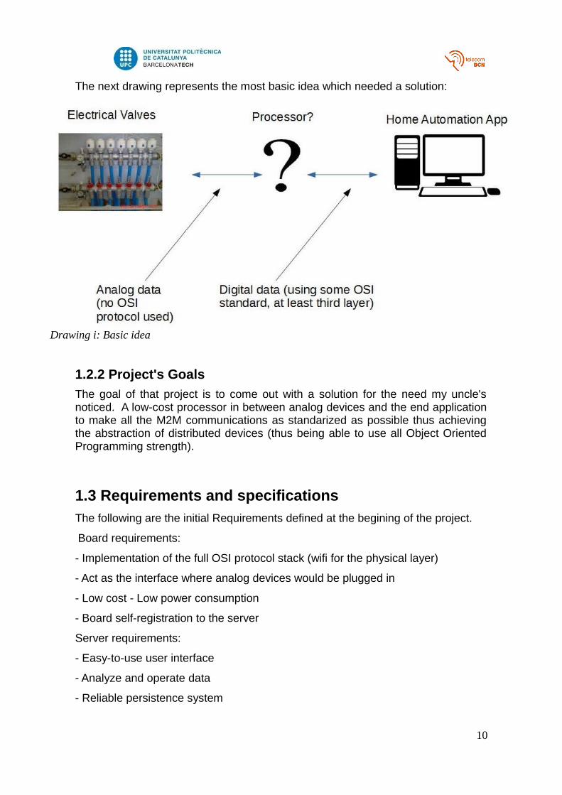
The next drawing represents the most basic idea which needed a solution:
1.2.2 Project's Goals
The goal of that project is to come out with a solution for the need my uncle'snoticed. A low-cost processor in between analog devices and the end applicationto make all the M2M communications as standarized as possible thus achievingthe abstraction of distributed devices (thus being able to use all Object OrientedProgramming strength).
1.3 Requirements and specifications
The following are the initial Requirements defined at the begining of the project.
Board requirements:
- Implementation of the full OSI protocol stack (wifi for the physical layer)
- Act as the interface where analog devices would be plugged in
- Low cost - Low power consumption
- Board self-registration to the server
Server requirements:
- Easy-to-use user interface
- Analyze and operate data
- Reliable persistence system
10
Drawing i: Basic idea
- Should hide M2M performance
Those above have not changed despite they are not very specific. What have changed due to developement ot the project are the specifications.
Elements to comply with the specifications:
Project specifications:Board:
- OSI Stack (provided by TI CC3200)- Energia (C/C++)
HTTP web server:- RESTful service
o Define URL pattern- Define start-up protocol between board and server
o Self registration of the board into the server POST all the information necessary into the server
- Functionalities reachable through GET method and query string only- No pattern applies to this software (no OOP)
Server- Symfony-based- Startup Bundle: ready to manage the startup info sent by the board and
flush it to its persistence system- Device Bundle: bundle ready to manage each device
11
2. State of the art of the technology used in thisthesis:
2.1. Internet of Things
“The connection of physical things to the Internet makes it possible to accessremote sensor data and to control the physical world from a distance. The mash-up of captured data with data retrieved from other sources, e.g., with data that iscontained in the Web, gives rise to new synergistic services that go beyond theservices that can be provided by an isolated embedded system. The Internet ofThings is based on this vision. A smart object, which is the building block of theInternet of Things, is just another name for an embedded system that isconnected to the Internet. There is another technology that points in the samedirection – the RFID technology. The RFID technology, an extension of theubiquitous optical bar codes that are found on many every-day products, requiresthe attachment of a smart low-cost electronic ID-tag to a product such that theidentity of a product can be decoded from a distance. By putting more intelligenceinto the ID tag, the tagged thing becomes a smart object. The novelty of theInternet-of-Things (IoT) is not in any new disruptive technology, but in thepervasive deployment of smart objects.” - Quoted from Real Time System writtenby Hermann Kopetz.
The aim of this document is to study a possible implementation of what HermannKopetz points out in his definition of IoT. That is, to make the low-level devicesdistributed in a home automation system smart enough to send it's data to a coremachine placed elsewhere in the internet in a high-level format. Particularly, HTTPbased messages. From now on, this distributed and smart device will be calledSmart Object (to follow Hermann's term) and the more intelligent core machinewill be called Core Server. From the view of Object Oriented Programming (OOP)and following Hermann's definition, this plus of intelligence given to the low-leveldevices transforms the idea of device into the idea of an object (referred to OOPcoding environment). That means that the coding of an application where suchSmart Objects are used comes to meet all the OOP paradigms, as we will talkabout objects from now on, such abstraction, encapsulation, inheritance andpolymorphism.
2.2. RESTful servicesWeb services are becoming really popular because they are fully oriented tonetwork-based applications. They are commonly used to hold http servers with awide range of functionalities. Nowadays, there are two schemes of web servicewhom rule the scene. The first one I want to mention, is SOAP. SOAP based web
12
services are ruled by a server-client architecture. The client of a SOAP serviceneeds to know how the server works before it is able to use it. This is done via anXML called Web Services Description Language (WSDL), where all the actionsand methods the server can perform are described, making it possible to the clientto connect to the service and gather its resources. SOAP was not chosen for thisproject due to its implementation complexity.
The second web service schema and the one that fits the simplicity needed forthis project is Representational State Transfer (REST) service. Its architecturewas designed and first drew by Roy Thomas Fielding in his Doctoral thesisArchitectural Styles and the Design of Network-based Software Architectures. Outfrom Roy words, and this is my own interpretation, REST services are ideal toemulate a data base. So, it is like a database built on top of HTTP (applicationlayer) and that is why its use is growing exponentially.
A REST service which follows Roy's rules (which are actually assumed as astandard) may store resources, or as he says, Data Element.
As in any application which stores data this way, CRUD (Create, Read, Update,Delete) methods are needed. In the case of REST services, to keep them assimple as possible, those actions can be performed with the native HTTPmethods (POST, GET, PUT, DELETE) respectively.
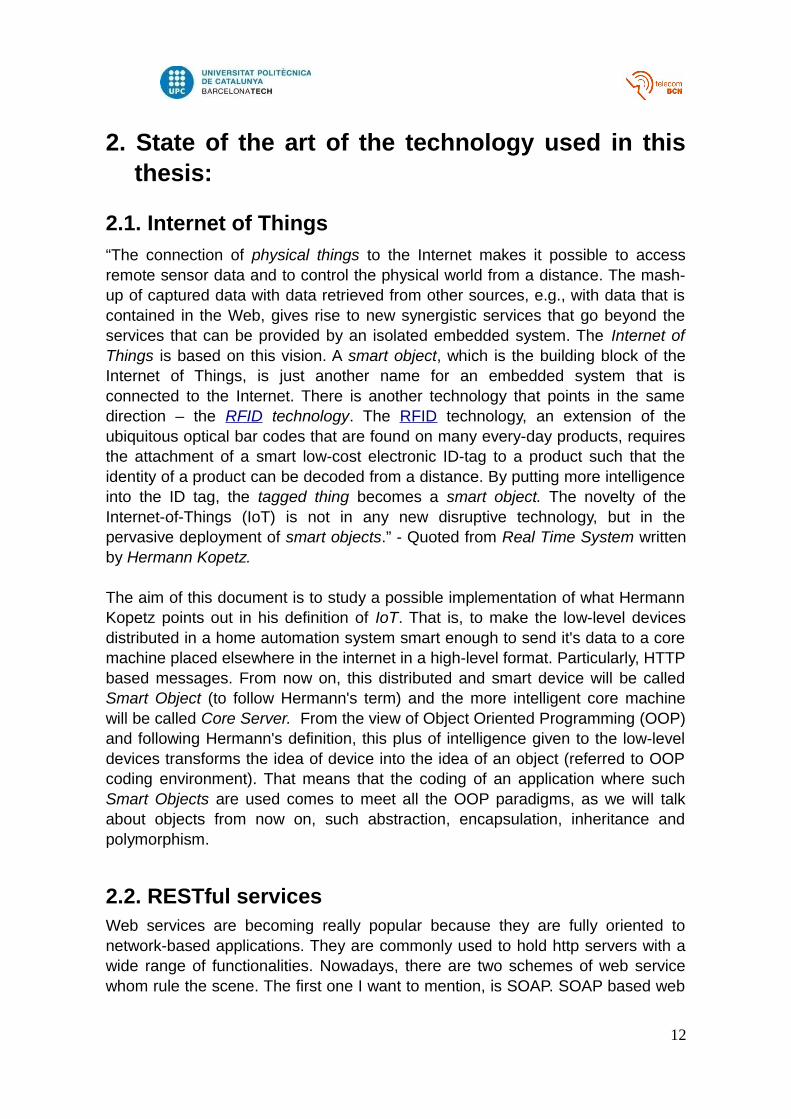
Now, to understand the way REST is used in this document, lets have a look athow Roy defines a Data Element and its attributes.
The following table was extracted from his thesis.
As we can see, each Data Element stored by a REST service provider must bepointed by an identifier, and as we can also see, this identifier is an URL. I givenow a little example on how to use this identifiers.
13
Drawing ii: Data element definition
Imagine we want to store people in a REST service, and we idenitfy each personby an URL, for example:
Roy → http://service:80/people/roy
Once we perform a GET (read) method over this URL, we will get a responsefrom the server and that would finish the interaction. In the response we will get,apart from the data itself, which format has been used to code the data (mostcommon are JSON and XML). So we only need a parser prepared to decode thisformat to get the data back.
In the Roy's REST architecture, as we only need to perform CRUD actions, theURLs used in such a service might not contain any verb. I mean, the action isperformed via the HTTP method, and the URL is just the identifier which theaction will be performed to.
This project is REST based but doesn't follow Roy's standard. The reason why wedepart from the standard can be explained with a simple example (which is just atouch of what is going to be explained in latter parts of the document).
Imagine now we have got a relay turned into a Smart Object capable ofconnecting to the internet and holding a web server. Next, we define that a relayhas got only three functionalities, to be activated, to be deactivated or to berequested for its state. If we want to perform all the M2M communicationsbetween the Core Server and this relay via HTTP, it looks like a good solution toachieve this to make this relay to hold a REST service.
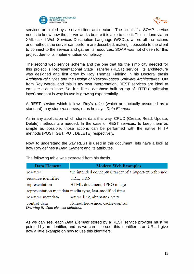
Lets see what would happen if we would not follow Roy's rules as they are exactlydefined:
At a first glance we can see this is not actually correct. The only action that wouldbe under Roy's approval would be the first one, because the action (read) isperformed directly from the http method GET and the response contains a simpleinformation (does not matter its format at this point).
The others are not correct, because they are not pointing to a Data Resourceexplicitly, they point actions which the device holding the service can perform. Itdoes not even fit the Data Resource definition, so, this may not be considered asa bad practice (in terms of Roy's rules) in this particular case.
14
Drawing iii: REST bad practice
HTTP method Resource Identifier PurposeGET relay http://relay:port/id/info Retrieves information about the relay's stateGET activate relay http://relay:port/id/activate Activates the relayGET deactivate relay http://relay:port/id/deactivate Deactivates the relay
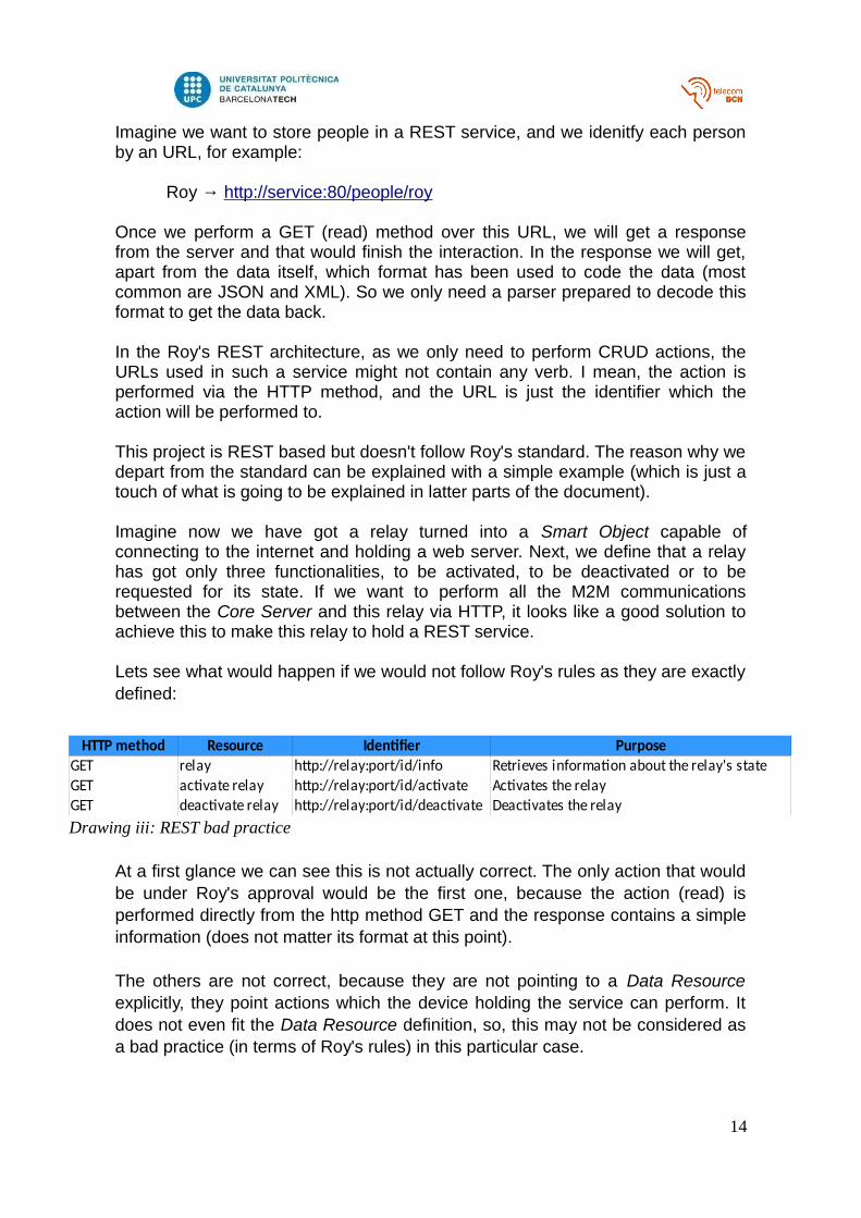
There is actually a way to perform the same actions following Roy's rules, butadds complexity to the distributed device (the relay in this example) and alsomakes the URLs a little bit more complicated. The following table shows how toperform the described actions using HTTP's query string.
With this method we would not break any rule as the action (READ) maintains thesame for the three URLs, but the latter two have got a parameters passed via thequery string, and that is totally allowed in Roy's pseudo-standard.
To conclude, the project will not be developed following those rules as the SmartObjects does not actually fit the Resource Data definition. The project will bedeveloped as explained in the first part of the former example.
2.3. PHPPHP is a wide-spread scripting language. It is an interpreted language andbecame real popular in server-side applications due to its simplicity to code andits availability to be mixed up with HTML code, reason why it became popularamong web applications developers.
This language has grown without the hold of a company, it all comes out from acommunity which has written libraries for almost any application you can think of.That is one reason I have chosen it, it is a great pennant of what Free and OpenSource Software (FOSS) means. Despite that, nowadays, it is not only a scriptinglanguage, as it can be used in OOP coding. In my opinion, its rival has alwaysbeen Java, but there are lots of programming languages which can perform therequirements of almost any application (Ruby, Python, C++, C#, etc).
2.4. SymfonySymfony is the real reason why PHP was chosen for this project. It is a frameworkdeveloped by a French company called Sensio Labs. It is open source andimplements the Model-View-Controller programming pattern for its applications.
It actually implements a slightly customized version of the Model-View-Controllerpattern.
First, a little review on what MVC coding pattern aims.
15
Drawing iv: REST good practice
HTTP method Resource Identifier PurposeGET relay http://relay:port/id Retrieves information about the relay's stateGET activate relay http://relay:port/id?action=activate Activates the relayGET deactivate relay http://relay:port/id?action=deactivate Deactivates the relay
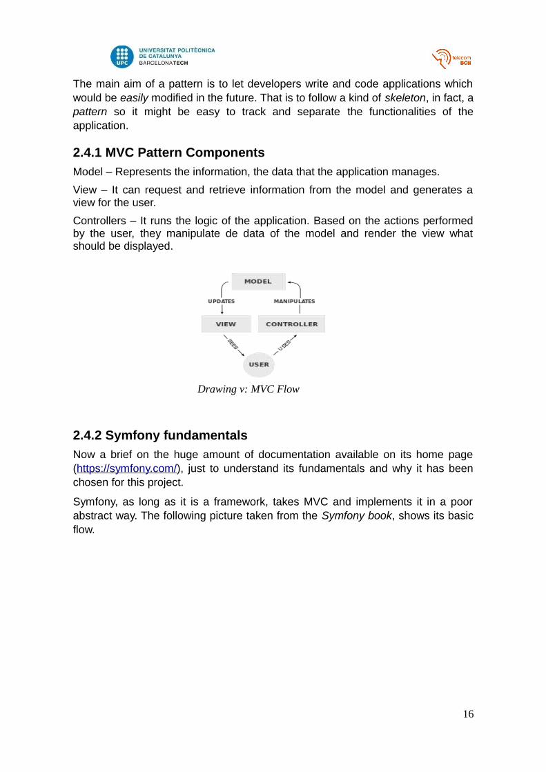
The main aim of a pattern is to let developers write and code applications whichwould be easily modified in the future. That is to follow a kind of skeleton, in fact, apattern so it might be easy to track and separate the functionalities of theapplication.
2.4.1 MVC Pattern Components
Model – Represents the information, the data that the application manages.
View – It can request and retrieve information from the model and generates aview for the user.
Controllers – It runs the logic of the application. Based on the actions performedby the user, they manipulate de data of the model and render the view whatshould be displayed.
2.4.2 Symfony fundamentals
Now a brief on the huge amount of documentation available on its home page(https://symfony.com/), just to understand its fundamentals and why it has beenchosen for this project.
Symfony, as long as it is a framework, takes MVC and implements it in a poorabstract way. The following picture taken from the Symfony book, shows its basicflow.
16
Drawing v: MVC Flow
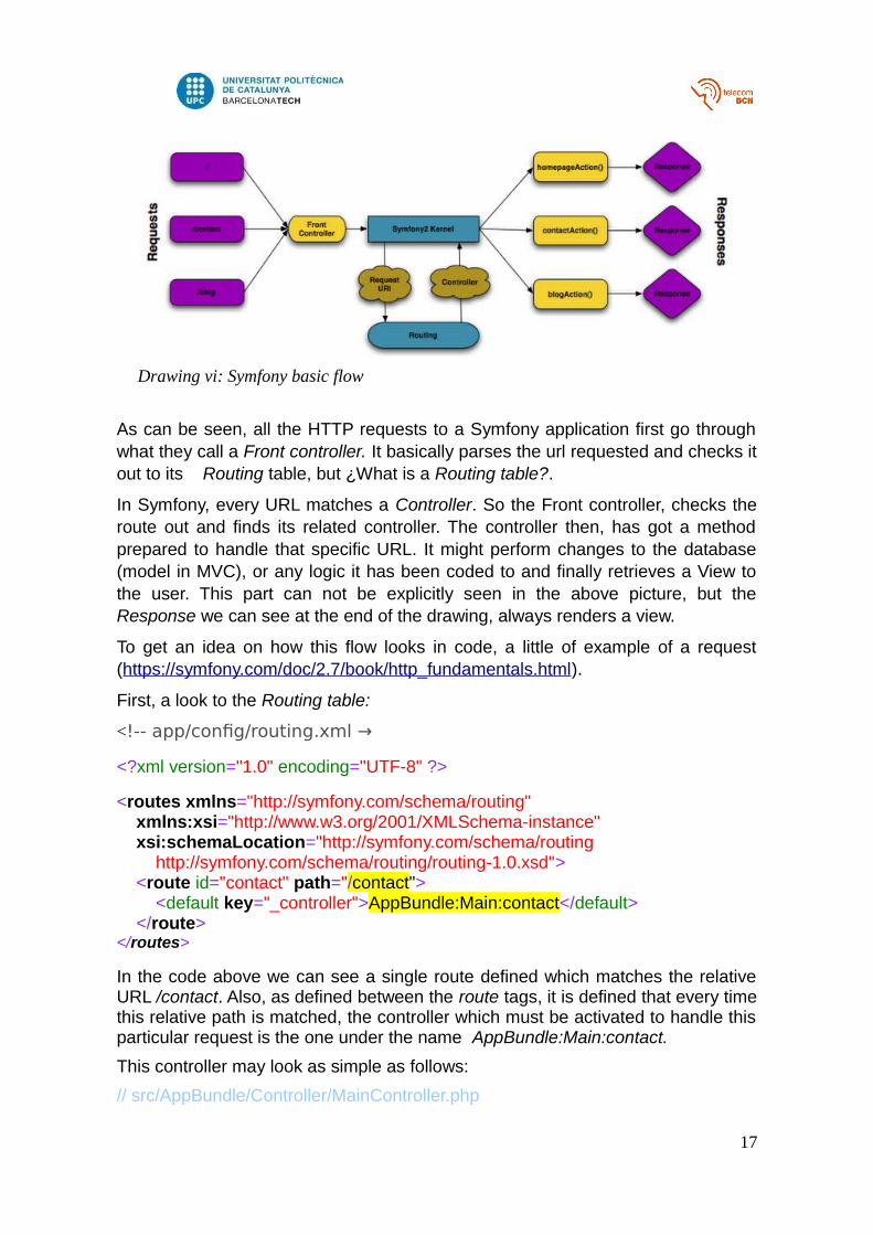
As can be seen, all the HTTP requests to a Symfony application first go throughwhat they call a Front controller. It basically parses the url requested and checks itout to its Routing table, but ¿What is a Routing table?.
In Symfony, every URL matches a Controller. So the Front controller, checks theroute out and finds its related controller. The controller then, has got a methodprepared to handle that specific URL. It might perform changes to the database(model in MVC), or any logic it has been coded to and finally retrieves a View tothe user. This part can not be explicitly seen in the above picture, but theResponse we can see at the end of the drawing, always renders a view.
To get an idea on how this flow looks in code, a little of example of a request(https://symfony.com/doc/2.7/book/http_fundamentals.html).
First, a look to the Routing table:
<!-- app/config/routing.xml →
<?xml version="1.0" encoding="UTF-8" ?>
<routes xmlns="http://symfony.com/schema/routing" xmlns:xsi="http://www.w3.org/2001/XMLSchema-instance" xsi:schemaLocation="http://symfony.com/schema/routing http://symfony.com/schema/routing/routing-1.0.xsd"> <route id="contact" path="/contact"> <default key="_controller">AppBundle:Main:contact</default> </route></routes>
In the code above we can see a single route defined which matches the relativeURL /contact. Also, as defined between the route tags, it is defined that every timethis relative path is matched, the controller which must be activated to handle thisparticular request is the one under the name AppBundle:Main:contact.
This controller may look as simple as follows:
// src/AppBundle/Controller/MainController.php
17
Drawing vi: Symfony basic flow
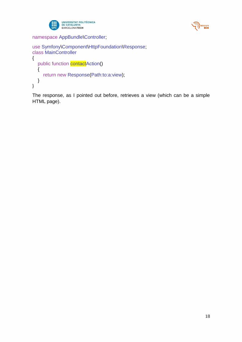
namespace AppBundle\Controller;
use Symfony\Component\HttpFoundation\Response;class MainController{ public function contactAction() { return new Response(Path:to:a:view); }}
The response, as I pointed out before, retrieves a view (which can be a simpleHTML page).
18
2.4.2.1 Bundles
The last term I think is important to understand why Symfony has been chosen, isthe Bundle concept.
The working flow of Symfony belong to its core. A Symfony developer may diveinto the implementation of its front controller its libraries and all the stuff thatmakes all the framework's flow explained before possible, but it is not a need touse this tool.
So, ¿When does a developer take action in a Symfony application? The answer isindeed, writing bundles.
A bundle is a set of resources fed from Symfony libraries which contains specificControllers, Routes and Views. It could be seen as a little application insideSymfony, There is a huge amount of third-party bundles which people develop toreach specific needs.
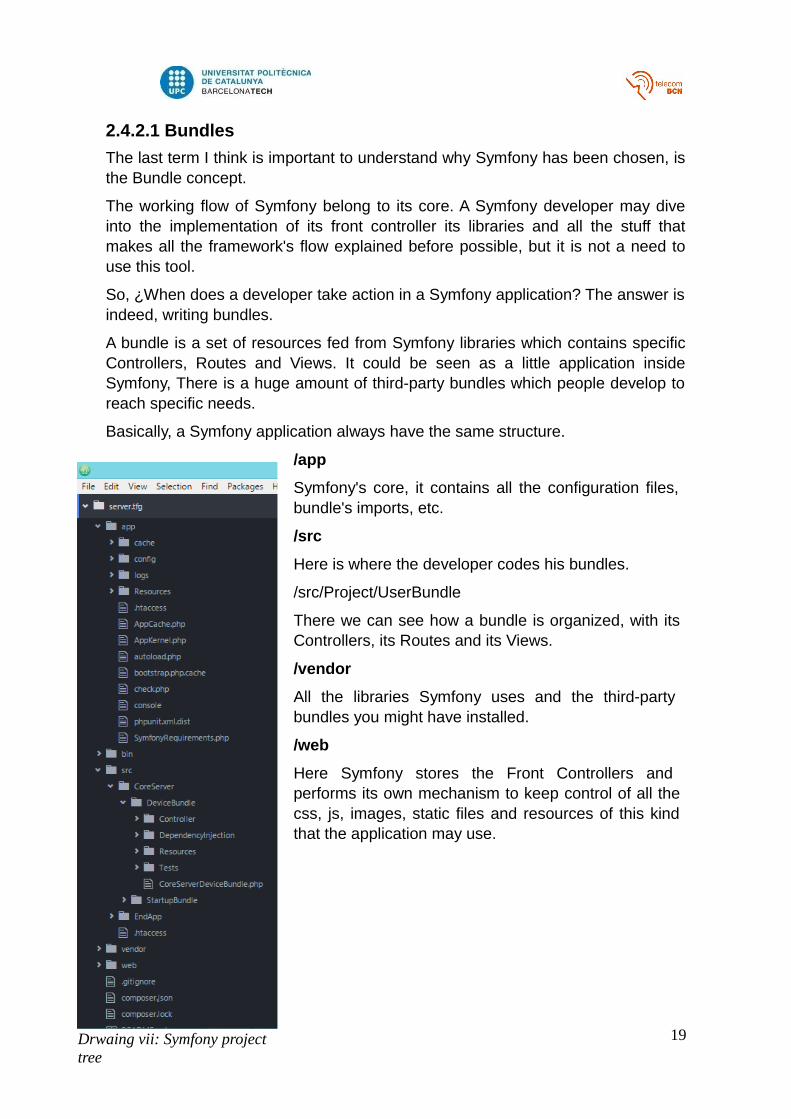
Basically, a Symfony application always have the same structure.
/app
Symfony's core, it contains all the configuration files, bundle's imports, etc.
/src
Here is where the developer codes his bundles.
/src/Project/UserBundle
There we can see how a bundle is organized, with its Controllers, its Routes and its Views.
/vendor
All the libraries Symfony uses and the third-party bundles you might have installed.
/web
Here Symfony stores the Front Controllers and performs its own mechanism to keep control of all the css, js, images, static files and resources of this kind that the application may use.
19Drwaing vii: Symfony project tree
So a bundle is a separated portion of code implementation with its own routes andcontrollers. Once you have got your bundle written down, you just have to tellSymfony that it must be included in the whole application flow. In the main Routingtable (/app directory) you must import your Bundle's routes. Finally, you must addyour bundle to the AppKernel php class (/app directory) and the bundle willbecome fully operational.
This provides a huge load of felxibility to the application because it is pretty easyto add or remove bundles. In the following chapter we will show how to takeadvantage of this tool in this project.
2.4.2.2 Doctrine
Doctrine is the database engine which links the persistence system (database)with the Symfony application. It is written in PHP and can be used absolutelydettached of Symfony, but as long as it is developed by the same company, itcomes with Symfony by default. I do mention it because it is going to be theengine to interact with the Core Server database.
2.4.2.2.1 DAO Pattern
Doctrine uses the Data Access Object pattern to make it able to the application totreat database tables as if they were regular OOP classes. Those interfaceclasses which map the database resources with the object the application willeventually use are called Entities.
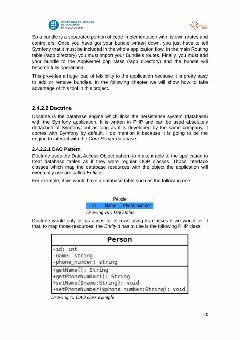
For example, if we would have a database table such as the following one:
Doctrine would only let us acces to its rows using its classes if we would tell itthat, to map those resources, the Entity it has to use is the following PHP class:
20
Drawing viii: DAO table
PeopleID Name Phone number
Drawing ix: DAO class example
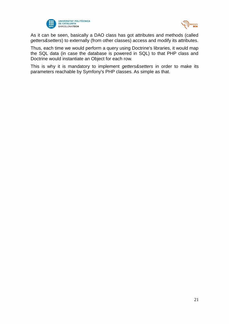
As it can be seen, basically a DAO class has got attributes and methods (calledgetters&setters) to externally (from other classes) access and modify its attributes.
Thus, each time we would perform a query using Doctrine's libraries, it would mapthe SQL data (in case the database is powered in SQL) to that PHP class andDoctrine would instantiate an Object for each row.
This is why it is mandatory to implement getters&setters in order to make itsparameters reachable by Symfony's PHP classes. As simple as that.
21
3. Project developementThrough this chapter, I am going to explain the developement and implementationof what I considered the two main roles in the proposed infrastructure. The firstone is Smart Object, which is the distributed device. Here I will define whichrequirements should accomplish those devices to work properly with my definitionof Core Server. When I'll come to explain my proposal of implementation, I wouldlike to settle that it is just that, a particular implementation, meaning that anydevice fulfilling those requirements would work properly no matter the language itis written with. Thus, adding flexibility to the whole enviroment (or infrastructure).
The second role is the Core Server, which will manage those devices from theserver-side. In this case it is not possible to be as flexible as in the Smart Objectrole, as long as only the bundles written in PHP using Symfony will be able towork with this Core Server. The flexibility remains the main goal, providing thatSymfony is concieved to be flexible itself.
The last part of the chapter shows a simple implementation of what might beconsidered as an example of end-user application. It is a simple web page (codedusing Symfony) which lists all the devices and permits the proper actions withthem.
3.1 Smart ObjectThis term comes from the Internet of Things verbose. What this project is seeking,is to try to abstract a particular device implementation and to be able to use it as aregular OOP object, making it possible to communicate with it through a high-levelprotocol, in this case, HTTP.
In order to make this system capable of managing any low-level device we foundit necessary to define a model for the smart objects suitable for any device.
3.1.1 Data model
After looking for the specifications of several devices, and here the vasteexperience of my professor was unestimable, we concluded that, no matter whatthe device is, it always can be classified following the next properties:
A device can be..
ACTIVATABLE
Those which can be forced to change their state. The activate action is performedby the Core Server.
LAUNCHER
Those which are able to launch events when their state changes. The statechange does not come from the Core Server. Thus, it may be an opened window,an opened door, a light sensor, etc.
READABLE
Those who respond some data when are asked for it.
22
A part from that, a device can manage the following data models:
BINARY
The device is only capable of managing two values.
FINITE
The device is capable of managing a finite range of values (from 0..n-1).
CONTINUOUS
The device can manage any value between a Max and a Min.
Thus, any time we would like to add a particular device to this system, it would bemandatory to do the job of classifying it in this patterns. With that, it is possible tosettle the specifications of a Smart Object.
3.1.1 Smart Object Requirements
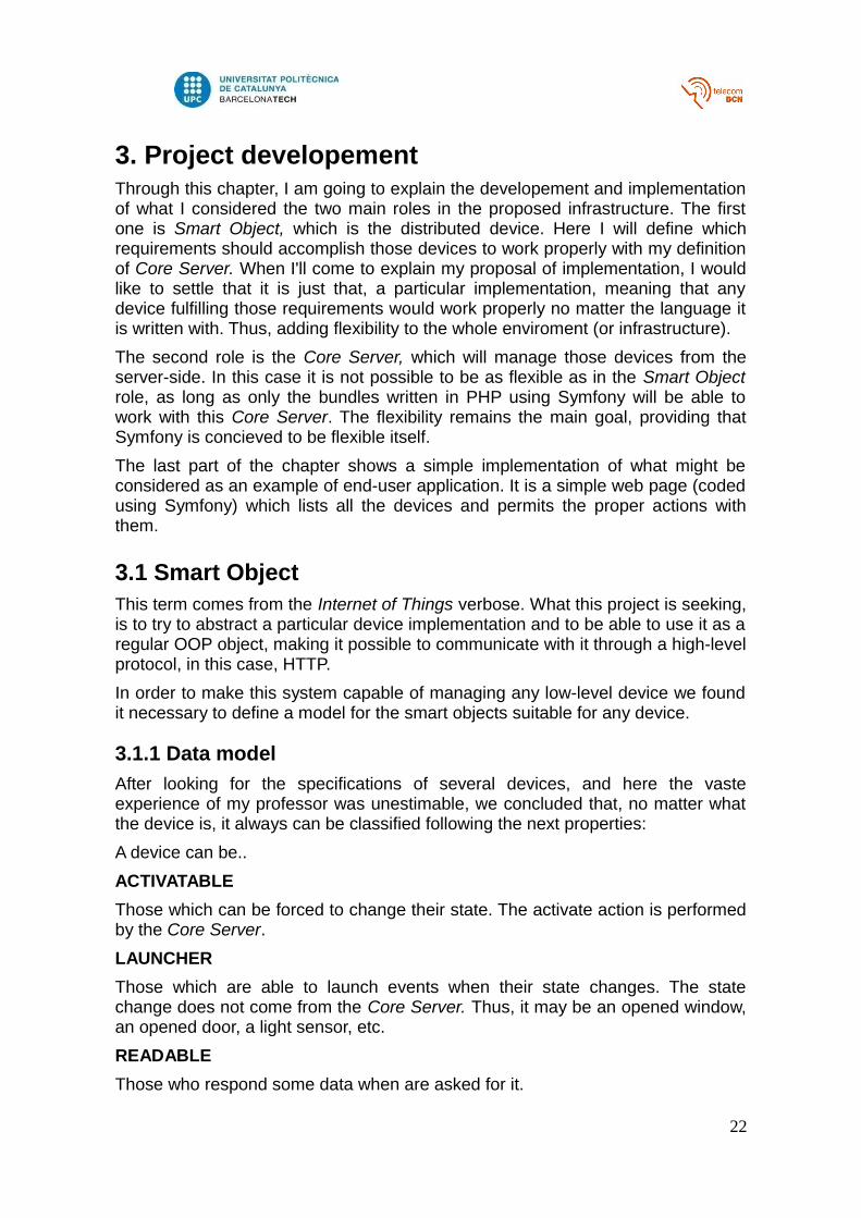
From the point of view of OOP, an Smart Object looks as follows:
All of the parameters are typed as String just because the data in the M2M communications Smart Object – Core Server will be sent through HTTP query string.
3.1.1.1 Startup requirements
Every Smart Object, when it has got internet connection, must connect to theCore Server it has defined to work with and send some parameters. Thoseparamteres should be encoded as a POST request and sended to the CoreServer via a HTML form.
To get a bit deeper on how a Smart Object works, we have to take into accountthat a device does not become smart magically. It must exist a processor between
23
Drawing x: SMOB class
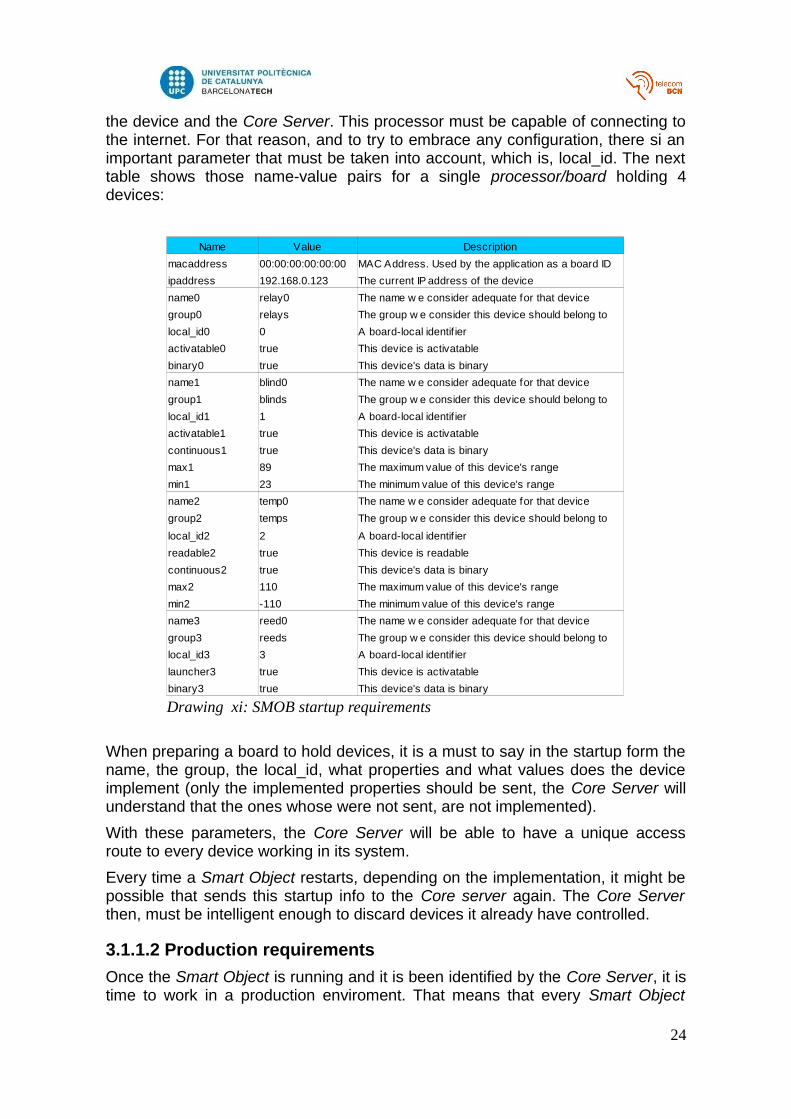
the device and the Core Server. This processor must be capable of connecting tothe internet. For that reason, and to try to embrace any configuration, there si animportant parameter that must be taken into account, which is, local_id. The nexttable shows those name-value pairs for a single processor/board holding 4devices:
When preparing a board to hold devices, it is a must to say in the startup form thename, the group, the local_id, what properties and what values does the deviceimplement (only the implemented properties should be sent, the Core Server willunderstand that the ones whose were not sent, are not implemented).
With these parameters, the Core Server will be able to have a unique accessroute to every device working in its system.
Every time a Smart Object restarts, depending on the implementation, it might bepossible that sends this startup info to the Core server again. The Core Serverthen, must be intelligent enough to discard devices it already have controlled.
3.1.1.2 Production requirements
Once the Smart Object is running and it is been identified by the Core Server, it istime to work in a production enviroment. That means that every Smart Object
24
Drawing xi: SMOB startup requirements
Name Value Description
macaddress 00:00:00:00:00:00 MAC Address. Used by the application as a board ID
ipaddress 192.168.0.123 The current IP address of the device
name0 relay0 The name w e consider adequate for that device
group0 relays The group w e consider this device should belong to
local_id0 0 A board-local identif ier
activatable0 true This device is activatable
binary0 true This device's data is binary
name1 blind0 The name w e consider adequate for that device
group1 blinds The group w e consider this device should belong to
local_id1 1 A board-local identif ier
activatable1 true This device is activatable
continuous1 true This device's data is binary
max1 89 The maximum value of this device's range
min1 23 The minimum value of this device's range
name2 temp0 The name w e consider adequate for that device
group2 temps The group w e consider this device should belong to
local_id2 2 A board-local identif ier
readable2 true This device is readable
continuous2 true This device's data is binary
max2 110 The maximum value of this device's range
min2 -110 The minimum value of this device's range
name3 reed0 The name w e consider adequate for that device
group3 reeds The group w e consider this device should belong to
local_id3 3 A board-local identif ier
launcher3 true This device is activatable
binary3 true This device's data is binary
must be capable of running a HTTP server, but to act as a HTTP client too.
3.1.1.2.1 Smart Object URL pattern action
The particular funcionalities of any Smart Object must be reachable following thenext URL pattern:
http://smart_object_ip:port/local_id/action
3.1.1.2.2 Smart Object URL pattern with parameters
If for any reason, the action to be performed by the object has got anyparameters, those must be attached in the request using the query string. Thus,an action with two parameters should look like this:
http://smart_object_ip:port/local_id/action?param1=value1¶m2=value2
3.1.1.2.2 Smat Object URL for network cofinguration
Apart from its functionalities,four network parameters need to be set for an object;ip address, gateway ip, dns server and network mask and also the transport portused to hold the HTTP server.
These information, will be sent by the Core String attached to the GET requestusing the query string. Here is an example of what an URL to configure thenetwork parameters of a given Smart Object should look:
http://smart_object_ip:port/netConf?ip=xxx.xxx.xxx.xxx&gateway=xxx.xxx.xxx.xxx&dnsxx.xxx.xxx.xxx&maskxx.xxx.xxx&port=xxxx
25
3.1.2 Proposal of Implementation
Once the requirements for those Smart Objects are settled down, I explain aproposal of implementation.
For this part I had several options in mind. What I would have loved, is to be ableto write the code for an object in a high level programming language such as PHPor Java, due to its amount of libraries and easy to understand code. Unfortunately,the processors embedded in the boards used for IoT, are Cortex M4 based, whichis actually comprehensible due to its low resources consumption and fast andsimple performance. Thus, no high-level programming language was available.
The second alternative I thought of was raw C. I discarded that quickly because,as we know, C is an structured language. Thus it is not flexible enough for me, aslong as this is a proposal of implementation, I would not spend the time requiredto develop a HTTP server capable of parse and send request with query stringparameters.
My choice was finally Energia. Energia is an Arduino-based integrateddevelopment enviroment (IDE) created by Texas Instruments. In the tests for thisproject a CC3200 demonstration board was used, so it seems obvious to useEnergia. Also, Arduino works with two pieces of code, the setup and the loop, factthat suits the Smart Object requirements ideally. Now I explain how.
3.1.2.3 Implementation using Energia
3.1.2.3.1 Setup
If we have a look at the startup requirements, it easy to think about this part ofArduino coding to fulfill the specifications.
In this part of the code, the board must get an internet connection (via DHCP ordefining the network parameters stragiht in the code) and send the informationrequired to the Core Server. In general and abstract terms this setup code wouldlook as shown in the ANNEX I.
3.1.2.3.2 Loop
This part of the code will perform the production requirements explained before.The code can be found in the ANNEX I as well.
26
3.2 Core ServerWe have seen the first role of the two main roles that the whole applicationenviroment has got. I would like to settle, and to clearify, that what I define asCore Server is NOT the application itself, but is a kind of interface that makesavailable to the final home automation application developer the access andcontrol of the resources (in this case, the Smart Objects). As the chosendeveloping enviroment is Symfony, that means that the final application wouldneed to install all the Bundles that pool the Core Server.
3.2.1 Working flow
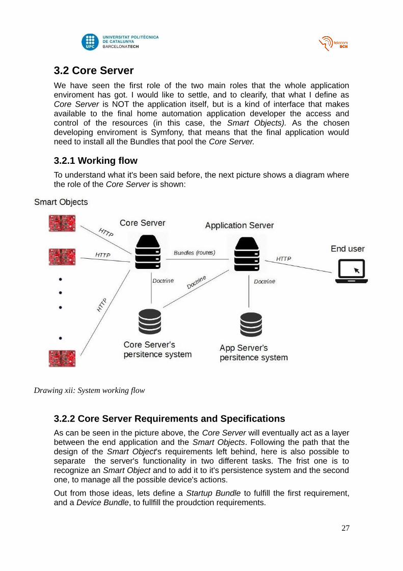
To understand what it's been said before, the next picture shows a diagram wherethe role of the Core Server is shown:
3.2.2 Core Server Requirements and Specifications
As can be seen in the picture above, the Core Server will eventually act as a layerbetween the end application and the Smart Objects. Following the path that thedesign of the Smart Object's requirements left behind, here is also possible toseparate the server's functionality in two different tasks. The frist one is torecognize an Smart Object and to add it to it's persistence system and the secondone, to manage all the possible device's actions.
Out from those ideas, lets define a Startup Bundle to fulfill the first requirement,and a Device Bundle, to fullfill the proudction requirements.
27
Drawing xii: System working flow
3.2.2.1 Startup Bundle
Lets notice that the Application using this enviroment, will not know nor have anyreference to this StartupBundle (apart from installing and enabling it, of course).This will not be the same in the case of the DeviceBundle, which will have toenable references in order to make it available for the Application the access andmanagement of each device.
Now talking about the StartupBundle. As it has got only one functionalitiy (torecognize and add new devices to its persistence system, if necessary), it will onlyneed one route (the one the Smart Objects requests for at startup), one Controller(which will implement the logic of adding it or not) and no view at all, as no userneeds to see anything out from this process.
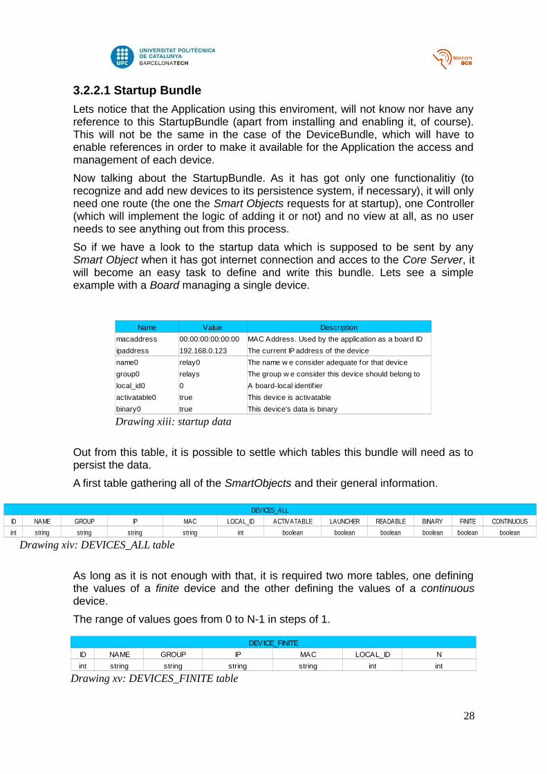
So if we have a look to the startup data which is supposed to be sent by anySmart Object when it has got internet connection and acces to the Core Server, itwill become an easy task to define and write this bundle. Lets see a simpleexample with a Board managing a single device.
Out from this table, it is possible to settle which tables this bundle will need as topersist the data.
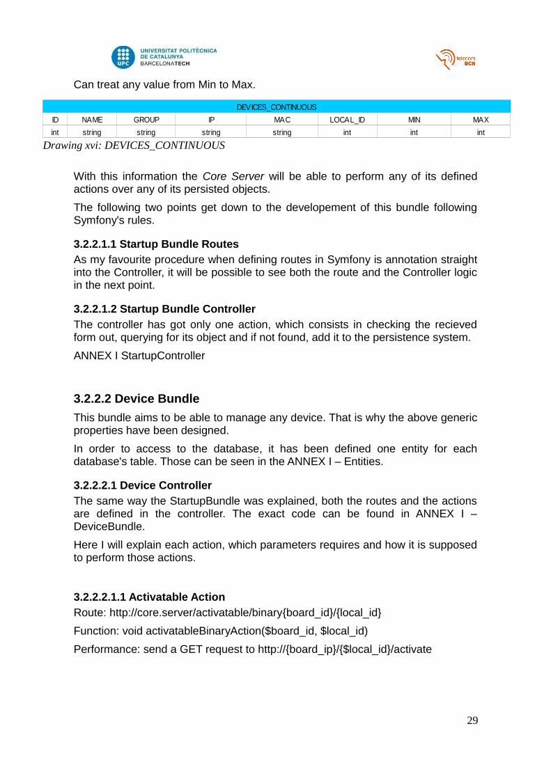
A first table gathering all of the SmartObjects and their general information.
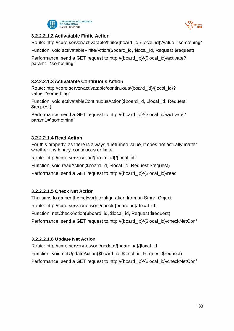
As long as it is not enough with that, it is required two more tables, one definingthe values of a finite device and the other defining the values of a continuousdevice.
The range of values goes from 0 to N-1 in steps of 1.
28
Drawing xiii: startup data
Name Value Description
macaddress 00:00:00:00:00:00 MAC Address. Used by the application as a board ID
ipaddress 192.168.0.123 The current IP address of the device
name0 relay0 The name w e consider adequate for that device
group0 relays The group w e consider this device should belong to
local_id0 0 A board-local identif ier
activatable0 true This device is activatable
binary0 true This device's data is binary
Drawing xiv: DEVICES_ALL table
DEVICES_ALL
ID NAME GROUP IP MAC LOCAL_ID ACTIVATABLE LAUNCHER READABLE BINARY FINITE CONTINUOUS
int string string string string int boolean boolean boolean boolean boolean boolean
Drawing xv: DEVICES_FINITE table
DEVICE_FINITE
ID NAME GROUP IP MAC LOCAL_ID N
int string string string string int int
Can treat any value from Min to Max.
With this information the Core Server will be able to perform any of its definedactions over any of its persisted objects.
The following two points get down to the developement of this bundle followingSymfony's rules.
3.2.2.1.1 Startup Bundle Routes
As my favourite procedure when defining routes in Symfony is annotation straightinto the Controller, it will be possible to see both the route and the Controller logicin the next point.
3.2.2.1.2 Startup Bundle Controller
The controller has got only one action, which consists in checking the recievedform out, querying for its object and if not found, add it to the persistence system.
ANNEX I StartupController
3.2.2.2 Device Bundle
This bundle aims to be able to manage any device. That is why the above genericproperties have been designed.
In order to access to the database, it has been defined one entity for eachdatabase's table. Those can be seen in the ANNEX I – Entities.
3.2.2.2.1 Device Controller
The same way the StartupBundle was explained, both the routes and the actionsare defined in the controller. The exact code can be found in ANNEX I –DeviceBundle.
Here I will explain each action, which parameters requires and how it is supposedto perform those actions.
3.2.2.2.1.1 Activatable Action
Route: http://core.server/activatable/binary{board_id}/{local_id}
Function: void activatableBinaryAction($board_id, $local_id)
Performance: send a GET request to http://{board_ip}/{$local_id}/activate
29
Drawing xvi: DEVICES_CONTINUOUS
DEVICES_CONTINUOUS
ID NAME GROUP IP MAC LOCAL_ID MIN MAX
int string string string string int int int
3.2.2.2.1.2 Activatable Finite Action
Route: http://core.server/activatable/finite/{board_id}/{local_id}?value="something"
Function: void activatableFiniteAction($board_id, $local_id, Request $request)
Performance: send a GET request to http://{board_ip}/{$local_id}/activate?param1="something"
3.2.2.2.1.3 Activatable Continuous Action
Route: http://core.server/activatable/continuous/{board_id}/{local_id}?value="something"
Function: void activatableContinuousAction($board_id, $local_id, Request $request)
Performance: send a GET request to http://{board_ip}/{$local_id}/activate?param1="something"
3.2.2.2.1.4 Read Action
For this property, as there is always a returned value, it does not actually matter whether it is binary, continuous or finite.
Route: http://core.server/read/{board_id}/{local_id}
Function: void readAction($board_id, $local_id, Request $request)
Performance: send a GET request to http://{board_ip}/{$local_id}/read
3.2.2.2.1.5 Check Net Action
This aims to gather the network configuration from an Smart Object.
Route: http://core.server/network/check/{board_id}/{local_id}
Function: netCheckAction($board_id, $local_id, Request $request)
Performance: send a GET request to http://{board_ip}/{$local_id}/checkNetConf
3.2.2.2.1.6 Update Net Action
Route: http://core.server/network/update/{board_id}/{local_id}
Function: void netUpdateAction($board_id, $local_id, Request $request)
Performance: send a GET request to http://{board_ip}/{$local_id}/checkNetConf
30
3.2.3 Implementation
To explain my implementation of the Core Server I assume the host machine usedholds a LAMP (Linux, Apache, MySQL, PHP) server, that means:
1) The system is Linux-based. In this chapter Fedora 22 is used.
2) The system is running a web server. In this chapter php built-in web server isused.
3) The system has got a MariaDB/MySQL server running.
4) The system has got php installed.
All the pieces of code and references can be found in the ANNEX II. This one is afile-tree for the whole Symfony project.
3.2.3.1 Install Symfony
SensioLabs recently released a Symfony installer. That means, that with phprunning in your server and having curl installed, installing Symfony becomes aseasy as explained herehttp://symfony.com/doc/current/book/installation.html.
These are the two commands necessary:
$ sudo curl LsS http://symfony.com/installer o /usr/local/bin/symfony
As it can be seen, it already enables a command symfony in your user bin folder,with that, move to the desired directory to hold the application and execute:
$ symfony new my_project_name
I created server.tfg in my SkyDrive TFG directory:
$ cd /media/windows/Users/lucas/SkyDrive/TFG/
$ symfony new server.tfg
3.2.3.2 Generate Bundles
Symfony comes with php-written commands to manage a project. I create thefollowing bundles:
1) CoreServerDeviceBundle: already explained its functionality.
2) CoreServerStartupBundle: already explained its functionality.
3) CoreServerEntityBundle: auxiliary bundle to hold the 3 entities thatwould map to the databse.
4) EndAppHomeBundle: a simulacre on what could be an end application.Just fot test purposes.
31
Those can be created with the symfony command:
$ php app/console generate:bundle
3.2.3.3 Routing Imports
In order to be able to apply all the routes defined in the specifications chapter,there must be some changes done on each bundles routing file.
For each bundle the file is located at:
1) /server.tfg/src/CoreServer/DeviceBundle/Resources/config/routing.yml
2) /server.tfg/src/CoreServer/StartupBundle/Resources/config/routing.yml
4) /server.tfg/src/CoreServer/DeviceBundle/Resources/config/routing.yml
3.2.3.4 Configure database
As it is been explained above, I am going to use Doctrine as the DAO layer for thedatabase. Its configuration is pretty easy.
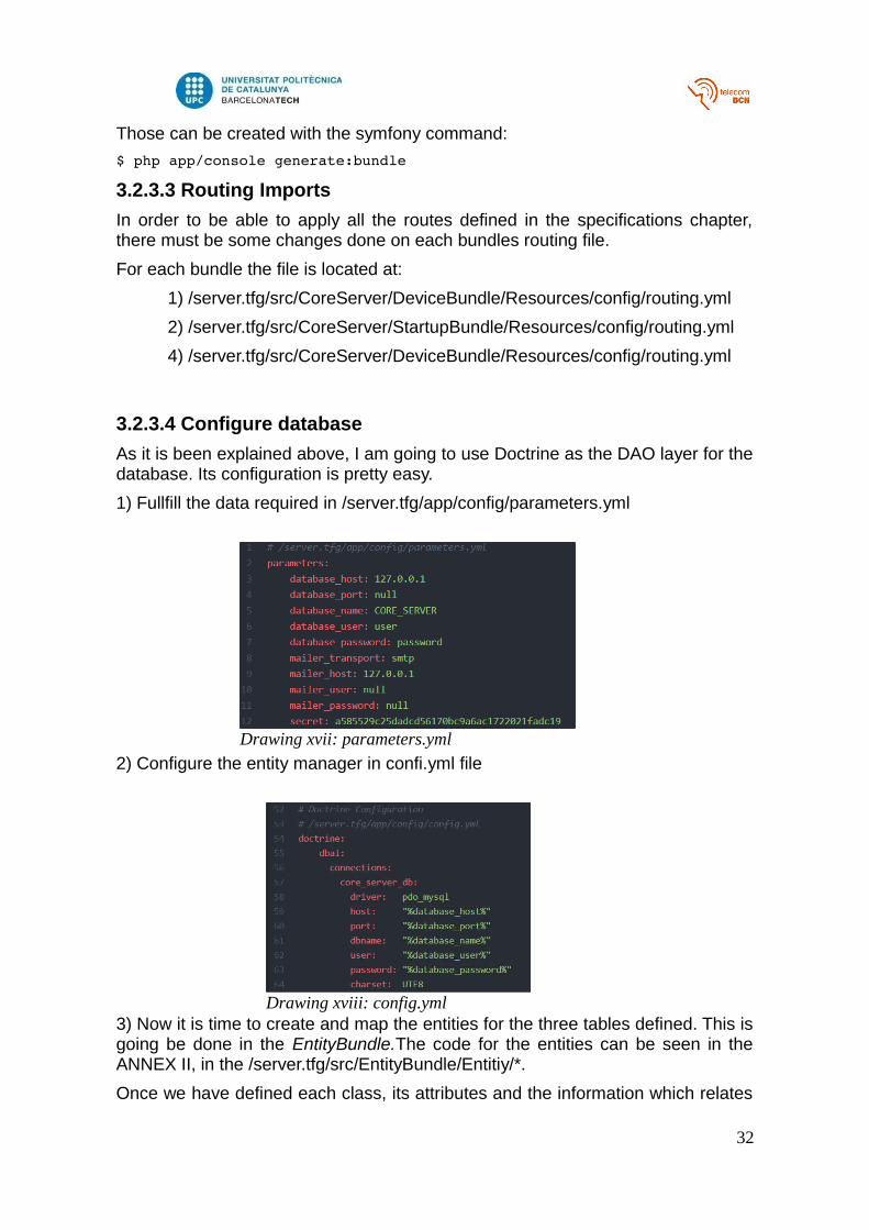
1) Fullfill the data required in /server.tfg/app/config/parameters.yml
2) Configure the entity manager in confi.yml file
3) Now it is time to create and map the entities for the three tables defined. This isgoing be done in the EntityBundle.The code for the entities can be seen in theANNEX II, in the /server.tfg/src/EntityBundle/Entitiy/*.
Once we have defined each class, its attributes and the information which relates
32
Drawing xvii: parameters.yml
Drawing xviii: config.yml
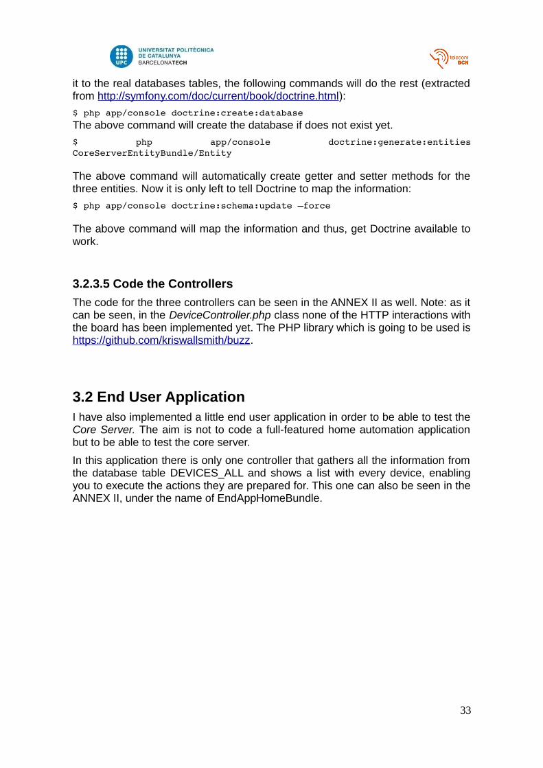
it to the real databases tables, the following commands will do the rest (extractedfrom http://symfony.com/doc/current/book/doctrine.html):
$ php app/console doctrine:create:databaseThe above command will create the database if does not exist yet.
$ php app/console doctrine:generate:entitiesCoreServerEntityBundle/Entity
The above command will automatically create getter and setter methods for thethree entities. Now it is only left to tell Doctrine to map the information:
$ php app/console doctrine:schema:update –force
The above command will map the information and thus, get Doctrine available towork.
3.2.3.5 Code the Controllers
The code for the three controllers can be seen in the ANNEX II as well. Note: as itcan be seen, in the DeviceController.php class none of the HTTP interactions withthe board has been implemented yet. The PHP library which is going to be used ishttps://github.com/kriswallsmith/buzz.
3.2 End User ApplicationI have also implemented a little end user application in order to be able to test theCore Server. The aim is not to code a full-featured home automation applicationbut to be able to test the core server.
In this application there is only one controller that gathers all the information fromthe database table DEVICES_ALL and shows a list with every device, enablingyou to execute the actions they are prepared for. This one can also be seen in theANNEX II, under the name of EndAppHomeBundle.
33
4. Results
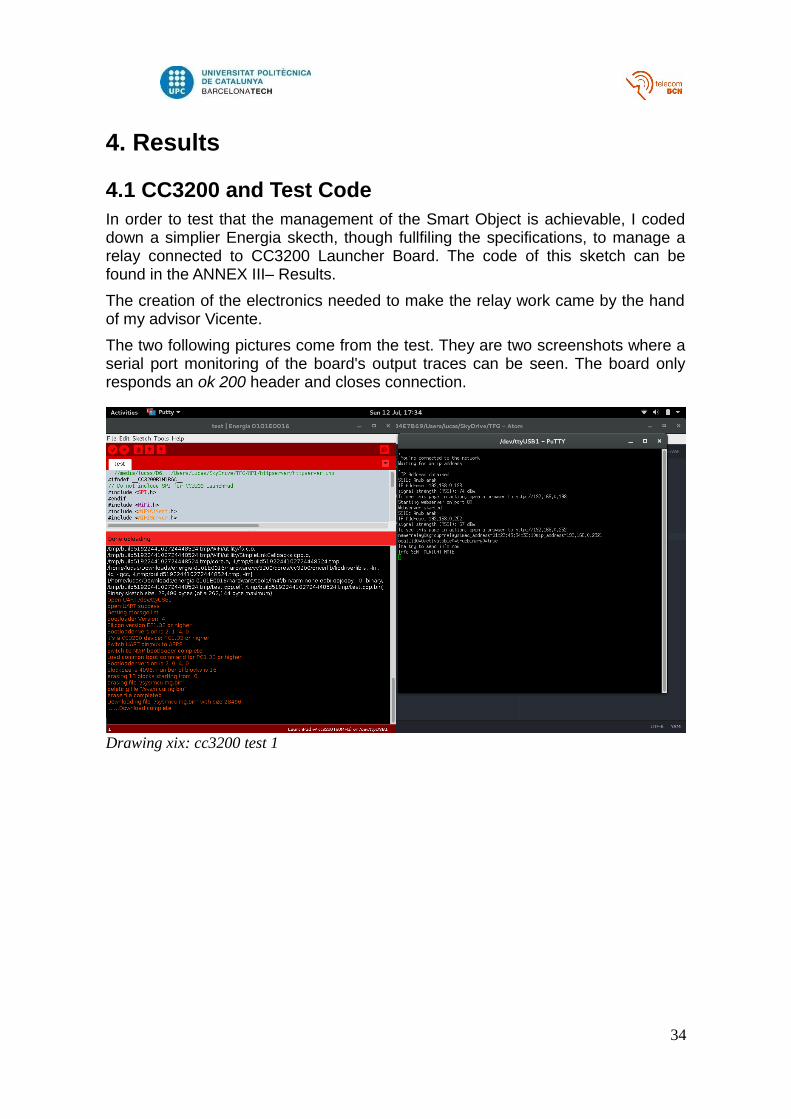
4.1 CC3200 and Test CodeIn order to test that the management of the Smart Object is achievable, I codeddown a simplier Energia skecth, though fullfiling the specifications, to manage arelay connected to CC3200 Launcher Board. The code of this sketch can befound in the ANNEX III– Results.
The creation of the electronics needed to make the relay work came by the handof my advisor Vicente.
The two following pictures come from the test. They are two screenshots where aserial port monitoring of the board's output traces can be seen. The board onlyresponds an ok 200 header and closes connection.
34
Drawing xix: cc3200 test 1
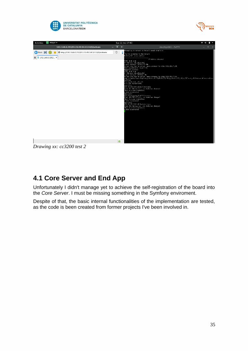
4.1 Core Server and End AppUnfortunately I didn't manage yet to achieve the self-registration of the board intothe Core Server. I must be missing something in the Symfony enviroment.
Despite of that, the basic internal functionalities of the implementation are tested,as the code is been created from former projects I've been involved in.
35
Drawing xx: cc3200 test 2
5. BudgetThis project has got cost 0. All the material used has been borrowed to theETSETB Electronical Engineering department.
5.1 Components list
The material borrowed for prototyping is:
- Texas Instruments, CC3200 LAUNCHERXL
- TE Connectivity Potter & Brumfield Relays, OJE-SS-105HM,000
5.2 Design cost
This project developement, the design and the implementation of the code hastaken for me about 10 hours/week during 20 weeks, resulting in a spent time of200 hours approximately.
5.3 Financial viability
The first thing that must be reminded is that this project is fed, and also shares,the FOSS fundamentals. Thus, its aim is not to make economical benefit out of it,but to give society a tool to be used in IoT and Home Automation enviroments.
The main distributing source shall be GitHub, and try to fork the Symfony to codea less-featured and more dedicated framework for this funciontalities.
36
6. Conclusions and future developementEvery day the world of technology evolves amizingly fast. The IoT term, webservices, content delivery networks. All of this terms come to aim the same thing,to develop tools that lets people in general to be more productive and moreefficient. To share resources among all the of the desired machines, devices,smartphones and, eventually, users. The BigData also tries to embrace themanagement of the huge loads of information produced every hour.
I do really believe that the network will eventually become a single application,more like a global operating system than a network itself. The compatiblenessamong coding languages, the APIs written for almost any need will, in my opinion,someday reach a global application. That vision of the future (or even present) isstuning. The way I see non developer users integrate technology in their lifes, theway new applications are developed in a blink of an eye, is half scaring halfamazing. I do not know if people is prepared for a world where any information isreachable in the click of a mouse, all of the devices reachable, every singleperson identified. As humaninty is not predictible, we can only wait and see whathappens.
In this project, I propose a manner to try to integrate IoT with HTTP, and thus,enable any developer to use that infraestructure to manage smart objects. I do notactually know if it is a good system, or if someday me and my uncle will deploy itto use it in a real Home Automation application, but at least I touch the criticalparts of what I consider the new paradigms nowadays. Doing a smoothbenchmarking, I noticed that what manufacturers are doing is exactly that, toconvert the analog data that a low-level device produces, process it and send it tothe world as standarized as possible. That, for a person with pesimistictendencies like, takes me to think that this project is just a waste of time, as longas I bet that some standard solution must appear in the near future.
I say that beacause I do really believe there is a need to cover in IoT. There are alot of ways of having lots of IoT devices managed by an Arduino, but there is notyet a way to be able to manage all of this straight in the application layer. If thatwould come to happen, and hopefully would be done via this project, that solutionshall rise from the community, thus using open-source resources, just like PHP. Ifany device would come to meet my requirements (among many other standarsthey actually implement), it would be an open-source alternative to manage them.I would love to also use as distributing platform services like GitHub, whereanyone can fork a project and try to improve it with his own ideas. That shouldhappen with this, as long as there is a lot of talent out there, while the basic ideais presented in this project, implementation improvements and changes could bereach by other developers.
For example, the security issue has not been treated at all. Some sort ofasymetric encryption system shall be included both in the board an the server,apart from https for example. Symfony is really secure when well programmed butthat is only between the end user and the Core Server, there is an important lackin this field when talking about the SmartObject-CoreServer communications.
37
Bibliography[1] http://symfony.com/fr/doc/current/book/index.html, Symfony Book
[2] http://www.ics.uci.edu/~fielding/pubs/dissertation/top.htm, Architectural Styles and the Design of Network-based Software Architectures, Roy Thomas Fielding, 2000.
38


![Eclipse IOT [IoT World Santa Clara]](https://img.pdfslide.us/doc/110x75/5a65c4147f8b9aa4758b6a3f/eclipse-iot-iot-world-santa-clara.jpg)