Embed Size (px)
Citation preview
©2012 DJI Innovations. All Rights Reserved. 1
iOSD (On Screen Display)
User Manual V1.4
2012-12-04
www.dji-innovations.com
©2012 DJI Innovations. All Rights Reserved. 2
Disclaimer
Thank you for purchasing product(s) from DJI Innovations. Please read the instructions carefully before
installing the hardware and software for this product, this will ensure trouble free operation of your iOSD.
Please use DJI products in accordance with the provisions of your local authorities and regulations.
As DJI Innovations has no control over use, setup, final assembly, modification (including use of
non-specified DJI parts i.e. motors, ESCs, propellers, etc.) or misuse, no liability shall be assumed nor
accepted for any resulting damage or injury. By the act of use, setup or assembly, the user accepts all
resulting liability. DJI Innovations accepts no liability for damage(s) or injured incurred directly or indirectly
from the use of this product.
DJI and iOSD is a registered trademark of DJI Innovations. Names of products, brands, etc., appearing in
this manual are trademarks or registered trademarks of their respective owner companies. This product
and manual are copyrighted by DJI Innovations with all rights reserved. No part of this product or manual
shall be reproduced in any form without the prior written consent or authorization of DJI Innovations. No
patent liability is assumed with respect to the use of the product or information contained herein.
Contents
Disclaimer .............................................................................................................................................. 2
Contents ................................................................................................................................................ 2
Introduction ............................................................................................................................................ 3
In Box .................................................................................................................................................... 4
Assembly ............................................................................................................................................... 5
Display Description ................................................................................................................................ 7
Test ....................................................................................................................................................... 9
Appendix ............................................................................................................................................. 10
Port Description ............................................................................................................................ 10
Specifications ............................................................................................................................... 11
Trouble Shooting ........................................................................................................................... 12
©2012 DJI Innovations. All Rights Reserved. 3
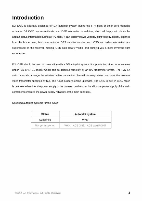
Introduction
DJI iOSD is specially designed for DJI autopilot system during the FPV flight or other aero-modeling
activates. DJI iOSD can transmit video and iOSD information in real time, which will help you to obtain the
aircraft status information during a FPV flight. It can display power voltage, flight velocity, height, distance
from the home point, horizontal attitude, GPS satellite number, etc. iOSD and video information are
superposed on the receiver, making iOSD data clearly visible and bringing you a more involved flight
experience.
DJI iOSD should be used in conjunction with a DJI autopilot system. It supports two video input sources
under PAL or NTSC mode, which can be selected remotely by an R/C transmitter switch. The R/C TX
switch can also change the wireless video transmitter channel remotely when user uses the wireless
video transmitter specified by DJI. The iOSD supports online upgrades. The iOSD is built-in BEC, which
is on the one hand for the power supply of the camera, on the other hand for the power supply of the main
controller to improve the power supply reliability of the main controller.
Specified autopilot systems for the iOSD
Status Autopilot system
Supported WKM
Not yet supported WKH、ACE ONE、ACE WAYPOINT
©2012 DJI Innovations. All Rights Reserved. 4
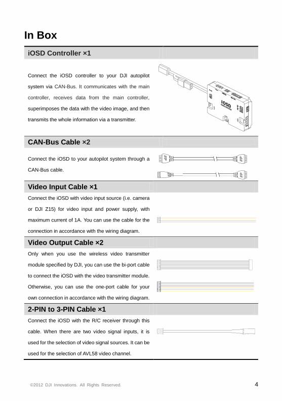
In Box
iOSD Controller ×1
Connect the iOSD controller to your DJI autopilot
system via CAN-Bus. It communicates with the main
controller, receives data from the main controller,
superimposes the data with the video image, and then
transmits the whole information via a transmitter.
CAN-Bus Cable ×2
Connect the iOSD to your autopilot system through a
CAN-Bus cable.
dJId
JI
dJId
JI
Video Input Cable ×1
Connect the iOSD with video input source (i.e. camera
or DJI Z15) for video input and power supply, with
maximum current of 1A. You can use the cable for the
connection in accordance with the wiring diagram.
Video Output Cable ×2
Only when you use the wireless video transmitter
module specified by DJI, you can use the bi-port cable
to connect the iOSD with the video transmitter module.
Otherwise, you can use the one-port cable for your
own connection in accordance with the wiring diagram.
2-PIN to 3-PIN Cable ×1
Connect the iOSD with the R/C receiver through this
cable. When there are two video signal inputs, it is
used for the selection of video signal sources. It can be
used for the selection of AVL58 video channel.
©2012 DJI Innovations. All Rights Reserved. 5
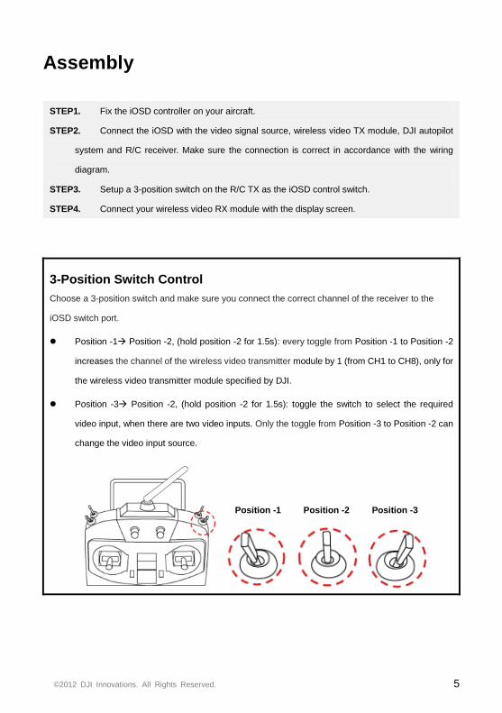
Assembly
STEP1. Fix the iOSD controller on your aircraft.
STEP2. Connect the iOSD with the video signal source, wireless video TX module, DJI autopilot
system and R/C receiver. Make sure the connection is correct in accordance with the wiring
diagram.
STEP3. Setup a 3-position switch on the R/C TX as the iOSD control switch.
STEP4. Connect your wireless video RX module with the display screen.
3-Position Switch Control
Choose a 3-position switch and make sure you connect the correct channel of the receiver to the
iOSD switch port.
Position -1 Position -2, (hold position -2 for 1.5s): every toggle from Position -1 to Position -2
increases the channel of the wireless video transmitter module by 1 (from CH1 to CH8), only for
the wireless video transmitter module specified by DJI.
Position -3 Position -2, (hold position -2 for 1.5s): toggle the switch to select the required
video input, when there are two video inputs. Only the toggle from Position -3 to Position -2 can
change the video input source.
Position -1 Position -2 Position -3
©2012 DJI Innovations. All Rights Reserved. 6
Display Screen
DJIAutopilot System
B
A
T
T
Wireless Video RX
PMU
12.0V
1m
ATTFS
0
0.0
D
H
P 0o
R 0o
CH AV1
m0.0 s
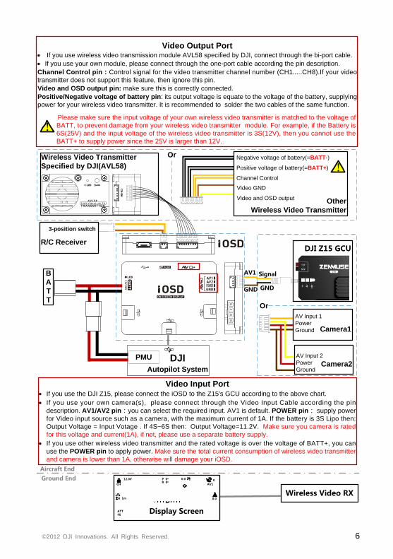
Video Input Port· If you use the DJI Z15, please connect the iOSD to the Z15's GCU according to the above chart.
· If you use your own camera(s), please connect through the Video Input Cable according the pin
description. AV1/AV2 pin:you can select the required input. AV1 is default. POWER pin: supply power
for Video input source such as a camera, with the maximum current of 1A. If the battery is 3S Lipo then:
Output Voltage = Input Votage . If 4S~6S then: Output Voltage=11.2V. Make sure you camera is rated
for this voltage and current(1A), if not, please use a separate battery supply.
· If you use other wireless video transmitter and the rated voltage is over the voltage of BATT+, you can
use the POWER pin to apply power. Make sure the total current consumption of wireless video transmitter
and camera is lower than 1A, otherwise will damage your iOSD.
Aircraft End
Ground End
R/C Receiver
3-position switch
Wireless Video Transmitter
Specified by DJI(AVL58)
Other
Wireless Video Transmitter
Negative voltage of battery(=BATT-)
Positive voltage of battery(=BATT+)
Channel Control
Video GND
Video and OSD output
Or
DJI Z15 GCU
AV Input 1
Power
Ground
AV Input 2
Power
Ground
Camera1
Camera2
Or
A V L 5 8
TRANSMITTER
Video Output Port· If you use wireless video transmission module AVL58 specified by DJI, connect through the bi-port cable.
· If you use your own module, please connect through the one-port cable according the pin description.
Channel Control pin:Control signal for the video transmitter channel number (CH1…..CH8).If your video
transmitter does not support this feature, then ignore this pin.
Video and OSD output pin: make sure this is correctly connected.
Positive/Negative voltage of battery pin: its output voltage is equate to the voltage of the battery, supplying
power for your wireless video transmitter. It is recommended to solder the two cables of the same function.
Please make sure the input voltage of your own wireless video transmitter is matched to the voltage of
BATT, to prevent damage from your wireless video transmitter module. For example, if the Battery is
6S(25V) and the input voltage of the wireless video transmitter is 3S(12V), then you cannot use the
BATT+ to supply power since the 25V is larger than 12V.
!
!
SignalAV1
GNDGND
©2012 DJI Innovations. All Rights Reserved. 7
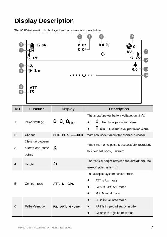
Display Description
The iOSD information is displayed on the screen as shown below.
12.0V
1m
ATTFS
0
0.0
1
3
4
107 9
D
H
P 0o
R 0o
5
6
8
13
CH AV1
m0.0 s
2 11
12
14
45~17945~179
NO Function Display Description
1 Power voltage 、 、 blink
The aircraft power battery voltage, unit in V.
:First level protection alarm
blink:Second level protection alarm
2 Channel CH1、CH2、……CH8 Wireless video transmitter channel selection.
3
Distance between
aircraft and home
points
D
When the home point is successfully recorded,
this item will show, unit in m.
4 Height H
The vertical height between the aircraft and the
take-off point, unit in m.
5 Control mode ATT、M、GPS
The autopilot system control mode.
ATT is Atti mode
GPS is GPS Atti. mode
M is Manual mode
6 Fail-safe mode FS、APT、GHome
FS is in Fail-safe mode
APT is in ground station mode
GHome is in go home status
©2012 DJI Innovations. All Rights Reserved. 8
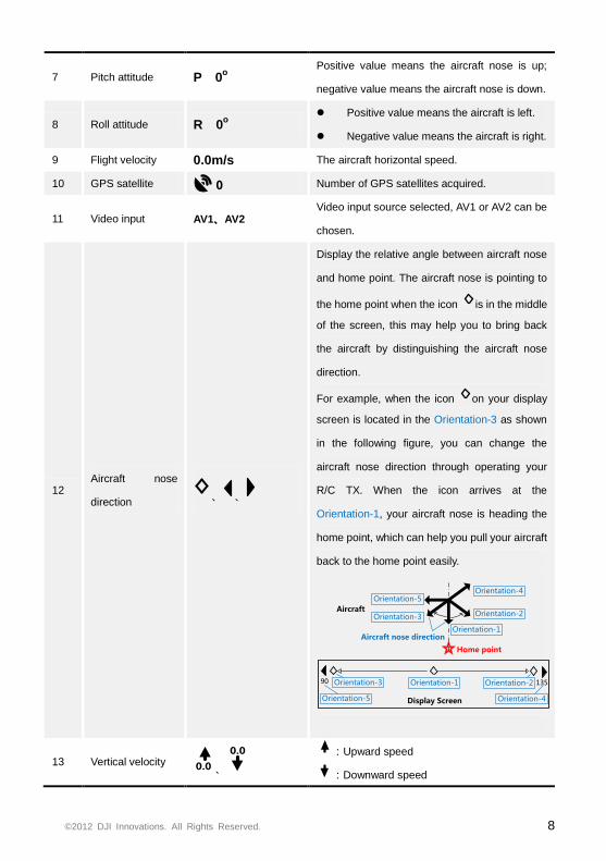
7 Pitch attitude P 0o
Positive value means the aircraft nose is up;
negative value means the aircraft nose is down.
8 Roll attitude R 0o
Positive value means the aircraft is left.
Negative value means the aircraft is right.
9 Flight velocity 0.0m/s The aircraft horizontal speed.
10 GPS satellite 0 Number of GPS satellites acquired.
11 Video input AV1、AV2 Video input source selected, AV1 or AV2 can be
chosen.
12 Aircraft nose
direction 、 、
Display the relative angle between aircraft nose
and home point. The aircraft nose is pointing to
the home point when the icon is in the middle
of the screen, this may help you to bring back
the aircraft by distinguishing the aircraft nose
direction.
For example, when the icon on your display
screen is located in the Orientation-3 as shown
in the following figure, you can change the
aircraft nose direction through operating your
R/C TX. When the icon arrives at the
Orientation-1, your aircraft nose is heading the
home point, which can help you pull your aircraft
back to the home point easily.
Home point
Orientation-4
Aircraft nose direction
90 135
Display Screen
Aircraft
Orientation-1
Orientation-2Orientation-3
Orientation-5
Orientation-1 Orientation-2Orientation-3
Orientation-4Orientation-5
13 Vertical velocity 0.0 、
0.0
:Upward speed
:Downward speed
©2012 DJI Innovations. All Rights Reserved. 9
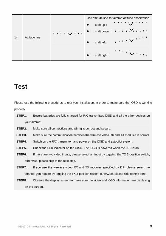
14 Attitude line
Use attitude line for aircraft attitude observation
craft up:
craft down:
craft left:
craft right:
Test
Please use the following procedures to test your installation, in order to make sure the iOSD is working
properly.
STEP1. Ensure batteries are fully charged for R/C transmitter, iOSD and all the other devices on
your aircraft.
STEP2. Make sure all connections and wiring is correct and secure.
STEP3. Make sure the communication between the wireless video RX and TX modules is normal.
STEP4. Switch on the R/C transmitter, and power on the iOSD and autopilot system.
STEP5. Check the LED indicator on the iOSD. The iOSD is powered when the LED is on.
STEP6. If there are two video inputs, please select an input by toggling the TX 3-position switch;
otherwise, please skip to the next step.
STEP7. If you use the wireless video RX and TX modules specified by DJI, please select the
channel you require by toggling the TX 3-position switch; otherwise, please skip to next step.
STEP8. Observe the display screen to make sure the video and iOSD information are displaying
on the screen.
©2012 DJI Innovations. All Rights Reserved. 10
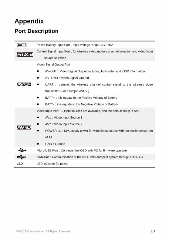
Appendix
Port Description
Power Battery Input Port,input voltage range: 11V~26V
Control Signal Input Port,for wireless video module channel selection and video input
source selection
Video Signal Output Port
AV-OUT:Video Signal Output, including both video and iOSD information
AV- GND:Video Signal Ground
UART: transmit the wireless channel control signal to the wireless video
transmitter (For example AVL58)
BATT+:it is equate to the Positive Voltage of Battery
BATT-:it is equate to the Negative Voltage of Battery
Video Input Port,2 input sources are available, and the default setup is AV1
AV1:Video Input Source 1
AV2:Video Input Source 2
POWER:11~13V, supply power for video input source with the maximum current
of 1A
GND:Ground
Micro-USB Port:Connects the iOSD with PC for firmware upgrade
CAN-Bus : Communication of the iOSD with autopilot system through CAN-Bus
LED LED indicator for power
©2012 DJI Innovations. All Rights Reserved. 11
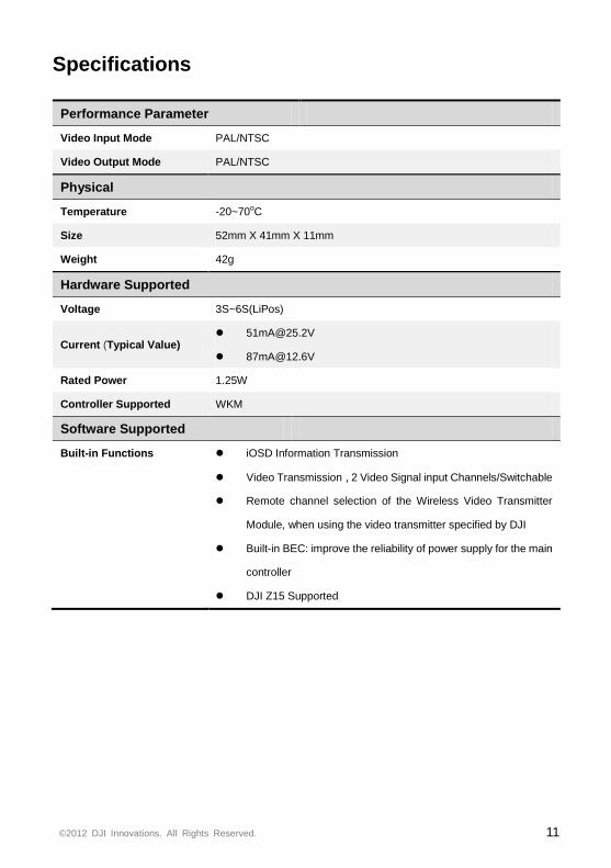
Specifications
Performance Parameter
Video Input Mode PAL/NTSC
Video Output Mode PAL/NTSC
Physical
Temperature -20~70oC
Size 52mm X 41mm X 11mm
Weight 42g
Hardware Supported
Voltage 3S~6S(LiPos)
Current (Typical Value) [email protected]
Rated Power 1.25W
Controller Supported WKM
Software Supported
Built-in Functions iOSD Information Transmission
Video Transmission,2 Video Signal input Channels/Switchable
Remote channel selection of the Wireless Video Transmitter
Module, when using the video transmitter specified by DJI
Built-in BEC: improve the reliability of power supply for the main
controller
DJI Z15 Supported
©2012 DJI Innovations. All Rights Reserved. 12
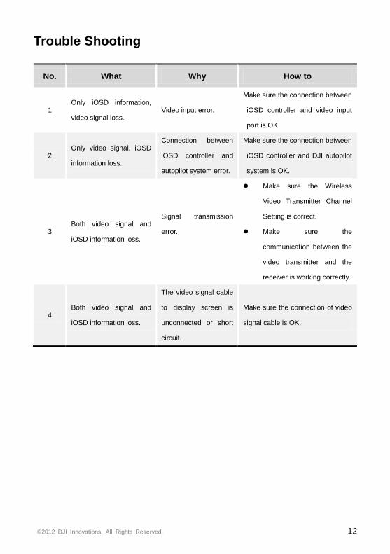
Trouble Shooting
No. What Why How to
1 Only iOSD information,
video signal loss. Video input error.
Make sure the connection between
iOSD controller and video input
port is OK.
2 Only video signal, iOSD
information loss.
Connection between
iOSD controller and
autopilot system error.
Make sure the connection between
iOSD controller and DJI autopilot
system is OK.
3 Both video signal and
iOSD information loss.
Signal transmission
error.
Make sure the Wireless
Video Transmitter Channel
Setting is correct.
Make sure the
communication between the
video transmitter and the
receiver is working correctly.
4 Both video signal and
iOSD information loss.
The video signal cable
to display screen is
unconnected or short
circuit.
Make sure the connection of video
signal cable is OK.