Embed Size (px)
Citation preview
ioPAC RTU Software User’s Manual
First Edition, October 2013
www.moxa.com/product
© 2013 Moxa Inc. All rights reserved.
ioPAC RTU Software User’s Manual
The software described in this manual is furnished under a license agreement and may be used only in accordance with the terms of that agreement.
Copyright Notice
© 2013 Moxa Inc. All rights reserved.
Trademarks
The MOXA logo is a registered trademark of Moxa Inc. All other trademarks or registered marks in this manual belong to their respective manufacturers.
Disclaimer
Information in this document is subject to change without notice and does not represent a commitment on the part of Moxa. Moxa provides this document as is, without warranty of any kind, either expressed or implied, including, but not limited to, its particular purpose. Moxa reserves the right to make improvements and/or changes to this manual, or to the products and/or the programs described in this manual, at any time. Information provided in this manual is intended to be accurate and reliable. However, Moxa assumes no responsibility for its use, or for any infringements on the rights of third parties that may result from its use. This product might include unintentional technical or typographical errors. Changes are periodically made to the information herein to correct such errors, and these changes are incorporated into new editions of the publication.
Technical Support Contact Information
www.moxa.com/support
Moxa Americas Toll-free: 1-888-669-2872 Tel: +1-714-528-6777 Fax: +1-714-528-6778
Moxa China (Shanghai office) Toll-free: 800-820-5036 Tel: +86-21-5258-9955 Fax: +86-21-5258-5505
Moxa Europe Tel: +49-89-3 70 03 99-0 Fax: +49-89-3 70 03 99-99
Moxa Asia-Pacific Tel: +886-2-8919-1230 Fax: +886-2-8919-1231
Moxa India Tel: +91-80-4172-9088 Fax: +91-80-4132-1045

Table of Contents
1. Introduction ...................................................................................................................................... 1-1 Overview ........................................................................................................................................... 1-2
Scope ........................................................................................................................................ 1-2 Related Documents ..................................................................................................................... 1-2 Supported Products ..................................................................................................................... 1-2
Software Architecture .......................................................................................................................... 1-2 Journaling Flash File System (JFFS2) ............................................................................................. 1-3 Software Package ........................................................................................................................ 1-4
2. Getting Started.................................................................................................................................. 2-1 Developing the First Program ............................................................................................................... 2-2
Hardware and Software Requirements ........................................................................................... 2-2 Development Procedure ............................................................................................................... 2-2
Configuring the Ethernet Interface ........................................................................................................ 2-2 Modifying Network Settings with the Serial Console ......................................................................... 2-2 Modifying Network Settings over the Network ................................................................................. 2-3
Connect an RTU to a Linux PC .............................................................................................................. 2-3 Install the Toolchain onto the PC .......................................................................................................... 2-4 Set Cross Compiler & glibc Environment Variables .................................................................................. 2-4 Develop Code & Compile the Program ................................................................................................... 2-4 Upload & Run the Program ................................................................................................................... 2-5
3. RTU Management .............................................................................................................................. 3-1 System Information ............................................................................................................................ 3-2 Firmware Upgrade and Default Settings ................................................................................................. 3-2
Upgrading the Firmware ............................................................................................................... 3-2 Recovering the Firmware .............................................................................................................. 3-4 Loading Factory Defaults .............................................................................................................. 3-5
Enabling and Disabling Daemons .......................................................................................................... 3-6 Run-Level Settings .............................................................................................................................. 3-7 System Time Setting ........................................................................................................................... 3-8
Setting the Time Manually ............................................................................................................ 3-8 Updating the Time with NTP Client ............................................................................................... 3-10 Updating the Time Automatically ................................................................................................. 3-10 NTP Server Setting .................................................................................................................... 3-11
Executing Scheduled Commands with Cron Daemon ............................................................................. 3-11 Software Lock .................................................................................................................................. 3-12
4. RTU Communications ........................................................................................................................ 4-1 Internet Configuration ......................................................................................................................... 4-2
Modbus TCP Master and Slave....................................................................................................... 4-2 DNS........................................................................................................................................... 4-2 Telnet/FTP .................................................................................................................................. 4-2 iptables ...................................................................................................................................... 4-3 NAT (SNAT) ................................................................................................................................ 4-7 Port Forwarding (DNAT) ............................................................................................................... 4-9 PPP Dial-up Service ..................................................................................................................... 4-9 PPPoE ...................................................................................................................................... 4-12 NFS (Network File System) Client ................................................................................................ 4-14 Sending Mail ............................................................................................................................. 4-14 OpenVPN .................................................................................................................................. 4-14 NTP Server/Client ...................................................................................................................... 4-18 Port Trunking ............................................................................................................................ 4-19
Serial Configuration .......................................................................................................................... 4-19 Modbus RTU Master ................................................................................................................... 4-19
5. RTU Data Acquisition ......................................................................................................................... 5-1 I/O Data Access.................................................................................................................................. 5-2 Battery Backup SRAM .......................................................................................................................... 5-2 Millisecond Timestamp ........................................................................................................................ 5-2 Active OPC Server............................................................................................................................... 5-2
6. RTU Programming ............................................................................................................................. 6-1 Programming Guide ............................................................................................................................ 6-2
Memory Usage ............................................................................................................................ 6-2 Using C/C++ ...................................................................................................................................... 6-2
Linux Toolchain ........................................................................................................................... 6-2 On-Line Debugging with GDB ........................................................................................................ 6-4 Library and APIs .......................................................................................................................... 6-4
A. System Commands ............................................................................................................................ A-1 Moxa Special Utilities .......................................................................................................................... A-1
1 1. Introduction
The following topics are covered in this chapter:
Overview
Scope
Related Documents
Supported Products
Software Architecture
Journaling Flash File System (JFFS2)
Software Package
ioPAC RTU Software Introduction
1-2
Overview This section introduces the scope of this document and lists related documents for reference.
Scope The purpose of this document is to help users set up and configure the ioPAC RTU and become familiar with the programming environment quickly. The following topics are covered in this document:
Introduction
Getting Started
RTU Management
RTU Communications
RTU Data Acquisition
RTU Programming
The following information is provided in the Appendix:
System Commands
Related Documents Additional information about ioPAC RTU features is available in the following manuals, which can be found in the ioPAC RTU Documentation & Software CD.
ioPAC 8500 RTU Hardware User’s Manual
C/C++ Sample Code Programming Guide for ioPAC RTU Controllers
Supported Products ioPAC 8500 Series
ioPAC 5500 Series
Software Architecture The ioPAC RTU controller uses an ARM9 based industrial grade CPU for the system and ARM Cortex™ M4 based CPUs for the modules. It provides up to 10 MB Flash ROM, 64 MB on-board SDRAM, and a microSD socket (up to 32 MB) for users to install application software and to store data directly on the controller.
The pre-installed operating system (OS) provides an open platform for software program development, which follows a standard Linux-based architecture. Software that runs on desktop PCs can be easily exported to the RTU controller with a cross compiler. Program porting can be done with the toolchain provided by Moxa.
The built-in flash ROM is partitioned into Boot Loader, Kernel, Root File System, and User directory partitions. In order to prevent user applications from crashing the Root File System, the RTU controller uses a unique Root File System with Protected Configuration for emergency use. This Root File System comes with serial and Ethernet communication capability for users to load the Factory Default Image file. User settings and applications are saved in the user directory.
To improve system reliability, the RTU controller has a built-in mechanism that prevents the system from crashing. When the kernel boots up, the RTU will mount the root file system in read-only mode, and then enable services and daemons. At the same time, the kernel will start searching for system configuration parameters via rc or inittab.
Normally, the kernel uses the Root File System to boot up the system. The Root File System is protected, and cannot be changed by users, which creates a safe zone for users.
ioPAC RTU Software Introduction
1-3
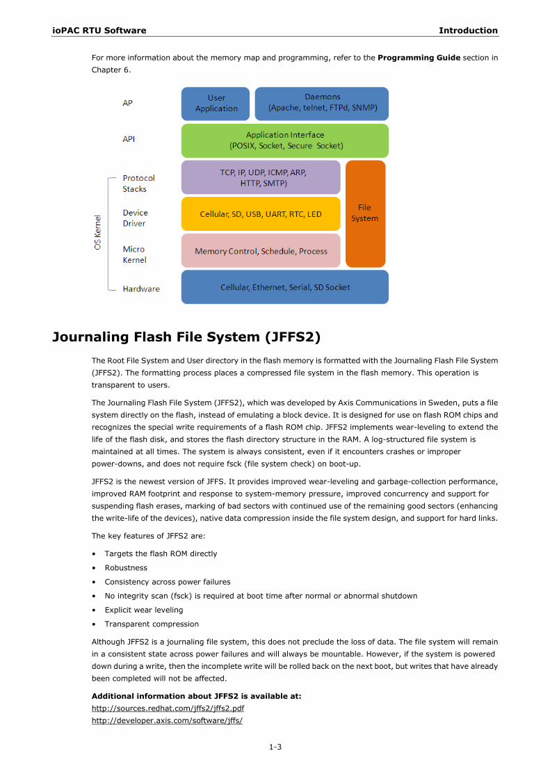
For more information about the memory map and programming, refer to the Programming Guide section in Chapter 6.
Journaling Flash File System (JFFS2) The Root File System and User directory in the flash memory is formatted with the Journaling Flash File System (JFFS2). The formatting process places a compressed file system in the flash memory. This operation is transparent to users.
The Journaling Flash File System (JFFS2), which was developed by Axis Communications in Sweden, puts a file system directly on the flash, instead of emulating a block device. It is designed for use on flash ROM chips and recognizes the special write requirements of a flash ROM chip. JFFS2 implements wear-leveling to extend the life of the flash disk, and stores the flash directory structure in the RAM. A log-structured file system is maintained at all times. The system is always consistent, even if it encounters crashes or improper power-downs, and does not require fsck (file system check) on boot-up.
JFFS2 is the newest version of JFFS. It provides improved wear-leveling and garbage-collection performance, improved RAM footprint and response to system-memory pressure, improved concurrency and support for suspending flash erases, marking of bad sectors with continued use of the remaining good sectors (enhancing the write-life of the devices), native data compression inside the file system design, and support for hard links.
The key features of JFFS2 are:
• Targets the flash ROM directly
• Robustness
• Consistency across power failures
• No integrity scan (fsck) is required at boot time after normal or abnormal shutdown
• Explicit wear leveling
• Transparent compression
Although JFFS2 is a journaling file system, this does not preclude the loss of data. The file system will remain in a consistent state across power failures and will always be mountable. However, if the system is powered down during a write, then the incomplete write will be rolled back on the next boot, but writes that have already been completed will not be affected.
Additional information about JFFS2 is available at: http://sources.redhat.com/jffs2/jffs2.pdf http://developer.axis.com/software/jffs/
ioPAC RTU Software Introduction
1-4
http://www.linux-mtd.infradead.org/
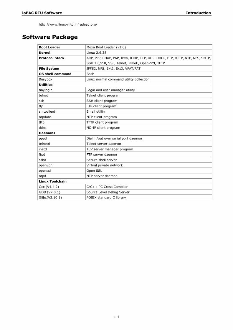
Software Package Boot Loader Moxa Boot Loader (v1.0)
Kernel Linux 2.6.38
Protocol Stack ARP, PPP, CHAP, PAP, IPv4, ICMP, TCP, UDP, DHCP, FTP, HTTP, NTP, NFS, SMTP, SSH 1.0/2.0, SSL, Telnet, PPPoE, OpenVPN, TFTP
File System JFFS2, NFS, Ext2, Ext3, VFAT/FAT
OS shell command Bash
Busybox Linux normal command utility collection
Utilities tinylogin Login and user manager utility
telnet Telnet client program
ssh SSH client program
ftp FTP client program
smtpclient Email utility
ntpdate NTP client program
tftp TFTP client program
ddns NO-IP client program
Daemons pppd Dial in/out over serial port daemon
telnetd Telnet server daemon
inetd TCP server manager program
ftpd FTP server daemon
sshd Secure shell server
openvpn Virtual private network
openssl Open SSL
ntpd NTP server daemon
Linux Toolchain Gcc (V4.4.2) C/C++ PC Cross Compiler
GDB (V7.0.1) Source Level Debug Server
Glibc(V2.10.1) POSIX standard C library

2 2. Getting Started
This chapter is intended as a quick start guide to help new users set up and configure the ioPAC RTU controller quickly, and develop a simple program to run on the ioPAC RTU controller.
The following topics are covered in this chapter:
Developing the First Program
Hardware and Software Requirements
Development Procedure
Configuring the Ethernet Interface
Modifying Network Settings with the Serial Console
Modifying Network Settings over the Network
Connect an RTU to a Linux PC
Install the Toolchain onto the PC
Set Cross Compiler & glibc Environment Variables
Develop Code & Compile the Program
Upload & Run the Program
ioPAC RTU Software Getting Started
2-2
Developing the First Program This section lists the minimum hardware and software requirements, and gives an overview of program development procedures.
Hardware and Software Requirements The following hardware items are required to complete the first program.
1 x ioPAC RTU controller
1 x 9-48VDC power supply
1 x Ethernet cable
1 x PC or Laptop with following minimum requirements
CPU: Intel Pentium 4 or above
RAM: 512 MB (1024 MB recommended)
HDD: at least 200 MB of free space
Network Interface: 10/100M Ethernet
Linux Operating System (Debian 6.0.1, Ubuntu 11.04 or Fedora Core 15 are recommended)
Development Procedure Follow the steps below to complete the first program development.
Step 1: Connect an RTU to a Linux PC
Step 2: Install the Toolchain onto the PC
Step 3: Set Cross Compiler & glibc Environment Variables
Step 4: Develop Code & Compile the Program
Step 5: Upload & Run the Program
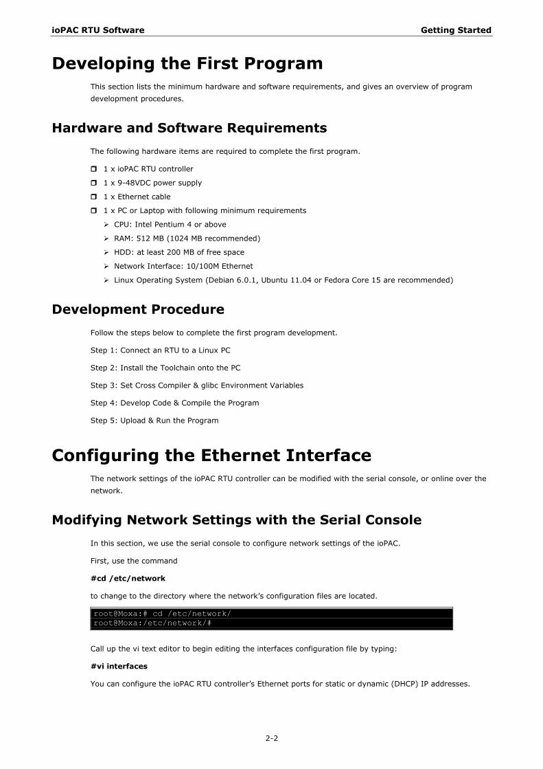
Configuring the Ethernet Interface The network settings of the ioPAC RTU controller can be modified with the serial console, or online over the network.
Modifying Network Settings with the Serial Console In this section, we use the serial console to configure network settings of the ioPAC.
First, use the command
#cd /etc/network
to change to the directory where the network’s configuration files are located. root@Moxa:# cd /etc/network/ root@Moxa:/etc/network/#
Call up the vi text editor to begin editing the interfaces configuration file by typing:
#vi interfaces
You can configure the ioPAC RTU controller’s Ethernet ports for static or dynamic (DHCP) IP addresses.
ioPAC RTU Software Getting Started
2-3
Static IP addresses:
As shown below, 2 network addresses need to be modified: address, network, netmask, and broadcast.
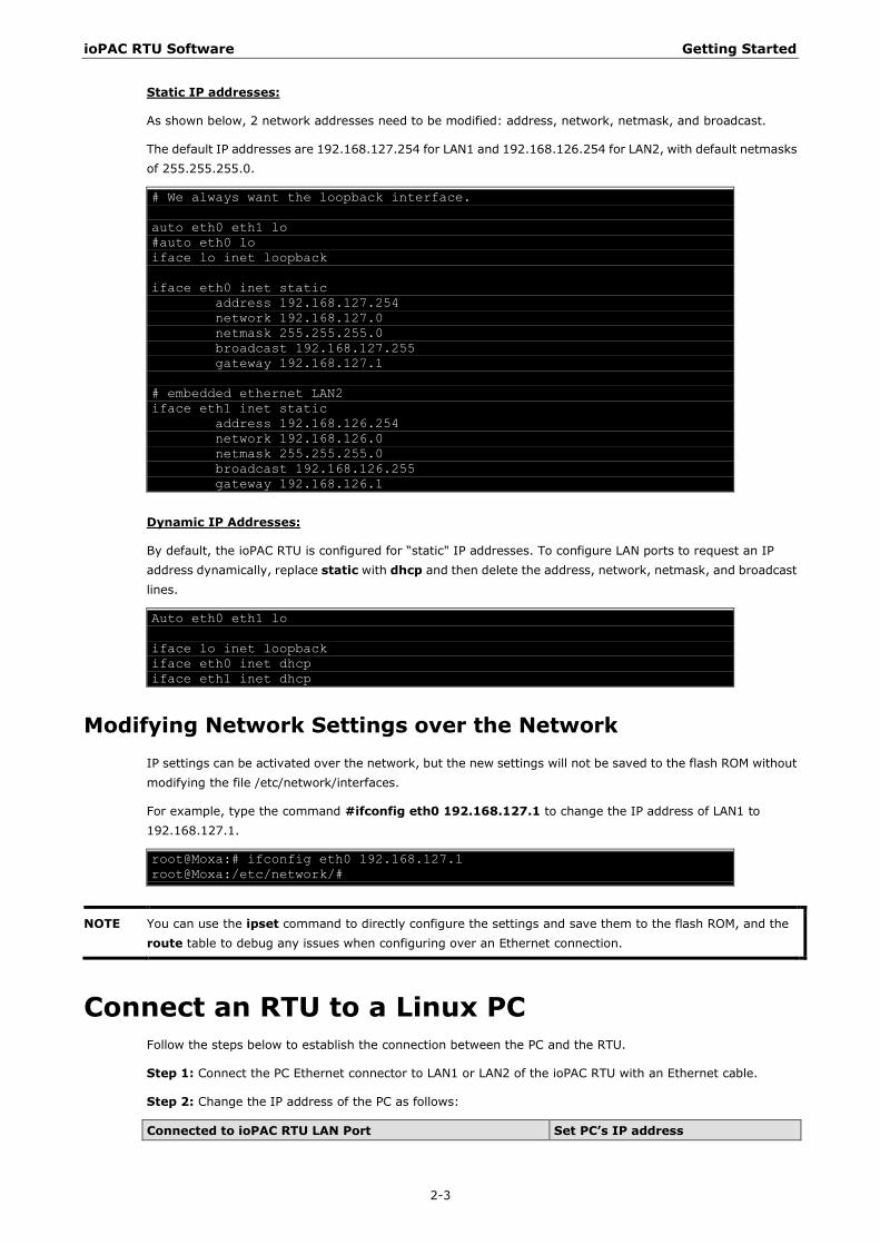
The default IP addresses are 192.168.127.254 for LAN1 and 192.168.126.254 for LAN2, with default netmasks of 255.255.255.0. # We always want the loopback interface. auto eth0 eth1 lo #auto eth0 lo iface lo inet loopback iface eth0 inet static address 192.168.127.254 network 192.168.127.0 netmask 255.255.255.0 broadcast 192.168.127.255 gateway 192.168.127.1 # embedded ethernet LAN2 iface eth1 inet static address 192.168.126.254 network 192.168.126.0 netmask 255.255.255.0 broadcast 192.168.126.255 gateway 192.168.126.1
Dynamic IP Addresses:
By default, the ioPAC RTU is configured for “static" IP addresses. To configure LAN ports to request an IP address dynamically, replace static with dhcp and then delete the address, network, netmask, and broadcast lines. Auto eth0 eth1 lo iface lo inet loopback iface eth0 inet dhcp iface eth1 inet dhcp
Modifying Network Settings over the Network IP settings can be activated over the network, but the new settings will not be saved to the flash ROM without modifying the file /etc/network/interfaces.
For example, type the command #ifconfig eth0 192.168.127.1 to change the IP address of LAN1 to 192.168.127.1. root@Moxa:# ifconfig eth0 192.168.127.1 root@Moxa:/etc/network/#
NOTE You can use the ipset command to directly configure the settings and save them to the flash ROM, and the route table to debug any issues when configuring over an Ethernet connection.
Connect an RTU to a Linux PC Follow the steps below to establish the connection between the PC and the RTU.
Step 1: Connect the PC Ethernet connector to LAN1 or LAN2 of the ioPAC RTU with an Ethernet cable.
Step 2: Change the IP address of the PC as follows:
Connected to ioPAC RTU LAN Port Set PC’s IP address
ioPAC RTU Software Getting Started
2-4
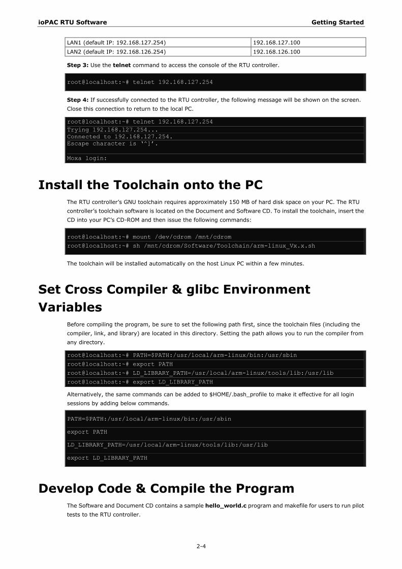
LAN1 (default IP: 192.168.127.254) 192.168.127.100
LAN2 (default IP: 192.168.126.254) 192.168.126.100
Step 3: Use the telnet command to access the console of the RTU controller.
root@localhost:~# telnet 192.168.127.254
Step 4: If successfully connected to the RTU controller, the following message will be shown on the screen. Close this connection to return to the local PC.
root@localhost:~# telnet 192.168.127.254 Trying 192.168.127.254... Connected to 192.168.127.254. Escape character is ‘^]’. Moxa login:
Install the Toolchain onto the PC The RTU controller’s GNU toolchain requires approximately 150 MB of hard disk space on your PC. The RTU controller’s toolchain software is located on the Document and Software CD. To install the toolchain, insert the CD into your PC’s CD-ROM and then issue the following commands:
root@localhost:~# mount /dev/cdrom /mnt/cdrom
root@localhost:~# sh /mnt/cdrom/Software/Toolchain/arm-linux_Vx.x.sh
The toolchain will be installed automatically on the host Linux PC within a few minutes.
Set Cross Compiler & glibc Environment Variables
Before compiling the program, be sure to set the following path first, since the toolchain files (including the compiler, link, and library) are located in this directory. Setting the path allows you to run the compiler from any directory.
root@localhost:~# PATH=$PATH:/usr/local/arm-linux/bin:/usr/sbin
root@localhost:~# export PATH
root@localhost:~# LD_LIBRARY_PATH=/usr/local/arm-linux/tools/lib:/usr/lib
root@localhost:~# export LD_LIBRARY_PATH
Alternatively, the same commands can be added to $HOME/.bash_profile to make it effective for all login sessions by adding below commands.
PATH=$PATH:/usr/local/arm-linux/bin:/usr/sbin
export PATH
LD_LIBRARY_PATH=/usr/local/arm-linux/tools/lib:/usr/lib
export LD_LIBRARY_PATH
Develop Code & Compile the Program The Software and Document CD contains a sample hello_world.c program and makefile for users to run pilot tests to the RTU controller.
ioPAC RTU Software Getting Started
2-5
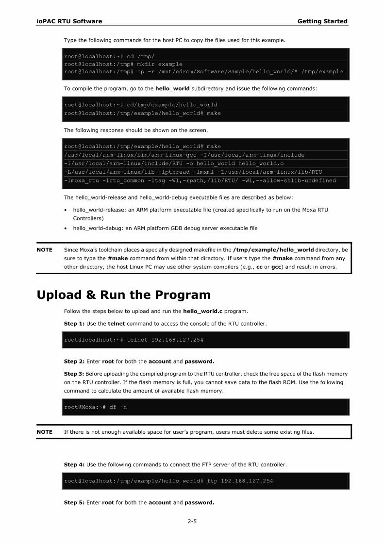
Type the following commands for the host PC to copy the files used for this example.
root@localhost:~# cd /tmp/ root@localhost:/tmp# mkdir example root@localhost:/tmp# cp –r /mnt/cdrom/Software/Sample/hello_world/* /tmp/example
To compile the program, go to the hello_world subdirectory and issue the following commands:
root@localhost:~# cd/tmp/example/hello_world
root@localhost:/tmp/example/hello_world# make
The following response should be shown on the screen.
root@localhost:/tmp/example/hello_world# make
/usr/local/arm-linux/bin/arm-linux-gcc -I/usr/local/arm-linux/include
-I/usr/local/arm-linux/include/RTU -o hello_world hello_world.o
-L/usr/local/arm-linux/lib -lpthread -lmxml -L/usr/local/arm-linux/lib/RTU
-lmoxa_rtu -lrtu_common -ltag -Wl,-rpath,/lib/RTU/ -Wl,--allow-shlib-undefined
The hello_world-release and hello_world-debug executable files are described as below:
• hello_world-release: an ARM platform executable file (created specifically to run on the Moxa RTU Controllers)
• hello_world-debug: an ARM platform GDB debug server executable file
NOTE Since Moxa’s toolchain places a specially designed makefile in the /tmp/example/hello_world directory, be sure to type the #make command from within that directory. If users type the #make command from any other directory, the host Linux PC may use other system compilers (e.g., cc or gcc) and result in errors.
Upload & Run the Program Follow the steps below to upload and run the hello_world.c program.
Step 1: Use the telnet command to access the console of the RTU controller.
root@localhost:~# telnet 192.168.127.254
Step 2: Enter root for both the account and password.
Step 3: Before uploading the compiled program to the RTU controller, check the free space of the flash memory on the RTU controller. If the flash memory is full, you cannot save data to the flash ROM. Use the following command to calculate the amount of available flash memory.
root@Moxa:~# df –h
NOTE If there is not enough available space for user’s program, users must delete some existing files.
Step 4: Use the following commands to connect the FTP server of the RTU controller.
root@localhost:/tmp/example/hello_world# ftp 192.168.127.254
Step 5: Enter root for both the account and password.
ioPAC RTU Software Getting Started
2-6
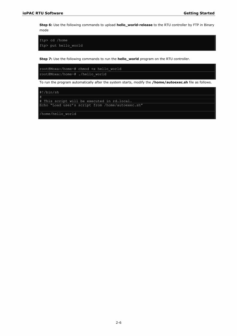
Step 6: Use the following commands to upload hello_world-release to the RTU controller by FTP in Binary mode
ftp> cd /home
ftp> put hello_world
Step 7: Use the following commands to run the hello_world program on the RTU controller.
root@Moxa:/home~# chmod +x hello_world
root@Moxa:/home~# ./hello_world
To run the program automatically after the system starts, modify the /home/autoexec.sh file as follows.
#!/bin/sh # # This script will be executed in rd.local. Echo “Load user’s script from /home/autoexec.sh” /home/hello_world

3 3. RTU Management
This chapter discusses version control, deployment, updates, and peripherals. The information in this chapter will be particularly useful when you need to run the same application on multiple ioPAC RTU controllers.
The following topics are covered in this chapter:
System Information
Firmware Upgrade and Default Settings
Upgrading the Firmware
Recovering the Firmware
Loading Factory Defaults
Enabling and Disabling Daemons
Run-Level Settings
System Time Setting
Setting the Time Manually
Updating the Time with NTP Client
Updating the Time Automatically
NTP Server Setting
Executing Scheduled Commands with Cron Daemon
Software Lock
ioPAC RTU Software RTU Management
3-2
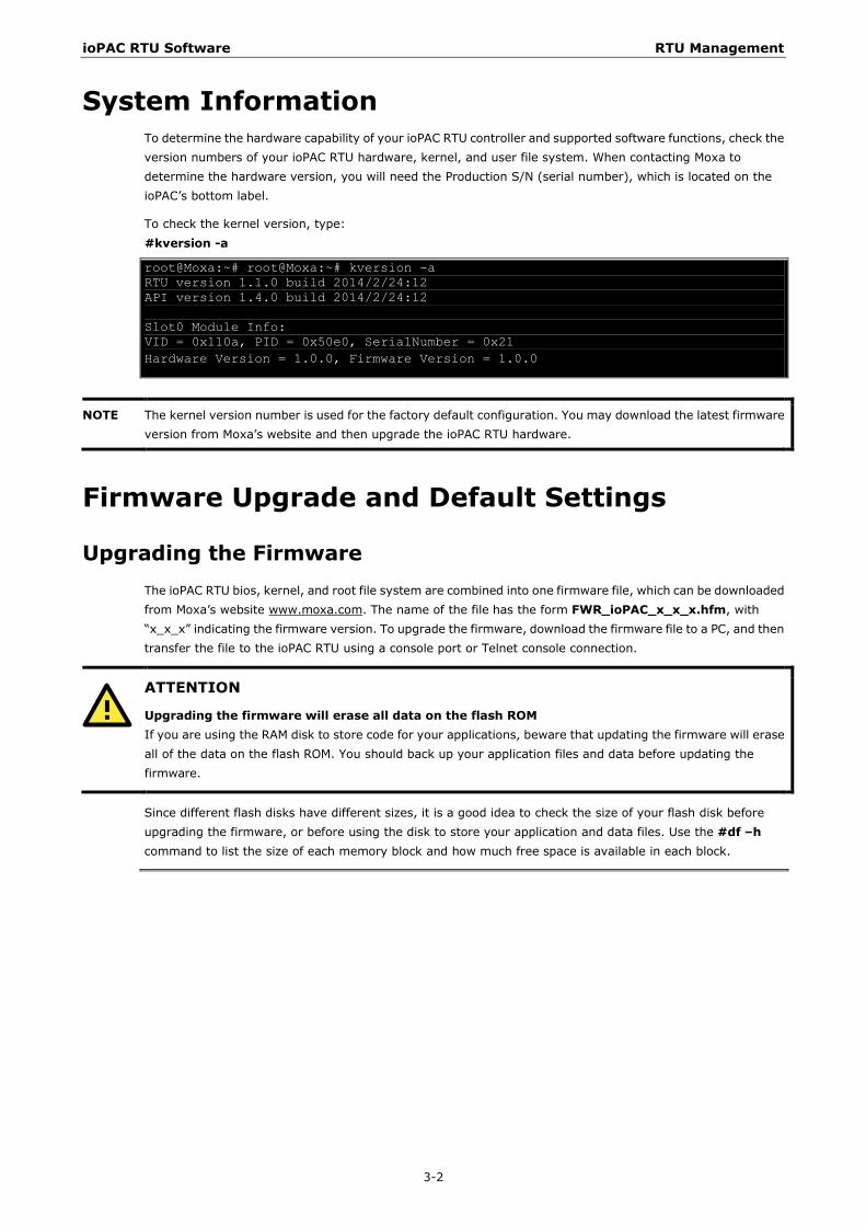
System Information To determine the hardware capability of your ioPAC RTU controller and supported software functions, check the version numbers of your ioPAC RTU hardware, kernel, and user file system. When contacting Moxa to determine the hardware version, you will need the Production S/N (serial number), which is located on the ioPAC’s bottom label.
To check the kernel version, type: #kversion -a
root@Moxa:~# root@Moxa:~# kversion -a RTU version 1.1.0 build 2014/2/24:12 API version 1.4.0 build 2014/2/24:12 Slot0 Module Info: VID = 0x110a, PID = 0x50e0, SerialNumber = 0x21 Hardware Version = 1.0.0, Firmware Version = 1.0.0
NOTE The kernel version number is used for the factory default configuration. You may download the latest firmware version from Moxa’s website and then upgrade the ioPAC RTU hardware.
Firmware Upgrade and Default Settings
Upgrading the Firmware The ioPAC RTU bios, kernel, and root file system are combined into one firmware file, which can be downloaded from Moxa’s website www.moxa.com. The name of the file has the form FWR_ioPAC_x_x_x.hfm, with “x_x_x” indicating the firmware version. To upgrade the firmware, download the firmware file to a PC, and then transfer the file to the ioPAC RTU using a console port or Telnet console connection.
ATTENTION
Upgrading the firmware will erase all data on the flash ROM If you are using the RAM disk to store code for your applications, beware that updating the firmware will erase all of the data on the flash ROM. You should back up your application files and data before updating the firmware.
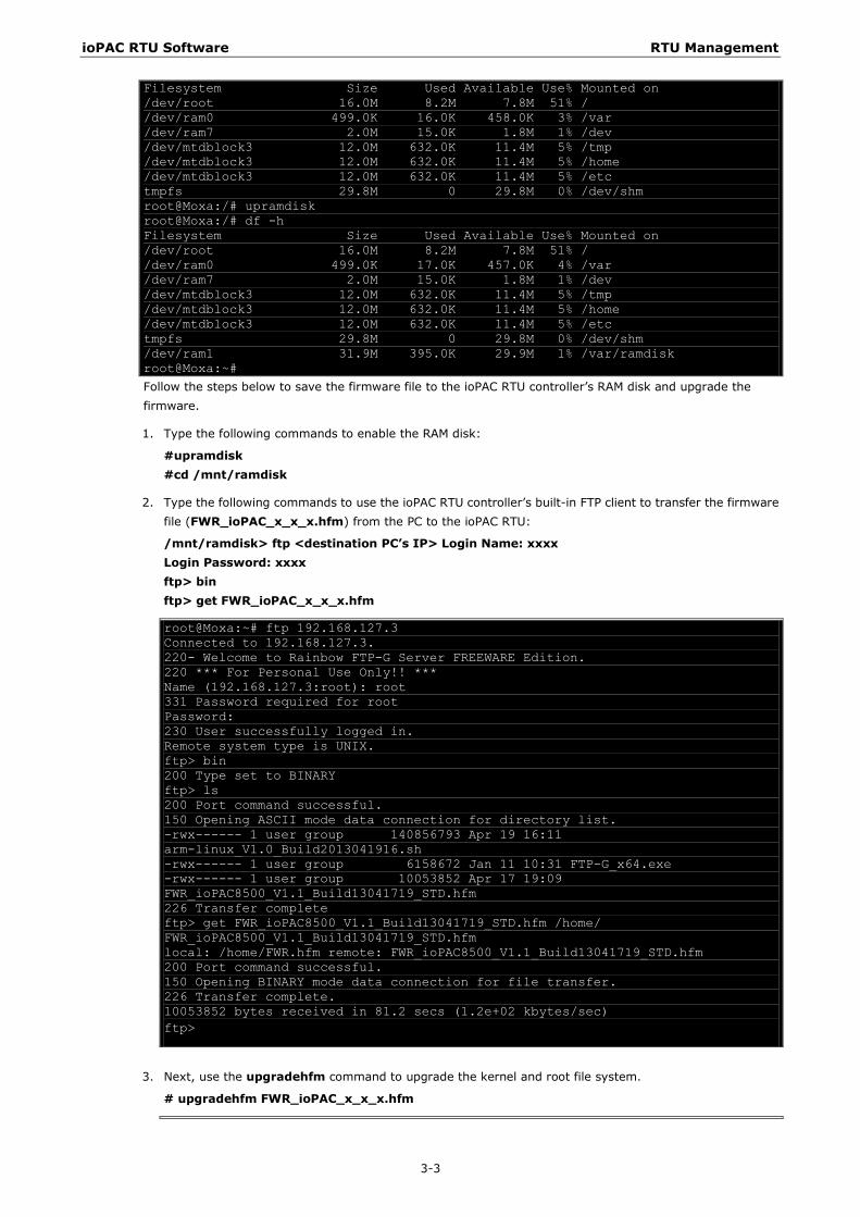
Since different flash disks have different sizes, it is a good idea to check the size of your flash disk before upgrading the firmware, or before using the disk to store your application and data files. Use the #df –h command to list the size of each memory block and how much free space is available in each block.
ioPAC RTU Software RTU Management
3-3
Filesystem Size Used Available Use% Mounted on /dev/root 16.0M 8.2M 7.8M 51% / /dev/ram0 499.0K 16.0K 458.0K 3% /var /dev/ram7 2.0M 15.0K 1.8M 1% /dev /dev/mtdblock3 12.0M 632.0K 11.4M 5% /tmp /dev/mtdblock3 12.0M 632.0K 11.4M 5% /home /dev/mtdblock3 12.0M 632.0K 11.4M 5% /etc tmpfs 29.8M 0 29.8M 0% /dev/shm root@Moxa:/# upramdisk root@Moxa:/# df -h Filesystem Size Used Available Use% Mounted on /dev/root 16.0M 8.2M 7.8M 51% / /dev/ram0 499.0K 17.0K 457.0K 4% /var /dev/ram7 2.0M 15.0K 1.8M 1% /dev /dev/mtdblock3 12.0M 632.0K 11.4M 5% /tmp /dev/mtdblock3 12.0M 632.0K 11.4M 5% /home /dev/mtdblock3 12.0M 632.0K 11.4M 5% /etc tmpfs 29.8M 0 29.8M 0% /dev/shm /dev/ram1 31.9M 395.0K 29.9M 1% /var/ramdisk root@Moxa:~# Follow the steps below to save the firmware file to the ioPAC RTU controller’s RAM disk and upgrade the firmware.
1. Type the following commands to enable the RAM disk:
#upramdisk #cd /mnt/ramdisk
2. Type the following commands to use the ioPAC RTU controller’s built-in FTP client to transfer the firmware file (FWR_ioPAC_x_x_x.hfm) from the PC to the ioPAC RTU:
/mnt/ramdisk> ftp <destination PC’s IP> Login Name: xxxx Login Password: xxxx ftp> bin ftp> get FWR_ioPAC_x_x_x.hfm
root@Moxa:~# ftp 192.168.127.3 Connected to 192.168.127.3. 220- Welcome to Rainbow FTP-G Server FREEWARE Edition. 220 *** For Personal Use Only!! *** Name (192.168.127.3:root): root 331 Password required for root Password: 230 User successfully logged in. Remote system type is UNIX. ftp> bin 200 Type set to BINARY ftp> ls 200 Port command successful. 150 Opening ASCII mode data connection for directory list. -rwx------ 1 user group 140856793 Apr 19 16:11 arm-linux_V1.0_Build2013041916.sh -rwx------ 1 user group 6158672 Jan 11 10:31 FTP-G_x64.exe -rwx------ 1 user group 10053852 Apr 17 19:09 FWR_ioPAC8500_V1.1_Build13041719_STD.hfm 226 Transfer complete ftp> get FWR_ioPAC8500_V1.1_Build13041719_STD.hfm /home/ FWR_ioPAC8500_V1.1_Build13041719_STD.hfm local: /home/FWR.hfm remote: FWR_ioPAC8500_V1.1_Build13041719_STD.hfm 200 Port command successful. 150 Opening BINARY mode data connection for file transfer. 226 Transfer complete. 10053852 bytes received in 81.2 secs (1.2e+02 kbytes/sec) ftp>
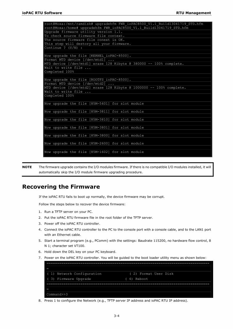
3. Next, use the upgradehfm command to upgrade the kernel and root file system.
# upgradehfm FWR_ioPAC_x_x_x.hfm
ioPAC RTU Software RTU Management
3-4
root@Moxa:/mnt/ramdisk# upgradehfm FWR_ioPAC8500_V1.1_Build13041719_STD.hfm root@Moxa:/home# upgradehfm FWR_ioPAC8500_V1.1_Build13041719_STD.hfm Upgrade firmware utility version 1.1. To check source firmware file context. The source firmware file conext is OK. This step will destory all your firmware. Continue ? (Y/N) : Now upgrade the file [KERNEL_ioPAC-8500]. Format MTD device [/dev/mtd1] ... MTD device [/dev/mtd1] erase 128 Kibyte @ 380000 -- 100% complete. Wait to write file ... Completed 100% Now upgrade the file [ROOTFS_ioPAC-8500]. Format MTD device [/dev/mtd2] ... MTD device [/dev/mtd2] erase 128 Kibyte @ 1000000 -- 100% complete. Wait to write file ... Completed 100% Now upgrade the file [85M-5401] for slot module Now upgrade the file [85M-3811] for slot module Now upgrade the file [85M-3810] for slot module Now upgrade the file [85M-3801] for slot module Now upgrade the file [85M-3800] for slot module Now upgrade the file [85M-2600] for slot module Now upgrade the file [85M-1602] for slot module
NOTE The firmware upgrade contains the I/O modules firmware. If there is no compatible I/O modules installed, it will automatically skip the I/O module firmware upgrading procedure.
Recovering the Firmware If the ioPAC RTU fails to boot up normally, the device firmware may be corrupt.
Follow the steps below to recover the device firmware:
1. Run a TFTP server on your PC.
2. Put the ioPAC RTU firmware file in the root folder of the TFTP server.
3. Power off the ioPAC RTU controller.
4. Connect the ioPAC RTU controller to the PC to the console port with a console cable, and to the LAN1 port with an Ethernet cable.
5. Start a terminal program (e.g., PComm) with the settings: Baudrate 115200, no hardware flow control, 8 N 1; character set VT100.
6. Hold down the DEL key on your PC keyboard.
7. Power on the ioPAC RTU controller. You will be guided to the boot loader utility menu as shown below:
=============================================================================
=
( 1) Network Configuration ( 2) Format User Disk
( 3) Firmware Upgrade ( 4) Reboot
=============================================================================
=
Command>>3
8. Press 1 to configure the Network (e.g., TFTP server IP address and ioPAC RTU IP address).
ioPAC RTU Software RTU Management
3-5
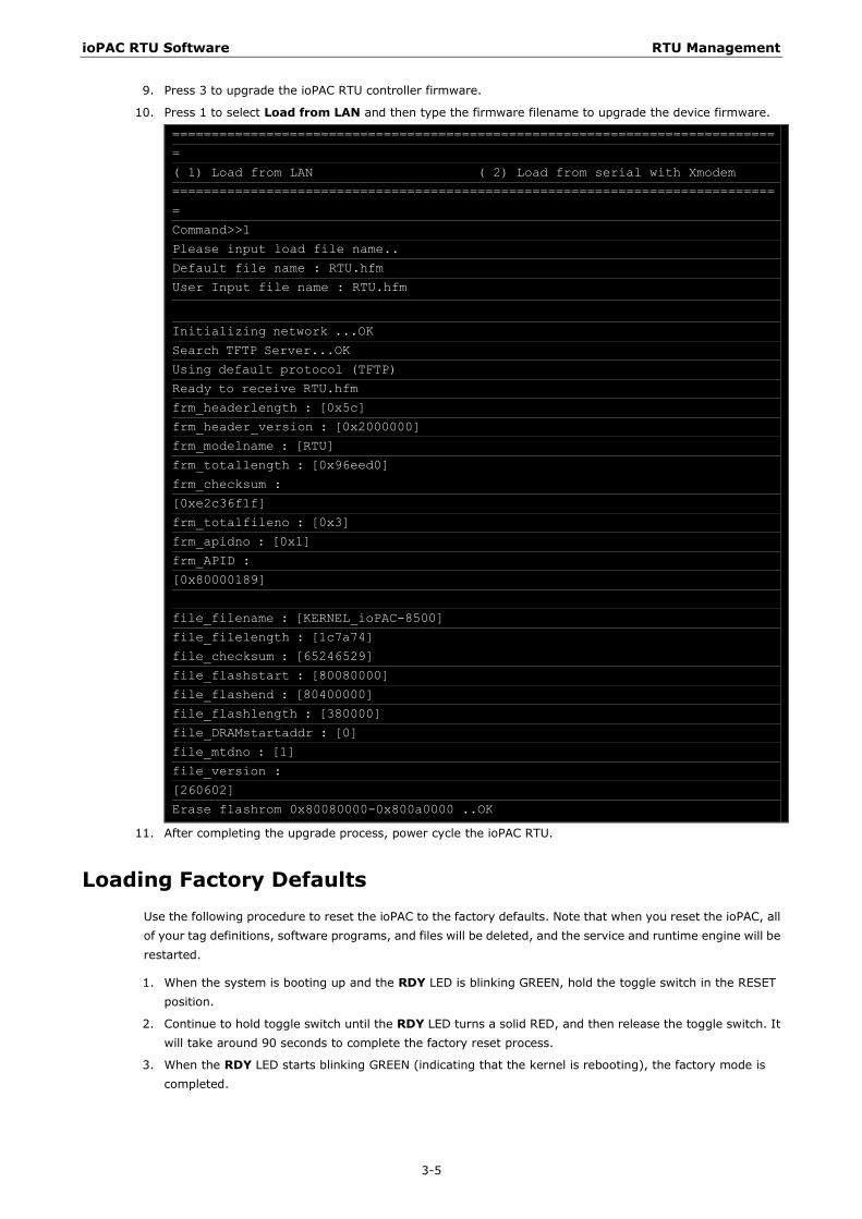
9. Press 3 to upgrade the ioPAC RTU controller firmware.
10. Press 1 to select Load from LAN and then type the firmware filename to upgrade the device firmware.
=============================================================================
=
( 1) Load from LAN ( 2) Load from serial with Xmodem
=============================================================================
=
Command>>1
Please input load file name..
Default file name : RTU.hfm
User Input file name : RTU.hfm
Initializing network ...OK
Search TFTP Server...OK
Using default protocol (TFTP)
Ready to receive RTU.hfm
frm_headerlength : [0x5c]
frm_header_version : [0x2000000]
frm_modelname : [RTU]
frm_totallength : [0x96eed0]
frm_checksum :
[0xe2c36f1f]
frm_totalfileno : [0x3]
frm_apidno : [0x1]
frm_APID :
[0x80000189]
file_filename : [KERNEL_ioPAC-8500]
file_filelength : [1c7a74]
file_checksum : [65246529]
file_flashstart : [80080000]
file_flashend : [80400000]
file_flashlength : [380000]
file_DRAMstartaddr : [0]
file_mtdno : [1]
file_version :
[260602]
Erase flashrom 0x80080000-0x800a0000 ..OK
11. After completing the upgrade process, power cycle the ioPAC RTU.
Loading Factory Defaults Use the following procedure to reset the ioPAC to the factory defaults. Note that when you reset the ioPAC, all of your tag definitions, software programs, and files will be deleted, and the service and runtime engine will be restarted.
1. When the system is booting up and the RDY LED is blinking GREEN, hold the toggle switch in the RESET position.
2. Continue to hold toggle switch until the RDY LED turns a solid RED, and then release the toggle switch. It will take around 90 seconds to complete the factory reset process.
3. When the RDY LED starts blinking GREEN (indicating that the kernel is rebooting), the factory mode is completed.
ioPAC RTU Software RTU Management
3-6
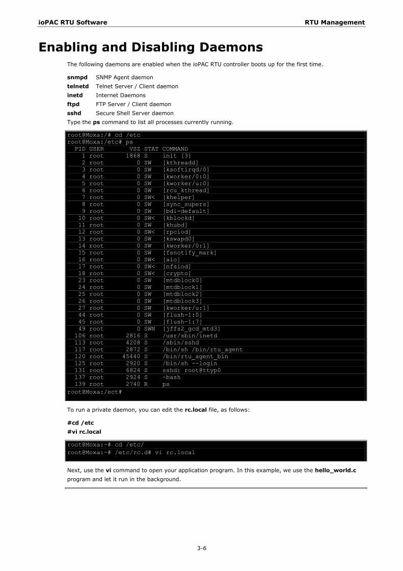
Enabling and Disabling Daemons The following daemons are enabled when the ioPAC RTU controller boots up for the first time.
snmpd SNMP Agent daemon telnetd Telnet Server / Client daemon inetd Internet Daemons ftpd FTP Server / Client daemon sshd Secure Shell Server daemon Type the ps command to list all processes currently running.
root@Moxa:/# cd /etc root@Moxa:/etc# ps PID USER VSZ STAT COMMAND 1 root 1868 S init [3] 2 root 0 SW [kthreadd] 3 root 0 SW [ksoftirqd/0] 4 root 0 SW [kworker/0:0] 5 root 0 SW [kworker/u:0] 6 root 0 SW [rcu_kthread] 7 root 0 SW< [khelper] 8 root 0 SW [sync_supers] 9 root 0 SW [bdi-default] 10 root 0 SW< [kblockd] 11 root 0 SW [khubd] 12 root 0 SW< [rpciod] 13 root 0 SW [kswapd0] 14 root 0 SW [kworker/0:1] 15 root 0 SW [fsnotify_mark] 16 root 0 SW< [aio] 17 root 0 SW< [nfsiod] 18 root 0 SW< [crypto] 23 root 0 SW [mtdblock0] 24 root 0 SW [mtdblock1] 25 root 0 SW [mtdblock2] 26 root 0 SW [mtdblock3] 27 root 0 SW [kworker/u:1] 44 root 0 SW [flush-1:0] 45 root 0 SW [flush-1:7] 49 root 0 SWN [jffs2_gcd_mtd3] 106 root 2816 S /usr/sbin/inetd 113 root 4208 S /sbin/sshd 117 root 2872 S /bin/sh /bin/rtu_agent 120 root 45440 S /bin/rtu_agent_bin 125 root 2920 S /bin/sh --login 131 root 6824 S sshd: root@ttyp0 137 root 2924 S -bash 139 root 2740 R ps root@Moxa:/ect#
To run a private daemon, you can edit the rc.local file, as follows:
#cd /etc #vi rc.local
root@Moxa:~# cd /etc/ root@Moxa:~# /etc/rc.d# vi rc.local
Next, use the vi command to open your application program. In this example, we use the hello_world.c program and let it run in the background.
ioPAC RTU Software RTU Management
3-7
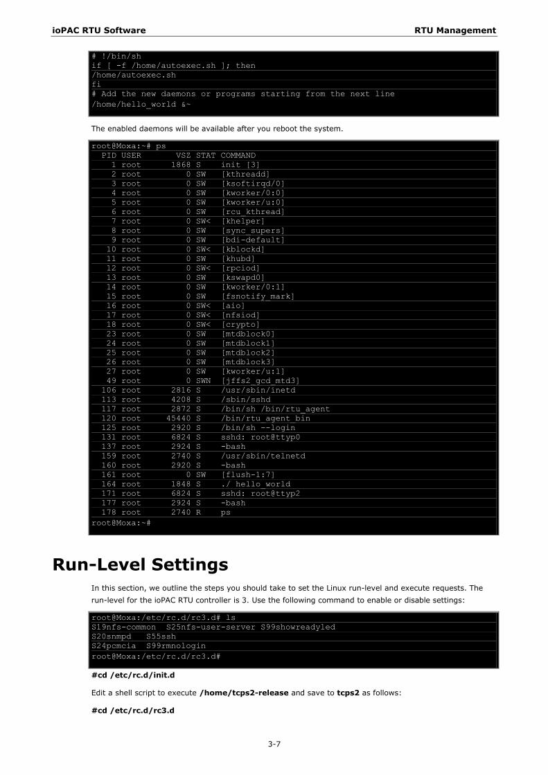
# !/bin/sh if [ -f /home/autoexec.sh ]; then /home/autoexec.sh fi # Add the new daemons or programs starting from the next line /home/hello_world &~
The enabled daemons will be available after you reboot the system.
root@Moxa:~# ps PID USER VSZ STAT COMMAND 1 root 1868 S init [3] 2 root 0 SW [kthreadd] 3 root 0 SW [ksoftirqd/0] 4 root 0 SW [kworker/0:0] 5 root 0 SW [kworker/u:0] 6 root 0 SW [rcu_kthread] 7 root 0 SW< [khelper] 8 root 0 SW [sync_supers] 9 root 0 SW [bdi-default] 10 root 0 SW< [kblockd] 11 root 0 SW [khubd] 12 root 0 SW< [rpciod] 13 root 0 SW [kswapd0] 14 root 0 SW [kworker/0:1] 15 root 0 SW [fsnotify_mark] 16 root 0 SW< [aio] 17 root 0 SW< [nfsiod] 18 root 0 SW< [crypto] 23 root 0 SW [mtdblock0] 24 root 0 SW [mtdblock1] 25 root 0 SW [mtdblock2] 26 root 0 SW [mtdblock3] 27 root 0 SW [kworker/u:1] 49 root 0 SWN [jffs2_gcd_mtd3] 106 root 2816 S /usr/sbin/inetd 113 root 4208 S /sbin/sshd 117 root 2872 S /bin/sh /bin/rtu_agent 120 root 45440 S /bin/rtu_agent_bin 125 root 2920 S /bin/sh --login 131 root 6824 S sshd: root@ttyp0 137 root 2924 S -bash 159 root 2740 S /usr/sbin/telnetd 160 root 2920 S -bash 161 root 0 SW [flush-1:7] 164 root 1848 S ./ hello_world 171 root 6824 S sshd: root@ttyp2 177 root 2924 S -bash 178 root 2740 R ps root@Moxa:~#
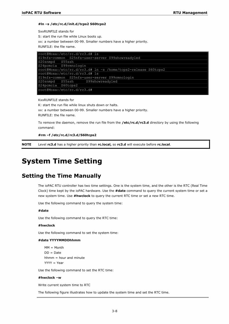
Run-Level Settings In this section, we outline the steps you should take to set the Linux run-level and execute requests. The run-level for the ioPAC RTU controller is 3. Use the following command to enable or disable settings:
root@Moxa:/etc/rc.d/rc3.d# ls S19nfs-common S25nfs-user-server S99showreadyled S20snmpd S55ssh S24pcmcia S99rmnologin root@Moxa:/etc/rc.d/rc3.d#
#cd /etc/rc.d/init.d
Edit a shell script to execute /home/tcps2-release and save to tcps2 as follows:
#cd /etc/rc.d/rc3.d
ioPAC RTU Software RTU Management
3-8
#ln –s /etc/rc.d/init.d/tcps2 S60tcps2
SxxRUNFILE stands for S: start the run file while Linux boots up. xx: a number between 00-99. Smaller numbers have a higher priority. RUNFILE: the file name.
root@Moxa:/etc/rc.d/rc3.d# ls S19nfs-common S25nfs-user-server S99showreadyled S20snmpd S55ssh S24pcmcia S99rmnologin root@Moxa:/etc/rc.d/rc3.d# ln –s /home/tcps2-release S60tcps2 root@Moxa:/etc/rc.d/rc3.d# ls S19nfs-common S25nfs-user-server S99rmnologin S20snmpd S55ssh S99showreadyled S24pcmcia S60tcps2 root@Moxa:/etc/rc.d/rc3.d#
KxxRUNFILE stands for K: start the run file while linux shuts down or halts. xx: a number between 00-99. Smaller numbers have a higher priority. RUNFILE: the file name.
To remove the daemon, remove the run file from the /etc/rc.d/rc3.d directory by using the following command:
#rm –f /etc/rc.d/rc3.d/S60tcps2
NOTE Level rc3.d has a higher priority than rc.local, so rc3.d will execute before rc.local.
System Time Setting
Setting the Time Manually The ioPAC RTU controller has two time settings. One is the system time, and the other is the RTC (Real Time Clock) time kept by the ioPAC hardware. Use the #date command to query the current system time or set a new system time. Use #hwclock to query the current RTC time or set a new RTC time.
Use the following command to query the system time:
#date
Use the following command to query the RTC time:
#hwclock
Use the following command to set the system time:
#date YYYYMMDDhhmm
MM = Month DD = Date hhmm = hour and minute YYYY = Year
Use the following command to set the RTC time:
#hwclock –w
Write current system time to RTC
The following figure illustrates how to update the system time and set the RTC time.

ioPAC RTU Software RTU Management
3-9
root@Moxa:/# date Fri May 10 02:35:39 UTC 2013 root@Moxa:/# hwclock Fri May 10 02:35:43 2013 0.000000 seconds root@Moxa:/# date 201305101037 Fri May 10 10:37:00 UTC 2013 root@Moxa:/# hwclock -w root@Moxa:/# date ; hwclock Fri May 10 10:37:32 UTC 2013 Fri May 10 10:37:32 2013 0.000000 seconds root@Moxa:/#
ioPAC RTU Software RTU Management
3-10
Updating the Time with NTP Client The ioPAC RTU controller has a built-in NTP (Network Time Protocol) client that is used to initialize a time request to a remote NTP server. Use #ntpdate <this client utility> to update the system time.
#ntpdate time.stdtime.gov.tw
#hwclock –w
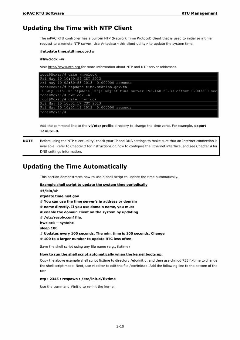
Visit http://www.ntp.org for more information about NTP and NTP server addresses.
root@Moxa:/# date ;hwclock Fri May 10 10:50:54 CST 2013 Fri May 10 02:50:53 2013 0.000000 seconds root@Moxa:/# ntpdate time.stdtion.gov.tw 10 May 10:51:03 ntpdate[156]: adjust time server 192.168.50.33 offset 0.007500 sec root@Moxa:/# hwclock -w root@Moxa:/# date; hwclock Fri May 10 10:51:17 CST 2013 Fri May 10 10:51:16 2013 0.000000 seconds root@Moxa:/#
Add the command line to the vi/etc/profile directory to change the time zone. For example, export TZ=CST-8.
NOTE Before using the NTP client utility, check your IP and DNS settings to make sure that an Internet connection is available. Refer to Chapter 2 for instructions on how to configure the Ethernet interface, and see Chapter 4 for DNS settings information.
Updating the Time Automatically This section demonstrates how to use a shell script to update the time automatically.
Example shell script to update the system time periodically
#!/bin/sh ntpdate time.nist.gov # You can use the time server’s ip address or domain # name directly. If you use domain name, you must # enable the domain client on the system by updating # /etc/resolv.conf file. hwclock –-systohc sleep 100 # Updates every 100 seconds. The min. time is 100 seconds. Change # 100 to a larger number to update RTC less often.
Save the shell script using any file name (e.g., fixtime)
How to run the shell script automatically when the kernel boots up
Copy the above example shell script fixtime to directory /etc/init.d, and then use chmod 755 fixtime to change the shell script mode. Next, use vi editor to edit the file /etc/inittab. Add the following line to the bottom of the file:
ntp : 2345 : respawn : /etc/init.d/fixtime
Use the command #init q to re-init the kernel.
ioPAC RTU Software RTU Management
3-11
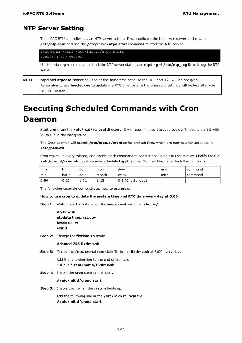
NTP Server Setting The ioPAC RTU controller has an NTP server setting. First, configure the time sync server at the path /etc/ntp.conf and use the /etc/init.d/ntpd start command to start the NTP server.
root@Moxa:/etc# /etc/init.d/ntpd start Starting ntp server
Use the ntpq -pn command to check the NTP server status, and ntpd –g –l /etc/ntp_log & to debug the NTP server.
NOTE ntpd and ntpdate cannot be used at the same time because the UDP port 123 will be occupied. Remember to use hwclock-w to update the RTC time, or else the time sync settings will be lost after you restart the device.
Executing Scheduled Commands with Cron Daemon
Start cron from the /etc/rc.d/rc.local directory. It will return immediately, so you don’t need to start it with ‘&’ to run in the background.
The Cron daemon will search /etc/cron.d/crontab for crontab files, which are named after accounts in /etc/passwd.
Cron wakes up every minute, and checks each command to see if it should be run that minute. Modify the file /etc/cron.d/crontab to set up your scheduled applications. Crontab files have the following format:
mm h dom mon dow user command
min hour date month week user command
0-59 0-23 1-31 1-12 0-6 (0 is Sunday)
The following example demonstrates how to use cron.
How to use cron to update the system time and RTC time every day at 8:00
Step 1: Write a shell script named fixtime.sh and save it to /home/.
#!/bin/sh ntpdate time.nist.gov hwclock –w exit 0
Step 2: Change the fixtime.sh mode.
#chmod 755 fixtime.sh
Step 3: Modify the /etc/cron.d/crontab file to run fixtime.sh at 8:00 every day.
Add the following line to the end of crontab: * 8 * * * root/home/fixtime.sh
Step 4: Enable the cron daemon manually.
#/etc/init.d/crond start
Step 5: Enable cron when the system boots up.
Add the following line in the /etc/rc.d/rc.local file #/etc/init.d/crond start
ioPAC RTU Software RTU Management
3-12
Software Lock Software Lock is an innovative technology developed by the Moxa engineering team. It can be adopted by a system integrator or developer to protect his/her applications from being copied. An application is compiled into a binary format bound to the ioPAC RTU and the operating system (OS) that the application runs on. So as long as the application is obtained from the development PC, it can be installed on the same hardware and the same operating system, resulting in a loss of the add-on value created by the developer.
Moxa’s engineers used data encryption to develop this protection mechanism for your applications. The binary file associated with each of your applications needs to undergo an additional encryption process after you have developed it. The process requires you to install an encryption key on the ioPAC RTU.
1. Choose an encryption key (e.g.,”ABigKey”) and install it on the ioPAC RTU controller using the pre-loaded setkey utility program.
#setkey ABigKey
NOTE: set an empty string to clear the encryption key on the ioPAC RTU controller by:
#setkey ““
2. Develop and compile your program in the development PC.
3. On the development PC, run the binencryptor utility program to encrypt your program with an encryption key.
#binencryptor yourProgram ABigKey
4. Upload the encrypted program file to the ioPAC RTU by FTP or NFS and test the program.
The encryption key is a computer-wise key. That is to say, an ioPAC RTU has only one key installed. Running the setkey program multiple times overrides the existing key.
To prove the effectiveness of this software protection mechanism, prepare an ioPAC RTU that has not been installed an encryption key or install a key different from that used to encrypt your program. In any case, the encrypted program fails immediately.
This mechanism also allows an ioPAC RTU with an encryption key to bypass programs that are not encrypted, and is useful in developing and testing programs on the ioPAC RTU.

4 4. RTU Communications
In this chapter, we explain how to configure the ioPAC RTU various communication functions.
The following topics are covered in this chapter:
Internet Configuration
Modbus TCP Master and Slave
DNS
Telnet/FTP
iptables
NAT (SNAT)
Port Forwarding (DNAT)
PPP Dial-up Service
PPPoE
NFS (Network File System) Client
Sending Mail
OpenVPN
NTP Server/Client
Port Trunking
Serial Configuration
Modbus RTU Master
ioPAC RTU Software RTU Communications
4-2
Internet Configuration
Modbus TCP Master and Slave Modbus TCP is a very common communication protocol in industrial applications and the ioPAC RTU controller has built-in Modbus TCP master and slave functions. For more detailed information, refer to the C/C++ Sample Code Programming Guide for ioPAC RTU Controllers.
DNS The ioPAC RTU controllers can be set as a DNS client but not a DNS server. To set up the ioPAC as a DNS client, edit three configuration files: /etc/hosts, /etc/resolv.conf, and /etc/nsswitch.conf.
/etc/hosts
This is the first file that the Linux system reads to resolve the host name and IP address.
/etc/resolv.conf
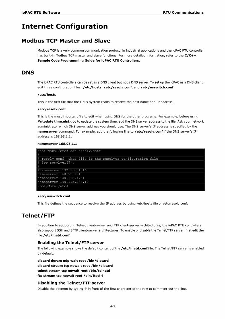
This is the most important file to edit when using DNS for the other programs. For example, before using #ntpdate time.nist.goc to update the system time, add the DNS server address to the file. Ask your network administrator which DNS server address you should use. The DNS server’s IP address is specified by the nameserver command. For example, add the following line to /etc/resolv.conf if the DNS server’s IP address is 168.95.1.1:
nameserver 168.95.1.1
root@Moxa:/etc# cat resolv.conf # # resolv.conf This file is the resolver configuration file # See resolver(5). # #nameserver 192.168.1.16 nameserver 168.95.1.1 nameserver 140.115.1.31 nameserver 140.115.236.10 root@Moxa:/etc#
/etc/nsswitch.conf
This file defines the sequence to resolve the IP address by using /etc/hosts file or /etc/resolv.conf.
Telnet/FTP In addition to supporting Telnet client-server and FTP client-server architectures, the ioPAC RTU controllers also support SSH and SFTP client-server architectures. To enable or disable the Telnet/FTP server, first edit the file /etc/inetd.conf.
Enabling the Telnet/FTP server The following example shows the default content of the /etc/inetd.conf file. The Telnet/FTP server is enabled by default:
discard dgram udp wait root /bin/discard discard stream tcp nowait root /bin/discard telnet stream tcp nowait root /bin/telnetd ftp stream tcp nowait root /bin/ftpd -l
Disabling the Telnet/FTP server Disable the daemon by typing # in front of the first character of the row to comment out the line.
ioPAC RTU Software RTU Communications
4-3
iptables The iptables command is an administrative tool for setting up, maintaining, and inspecting the Linux kernel’s IP packet filter rule tables. Several different tables are defined, with each table containing built-in chains and user-defined chains.
Each chain is a list of rules that apply to a certain type of packet. Each rule specifies what to do with a matching packet. A rule (such as a jump to a user-defined chain in the same table) is called a “target.”
The ioPAC RTU controllers support 3 types of iptables tables: Filter tables, NAT tables, and Mangle tables:
A. Filter tables—includes three chains:
INPUT chain OUTPUT chain FORWARD chain
B. NAT tables—includes three chains:
PREROUTING chain—transfers the destination IP address (DNAT) POSTROUTING chain—works after the routing process and before the Ethernet device process to transfer the source IP address (SNAT) OUTPUT chain—produces local packets
sub-tables
Source NAT (SNAT)—changes the first source packet IP address Destination NAT (DNAT)—changes the first destination packet IP address MASQUERADE—a special form for SNAT. If one host can connect to the Internet, then other computers that connect to this host can connect to the Internet when the computer does not have an actual IP address. REDIRECT—a special form of DNAT that re-sends packets to a local host independent of the destination IP address.
C. Mangle tables—includes two chains
PREROUTING chain—pre-processes packets before the routing process. OUTPUT chain—processes packets after the routing process. It has three extensions—TTL, MARK, TOS.
ioPAC RTU Software RTU Communications
4-4
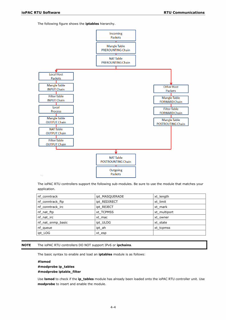
The following figure shows the iptables hierarchy.
The ioPAC RTU controllers support the following sub-modules. Be sure to use the module that matches your application.
nf_conntrack ipt_MASQUERADE xt_length
nf_conntrack_ftp ipt_REDIRECT xt_limit
nf_conntrack_irc ipt_REJECT xt_mark
nf_nat_ftp xt_TCPMSS xt_multiport
nf_nat_irc xt_mac xt_owner
nf_nat_snmp_basic ipt_ULOG xt_state
nf_queue ipt_ah xt_tcpmss
ipt_LOG xt_esp
NOTE The ioPAC RTU controllers DO NOT support IPv6 or ipchains.
The basic syntax to enable and load an iptables module is as follows:
#lsmod #modprobe ip_tables #modprobe iptable_filter
Use lsmod to check if the ip_tables module has already been loaded onto the ioPAC RTU controller unit. Use modprobe to insert and enable the module.
ioPAC RTU Software RTU Communications
4-5
Use the following command to load the modules (iptable_filter, iptable_mangle, iptable_nat): #modprobe iptable_filter
NOTE iptables plays the role of packet filter or NAT. Take care when setting up the iptables rules. If the rules are not correct, remote hosts that connect via a LAN or PPP may be denied access. We recommend using the serial console to set up the iptables. Click on the following links for more information about iptables: http://www.linuxguruz.com/iptables/ http://www.netfilter.org/documentation/HOWTO//packet-filtering-HOWTO.html
To illustrate the iptables syntax, we have divided our discussion of the various rules into three categories: observe and erase chain rules, define policy rules, and append or delete rules.
Observe and Erase Chain Rules
Usage: # iptables [-t tables] [-L] [-n]
-t tables: Table to manipulate (default: ‘filter’); example: nat or filter. -L [chain]: Lists all rules in selected chains. If no chain is selected, all chains are listed. -n: Numeric output of addresses and ports.
# iptables [-t tables] [-FXZ]
-F: Flush the selected chain (all the chains in the table if none is listed). -X: Delete the specified user-defined chain. -Z: Set the packet and byte counters in all chains to zero.
Examples: # iptables -L -n
In this example, since we do not use the -t parameter, the system uses the default ‘filter’ table. Three chains are included: INPUT, OUTPUT, and FORWARD. INPUT chains are accepted automatically, and all connections are accepted without being filtered.
#iptables –F #iptables –X #iptables –Z
ioPAC RTU Software RTU Communications
4-6
Define Policy for Chain Rules
Usage: # iptables [-t tables] [-P] [INPUT, OUTPUT, FORWARD, PREROUTING, OUTPUT, POSTROUTING] [ACCEPT, DROP]
-P: Set the policy for the chain to the given target. INPUT: For packets coming into the ioPAC RTU. OUTPUT: For locally-generated packets. FORWARD: For packets routed out through the ioPAC RTU. PREROUTING: To alter packets as soon as they come in. POSTROUTING: To alter packets as they are about to be sent out.
Examples: #iptables –P INPUT DROP #iptables –P OUTPUT ACCEPT #iptables –P FORWARD ACCEPT #iptables –t nat –P PREROUTING ACCEPT #iptables –t nat –P OUTPUT ACCEPT #iptables -t nat –P POSTROUTING ACCEPT
In this example, the policy accepts outgoing packets and denies incoming packets.
Append or Delete Rules
Usage: # iptables [-t table] [-AI] [INPUT, OUTPUT, FORWARD] [-io interface] [-p tcp, udp, icmp, all] [-s IP/network] [--sport ports] [-d IP/network] [--dport ports] –j [ACCEPT. DROP]
-A: Append one or more rules to the end of the selected chain. -I: Insert one or more rules in the selected chain as the given rule number. -i: Name of an interface via which a packet is going to be received. -o: Name of an interface via which a packet is going to be sent. -p: The protocol of the rule or of the packet to check. -s: Source address (network name, host name, network IP address, or plain IP address). --sport: Source port number. -d: Destination address. --dport: Destination port number. -j: Jump target. Specifies the target of the rules; i.e., how to handle matched packets. For example, ACCEPT the packet, DROP the packet, or LOG the packet.
Examples: Example 1: Accept all packets from lo interface. # iptables –A INPUT –i lo –j ACCEPT
Example 2: Accept TCP packets from 192.168.0.1. # iptables –A INPUT –i eth0 –p tcp –s 192.168.0.1 –j ACCEPT
Example 3: Accept TCP packets from Class C network 192.168.1.0/24. # iptables –A INPUT –i eth0 –p tcp –s 192.168.1.0/24 –j ACCEPT
Example 4: Drop TCP packets from 192.168.1.25. # iptables –A INPUT –i eth0 –p tcp –s 192.168.1.25 –j DROP
Example 5: Drop TCP packets addressed for port 21. # iptables –A INPUT –i eth0 –p tcp --dport 21 –j DROP
Example 6: Accept TCP packets from 192.168.0.24 to W341’s port 137, 138, 139 # iptables –A INPUT –i eth0 –p tcp –s 192.168.0.24 --dport 137:139 –j ACCEPT
ioPAC RTU Software RTU Communications
4-7
Example 7: Drop all packets from MAC address 01:02:03:04:05:06. # iptables –A INPUT –i eth0 –p all –m mac -–mac-source 01:02:03:04:05:06 –j DROP
NOTE In Example 7, remember to issue the command #modprobe ipt_mac first to load module ipt_mac.
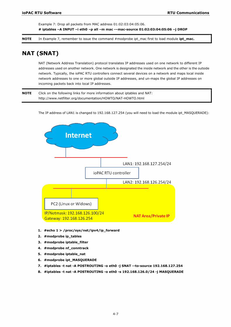
NAT (SNAT) NAT (Network Address Translation) protocol translates IP addresses used on one network to different IP addresses used on another network. One network is designated the inside network and the other is the outside network. Typically, the ioPAC RTU controllers connect several devices on a network and maps local inside network addresses to one or more global outside IP addresses, and un-maps the global IP addresses on incoming packets back into local IP addresses.
NOTE Click on the following links for more information about iptables and NAT: http://www.netfilter.org/documentation/HOWTO/NAT-HOWTO.html
The IP address of LAN1 is changed to 192.168.127.254 (you will need to load the module ipt_MASQUERADE):
1. #echo 1 > /proc/sys/net/ipv4/ip_forward
2. #modprobe ip_tables
3. #modprobe iptable_filter
4. #modprobe nf_conntrack
5. #modprobe iptable_nat
6. #modprobe ipt_MASQUERADE
7. #iptables -t nat -A POSTROUTING -o eth0 -j SNAT --to-source 192.168.127.254
8. #iptables -t nat -A POSTROUTING -o eth0 -s 192.168.126.0/24 -j MASQUERADE
ioPAC RTU Software RTU Communications
4-8
Enabling NAT at Bootup
In most real world situations, use a simple shell script to enable NAT when the ioPAC RTU controller boots up. The following script is an example.
#!/bin/bash # If you put this shell script in the /home/nat.sh # Remember to chmod 744 /home/nat.sh # Edit the rc.local file to make this shell startup automatically. # vi /etc/rc.d/rc.local # Add a line in the end of rc.local /home/nat.sh EXIF=‘eth0’ #This is an external interface for setting up a valid IP address. EXNET=‘192.168.126.0/24’ #This is an internal network address.
1. Insert modules.
# Here 2> /dev/null means the standard error messages will be dump to null device.
modprobe nf_tables 2> /dev/null
modprobe nf_conntrack 2> /dev/null
modprobe nf_conntrack_ftp 2> /dev/null
modprobe nf_conntrack_irc 2> /dev/null
modprobe iptable_nat 2> /dev/null
modprobe nf_nat_ftp 2> /dev/null
modprobe nf_nat_irc 2> /dev/null
2. Define variables, enable routing, and erase default rules.
PATH=/bin:/sbin:/usr/bin:/usr/sbin:/usr/local/bin:/usr/local/sbin
export PATH
echo “1” > /proc/sys/net/ipv4/ip_forward
/bin/iptables -F
/bin/iptables -X
/bin/iptables -Z
/bin/iptables -F -t nat
/bin/iptables -X -t nat
/bin/iptables -Z -t nat
/bin/iptables -P INPUT ACCEPT
/bin/iptables -P OUTPUT ACCEPT
/bin/iptables -P FORWARD ACCEPT
/bin/iptables -t nat -P PREROUTING ACCEPT
/bin/iptables -t nat -P POSTROUTING ACCEPT
/bin/iptables -t nat -P OUTPUT ACCEPT
3. Enable IP masquerade.
ioPAC RTU Software RTU Communications
4-9
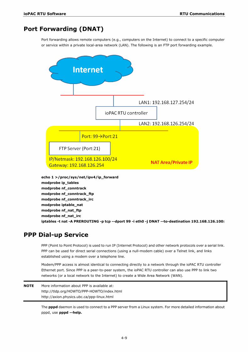
Port Forwarding (DNAT) Port forwarding allows remote computers (e.g., computers on the Internet) to connect to a specific computer or service within a private local-area network (LAN). The following is an FTP port forwarding example.
echo 1 >/proc/sys/net/ipv4/ip_forward modprobe ip_tables modprobe nf_conntrack modprobe nf_conntrack_ftp modprobe nf_conntrack_irc modprobe iptable_nat modprobe nf_nat_ftp modprobe nf_nat_irc iptables -t nat -A PREROUTING -p tcp --dport 99 -i eth0 -j DNAT --to-destination 192.168.126.100:
PPP Dial-up Service PPP (Point to Point Protocol) is used to run IP (Internet Protocol) and other network protocols over a serial link. PPP can be used for direct serial connections (using a null-modem cable) over a Telnet link, and links established using a modem over a telephone line.
Modem/PPP access is almost identical to connecting directly to a network through the ioPAC RTU controller Ethernet port. Since PPP is a peer-to-peer system, the ioPAC RTU controller can also use PPP to link two networks (or a local network to the Internet) to create a Wide Area Network (WAN).
NOTE More information about PPP is available at: http://tldp.org/HOWTO/PPP-HOWTO/index.html http://axion.physics.ubc.ca/ppp-linux.html
The pppd daemon is used to connect to a PPP server from a Linux system. For more detailed information about pppd, use pppd --help.
ioPAC RTU Software RTU Communications
4-10
Example 1: Connecting to a PPP server over a simple dial-up connection
The following command is used to connect to a PPP server by modem. Use this command for old ppp servers that prompt for a login name (replace username with the correct name) and password (replace password with the correct password). Note that debug and default route 192.1.1.17 are optional.
#pppd connect ‘chat -v “ “ ATDT5551212 CONNECT “ “ ogin: username word: password’ /dev/ttyM0 115200 debug crtscts modem defaultroute
If the PPP server does not prompt for the username and password, the command should be entered as follows. Replace username with the correct username and replace password with the correct password.
#pppd connect ‘chat -v “ “ ATDT5551212 CONNECT “ “‘user username password password /dev/ttyM0 115200 crtscts modem
The pppd options are described below:
connect ‘chat etc...’
This option gives the command to contact the PPP server. The ‘chat’ program is used to dial a remote computer. The entire command is enclosed in single quotes because pppd expects a one-word argument for the ‘connect’ option. The options for ‘chat’ are given below:
-v
verbose mode; log what we do to syslog
“ “
Double quotes—don’t wait for a prompt, but instead do ... (note that you must include a space after the second quotation mark)
ATDT5551212
Dial the modem, and then ...
CONNECT
Wait for an answer.
“ “
Send a return (null text followed by the usual return)
login: username word: password
Log in with the username and password.
/dev/
Specify the callout serial port.
115200
The baudrate.
debug
Log status in syslog.
crtscts
Use hardware flow control between computer and modem (at 115200 this is a must).
modem
Indicates that this is a modem device; pppd will hang up the phone before and after making the call.
defaultroute
ioPAC RTU Software RTU Communications
4-11
Once the PPP link is established, make it the default route; if you have a PPP link to the Internet, this is probably what you want.
192.1.1.17
This is a degenerate case of a general option of the form x.x.x.x:y.y.y.y. Here x.x.x.x is the local IP address and y.y.y.y is the IP address of the remote end of the PPP connection. If this option is not specified, or if just one side is specified, then x.x.x.x defaults to the IP address associated with the local machine’s hostname (located in /etc/hosts), and y.y.y.y is determined by the remote machine.
Example 2: Connecting to a PPP Server over a Hard-Wired Link
If a username and password are not required, use the following command (note that noipdefault is optional):
#pppd connect ‘chat –v “ “ “ “ ‘ noipdefault /dev/ttyM0 19200 crtscts “
If a username and password is required, use the following command (note that noipdefault is optional, and root is both the username and password):
#pppd connect ‘chat –v “ “ “ “ ‘ user root password root noipdefault /dev/ttyM0 19200 crtscts
How to Check the Connection
Once you’ve set up a PPP connection, there are some steps you can take to test the connection. First, type:
/sbin/ifconfig
(The folder ifconfig may be located elsewhere, depending on your distribution.) You should be able to see all the network interfaces that are UP. ppp0 should be one of them, and you should recognize the first IP address as your own, and the P-t-P address (or point-to-point address) the address of your server. Here’s what it looks like on one machine:
lo Link encap Local Loopback inet addr 127.0.0.1 Bcast 127.255.255.255 Mask 255.0.0.0 UP LOOPBACK RUNNING MTU 2000 Metric 1 RX packets 0 errors 0 dropped 0 overrun 0
ppp0 Link encap Point-to-Point Protocol inet addr 192.76.32.3 P-t-P 129.67.1.165 Mask 255.255.255.0 UP POINTOPOINT RUNNING MTU 1500 Metric 1 RX packets 33 errors 0 dropped 0 overrun 0 TX packets 42 errors 0 dropped 0 overrun 0
Now, type:
ping z.z.z.z
where z.z.z.z is the address of your name server. This should work. Here’s what the response could look like:
waddington:~$p ping 129.67.1.165 PING 129.67.1.165 (129.67.1.165): 56 data bytes 64 bytes from 129.67.1.165: icmp_seq=0 ttl=225 time=268 ms 64 bytes from 129.67.1.165: icmp_seq=1 ttl=225 time=247 ms 64 bytes from 129.67.1.165: icmp_seq=2 ttl=225 time=266 ms ^C --- 129.67.1.165 ping statistics --- 3 packets transmitted, 3 packets received, 0% packet loss round-trip min/avg/max = 247/260/268 ms waddington:~$
Try typing:
ioPAC RTU Software RTU Communications
4-12
netstat –nr
This should show three routes, something like this:
Kernel routing table Destination iface Gateway Genmask Flags Metric Ref Use 129.67.1.165 ppp0 0.0.0.0 255.255.255.255 UH 0 0 6 127.0.0.0 0.0.0.0 255.0.0.0 U 0 0 0 lo 0.0.0.0 ppp0 129.67.1.165 0.0.0.0 UG 0 0 6298
If your output looks similar but doesn’t have the destination 0.0.0.0 line (which refers to the default route used for connections), you may have run pppd without the defaultroute option. At this point you can try using Telnet, FTP, or finger, bearing in mind that you’ll have to use numeric IP addresses unless you’ve set up /etc/resolv.conf correctly.
Setting up a Machine for Incoming PPP Connections
This first example applies to using a modem, and requiring authorization with a username and password.
pppd/dev/ttyM0 115200 crtscts modem 192.168.16.1:192.168.16.2 login auth
You should also add the following line to the file /etc/ppp/pap-secrets:
* * ““ *
The first asterisk (*) lets everyone log in. The second asterisk (*) lets every host connect. The pair of double quotation marks (““) is to use the /etc/passwd file to check the password. The last asterisk (*) is to let any IP address connect.
The following example does not check the username and password:
pppd/dev/ttyM0 115200 crtscts modem 192.168.16.1:192.168.16.2
PPPoE 1. Connect the ioPAC RTU controller LAN port to an ADSL modem with a cross-over cable, hub, or switch.
2. Log in to the ioPAC RTU controller as the root user.
3. Edit the file /etc/ppp/chap-secrets and add the following:
“[email protected]”*“password”*
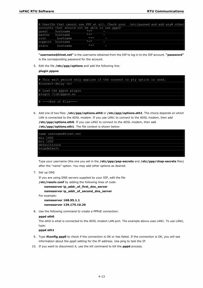
# Secrets for authentication using CHAP # client server secret IP addresses # PPPOE example, if you want to use it, you need to unmark it and modify it “[email protected]” * “password” * # following is INBOUND for everyone * * “” *
“[email protected]” is the username obtained from the ISP to log in to the ISP account. “password” is the corresponding password for the account.
4. Edit the file /etc/ppp/pap-secrets and add the following:
“[email protected]”*“password”*
# INBOUND connections # Every regular user can use PPP and has to use passwords from /etc/passwd * * “” * # PPPOE user example, if you want to use it, you need to unmark it and modify it “[email protected]” * “password” *
ioPAC RTU Software RTU Communications
4-13
# UserIDs that cannot use PPP at all. Check your /etc/passwd and add any# other accounts that should not be able to use pppd! guest hostname “*” - master hostname “*” - root hostname “*” - support hostname “*” - stats hostname “*” -
“[email protected]” is the username obtained from the ISP to log in to the ISP account. “password” is the corresponding password for the account.
5. Edit the file /etc/ppp/options and add the following line:
plugin pppoe
# This wait period only applies if the connect or pty option is used. #connect-delay <n> # Load the pppoe plugin plugin /lib/pppoe.so # ---<End of File>---
6. Add one of two files: /etc/ppp/options.eth0 or /etc/ppp/options.eth1. The choice depends on which
LAN is connected to the ADSL modem. If you use LAN1 to connect to the ADSL modem, then add /etc/ppp/options.eth0. If you use LAN2 to connect to the ADSL modem, then add /etc/ppp/options.eth1. The file context is shown below:
name [email protected] mtu 1492 mru 1492 defaultroute noipdefault ~
Type your username (the one you set in the /etc/ppp/pap-secrets and /etc/ppp/chap-secrets files) after the “name” option. You may add other options as desired.
7. Set up DNS
If you are using DNS servers supplied by your ISP, edit the file /etc/resolv.conf by adding the following lines of code:
nameserver ip_addr_of_first_dns_server nameserver ip_addr_of_second_dns_server
For example: nameserver 168.95.1.1 nameserver 139.175.10.20
8. Use the following command to create a PPPoE connection:
pppd eth0 The eth0 is what is connected to the ADSL modem LAN port. The example above uses LAN1. To use LAN2, type: pppd eth1
9. Type ifconfig ppp0 to check if the connection is OK or has failed. If the connection is OK, you will see information about the ppp0 setting for the IP address. Use ping to test the IP.
10. If you want to disconnect it, use the kill command to kill the pppd process.
ioPAC RTU Software RTU Communications
4-14
NFS (Network File System) Client The Network File System (NFS) is used to mount a disk partition on a remote machine, as if it were on a local hard drive, allowing fast, seamless sharing of files across a network. NFS allows users to develop applications for the ioPAC RTU controllers, without worrying about the amount of disk space that will be available. The ioPAC RTU controller supports NFS protocol for clients.
NOTE More information about NFS is available at: http://www.tldp.org/HOWTO/NFS-HOWTO/index.html http://nfs.sourceforge.net/nfs-howto/client.html http://nfs.sourceforge.net/nfs-howto/server.html
Setting up the ioPAC RTU Controller as an NFS Client
The following procedure is used to mount a remote NFS Server.
1. To know the NFS Server’s shared directory.
2. Establish a mount point on the NFS Client site.
3. Mount the remote directory to a local directory.
#mkdir –p /home/nfs/public #mount –t nfs NFS_Server(IP):/directory /mount/point
Example: #mount -t nfs -o nolock 192.168.13.1:/home/public /home/nfs/public
Sending Mail msmtp is a minimal SMTP client that takes an email message body and passes it on to an SMTP server. It is suitable for applications that use email to send alert messages or important logs to a specific user.
NOTE More information about smtpclient is available at: https://wiki.archlinux.org/index.php/Msmtp
To send an email message, use the ‘smtpclient’ utility, which uses SMTP protocol. Type msmtp --help to see the help message.
Example: msmtp --host=hostname --read-envelope-from [email protected]
OpenVPN OpenVPN provides two types of tunnels for users to implement VPNS: Routed IP Tunnels and Bridged Ethernet Tunnels. To begin with, check to make sure that the system has a virtual device named /dev/net/tun. If not, issue the following command:
# mknod /dev/net/tun c 10 200
An Ethernet bridge is used to connect different Ethernet networks together. The Ethernets are bundled into one bigger, “logical” Ethernet. Each Ethernet corresponds to one physical interface (or port) that is connected to the bridge.
On each OpenVPN machine, you should generate a working directory, such as /etc/openvpn, where script files and key files reside. Once established, all operations will be performed in that directory.
ioPAC RTU Software RTU Communications
4-15
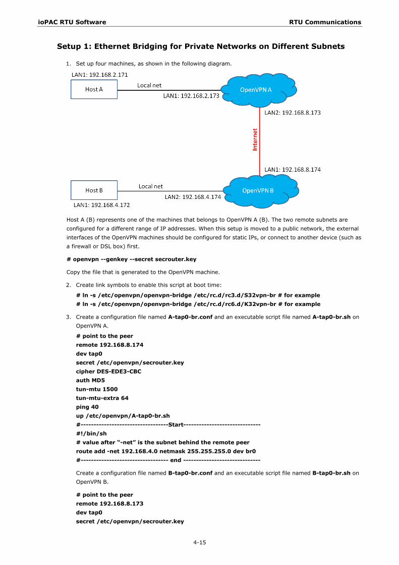
Setup 1: Ethernet Bridging for Private Networks on Different Subnets
1. Set up four machines, as shown in the following diagram.
Host A (B) represents one of the machines that belongs to OpenVPN A (B). The two remote subnets are configured for a different range of IP addresses. When this setup is moved to a public network, the external interfaces of the OpenVPN machines should be configured for static IPs, or connect to another device (such as a firewall or DSL box) first.
# openvpn --genkey --secret secrouter.key
Copy the file that is generated to the OpenVPN machine.
2. Create link symbols to enable this script at boot time:
# ln -s /etc/openvpn/openvpn-bridge /etc/rc.d/rc3.d/S32vpn-br # for example # ln -s /etc/openvpn/openvpn-bridge /etc/rc.d/rc6.d/K32vpn-br # for example
3. Create a configuration file named A-tap0-br.conf and an executable script file named A-tap0-br.sh on OpenVPN A.
# point to the peer remote 192.168.8.174 dev tap0 secret /etc/openvpn/secrouter.key cipher DES-EDE3-CBC auth MD5 tun-mtu 1500 tun-mtu-extra 64 ping 40 up /etc/openvpn/A-tap0-br.sh #----------------------------------Start------------------------------ #!/bin/sh # value after “-net” is the subnet behind the remote peer route add -net 192.168.4.0 netmask 255.255.255.0 dev br0 #---------------------------------- end ------------------------------
Create a configuration file named B-tap0-br.conf and an executable script file named B-tap0-br.sh on OpenVPN B.
# point to the peer remote 192.168.8.173 dev tap0 secret /etc/openvpn/secrouter.key
ioPAC RTU Software RTU Communications
4-16
cipher DES-EDE3-CBC auth MD5 tun-mtu 1500 tun-mtu-extra 64 ping 40 up /etc/openvpn/B-tap0-br.sh #----------------------------------Start------------------------------ #!/bin/sh # value after “-net” is the subnet behind the remote peer route add -net 192.168.2.0 netmask 255.255.255.0 dev br0 #---------------------------------- end ------------------------------
NOTE: Select cipher and authentication algorithms by specifying “cipher” and “auth”. To see which algorithms are available, type:
# openvpn --show-ciphers # openvpn --show—auths
4. Start both of OpenVPN peers,
# openvpn --config A-tap0-br.conf& # openvpn --config B-tap0-br.conf&
If you see the line “Peer Connection Initiated with 192.168.8.173:5000” on each machine, the connection between OpenVPN machines has been established successfully on UDP port 5000.
5. On each OpenVPN machine, check the routing table by typing the command:
# route
Destination Gateway Genmsk Flags Metric Ref Use Iface 192.168.4.0 * 255.255.255.0 U 0 0 0 br0
192.168.2.0 * 255.255.255.0 U 0 0 0 br0
192.168.8.0 * 255.255.255.0 U 0 0 0 eth0
Interface eth1 is connected to the bridging interface br0, to which device tap0 also connects, whereas the virtual device tun sits on top of tap0. This ensures that all traffic from internal networks connected to interface eth1 that come to this bridge write to the TAP/TUN device that the OpenVPN program monitors. Once the OpenVPN program detects traffic on the virtual device, it sends the traffic to its peer.
6. To create an indirect connection to Host B from Host A, you need to add the following routing item:
route add –net 192.168.4.0 netmask 255.255.255.0 dev eth0
To create an indirect connection to Host A from Host B, you need to add the following routing item: route add –net 192.168.2.0 netmask 255.255.255.0 dev eth0
Now ping Host B from Host A by typing: ping 192.168.4.174
A successful ping indicates that you have created a VPN system that only allows authorized users from one internal network to access users at the remote site. For this system, all data is transmitted by UDP packets on port 5000 between OpenVPN peers.
7. To shut down OpenVPN programs, type the command:
# killall -TERM openvpn
Setup 2: Ethernet Bridging for Private Networks on the Same Subnet
1. Set up four machines as shown in the following diagram:
ioPAC RTU Software RTU Communications
4-17
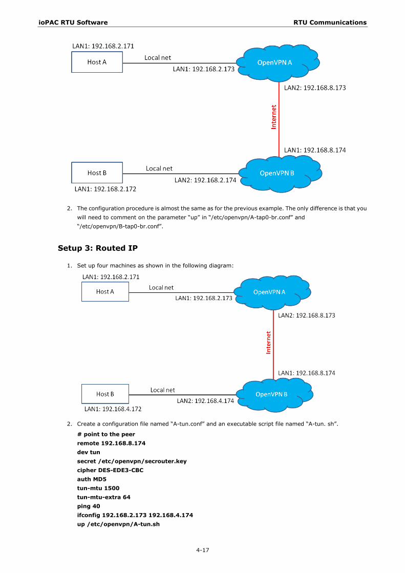
2. The configuration procedure is almost the same as for the previous example. The only difference is that you will need to comment on the parameter “up” in “/etc/openvpn/A-tap0-br.conf” and “/etc/openvpn/B-tap0-br.conf”.
Setup 3: Routed IP
1. Set up four machines as shown in the following diagram:
2. Create a configuration file named “A-tun.conf” and an executable script file named “A-tun. sh”.
# point to the peer remote 192.168.8.174 dev tun secret /etc/openvpn/secrouter.key cipher DES-EDE3-CBC auth MD5 tun-mtu 1500 tun-mtu-extra 64 ping 40 ifconfig 192.168.2.173 192.168.4.174 up /etc/openvpn/A-tun.sh
ioPAC RTU Software RTU Communications
4-18
#----------------------------------Start------------------------------ #!/bin/sh # value after “-net” is the subnet behind the remote peer route add -net 192.168.4.0 netmask 255.255.255.0 gw $5 #---------------------------------- end ------------------------------
Create a configuration file named B-tun.conf and an executable script file named B-tun.sh on OpenVPN B:
remote 192.168.8.173 dev tun secret /etc/openvpn/secrouter.key cipher DES-EDE3-CBC auth MD5 tun-mtu 1500 tun-mtu-extra 64 ping 40 ifconfig 192.168.4.174 192.168.2.173 up /etc/openvpn/B-tun.sh
#----------------------------------Start------------------------------ #!/bin/sh # value after “-net” is the subnet behind the remote peer route add -net 192.168.2.0 netmask 255.255.255.0 gw $5 #---------------------------------- end ------------------------------
Note that the parameter “ifconfig” defines the first argument as the local internal interface and the second argument as the internal interface at the remote peer.
Note that $5 is the argument that the OpenVPN program passes to the script file. Its value is the second argument of ifconfig in the configuration file.
3. Check the routing table after you run the OpenVPN programs, by typing the command:
# route
Destination Gateway Genmsk Flags Metric Ref Use Iface 192.168.4.174 * 255.255.255.255 UH 0 0 0 tun0
192.168.4.0 192.168.4.174 255.255.255.0 UG 0 0 0 tun0
192.168.2.0 * 255.255.255.0 U 0 0 0 eth1
192.168.8.0 * 255.255.255.0 U 0 0 0 eth0
NTP Server/Client Refer to the System Time Setting section in Chapter 3 for more information.
ioPAC RTU Software RTU Communications
4-19
Port Trunking To enable the port trunking function, use the debug port as described in the following steps.
1. Enable the port trunking function (IP_Bonding mode 1)
/etc/init.d/networking stop
ipset bond0 -aup -i192.168.19.151 -n255.255.255.0 -g192.168.19.254
modprobe bonding mode=1 miimon=100 use_carrier=0
/etc/init.d/networking start
2. After configuration, the virtual IP address will be set to 192.168.19.151
3. Disable the port trunking function
/etc/init.d/networking stop
ipset bond0 -adown
/etc/init.d/networking start
4. Use the ifconfig command to check the Ethernet configuration.
Serial Configuration
Modbus RTU Master Modbus RTU is a very common communication protocol in industrial applications and the ioPAC RTU controller has a built-in Modbus RTU master function. For more detailed information, see the C/C++ Sample Code Programming Guide for ioPAC RTU Controllers.

5 5. RTU Data Acquisition
This chapter explains how to use the ioPAC RTU controller for data acquisition.
The following topics are covered in this chapter:
I/O Data Access
Battery Backup SRAM
Millisecond Timestamp
Active OPC Server
ioPAC RTU Software RTU Data Acquisition
5-2
I/O Data Access ioPAC RTU controllers support many kinds of I/O modules that collect physical data from sensors. For ioPAC 8500 series, users can use modularized 85M series I/O modules.
Moxa provides C/C++ programming tools for users to develop their own project for data acquisition. C/C++ library and APIs can be found under C/C++ Sample Code Programming Guide for ioPAC RTU Controllers Files io, io_event, and misc.
One important function of the current analog input module is the Burn Out function. Users can use the MX_RTU_Module_AI_Burnout_Value_Set API to configure the Burn Out mode. If a module is burned out or a wire is disconnected, the LED will turn RED.
Battery Backup SRAM ioPAC RTU controllers support battery backup SRAM which is an important part of applications that require any kind of data backup in the event of a power failure. The size is 128 KB and users can use the APIs MX_RTU_SRAM_Read and MX_RTU_SRAM_Write to access the SRAM. For more detailed information and examples, please refer to C/C++ Sample Code Programming Guide for ioPAC RTU Controllers Files misc.
Millisecond Timestamp A timestamp is a sequence of characters or encoded information identifying when a certain event occurred, usually expressing the date and time of day and sometimes accurate to a small fraction of a second. The ioPAC 85M-1602-T and 85M-3801/11-T support modules have a dual CPU architecture, which means each I/O module has its own CPU that can easily record events in milliseconds. Using this function enables the ioPAC to collect data more accurately by providing millisecond timestamps for event and historical data analysis. Thanks to the millisecond timestamp function, operators can distinguish the sequence of data and know how to handle this event accordingly.
Users can use the APIs MX_RTU_Module_DI_Value_Get, MX_RTU_Module_AI_Raw_Value_Get, and MX_RTU_Module_AI_Eng_Value_Get to retrieve the timestamp information from I/O modules. For more detailed information and examples, please refer to C/C++ Sample Code Programming Guide for ioPAC RTU Controllers Files.
Active OPC Server Active OPC (AOPC) Server is a software package provided by Moxa that operates as an OPC driver for an HMI or SCADA system. It offers seamless connection from Moxa's ioLogik series products to SCADA systems. Active OPC Server meets the latest standard of OPC DA 3.0, which allows connections to various kinds of devices and host OPC machines.
Moxa has pioneered the concept of “active type” OPC software in the automation industry. The patented Active OPC Server offers non-polling architecture alongside the standard OPC protocol, giving users the alternative of active, push-based communication from Moxa’s RTUs and remote I/O devices. This adaptation of “push” technology means that I/O status will be updated at the Active OPC Server only when there is an I/O status change, a pre-configured interval is reached, or when a request is issued by a user. This application of push technology cuts metadata overhead, resulting in faster I/O response times and more accurate data collection than traditional pull-based architectures. With Moxa’s “active technology” advantage, users can now instantly receive alarms and real-time updates allowing for timely risk response.
Use the AOPC APIs to configure and access the AOPC tag information. For more detailed information and examples, please refer to C/C++ Sample Code Programming Guide for ioPAC RTU Controllers Files aopc.

6 6. RTU Programming
This chapter describes how to install a toolchain onto the host computer that you use to develop your applications. Cross-platform development and debugging are also discussed.
The following topics are covered in this chapter:
Programming Guide
Memory Usage
Using C/C++
Linux Toolchain
On-Line Debugging with GDB
Library and APIs
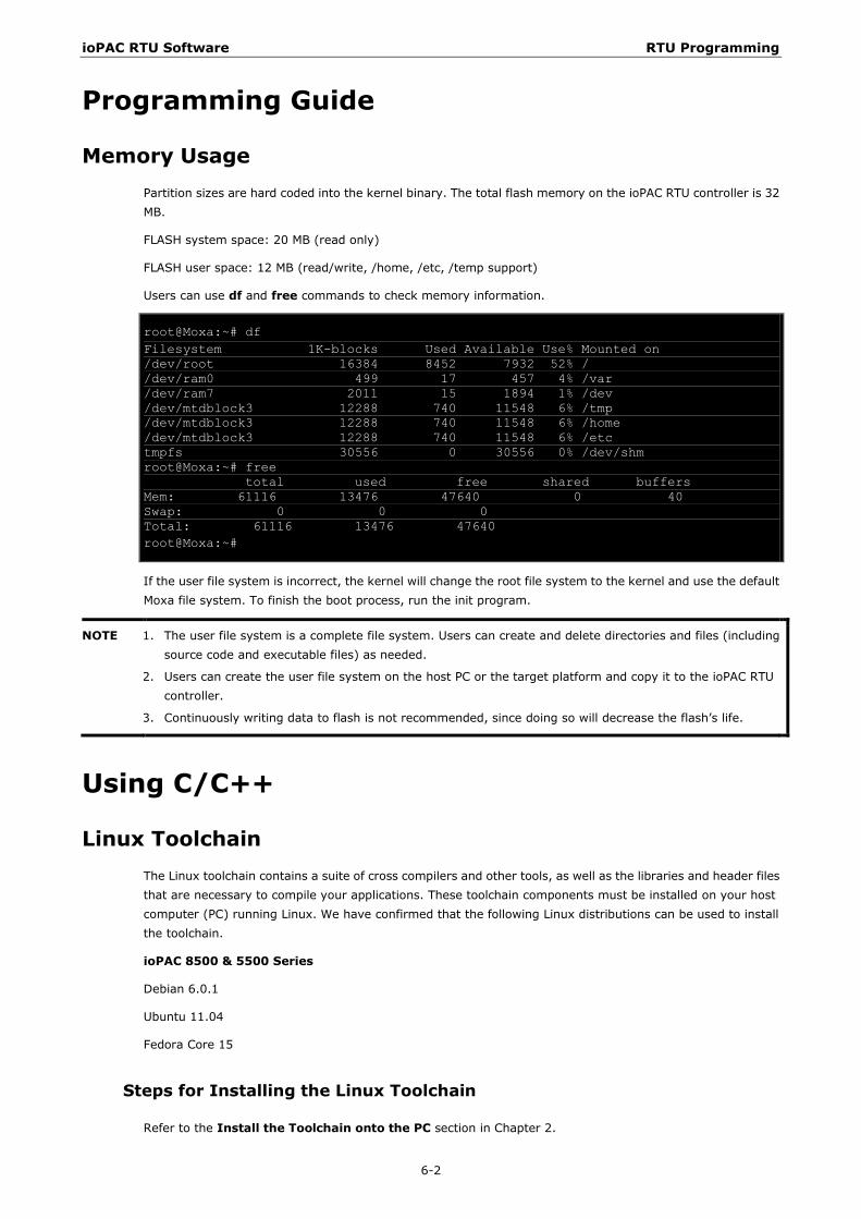
ioPAC RTU Software RTU Programming
6-2
Programming Guide
Memory Usage Partition sizes are hard coded into the kernel binary. The total flash memory on the ioPAC RTU controller is 32 MB.
FLASH system space: 20 MB (read only)
FLASH user space: 12 MB (read/write, /home, /etc, /temp support)
Users can use df and free commands to check memory information.
root@Moxa:~# df Filesystem 1K-blocks Used Available Use% Mounted on /dev/root 16384 8452 7932 52% / /dev/ram0 499 17 457 4% /var /dev/ram7 2011 15 1894 1% /dev /dev/mtdblock3 12288 740 11548 6% /tmp /dev/mtdblock3 12288 740 11548 6% /home /dev/mtdblock3 12288 740 11548 6% /etc tmpfs 30556 0 30556 0% /dev/shm root@Moxa:~# free total used free shared buffers Mem: 61116 13476 47640 0 40 Swap: 0 0 0 Total: 61116 13476 47640 root@Moxa:~#
If the user file system is incorrect, the kernel will change the root file system to the kernel and use the default Moxa file system. To finish the boot process, run the init program.
NOTE 1. The user file system is a complete file system. Users can create and delete directories and files (including source code and executable files) as needed.
2. Users can create the user file system on the host PC or the target platform and copy it to the ioPAC RTU controller.
3. Continuously writing data to flash is not recommended, since doing so will decrease the flash’s life.
Using C/C++
Linux Toolchain The Linux toolchain contains a suite of cross compilers and other tools, as well as the libraries and header files that are necessary to compile your applications. These toolchain components must be installed on your host computer (PC) running Linux. We have confirmed that the following Linux distributions can be used to install the toolchain.
ioPAC 8500 & 5500 Series
Debian 6.0.1
Ubuntu 11.04
Fedora Core 15
Steps for Installing the Linux Toolchain
Refer to the Install the Toolchain onto the PC section in Chapter 2.
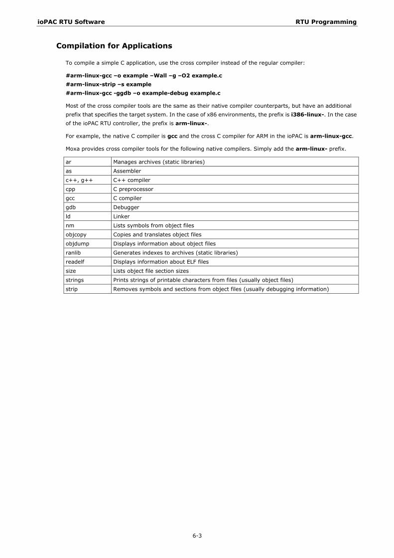
ioPAC RTU Software RTU Programming
6-3
Compilation for Applications
To compile a simple C application, use the cross compiler instead of the regular compiler:
#arm-linux-gcc –o example –Wall –g –O2 example.c #arm-linux-strip –s example #arm-linux-gcc -ggdb –o example-debug example.c
Most of the cross compiler tools are the same as their native compiler counterparts, but have an additional prefix that specifies the target system. In the case of x86 environments, the prefix is i386-linux-. In the case of the ioPAC RTU controller, the prefix is arm-linux-.
For example, the native C compiler is gcc and the cross C compiler for ARM in the ioPAC is arm-linux-gcc.
Moxa provides cross compiler tools for the following native compilers. Simply add the arm-linux- prefix.
ar Manages archives (static libraries)
as Assembler
c++, g++ C++ compiler
cpp C preprocessor
gcc C compiler
gdb Debugger
ld Linker
nm Lists symbols from object files
objcopy Copies and translates object files
objdump Displays information about object files
ranlib Generates indexes to archives (static libraries)
readelf Displays information about ELF files
size Lists object file section sizes
strings Prints strings of printable characters from files (usually object files)
strip Removes symbols and sections from object files (usually debugging information)
ioPAC RTU Software RTU Programming
6-4
On-Line Debugging with GDB The toolchain also provides an online debugging mechanism to help you develop your program. Before performing a debugging session, add the option -ggdb to compile the program. A debugging session runs on a client-server architecture on which the server gdbserver is installed on the ioPAC RTU and the client ddd is installed in the host computer. We’ll assume that you have uploaded a program named hello_world-debug to the ioPAC RTU and start to debug the program.
1. Log on to the ioPAC and run the debugging server program.
#gdbserver 192.168.127.254:2000 hello_world-debug
Process hello_world-debug created; pid=38
The debugging server listens for connections at network port 2000 from the network interface 192.168.127.254. The name of the program to be debugged follows these parameters. For a program requiring arguments, add the arguments behind the program name.
2. In the host computer, change the directory to where the program source resides.
cd /my_work_directory/myfilesystem/testprograms
3. Execute the client program.
#ddd --debugger arm-linux-gdb hello_world-debug &
4. Enter the following command at the GDB, DDD command prompt.
Target remote 192.168.127.5:2000
The command produces a line of output on the target console, similar to the following.
Remote debugging using 192.168.127.5:2000
192.168.127.5 is the host PC’s IP address, and 2000 is the port number. You can now begin debugging in the host environment using the interface provided by DDD.
5. Set an execution breakpoint by double-clicking, or by entering b main on the command line.
6. Click the cont button.
Library and APIs For more detailed information about the library and APIs, please refer to the C/C++ Sample Code Programming Guide for ioPAC RTU Controllers.
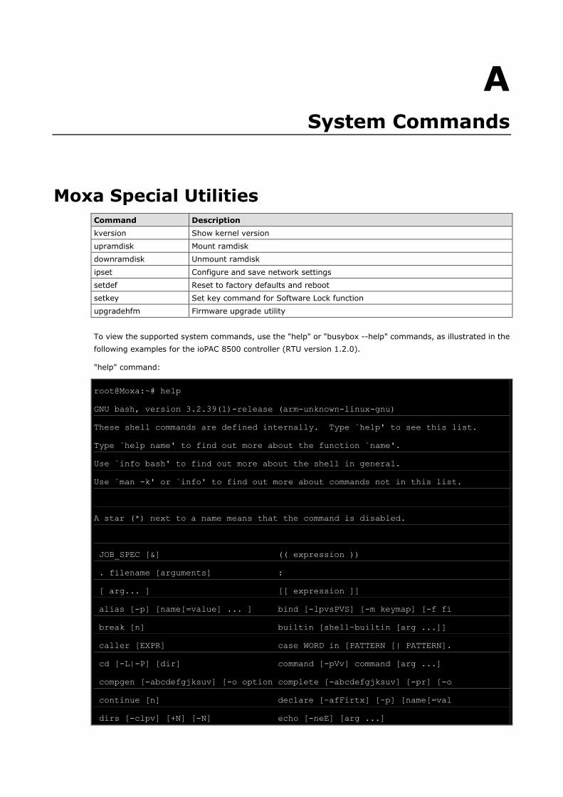
A A. System Commands
Moxa Special Utilities Command Description kversion Show kernel version
upramdisk Mount ramdisk
downramdisk Unmount ramdisk
ipset Configure and save network settings
setdef Reset to factory defaults and reboot
setkey Set key command for Software Lock function
upgradehfm Firmware upgrade utility
To view the supported system commands, use the "help" or "busybox --help" commands, as illustrated in the following examples for the ioPAC 8500 controller (RTU version 1.2.0).
"help" command:
root@Moxa:~# help
GNU bash, version 3.2.39(1)-release (arm-unknown-linux-gnu)
These shell commands are defined internally. Type `help' to see this list.
Type `help name' to find out more about the function `name'.
Use `info bash' to find out more about the shell in general.
Use `man -k' or `info' to find out more about commands not in this list.
A star (*) next to a name means that the command is disabled.
JOB_SPEC [&] (( expression ))
. filename [arguments] :
[ arg... ] [[ expression ]]
alias [-p] [name[=value] ... ] bind [-lpvsPVS] [-m keymap] [-f fi
break [n] builtin [shell-builtin [arg ...]]
caller [EXPR] case WORD in [PATTERN [| PATTERN].
cd [-L|-P] [dir] command [-pVv] command [arg ...]
compgen [-abcdefgjksuv] [-o option complete [-abcdefgjksuv] [-pr] [-o
continue [n] declare [-afFirtx] [-p] [name[=val
dirs [-clpv] [+N] [-N] echo [-neE] [arg ...]
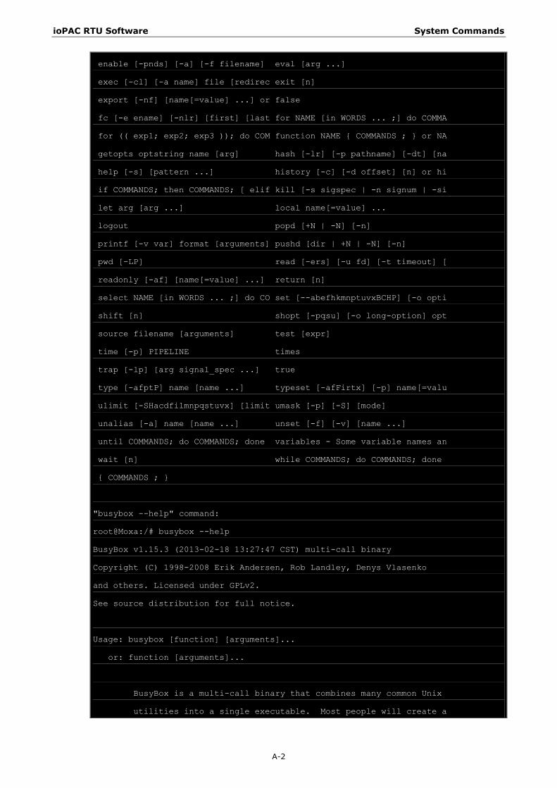
ioPAC RTU Software System Commands
A-2
enable [-pnds] [-a] [-f filename] eval [arg ...]
exec [-cl] [-a name] file [redirec exit [n]
export [-nf] [name[=value] ...] or false
fc [-e ename] [-nlr] [first] [last for NAME [in WORDS ... ;] do COMMA
for (( exp1; exp2; exp3 )); do COM function NAME { COMMANDS ; } or NA
getopts optstring name [arg] hash [-lr] [-p pathname] [-dt] [na
help [-s] [pattern ...] history [-c] [-d offset] [n] or hi
if COMMANDS; then COMMANDS; [ elif kill [-s sigspec | -n signum | -si
let arg [arg ...] local name[=value] ...
logout popd [+N | -N] [-n]
printf [-v var] format [arguments] pushd [dir | +N | -N] [-n]
pwd [-LP] read [-ers] [-u fd] [-t timeout] [
readonly [-af] [name[=value] ...] return [n]
select NAME [in WORDS ... ;] do CO set [--abefhkmnptuvxBCHP] [-o opti
shift [n] shopt [-pqsu] [-o long-option] opt
source filename [arguments] test [expr]
time [-p] PIPELINE times
trap [-lp] [arg signal_spec ...] true
type [-afptP] name [name ...] typeset [-afFirtx] [-p] name[=valu
ulimit [-SHacdfilmnpqstuvx] [limit umask [-p] [-S] [mode]
unalias [-a] name [name ...] unset [-f] [-v] [name ...]
until COMMANDS; do COMMANDS; done variables - Some variable names an
wait [n] while COMMANDS; do COMMANDS; done
{ COMMANDS ; }
"busybox --help" command:
root@Moxa:/# busybox --help
BusyBox v1.15.3 (2013-02-18 13:27:47 CST) multi-call binary
Copyright (C) 1998-2008 Erik Andersen, Rob Landley, Denys Vlasenko
and others. Licensed under GPLv2.
See source distribution for full notice.
Usage: busybox [function] [arguments]...
or: function [arguments]...
BusyBox is a multi-call binary that combines many common Unix
utilities into a single executable. Most people will create a

ioPAC RTU Software System Commands
A-3
link to busybox for each function they wish to use and BusyBox
will act like whatever it was invoked as!
Currently defined functions:
[, [[, addgroup, adduser, arp, awk, basename, brctl, bunzip2, bzcat,
bzip2, cat, chat, chgrp, chmod, chown, chroot, clear, cp, crond,
crontab, cut, date, delgroup, deluser, depmod, df, dirname, dmesg,
dnsdomainname, du, echo, egrep, env, expr, false, fdisk, fgrep, find,
flash_eraseall, free, freeramdisk, getty, grep, gunzip, gzip, halt,
head, hostname, hwclock, id, ifconfig, ifdown, ifenslave, ifup, inetd,
insmod, ip, kill, killall, killall5, klogd, ln, login, ls, lsmod,
md5sum, mdev, mkdir, mkfifo, mknod, mktemp, modprobe, more, mount, mv,
netstat, nice, passwd, pidof, ping, poweroff, ps, pwd, reboot, renice,
rm, rmdir, rmmod, route, run-parts, sed, sleep, start-stop-daemon,
stty, su, sulogin, sync, syslogd, tail, tar, tcpsvd, telnet, telnetd,
test, tftp, top, touch, traceroute, true, udhcpc, umount, uname, vi,
which, xargs, zcat
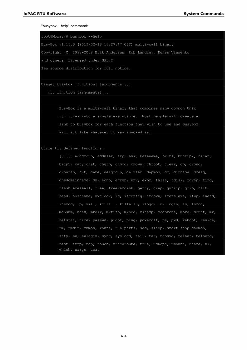
ioPAC RTU Software System Commands
A-4
"busybox --help" command:
root@Moxa:/# busybox --help
BusyBox v1.15.3 (2013-02-18 13:27:47 CST) multi-call binary
Copyright (C) 1998-2008 Erik Andersen, Rob Landley, Denys Vlasenko
and others. Licensed under GPLv2.
See source distribution for full notice.
Usage: busybox [function] [arguments]...
or: function [arguments]...
BusyBox is a multi-call binary that combines many common Unix
utilities into a single executable. Most people will create a
link to busybox for each function they wish to use and BusyBox
will act like whatever it was invoked as!
Currently defined functions:
[, [[, addgroup, adduser, arp, awk, basename, brctl, bunzip2, bzcat,
bzip2, cat, chat, chgrp, chmod, chown, chroot, clear, cp, crond,
crontab, cut, date, delgroup, deluser, depmod, df, dirname, dmesg,
dnsdomainname, du, echo, egrep, env, expr, false, fdisk, fgrep, find,
flash_eraseall, free, freeramdisk, getty, grep, gunzip, gzip, halt,
head, hostname, hwclock, id, ifconfig, ifdown, ifenslave, ifup, inetd,
insmod, ip, kill, killall, killall5, klogd, ln, login, ls, lsmod,
md5sum, mdev, mkdir, mkfifo, mknod, mktemp, modprobe, more, mount, mv,
netstat, nice, passwd, pidof, ping, poweroff, ps, pwd, reboot, renice,
rm, rmdir, rmmod, route, run-parts, sed, sleep, start-stop-daemon,
stty, su, sulogin, sync, syslogd, tail, tar, tcpsvd, telnet, telnetd,
test, tftp, top, touch, traceroute, true, udhcpc, umount, uname, vi,
which, xargs, zcat