Embed Size (px)
Citation preview
© COPYRIGHT 2007—HYTROL CONVEYOR CO., INC. BULLETIN NO. 586
IOP SOLUTIONSMANUAL
HYTROL CONVEYOR CO., INC.
Contents
Page 2
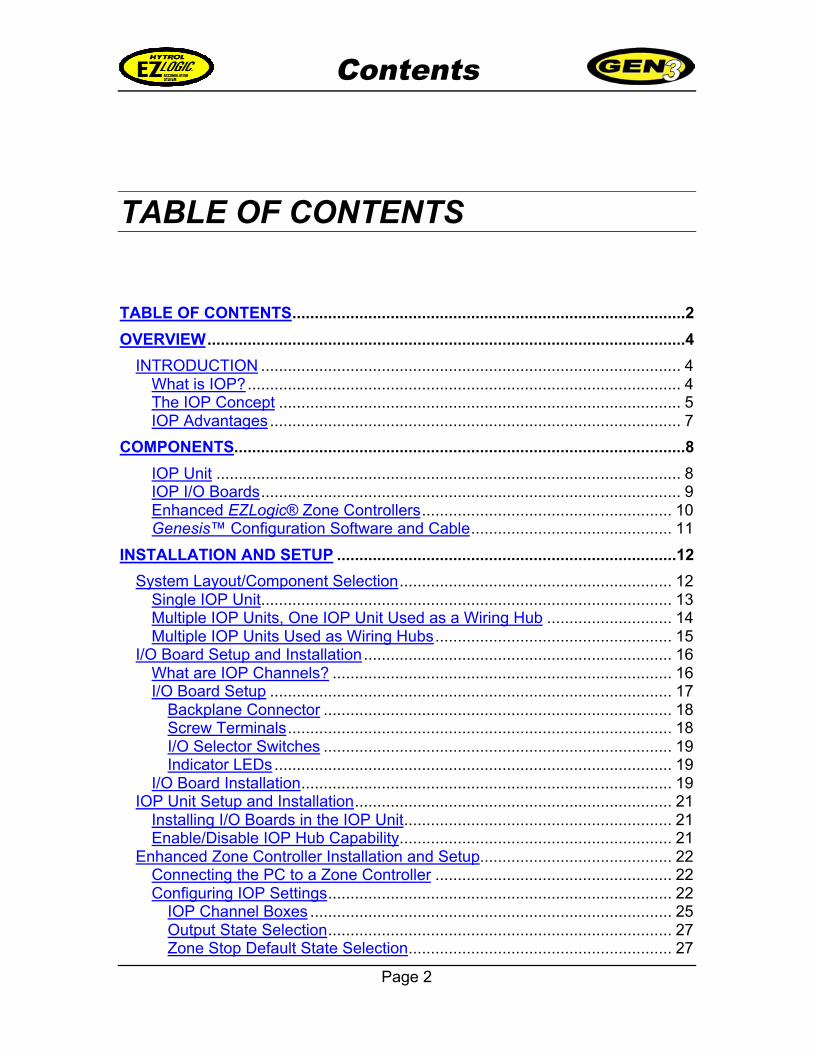
TABLE OF CONTENTS
TABLE OF CONTENTS........................................................................................2
OVERVIEW...........................................................................................................4
INTRODUCTION .............................................................................................. 4What is IOP?................................................................................................. 4The IOP Concept .......................................................................................... 5IOP Advantages............................................................................................ 7
COMPONENTS.....................................................................................................8
IOP Unit ........................................................................................................ 8IOP I/O Boards.............................................................................................. 9Enhanced EZLogic® Zone Controllers........................................................ 10Genesis™ Configuration Software and Cable............................................. 11
INSTALLATION AND SETUP ............................................................................12
System Layout/Component Selection............................................................. 12Single IOP Unit............................................................................................ 13Multiple IOP Units, One IOP Unit Used as a Wiring Hub ............................ 14Multiple IOP Units Used as Wiring Hubs..................................................... 15
I/O Board Setup and Installation..................................................................... 16What are IOP Channels? ............................................................................ 16I/O Board Setup .......................................................................................... 17
Backplane Connector .............................................................................. 18Screw Terminals...................................................................................... 18I/O Selector Switches .............................................................................. 19Indicator LEDs......................................................................................... 19
I/O Board Installation................................................................................... 19IOP Unit Setup and Installation....................................................................... 21
Installing I/O Boards in the IOP Unit............................................................ 21Enable/Disable IOP Hub Capability............................................................. 21
Enhanced Zone Controller Installation and Setup........................................... 22Connecting the PC to a Zone Controller ..................................................... 22Configuring IOP Settings............................................................................. 22
IOP Channel Boxes ................................................................................. 25Output State Selection............................................................................. 27Zone Stop Default State Selection........................................................... 27
Contents
Page 3
To Configure an Enhanced Zone Controller:............................................... 28Notes on IOP System Configuration ............................................................... 29
IOP SYSTEM OPERATION ................................................................................30
IOP Channels ................................................................................................. 30Using the IOP System for “Peer-to-Peer” Communications............................ 34
IOP COMMUNICATIONS SYSTEM SPECIFICATIONS.....................................36
I/O Board..................................................................................................... 36General.................................................................................................... 36Inputs....................................................................................................... 36Outputs.................................................................................................... 36
IOP Unit (IOP Communications Information ONLY).................................... 36General.................................................................................................... 36
Enhanced Zone Controller (IOP Information ONLY) ................................... 37Available Inputs ....................................................................................... 37Available Outputs .................................................................................... 37Output States........................................................................................... 37
Overview
Page 4
Overview
INTRODUCTIONThis manual describes how to install, configure, and use Hytrol’s EZLogic® Gen3IOP technology to simplify controls interfacing on conveyors using the EZLogic®Gen3 accumulation system. This manual is a supplement to the “EZLogic® Gen3Component Manual.” Please read both manuals carefully to familiarize yourselfwith the system and its operation.
What is IOP?“IOP” stands for “Input/Output/Power.” The IOP system gives the integratorand/or installer one central location to wire all “real time” inputs and outputs tothe EZLogic® Gen3 system. “Real time” inputs and outputs are signals betweenEZLogic® and other control devices that must be received as soon as they aresent. These include:
• Zone stop inputs
• Slug mode inputs
• Photo-eye outputs
• Other “real time” I/O
Overview
Page 5
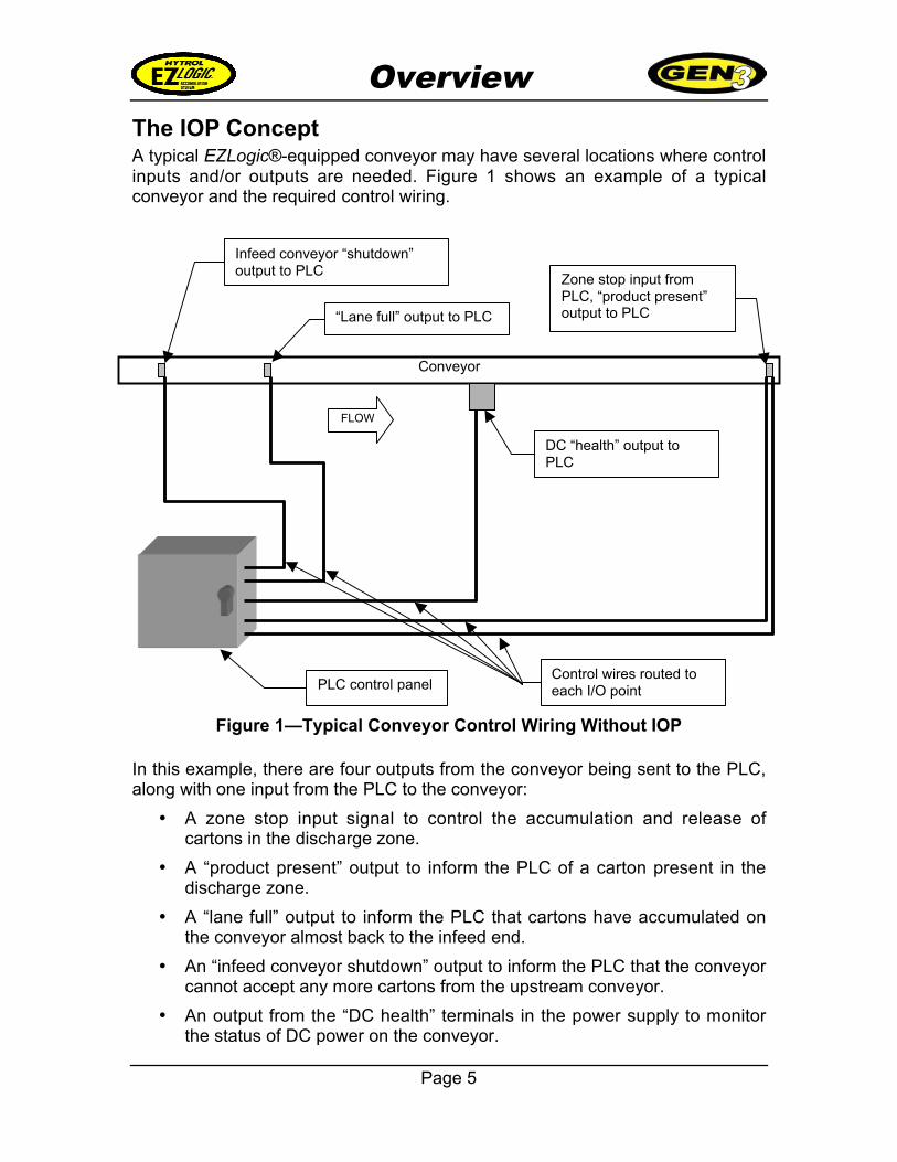
The IOP ConceptA typical EZLogic®-equipped conveyor may have several locations where controlinputs and/or outputs are needed. Figure 1 shows an example of a typicalconveyor and the required control wiring.
In this example, there are four outputs from the conveyor being sent to the PLC,along with one input from the PLC to the conveyor:
• A zone stop input signal to control the accumulation and release ofcartons in the discharge zone.
• A “product present” output to inform the PLC of a carton present in thedischarge zone.
• A “lane full” output to inform the PLC that cartons have accumulated onthe conveyor almost back to the infeed end.
• An “infeed conveyor shutdown” output to inform the PLC that the conveyorcannot accept any more cartons from the upstream conveyor.
• An output from the “DC health” terminals in the power supply to monitorthe status of DC power on the conveyor.
Figure 1—Typical Conveyor Control Wiring Without IOP
Conveyor
FLOW
Infeed conveyor “shutdown”output to PLC
“Lane full” output to PLC
DC “health” output toPLC
Zone stop input fromPLC, “product present”output to PLC
PLC control panelControl wires routed toeach I/O point
Overview
Page 6
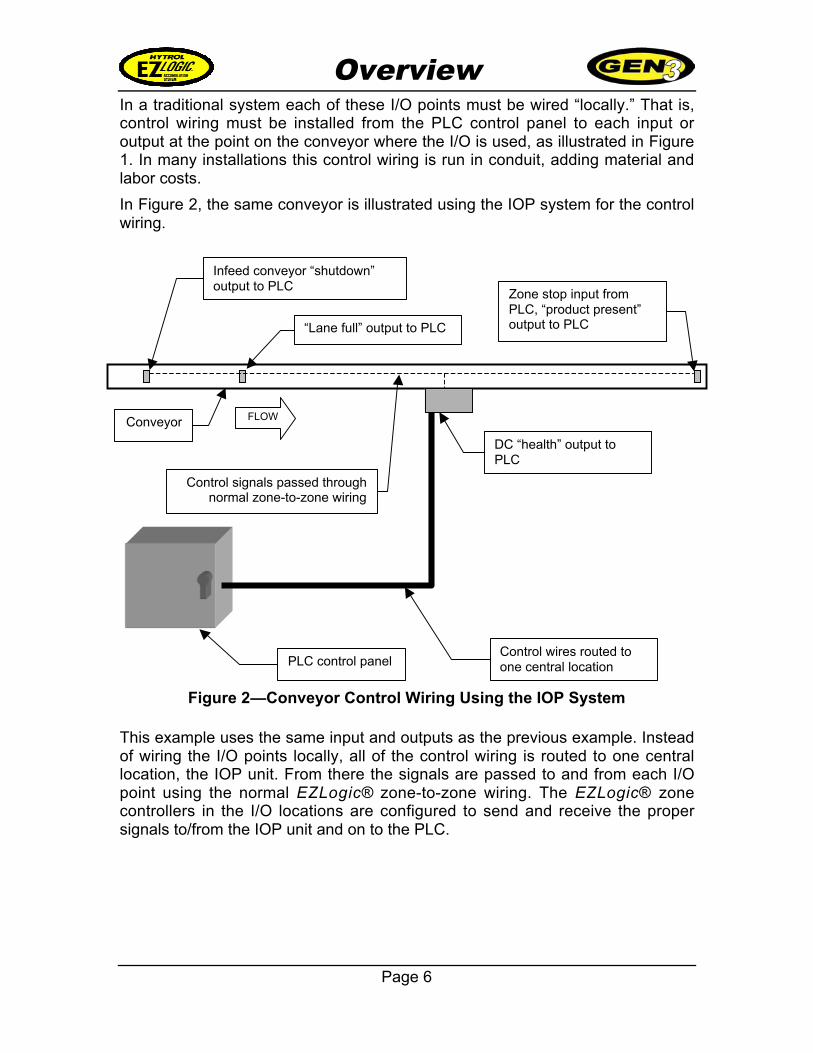
In a traditional system each of these I/O points must be wired “locally.” That is,control wiring must be installed from the PLC control panel to each input oroutput at the point on the conveyor where the I/O is used, as illustrated in Figure1. In many installations this control wiring is run in conduit, adding material andlabor costs.
In Figure 2, the same conveyor is illustrated using the IOP system for the controlwiring.
This example uses the same input and outputs as the previous example. Insteadof wiring the I/O points locally, all of the control wiring is routed to one centrallocation, the IOP unit. From there the signals are passed to and from each I/Opoint using the normal EZLogic® zone-to-zone wiring. The EZLogic® zonecontrollers in the I/O locations are configured to send and receive the propersignals to/from the IOP unit and on to the PLC.
Figure 2—Conveyor Control Wiring Using the IOP System
FLOW
Infeed conveyor “shutdown”output to PLC
“Lane full” output to PLC
DC “health” output toPLC
Zone stop input fromPLC, “product present”output to PLC
PLC control panelControl wires routed toone central location
Conveyor
Control signals passed throughnormal zone-to-zone wiring
Overview
Page 7
IOP AdvantagesThe IOP system offers several advantages to the integrator, installer, and enduser. Some of these advantages are listed below:
• Reduced installation costs—The number of conduit runs and junctionboxes required, as well as the labor required to install them, is greatlyreduced. This eliminates the cost of these items from the installationequation.
• Easy to reconfigure—Inputs and outputs can be moved to other zoneson the conveyor without having to run new conduit and wiring. I/O can bereconfigured by physically moving zone controllers or by changing themthrough software.
• Central location for installation, I/O checking, andtroubleshooting—Since all control wiring goes to one location, installing,debugging, and troubleshooting inputs and outputs is simplified.
• Can be used for “peer-to-peer” communication betweencontrollers—A signal from one zone controller may be used as an inputto another zone controller several zones away, using the IOP system,without running any wires.
Components
Page 8
Components
There are four key components of the EZLogic® accumulation system that arerequired to use IOP control functionality. These work with the other componentsof the system to provide a feature-rich zero-pressure conveyor control package.The four key IOP components are:
• IOP unit
• IOP I/O board(s) installed in the IOP unit
• Enhanced EZLogic® zone controllers in locations where I/O operationsare required
• Genesis™ configuration software and PC adapter
IOP UnitThe IOP (Input/Output/Power) unit is a key component of the EZLogic® system.The IOP unit performs two tasks:
The unit provides power to the other EZLogic® components. It converts 100-130 VAC 1ph, or 210-250 VAC 1ph input power into the 27 VDC power requiredby EZLogic®.
The unit is the “hub” and controller for the IOP control wiring system. All IOPsignals are passed through the IOP unit, and all control wiring is connected here.
Components
Page 9
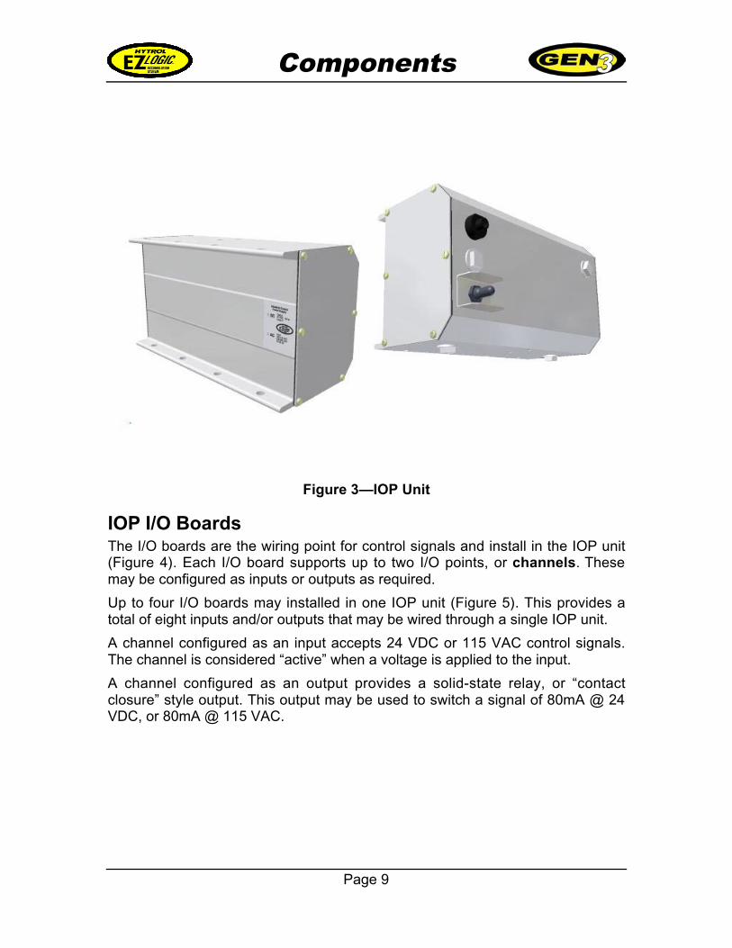
Figure 3—IOP Unit
IOP I/O BoardsThe I/O boards are the wiring point for control signals and install in the IOP unit(Figure 4). Each I/O board supports up to two I/O points, or channels. Thesemay be configured as inputs or outputs as required.
Up to four I/O boards may installed in one IOP unit (Figure 5). This provides atotal of eight inputs and/or outputs that may be wired through a single IOP unit.
A channel configured as an input accepts 24 VDC or 115 VAC control signals.The channel is considered “active” when a voltage is applied to the input.
A channel configured as an output provides a solid-state relay, or “contactclosure” style output. This output may be used to switch a signal of 80mA @ 24VDC, or 80mA @ 115 VAC.
Components
Page 10
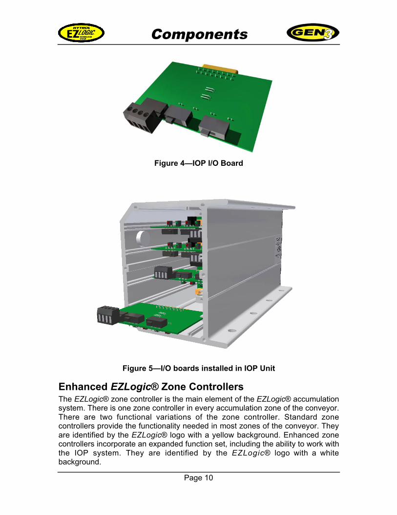
Figure 4—IOP I/O Board
Figure 5—I/O boards installed in IOP Unit
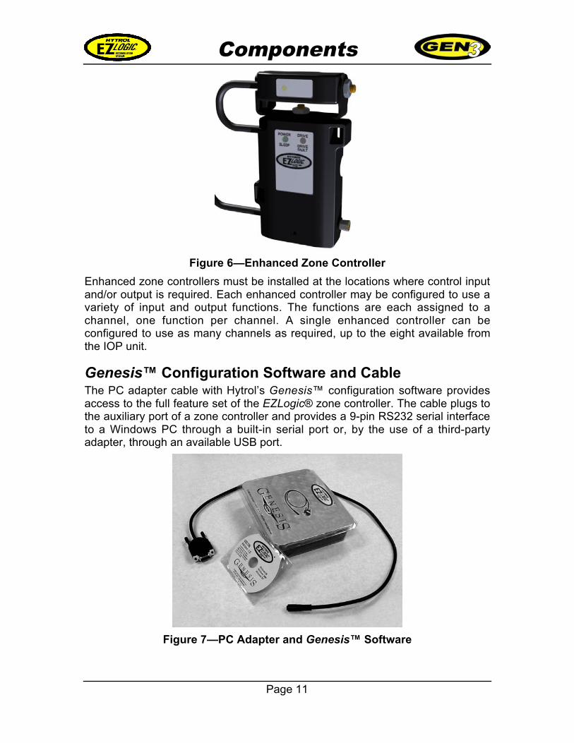
Enhanced EZLogic® Zone ControllersThe EZLogic® zone controller is the main element of the EZLogic® accumulationsystem. There is one zone controller in every accumulation zone of the conveyor.There are two functional variations of the zone controller. Standard zonecontrollers provide the functionality needed in most zones of the conveyor. Theyare identified by the EZLogic® logo with a yellow background. Enhanced zonecontrollers incorporate an expanded function set, including the ability to work withthe IOP system. They are identified by the EZLogic® logo with a whitebackground.
Components
Page 11
Figure 6—Enhanced Zone Controller
Enhanced zone controllers must be installed at the locations where control inputand/or output is required. Each enhanced controller may be configured to use avariety of input and output functions. The functions are each assigned to achannel, one function per channel. A single enhanced controller can beconfigured to use as many channels as required, up to the eight available fromthe IOP unit.
Genesis™ Configuration Software and CableThe PC adapter cable with Hytrol’s Genesis™ configuration software providesaccess to the full feature set of the EZLogic® zone controller. The cable plugs tothe auxiliary port of a zone controller and provides a 9-pin RS232 serial interfaceto a Windows PC through a built-in serial port or, by the use of a third-partyadapter, through an available USB port.
Figure 7—PC Adapter and Genesis™ Software
Installation & Setup
Page 12
Installation and Setup
Hytrol zero-pressure accumulation conveyors equipped with the EZLogic®system are pre-assembled at the factory. The proper setup procedure variesfrom conveyor model to conveyor model. The information in this manual refers totypical installations and, while accurate, may not be complete. Please refer to theinstallation and maintenance manual for your specific conveyor model forinformation about the physical setup of your conveyor.
This section describes the basic installation and setup of the componentsrequired for IOP control communications. For specific information about zonecontroller removal and installation, IOP unit installation, etc, please refer to the“EZLogic® Gen3 Component Manual.”
The following steps are used to set up the IOP system:
1. . . System layout/component selection
2. . . I/O board setup and installation
3. . . IOP unit setup and installation
4. . . Enhanced zone controller setup and installation.
System Layout/Component SelectionThe conveyor layout should be considered when selecting the requiredcomponents for IOP communications. There are three basic layouts that may beused when setting up IOP control wiring. They are:
• Single IOP unit
• Multiple IOP units, one IOP unit used as a wiring hub
• Multiple IOP units used as wiring hubs
Installation & Setup
Page 13
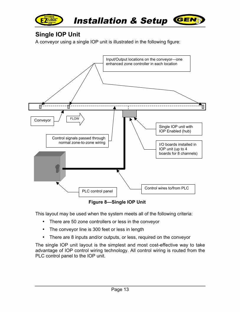
Single IOP UnitA conveyor using a single IOP unit is illustrated in the following figure:
This layout may be used when the system meets all of the following criteria:
• There are 50 zone controllers or less in the conveyor
• The conveyor line is 300 feet or less in length
• There are 8 inputs and/or outputs, or less, required on the conveyor
The single IOP unit layout is the simplest and most cost-effective way to takeadvantage of IOP control wiring technology. All control wiring is routed from thePLC control panel to the IOP unit.
Figure 8—Single IOP Unit
FLOW
Input/Output locations on the conveyor—oneenhanced zone controller in each location
PLC control panelControl wires to/from PLC
Conveyor
Control signals passed throughnormal zone-to-zone wiring
Single IOP unit withIOP Enabled (hub)
I/O boards installed inIOP unit (up to 4boards for 8 channels)
Installation & Setup
Page 14
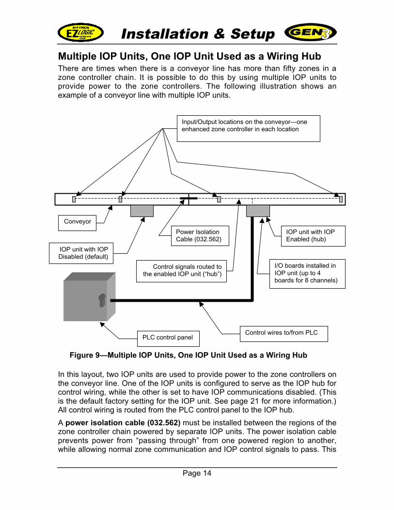
Multiple IOP Units, One IOP Unit Used as a Wiring HubThere are times when there is a conveyor line has more than fifty zones in azone controller chain. It is possible to do this by using multiple IOP units toprovide power to the zone controllers. The following illustration shows anexample of a conveyor line with multiple IOP units.
In this layout, two IOP units are used to provide power to the zone controllers onthe conveyor line. One of the IOP units is configured to serve as the IOP hub forcontrol wiring, while the other is set to have IOP communications disabled. (Thisis the default factory setting for the IOP unit. See page 21 for more information.)All control wiring is routed from the PLC control panel to the IOP hub.
A power isolation cable (032.562) must be installed between the regions of thezone controller chain powered by separate IOP units. The power isolation cableprevents power from “passing through” from one powered region to another,while allowing normal zone communication and IOP control signals to pass. This
Figure 9—Multiple IOP Units, One IOP Unit Used as a Wiring Hub
Input/Output locations on the conveyor—oneenhanced zone controller in each location
PLC control panelControl wires to/from PLC
Conveyor
Control signals routed tothe enabled IOP unit (“hub”)
IOP unit with IOPEnabled (hub)
I/O boards installed inIOP unit (up to 4boards for 8 channels)
IOP unit with IOPDisabled (default)
Power IsolationCable (032.562)
Installation & Setup
Page 15
cable prevents electrical interference between multiple power sources in thesame zone controller chain.
This layout may be used when the system meets all the following criteria:
• The conveyor line is 300 feet or less in length
• There are 8 inputs and/or outputs, or less, required on the conveyor line
• No more than 50 enhanced zone controllers have I/O assigned to IOPchannels
This layout offers the advantage that all inputs/outputs for the entire conveyorline are conveniently routed through one IOP hub.
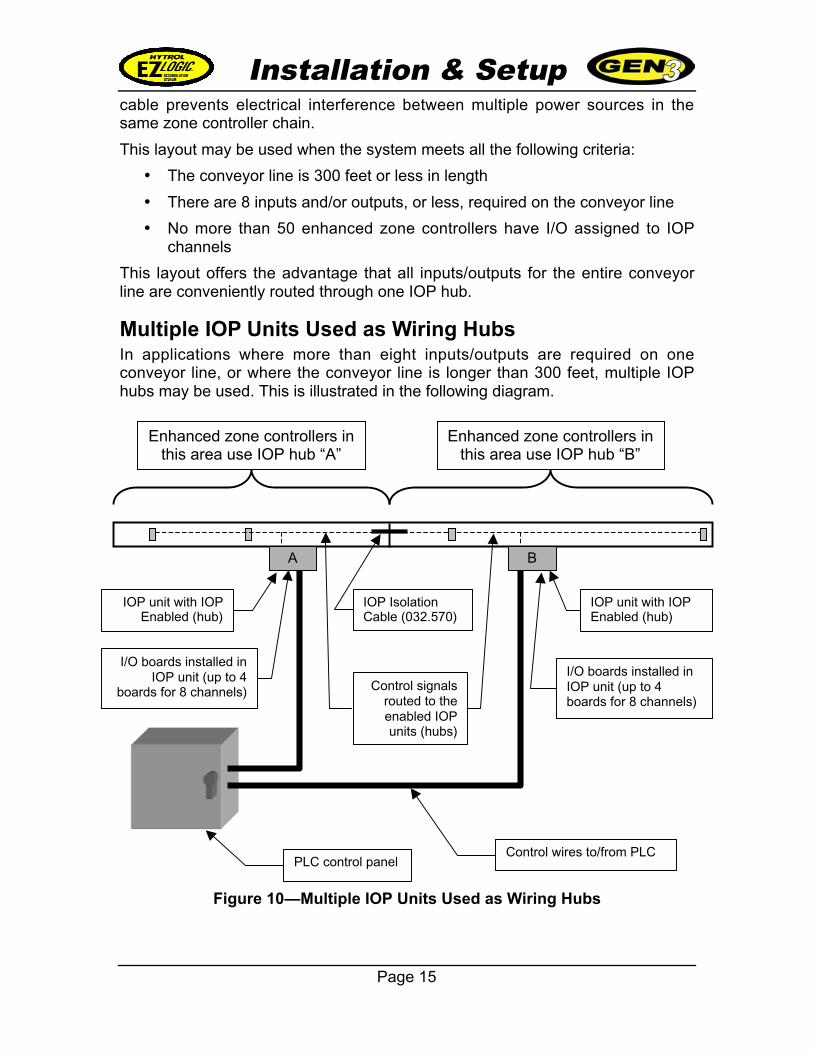
Multiple IOP Units Used as Wiring HubsIn applications where more than eight inputs/outputs are required on oneconveyor line, or where the conveyor line is longer than 300 feet, multiple IOPhubs may be used. This is illustrated in the following diagram.
Figure 10—Multiple IOP Units Used as Wiring Hubs
B
PLC control panelControl wires to/from PLC
Control signalsrouted to theenabled IOPunits (hubs)
IOP unit with IOPEnabled (hub)
I/O boards installed inIOP unit (up to 4boards for 8 channels)
A
IOP unit with IOPEnabled (hub)
IOP IsolationCable (032.570)
I/O boards installed inIOP unit (up to 4
boards for 8 channels)
Enhanced zone controllers inthis area use IOP hub “A”
Enhanced zone controllers inthis area use IOP hub “B”
Installation & Setup
Page 16
In this layout, two IOP units are used to provide power to the zone controllers onthe conveyor line. Both units are also configured to serve as IOP hubs for controlwiring.
The conveyor is divided into two IOP regions by an IOP isolation cable(032.570). This cable is similar to the power isolation cable in that it preventspower from “passing through” from one region to another, and allows normalzone communication to pass. However, the IOP isolation cable also prevents IOPcontrol signals from passing between regions. This allows each IOP hub tocontrol its associated region independently of the other.
This layout may be used when the system meets all the following criteria:
• Each conveyor region is 300 feet or less in length
• There are 8 inputs and/or outputs, or less, required in each conveyorregion
• No more than 50 enhanced zone controllers in each region have I/Oassigned to IOP channels
This layout allows the use of more than eight inputs/outputs on the sameconveyor line. It also allows the use of IOP control wiring on units longer than300 feet.
I/O Board Setup and InstallationThe IOP I/O boards are the connection point for control wiring from the PLCcontrol panel. Each I/O board supports two IOP communications channels.These channels may be configured for use as inputs, outputs, or one of each.
What are IOP Channels?The term “IOP channels” refers to the eight communications signals that areavailable through a single IOP unit. These channels are identified as “IOPchannel 1” through “IOP channel 8”. They provide connection between thecontrol signals connected to the I/O boards and the enhanced zone controllers inthe system.
A channel becomes “active”, or on, when either:
• There is an active input signal from the PLC to the appropriate I/O board,or
• An enhanced zone controller has an output assigned to that channel thatis active.
An “active” channel has the following effect on IOP components:
• If the I/O board I/O point for that channel is set to “output” then that outputto the PLC becomes active (“contact” is closed)
• If an enhanced zone controller has an input assigned to that channel, theinput becomes active in the zone controller.
Installation & Setup
Page 17
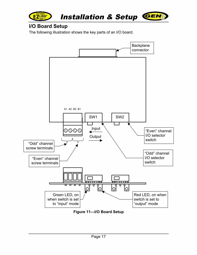
I/O Board SetupThe following illustration shows the key parts of an I/O board.
Figure 11—I/O Board Setup
Backplaneconnector
A1 A2 B2 B1
“Even” channelI/O selectorswitch
“Odd” channelI/O selectorswitch
“Even” channelscrew terminals
“Odd” channelscrew terminals
Red LED, on whenswitch is set to“output” mode
Green LED, onwhen switch is set
to “input” mode
Input
Output
SW1 SW2
Installation & Setup
Page 18
The following is a description of the components of the I/O board identified aboveand their purpose:
Backplane ConnectorThe backplane connector connects the I/O board to the backplane inside the IOPunit.
Screw TerminalsThe screw terminals are where control wires from the PLC are wired to the I/Oboard. This is a convenient 4-position “plug in” screw terminal, which means thatthe control wires are connected by screw clamps to a plug, which is then pluggedinto the I/O board.
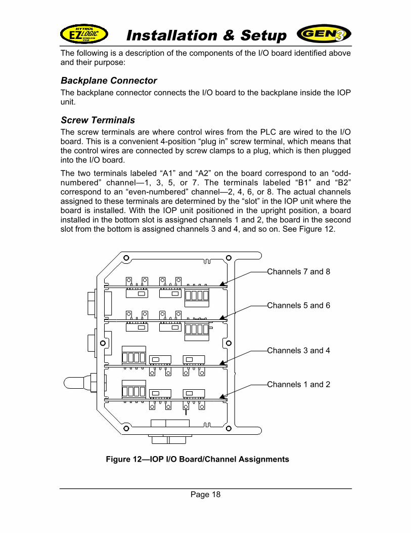
The two terminals labeled “A1” and “A2” on the board correspond to an “odd-numbered” channel—1, 3, 5, or 7. The terminals labeled “B1” and “B2”correspond to an “even-numbered” channel—2, 4, 6, or 8. The actual channelsassigned to these terminals are determined by the “slot” in the IOP unit where theboard is installed. With the IOP unit positioned in the upright position, a boardinstalled in the bottom slot is assigned channels 1 and 2, the board in the secondslot from the bottom is assigned channels 3 and 4, and so on. See Figure 12.
Figure 12—IOP I/O Board/Channel Assignments
Channels 1 and 2
Channels 3 and 4
Channels 5 and 6
Channels 7 and 8
Installation & Setup
Page 19
The inputs/outputs on these screw terminals are not polarity-sensitive.
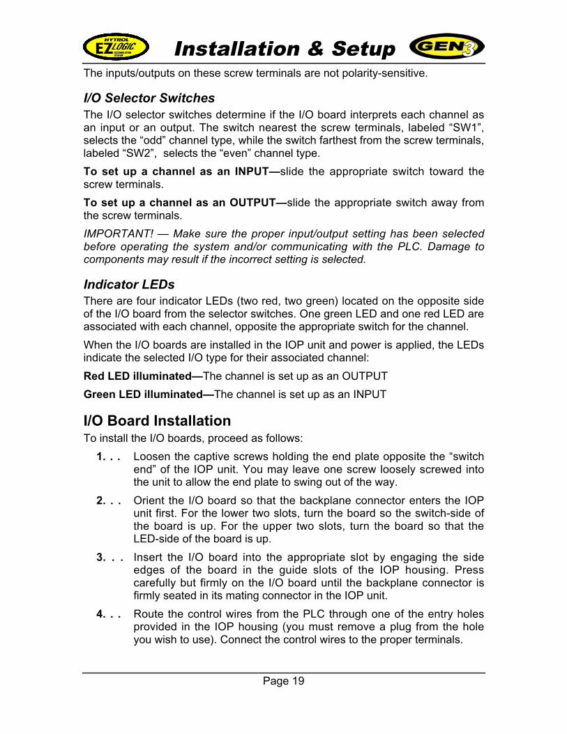
I/O Selector SwitchesThe I/O selector switches determine if the I/O board interprets each channel asan input or an output. The switch nearest the screw terminals, labeled “SW1”,selects the “odd” channel type, while the switch farthest from the screw terminals,labeled “SW2”, selects the “even” channel type.
To set up a channel as an INPUT—slide the appropriate switch toward thescrew terminals.
To set up a channel as an OUTPUT—slide the appropriate switch away fromthe screw terminals.
IMPORTANT! — Make sure the proper input/output setting has been selectedbefore operating the system and/or communicating with the PLC. Damage tocomponents may result if the incorrect setting is selected.
Indicator LEDsThere are four indicator LEDs (two red, two green) located on the opposite sideof the I/O board from the selector switches. One green LED and one red LED areassociated with each channel, opposite the appropriate switch for the channel.
When the I/O boards are installed in the IOP unit and power is applied, the LEDsindicate the selected I/O type for their associated channel:
Red LED illuminated—The channel is set up as an OUTPUT
Green LED illuminated—The channel is set up as an INPUT
I/O Board InstallationTo install the I/O boards, proceed as follows:
1. . . Loosen the captive screws holding the end plate opposite the “switchend” of the IOP unit. You may leave one screw loosely screwed intothe unit to allow the end plate to swing out of the way.
2. . . Orient the I/O board so that the backplane connector enters the IOPunit first. For the lower two slots, turn the board so the switch-side ofthe board is up. For the upper two slots, turn the board so that theLED-side of the board is up.
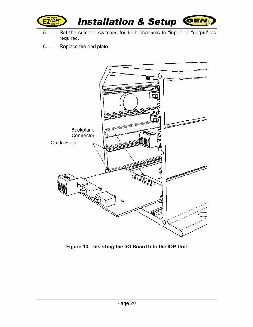
3. . . Insert the I/O board into the appropriate slot by engaging the sideedges of the board in the guide slots of the IOP housing. Presscarefully but firmly on the I/O board until the backplane connector isfirmly seated in its mating connector in the IOP unit.
4. . . Route the control wires from the PLC through one of the entry holesprovided in the IOP housing (you must remove a plug from the holeyou wish to use). Connect the control wires to the proper terminals.
Installation & Setup
Page 20
5. . . Set the selector switches for both channels to “input” or “output” asrequired.
6. . . Replace the end plate.
Figure 13—Inserting the I/O Board Into the IOP Unit
Guide Slots
BackplaneConnector
Installation & Setup
Page 21
IOP Unit Setup and InstallationInstallation of the IOP unit is described in the “EZLogic® Gen3 ComponentManual”. Please be sure to follow all instructions found in that manual wheninstalling the IOP unit.
In most cases the IOP unit is shipped from the factory with no I/O boardsinstalled and with IOP hub capability disabled. In order to use the IOP unit as anIOP wiring hub, one or more I/O boards must be installed in the IOP unit and IOPhub capability must be enabled.
Installing I/O Boards in the IOP UnitFollow the instructions on page 19 to set up and install the I/O board(s) in theIOP unit.
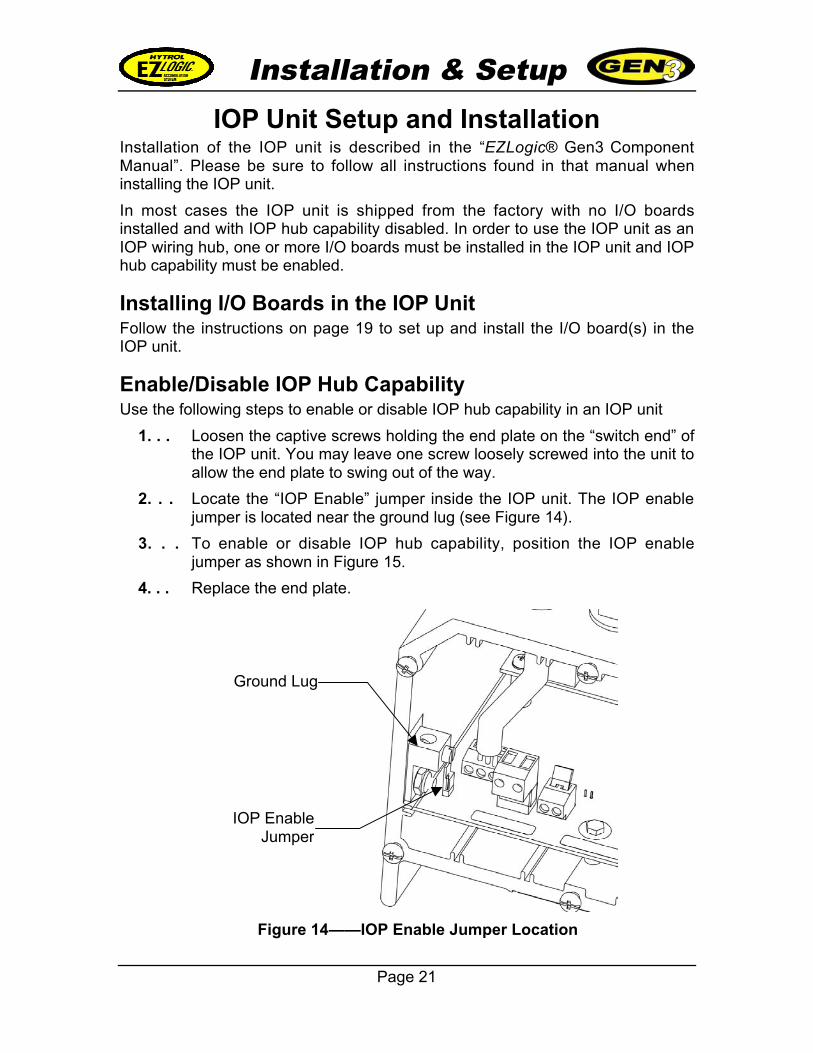
Enable/Disable IOP Hub CapabilityUse the following steps to enable or disable IOP hub capability in an IOP unit
1. . . Loosen the captive screws holding the end plate on the “switch end” ofthe IOP unit. You may leave one screw loosely screwed into the unit toallow the end plate to swing out of the way.
2. . . Locate the “IOP Enable” jumper inside the IOP unit. The IOP enablejumper is located near the ground lug (see Figure 14).
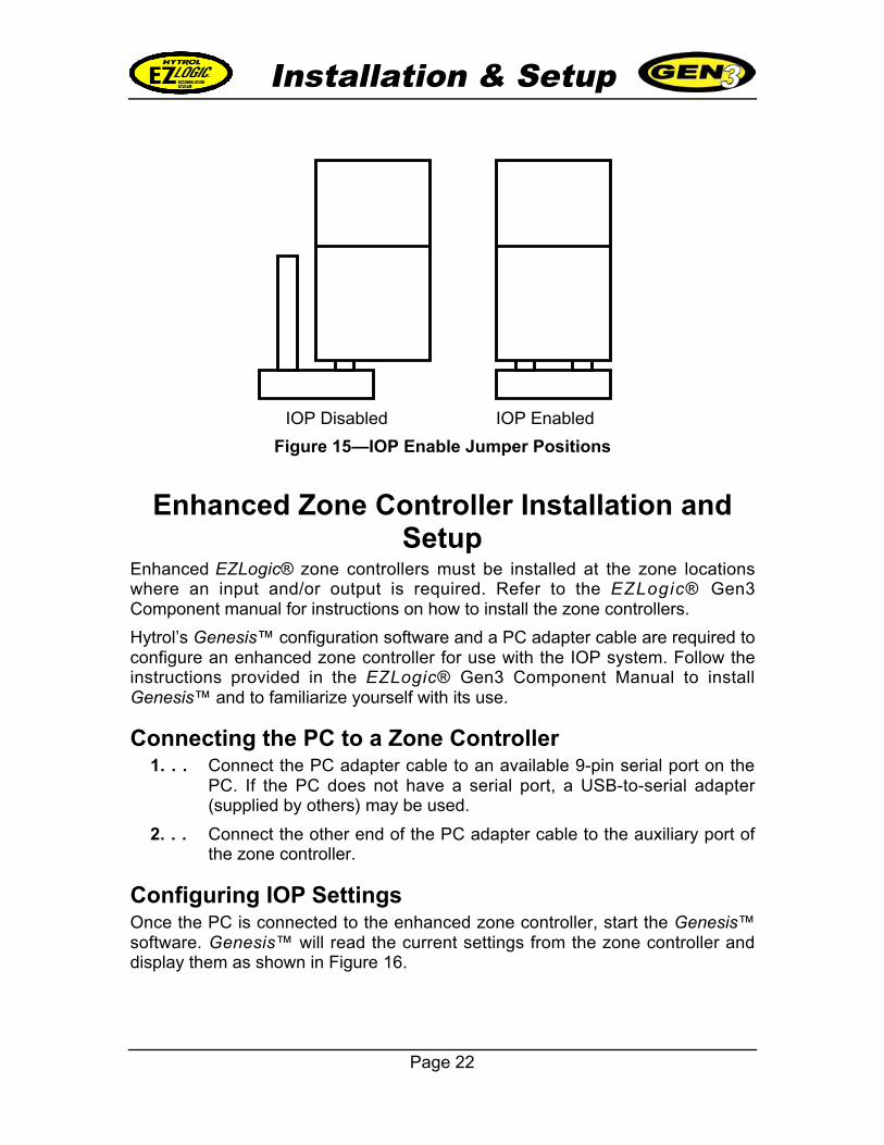
3. . . To enable or disable IOP hub capability, position the IOP enablejumper as shown in Figure 15.
4. . . Replace the end plate.
Figure 14——IOP Enable Jumper Location
Ground Lug
IOP EnableJumper
Installation & Setup
Page 22
Enhanced Zone Controller Installation andSetup
Enhanced EZLogic® zone controllers must be installed at the zone locationswhere an input and/or output is required. Refer to the EZLogic® Gen3Component manual for instructions on how to install the zone controllers.
Hytrol’s Genesis™ configuration software and a PC adapter cable are required toconfigure an enhanced zone controller for use with the IOP system. Follow theinstructions provided in the EZLogic® Gen3 Component Manual to installGenesis™ and to familiarize yourself with its use.
Connecting the PC to a Zone Controller 1. . . Connect the PC adapter cable to an available 9-pin serial port on the
PC. If the PC does not have a serial port, a USB-to-serial adapter(supplied by others) may be used.
2. . . Connect the other end of the PC adapter cable to the auxiliary port ofthe zone controller.
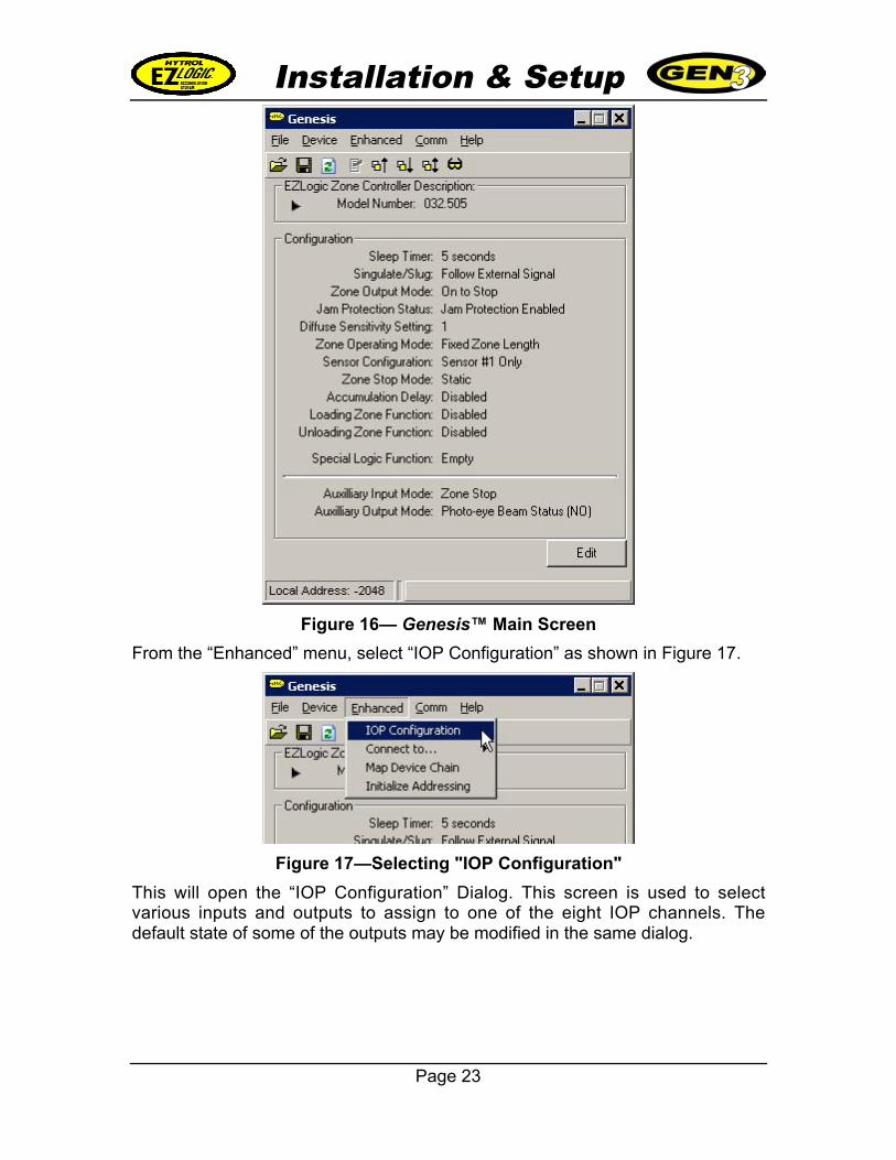
Configuring IOP SettingsOnce the PC is connected to the enhanced zone controller, start the Genesis™software. Genesis™ will read the current settings from the zone controller anddisplay them as shown in Figure 16.
Figure 15—IOP Enable Jumper Positions
IOP Disabled IOP Enabled
Installation & Setup
Page 23
Figure 16— Genesis™ Main Screen
From the “Enhanced” menu, select “IOP Configuration” as shown in Figure 17.
Figure 17—Selecting "IOP Configuration"
This will open the “IOP Configuration” Dialog. This screen is used to selectvarious inputs and outputs to assign to one of the eight IOP channels. Thedefault state of some of the outputs may be modified in the same dialog.
Installation & Setup
Page 24
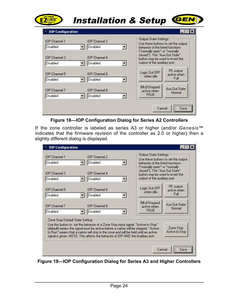
Figure 18—IOP Configuration Dialog for Series A2 Controllers
If the zone controller is labeled as series A3 or higher (and/or Genesis™indicates that the firmware revision of the controller as 2.0 or higher) then aslightly different dialog is displayed.
Figure 19—IOP Configuration Dialog for Series A3 and Higher Controllers
Installation & Setup
Page 25
IOP Channel BoxesThe IOP channel boxes allow you to configure the IOP channel settings. Oneinput or output may be assigned to a channel. Inputs/outputs for this zonecontroller may be assigned to any or all channels, as required.
Each channel has a list of available inputs and outputs that may be assigned inthe zone controller to that channel. The following inputs and outputs areavailable:
Disabled
This selection disables IOP communication with the channel by this zonecontroller.
Zone Stop Input
This selection causes the zone controller to interpret an active signal on thischannel as a zone stop input.
Slug Control Input
This selection causes the zone controller to interpret an active signal on thischannel as a “slug” signal. When the zone controller receives a slug signal itsends a signal to all other zone controllers in the chain to operate in slug mode.
Wake-Up Input
This selection causes the zone controller to interpret an active signal on thischannel as a “wake-up” signal. When the zone controller receives this signal it“wakes up” (if it is in sleep mode). If the zone controller is in the infeed zone ofthe controller chain, selecting this input will allow the zone to “go to sleep” until itdetects a load or the wake-up signal becomes active.
Logic Input
This selection causes the zone controller to interpret an active signal on thischannel as an input to a special logic function. If there is a special logic functionloaded into the zone controller that uses a logic input (such as the “Zone Kill”function), the logic function will “see” the input and use it in the operation of thefunction.
Directional Input
This selection causes the zone controller to interpret an active signal on thischannel as a directional input. When the zone controller receives a directionalsignal it generates a “reverse direction” signal that is sent to the other zonecontrollers in the chain. To use the reverse feature, the following componentsmust be used:
• Enhanced remote zone controllers (032.507), Series A3 (firmware revision2.0) or later, in all zones of the reversing conveyor
• Dual transducers in all zones
Installation & Setup
Page 26
• Genesis™ software and PC adapter (to configure this setting)
If a reverse input is inactive, EZLogic® operates in the default forward direction(defined by the way the cordsets are installed) using transducer #1 as thesensor. If a reverse input is active, EZLogic® operates in the reverse direction,using transducer #2 as the sensor. NOTE: The directional input signal onlyaffects the logical operation of the EZLogic® controls. It does not reverse thedirection of the conveyor’s drive mechanism. The conveyor drive itself must bereversed to operate in the reverse direction.
Transducer Output
This selection causes the zone controller to assign a transducer (sensor) outputto this channel. When the sensor of the zone controller detects a carton a signalis sent to the channel.
Blocked/Stopped Output
This selection causes the zone controller to assign a “zone blocked and stopped”output to this channel. When the zone controller both sees a carton and hasstopped driving (indicating that cartons are accumulated back to this point) asignal is sent to the channel.
Directional Output
This selection causes the zone controller to assign an “direction of flow” output tothis channel. An output signal is given when the zone controller is operating inreverse mode. This output may be used when an action needs to be triggered onanother conveyor or other device when the conveyor is operating in reversemode. NOTE: reverse mode is only available when using enhanced remote zonecontrollers (032.507) labeled Series A3” or later (and/or with firmware revision2.0 or later) and dual transducers.
Logic Output
This selection causes the zone controller to assign an output generated by aspecial logic function to this channel. If there is a special logic function loadedthat generates a logic output (such as the “PE On-Delay” and “PE Off-Delay”functions) that output is sent to the channel.
Jam Detected
This selection causes the zone controller to assign a “jam detected” output to thischannel. If the zone controller is operating in “slug mode” and detects a jam, thissignal is sent to the channel. The signal is only generated when this specificcontroller detects the jam, so to be effective multiple zone controllers shouldhave “jam detected” assigned to the same channel.
Short Circuit, Low Voltage, Over Current
These selections cause the zone controller to assign the named output to thischannel. If the selected condition exists in the zone controller a signal is sent tothe channel. The signal is only generated when the selected condition exists in
Installation & Setup
Page 27
this zone controller. However, multiple enhanced zone controllers may beconfigured to assign the output to the same channel. This provides a way tomonitor some line conditions through the IOP system.
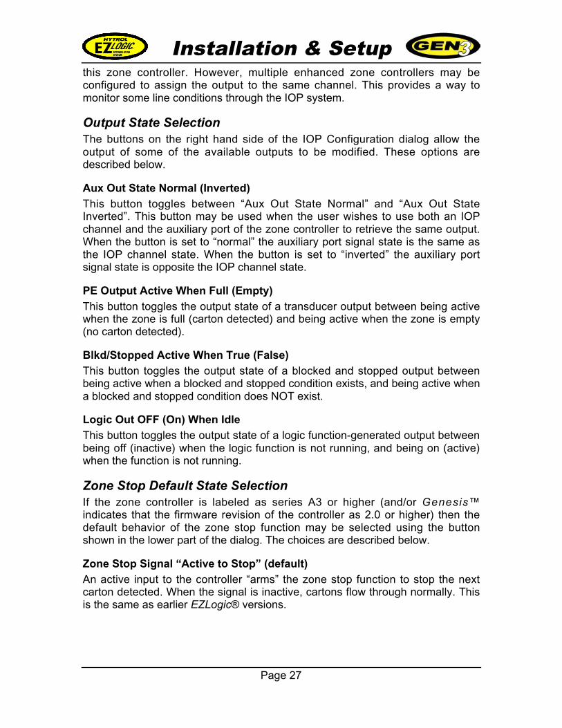
Output State SelectionThe buttons on the right hand side of the IOP Configuration dialog allow theoutput of some of the available outputs to be modified. These options aredescribed below.
Aux Out State Normal (Inverted)
This button toggles between “Aux Out State Normal” and “Aux Out StateInverted”. This button may be used when the user wishes to use both an IOPchannel and the auxiliary port of the zone controller to retrieve the same output.When the button is set to “normal” the auxiliary port signal state is the same asthe IOP channel state. When the button is set to “inverted” the auxiliary portsignal state is opposite the IOP channel state.
PE Output Active When Full (Empty)
This button toggles the output state of a transducer output between being activewhen the zone is full (carton detected) and being active when the zone is empty(no carton detected).
Blkd/Stopped Active When True (False)
This button toggles the output state of a blocked and stopped output betweenbeing active when a blocked and stopped condition exists, and being active whena blocked and stopped condition does NOT exist.
Logic Out OFF (On) When Idle
This button toggles the output state of a logic function-generated output betweenbeing off (inactive) when the logic function is not running, and being on (active)when the function is not running.
Zone Stop Default State SelectionIf the zone controller is labeled as series A3 or higher (and/or Genesis™indicates that the firmware revision of the controller as 2.0 or higher) then thedefault behavior of the zone stop function may be selected using the buttonshown in the lower part of the dialog. The choices are described below.
Zone Stop Signal “Active to Stop” (default)
An active input to the controller “arms” the zone stop function to stop the nextcarton detected. When the signal is inactive, cartons flow through normally. Thisis the same as earlier EZLogic® versions.
Installation & Setup
Page 28
Zone Stop Signal “Active to Run” (“failsafe”)
The zone stop function is “armed” when the input is inactive. An active input tothe controller “disarms” the zone stop feature. This means that a carton thatenters the zone will be stopped by default. An active signal is required to releasethe carton. This setting may be used at the discharge zone of any conveyor whenit is important that product is held back should a controls failure occur.
To Configure an Enhanced Zone Controller: 1. . . Connect the PC to the zone controller and start Genesis™.
2. . . Click on “Enhanced—IOP Configuration” to bring up the IOPConfiguration dialog
3. . . Select the IOP channel you wish to use. Be sure to select the channelthat corresponds to the I/O board channel to which the PLC controlwires are connected.
4. . . Select the type of input or output you wish to assign to the channel.
5. . . Set the required output state for the selected output, if applicable.
6. . . If another channel is being assigned in the same zone controller,repeat steps 3 through 5 for the remaining channel(s).
Installation & Setup
Page 29
Notes on IOP System ConfigurationThe following are some tips and reminders about IOP system configuration forreference:
• Once a zone controller has been configured and has one or moreinputs/outputs assigned to an IOP channel, the configuration is maintaineduntil changed again using the Genesis™ software. This feature makes iteasy to move an input or output to another zone. For example, supposean enhanced zone controller is located in the 10th zone from the dischargeend of the conveyor and is configured to provide a transducer (photo-eye)output to the PLC. If the user later decides that this output should belocated in the 12th zone, the zone controllers in zones 10 and 12 maysimply be swapped. The configured controller, now located in zone 12, willcontinue to provide the output to the PLC from the new location.
• Keep a record of the location of zone controllers configured for IOPcommunication along with their configuration information (input/outputtype, channel assignments, etc). This will prove very valuable should anychanges be required in the future.
• Only one IOP unit should be configured as an IOP hub (IOPcommunications enabled) in one zone controller chain, unless an IOPisolation cable is used between IOP regions.
• A zone controller chain using IOP communications and one IOP hubshould not exceed 300 feet in length.
• No more than 50 enhanced zone controllers may be configured to use IOPcommunications with one IOP hub.
Operation
Page 30
IOP System Operation
The IOP system is a powerful tool for providing real-time communicationsbetween an EZLogic®-equipped conveyor and external controls. Once thecomponents have been installed and configured, the system is ready foroperation.
This section of the manual describes the basic operation of the IOP system.Read this section if you wish to have a more thorough understanding of how theIOP system works.
IOP ChannelsAs mentioned previously in this manual, the term “IOP channels” refers to theeight communications signals that are available through a single IOP unit. Thesechannels are identified as “IOP channel 1” through “IOP channel 8”. They provideconnection between the control signals connected to the I/O boards and theenhanced zone controllers in the system.
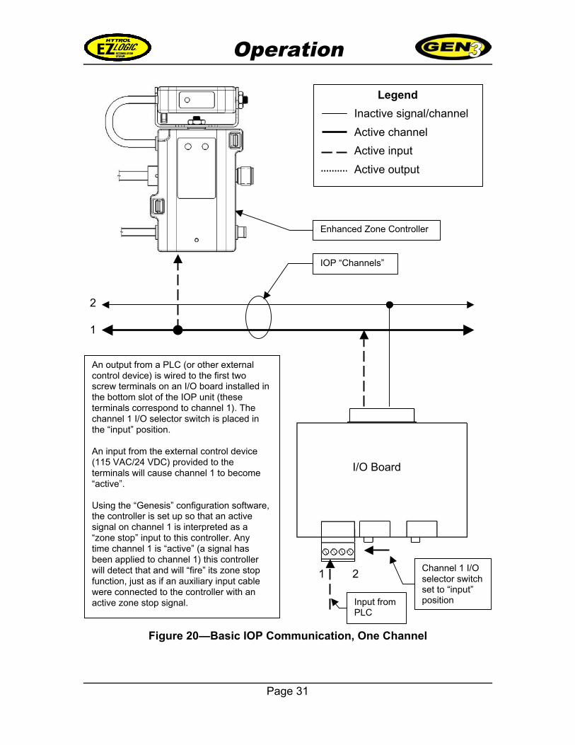
Figure 20 illustrates a basic IOP communication setup using one IOP channel,one enhanced zone controller, and one I/O board.
The I/O board supports two IOP channels. As described in the illustration, whenthe I/O board is installed in the bottom slot of the IOP unit, these two channelsare assigned as channel 1 and channel 2. In the illustration, channel 2 is notbeing used and is shown for reference only.
Since the example in the illustration is describing the signal as a zone stop input,the I/O selector switch for channel 1 is set to the “input” position. When an inputis applied to the channel 1 terminals, it causes channel 1 to become “active”.
The zone controller is configured to look for an active signal on channel 1 and tointerpret this as a zone stop input. Any time channel 1 becomes active the zonestop function of the zone controller will be triggered.
Operation
Page 31
Figure 20—Basic IOP Communication, One Channel
Legend
Inactive signal/channel
Active channel
Active input
Active output
1
2
1 2Channel 1 I/Oselector switchset to “input”position
An output from a PLC (or other externalcontrol device) is wired to the first twoscrew terminals on an I/O board installed inthe bottom slot of the IOP unit (theseterminals correspond to channel 1). Thechannel 1 I/O selector switch is placed inthe “input” position.
An input from the external control device(115 VAC/24 VDC) provided to theterminals will cause channel 1 to become“active”.
Using the “Genesis” configuration software,the controller is set up so that an activesignal on channel 1 is interpreted as a“zone stop” input to this controller. Anytime channel 1 is “active” (a signal hasbeen applied to channel 1) this controllerwill detect that and will “fire” its zone stopfunction, just as if an auxiliary input cablewere connected to the controller with anactive zone stop signal. Input from
PLC
IOP “Channels”
Enhanced Zone Controller
I/O Board
Operation
Page 32
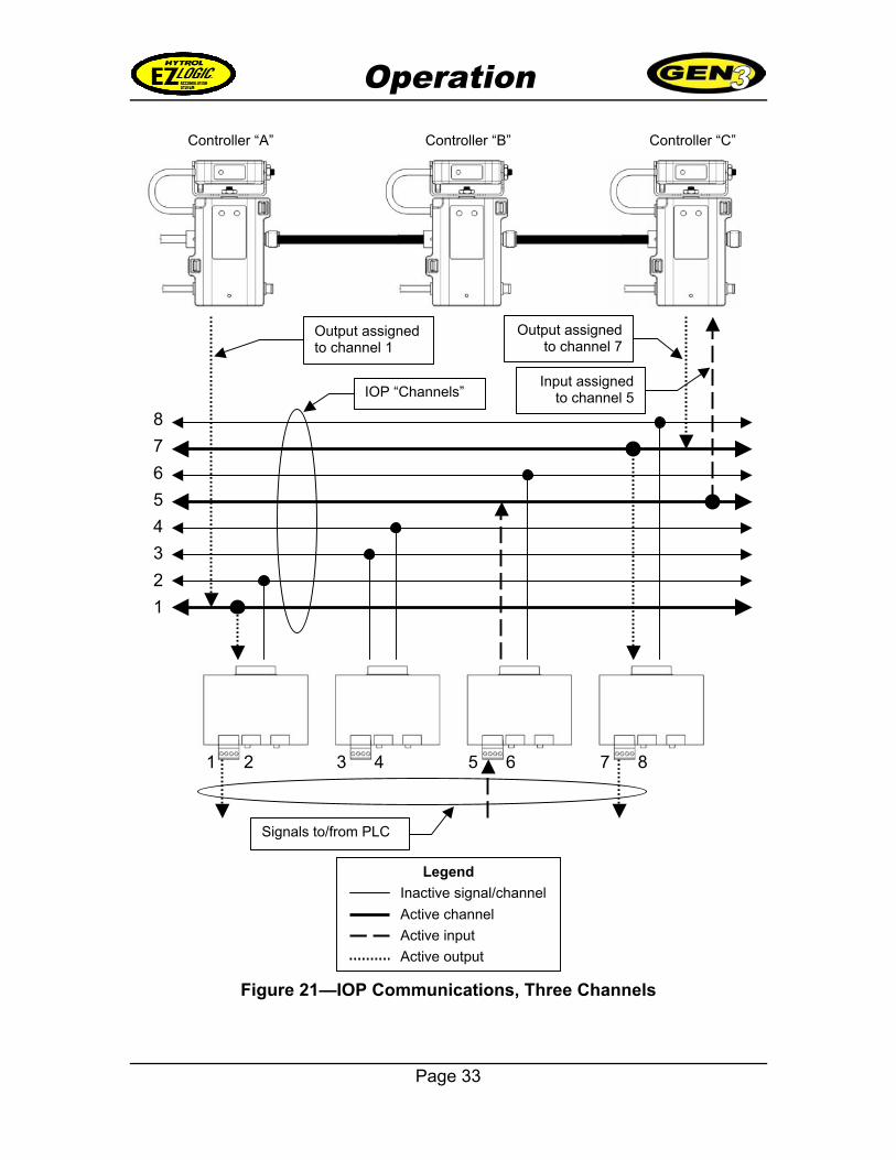
Figure 21 shows a system with the maximum of four I/O boards installed in theIOP unit. Three of the channels, 1, 5, and 7, are being used for IOPcommunications. The other five channels are not being used, and are shown forreference only.
In the example, controller “A” has an output assigned to channel 1. This may beany of the outputs described under “IOP Channel Boxes” beginning on page 25.When the zone controller triggers this output signal, it is sent to channel 1, whichbecomes “active.” This in turn triggers the output on the channel 1 terminals ofthe first I/O board, thus sending the signal to the PLC.
Controller “C” has an output assigned to channel 7. Again, this may be any of theoutputs described under “IOP Channel Boxes” beginning on page 25. When thezone controller triggers this output signal, it is sent to channel 7, which becomes“active.” This in turn triggers the output on the channel 7 terminals of the fourthI/O board, thus sending the signal to the PLC.
Controller “C” also has an input assigned to channel 5. This may be any of theinputs described under “IOP Channel Boxes” beginning on page 25. Whenchannel 5 becomes active as a result of a signal from the PLC to the channel 5terminals on the third I/O board, controller “C” interprets this as the assignedinput and responds accordingly.
Operation
Page 33
Figure 21—IOP Communications, Three Channels
Legend
Inactive signal/channel
Active channel
Active input
Active output
8
7
6
5
4
3
2
1
1 2
IOP “Channels”
3 4 5 6 7 8
Controller “A” Controller “B” Controller “C”
Output assignedto channel 1
Output assignedto channel 7
Input assignedto channel 5
Signals to/from PLC
Operation
Page 34
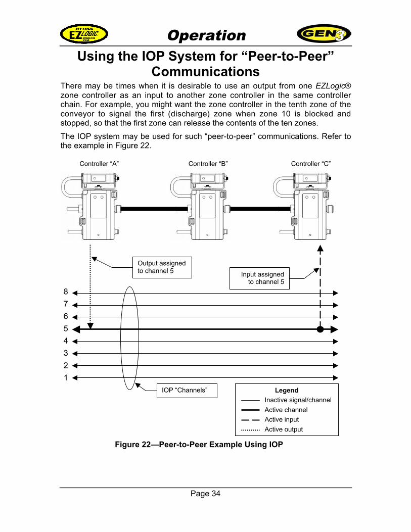
Using the IOP System for “Peer-to-Peer”Communications
There may be times when it is desirable to use an output from one EZLogic®zone controller as an input to another zone controller in the same controllerchain. For example, you might want the zone controller in the tenth zone of theconveyor to signal the first (discharge) zone when zone 10 is blocked andstopped, so that the first zone can release the contents of the ten zones.
The IOP system may be used for such “peer-to-peer” communications. Refer tothe example in Figure 22.
Figure 22—Peer-to-Peer Example Using IOP
Legend
Inactive signal/channel
Active channel
Active input
Active output
8
7
6
5
4
3
2
1
IOP “Channels”
Controller “A” Controller “B” Controller “C”
Output assignedto channel 5 Input assigned
to channel 5
Operation
Page 35
In this example, controller “A” has an output assigned to IOP channel 5.Whenever controller “A” sends the output, channel 5 becomes “active”.
Controller “C” has an input that is also assigned to channel 5. Whenever channel5 is “active”, controller “C” interprets this as the assigned input. Therefore whencontroller “A” sends the output and activates channel 5, controller “C” receives aninput.
This type of “peer-to-peer” communication does not require the use of I/O boardsin the IOP unit. However, if an I/O board is present in the third I/O slot of the IOPunit, it can also receive the output or produce the input on channel 5.
Specifications
Page 36
IOP Communications SystemSpecifications
I/O Board
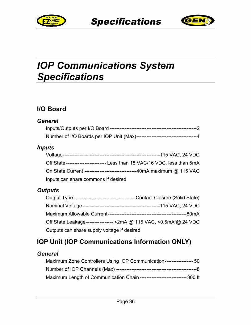
GeneralInputs/Outputs per I/O Board ----------------------------------------------------2
Number of I/O Boards per IOP Unit (Max)------------------------------------4
InputsVoltage----------------------------------------------------------115 VAC, 24 VDC
Off State ------------------------ Less than 18 VAC/16 VDC, less than 5mA
On State Current -------------------------------40mA maximum @ 115 VAC
Inputs can share commons if desired
OutputsOutput Type ------------------------------------ Contact Closure (Solid State)
Nominal Voltage ----------------------------------------------115 VAC, 24 VDC
Maximum Allowable Current-----------------------------------------------80mA
Off State Leakage---------------- <2mA @ 115 VAC, <0.5mA @ 24 VDC
Outputs can share supply voltage if desired
IOP Unit (IOP Communications Information ONLY)
GeneralMaximum Zone Controllers Using IOP Communication----------------- 50
Number of IOP Channels (Max) ------------------------------------------------8
Maximum Length of Communication Chain ----------------------------300 ft

Specifications
Page 37
Enhanced Zone Controller (IOP Information ONLY)
Available InputsZone Stop
Slug Control
Wake-Up
Logic
Direction of flow
Available OutputsTransducer (photo-eye)
Blocked/Stopped
Direction of flow
Logic
Jam Detected
Short Circuit
Low Voltage
Over current
Output StatesAux Out State Normal/Inverted
PE Output Active When Empty/Full
Blocked/Stopped Output Active When True/False
Logic Out OFF/ON When Idle
Specifications
Page 38
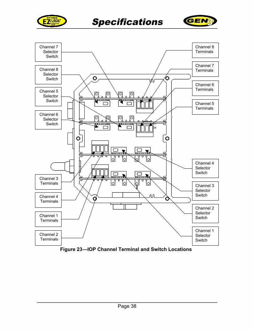
Figure 23—IOP Channel Terminal and Switch Locations
Channel 1Terminals
Channel 2Terminals
Channel 3Terminals
Channel 4Terminals
Channel 7Terminals
Channel 8Terminals
Channel 5Terminals
Channel 6Terminals
Channel 6Selector
Switch
Channel 5Selector
Switch
Channel 8Selector
Switch
Channel 7Selector
Switch
Channel 4SelectorSwitch
Channel 3SelectorSwitch
Channel 2SelectorSwitch
Channel 1SelectorSwitch

Page 39
This page intentionally left blank

HYTROL CONVEYOR COMPANY, INC.2020 Hytrol Drive
Jonesboro, Arkansas 72401
Phone: (870) 935-3700www.hytrol.com
EFFECTIVE March 2007


![12[1]. IOP](https://img.pdfslide.us/doc/110x75/5475bb2eb4af9fa30a8b5d8f/121-iop.jpg)