Embed Size (px)
Citation preview

Performance Motion Devices, Inc.80 Central Street
Boxborough, MA 01719
ION/CME Digital DriveUser’s Manual
Revision 1.1 April 18, 2012
ii ION/CME Digital Drive User’s Manual
NOTICE
This document contains proprietary and confidential information of Performance Motion Devices, Inc., and is pro-tected by federal copyright law. The contents of this document may not be disclosed to third parties, translated, copied, or duplicated in any form, in whole or in part, without the express written permission of PMD.
The information contained in this document is subject to change without notice. No part of this document may be reproduced or transmitted in any form, by any means, electronic or mechanical, for any purpose, without the express written permission of PMD.
Copyright 1998–2012 by Performance Motion Devices, Inc.
Magellan, ION, Magellan/ION, Pro-Motion, C-Motion and VB-Motion are trademarks of Performance Motion Devices, Inc.
ION/CME Digital Drive User’s Manual iii
Warranty
PMD warrants performance of its products to the specifications applicable at the time of sale in accordance with PMD’s standard warranty. Testing and other quality control techniques are utilized to the extent PMD deems necessary to support this warranty. Specific testing of all parameters of each device is not necessarily performed, except those mandated by government requirements.
Performance Motion Devices, Inc. (PMD) reserves the right to make changes to its products or to discontinue any product or service without notice, and advises customers to obtain the latest version of relevant information to verify, before placing orders, that information being relied on is current and complete. All products are sold subject to the terms and conditions of sale supplied at the time of order acknowledgement, including those pertaining to warranty, patent infringement, and limitation of liability.
Safety Notice
Certain applications using semiconductor products may involve potential risks of death, personal injury, or severe property or environmental damage. These products are not designed, authorized, or warranted to be suitable for use in life support devices or systems or other critical applications. Inclusion of PMD products in such applications is un-derstood to be fully at the customer’s risk.
In order to minimize risks associated with the customer’s applications, adequate design and operating safeguards must be provided by the customer to minimize inherent procedural hazards.
Disclaimer
PMD assumes no liability for applications assistance or customer product design. PMD does not warrant or represent that any license, either express or implied, is granted under any patent right, copyright, mask work right, or other in-tellectual property right of PMD covering or relating to any combination, machine, or process in which such products or services might be or are used. PMD’s publication of information regarding any third party’s products or services does not constitute PMD’s approval, warranty, or endorsement thereof.
iv ION/CME Digital Drive User’s Manual
Related Documents
Magellan Motion Processor User’s Guide
Complete description of the Magellan Motion Processor features and functions with detailed theory of itsoperation.
Magellan Motion Processor Programmer’s Command Reference
Descriptions of all Magellan Motion Processor commands, with coding syntax and examples, listed alphabetically for quick reference.
Pro-Motion User’s Guide
User’s guide to Pro-Motion, the easy-to-use motion system development tool and performance optimizer.Pro-Motion is a sophisticated, easy-to-use program which allows all motion parameters to be set and/orviewed, and allows all features to be exercised.
C-Motion Engine Development Tools Manual
Describes the C-Motion Engine Development Tools that allow user application code to be created andcompiled on a host PC, then downloaded, executed and monitored on a CME device C-Motion Enginemodule.
PMD Resource Access Protocol Programmer’s Reference
Describes the PMD Resource access Protocol (PRP) used for communication between the host and a PRPdevice, the software interfaces and binary protocols, the procedures and data types used for programs,software libraries and C-Motion library code.
Table of Contents
ION/CME Digital Drive User’s Manual v
Table of Contents
1. Introduction . . . . . . . . . . . . . . . . . . . . . . . . . . . . . . . . . . . . . . . . . . . . . . . . 91.1 ION Digital Drive Overview ............................................................................... 91.2 Features and Functions ........................................................................................ 10
2. Installation . . . . . . . . . . . . . . . . . . . . . . . . . . . . . . . . . . . . . . . . . . . . . . . . . 112.1 ION/CME Model Numbering ............................................................................. 112.2 ION/CME Developer’s Kits ................................................................................ 122.3 Required Hardware .............................................................................................. 122.4 ION/CME Hardware Configuration and Mounting ............................................ 132.5 Connector Pinouts and Wiring ............................................................................ 142.6 Software Installation ........................................................................................... 282.7 Communications Configuration .......................................................................... 282.8 Applying Power ................................................................................................... 292.9 Status LEDs ......................................................................................................... 302.10 First-Time System Verification ........................................................................... 31
3. Operation . . . . . . . . . . . . . . . . . . . . . . . . . . . . . . . . . . . . . . . . . . . . . . . . . . 393.1 ION/CME Block Diagram .................................................................................. 393.2 Communication Port ........................................................................................... 403.3 PWM Power Stage .............................................................................................. 403.4 DC Bus ................................................................................................................ 433.5 Trace Buffer ........................................................................................................ 443.6 Operational and Fault Modes .............................................................................. 45
4. ION/CME Control . . . . . . . . . . . . . . . . . . . . . . . . . . . . . . . . . . . . . . . . . . . 474.1 Communication Protocols ................................................................................... 474.2 ION/CME Access Basics .................................................................................... 484.3 Magellan Motion Processor Functions ................................................................ 484.4 General Purpose Digital I/O ................................................................................ 504.5 Analog Input ........................................................................................................ 524.6 C-Motion Engine Functions ................................................................................ 544.7 Communications Functions ................................................................................. 574.8 ION/CME Reset .................................................................................................. 594.9 Non-volatile Memory .......................................................................................... 604.10 Setting Module Defaults ...................................................................................... 614.11 ION/CME Command Summary .......................................................................... 62
5. Options and Accessories . . . . . . . . . . . . . . . . . . . . . . . . . . . . . . . . . . . . . . 635.1 Stub Cable Set ..................................................................................................... 635.2 Development Kit Cable and Plug Specifications ................................................ 645.3 Optional Heat Sink .............................................................................................. 675.4 Optional DIN Rail Adapter ................................................................................. 68
6. Electrical Signal Interfacing . . . . . . . . . . . . . . . . . . . . . . . . . . . . . . . . . . . 696.1 Motor Feedback ................................................................................................... 696.2 Auxiliary Position Input ...................................................................................... 716.3 Limit and Home Inputs ....................................................................................... 726.4 Position Capture Sources .................................................................................... 726.5 AxisIn and AxisOut Signals ................................................................................ 73
Table of Contents
vi ION/CME Digital Drive User’s Manual
6.6 /Enable and FaultOut Signals ................................................................746.7 General Purpose Digital Inputs and Outputs .........................................766.8 Analog Inputs ........................................................................................77
7. ION/CME Specifications ............................................................. 797.1 ION/CME Drive Ratings ..................................................................... 797.2 ION/CME Controller Performance ......................................................807.3 ION/CME Electrical .............................................................................817.4 ION/CME Protection Circuits ..............................................................837.5 ION/CME Connectors and Pinouts ......................................................837.6 ION/CME Mechanical ........................................................................867.7 ION/CME Environmental ...................................................................877.8 ION/CME Safety and Compliance ......................................................877.9 ION/CME Thermal Operating Curves .................................................87
Index . . . . . . . . . . . . . . . . . . . . . . . . . . . . . . . . . . . . . 89
List of Figures
ION/CME Digital Drive User’s Manual vii
List of FiguresFigure 2-1: Connector locator . . . . . . . . . . . . . . . . . . . . . . . . . . . . . . . . . . . . . . . . . . . . . . . . . . . . . . . .14Figure 2-2: Typical power wiring . . . . . . . . . . . . . . . . . . . . . . . . . . . . . . . . . . . . . . . . . . . . . . . . . . . . . .16Figure 2-3: Typical motor wiring . . . . . . . . . . . . . . . . . . . . . . . . . . . . . . . . . . . . . . . . . . . . . . . . . . . . . .17Figure 2-4: Recommended feedback wiring . . . . . . . . . . . . . . . . . . . . . . . . . . . . . . . . . . . . . . . . . . . . .19Figure 2-5: Recommended auxiliary encoder wiring . . . . . . . . . . . . . . . . . . . . . . . . . . . . . . . . . . . . . . .20Figure 2-6: Single encoder mode connections . . . . . . . . . . . . . . . . . . . . . . . . . . . . . . . . . . . . . . . . . . . .21Figure 2-7: Dual encoder mode connections . . . . . . . . . . . . . . . . . . . . . . . . . . . . . . . . . . . . . . . . . . . . .22Figure 2-8: Pulse & direction input connections . . . . . . . . . . . . . . . . . . . . . . . . . . . . . . . . . . . . . . . . . .23Figure 2-9: Typical I/O wiring . . . . . . . . . . . . . . . . . . . . . . . . . . . . . . . . . . . . . . . . . . . . . . . . . . . . . . . .24Figure 2-10: Indexer I/O wiring . . . . . . . . . . . . . . . . . . . . . . . . . . . . . . . . . . . . . . . . . . . . . . . . . . . . . . .25Figure 2-11: RS232/485 wiring . . . . . . . . . . . . . . . . . . . . . . . . . . . . . . . . . . . . . . . . . . . . . . . . . . . . . . .27Figure 2-12: Serial port connection . . . . . . . . . . . . . . . . . . . . . . . . . . . . . . . . . . . . . . . . . . . . . . . . . . . .28Figure 3-1: ION/CME block diagram . . . . . . . . . . . . . . . . . . . . . . . . . . . . . . . . . . . . . . . . . . . . . . . . . .39Figure 3-2: Simplified serial transceiver diagram . . . . . . . . . . . . . . . . . . . . . . . . . . . . . . . . . . . . . . . . .40Figure 4-1: ION/CME block diagram . . . . . . . . . . . . . . . . . . . . . . . . . . . . . . . . . . . . . . . . . . . . . . . . . .49Figure 4-2: Analog inputs simplified diagrams . . . . . . . . . . . . . . . . . . . . . . . . . . . . . . . . . . . . . . . . . . .53Figure 4-3: C-Motion Engine architecture . . . . . . . . . . . . . . . . . . . . . . . . . . . . . . . . . . . . . . . . . . . . . . .54Figure 5-1: ION/CME heat sink . . . . . . . . . . . . . . . . . . . . . . . . . . . . . . . . . . . . . . . . . . . . . . . . . . . . . . .67Figure 5-2: ION/CME with heat sink attached . . . . . . . . . . . . . . . . . . . . . . . . . . . . . . . . . . . . . . . . . . .67Figure 5-3: Attaching the optional DIN rail adapter . . . . . . . . . . . . . . . . . . . . . . . . . . . . . . . . . . . . . . .68Figure 5-4: ION mounted on DIN rail . . . . . . . . . . . . . . . . . . . . . . . . . . . . . . . . . . . . . . . . . . . . . . . . . .68Figure 6-1: Main encoder input circuits . . . . . . . . . . . . . . . . . . . . . . . . . . . . . . . . . . . . . . . . . . . . . . . . .69Figure 6-2: Encoder phasing diagram . . . . . . . . . . . . . . . . . . . . . . . . . . . . . . . . . . . . . . . . . . . . . . . . . .70Figure 6-3: Hall input circuits . . . . . . . . . . . . . . . . . . . . . . . . . . . . . . . . . . . . . . . . . . . . . . . . . . . . . . . .70Figure 6-4: Auxiliary encoder input circuits . . . . . . . . . . . . . . . . . . . . . . . . . . . . . . . . . . . . . . . . . . . . .71Figure 6-5: Limit and Home input circuits . . . . . . . . . . . . . . . . . . . . . . . . . . . . . . . . . . . . . . . . . . . . . . .72Figure 6-6: High Speed Capture circuit . . . . . . . . . . . . . . . . . . . . . . . . . . . . . . . . . . . . . . . . . . . . . . . . .73Figure 6-7: AxisIn circuit . . . . . . . . . . . . . . . . . . . . . . . . . . . . . . . . . . . . . . . . . . . . . . . . . . . . . . . . . . . .73Figure 6-8: AxisOut circuit . . . . . . . . . . . . . . . . . . . . . . . . . . . . . . . . . . . . . . . . . . . . . . . . . . . . . . . . . .74Figure 6-9: /Enable input circuit . . . . . . . . . . . . . . . . . . . . . . . . . . . . . . . . . . . . . . . . . . . . . . . . . . . . . .75Figure 6-10: FaultOut circuit . . . . . . . . . . . . . . . . . . . . . . . . . . . . . . . . . . . . . . . . . . . . . . . . . . . . . . . . .75Figure 6-11: Digital inputs circuit . . . . . . . . . . . . . . . . . . . . . . . . . . . . . . . . . . . . . . . . . . . . . . . . . . . . .76Figure 6-12: Digital outputs circuit . . . . . . . . . . . . . . . . . . . . . . . . . . . . . . . . . . . . . . . . . . . . . . . . . . . .77Figure 6-13: Digital I/O circuit . . . . . . . . . . . . . . . . . . . . . . . . . . . . . . . . . . . . . . . . . . . . . . . . . . . . . . .77Figure 6-14: Analog inputs simplified diagram . . . . . . . . . . . . . . . . . . . . . . . . . . . . . . . . . . . . . . . . . . .78Figure 7-1: ION/CME dimensions . . . . . . . . . . . . . . . . . . . . . . . . . . . . . . . . . . . . . . . . . . . . . . . . . . . . .86Figure 7-2: ION/CME derating curve for DC brush module . . . . . . . . . . . . . . . . . . . . . . . . . . . . . . . . .87Figure 7-3: ION/CME derating curves for brushless DC module . . . . . . . . . . . . . . . . . . . . . . . . . . . . .88Figure 7-4: ION/CME derating curves for step motor module . . . . . . . . . . . . . . . . . . . . . . . . . . . . . . .88

List of Figures
viii ION/CME Digital Drive User’s Manual
This page intentionally left blank.
ION/CME Digital Drive User’s Manual 9999
11. IntroductionIn This ChapterION Digital Drive OverviewFeatures and Functions
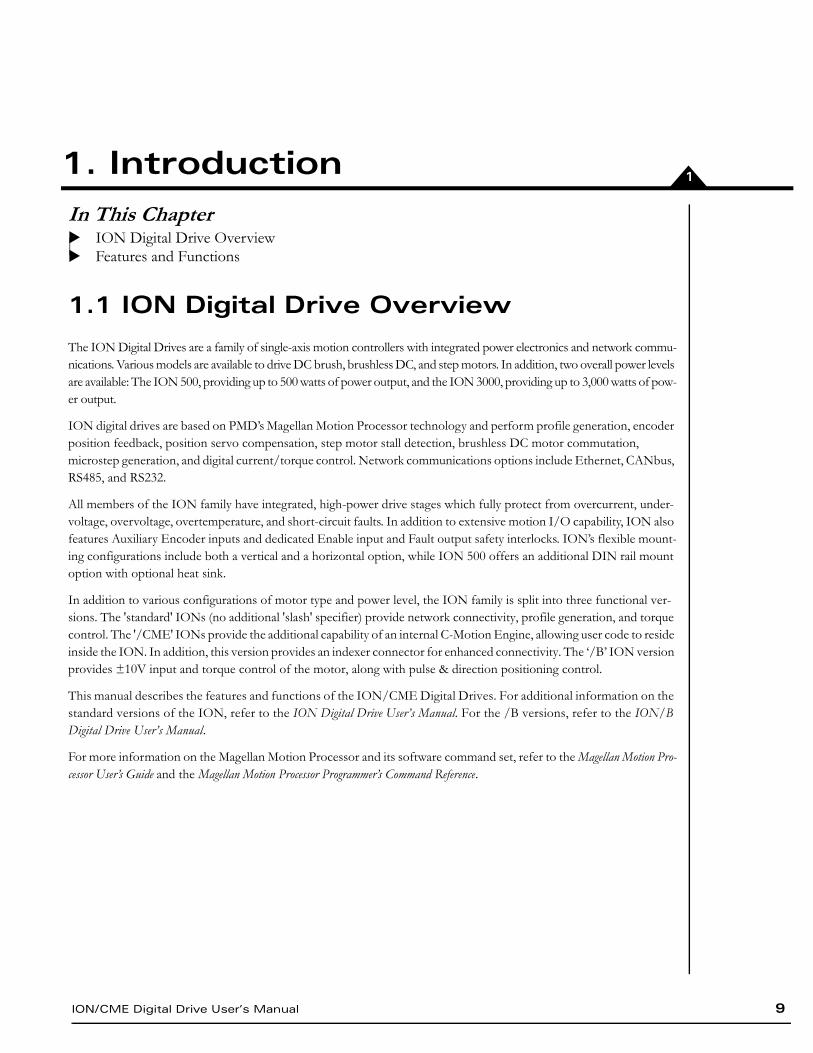
1.1 ION Digital Drive Overview
The ION Digital Drives are a family of single-axis motion controllers with integrated power electronics and network commu-nications. Various models are available to drive DC brush, brushless DC, and step motors. In addition, two overall power levels are available: The ION 500, providing up to 500 watts of power output, and the ION 3000, providing up to 3,000 watts of pow-er output.
ION digital drives are based on PMD’s Magellan Motion Processor technology and perform profile generation, encoder position feedback, position servo compensation, step motor stall detection, brushless DC motor commutation,microstep generation, and digital current/torque control. Network communications options include Ethernet, CANbus, RS485, and RS232.
All members of the ION family have integrated, high-power drive stages which fully protect from overcurrent, under-voltage, overvoltage, overtemperature, and short-circuit faults. In addition to extensive motion I/O capability, ION also features Auxiliary Encoder inputs and dedicated Enable input and Fault output safety interlocks. ION’s flexible mount-ing configurations include both a vertical and a horizontal option, while ION 500 offers an additional DIN rail mount option with optional heat sink.
In addition to various configurations of motor type and power level, the ION family is split into three functional ver-sions. The 'standard' IONs (no additional 'slash' specifier) provide network connectivity, profile generation, and torque control. The '/CME' IONs provide the additional capability of an internal C-Motion Engine, allowing user code to reside inside the ION. In addition, this version provides an indexer connector for enhanced connectivity. The ‘/B’ ION version provides ±10V input and torque control of the motor, along with pulse & direction positioning control.
This manual describes the features and functions of the ION/CME Digital Drives. For additional information on the standard versions of the ION, refer to the ION Digital Drive User’s Manual. For the /B versions, refer to the ION/B Digital Drive User’s Manual.
For more information on the Magellan Motion Processor and its software command set, refer to the Magellan Motion Pro-cessor User’s Guide and the Magellan Motion Processor Programmer’s Command Reference.
Introduction
10 ION/CME Digital Drive User’s Manual
1
1.2 Features and Functions
At the heart of ION/CME are the Magellan Motion Processor and the C-Motion Engine (CME). This member of the ION family provides an extensive list of control functions, including:
Host communications over Ethernet, RS232, or RS485
Ability to download and execute user application code in the ION
256 KB of programmable user code space
Code execution rate up to 96 MIPS (million instructions per second)
Advanced C-Motion Engine development tools
Trajectory generation, including trapezoidal and S-curve point-to-point profiling, velocity contouring, and electronic gearing modes
Advanced PID position loop with integration limit, derivative sample time, velocity and accelerationfeedforward, output bias, dual biquad filters, and support for dual encoder feedback
Indexer connector providing additional digital I/O and 16-bit analog input
Two encoder input channels capable of up to 10 Mcounts per second
Sinusoidal and six-step (Hall) brushless DC commutation modes
Microstepping outputs with up to 256 microsteps per step
Digital current loop with choice of standard A/B or Field Oriented Control (FOC) for both brushless DC and step motors
Single phase current loop for DC brush motors
Pulse and direction input
High-efficiency MOSFET power stages with versions for single-phase brush DC motors, two-phase step motors, and three-phase brushless DC motors
I2t current foldback limiting
Selectable 20 kHz and 40 kHz PWM frequencies to support a broad range of motor inductance
Overcurrent, short circuit, overvoltage, undervoltage, and overtemperature protection
Single supply operation. An onboard DC/DC converter supplies all internal circuitry and also provides 5V for encoders and other external I/O.
Enable input and Fault output safety interlock
Differential or single-ended encoder input buffers for all encoder channels
Signal conditioning buffers and analog filters on all I/O signals
ION comes packaged in a rugged enclosure with flexible mounting options and reliable signal and power connectors. ION is fully RoHS compliant and CE marked.
Introduction
ION/CME Digital Drive User’s Manual 11
22. InstallationIn This ChapterION/CME Model NumberingION/CME Developer’s KitsRequired HardwareION/CME Hardware Configuration and MountingConnector Pinouts and WiringSoftware InstallationCommunications ConfigurationApplying PowerStatus LEDsFirst-Time System Verification
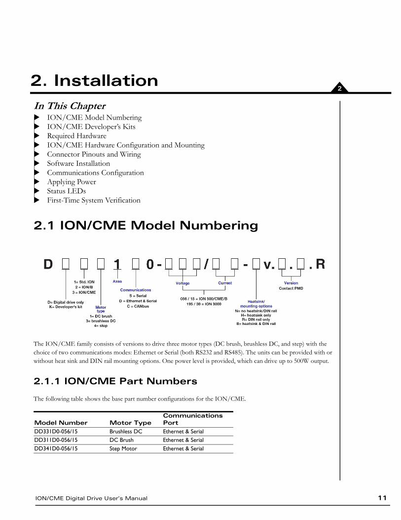
2.1 ION/CME Model Numbering
The ION/CME family consists of versions to drive three motor types (DC brush, brushless DC, and step) with the choice of two communications modes: Ethernet or Serial (both RS232 and RS485). The units can be provided with or without heat sink and DIN rail mounting options. One power level is provided, which can drive up to 500W output.
2.1.1 ION/CME Part Numbers
The following table shows the base part number configurations for the ION/CME.
Model Number Motor TypeCommunications Port
DD331D0-056/15 Brushless DC Ethernet & SerialDD311D0-056/15 DC Brush Ethernet & SerialDD341D0-056/15 Step Motor Ethernet & Serial
Installation
12 ION/CME Digital Drive User’s Manual
2
2.2 ION/CME Developer’s Kits
To facilitate initial system development and integration, ION/CME is offered in a Developer’s Kit version. A model number beginning with DK instead of DD specifies the Developer’s Kit version.
The following software and accessory products are included in the ION Developer’s Kit:
Pro-Motion CD and User’s Guide
C-Motion Engine Software Developer’s Kit, including:
A complete toolset for the creation of user-specific applications running on ION/CME or host
An open-source compiler and motion-control C libraries
PDF files of all documentation
C-Motion and VB-Motion CD including PDFs of all ION documentation
Communications cables with adapters (Ethernet and Serial)
Stub cable set – a complete set of cables with matching ION/CME connectors on one end and flying leads on the other
For more information on these accessory products, refer to Chapter 5, Options and Accessories.
2.2.1 Developer’s Kit Model Numbers
2.3 Required Hardware
To install an ION/CME Digital Drive, the following hardware is required:
A host controller. The recommended PC platform is an Intel (or compatible) processor, Pentium or better, one available COM port, 200MB of available disk space and a CD-ROM drive. The supported PC operating systems are Windows XP, Vista, and Windows 7.
An Ethernet port
For RS232 or RS485 communications, a PCI card, PCMCIA card, or USB adapter supporting the desired standard connected to the PC
Mounting screws to attach the ION module to your cabinet or system
Properly sized DC bus power supply
Step, DC brush, or brushless DC motor, with encoder as required by the application
Cables. Either the stub cable set that comes with ION/CME Developer’s Kits or custom cables designed for the system.
Limit switches and other I/O as required for the application
Model Number Motor TypeCommunications Port
DK331D0-056/15 Brushless DC Ethernet & SerialDK311D0-056/15 DC Brush Ethernet & SerialDK341D0-056/15 Step Motor Ethernet & Serial
Installation
ION/CME Digital Drive User’s Manual 13
2
2.4 ION/CME Hardware Configuration and Mounting
There are no user-settable switches, jumpers, or potentiometers within the ION/CME module. All hardware features are configurable from the host computer via the communications port.
Mount the module firmly in the desired orientation with adequate space to allow it to be effectively cooled. ION/CME is designed to allow maximum mounting flexibility.
2.4.1 ION/CME Mounting Options
Refer to Section 7.6, ION/CME Mechanical for information on mounting dimensions and mounting hole sizes for the ION/CME. Refer to Figure 2-1 for cable connection locations.
Cooling MethodRecommended Orientation
Recommended Mounting Surface Mounting Method
Coldplate Any Either Horizontal - 4 screwsVertical - 2 screws
Convection Vertical Back (small side) 2 screws or DIN rail adapterConvection with Optional Heat Sink
Vertical Back (small side) 2 screws or DIN rail adapter
Forced Air Any Either 2 or 4 screws, or DIN rail adapterForced Air with Optional Heat Sink
Any Back (small side) Horizontal - 4 screws Vertical - 2 screws
To minimize electrical noise problems, the metal base of the ION/CME enclosure should be grounded. This is usu-ally accomplished automatically when the module is mounted to a metal part of a grounded system. When mount-ed to a DIN rail using the optional DIN rail adapter or when mounted to a non-conductive or non-grounded surface, one of the free mounting holes can be used to attach a grounding wire. Note that to make proper elec-trical contact to the ION's mounting holes, it may be necessary to scrape off the ION's powder coating in this area. It is the responsibility of the user to ensure proper electrical conduction to the metal base of the ION/CME enclosure.
Installation
14 ION/CME Digital Drive User’s Manual
2
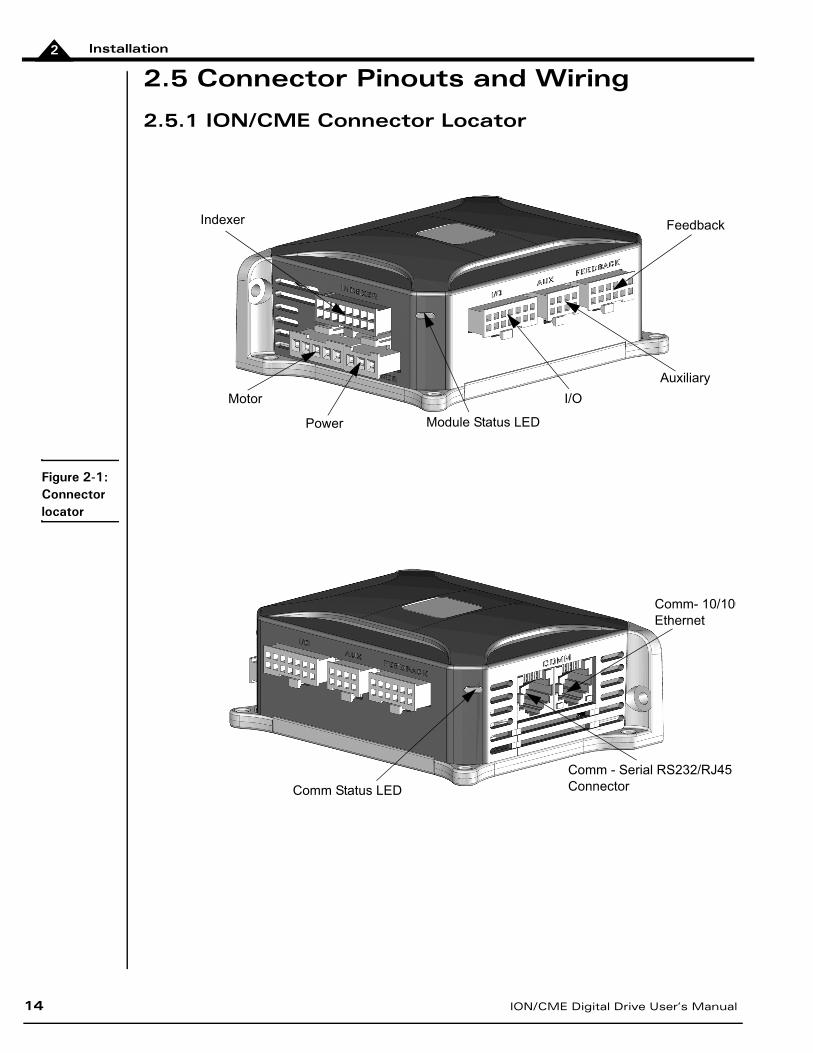
2.5 Connector Pinouts and Wiring
2.5.1 ION/CME Connector Locator
Module Status LEDPower
Feedback
Auxiliary
I/OMotor
Indexer
Comm- 10/100Ethernet
Comm - Serial RS232/RJ45ConnectorComm Status LED
Figure 2-1: Connector locator
Installation
ION/CME Digital Drive User’s Manual 15
2
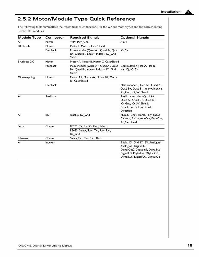
2.5.2 Motor/Module Type Quick Reference
The following table summarizes the recommended connections for the various motor types and the corresponding ION/CME modules:
Module Type Connector Required Signals Optional SignalsAll Power +HV, Pwr_Gnd AuxVDC brush Motor Motor+, Motor-, Case/Shield
Feedback Main encoder (Quad A+, Quad A-, Quad B+, Quad B-, Index+, Index-), IO_Gnd, Shield
IO_5V
Brushless DC Motor Motor A, Motor B, Motor C, Case/ShieldFeedback Main encoder (Quad A+, Quad A-, Quad
B+, Quad B-, Index+, Index-), IO_Gnd, Shield
Commutation (Hall A, Hall B,Hall C), IO_5V
Microstepping Motor Motor A+, Motor A-, Motor B+, Motor B-, Case/Shield
Feedback Main encoder (Quad A+, Quad A-, Quad B+, Quad B-, Index+, Index-), IO_Gnd, IO_5V, Shield
All Auxiliary Auxiliary encoder (Quad A+,Quad A-, Quad B+, Quad B-),IO_Gnd, IO_5V, Shield,Pulse+, Pulse-, Direction+, Direction-
All I/O /Enable, IO_Gnd +Limit, -Limit, Home, High Speed Capture, AxisIn, AxisOut, FaultOut, IO_5V, Shield
Serial Comm RS232: Tx, Rx, IO_Gnd, SelectRS485: Select, Tx+, Tx-, Rx+, Rx-, IO_Gnd
Ethernet Comm Select,Tx+, Tx-, Rx+, Rx-All Indexer Shield, IO_Gnd, IO_5V, AnalogIn-,
AnalogIn+, DigitalOut1, DigitalOut2, DigitalIn1, DigitalIn2, DigitalIn3, DigitalIn4, DigitalIO5, DigitalIO6, DigitalIO7, DigitalIO8
Installation
16 ION/CME Digital Drive User’s Manual
2
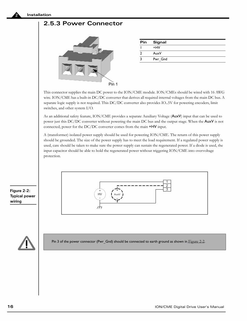
2.5.3 Power Connector
This connector supplies the main DC power to the ION/CME module. ION/CMEs should be wired with 16 AWG wire. ION/CME has a built-in DC/DC converter that derives all required internal voltages from the main DC bus. A separate logic supply is not required. This DC/DC converter also provides IO_5V for powering encoders, limit switches, and other system I/O.
As an additional safety feature, ION/CME provides a separate Auxiliary Voltage (AuxV) input that can be used to power just this DC/DC converter without powering the main DC bus and the output stage. When the AuxV is not connected, power for the DC/DC converter comes from the main +HV input.
A (transformer) isolated power supply should be used for powering ION/CME. The return of this power supply should be grounded. The size of the power supply has to meet the load requirement. If a regulated power supply is used, care should be taken to make sure the power supply can sustain the regenerated power. If a diode is used, the input capacitor should be able to hold the regenerated power without triggering ION/CME into overvoltage protection.
Pin Signal1 +HV
2 AuxV
3 Pwr_Gnd
Pin 3 of the power connector (Pwr_Gnd) should be connected to earth ground as shown in Figure 2-2.
Figure 2-2: Typical power wiring
1
23+
HV
-
+
AuxV
-
Pin 1
Installation
ION/CME Digital Drive User’s Manual 17
2
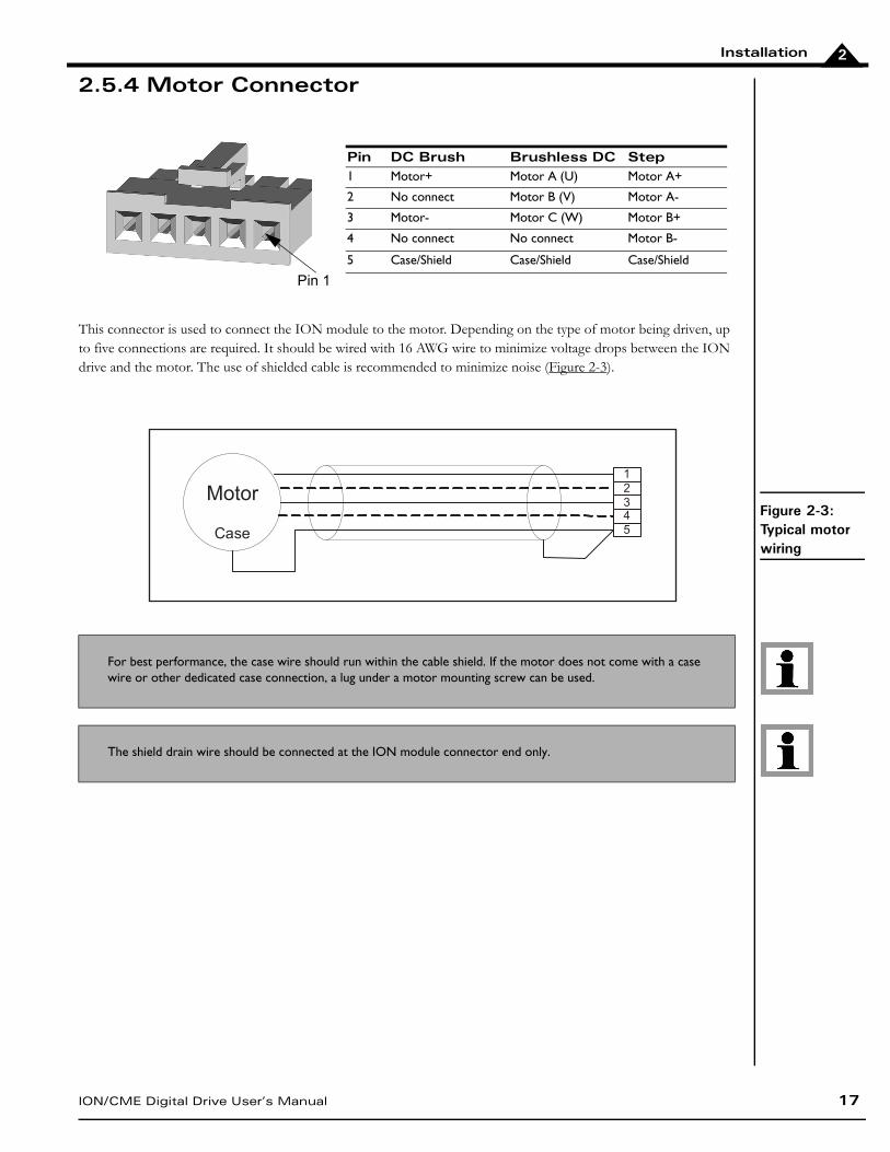
2.5.4 Motor Connector
This connector is used to connect the ION module to the motor. Depending on the type of motor being driven, up to five connections are required. It should be wired with 16 AWG wire to minimize voltage drops between the ION drive and the motor. The use of shielded cable is recommended to minimize noise (Figure 2-3).
Pin DC Brush Brushless DC Step1 Motor+ Motor A (U) Motor A+
2 No connect Motor B (V) Motor A-
3 Motor- Motor C (W) Motor B+
4 No connect No connect Motor B-
5 Case/Shield Case/Shield Case/Shield
For best performance, the case wire should run within the cable shield. If the motor does not come with a case wire or other dedicated case connection, a lug under a motor mounting screw can be used.
The shield drain wire should be connected at the ION module connector end only.
Pin 1
Motor
Case
1
2
34
5
Figure 2-3: Typical motor wiring
Installation
18 ION/CME Digital Drive User’s Manual
2
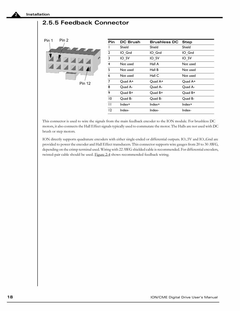
2.5.5 Feedback Connector
This connector is used to wire the signals from the main feedback encoder to the ION module. For brushless DC motors, it also connects the Hall Effect signals typically used to commutate the motor. The Halls are not used with DC brush or step motors.
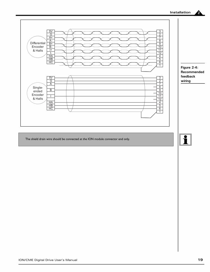
ION directly supports quadrature encoders with either single-ended or differential outputs. IO_5V and IO_Gnd are provided to power the encoder and Hall Effect transducers. This connector supports wire gauges from 20 to 30 AWG, depending on the crimp terminal used. Wiring with 22 AWG shielded cable is recommended. For differential encoders, twisted-pair cable should be used. Figure 2-4 shows recommended feedback wiring.
Pin DC Brush Brushless DC Step1 Shield Shield Shield
2 IO_Gnd IO_Gnd IO_Gnd
3 IO_5V IO_5V IO_5V
4 Not used Hall A Not used
5 Not used Hall B Not used
6 Not used Hall C Not used
7 Quad A+ Quad A+ Quad A+
8 Quad A- Quad A- Quad A-
9 Quad B+ Quad B+ Quad B+
10 Quad B- Quad B- Quad B-
11 Index+ Index+ Index+
12 Index- Index- Index-
Pin 1 Pin 2
Pin 12
Installation
ION/CME Digital Drive User’s Manual 19
2
The shield drain wire should be connected at the ION module connector end only.
Differential
Encoder
& Halls
327891011124561
5VGA+A-B+B-I+I-
HAHBHC
Single-
ended
Encoder
& Halls
5VGA
B
I
HAHBHC
327891011124561
Differential
Encoder
& Halls
327891011124561
5VGA+A-B+B-I+I-
HAHBHC
Single-
ended
Encoder
& Halls
5VGA
B
I
HAHBHC
327891011124561
Figure 2-4: Recommended feedback wiring
Installation
20 ION/CME Digital Drive User’s Manual
2
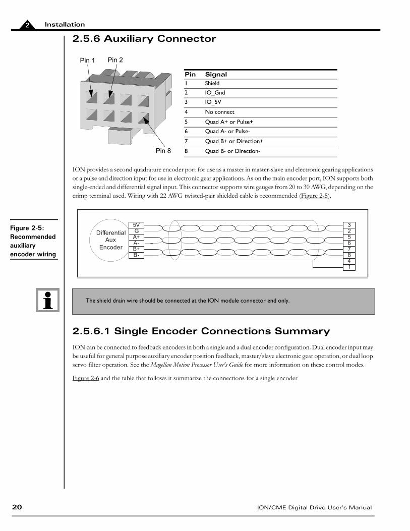
2.5.6 Auxiliary Connector
ION provides a second quadrature encoder port for use as a master in master-slave and electronic gearing applications or a pulse and direction input for use in electronic gear applications. As on the main encoder port, ION supports both single-ended and differential signal input. This connector supports wire gauges from 20 to 30 AWG, depending on the crimp terminal used. Wiring with 22 AWG twisted-pair shielded cable is recommended (Figure 2-5).
2.5.6.1 Single Encoder Connections Summary
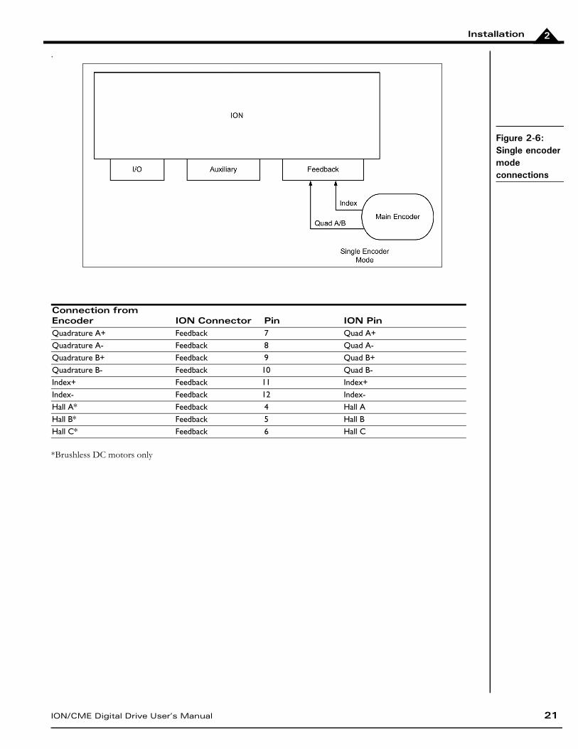
ION can be connected to feedback encoders in both a single and a dual encoder configuration. Dual encoder input may be useful for general purpose auxiliary encoder position feedback, master/slave electronic gear operation, or dual loop servo filter operation. See the Magellan Motion Processor User's Guide for more information on these control modes.
Figure 2-6 and the table that follows it summarize the connections for a single encoder
Pin Signal1 Shield
2 IO_Gnd
3 IO_5V
4 No connect
5 Quad A+ or Pulse+
6 Quad A- or Pulse-
7 Quad B+ or Direction+
8 Quad B- or Direction-
The shield drain wire should be connected at the ION module connector end only.
Pin 1 Pin 2
Pin 8
Figure 2-5: Recommended auxiliary encoder wiring
Differential
Aux
Encoder
32567841
5VGA+A-B+B-
Installation
ION/CME Digital Drive User’s Manual 21
2
.
*Brushless DC motors only
Connection from Encoder ION Connector Pin ION PinQuadrature A+ Feedback 7 Quad A+Quadrature A- Feedback 8 Quad A-Quadrature B+ Feedback 9 Quad B+Quadrature B- Feedback 10 Quad B-Index+ Feedback 11 Index+Index- Feedback 12 Index-Hall A* Feedback 4 Hall AHall B* Feedback 5 Hall BHall C* Feedback 6 Hall C
Figure 2-6: Single encoder mode connections
Installation
22 ION/CME Digital Drive User’s Manual
2
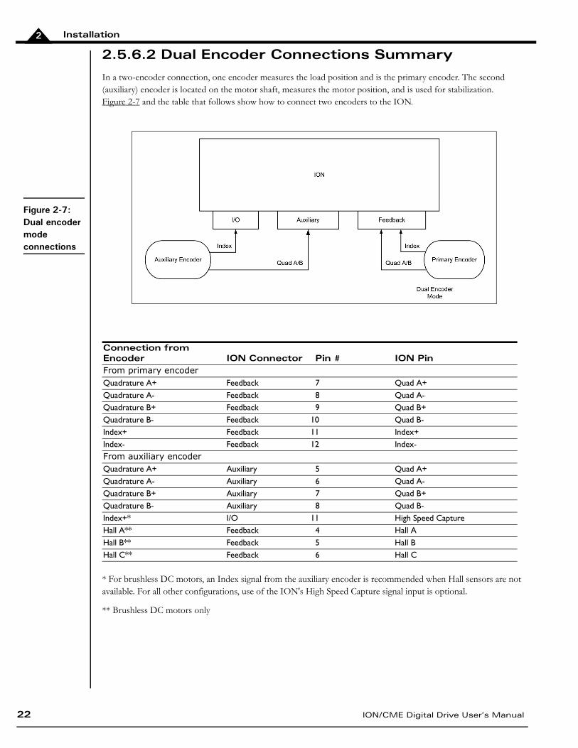
2.5.6.2 Dual Encoder Connections Summary
In a two-encoder connection, one encoder measures the load position and is the primary encoder. The second (auxiliary) encoder is located on the motor shaft, measures the motor position, and is used for stabilization. Figure 2-7 and the table that follows show how to connect two encoders to the ION.
* For brushless DC motors, an Index signal from the auxiliary encoder is recommended when Hall sensors are not available. For all other configurations, use of the ION's High Speed Capture signal input is optional.
** Brushless DC motors only
Connection from Encoder
ION Connector Pin # ION Pin
From primary encoderQuadrature A+ Feedback 7 Quad A+Quadrature A- Feedback 8 Quad A-Quadrature B+ Feedback 9 Quad B+Quadrature B- Feedback 10 Quad B-Index+ Feedback 11 Index+Index- Feedback 12 Index-From auxiliary encoderQuadrature A+ Auxiliary 5 Quad A+Quadrature A- Auxiliary 6 Quad A-Quadrature B+ Auxiliary 7 Quad B+Quadrature B- Auxiliary 8 Quad B-Index+* I/O 11 High Speed CaptureHall A** Feedback 4 Hall AHall B** Feedback 5 Hall BHall C** Feedback 6 Hall C
Figure 2-7: Dual encoder mode connections
Installation
ION/CME Digital Drive User’s Manual 23
2
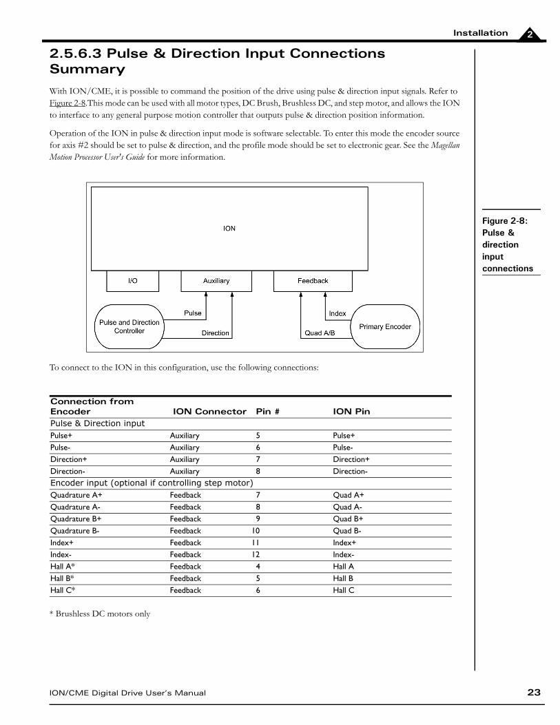
2.5.6.3 Pulse & Direction Input Connections Summary
With ION/CME, it is possible to command the position of the drive using pulse & direction input signals. Refer to Figure 2-8.This mode can be used with all motor types, DC Brush, Brushless DC, and step motor, and allows the ION to interface to any general purpose motion controller that outputs pulse & direction position information.
Operation of the ION in pulse & direction input mode is software selectable. To enter this mode the encoder source for axis #2 should be set to pulse & direction, and the profile mode should be set to electronic gear. See the Magellan Motion Processor User's Guide for more information.
To connect to the ION in this configuration, use the following connections:
* Brushless DC motors only
Connection from Encoder ION Connector Pin # ION PinPulse & Direction inputPulse+ Auxiliary 5 Pulse+Pulse- Auxiliary 6 Pulse-Direction+ Auxiliary 7 Direction+Direction- Auxiliary 8 Direction-Encoder input (optional if controlling step motor)Quadrature A+ Feedback 7 Quad A+Quadrature A- Feedback 8 Quad A-Quadrature B+ Feedback 9 Quad B+Quadrature B- Feedback 10 Quad B-Index+ Feedback 11 Index+Index- Feedback 12 Index-Hall A* Feedback 4 Hall AHall B* Feedback 5 Hall BHall C* Feedback 6 Hall C
Figure 2-8: Pulse & direction input connections
Installation
24 ION/CME Digital Drive User’s Manual
2
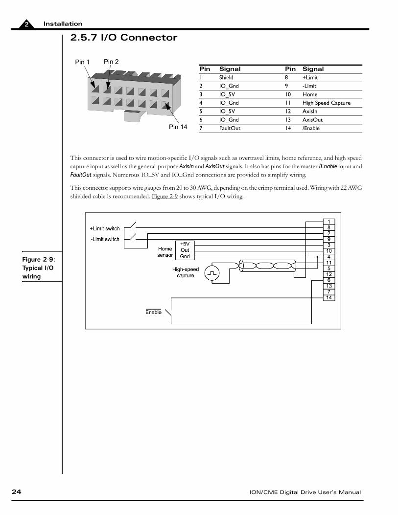
2.5.7 I/O Connector
This connector is used to wire motion-specific I/O signals such as overtravel limits, home reference, and high speed capture input as well as the general-purpose AxisIn and AxisOut signals. It also has pins for the master /Enable input and FaultOut signals. Numerous IO_5V and IO_Gnd connections are provided to simplify wiring.
This connector supports wire gauges from 20 to 30 AWG, depending on the crimp terminal used. Wiring with 22 AWG shielded cable is recommended. Figure 2-9 shows typical I/O wiring.
Pin Signal Pin Signal1 Shield 8 +Limit2 IO_Gnd 9 -Limit3 IO_5V 10 Home4 IO_Gnd 11 High Speed Capture5 IO_5V 12 AxisIn6 IO_Gnd 13 AxisOut7 FaultOut 14 /Enable
Pin 1 Pin 2
Pin 14
Figure 2-9: Typical I/O wiring
Installation
ION/CME Digital Drive User’s Manual 25
2
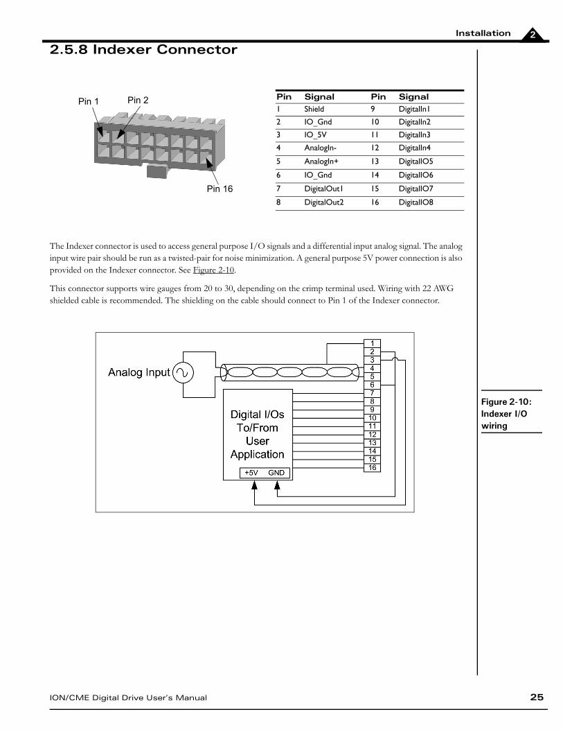
2.5.8 Indexer Connector
The Indexer connector is used to access general purpose I/O signals and a differential input analog signal. The analog input wire pair should be run as a twisted-pair for noise minimization. A general purpose 5V power connection is also provided on the Indexer connector. See Figure 2-10.
This connector supports wire gauges from 20 to 30, depending on the crimp terminal used. Wiring with 22 AWG shielded cable is recommended. The shielding on the cable should connect to Pin 1 of the Indexer connector.
Pin Signal Pin Signal1 Shield 9 DigitalIn1
2 IO_Gnd 10 DigitalIn2
3 IO_5V 11 DigitalIn3
4 AnalogIn- 12 DigitalIn4
5 AnalogIn+ 13 DigitalIO5
6 IO_Gnd 14 DigitalIO6
7 DigitalOut1 15 DigitalIO7
8 DigitalOut2 16 DigitalIO8
Figure 2-10: Indexer I/O wiring
Pin 1 Pin 2
Pin 16
Installation
26 ION/CME Digital Drive User’s Manual
2
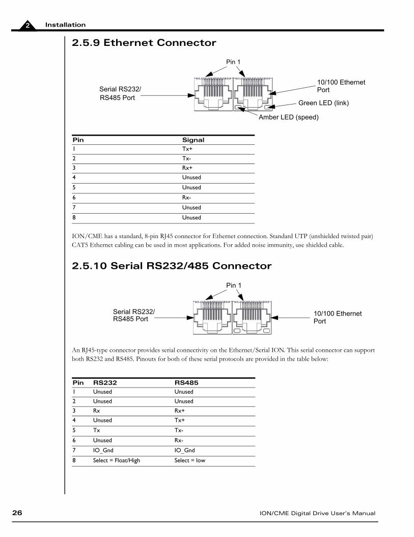
2.5.9 Ethernet Connector
ION/CME has a standard, 8-pin RJ45 connector for Ethernet connection. Standard UTP (unshielded twisted pair) CAT5 Ethernet cabling can be used in most applications. For added noise immunity, use shielded cable.
2.5.10 Serial RS232/485 Connector
An RJ45-type connector provides serial connectivity on the Ethernet/Serial ION. This serial connector can support both RS232 and RS485. Pinouts for both of these serial protocols are provided in the table below:
Pin Signal1 Tx+
2 Tx-
3 Rx+
4 Unused
5 Unused
6 Rx-
7 Unused
8 Unused
Pin RS232 RS4851 Unused Unused
2 Unused Unused
3 Rx Rx+
4 Unused Tx+
5 Tx Tx-
6 Unused Rx-
7 IO_Gnd IO_Gnd
8 Select = Float/High Select = low
Serial RS232/RS485 Port
10/100 EthernetPort
Pin 1
Green LED (link)
Amber LED (speed)
Serial RS232/RS485 Port
10/100 EthernetPort
Pin 1
Installation
ION/CME Digital Drive User’s Manual 27
2
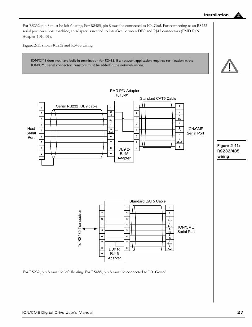
For RS232, pin 8 must be left floating. For RS485, pin 8 must be connected to IO_Gnd. For connecting to an RS232 serial port on a host machine, an adapter is needed to interface between DB9 and RJ45 connectors (PMD P/N Adapter-1010-01).
Figure 2-11 shows RS232 and RS485 wiring.
For RS232, pin 8 must be left floating. For RS485, pin 8 must be connected to IO_Gound.
ION/CME does not have built-in termination for RS485. If a network application requires termination at the ION/CME serial connector, resistors must be added in the network wiring.
Figure 2-11: RS232/485 wiring
Installation
28 ION/CME Digital Drive User’s Manual
2
2.6 Software Installation
Each ION/CME developer’s kit provides several major software packages for motion system development:
Pro-Motion, an interactive Windows-based exerciser and software development tool.
C-Motion, a C-language library that allows the developer to create motion applications using the C pro-gramming language.
C-Motion Engine Development Tools, a set of development resources that allows the developer to create, download, and monitor programs loaded in the ION/CME C-Motion Engine.
Additional information on each of these software packages is provided as follows:
Locate the Pro-Motion CD and install the Pro-Motion application on the host computer, following the instructions in the Pro-Motion User’s Guide. This software will configure the module and fully exercise the features of the ION/CME Digital Drive.
PDF versions of this manual, the Magellan Motion Processor User’s Guide, and the Magellan Motion Processor Programmer’s Command Reference can be found on the CD included with the ION/CME developer’s kit.
Adobe Acrobat Reader is required for viewing these files. If the Adobe Acrobat Reader is not installed on your computer, you may download it at no cost from http://www.adobe.com.
2.7 Communications Configuration
Depending on the communications port you plan to use with your ION, there may be some configuration steps required to communicate correctly between the host computer and the ION module.
2.7.1 Serial Communications
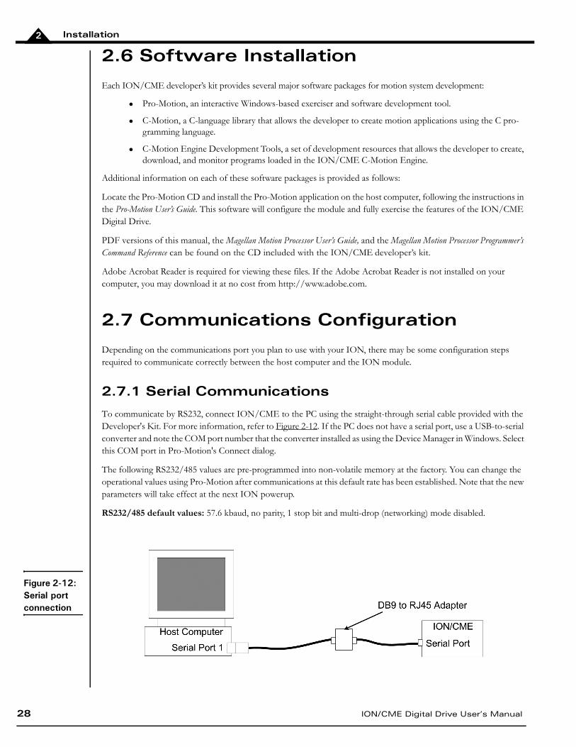
To communicate by RS232, connect ION/CME to the PC using the straight-through serial cable provided with the Developer's Kit. For more information, refer to Figure 2-12. If the PC does not have a serial port, use a USB-to-serial converter and note the COM port number that the converter installed as using the Device Manager in Windows. Select this COM port in Pro-Motion's Connect dialog.
The following RS232/485 values are pre-programmed into non-volatile memory at the factory. You can change the operational values using Pro-Motion after communications at this default rate has been established. Note that the new parameters will take effect at the next ION powerup.
RS232/485 default values: 57.6 kbaud, no parity, 1 stop bit and multi-drop (networking) mode disabled.
Figure 2-12: Serial port connection
Installation
ION/CME Digital Drive User’s Manual 29
2
2.7.2 Ethernet Communications
The ION/CME Ethernet port supports standard 10/100 Ethernet connectivity.
To communicate by Ethernet, a setup procedure must be executed which first uses the serial port to communicate with the ION/CME and configure the Ethernet port for subsequent communications.
To accomplish this, use the DK-provided serial and Ethernet cables and connect the ION/CME to your PC as shown in Figure 2-12. If your computer does not have a dedicated serial port, use a standard USB-to-serial converter.
The Ethernet connection will not be made until serial communications are established. See Section 2.10.2, Changing the Ethernet Parameters of the ION for detailed instructions on when to physically make the Ethernet connection. When Ethernet is ready to connect, use PMD’s Cable-RJ45-02-R, and plug one end of the connector into the ION/CME Ethernet port, and the other end into a free Ethernet port on your network.
2.8 Applying Power
Upon first time power up, ION is in a reset condition. In this condition, no motor output will be applied and the motor will remain stationary. If the motor does move or jump, remove power from the module and re-check the wiring. If anomalous behavior is still observed, call PMD for application assistance. Complete PMD contact information is listed on the final page of this manual.
First-time communication with an ION cannot be accomplished using RS485 half-duplex. To configure an ION for RS485 half-duplex (multi-drop), use either RS232 or RS485 (point-to-point).
Changing the state of the Select pin on the fly is not recommended. Doing so will change the hardware configuration without changing the active set of communication parameters and will most likely result in loss of communications.
Do not apply power to the ION module until the motor and system wiring is complete and the ION module and motor are securely mounted. It is best to leave the motor disconnected from its load until after power is applied for the first time and correct operation is verified. The customer must not attempt to service or rewire an ION drive without first shutting down the drive and disconnecting it from its power source. Failure to follow this warn-ing may result in fire, bodily harm, or damage to the product.
Installation
30 ION/CME Digital Drive User’s Manual
2
2.9 Status LEDs
ION has two bi-color LEDs to indicate the basic operational status of the module and the communications link. The location of these LEDs is shown in Figure 2-1.
2.9.1 Module Status LED
Upon powerup or reset, the module Status LED should either be solid green or blinking green, depending on the state of the /Enable input. If enabled, the LED will be solid green.
A Status LED of any other color indicates a fault or unusual condition that must be rectified before going further. See Section 2.10.2, Changing the Ethernet Parameters of the ION for complete information on ION Operational and Fault modes and the resulting color and blink rate of the Status LED.
2.9.2 Communications Status LED
The Comm Status LED indicates successful packets by blinking green and invalid packets or commands returning an error status by blinking red. A serious fault in the communications port is indicated with solid red. If the LED is solid red, check the cabling and then try cycling power and reconfiguring the communications configuration.
Note that this LED will not blink until communications occur. Therefore, the LED may not blink until further steps in the setup procedure occur.
The /Enable input is active low.
Installation
ION/CME Digital Drive User’s Manual 31
2
2.10 First-Time System Verification
The first time system verification procedure summarized below has two overall goals. The first is to connect the ION with the PC so that they are communicating properly, and the second is to initialize the axis and bring it under stable control capable of making trajectory moves. While there are many additional capabilities that Pro-Motion and ION can provide, these steps will create a foundation for further, successful exploration and development.
Here is a summary of the steps used during first-time system verification. Each of these steps is described below in a separate manual section.
1 Initiate Pro-Motion and establish communication between the PC and the ION. For Serial communica-tions, this is as simple as connecting the ION and running Pro-Motion. For Ethernet communications, this involves a few additional steps as detailed below.
2 Run Pro-Motion’s Axis wizard for each axis of your system to initialize parameters such as encoder direction and safe servo parameters (if you are using a servo motor).
3 Execute a simple trajectory profile on each axis demonstrating that it is operating correctly and under stable control.
During this first-time system setup you may find it useful to refer to other PMD manuals including the Pro-Motion User’s Guide for complete information on the Pro-Motion application. You may also want to refer to the Magellan Motion Processor User’s Guide to familiarize yourself with operation of the Magellan Motion Processor, which lies at the heart of all ION Digital Drives.
2.10.1 Establishing Communications
To establish communications:
1 Make sure the ION is powered and connected to the PC.
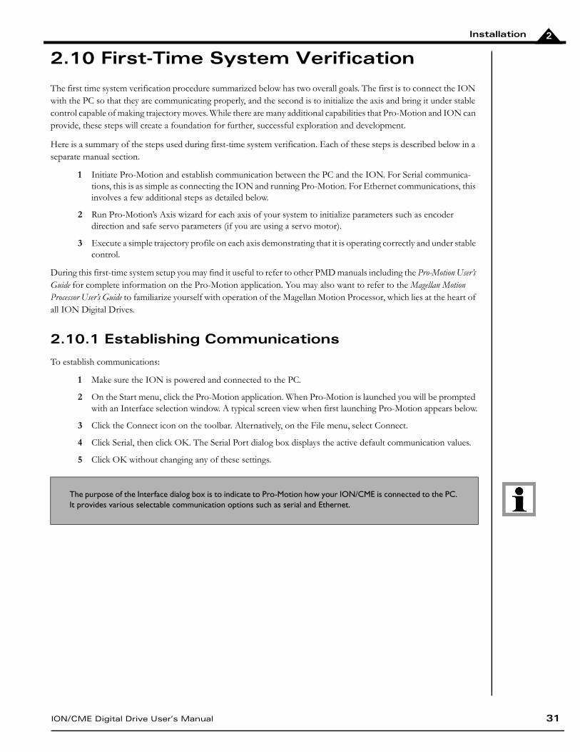
2 On the Start menu, click the Pro-Motion application. When Pro-Motion is launched you will be prompted with an Interface selection window. A typical screen view when first launching Pro-Motion appears below.
3 Click the Connect icon on the toolbar. Alternatively, on the File menu, select Connect.
4 Click Serial, then click OK. The Serial Port dialog box displays the active default communication values.
5 Click OK without changing any of these settings.
The purpose of the Interface dialog box is to indicate to Pro-Motion how your ION/CME is connected to the PC. It provides various selectable communication options such as serial and Ethernet.
Installation
32 ION/CME Digital Drive User’s Manual
2
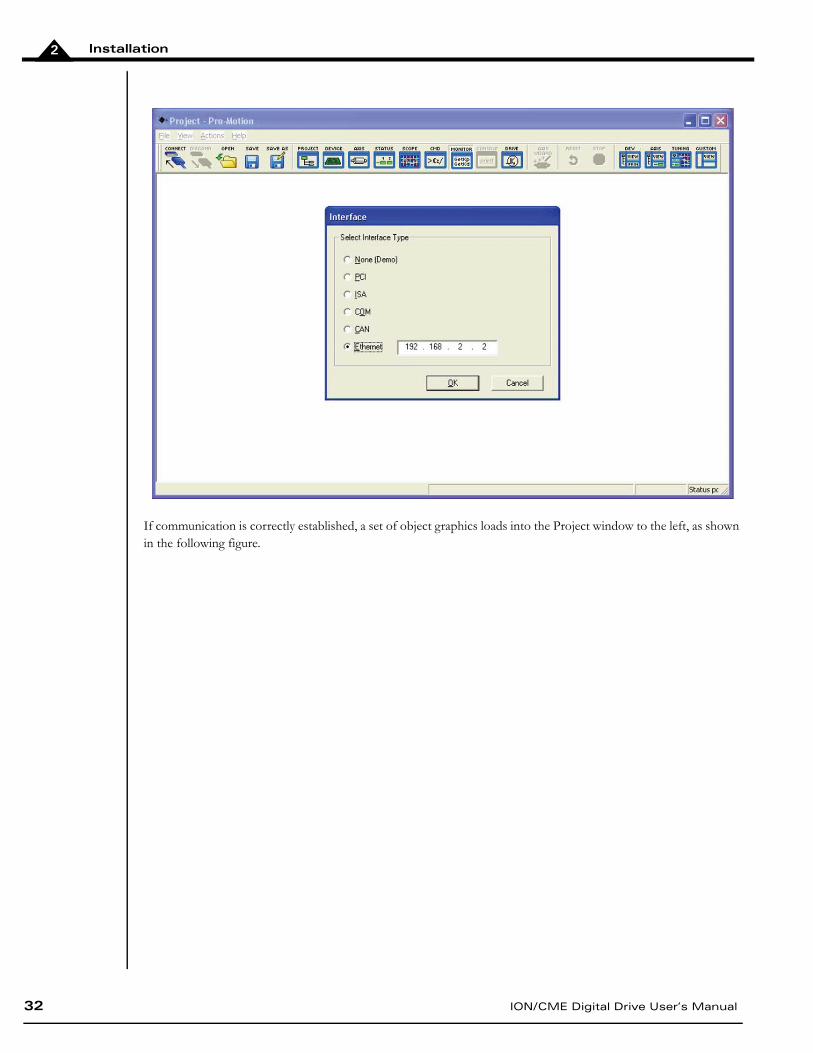
If communication is correctly established, a set of object graphics loads into the Project window to the left, as shown in the following figure.
Installation
ION/CME Digital Drive User’s Manual 33
2
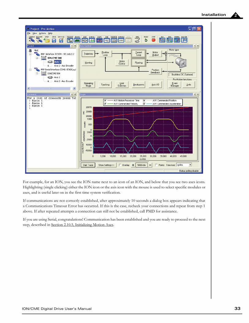
For example, for an ION, you see the ION name next to an icon of an ION, and below that you see two axes icons. Highlighting (single clicking) either the ION icon or the axis icon with the mouse is used to select specific modules or axes, and is useful later on in the first time system verification.
If communications are not correctly established, after approximately 10 seconds a dialog box appears indicating that a Communications Timeout Error has occurred. If this is the case, recheck your connections and repeat from step 1 above. If after repeated attempts a connection can still not be established, call PMD for assistance.
If you are using Serial, congratulations! Communication has been established and you are ready to proceed to the next step, described in Section 2.10.5, Initializing Motion Axes.
Installation
34 ION/CME Digital Drive User’s Manual
2
2.10.2 Changing the Ethernet Parameters of the ION
If you are using Ethernet communications, the next step is to change the Ethernet parameters as follows:
1 With serial communications functioning properly, click the Device toolbar button. The Device window appears.
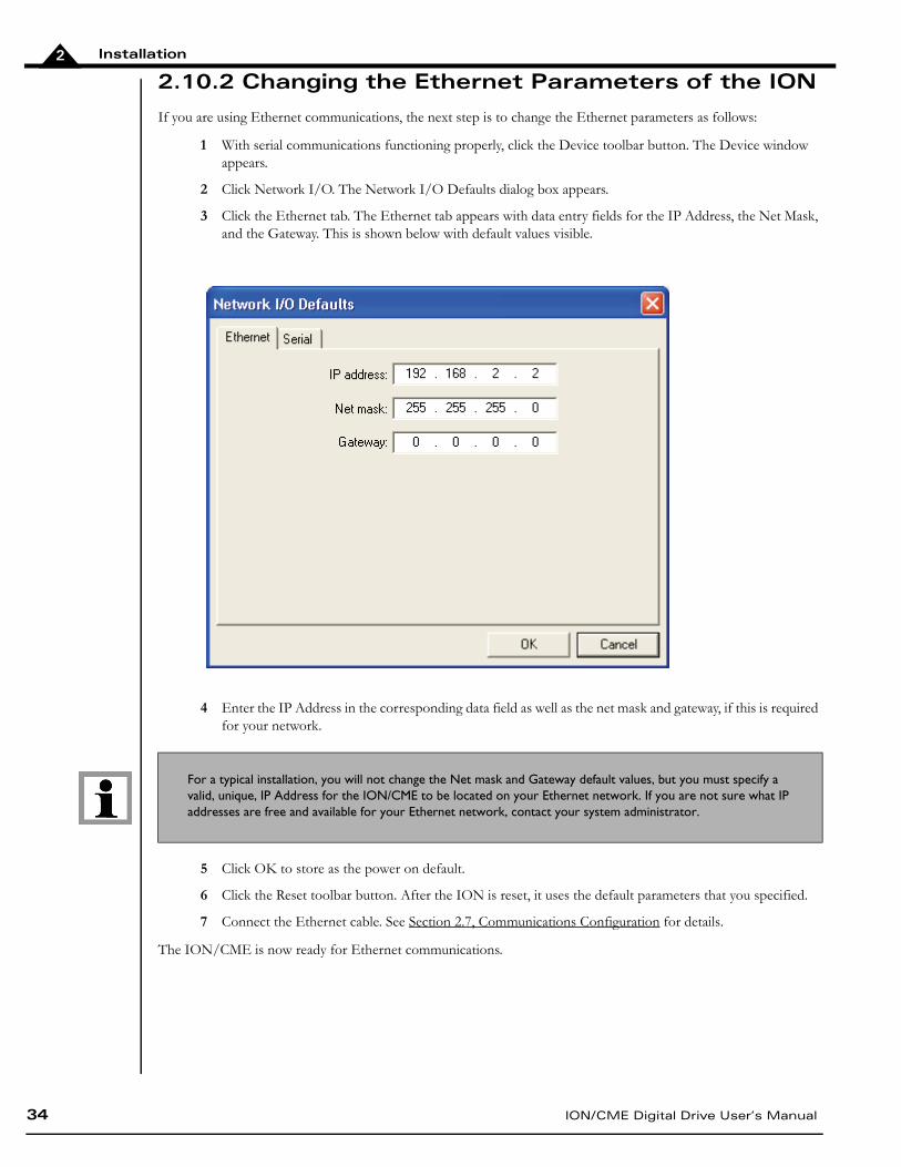
2 Click Network I/O. The Network I/O Defaults dialog box appears.
3 Click the Ethernet tab. The Ethernet tab appears with data entry fields for the IP Address, the Net Mask, and the Gateway. This is shown below with default values visible.
4 Enter the IP Address in the corresponding data field as well as the net mask and gateway, if this is required for your network.
5 Click OK to store as the power on default.
6 Click the Reset toolbar button. After the ION is reset, it uses the default parameters that you specified.
7 Connect the Ethernet cable. See Section 2.7, Communications Configuration for details.
The ION/CME is now ready for Ethernet communications.
For a typical installation, you will not change the Net mask and Gateway default values, but you must specify a valid, unique, IP Address for the ION/CME to be located on your Ethernet network. If you are not sure what IP addresses are free and available for your Ethernet network, contact your system administrator.
Installation
ION/CME Digital Drive User’s Manual 35
2
2.10.3 Establishing Ethernet Communications
The ION's IP Address has now been set, but Pro-Motion does not know what IP address it should use for Ethernet communications to the ION.
To establish Ethernet communications:
1 Click the Connect toolbar button.
2 Select Ethernet, and then click OK.
3 Enter the same IP Address as was specified for Ethernet ION.
4 When complete, click OK.
If Ethernet communication is successful, an additional set of graphical icons representing your ION and axis will be loaded into the Project window.
If communication is not successful, after about 30 seconds, a Communications Timeout Error dialog box appears. If this happens, recheck your connections, and retry to establish Ethernet communications. See step 1 in Section 2.10.2, Changing the Ethernet Parameters of the ION for details.
When Ethernet communications are functioning properly, the final step is to disable serial communications.
2.10.4 Disconnecting Serial Communications
To disconnect serial communications:
1 Select the serial link version of the ION in the Project window.
2 Click the Disconnect toolbar button. A dialog box appears asking if you are sure you want to disconnect.
3 Click OK. You will notice that the serial ION icon and axes graphical icons in the Project box disappear, leaving only the Ethernet link icons for the ION and axis.
Congratulations! Ethernet communication is now up and running. You are ready to execute all Pro-Motion functions via Ethernet.
Multiple Pro-Motion users can connect to the same Ethernet ION. There are various situations where this may be useful. For example, one PC can function as a 'monitoring station' for a particular ION while another PC pro-vides commands to that same unit. Be aware, however, that two or more users sending motion commands to the same motion controller can cause unexpected motion, and should be avoided.
When connecting your ION for use on an Ethernet network, be sure that the IP address provided for the ION does not conflict with the addresses of other users on the network. See Section 2.10.2, Changing the Ethernet Parameters of the ION for a description of changing the IP address.
Installation
36 ION/CME Digital Drive User’s Manual
2
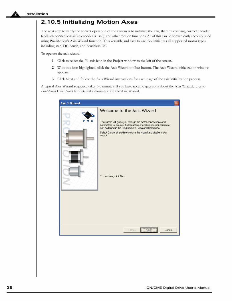
2.10.5 Initializing Motion Axes
The next step to verify the correct operation of the system is to initialize the axis, thereby verifying correct encoder feedback connections (if an encoder is used), and other motion functions. All of this can be conveniently accomplished using Pro-Motion’s Axis Wizard function. This versatile and easy to use tool initializes all supported motor types including step, DC Brush, and Brushless DC.
To operate the axis wizard:
1 Click to select the #1 axis icon in the Project window to the left of the screen.
2 With this icon highlighted, click the Axis Wizard toolbar button. The Axis Wizard initialization window appears.
3 Click Next and follow the Axis Wizard instructions for each page of the axis initialization process.
A typical Axis Wizard sequence takes 3-5 minutes. If you have specific questions about the Axis Wizard, refer to Pro-Motion User’s Guide for detailed information on the Axis Wizard.
Installation
ION/CME Digital Drive User’s Manual 37
2
Upon a normal completion of the Axis Wizard, the axis will be ready to make a controlled move. Depending on the signals connected, this may also mean that limit switches, and other hardware connections are functioning properly.
The most common reasons for the Axis Wizard to not complete normally are an inability to auto-tune the servo motor, or problems determining the correct commutation sequence for Brushless DC motors when commutated by the Magellan Motion Processor. Should this happen, it is possible to perform a manual tuning or commutation setup if desired. Refer to the Pro-Motion User’s Guide for more information, or call PMD for technical assistance.
2.10.6 Performing a Simple Trajectory Move
The last step in first time system verification is to perform a simple move for each axis.
To perform a simple move:
1 In the Project Window, select the motion axis that you would like to move by clicking the corresponding icon.
2 Click the Axis view button on the far right of the toolbar. Alternatively, click Axis View on the Axis menu. Your screen organization changes to give easy access to windows that are used while exercising the motion axes.
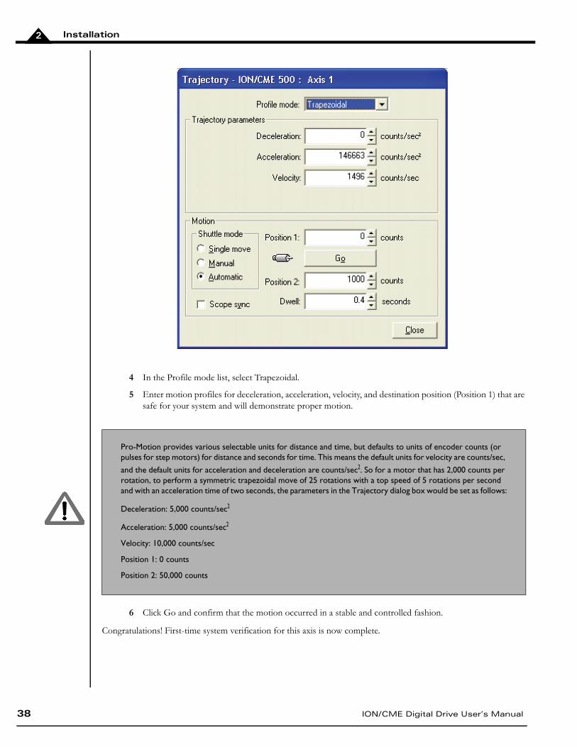
3 Click the Trajectory button in the Axis Control window. The Trajectory dialog box appears.
The Axis Wizard auto tuning routine, which is used with servo motors, is designed to provide stable, but not optimal, parameters for motion. Pro-Motion provides a wealth of functions including a high speed hardware trace oscilloscope that can assist you in determining optimal servo parameters. Values provided by the axis wizard dur-ing auto tuning may or may not be safe for your system, and it is up to the user to determine if and when they should be used.
Installation
38 ION/CME Digital Drive User’s Manual
2
4 In the Profile mode list, select Trapezoidal.
5 Enter motion profiles for deceleration, acceleration, velocity, and destination position (Position 1) that are safe for your system and will demonstrate proper motion.
6 Click Go and confirm that the motion occurred in a stable and controlled fashion.
Congratulations! First-time system verification for this axis is now complete.
Pro-Motion provides various selectable units for distance and time, but defaults to units of encoder counts (or pulses for step motors) for distance and seconds for time. This means the default units for velocity are counts/sec,
and the default units for acceleration and deceleration are counts/sec2. So for a motor that has 2,000 counts per rotation, to perform a symmetric trapezoidal move of 25 rotations with a top speed of 5 rotations per second and with an acceleration time of two seconds, the parameters in the Trajectory dialog box would be set as follows:
Deceleration: 5,000 counts/sec2
Acceleration: 5,000 counts/sec2
Velocity: 10,000 counts/sec
Position 1: 0 counts
Position 2: 50,000 counts
ION/CME Digital Drive User’s Manual 39
33. OperationIn This ChapterION/CME Block DiagramCommunication PortPWM Power StageDC BusTrace Buffer Operational and Fault Modes
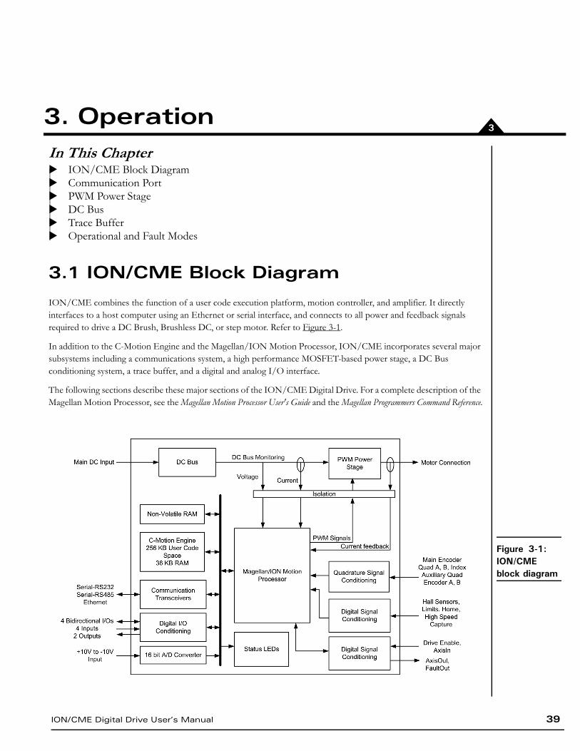
3.1 ION/CME Block Diagram
ION/CME combines the function of a user code execution platform, motion controller, and amplifier. It directly interfaces to a host computer using an Ethernet or serial interface, and connects to all power and feedback signals required to drive a DC Brush, Brushless DC, or step motor. Refer to Figure 3-1.
In addition to the C-Motion Engine and the Magellan/ION Motion Processor, ION/CME incorporates several major subsystems including a communications system, a high performance MOSFET-based power stage, a DC Bus conditioning system, a trace buffer, and a digital and analog I/O interface.
The following sections describe these major sections of the ION/CME Digital Drive. For a complete description of the Magellan Motion Processor, see the Magellan Motion Processor User's Guide and the Magellan Programmers Command Reference.
Figure 3-1: ION/CME block diagram
Operation
40 ION/CME Digital Drive User’s Manual
3
3.2 Communication Port
3.2.1 Ethernet
The ION/CME features a standard 10/100Mbps Ethernet interface. An RJ45 connector with link lights is provided for the connection.
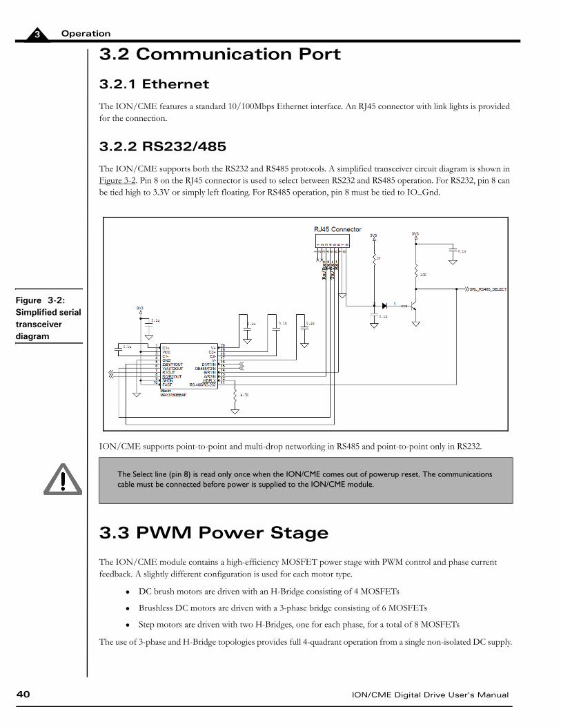
3.2.2 RS232/485
The ION/CME supports both the RS232 and RS485 protocols. A simplified transceiver circuit diagram is shown in Figure 3-2. Pin 8 on the RJ45 connector is used to select between RS232 and RS485 operation. For RS232, pin 8 can be tied high to 3.3V or simply left floating. For RS485 operation, pin 8 must be tied to IO_Gnd.
ION/CME supports point-to-point and multi-drop networking in RS485 and point-to-point only in RS232.
3.3 PWM Power Stage
The ION/CME module contains a high-efficiency MOSFET power stage with PWM control and phase current feedback. A slightly different configuration is used for each motor type.
DC brush motors are driven with an H-Bridge consisting of 4 MOSFETs
Brushless DC motors are driven with a 3-phase bridge consisting of 6 MOSFETs
Step motors are driven with two H-Bridges, one for each phase, for a total of 8 MOSFETs
The use of 3-phase and H-Bridge topologies provides full 4-quadrant operation from a single non-isolated DC supply.
The Select line (pin 8) is read only once when the ION/CME comes out of powerup reset. The communications cable must be connected before power is supplied to the ION/CME module.
Figure 3-2: Simplified serial transceiver diagram
Operation
ION/CME Digital Drive User’s Manual 41
3
ION/CME uses an advanced PWM switching scheme that minimizes the ripple current on the motor windings while maximizing the current loop performance. The PWM frequency is selectable between 20 kHz and 40 kHz to cover a broad range of motor inductance. The fundamental frequency of the ripple current is at twice the PWM frequency and well out of the audible range in all cases.
Two channels of phase current feedback are used for brushless DC and step motor current loops. In the brushless DC version, the third phase is simply calculated as the negated sum of the other two phase currents. For DC brush motors, only one phase current feedback is used.
By monitoring the DC bus voltage, the DC bus current, and the output phase currents, the ION/CME Digital Drive’s output stage is fully protected from overcurrent, overvoltage, and undervoltage faults and line-to-line, line-to-power supply, and line-to-earth/case ground short circuits. The Magellan Motion Processor also implements I2t current foldback and automatic holding current reduction for step motors.
3.3.1 I2t Current Foldback Protection
ION/CME uses the current feedback to implement I2t current limiting. This feature protects the drive by controlling its ability to operate above continuous current ratings. This protection feature is active in all operating modes.
When the current loop is enabled and the I2t energy limit is exceeded, ION/CME will automatically fold back the phase currents to a user programmable continuous current limit value. Alternatively, ION/CME can be configured to fault and disable the output stage when the I2t energy limit is exceeded.
When the current loop is disabled (ION/CME is operating in voltage control mode only) and the I2t energy limit is exceeded, ION/CME will always fault and disable the output stage.
3.3.2 Overtemperature Protection
ION/CME uses digital temperature sensors to monitor the operating temperature of the output stage power MOSFETs. The motion processor communicates with the sensors over the built-in SPI bus. If an overtemperature condition is detected, ION/CME shuts down the output stage, indicates the fault with the Module Status LED and optionally activates FaultOut.
The overtemperature threshold is user-settable to any value below the maximum-rated operating temperature of the output stage. See Section 7.4, ION/CME Protection Circuits, for the programmable overtemperature range and the Magellan Motion Processor Programmer’s Command Reference for more information on setting the temperature threshold.
Refer to the Magellan Motion Processor User’s Guide and the Magellan Motion Processor Programmer’s Command Reference for more information on Operating Modes and on setting up these current foldback parameters.
3.3.3 Power Stage Scaling Parameters
To correctly control various ION/CME features via the Magellan Motion Processor it is helpful to know certain drive-specific scale factors. The following tables summarize these values.
Operation
42 ION/CME Digital Drive User’s Manual
3
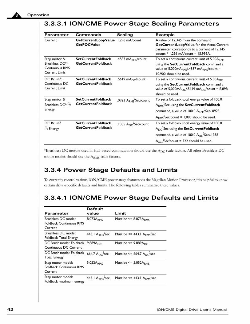
3.3.3.1 ION/CME Power Stage Scaling Parameters
*Brushless DC motors used in Hall-based commutation should use the ADC scale factors. All other Brushless DC
motor modes should use the ARMS scale factors.
3.3.4 Power Stage Defaults and Limits
To correctly control various ION/CME power stage features via the Magellan Motion Processor, it is helpful to know certain drive-specific defaults and limits. The following tables summarize these values.
3.3.4.1 ION/CME Power Stage Defaults and Limits
Parameter Commands Scaling ExampleCurrent GetCurrentLoopValue
GetFOCValue1.296 mA/count A value of 12,345 from the command
GetCurrentLoopValue for the ActualCurrent parameter corresponds to a current of 12,345 counts * 1.296 mA/count = 15.999A.
Step motor & Brushless DC*: Continuous RMS Current Limit
SetCurrentFoldbackGetCurrentFoldback
.4587 mARMS/count To set a continuous current limit of 5.00ARMS using the SetCurrentFoldback command a value of 5,000mARMS/.4587 mARMS/count = 10,900 should be used.
DC Brush*: Continuous DC Current Limit
SetCurrentFoldbackGetCurrentFoldback
.5619 mADC/count To set a continuous current limit of 5.00ADC using the SetCurrentFoldback command a value of 5,000mADC/.5619 mADC/count = 8,898 should be used.
Step motor &
Brushless DC* I2t Energy
SetCurrentFoldbackGetCurrentFoldback
.0923 ARMS2Sec/count To set a foldback total energy value of 100.0
ARMS2Sec using the SetCurrentFoldback
command, a value of 100.0 ARMS2Sec/.0923
ARMS2Sec/count = 1,083 should be used.
DC Brush*
I2t Energy
SetCurrentFoldbackGetCurrentFoldback
.1385 ADC2Sec/count To set a foldback total energy value of 100.0
ADC2Sec using the SetCurrentFoldback
command, a value of 100.0 ADC2Sec/.1385
Arms2Sec/count = 722 should be used.
ParameterDefault value Limit
Brushless DC model: Foldback Continuous RMS Current
8.073ARMS Must be <= 8.073ARMS
Brushless DC model: Foldback Total Energy
443.1 ARMS2sec Must be <= 443.1 ARMS
2sec
DC Brush model: Foldback Continuous DC Current
9.889ADC Must be <= 9.889ADC
DC Brush model: Foldback Total Energy
664.7 ADC2sec Must be <= 664.7 ADC
2sec
Step motor model: Foldback Continuous RMS Current
5.052ARMS Must be <= 5.052ARMS
Step motor model: Foldback maximum energy
443.1 ARMS2sec Must be <= 443.1 ARMS
2sec
Operation
ION/CME Digital Drive User’s Manual 43
3
For the ION/CME, default values and limits for the Foldback Continuous Current Limit and Foldback Energy Limit are designed to be safe for operation in the drive's highest output mounting option, namely, horizontal to cold plate. See Section 2.4, ION/CME Hardware Configuration and Mounting, for information on ION/CME mounting options.
If the ION/CME drive is being operated at a lower voltage, it may be possible to specify values for Foldback Continuous Current Limit and Foldback Energy Limit that are higher than the default, but lower than or equal to the limit, since the continuous output current rating of the ION/CME drive is higher for lower input voltages. See Section 7.1, ION/CME Drive Ratings, for drive output specifications.
For other mounting configurations, or for use with motors that have lower current and energy limits, it may be useful to set these parameters to values lower than the default values.
3.4 DC Bus
3.4.1 DC Bus Current Monitoring
ION/CME monitors both the positive and negative DC bus current to detect overcurrent conditions including: line-to-line, line-to-power supply, and line-to-case-ground short circuits. Both hard short circuits and excessive current conditions are detected. ION/CME can even detect some “ground fault” conditions caused by a partial winding short circuit between winding and case within a motor.
When an overcurrent condition occurs, the output stage is shut down and the ION/CME module goes into the hard fault state. See Section 3.6.1, Hard Fault State, for a description of this state.
3.4.2 DC Bus Overvoltage and Undervoltage
ION/CME monitors the main DC bus voltage for overvoltage and undervoltage conditions. These thresholds are user-settable within the voltage operating range of the drive.
When the DC bus voltage drops below the undervoltage threshold, ION/CME shuts down the output stage, indicates the fault with the Module Status LED, and optionally activates FaultOut.
There are two ways for the DC bus to exceed the overvoltage threshold:
1 The supplied DC power is too high. There is little the ION/CME module can do about this. ION/CME simply turns off the output stage, indicates the fault with the Module Status LED and optionally activates FaultOut.
2 The motor is decelerating at a rate too high for the DC power supply to absorb the regenerated energy and the DC bus “pumps up.” ION/CME will protect itself by turning off the output stage. It also indicates the fault with the Module Status LED and optionally activates FaultOut.
In either case, the DC bus voltage must then fall below the threshold before the module exits this fault state and can be re-enabled.
It is the responsibility of the user to set the Foldback Continuous Current and Foldback Energy Limit parameters to values that are safe for the specific ION/CME mounting configuration and motor setup being used.
Operation
44 ION/CME Digital Drive User’s Manual
3
3.4.3 IO_5V Monitor
ION/CME features a separate 5V supply for powering external encoders, Hall sensors, and other I/O devices. This supply is monitored to detect overloading or out-of-tolerance operation and if either condition occurs, ION/CME goes into the hard fault state. See Section 3.6.1, Hard Fault State, for a description of this state.
3.4.4 Motion Processor 3.3V Supply Monitor and Reset Circuit
The 3.3V supply for the motion processor automatically forces the processor into the reset state if the supply voltage falls out of regulation.
3.4.5 DC Bus Scaling Parameters
To correctly control ION/CME DC Bus features via the Magellan Motion Processor it is helpful to know the DC Bus scale factor. The following table summarizes this value.
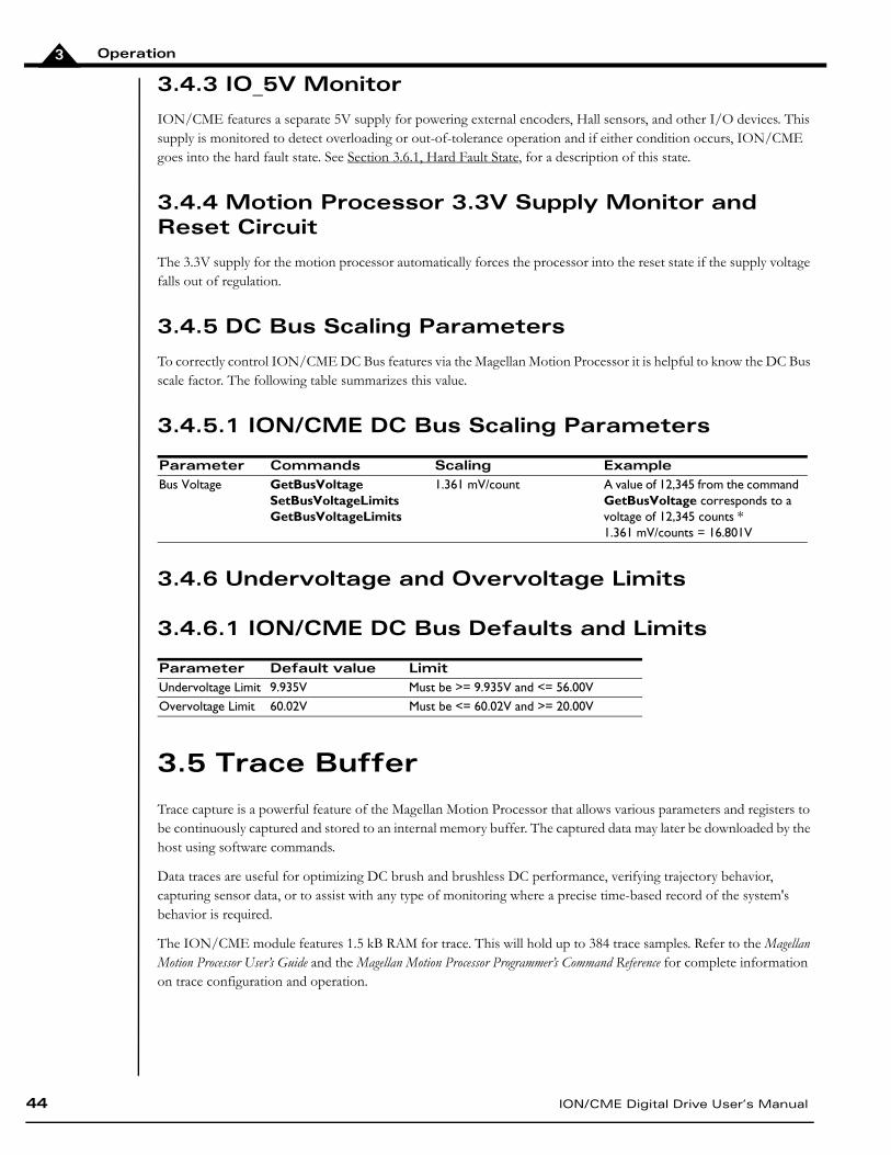
3.4.5.1 ION/CME DC Bus Scaling Parameters
3.4.6 Undervoltage and Overvoltage Limits
3.4.6.1 ION/CME DC Bus Defaults and Limits
3.5 Trace Buffer
Trace capture is a powerful feature of the Magellan Motion Processor that allows various parameters and registers to be continuously captured and stored to an internal memory buffer. The captured data may later be downloaded by the host using software commands.
Data traces are useful for optimizing DC brush and brushless DC performance, verifying trajectory behavior, capturing sensor data, or to assist with any type of monitoring where a precise time-based record of the system's behavior is required.
The ION/CME module features 1.5 kB RAM for trace. This will hold up to 384 trace samples. Refer to the Magellan Motion Processor User’s Guide and the Magellan Motion Processor Programmer’s Command Reference for complete information on trace configuration and operation.
Parameter Commands Scaling ExampleBus Voltage GetBusVoltage
SetBusVoltageLimitsGetBusVoltageLimits
1.361 mV/count A value of 12,345 from the command GetBusVoltage corresponds to a voltage of 12,345 counts *1.361 mV/counts = 16.801V
Parameter Default value LimitUndervoltage Limit 9.935V Must be >= 9.935V and <= 56.00VOvervoltage Limit 60.02V Must be <= 60.02V and >= 20.00V
Operation
ION/CME Digital Drive User’s Manual 45
3
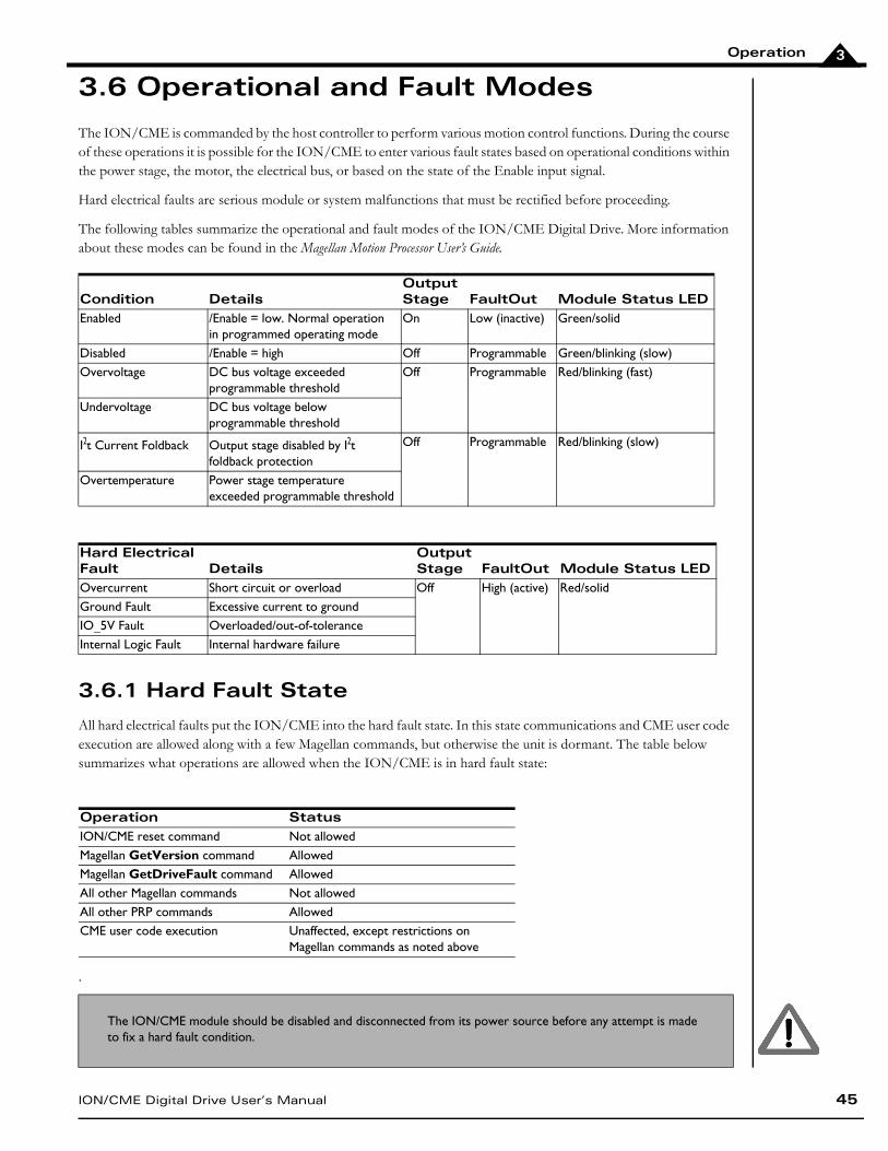
3.6 Operational and Fault Modes
The ION/CME is commanded by the host controller to perform various motion control functions. During the course of these operations it is possible for the ION/CME to enter various fault states based on operational conditions within the power stage, the motor, the electrical bus, or based on the state of the Enable input signal.
Hard electrical faults are serious module or system malfunctions that must be rectified before proceeding.
The following tables summarize the operational and fault modes of the ION/CME Digital Drive. More information about these modes can be found in the Magellan Motion Processor User’s Guide.
3.6.1 Hard Fault State
All hard electrical faults put the ION/CME into the hard fault state. In this state communications and CME user code execution are allowed along with a few Magellan commands, but otherwise the unit is dormant. The table below summarizes what operations are allowed when the ION/CME is in hard fault state:
.
Condition DetailsOutput Stage FaultOut Module Status LED
Enabled /Enable = low. Normal operation in programmed operating mode
On Low (inactive) Green/solid
Disabled /Enable = high Off Programmable Green/blinking (slow)Overvoltage DC bus voltage exceeded
programmable thresholdOff Programmable Red/blinking (fast)
Undervoltage DC bus voltage below programmable threshold
I2t Current Foldback Output stage disabled by I2t foldback protection
Off Programmable Red/blinking (slow)
Overtemperature Power stage temperature exceeded programmable threshold
Hard Electrical Fault Details
Output Stage FaultOut Module Status LED
Overcurrent Short circuit or overload Off High (active) Red/solidGround Fault Excessive current to groundIO_5V Fault Overloaded/out-of-toleranceInternal Logic Fault Internal hardware failure
Operation StatusION/CME reset command Not allowedMagellan GetVersion command AllowedMagellan GetDriveFault command AllowedAll other Magellan commands Not allowedAll other PRP commands AllowedCME user code execution Unaffected, except restrictions on
Magellan commands as noted above
The ION/CME module should be disabled and disconnected from its power source before any attempt is made to fix a hard fault condition.
Operation
46 ION/CME Digital Drive User’s Manual
3
The following sequence should be used to recover from the hard fault state:
1 Unless the failure is clearly caused by external circumstances, the ION/CME module should be disconnect-ed from the serial network, as well as disconnected from all external hardware such as the motor, motor encoder, power supply, etc.
2 With all external hardware disconnected, restore the module power. If the unit is still in the hard fault state as indicated by the red Module Status LED, the drive is likely to have sustained an unrecoverable failure, and should be considered unusable thereafter. A replacement ION/CME module should be used in the appli-cation.
3 If the Module Status LED indicates that a fault is no longer present, the cause can be determined by recon-necting the communications cable, cycling power again, and reading the Drive Fault Status from the ION/CME module. See the Magellan Motion Processor User’s Guide for more information on reading the Drive Fault Status.
4 Once the nature of the fault is known, it must be corrected. It is always the responsibility of the user to main-tain safe operating conditions of the ION/CME module as well as all associated electronics or hardware.
5 With the source of the problem corrected, the ION/CME module can be reinstalled and reconnected. It should now function normally.
ION/CME Digital Drive User’s Manual 47
44. ION/CME ControlIn This ChapterCommunication ProtocolsION/CME Access BasicsMagellan Motion Processor FunctionsGeneral Purpose Digital I/OAnalog InputC-Motion Engine FunctionsCommunications FunctionsION/CME ResetNon-volatile MemorySetting Module DefaultsION/CME Command Summary
4.1 Communication Protocols
ION/CME Digital Drives can be controlled by an external host controller, can be operated internally using application code downloaded into the C-Motion Engine, or can operate both from external and internal control.
The ION/CME Ethernet and serial ports can be used to send standard commands to IONs attached to the network, or can be programmed to implement a custom-designed protocol. This high level of communication flexibility makes the ION/CME an ideal platform for integration into a large variety of control architectures.
The communication protocol that makes all of this possible is called PRP (PMD Resource access Protocol). This manual will introduce some basic aspects of this protocol, but for a complete description of PRP refer to the PMD Resource Access Protocol Programmer’s Reference.
4.1.1 ION/CME Control Notes
When commanding the ION/CME using PMD’s standard command language, most ION/CME users will not concern themselves with the low level details of communication command protocols because they will use the library of C-lan-guage routines provided by PMD.
This library of C-language functions insulates the user from protocol and platform details by providing virtualized C-language interfaces to all supported commands. So, for example, code that is written to control a Magellan located on a serial-connected ION/CME will work just as well when used with an Ethernet-connected ION/CME, or microprocessor-connected Magellan IC on a user-designed motion control card.
ION/CME Control
48 ION/CME Digital Drive User’s Manual
4
4.2 ION/CME Access Basics
Access to the ION/CME from the Ethernet or serial port is provided by a protocol called the PMD Resource access Protocol (PRP). This easy-to-use yet powerful system utilizes actions, resources, and addresses to access the ION/CME’s functions. Various ION/CME functions are organized into resources, and resources process actions sent to them. Actions can send information, request information, or command specific events to occur. Addresses allow access to a specific resource on the unit, or connected to it, via the Ethernet or serial connections.
A basic communication to the ION/CME consists of a 16-bit PRP header and an optional message body. The message body contains data associated with the specified PRP action, but some actions do not require a message body. After a PRP communication is sent to the ION/CME, a return communication is sent by the ION/CME which consists of a PRP header and an optional return message body. The return message body may contain information associated with the requested PRP action, or it may contain error information if there was a problem processing the requested action.
The ION/CME supports five resource types. The Device resource indicates functionality that is addressed to the entire card, the MotionProcessor resource indicates a Magellan Motion Processor, the CMotionEngine resource indicates the C-Motion Engine, the Memory resource indicates a type of memory and the Peripheral resource indicates a communications connection.
There are ten different PRP actions including Command, which is used to send commands to resources such as the Magellan Motion Processor, Send and Receive, which are used to communicate using the Ethernet and serial ports, and Set and Get, which are used to load or read parameters.
The PMD Resource Access Protocol Programmer’s Reference describes all of these constructs in more detail. In the subsequent sections of this chapter a summary of the PRP actions that are required to access each ION/CME function are included with the descriptions of the functions themselves.
4.3 Magellan Motion Processor Functions
The Magellan Motion Processor block pictured in Figure 4-1 forms the core of ION/CME. Here is an overview of the functions provided, or managed, by the Magellan Motion Processor on the ION/CME.
• Profile generation
• Pulse & direction signal processing
• Quadrature encoder processing and index capture
• DC brush and brushless DC servo loop closure
• Breakpoint processing
• AxisIn and AxisOut signal processing
• Trace
• Motion error detection, tracking windows, and at-settled indicator
• Limit switches
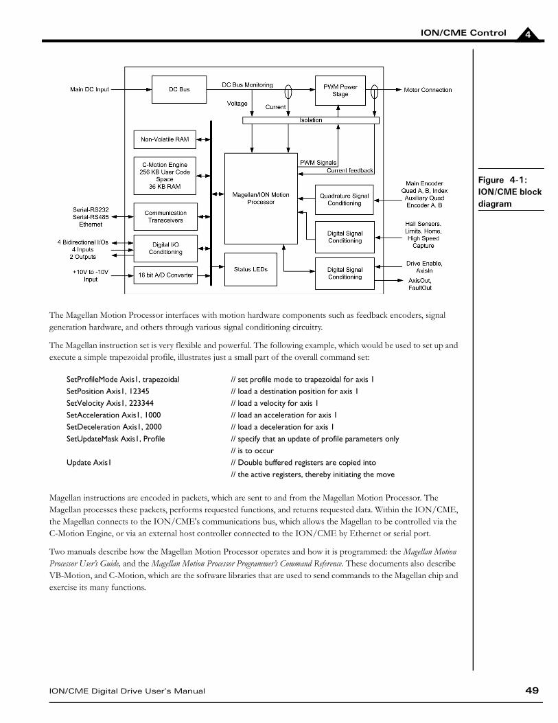
ION/CME Control
ION/CME Digital Drive User’s Manual 49
4
The Magellan Motion Processor interfaces with motion hardware components such as feedback encoders, signal generation hardware, and others through various signal conditioning circuitry.
The Magellan instruction set is very flexible and powerful. The following example, which would be used to set up and execute a simple trapezoidal profile, illustrates just a small part of the overall command set:
Magellan instructions are encoded in packets, which are sent to and from the Magellan Motion Processor. The Magellan processes these packets, performs requested functions, and returns requested data. Within the ION/CME, the Magellan connects to the ION/CME's communications bus, which allows the Magellan to be controlled via the C-Motion Engine, or via an external host controller connected to the ION/CME by Ethernet or serial port.
Two manuals describe how the Magellan Motion Processor operates and how it is programmed: the Magellan Motion Processor User’s Guide, and the Magellan Motion Processor Programmer’s Command Reference. These documents also describe VB-Motion, and C-Motion, which are the software libraries that are used to send commands to the Magellan chip and exercise its many functions.
SetProfileMode Axis1, trapezoidal // set profile mode to trapezoidal for axis 1SetPosition Axis1, 12345 // load a destination position for axis 1SetVelocity Axis1, 223344 // load a velocity for axis 1SetAcceleration Axis1, 1000 // load an acceleration for axis 1SetDeceleration Axis1, 2000 // load a deceleration for axis 1SetUpdateMask Axis1, Profile // specify that an update of profile parameters only
// is to occurUpdate Axis1 // Double buffered registers are copied into
// the active registers, thereby initiating the move
Figure 4-1: ION/CME block diagram
ION/CME Control
50 ION/CME Digital Drive User’s Manual
4
4.3.1 Accessing the Magellan Motion Processor
To send and receive command packets to the Magellan Motion Processor the PRP action Command is used. The Magellan command packet is loaded into the PRP message body, and the return PRP message body contains the return packet provided by the Magellan. A return without error indicates that the command was processed successfully. If an error occurred while the Magellan was processing the command, the message body is loaded with the specific error that occurred. For more information, see the PMD Resource Access Protocol Programmer’s Reference.
In addition to accessing the on-ION/CME Magellan, it is also possible to access Magellan Motion Processors that are connected via the ION/CME’s attached Ethernet networks. An additional PRP action, Open, sent to either the Device or the Peripheral resource, is used to establish a connection to such a motion processor. See the PMD Resource Access Protocol Programmer’s Reference for more information on connecting to motion processors on attached networks.
4.3.1.1 Magellan Reset
Although a reset occurs automatically during power-up, it is sometimes desirable to reset the Magellan Motion Processor explicitly through a user-initiated action. The PRP action Reset, when sent to the MotionProcessor resource, causes a reset of the Magellan Motion Processor. This reset affects the Magellan Motion Processor, and a number of Magellan-controlled signals. Note however that this type of reset is different than a full ION/CME reset initiated via the PRP action Reset, described in Section 2.8, Applying Power,.
After a Magellan reset occurs, some of the ION/CME’s output signals will be driven to known states. These are summarized in the following table:
4.4 General Purpose Digital I/O
In addition to special-purpose digital signals, such as AxisIn, AxisOut, Home, and QuadA which are input to or output from the ION/CME, and which are directly processed by the Magellan Motion Processor, the ION/CME also supports several general-purpose input and output signals through its Indexer connector. There are two outputs, four inputs, four bi-directional I/Os and one 16-bit ±10V analog input. These signals provide a convenient way of accessing additional application-specific general purpose digital I/O.
The I/Os are accessed via the CME peripheral functions: Open Peripheral Parallel, Peripheral Read and Peripheral Write.
Signal Name StateAxisOut 1FaultOut 0
The general purpose digital inputs are TTL-compatible with a typical input range of 0-5.5V. The inputs are overvoltage protected to 30V.
The general purpose digital outputs are 5V TTL-compatible with an output sink current of 100mA. There is an internal pull-up to 5V on Digital Outputs 1 & 2. The bidirectional I/O lines have an internal pull-up to 5V.
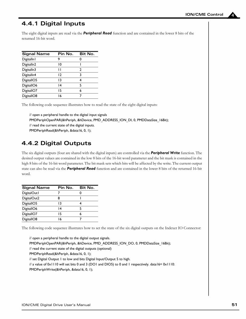
ION/CME Control
ION/CME Digital Drive User’s Manual 51
4
4.4.1 Digital Inputs
The eight digital inputs are read via the Peripheral Read function and are contained in the lower 8 bits of the returned 16-bit word.
The following code sequence illustrates how to read the state of the eight digital inputs:
4.4.2 Digital Outputs
The six digital outputs (four are shared with the digital inputs) are controlled via the Peripheral Write function. The desired output values are contained in the low 8 bits of the 16-bit word parameter and the bit mask is contained in the high 8 bits of the 16-bit word parameter. The bit mask sets which bits will be affected by the write. The current output state can also be read via the Peripheral Read function and are contained in the lower 8 bits of the returned 16-bit word.
The following code sequence illustrates how to set the state of the six digital outputs on the Indexer IO Connector:
Signal Name Pin No. Bit No.DigitalIn1 9 0DigitalIn2 10 1DigitalIn3 11 2DigitalIn4 12 3DigitalIO5 13 4DigitalIO6 14 5DigitalIO7 15 6DigitalIO8 16 7
// open a peripheral handle to the digital input signalsPMDPeriphOpenPAR(&hPeriph, &hDevice, PMD_ADDRESS_ION_DI, 0, PMDDataSize_16Bit);// read the current state of the digital inputs.PMDPeriphRead(&hPeriph, &data16, 0, 1);
Signal Name Pin No. Bit No.DigitalOut1 7 0DigitalOut2 8 1DigitalIO5 13 4DigitalIO6 14 5DigitalIO7 15 6DigitalIO8 16 7
// open a peripheral handle to the digital output signals.PMDPeriphOpenPAR(&hPeriph, &hDevice, PMD_ADDRESS_ION_DO, 0, PMDDataSize_16Bit);// read the current state of the digital outputs (optional)PMDPeriphRead(&hPeriph, &data16, 0, 1);// set Digital Output 1 to low and bits Digital Input/Output 5 to high.// a value of 0x1110 will set bits 0 and 3 (DO1 and DIO5) to 0 and 1 respectively. data16= 0x1110:PMDPeriphWrite(&hPeriph, &data16, 0, 1);
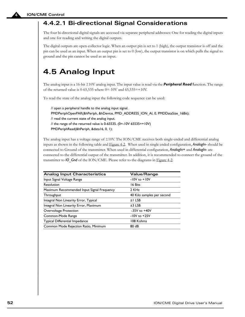
ION/CME Control
52 ION/CME Digital Drive User’s Manual
4
4.4.2.1 Bi-directional Signal Considerations
The four bi-directional digital signals are accessed via separate peripheral addresses: One for reading the digital inputs and one for reading and writing the digital outputs.
The digital outputs are open-collector logic. When an output pin is set to 1 (high), the output transistor is off and the pin can be used as an input. When an output pin is set to 0 (low), the output transistor is on which pulls the signal to ground and the pin cannot be used as an input.
4.5 Analog Input
The analog input is a 16-bit ±10V analog input. The input value is read via the Peripheral Read function. The range of the returned value is 0-65,535 where 0=-10V and 65,535=+10V.
To read the state of the analog input the following code sequence can be used:
The analog input has a voltage range of ±10V. The ION/CME receives both single-ended and differential analog inputs as shown in the following table and Figure 4-2. When used in single ended configuration, AnalogIn- should be connected to Ground of the transmitter. When used in differential configuration, AnalogIn+ and AnalogIn- are connected to the differential output of the transmitter. In addition, it is recommended to connect the ground of the transmitter to IO_Gnd of the ION/CME. Please refer to the diagrams in Figure 4-2.
// open a peripheral handle to the analog input signal.PMDPeriphOpenPAR(&hPeriph, &hDevice, PMD_ADDRESS_ION_AI, 0, PMDDataSize_16Bit);// read the current state of the analog input.// the range of the returned value is 0-65535. (0=-10V 65535=+10V)PMDPeriphRead(&hPeriph, &data16, 0, 1);
Analog Input Characteristics Value/RangeInput Signal Voltage Range -10V to +10VResolution 16 BitsMaximum Recommended Input Signal Frequency 2 KHzThroughput 40 Kilo samples per secondIntegral Non Linearity Error, Typical ±1 LSBIntegral Non Linearity Error, Maximum ±3 LSBOvervoltage Protection -35V to +40VCommon-Mode Range -10V to +25VTypical Differential Impedance 108 KohmsCommon Mode Rejection Ratio, Minimum 80 dB
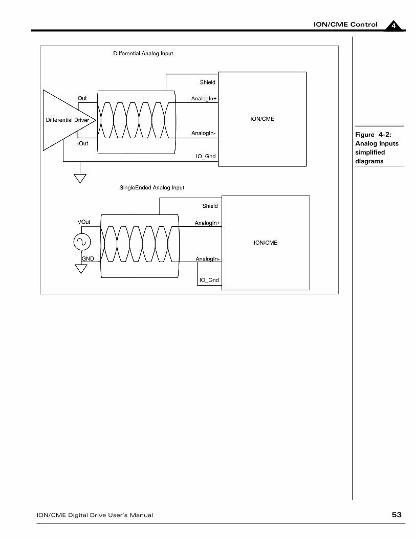
ION/CME Control
ION/CME Digital Drive User’s Manual 53
4
Figure 4-2: Analog inputs simplified diagrams
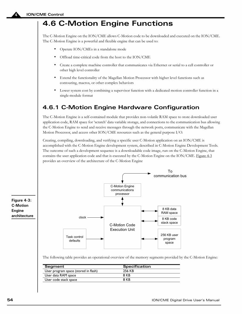
ION/CME Control
54 ION/CME Digital Drive User’s Manual
4
4.6 C-Motion Engine Functions
The C-Motion Engine on the ION/CME allows C-Motion code to be downloaded and executed on the ION/CME. The C-Motion Engine is a powerful and flexible engine that can be used to:
• Operate ION/CMEs in a standalone mode
• Offload time-critical code from the host to the ION/CME
• Create a complete machine controller that communicates via Ethernet or serial to a cell controller or other high level controller
• Extend the functionality of the Magellan Motion Processor with higher level functions such as contouring, macros, or other complex behaviors
• Lower system cost by combining a supervisor function with a dedicated motion controller function in a single-module format
4.6.1 C-Motion Engine Hardware Configuration
The C-Motion Engine is a self-contained module that provides non-volatile RAM space to store downloaded user application code, RAM space for ‘scratch’ data variable storage, and connections to the communication bus allowing the C-Motion Engine to send and receive messages through the network ports, communicate with the Magellan Motion Processor, and access other ION/CME resources such as the general purpose I/O.
Creating, compiling, downloading, and verifying a specific user C-Motion application on an ION/CME is accomplished with the C-Motion Engine development system, described in C-Motion Engine Development Tools. The outcome of such a development sequence is a downloadable code image, run on the C-Motion Engine, that contains the user application code and that is executed by the C-Motion Engine on the ION/CME. Figure 4-3 provides an overview of the architecture of the C-Motion Engine
The following table provides an operational overview of the memory segments provided by the C-Motion Engine:
Segment SpecificationUser program space (stored in flash) 256 KBUser data RAM space 8 KBUser code stack space 8 KB
C-Motion Code
Execution Unit
8 KB data
RAM space
8 KB code
stack space
256 KB user
program
space
C-Motion Engine
communications
processor
To
communication bus
Task control
defaults
clock
Figure 4-3: C-Motion Engine architecture
ION/CME Control
ION/CME Digital Drive User’s Manual 55
4
4.6.2 Powerup & Operation
Upon reset or power up the C-Motion Engine initializes itself and checks to see whether execution of user application code, if downloaded, should automatically begin. If the factory default settings have not been changed, the C-Motion Engine will hold in a wait state, and code execution will not occur.
While there are numerous safety checks and features built into the C-Motion Engine system, application code developed for the C-Motion Engine is C-based, and thus there are limits to code size, RAM usage, and stack usage that should be observed during run time operation of downloaded C-Motion code. The table in the previous section provides these numerical limits.
For user downloaded code that does not correctly observe these limits, or for files that have become corrupted, there are a number of fault conditions that can occur while the C-Motion Engine is executing downloaded user application code. These very serious run-time faults include instruction errors - indicating that an unknown instruction was encountered during execution of the user’s code, and address faults - indicating that either a program space or RAM space access limit was violated. If either of these conditions occurs, the C-Motion Engine will immediately halt user code execution, and reset the ION/CME. This C-Motion Engine-initiated reset is identical to the reset that occurs after sending a PRP Reset action, except that the cause of the reset is recorded as ‘C-Motion Engine user code Fault’ rather than ‘commanded’ reset. See Section 2.8, Applying Power, for more information on the Reset command and on retrieving the reset cause.
Whether or not user application code is running, after reset or power up, the C-Motion Engine begins processing PRP actions sent to it. These commands are typically sent from a host controller. The supported commands include functions such as checking the downloaded user application code version stored in the C-Motion Engine, and sending and receiving messages to the user code loaded onto the C-Motion Engine.
For additional guidelines on managing run-time usage of the C-Motion Engine see the C-Motion Engine Development Tools Manual.
4.6.3 Task Control
The primary purpose of the C-Motion Engine is to execute user application code that has been downloaded to it using the C-Motion Engine development system.
In a production environment, this code will typically automatically start upon power up, and run continuously while the system is in operation. For debugging however, there are a number of additional controls.
At any point in time it is possible to stop or restart execution of the C-Motion Engine user application code. To access this function the PRP action Command is sent to the CMotionEngine resource.
Whether or not the user application code automatically executes upon powerup or reset can also be controlled. The two options are operation under manual mode, in which case the user’s code will not begin execution until an explicit start command is given, and auto-start, where the code automatically begins execution from power up or reset. The PRP action Set sent to the CMotionEngine resource allows setting of the user code start mode.
In addition to these functions, it is also possible to determine whether the user application code is presently running or not. This status information may be useful during code debugging, or to help diagnose problems. This capability is accessed via a Get action sent to the CMotionEngine resource.
Extreme caution should be exercised when stopping or starting user application code running on the C-Motion Engine, as this may cause unexpected or unsafe motion. It is the responsibility of the user to determine whether stopping or restarting of user application code is safe and appropriate.
ION/CME Control
56 ION/CME Digital Drive User’s Manual
4
For a detailed description of the supported ION/CME commands, see the PMD Remote Access Protocol Programmer’s Reference.
4.6.4 Sending Messages To/From User Application Code
A common function of user application code running on the C-Motion Engine is to parse command messages sent to it by a host controller. For example, a user might write code for the C-Motion Engine that responds to an “Extend Robot Arm” command sent by the host controller, and then send a series of commands to the Magellan Motion Processor to execute this motion sequence. At the end of the motion sequence the user application code might send an “Arm Extended” message confirming the movement sequence has completed.
One method of achieving this is to use the ION/CME’s peripheral mechanism to open, and operate, a low-level communications link via the Ethernet or serial link. This method has the advantage of giving relatively direct control over the communication traffic. The disadvantage is that the user has to implement specific send and receive communications in the host controller, and the C-Motion Engine needs to have similar code implemented that can process these messages.
Another method that may be more convenient, particularly during early debugging of the user’s application code, is to use the capability of the PRP system to connect directly to the user application code on the C-Motion Engine. Messages sent and received by the C-Motion Engine from a host controller are stored in a special buffer, and can be easily read or written to by the user application code. In addition, PMD’s Pro-Motion application supports a simple way of entering, sending, and/or receiving such messages. This makes it easy to manually enter commands from Pro-Motion and exercise the user application code which is programmed to parse these messages.
To utilize this approach, a PRP Send or Receive action is sent to the CMotionEngine resource. To receive these messages within the C-Motion Engine a special ‘user packet’ peripheral is opened. For more information see the PMD Resource Access Protocol Programmer’s Reference.
In addition to these communications commands, when sent to the CMotionEngine resource, the PRP action NOP performs a basic connection check. The message body is empty. A return without a PRP error code indicates that the C-Motion Engine is accessible and processing commands.
4.6.5 Connecting To the C-Motion Engine Code During Development
To develop code that is downloaded to the C-Motion Engine, a communications link is required between the C-Motion Engine and the PC-based C-Motion Engine Development Environment. This link contains the information required for code downloads, as well as other information utilized during application debugging.
While Ethernet or serial can both be used as the communications link, typically this link is chosen to be Ethernet because it is significantly faster than the other two. If the ‘production machine’ network is also Ethernet, then only one network need be used for both code development, and operation of the machine.
It is also possible to use separate communication channels, so that one type of link is used for code development and download, and another for the ‘application’ communications. This has the advantage that application and code development traffic are not intermingled. For example, in a production machine control application that involves a PC and two ION/CMEs communicating via serial, Ethernet can be used as the development link, while the application software contained in the C-Motion code will send and receive messages using the serial port.
Selecting which ION/CME channel will be used for download is specified via the C-Motion development system. For more information see the C-Motion Engine Development Tools Manual.
ION/CME Control
ION/CME Digital Drive User’s Manual 57
4
4.6.6 Debug Console Window
During development, the user can use procedure calls similar to printf() from the downloaded application on the C-Motion Engine to send messages to the PC Development Environment for display in a special console window. These console messages may be useful for checking code progress, displaying internal variables, or for other code development-related purposes.
The default console channel is set to 'none', and should be set to a specific Ethernet TCP port to be used during debug. The easiest way to do this is with Pro-Motion using the appropriate setup screens. Alternatively, the PRP action Set with the CMotionEngine resource and Console sub-action can be used to set the console channel.
4.6.7 Downloading and Verifying User Application Code
The C-Motion Engine development system is used to create, compile, and download user application code. The development system can download the file image for the current code project being worked on, or a specific named file can be downloaded. Downloaded files images end with a “.bin” extension. Only one code image file may be downloaded into the C-Motion Engine at a time. Downloading a new image automatically erases the previous code image.
There are times when it may be useful to read specific characteristics of a code file that has been downloaded into the C-Motion Engine. For example, a host controller in a production environment may want to confirm that the host application code version actually loaded on the C-Motion Engine matches the expected production code version. To accomplish this, the PRP action Get is used, specifying a resource ID of CMotionEngine. Using this command the file name of the downloaded user application code, the checksum of the downloaded file, the date & time of file creation, and the version number of the C-Motion Engine itself (loaded by PMD during production) can be retrieved.
For complete information on the format and function of these, and other PRP actions, refer to the PMD Remote Access Protocol Programmer’s Reference.
4.7 Communications Functions
The ION/CME provides two different network connection types, Ethernet and Serial. Access to these communication resources is provided via a peripheral connection. A peripheral is a resource, and is utilized by various PRP actions to send and receive messages to network connections.
Basic access to either the Ethernet or Serial port is accomplished by opening a peripheral with the detailed connection parameters that will be used during communications associated with that peripheral connection, and then sending and receiving messages via that peripheral resource address.
For example, to create an Ethernet TCP peripheral connection, the IP Address and port number is provided. If the connection is successfully established, that peripheral is used as the reference for any future communications through that connection.
In the subsequent sections the operational characteristics of the Serial and Ethernet network ports will be detailed.
ION/CME Control
58 ION/CME Digital Drive User’s Manual
4
4.7.1 Ethernet Communications
The ION/CMEs support two different Ethernet protocols, TCP (Transmission Control Protocol) and UDP (User Datagram Protocol). TCP is typically used for primary Ethernet communications to the ION/CME, while UDP is typically used for non-critical applications such as data logging, or for the Pro-Motion console window. See Section 4.6.6, Debug Console Window, for more information on the C-Motion Engine console window.
When used to receive PRP messages, the physical node on the Ethernet network controller is assigned a 32-bit IP (Internet Protocol) address, along with a 32-bit net mask and a 32-bit gateway value. The Netmask is used to indicate which IP addresses are local, and the gateway value is used to route non-local addresses. To correctly receive communications from the host controller, a 16-bit identifier known as a port must also be specified. Note that when used as the connection between the host controller and the ION/CME, TCP rather than UDP communications are used. To determine what the unused IP addresses are for your Ethernet network, and what values for net mask and gateway to use, contact your network administrator.
The table below shows the range and default settings for the Ethernet controller of the ION/CME:
Each physical hardware device on an Ethernet network is assigned one IP address; however, a given IP address can have multiple ports. This is useful because it allows user application code running on the C-Motion Engine to open up peripheral connections using port numbers other than the PRP communications port (which has a default value of 40100), thereby allowing PRP messages and application-specific data in any format to co-exist on the same Ethernet IP node.
To create an Ethernet/TCP or Ethernet/UDP peripheral conversation, the IP Address and port are specified in the PRP message body of an Open command sent to the Device resource. To transfer messages via this peripheral connection the PRP actions Send and Receive sent to the Peripheral resource are used.
After a reset or at power-up, the ION/CME retrieves default information for the ION/CME Stand-Alone Ethernet port. To change these default values, the PRP Set command is sent to the Device resource.
For detailed information on PRP action formats and function, refer to the PMD Remote Access Protocol Programmer’s Reference.
The PRP messaging system utilizes a default TCP port address of 40100, so this address should not be used for user-created application communications.
By convention, the 32-bit values for IP Address, Net mask, and Gateway are shown in Dotted Quad Notation. In this notation each of the four numbers are separated by dots, and denote a decimal value for each byte of the four byte word
Parameter Range DefaultIP address 0.0.0.0 – 255.255.255.255 192.168.2.2Net mask 0.0.0.0 – 255.255.255.255 255.255.255.0Gateway 0.0.0.0 – 255.255.255.255 0.0.0.0PRP Listen TCP Port 0 - 65,535 40100
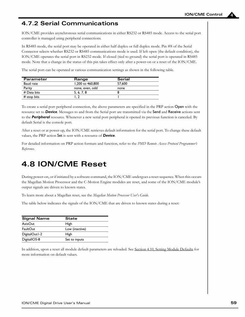
ION/CME Control
ION/CME Digital Drive User’s Manual 59
4
4.7.2 Serial Communications
ION/CME provides asynchronous serial communications in either RS232 or RS485 mode. Access to the serial port controller is managed using peripheral connections.
In RS485 mode, the serial port may be operated in either half duplex or full duplex mode. Pin #8 of the Serial Connector selects whether RS232 or RS485 communications mode is used. If left open (the default condition), the ION/CME operates the serial port in RS232 mode. If closed (tied to ground) the serial port is operated in RS485 mode. Note that a change in the status of this pin takes effect only after a power-on or a reset of the ION/CME.
The serial port can be operated at various communication settings as shown in the following table.
To create a serial port peripheral connection, the above parameters are specified in the PRP action Open with the resource set to Device. Messages to and from the Serial port are transmitted via the Send and Receive actions sent to the Peripheral resource. Whenever a new serial port peripheral is opened its previous function is canceled. By default Serial is the console port.
After a reset or at power-up, the ION/CME retrieves default information for the serial port. To change these default values, the PRP action Set is sent with a resource of Device.
For detailed information on PRP action formats and function, refer to the PMD Remote Access Protocol Programmer’s Reference.
4.8 ION/CME Reset
During power-on, or if initiated by a software command, the ION/CME undergoes a reset sequence. When this occurs the Magellan Motion Processor and the C-Motion Engine modules are reset, and some of the ION/CME module’s output signals are driven to known states.
To learn more about a Magellan reset, see the Magellan Motion Processor User's Guide.
The table below indicates the signals of the ION/CME that are driven to known states during a reset:
In addition, upon a reset all module default parameters are reloaded. See Section 4.10, Setting Module Defaults for more information on default values.
Parameter Range Serial Baud rate 1,200 to 460,800 57,600Parity none, even, odd none# Data bits 5, 6, 7, 8 8# stop bits 1, 2 1
Signal Name StateAxisOut HighFaultOut Low (inactive)DigitalOut1-2 HighDigitalIO5-8 Set to inputs
ION/CME Control
60 ION/CME Digital Drive User’s Manual
4
4.8.1 Software Commanded ION/CME Reset
A reset occurs automatically during power-up, however it is sometimes desirable to reset the ION/CME explicitly through a user-initiated software command. This can be done via the PRP action Reset sent to the Device resource. Note that this command can only be performed when the ION/CME is not in a hard fault condition.
4.9 Non-volatile Memory
The ION/CME module has a general purpose 4,094 byte memory that retains its contents after a module power down or reset. This memory is useful for storing parameters that are set only occasionally and stay with the module, such as machine calibration information.
NVRAM addresses are specified from 0 to 4,093. When writing to this memory, a typical write takes 30 Secs, however under certain circumstances it can take much longer, up to several 100 mSec. Read speed takes just a few nanoseconds. Byte-size memory operations are not supported by the non-volatile memory. The smallest memory unit that can be accessed is 16 bits.
The non-volatile memory can be rewritten a limited number of times. The worst case write limit cycle is 100,000 times for a given memory address, but in typical operation, the limit is much higher. As a general guideline, to avoid erase/ write cycle limit problems, the non-volatile RAM should not be used for general purpose scratch RAM, and should only be used to store permanent or semi-permanent parameters.
To read or write to the NVRAM, a resource address must first be obtained by sending the Open action to the Memory resource. This resource address is used for all further access to the NVRAM. To write data to the NVRAM, the action Write is sent to the Memory resource. To read the contents of the NVRAM, the action Read is used.
For complete information on the format and function of these, and other PRP actions, refer to the PMD Resource Access Protocol Programmer’s Reference.
An ION/CME software reset cannot be performed if the module is in a hard fault state. If attempted, a return error of PMD_ERR_MP_HardFault will occur, and an ION/CME reset will not occur. To reset the ION/CME in this condition you must power cycle the ION unit.
The typical write time to the non-volatile RAM is 30 Sec, however it may take as long as several 100 mSec. If other portions of the user application code, or any other PRP-connected device, depends on these values having been written, it is recommended that you ensure that the write operation has been completed by adding code that explicitly checks the value, or by waiting a fixed period of time after the NVRAM write operation.
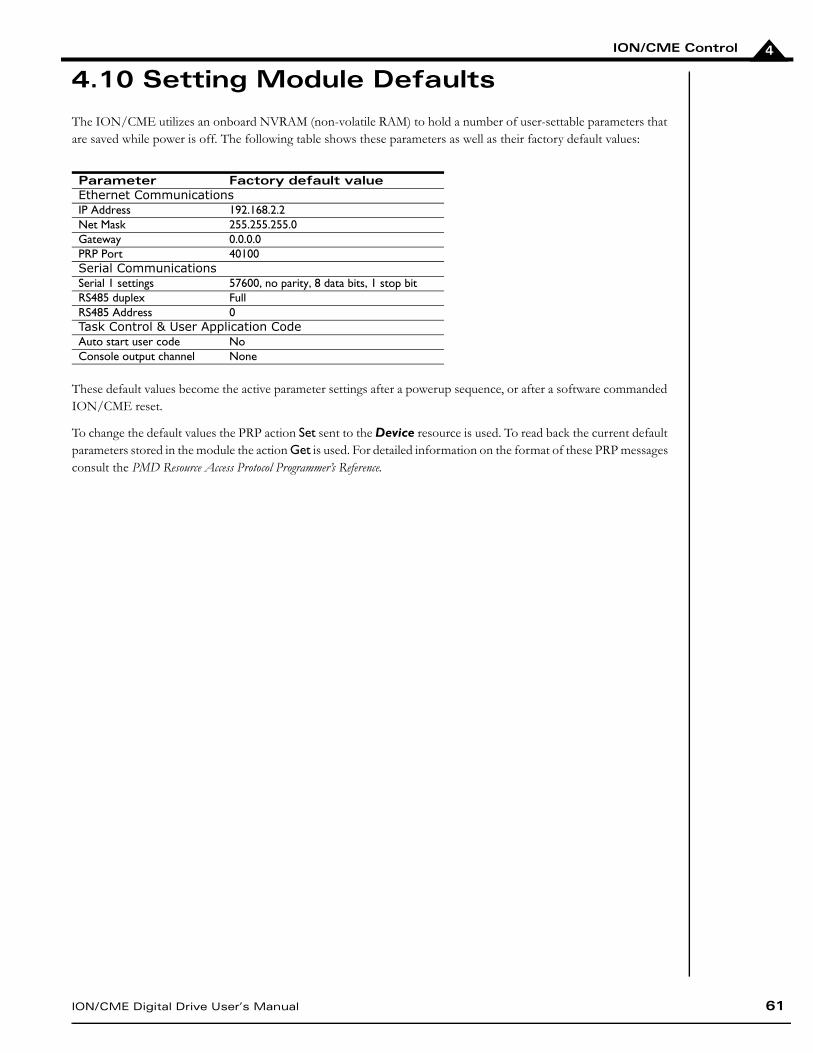
ION/CME Control
ION/CME Digital Drive User’s Manual 61
4
4.10 Setting Module Defaults
The ION/CME utilizes an onboard NVRAM (non-volatile RAM) to hold a number of user-settable parameters that are saved while power is off. The following table shows these parameters as well as their factory default values:
These default values become the active parameter settings after a powerup sequence, or after a software commanded ION/CME reset.
To change the default values the PRP action Set sent to the Device resource is used. To read back the current default parameters stored in the module the action Get is used. For detailed information on the format of these PRP messages consult the PMD Resource Access Protocol Programmer’s Reference.
Parameter Factory default valueEthernet CommunicationsIP Address 192.168.2.2Net Mask 255.255.255.0Gateway 0.0.0.0PRP Port 40100Serial CommunicationsSerial 1 settings 57600, no parity, 8 data bits, 1 stop bitRS485 duplex FullRS485 Address 0Task Control & User Application CodeAuto start user code NoConsole output channel None
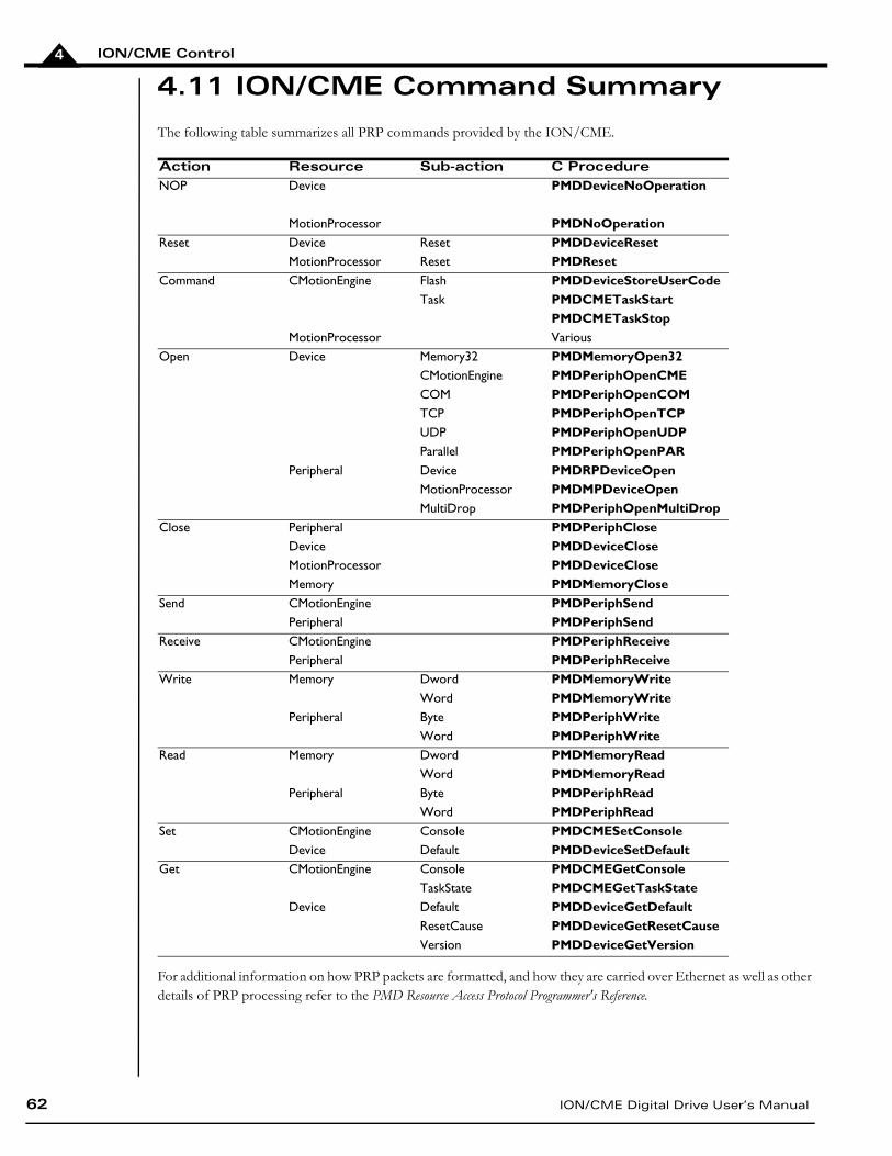
ION/CME Control
62 ION/CME Digital Drive User’s Manual
4
4.11 ION/CME Command Summary
The following table summarizes all PRP commands provided by the ION/CME.
For additional information on how PRP packets are formatted, and how they are carried over Ethernet as well as other details of PRP processing refer to the PMD Resource Access Protocol Programmer's Reference.
Action Resource Sub-action C ProcedureNOP Device PMDDeviceNoOperation
MotionProcessor PMDNoOperationReset Device Reset PMDDeviceReset
MotionProcessor Reset PMDResetCommand CMotionEngine Flash PMDDeviceStoreUserCode
Task PMDCMETaskStartPMDCMETaskStop
MotionProcessor VariousOpen Device Memory32 PMDMemoryOpen32
CMotionEngine PMDPeriphOpenCMECOM PMDPeriphOpenCOMTCP PMDPeriphOpenTCPUDP PMDPeriphOpenUDPParallel PMDPeriphOpenPAR
Peripheral Device PMDRPDeviceOpenMotionProcessor PMDMPDeviceOpenMultiDrop PMDPeriphOpenMultiDrop
Close Peripheral PMDPeriphCloseDevice PMDDeviceCloseMotionProcessor PMDDeviceCloseMemory PMDMemoryClose
Send CMotionEngine PMDPeriphSendPeripheral PMDPeriphSend
Receive CMotionEngine PMDPeriphReceivePeripheral PMDPeriphReceive
Write Memory Dword PMDMemoryWriteWord PMDMemoryWrite
Peripheral Byte PMDPeriphWriteWord PMDPeriphWrite
Read Memory Dword PMDMemoryReadWord PMDMemoryRead
Peripheral Byte PMDPeriphReadWord PMDPeriphRead
Set CMotionEngine Console PMDCMESetConsoleDevice Default PMDDeviceSetDefault
Get CMotionEngine Console PMDCMEGetConsoleTaskState PMDCMEGetTaskState
Device Default PMDDeviceGetDefaultResetCause PMDDeviceGetResetCauseVersion PMDDeviceGetVersion
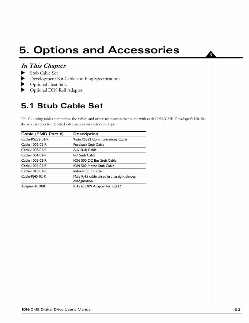
ION/CME Digital Drive User’s Manual 63
55. Options and AccessoriesIn This ChapterStub Cable SetDevelopment Kit Cable and Plug SpecificationsOptional Heat Sink Optional DIN Rail Adapter
5.1 Stub Cable Set
The following tables summarize the cables and other accessories that come with each ION/CME Developer’s Kit. See the next section for detailed information on each cable type.
Cable (PMD Part #) DescriptionCable-RS232-03-R 9-pin RS232 Communications CableCable-1002-02-R Feedback Stub CableCable-1003-02-R Aux Stub CableCable-1004-02-R I/O Stub CableCable-1005-02-R ION 500 DC Bus Stub CableCable-1006-02-R ION 500 Motor Stub CableCable-1010-01-R Indexer Stub CableCable-RJ45-02-R Male RJ45 cable wired in a straight-through
configurationAdapter-1010-01 RJ45 to DB9 Adapter for RS232
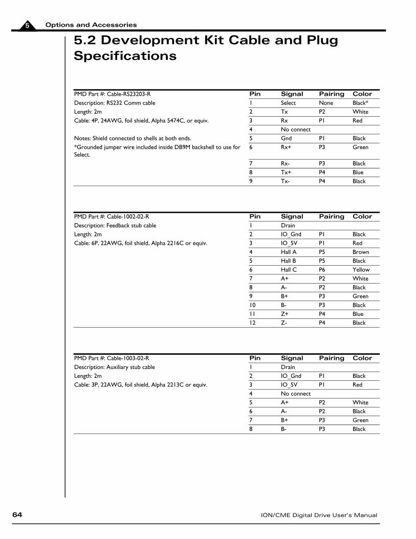
Options and Accessories
64 ION/CME Digital Drive User’s Manual
5
5.2 Development Kit Cable and Plug Specifications
PMD Part #: Cable-RS23203-R Pin Signal Pairing ColorDescription: RS232 Comm cable 1 Select None Black*Length: 2m 2 Tx P2 WhiteCable: 4P, 24AWG, foil shield, Alpha 5474C, or equiv. 3 Rx P1 Red
4 No connectNotes: Shield connected to shells at both ends. 5 Gnd P1 Black*Grounded jumper wire included inside DB9M backshell to use for Select.
6 Rx+ P3 Green
7 Rx- P3 Black8 Tx+ P4 Blue9 Tx- P4 Black
PMD Part #: Cable-1002-02-R Pin Signal Pairing ColorDescription: Feedback stub cable 1 DrainLength: 2m 2 IO_Gnd P1 BlackCable: 6P, 22AWG, foil shield, Alpha 2216C or equiv. 3 IO_5V P1 Red
4 Hall A P5 Brown5 Hall B P5 Black6 Hall C P6 Yellow7 A+ P2 White8 A- P2 Black9 B+ P3 Green10 B- P3 Black11 Z+ P4 Blue12 Z- P4 Black
PMD Part #: Cable-1003-02-R Pin Signal Pairing ColorDescription: Auxiliary stub cable 1 DrainLength: 2m 2 IO_Gnd P1 BlackCable: 3P, 22AWG, foil shield, Alpha 2213C or equiv. 3 IO_5V P1 Red
4 No connect5 A+ P2 White6 A- P2 Black7 B+ P3 Green8 B- P3 Black
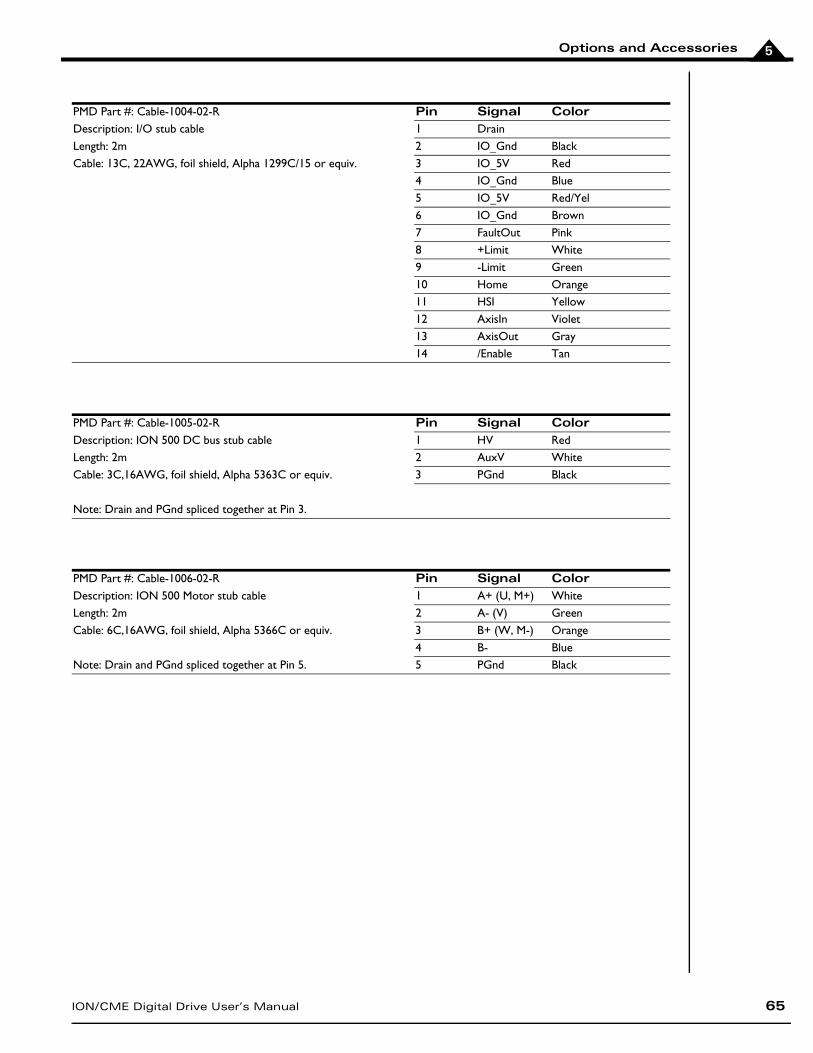
Options and Accessories
ION/CME Digital Drive User’s Manual 65
5
PMD Part #: Cable-1004-02-R Pin Signal ColorDescription: I/O stub cable 1 DrainLength: 2m 2 IO_Gnd BlackCable: 13C, 22AWG, foil shield, Alpha 1299C/15 or equiv. 3 IO_5V Red
4 IO_Gnd Blue5 IO_5V Red/Yel6 IO_Gnd Brown7 FaultOut Pink8 +Limit White9 -Limit Green10 Home Orange11 HSI Yellow12 AxisIn Violet13 AxisOut Gray14 /Enable Tan
PMD Part #: Cable-1005-02-R Pin Signal ColorDescription: ION 500 DC bus stub cable 1 HV RedLength: 2m 2 AuxV WhiteCable: 3C,16AWG, foil shield, Alpha 5363C or equiv. 3 PGnd Black
Note: Drain and PGnd spliced together at Pin 3.
PMD Part #: Cable-1006-02-R Pin Signal ColorDescription: ION 500 Motor stub cable 1 A+ (U, M+) WhiteLength: 2m 2 A- (V) GreenCable: 6C,16AWG, foil shield, Alpha 5366C or equiv. 3 B+ (W, M-) Orange
4 B- BlueNote: Drain and PGnd spliced together at Pin 5. 5 PGnd Black
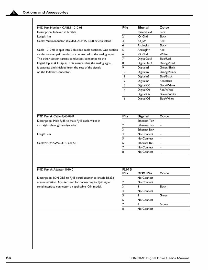
Options and Accessories
66 ION/CME Digital Drive User’s Manual
5
PMD Part Number: CABLE-1010-01 Pin Signal ColorDescription: Indexer stub cable 1 Case Shield BareLength: 1m 2 IO_Gnd BlackCable: Multiconductor shielded, ALPHA 6308 or equivalent 3 IO_5V Red
4 AnalogIn- BlackCable-1010-01 is split into 2 shielded cable sections. One section 5 AnalogIn+ Redcarries twisted pair conductors connected to the analog input. 6 IO_Gnd WhiteThe other section carries conductors connected to the 7 DigitalOut1 Blue/RedDigital Inputs & Outputs. This ensures that the analog signal 8 DigitalOut2 Orange/Redis separate and shielded from the rest of the signals 9 DigitalIn1 Green/Blackon the Indexer Connector. 10 DigitalIn2 Orange/Black
11 DigitalIn3 Blue/Black12 DigitalIn4 Red/Black13 DigitalIO5 Black/White14 DigitalIO6 Red/White15 DigitalIO7 Green/White16 DigitalIO8 Blue/White
PMD Part #: Cable-RJ45-02-R Pin Signal ColorDescription: Male RJ45 to male RJ45 cable wired in 1 Ethernet Tx+ -a straight- through configuration 2 Ethernet Tx- -
3 Ethernet Rx+ -Length: 2m 4 No Connect -
5 No Connect -Cable:4P, 24AWG,UTP, Cat 5E 6 Ethernet Rx- -
7 No Connect -8 No Connect -
PMD Part #: Adapter-1010-01 RJ45 Pin DB9 Pin Color
Description: ION DB9 to RJ45 serial adapter to enable RS232 1 No Connectcommunication. Adapter used for connecting to RJ45 style 2 No Connectserial interface connector on applicable ION model. 3 3 Black
4 No Connect5 2 Green6 No Connect7 5 Brown8 No Connect
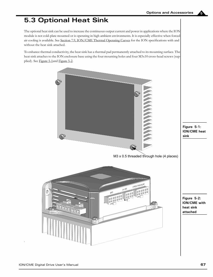
Options and Accessories
ION/CME Digital Drive User’s Manual 67
5
5.3 Optional Heat Sink
The optional heat sink can be used to increase the continuous output current and power in applications where the ION module is not cold-plate mounted or is operating in high ambient environments. It is especially effective when forced air cooling is available. See Section 7.9, ION/CME Thermal Operating Curves for the ION specifications with and without the heat sink attached.
To enhance thermal conductivity, the heat sink has a thermal pad permanently attached to its mounting surface. The heat sink attaches to the ION enclosure base using the four mounting holes and four M3x10 cross-head screws (sup-plied). See Figure 5-1and Figure 5-2.
.
Figure 5-1: ION/CME heat sink
Figure 5-2: ION/CME with heat sink attached
M3 x 0.5 threaded through hole (4 places)
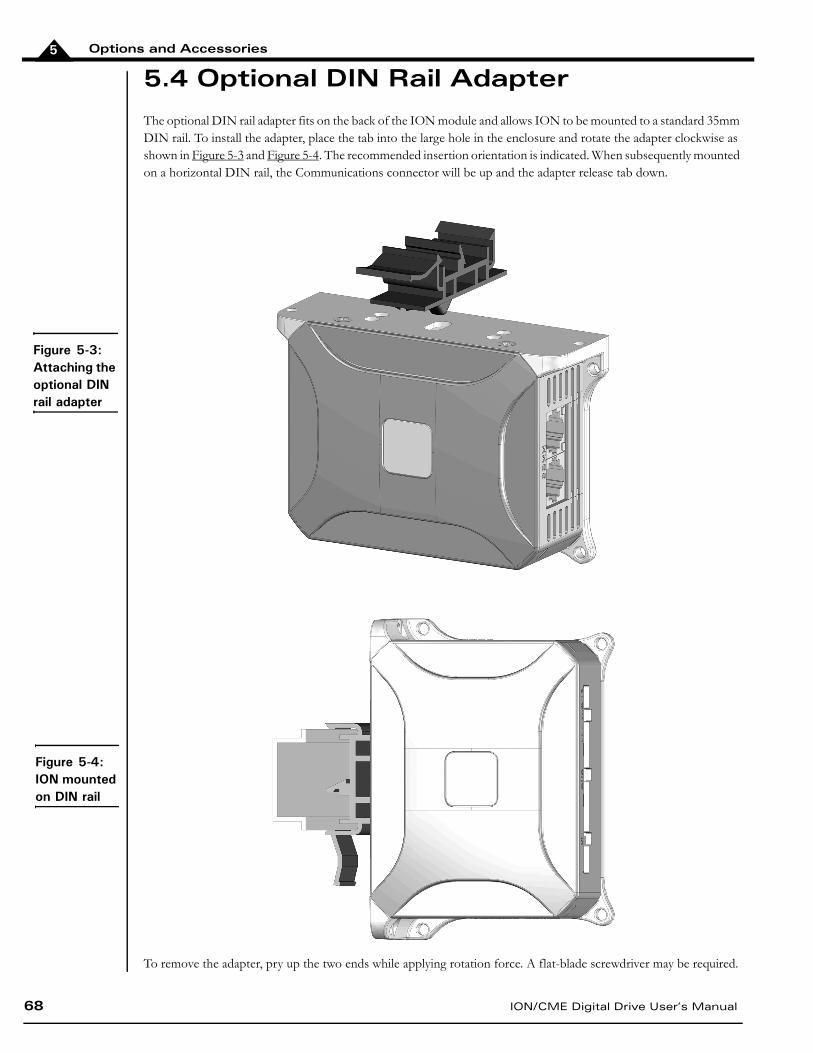
Options and Accessories
68 ION/CME Digital Drive User’s Manual
5
5.4 Optional DIN Rail Adapter
The optional DIN rail adapter fits on the back of the ION module and allows ION to be mounted to a standard 35mm DIN rail. To install the adapter, place the tab into the large hole in the enclosure and rotate the adapter clockwise as shown in Figure 5-3 and Figure 5-4. The recommended insertion orientation is indicated. When subsequently mounted on a horizontal DIN rail, the Communications connector will be up and the adapter release tab down.
To remove the adapter, pry up the two ends while applying rotation force. A flat-blade screwdriver may be required.
Figure 5-3: Attaching the optional DIN rail adapter
Figure 5-4: ION mounted on DIN rail
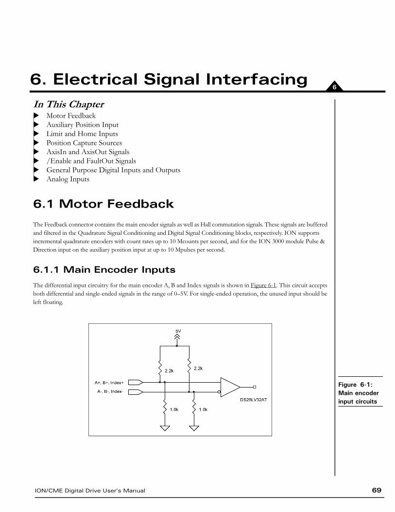
ION/CME Digital Drive User’s Manual 69
66. Electrical Signal InterfacingIn This ChapterMotor FeedbackAuxiliary Position InputLimit and Home InputsPosition Capture Sources AxisIn and AxisOut Signals/Enable and FaultOut SignalsGeneral Purpose Digital Inputs and OutputsAnalog Inputs
6.1 Motor Feedback
The Feedback connector contains the main encoder signals as well as Hall commutation signals. These signals are buffered and filtered in the Quadrature Signal Conditioning and Digital Signal Conditioning blocks, respectively. ION supports incremental quadrature encoders with count rates up to 10 Mcounts per second, and for the ION 3000 module Pulse & Direction input on the auxiliary position input at up to 10 Mpulses per second.
6.1.1 Main Encoder Inputs
The differential input circuitry for the main encoder A, B and Index signals is shown in Figure 6-1. This circuit accepts both differential and single-ended signals in the range of 0–5V. For single-ended operation, the unused input should be left floating.
Figure 6-1: Main encoder input circuits
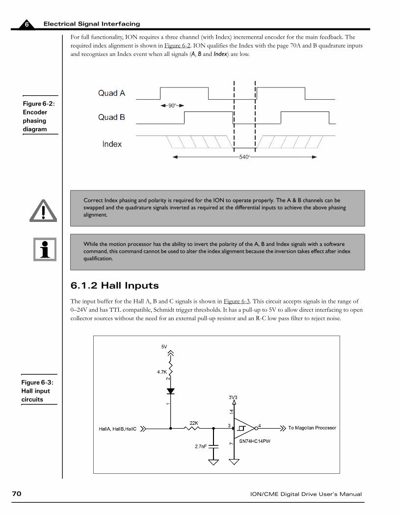
Electrical Signal Interfacing
70 ION/CME Digital Drive User’s Manual
6
For full functionality, ION requires a three channel (with Index) incremental encoder for the main feedback. The required index alignment is shown in Figure 6-2. ION qualifies the Index with the page 70A and B quadrature inputs and recognizes an Index event when all signals (A, B and Index) are low.
6.1.2 Hall Inputs
The input buffer for the Hall A, B and C signals is shown in Figure 6-3. This circuit accepts signals in the range of 0–24V and has TTL compatible, Schmidt trigger thresholds. It has a pull-up to 5V to allow direct interfacing to open collector sources without the need for an external pull-up resistor and an R-C low pass filter to reject noise.
Correct Index phasing and polarity is required for the ION to operate properly. The A & B channels can be swapped and the quadrature signals inverted as required at the differential inputs to achieve the above phasing alignment.
While the motion processor has the ability to invert the polarity of the A, B and Index signals with a software command, this command cannot be used to alter the index alignment because the inversion takes effect after index qualification.
Figure 6-2: Encoder phasing diagram
Figure 6-3: Hall input circuits
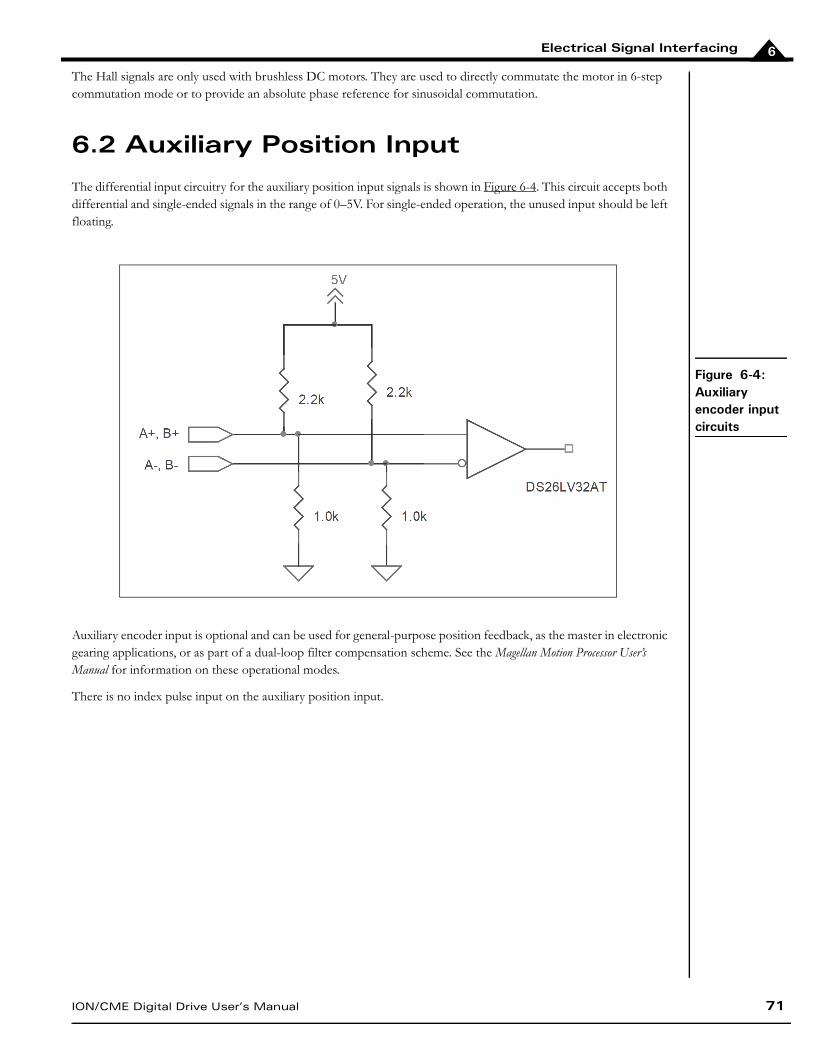
Electrical Signal Interfacing
ION/CME Digital Drive User’s Manual 71
6
The Hall signals are only used with brushless DC motors. They are used to directly commutate the motor in 6-step commutation mode or to provide an absolute phase reference for sinusoidal commutation.
6.2 Auxiliary Position Input
The differential input circuitry for the auxiliary position input signals is shown in Figure 6-4. This circuit accepts both differential and single-ended signals in the range of 0–5V. For single-ended operation, the unused input should be left floating.
Auxiliary encoder input is optional and can be used for general-purpose position feedback, as the master in electronic gearing applications, or as part of a dual-loop filter compensation scheme. See the Magellan Motion Processor User’s Manual for information on these operational modes.
There is no index pulse input on the auxiliary position input.
Figure 6-4: Auxiliary encoder input circuits
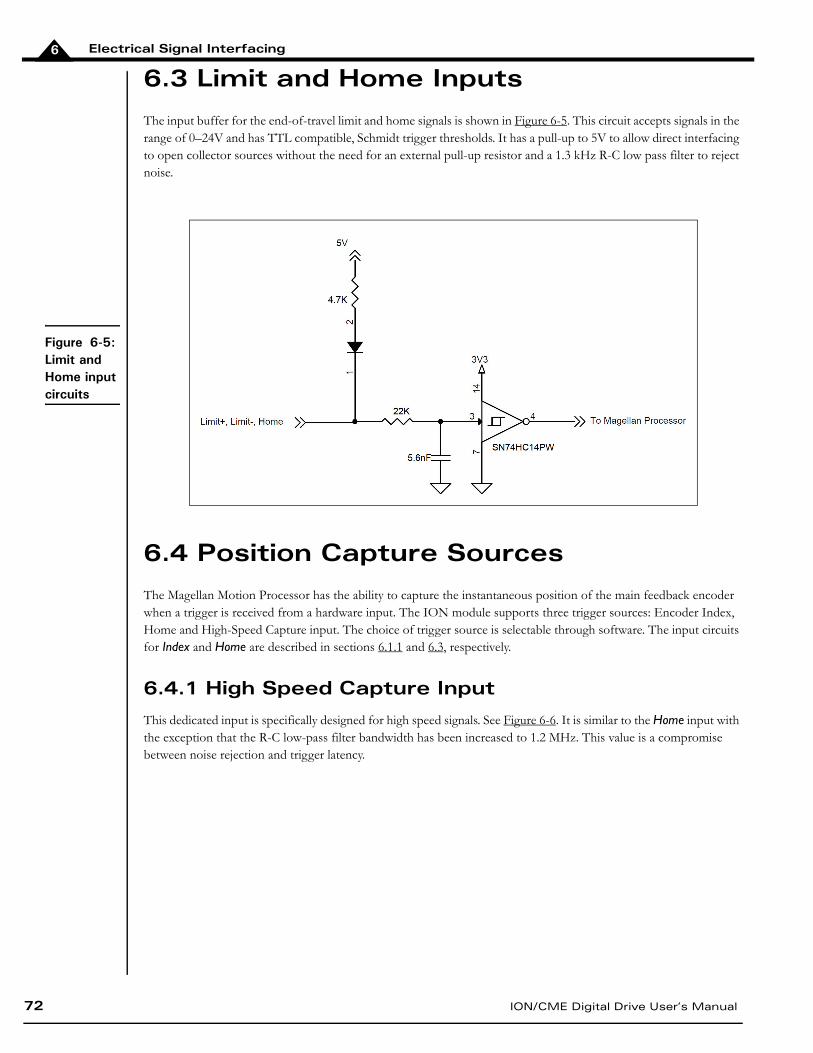
Electrical Signal Interfacing
72 ION/CME Digital Drive User’s Manual
6
6.3 Limit and Home Inputs
The input buffer for the end-of-travel limit and home signals is shown in Figure 6-5. This circuit accepts signals in the range of 0–24V and has TTL compatible, Schmidt trigger thresholds. It has a pull-up to 5V to allow direct interfacing to open collector sources without the need for an external pull-up resistor and a 1.3 kHz R-C low pass filter to reject noise.
6.4 Position Capture Sources
The Magellan Motion Processor has the ability to capture the instantaneous position of the main feedback encoder when a trigger is received from a hardware input. The ION module supports three trigger sources: Encoder Index, Home and High-Speed Capture input. The choice of trigger source is selectable through software. The input circuits for Index and Home are described in sections 6.1.1 and 6.3, respectively.
6.4.1 High Speed Capture Input
This dedicated input is specifically designed for high speed signals. See Figure 6-6. It is similar to the Home input with the exception that the R-C low-pass filter bandwidth has been increased to 1.2 MHz. This value is a compromise between noise rejection and trigger latency.
Figure 6-5: Limit and Home input circuits
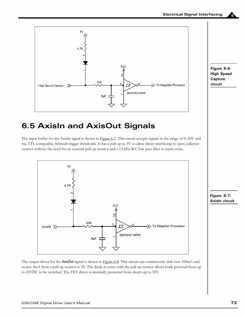
Electrical Signal Interfacing
ION/CME Digital Drive User’s Manual 73
6
6.5 AxisIn and AxisOut Signals
The input buffer for the AxisIn signal is shown in Figure 6-7. This circuit accepts signals in the range of 0–24V and has TTL compatible, Schmidt trigger thresholds. It has a pull-up to 5V to allow direct interfacing to open collector sources without the need for an external pull-up resistor and a 13 kHz R-C low pass filter to reject noise.
The output driver for the AxisOut signal is shown in Figure 6-8. This circuit can continuously sink over 100mA and source 4mA from a pull-up resistor to 5V. The diode in series with the pull-up resistor allows loads powered from up to 24VDC to be switched. The FET driver is internally protected from shorts up to 30V.
Figure 6-6: High Speed Capture circuit
Figure 6-7: AxisIn circuit
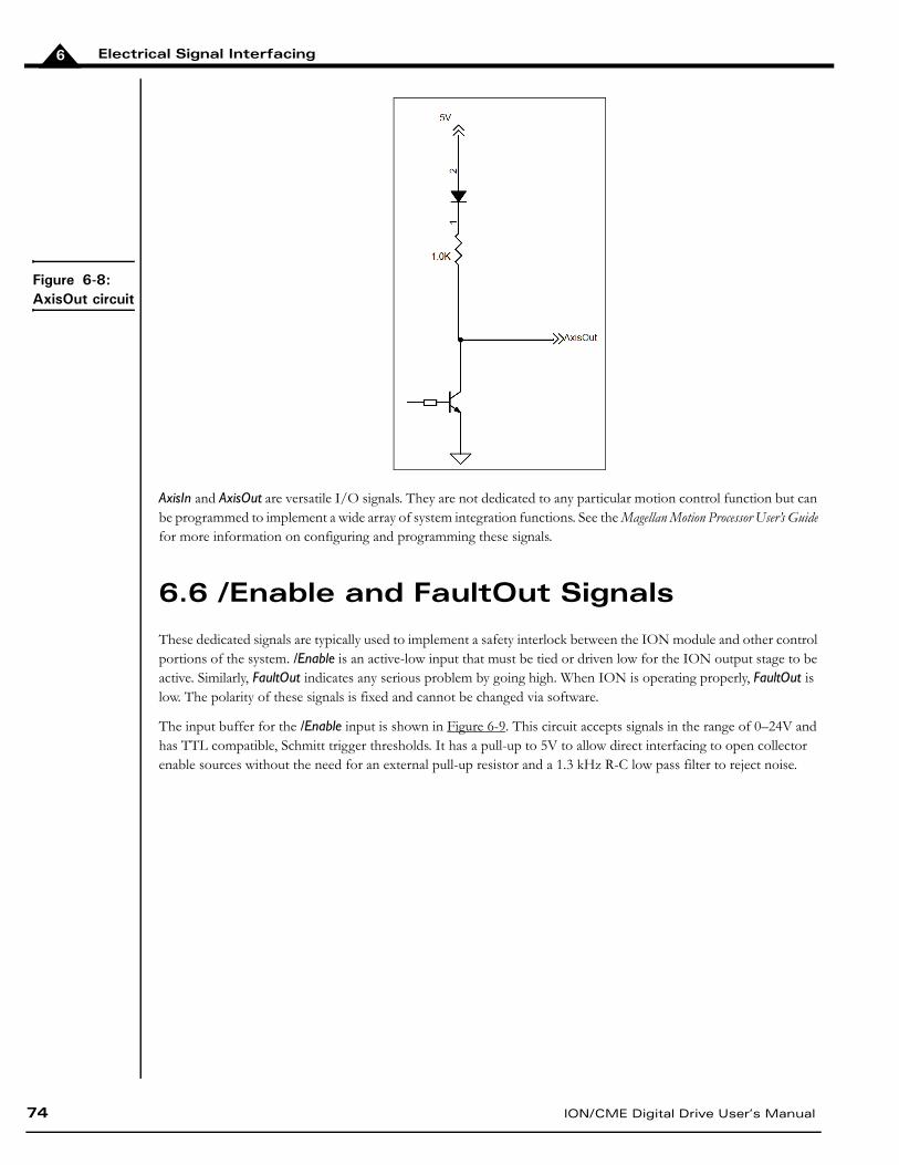
Electrical Signal Interfacing
74 ION/CME Digital Drive User’s Manual
6
AxisIn and AxisOut are versatile I/O signals. They are not dedicated to any particular motion control function but can be programmed to implement a wide array of system integration functions. See the Magellan Motion Processor User’s Guide for more information on configuring and programming these signals.
6.6 /Enable and FaultOut Signals
These dedicated signals are typically used to implement a safety interlock between the ION module and other control portions of the system. /Enable is an active-low input that must be tied or driven low for the ION output stage to be active. Similarly, FaultOut indicates any serious problem by going high. When ION is operating properly, FaultOut is low. The polarity of these signals is fixed and cannot be changed via software.
The input buffer for the /Enable input is shown in Figure 6-9. This circuit accepts signals in the range of 0–24V and has TTL compatible, Schmitt trigger thresholds. It has a pull-up to 5V to allow direct interfacing to open collector enable sources without the need for an external pull-up resistor and a 1.3 kHz R-C low pass filter to reject noise.
Figure 6-8: AxisOut circuit
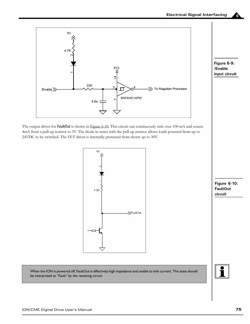
Electrical Signal Interfacing
ION/CME Digital Drive User’s Manual 75
6
The output driver for FaultOut is shown in Figure 6-10. This circuit can continuously sink over 100 mA and source 4mA from a pull-up resistor to 5V. The diode in series with the pull-up resistor allows loads powered from up to 24VDC to be switched. The FET driver is internally protected from shorts up to 30V.
When the ION is powered off, FaultOut is effectively high impedance and unable to sink current. This state should be interpreted as “Fault” by the receiving circuit.
Figure 6-9: /Enable input circuit
Figure 6-10: FaultOut circuit
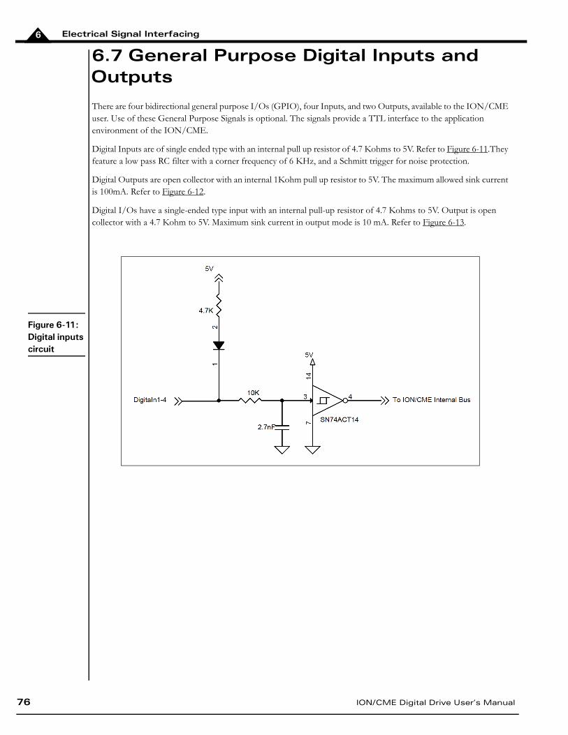
Electrical Signal Interfacing
76 ION/CME Digital Drive User’s Manual
6
6.7 General Purpose Digital Inputs and Outputs
There are four bidirectional general purpose I/Os (GPIO), four Inputs, and two Outputs, available to the ION/CME user. Use of these General Purpose Signals is optional. The signals provide a TTL interface to the application environment of the ION/CME.
Digital Inputs are of single ended type with an internal pull up resistor of 4.7 Kohms to 5V. Refer to Figure 6-11.They feature a low pass RC filter with a corner frequency of 6 KHz, and a Schmitt trigger for noise protection.
Digital Outputs are open collector with an internal 1Kohm pull up resistor to 5V. The maximum allowed sink current is 100mA. Refer to Figure 6-12.
Digital I/Os have a single-ended type input with an internal pull-up resistor of 4.7 Kohms to 5V. Output is open collector with a 4.7 Kohm to 5V. Maximum sink current in output mode is 10 mA. Refer to Figure 6-13.
Figure 6-11: Digital inputs circuit

Electrical Signal Interfacing
ION/CME Digital Drive User’s Manual 77
6
6.8 Analog Inputs
The High Resolution Analog Input has a voltage range of ±10V. The ION/CME receives both single-ended and differential analog inputs as shown in the following table and Figure 6-14. When used in single ended configuration, AnalogIn- should be connected to Ground of the transmitter. When used in differential configuration, AnalogIn+ and AnalogIn- are connected to the differential output of the transmitter. In addition, it is recommended to connect the ground of the transmitter to IO_GND of the ION/CME. Refer to the Figure 6-14.
Figure 6-13: Digital I/O circuit
Figure 6-12: Digital outputs circuit
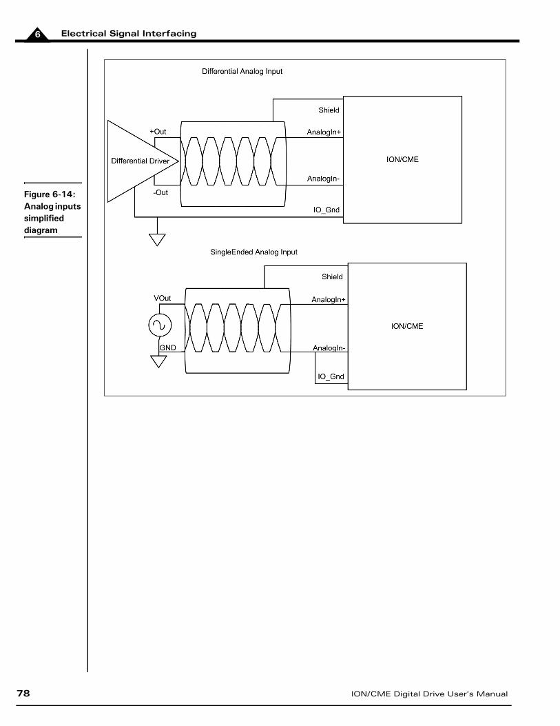
Electrical Signal Interfacing
78 ION/CME Digital Drive User’s Manual
6
Figure 6-14: Analog inputs simplified diagram
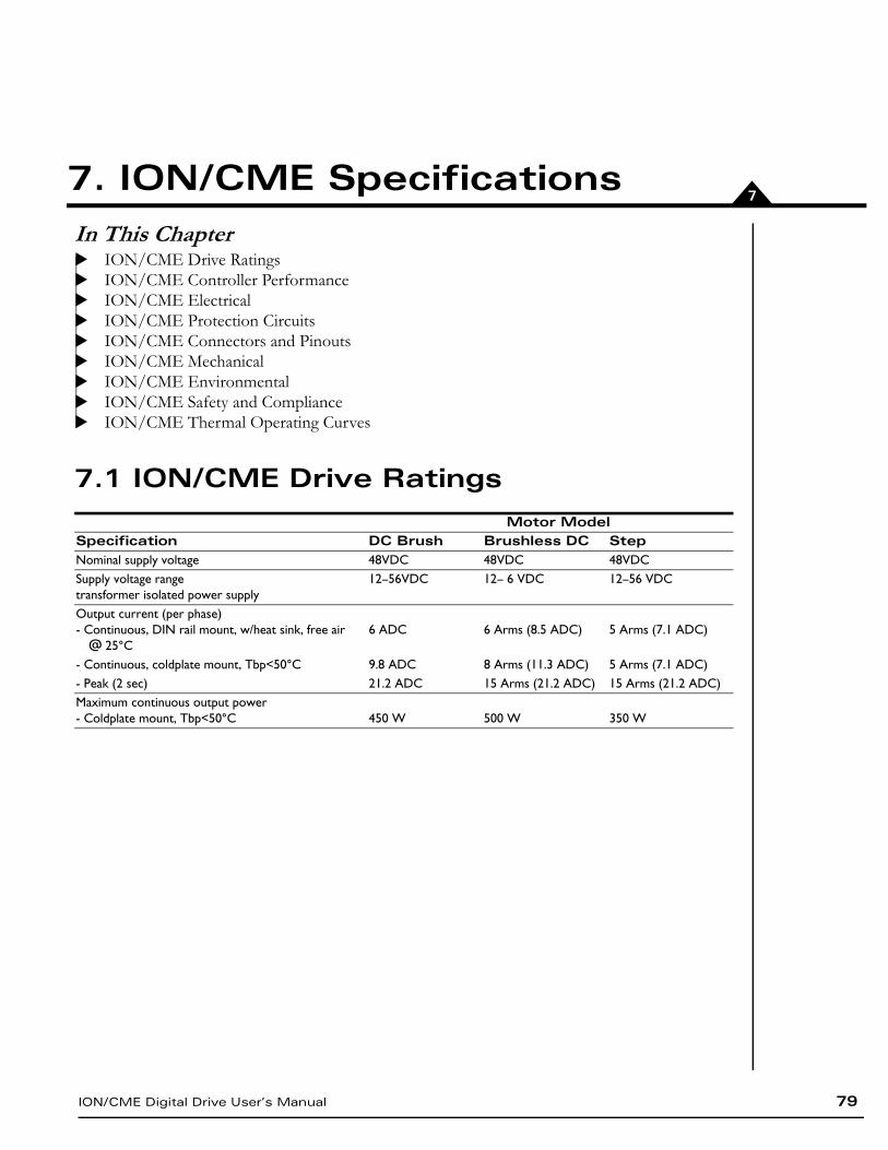
ION/CME Digital Drive User’s Manual 79
77. ION/CME SpecificationsIn This ChapterION/CME Drive RatingsION/CME Controller PerformanceION/CME ElectricalION/CME Protection CircuitsION/CME Connectors and PinoutsION/CME MechanicalION/CME EnvironmentalION/CME Safety and ComplianceION/CME Thermal Operating Curves
7.1 ION/CME Drive RatingsMotor Model
Specification DC Brush Brushless DC StepNominal supply voltage 48VDC 48VDC 48VDCSupply voltage rangetransformer isolated power supply
12–56VDC 12– 6 VDC 12–56 VDC
Output current (per phase)- Continuous, DIN rail mount, w/heat sink, free air
@ 25°C6 ADC 6 Arms (8.5 ADC) 5 Arms (7.1 ADC)
- Continuous, coldplate mount, Tbp<50°C 9.8 ADC 8 Arms (11.3 ADC) 5 Arms (7.1 ADC)- Peak (2 sec) 21.2 ADC 15 Arms (21.2 ADC) 15 Arms (21.2 ADC)Maximum continuous output power- Coldplate mount, Tbp<50°C 450 W 500 W 350 W
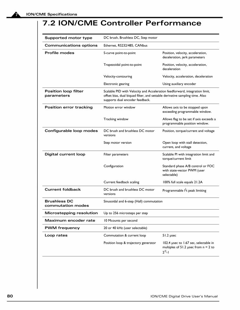
ION/CME Specifications
80 ION/CME Digital Drive User’s Manual
7
7.2 ION/CME Controller Performance
Supported motor type DC brush, Brushless DC, Step motor
Communications options Ethernet, RS232/485, CANbus
Profile modes S-curve point-to-point Position, velocity, acceleration, deceleration, jerk parameters
Trapezoidal point-to-point Position, velocity, acceleration, deceleration
Velocity-contouring Velocity, acceleration, deceleration
Electronic gearing Using auxiliary encoder
Position loop filter parameters
Scalable PID with Velocity and Acceleration feedforward, integration limit, offset bias, dual biquad filter, and settable derivative sampling time. Also supports dual encoder feedback.
Position error tracking Motion error window Allows axis to be stopped upon exceeding programmable window.
Tracking window Allows flag to be set if axis exceeds a programmable position window.
Configurable loop modes DC brush and brushless DC motor versions
Position, torque/current and voltage
Step motor version Open loop with stall detection, current, and voltage
Digital current loop Filter parameters Scalable PI with integration limit and torque/current limit
Configuration Standard phase A/B control or FOC with state-vector PWM (user selectable)
Current feedback scaling 100% full scale equals 21.2A
Current foldback DC brush and brushless DC motor versions
Programmable I2t peak limiting
Brushless DC commutation modes
Sinusoidal and 6-step (Hall) commutation
Microstepping resolution Up to 256 microsteps per step
Maximum encoder rate 10 Mcounts per second
PWM frequency 20 or 40 kHz (user selectable)
Loop rates Commutation & current loop 51.2 µsec
Position loop & trajectory generator 102.4 µsec to 1.67 sec, selectable in multiples of 51.2 µsec from n = 2 to
215-1
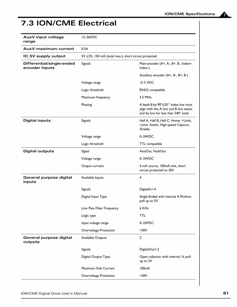
ION/CME Specifications
ION/CME Digital Drive User’s Manual 81
7
7.3 ION/CME Electrical
AuxV input voltage range
12–56VDC
AuxV maximum current 0.5A
IO_5V supply output 5V ±2%, 150 mA (total max.), short circuit protected
Differential/single-ended encoder inputs
Signals Main encoder (A+, A-, B+, B-, Index+, Index-)
Auxiliary encoder (A+, A-, B+, B-)
Voltage range 0–5 VDC
Logic threshold RS422 compatible
Maximum frequency 2.5 MHz
Phasing A leads B by 90°±20°. Index low must align with the A low and B low states and be low for less than 540° total.
Digital inputs Signals Hall A, Hall B, Hall C, Home, +Limit,-Limit, AxisIn, High-speed Capture,/Enable
Voltage range 0–24VDC
Logic threshold TTL compatible
Digital outputs Signal AxisOut, FaultOut
Voltage range 0–24VDC
Output current: 4 mA source, 100mA sink, shortcircuit protected to 30V
General purpose digital inputs
Available Inputs 4
Signals DigitalIn1-4
Digital Input Type Single Ended with internal 4.7Kohms pull up to 5V
Low Pass Filter Frequency 6 KHz
Logic type TTL
Input voltage range 0–24VDC
Overvoltage Protection <30V
General purpose digital outputs
Available Outputs 2
Signals DigitalOut1-2
Digital Output Type Open collector with internal 1k pull-up to 5V
Maximum Sink Current 100mA
Overvoltage Protection <30V
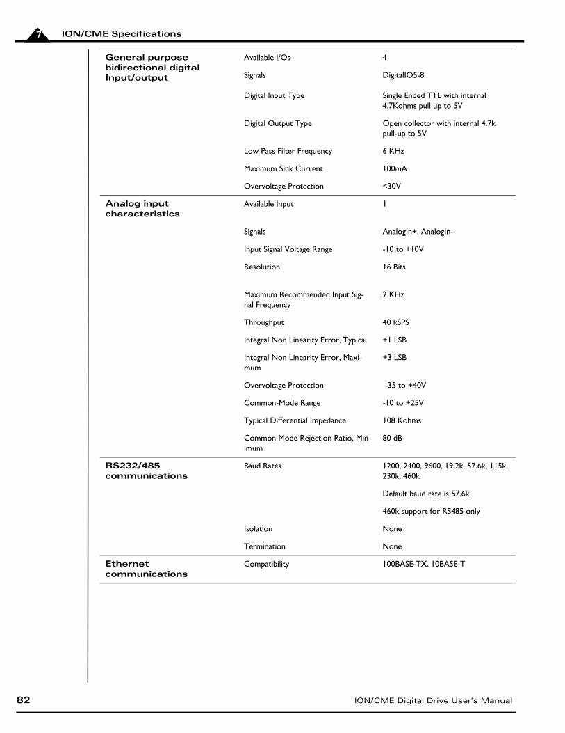
ION/CME Specifications
82 ION/CME Digital Drive User’s Manual
7
General purpose bidirectional digitalInput/output
Available I/Os 4
Signals DigitalIO5-8
Digital Input Type Single Ended TTL with internal 4.7Kohms pull up to 5V
Digital Output Type Open collector with internal 4.7k pull-up to 5V
Low Pass Filter Frequency 6 KHz
Maximum Sink Current 100mA
Overvoltage Protection <30V
Analog inputcharacteristics
Available Input 1
Signals AnalogIn+, AnalogIn-
Input Signal Voltage Range -10 to +10V
Resolution 16 Bits
Maximum Recommended Input Sig-nal Frequency
2 KHz
Throughput 40 kSPS
Integral Non Linearity Error, Typical +1 LSB
Integral Non Linearity Error, Maxi-mum
+3 LSB
Overvoltage Protection -35 to +40V
Common-Mode Range -10 to +25V
Typical Differential Impedance 108 Kohms
Common Mode Rejection Ratio, Min-imum
80 dB
RS232/485communications
Baud Rates 1200, 2400, 9600, 19.2k, 57.6k, 115k, 230k, 460k
Default baud rate is 57.6k.
460k support for RS485 only
Isolation None
Termination None
Ethernetcommunications
Compatibility 100BASE-TX, 10BASE-T
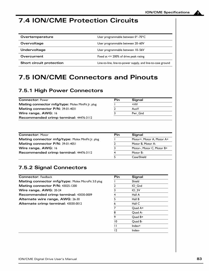
ION/CME Specifications
ION/CME Digital Drive User’s Manual 83
7
7.4 ION/CME Protection Circuits
7.5 ION/CME Connectors and Pinouts
7.5.1 High Power Connectors
7.5.2 Signal Connectors
Overtemperature User programmable between 0°–70°C
Overvoltage User programmable between 20–60V
Undervoltage User programmable between 10–56V
Overcurrent Fixed at <= 200% of drive peak rating
Short circuit protection Line-to-line, line-to-power supply, and line-to-case ground
Connector: Power Pin SignalMating connector mfg/type: Molex MiniFit Jr. plug 1 +HVMating connector P/N: 39-01-4031 2 AuxVWire range, AWG: 16 3 Pwr_GndRecommended crimp terminal: 44476-3112
Connector: Motor Pin SignalMating connector mfg/type: Molex MiniFit Jr. plug 1 Motor+, Motor A, Motor A+Mating connector P/N: 39-01-4051 2 Motor B, Motor A-Wire range, AWG: 16 3 Motor-, Motor C, Motor B+Recommended crimp terminal: 44476-3112 4 Motor B-
5 Case/Shield
Connector: Feedback Pin SignalMating connector mfg/type: Molex MicroFit 3.0 plug 1 ShieldMating connector P/N: 43025-1200 2 IO_GndWire range, AWG: 20-24 3 IO_5VRecommended crimp terminal: 43030-0009 4 Hall AAlternate wire range, AWG: 26-30 5 Hall BAlternate crimp terminal: 43030-0012 6 Hall C
7 Quad A+8 Quad A-9 Quad B+10 Quad B-11 Index+12 Index-
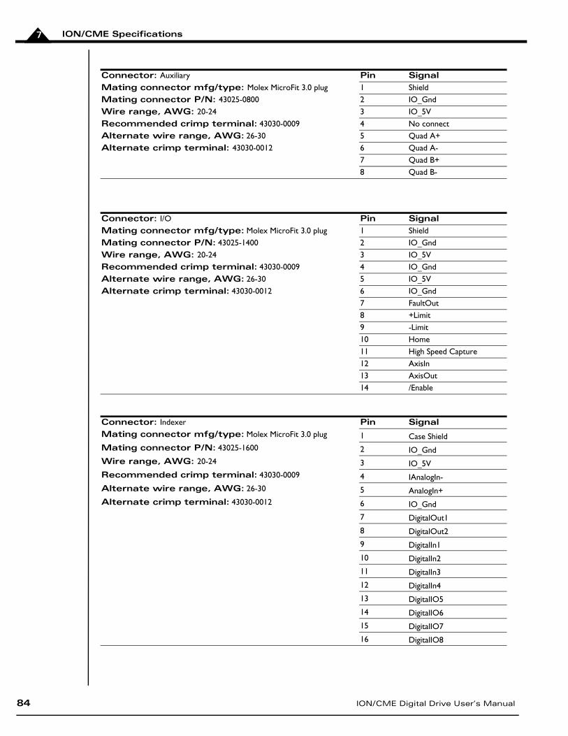
ION/CME Specifications
84 ION/CME Digital Drive User’s Manual
7
Connector: Auxiliary Pin SignalMating connector mfg/type: Molex MicroFit 3.0 plug 1 ShieldMating connector P/N: 43025-0800 2 IO_GndWire range, AWG: 20-24 3 IO_5VRecommended crimp terminal: 43030-0009 4 No connectAlternate wire range, AWG: 26-30 5 Quad A+Alternate crimp terminal: 43030-0012 6 Quad A-
7 Quad B+8 Quad B-
Connector: I/O Pin SignalMating connector mfg/type: Molex MicroFit 3.0 plug 1 ShieldMating connector P/N: 43025-1400 2 IO_GndWire range, AWG: 20-24 3 IO_5VRecommended crimp terminal: 43030-0009 4 IO_GndAlternate wire range, AWG: 26-30 5 IO_5VAlternate crimp terminal: 43030-0012 6 IO_Gnd
7 FaultOut8 +Limit9 -Limit10 Home11 High Speed Capture12 AxisIn13 AxisOut14 /Enable
Connector: Indexer Pin SignalMating connector mfg/type: Molex MicroFit 3.0 plug 1 Case ShieldMating connector P/N: 43025-1600 2 IO_GndWire range, AWG: 20-24 3 IO_5VRecommended crimp terminal: 43030-0009 4 IAnalogIn-Alternate wire range, AWG: 26-30 5 AnalogIn+Alternate crimp terminal: 43030-0012 6 IO_Gnd
7 DigitalOut1
8 DigitalOut2
9 DigitalIn1
10 DigitalIn2
11 DigitalIn3
12 DigitalIn4
13 DigitalIO5
14 DigitalIO6
15 DigitalIO7
16 DigitalIO8
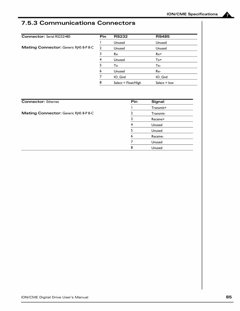
ION/CME Specifications
ION/CME Digital Drive User’s Manual 85
7
7.5.3 Communications Connectors
Connector: Serial RS232/485 Pin RS232 RS485
1 Unused Unused Mating Connector: Generic RJ45 8-P 8-C 2 Unused Unused
3 Rx Rx+
4 Unused Tx+
5 Tx Tx-
6 Unused Rx-
7 IO_Gnd IO_Gnd
8 Select = Float/High Select = low
Connector: Ethernet Pin Signal
1 Transmit+
Mating Connector: Generic RJ45 8-P 8-C 2 Transmit-
3 Receive+
4 Unused
5 Unused
6 Receive-
7 Unused
8 Unused
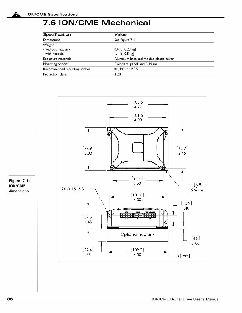
ION/CME Specifications
86 ION/CME Digital Drive User’s Manual
7
7.6 ION/CME Mechanical Specification ValueDimensions See Figure 7-1Weight- without heat sink- with heat sink
0.6 lb [0.28 kg]1.1 lb [0.5 kg]
Enclosure materials Aluminum base and molded plastic coverMounting options Coldplate, panel, and DIN railRecommended mounting screws #6, M3, or M3.5Protection class IP20
Figure 7-1: ION/CME dimensions
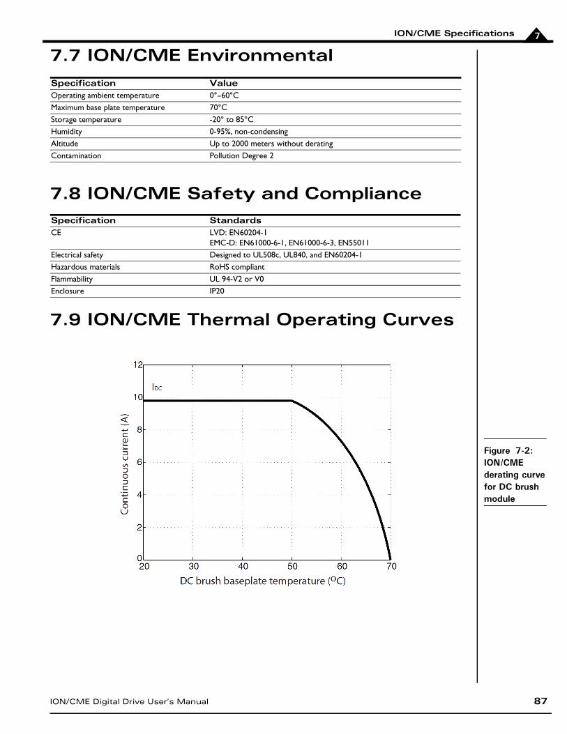
ION/CME Specifications
ION/CME Digital Drive User’s Manual 87
7
7.7 ION/CME Environmental
7.8 ION/CME Safety and Compliance
7.9 ION/CME Thermal Operating Curves
Specification ValueOperating ambient temperature 0°–60°CMaximum base plate temperature 70°CStorage temperature -20° to 85°CHumidity 0-95%, non-condensingAltitude Up to 2000 meters without deratingContamination Pollution Degree 2
Specification StandardsCE LVD: EN60204-1
EMC-D: EN61000-6-1, EN61000-6-3, EN55011Electrical safety Designed to UL508c, UL840, and EN60204-1Hazardous materials RoHS compliantFlammability UL 94-V2 or V0Enclosure IP20
Figure 7-2: ION/CME derating curve for DC brush module
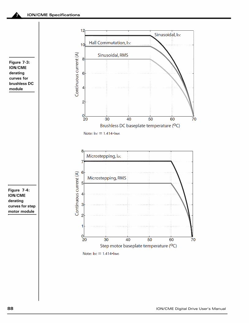
ION/CME Specifications
88 ION/CME Digital Drive User’s Manual
7
Figure 7-3: ION/CME derating curves for brushless DC module
Figure 7-4: ION/CME derating curves for step motor module
Index
ION/CME Digital Drive User’s Manual 89
Index
Symbols/Enable and FaultOut Signals 74/Enable input 30/Enable signal 75
Numerics3.3V supply monitor443-phase bridge 404-quadrant operation 40
AA and B quadrature inputs 69auxiliary encoder connector 84
pinouts 20, 84wiring 20
Auxiliary Voltage (AuxV) input 16AxisIn and AxisOut signals 24, 73
BBlock Diagram 39brushless DC motors
connection 15drive ratings 79Hall signals 20, 22phase current feedback 40power stage configuration 40
bufferstrace 44
Ccable shield. See shielded cablecircuits
auxiliary encoder input 71AxisIn 73AxisOut 74FaultOut 75Hall input 70High Speed Capture 73limit and home input 72main encoder input 69protection 83reset 44
C-Motion 28coldplate cooling method 13Comm ports 26Comm Status LED 14communication ports 40
Index
90 ION/CME Digital Drive User’s Manual
RS232/485 version 26communications
point-to-point 28ports 26status LED 30
commutation, sinusoidal 70compliance and safety specifications 87conditions
hard fault 45operational and fault 45
configurable loop modes 80connectors
auxiliary encoder 20, 84by module type 15Ethernet 26feedback 18, 83I/O 24, 84locator 14motor 17, 83power 16, 83 RJ45 26RS232/485 26serial 26
controller performance specification 80convection cooling method 13current foldback. See I2t current foldback
Ddata traces 44DC brush motors
connection 15drive ratings 79phase current feedback 40power stage configuration 40
DC bus 43current monitoring 43overvoltage and undervoltage 43
DC/DC converter 16Defaults & Limits 42Developer’s Kit 12diagrams
/Enable input circuit 75auxiliary encoder input circuits 71AxisIn circuit 73AxisOut circuit 74connector locator 14dimensions 86encoder phasing 70FaultOut circuit 75
Index
ION/CME Digital Drive User’s Manual 91
Hall Input circuit 70High Speed Capture circuit 73Limit & Home circuit 72ION/CME mounted on DIN rail 68ION/CME with heat sink attached 67main encoder input circuits 69optional DIN rail adapter 68optional heat sink 67simplified serial transceiver 40
differential encoderelectrical specifications 81outputs 20signals 69
digital inputs and outputs 76dimensions diagram 86DIN rail adapter 68
grounding and 13installation 68removing 68
disabled condition 45drive ratings 79Dual Encoder connection summary 22
Eelectrical specifications 81Enabled condition 45encoder
auxiliary 71electrical specifications 81incremental quadrature 69main 69phasing diagram 70
Encoder Connections 20environmental specifications 87
FFaultOut signal 24,74faults, hard 45feedback connector 83
pinouts 18, 83wiring 19
forced air cooling method 13frequency
PWM 40ripple current 40
Gground fault 43, 45
Index
92 ION/CME Digital Drive User’s Manual
HHall signals 20, 22, 70hard electrical faults 45hard fault state 45H-Bridge 40heat sink, mounting optional 67High Speed Capture 24, 72Home inputs 72
II/O connector
pinouts 24, 84wiring 24
I2t current foldback 41energy limit 41
incremental quadrature encoders 69index
alignment 69event 69phasing 70
inputs/Enable 30A and B quadrature 69auxiliary encoder 71digital 76Hall 70High Speed Capture 24, 73limit and home 72main encoder 69quadrature 69
installationapplying power 29communications configuration 28configuration and mounting 13connector pinouts 14DIN rail adapter 68hardware requirements 12model numbers 11software 28status LEDs 30wiring 14
Internal Logic Fault 45IO_5V 24
auxiliary encoder connector 20fault 45feedback connector 18Indexer connector 25I/O connector 24monitor 44
Index
ION/CME Digital Drive User’s Manual 93
power connector 16
LLEDs
communications (Comm) status 14hard electrical faults 45Module Status 30operational and fault modes 45
limit input 72loop rates 80
Mmain encoder input circuits 69main encoder signals 69mechanical specifications 86microstepping drive
connection 15model numbers 11modes
configurable loop 80fault 45operational 45
Module Status LED 30monitor
3.3V supply 44IO_5V 44
MOSFET power stages 40, 41motor case wire 17motor connector
applying power 29pinouts 17, 83wiring 17
Motor Feedback 69mounting
cooling methods and 13dimensions diagram 86DIN rail adapter 68mechanical specifications 86optional heat sink 67recommended surface 13
multi-drop networking 40
Nnetworking
configurations 28multi-drop 40termination 28, 29
noiseminimizing electrical 13, 17, 25, 26R-C lowpass filter 70
Index
94 ION/CME Digital Drive User’s Manual
Ooperating temperature 41orientation, recommended 13outputs
differential encoder 20digital 77single-ended 20
overcurrent fault 45overtemperature protection 41overtravel limits 24, 41overvoltage threshold 43
Ppackets, communications 30phase current feedback 41pinouts 14
auxiliary encoder connector 20, 84feedback connector 18, 83I/O connector 24, 84Indexer connector 25, 84motor connector 17, 83power connector 16, 83
point-to-point communications 28ports, communication 40Position Capture Sources 72position error tracking 80power
applying 29overvoltage threshold 43
power connectorpinouts 16, 83wiring 16
powerupmodule status LED 30
profile modes 80Pro-Motion application
CD 28protection circuits 83PWM
frequency 40ripple current 40switching scheme 40
PWM Power Stage 40
Qquadrature
A and B inputs 69encoders 20incremental encoders 69
Index
ION/CME Digital Drive User’s Manual 95
RR-C lowpass filter bandwidth
/Enable and FaultOut signals 74Hall inputs 70high speed capture input 72limit and home inputs 72
reset condition 44RJ45 connector 26RS232/485 connector
communication ports 26electrical specifications 81wiring 27
Ssafety and compliance specifications 87safety interlocks 74servo motors 40shielded cable 15
auxiliary encoder connector 20feedback connector 18I/O connector 24Indexer connector 25motor connector 17
signal connectors 83Single Encoder connection summary 20single-ended
auxiliary encoder signals 71encoder inputs 69
sinusoidal commutation 70software installation 28specifications
controller performance 80drive ratings 79electrical 81environmental 87mechanical 86safety and compliance 87
status LEDs 30step motors
automatic holding current reduction 41drive ratings 79phase current feedback 41power stage configuration 40
stub cable 63
Ttemperature sensors 41Thermal Operating Curves 87Trace Buffer 44
Index
96 ION/CME Digital Drive User’s Manual
trace capture 44trigger latency 72trigger sources 72
Uundervoltage, condition and threshold 43
Wwiring
applying power 29auxiliary encoder connector 20feedback connector 18I/O connector 24Indexer I/O 25motor connector 17power connector 16recommended auxiliary encoder 20recommended feedback 19RS232/485 wiring 27typical I/O 24typical motor 17typical power 16

ION/CME Digital Drive User’s Manual 97
For additional information or for technical assistance,please contact PMD at (978) 266-1210.
You may also e-mail your request to [email protected]
Visit our website at http://www.pmdcorp.com
Performance Motion Devices80 Central Street
Boxborough, MA 01719