Embed Size (px)
Citation preview
2017 95
Lucía González Bermúdez
Iodoethynyl derivatives scaffolds insupramolecular chemistry: the
interplay of design and synthesis
Departamento
Director/es
Química Orgánica
Uriel Rubio, SantiagoSerrano Ostáriz, José Luis
© Universidad de ZaragozaServicio de Publicaciones
ISSN 2254-7606
Director/es
Tesis Doctoral
Autor
Repositorio de la Universidad de Zaragoza – Zaguan http://zaguan.unizar.es
UNIVERSIDAD DE ZARAGOZA
Reconocimiento – NoComercial –SinObraDerivada (by-nc-nd): No sepermite un uso comercial de la obraoriginal ni la generación de obrasderivadas.

Departamento
Director/es
© Universidad de ZaragozaServicio de Publicaciones
ISSN 2254-7606
Director/es
Tesis Doctoral
Autor
Repositorio de la Universidad de Zaragoza – Zaguan http://zaguan.unizar.es
UNIVERSIDAD DE ZARAGOZA
Reconocimiento – NoComercial –SinObraDerivada (by-nc-nd): No sepermite un uso comercial de la obraoriginal ni la generación de obrasderivadas.
Departamento
Director/es
© Universidad de ZaragozaServicio de Publicaciones
ISSN 2254-7606
Lucía González Bermúdez
IODOETHYNYL DERIVATIVESSCAFFOLDS IN SUPRAMOLECULAR
CHEMISTRY: THE INTERPLAY OFDESIGN AND SYNTHESIS
Director/es
Química Orgánica
Uriel Rubio, SantiagoSerrano Ostáriz, José Luis
Tesis Doctoral
Autor
2017
Repositorio de la Universidad de Zaragoza – Zaguan http://zaguan.unizar.es
UNIVERSIDAD DE ZARAGOZA
Reconocimiento – NoComercial –SinObraDerivada (by-nc-nd): No sepermite un uso comercial de la obraoriginal ni la generación de obrasderivadas.

Departamento
Director/es
© Universidad de ZaragozaServicio de Publicaciones
ISSN 2254-7606
Director/es
Tesis Doctoral
Autor
Repositorio de la Universidad de Zaragoza – Zaguan http://zaguan.unizar.es
UNIVERSIDAD DE ZARAGOZA
Reconocimiento – NoComercial –SinObraDerivada (by-nc-nd): No sepermite un uso comercial de la obraoriginal ni la generación de obrasderivadas.
TESIS DOCTORAL
Iodoethynyl derivatives scaffolds in
supramolecular chemistry: the
interplay of design and synthesis.
Departamento de Química Orgánica
Facultad de Ciencias
Instituto de Nanociencia de Aragón
Instituto de Ciencia de los Materiales de Aragón
Universidad de Zaragoza
Memoria presentada en la Universidad de Zaragoza para optar al
grado de Doctor en Química por:
Lucía González Bermúdez
Zaragoza, Mayo 2017

INFORME DIRECTORES
Autorización de presentación de la tesis con mención internacional.
D. SANTIAGO URIEL RUBIO, Profesor Titular del Departamento de Química
Orgánica, y D. JOSÉ LUIS SERRANO OSTÁRIZ, Catedrático del Departamento
de Química Orgánica,
AUTORIZAN
La presentación de la siguiente memoria, titulada “Iodoethynyl derivatives
scaffolds in supramolecular chemistry: the interplay of design and synthesis.”,
presentada por Dña. LUCÍA GONZÁLEZ BERMÚDEZ para optar al grado de
Doctor por la Universidad de Zaragoza, y certifican que ha sido realizada bajo su
dirección en el Departamento de Química Orgánica.
Y para que conste, expiden la presente autorización
En Zaragoza, a 05 de Mayo de 2017
Fdo. Santiago Uriel Rubio Fdo. José Luis Serrano Ostáriz

TRIBUNAL DESIGNADO PARA LA DEFENSA
DOCTORANDA Dª. Lucía González Bermúdez
TÍTULO DE LA TESIS: “Iodoethynyl derivatives scaffolds in supramolecular
chemistry: the interplay of design and synthesis.”
PRESIDENTE: LARRY R. FALVELLO
SECRETARIO: GUILLERMO MÍNGUEZ ESPALLARGAS
VOCAL 1: MARC FOURMIGÉ
SUPLENTE 1: TERESA SIERRA TRAVIESO:
SUPLENTE 2: EMMA CAVERO MENÉNDEZ
El tribunal designado para calificar la tesis doctoral arriba indicada y reunido en el
día de la fecha, una vez efectuada la defensa por la doctoranda y contestadas las
objeciones y/o sugerencias que se le han formulado, ha otorgado por la calificación
de:
En Zaragoza, a de de 2017

Agradecimientos
Agradecer a mis directores de Tesis Doctoral el Dr. José Luis Serrano y el Dr.
Santiago Uriel por brindarme la oportunidad de realizar este intenso estudio de los
enlaces de halógeno dentro del grupo de Cristales Líquidos y Polímeros
perteneciente al departamento de Química Orgánica, así mismo agradecer al
Ministerio de Economía Industria y Competitividad la financiación que lo ha hecho
posible mediante la beca predoctoral FPI 2010, la estancia breve FPI 2013 con el
Dr Jagadese Jay Vittal en la Universidad de Singapur, y los proyectos MAT2009-
1436-C03-01 y MAT2012-38538-C03-01.

A mi madre

Resumen
El manuscrito de tesis se enmarca dentro del ámbito de la Química
Supramolecular, la cual fue definida por Jean Marie Lehn como “la química
más allá de la molécula”.1
Es un campo altamente interdisciplinario que cubre tanto aspectos
químicos, como físicos y biológicos, de las especies químicas de complejidad
más grande que las moléculas mismas que se mantienen unidas y
organizadas por medio de interacciones no covalentes. Uno de los aspectos
más importantes y rápidamente desarrollados de la química supramolecular
es la síntesis de cristales moleculares, la cual es también un objetivo mayor
de otra área relativamente nueva, la ingeniería cristalina. La ingeniería
cristalina se define como el estudio de las interacciones intermoleculares en
el contexto del empaquetamiento cristalino, por un lado, y como la
utilización del dicho entendimiento en el diseño de los sólidos nuevos con
las propiedades físicas y químicas deseadas, por el otro. Los cristales
moleculares, que consisten de las moléculas orgánicas, organometálicas o
de los complejos de coordinación, cuales están ensamblados en el estado
sólido como la consecuencia de las interacciones no-covalentes, son los
objetos de investigaciones numerosas durante las últimas décadas. El
interés hacia tales materiales es el resultado de la posibilidad de manipular
con las propiedades de los cristales singulares en el estado sólido a través
de la variación sistemática de sus estructuras moleculares y de las
propiedades de sus componentes moleculares.
Dentro de la química supramolecular también se encuentran los cristales
líquidos. El estado cristal líquido2 se define como un estado de agregación
de la materia intermedio entre el estado cristalino y el líquido, y surge como
consecuencia de fuerzas intermoleculares en un proceso de auto-
organización supramolecular. La inusual combinación en estos sistemas de
propiedades, como fluidez y anisotropía, han permitido que estos
materiales tengan, desde hace 50 años, una gran cantidad de aplicaciones
en la vida cotidiana (relojes, calculadoras, televisores, cosméticos, etc.). No
obstante, lo aprendido a lo largo de estos años ha permitido así mismo
constatar lo que probablemente en la actualidad suponga el mayor
atractivo, interés e innovación de los cristales líquidos: que este estado de
agregación de la materia sea considerada como una herramienta de trabajo
en la consecución de nuevos sistemas y aplicaciones.
En la última década una de las líneas de investigación del Grupo de Cristales
Líquidos y Polímeros se ha centrado en la preparación y caracterización de
nuevas materiales basados en enlaces de halógeno. Las propiedades de un
material no dependen únicamente de las moléculas que lo componen sino
también de su organización en estado sólido. Además, de las interacciones
clásicas (enlace de hidrógeno, dipolo-dipolo, enlace de coordinación) están
cobrando una gran importancia los enlaces de halógeno. Este tipo de
interacciones se ha empleado en la preparación de conductores orgánicos y
cristales líquidos ya que presentan una fuerza y direccionalidad similar a los
enlaces de hidrógeno.
OBJETIVOS Y METODOLOGÍA
Objetivos:
El trabajo que se va a desarrollar en esta Tesis Doctoral tiene como objetivo
principal estudiar y aportar nuevas posibilidades de las estructuras basadas
en enlace de halógeno en Química Supramolecular, centrando nuestra
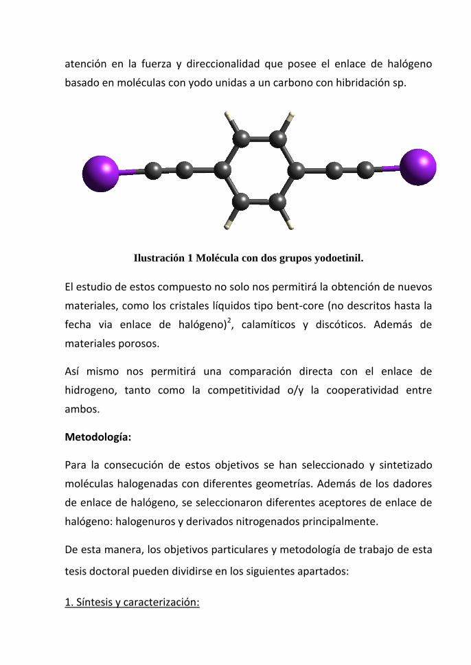
atención en la fuerza y direccionalidad que posee el enlace de halógeno
basado en moléculas con yodo unidas a un carbono con hibridación sp.
Ilustración 1 Molécula con dos grupos yodoetinil.
El estudio de estos compuesto no solo nos permitirá la obtención de nuevos
materiales, como los cristales líquidos tipo bent-core (no descritos hasta la
fecha via enlace de halógeno)2, calamíticos y discóticos. Además de
materiales porosos.
Así mismo nos permitirá una comparación directa con el enlace de
hidrogeno, tanto como la competitividad o/y la cooperatividad entre
ambos.
Metodología:
Para la consecución de estos objetivos se han seleccionado y sintetizado
moléculas halogenadas con diferentes geometrías. Además de los dadores
de enlace de halógeno, se seleccionaron diferentes aceptores de enlace de
halógeno: halogenuros y derivados nitrogenados principalmente.
De esta manera, los objetivos particulares y metodología de trabajo de esta
tesis doctoral pueden dividirse en los siguientes apartados:
1. Síntesis y caracterización:
- Síntesis y caracterización de derivados de yodoetinil ditopicos y tritopicos
con diferentes geometrías. Capítulo 1.
- Síntesis y caracterización de bases de Tröger halogenadas para formación
de redes supramoleculares porosas. Capítulo 3.
La síntesis de estos compuestos combina diferentes reacciones de
esterificación, halogenación, etc.
Todos los compuestos preparados, tanto intermedios como finales, se
caracterizarán según las técnicas habituales para determinar su estructura
química: espectroscopia de resonancia magnética nuclear de protón y de
carbono (1H-RMN y 13C-RMN), espectroscopia infrarroja (IR) y
espectrometría de masas (MS). Además se estudiarán sus propiedades en
el monocristal.
2. Estudio y caracterización de las propiedades:
- En el capítulo 4 se estudiará la formación de cocristales mediante enlaces
de halógeno como interacción principal, y los enlaces de hidrógeno como
herramientas para aumentar la dimensionalidad estructural.
- En el capítulo 5 se estudiarán las propiedades térmicas y mesomorfas de
los materiales mediante microscopía óptica con luz polarizada, calorimetría
diferencial de barrido (DSC), termogravimetría (TGA) y difracción de rayos X.
- En el capítulo 6 se sintetiza, caracteriza y estudia las propiedades de una
molécula con 4 posibilidades diferentes de interacción, además del enlace
de halógeno, hilo conductor de esta tesis, la posibilidad de coordinación
metálica, enlaces de hidrógeno o interacciones π-π.
Asimismo en el capítulo 5 y en el capítulo 4 se hará uso de otras técnicas
como espectroscopia Raman, espectroscopia fotoelectrónica de rayos X
(XPS), calorimetría isoterma de titulación (ITC), difracción de rayos X de
monocristal y de polvo para completar los estudios de cristales líquidos del
capítulo 5 y en el capítulo 4 también se pretende comparar las propiedades
en disolución con las del estado sólido, por ello el uso del ITC.
[1] J.-M. Lehn, Angewandte Chemie International Edition in English 1990, 29,
1304-1319.
[2] L. Gonzalez, N. Gimeno, R. Maria Tejedor, V. Polo, M. Blanca Ros, S. Uriel
and J. Luis Serrano, Chem. Mat. 2013, 25, 4503-4510.

Acronyms list
13C-NMR Nueclear Magnetic Resonance Carbon
1H-NMR Nueclear Magnetic Resonance Proton
1,3,5-TIEB 1,3,5-tris(iodoethynyl)benzene
1,3,5-TIPCB tris(3-iodoprop-2-yn-1-yl) benzene-1,3,5-tricarboxylate
A Halogen-hydrogen bond acceptor
Å
Angstrom (1·10-10
m)
BET Brunauer–Emmett–Teller
BPE bis(4-pyridyl)ethylene
BSSE “Basis set superposition error”
CDCl3 Cloroformo deuterado
CDS “Cambrigde structural database”
COF “Covalent-organic frameworks”
Col. Colaboradores
Colh Columnar hexagonal
Cr Cristal
DCC N,N´-diciclohexilcarbodiimida
de Distancia externa a la superficie de Hirshfeld
DFT “Density functional theory”
di Distancia interna a la superficie de Hirsfeld
DMAP 4-(dimetilamino)piridina
DMSO dimetilsulfóxido
DSC “Differential scanning calorimetry” (calorimetría diferencial de barrido)
DTMABr Deciltrimethyl Ammonium Bromide
EI Ionización electrónica
ESI Ionización por electrospray
EtOH Etanol
FT-IR espectroscopia infrarroja por transformada de Fourier
HBOF “Hydrogen bond organic frame-works”
HPLC “High-Performance Liquid Chro-matography”
HTMA hexamethylenetetramine
INPBA 4-Iodo-N-(4-pyridyl)benzamide
IUPAC “Internacional union of pure and applied chemistry”
ITC Isothermal tritation calorimetry
MALDI “Matrix-assited laser desorption ionization”
mBIEB 1,3-bis(iodoethynyl)benzene
MeOH Metanol
MOF Metal-organic frameworks
MOM Metal-organic materials
Mp “Melting point”
MS “Mass Spectrometry”
NBO “Natural bond orbital”
NPBA N-(4-pyridyl)benzamide
ORTEP “Oak Ridge Thermal Ellipsoid” Plot
pBBrEB 1,4-bis(bromoethynyl)benzene
pBIEB 1,4-bis(iodoethynyl)benzene
pBIPT bis(3-iodoprop-2-yn-1-yl) terephthalate
Ph4PBr Tetraphenyl Phosphonium bromide
POCM porous organic polymers and crystalline materials
Rac Racemic
STC “Supramolecular-tilt-chirality”
T Coordination shape
TB Tröger´s Base
TBABr Tetrabutylammonium Bromide
TFA Ácido trifluoroacético
TGA Thermogravimetry
THF Tetrahidrofurane
TPABr Tetrapropyl ammonium Bromide
TMS tetrametilsilane

INDEX
Chapter 1 Introduction ......................................................................................... 1
1.1 Bibliography ............................................................................................... 6
Chapter 2 Iodoethynyl halogen bond donors ....................................................... 7
2.1 Introduction ................................................................................................ 9
2.2 Previous works of halogen bond acceptor groups .................................... 12
2.3 Objectives ................................................................................................. 14
2.4 Synthesis of the bis-iodoethynyl synthons and their bis-ethynyl precursors
15
2.4.1 Preparation of the ethynyl precursors ................................................ 15
2.4.2 Synthesis of the iodoethynyl derivatives ........................................... 16
2.5 Ethynyl vs iodoethynyl derivatives: A comparative study. ...................... 17
2.5.1 1,4-Bis(iodoethynyl)benzene (pBIEB) vs 1,4-bis(ethynyl)benzene
(pBEB) 20
2.5.2 1,3,5-Tris(iodoethynyl)benzene (1,3,5-TIEB) vs 1,3,5-
tris(ethynyl)benzene ........................................................................................ 26
2.5.3 1,3-Bis(iodoethynyl)benzene (mBIEB) ............................................ 29
2.5.4 Bis(3-iodoprop-2-yn-1-yl) terephthalate (pBIPT) vs bispropargyl
terephthalate (pBPT) ....................................................................................... 32
2.5.5 Tris(3-iodoprop-2-yn-1-yl) benzene-1,3,5-tricarboxylate (1,3,5-
TIPCB) vs tris(prop-2-yn-1-yl) benzene-1,3,5-tricarboxylate (1,3,5-TPCB) . 34
2.6 Conclusions .............................................................................................. 38
2.7 Experimental Section ................................................................................ 39
2.7.2 General method .................................................................................. 39
2.7.3 Characterization of halogen derivatives ............................................ 40
2.7.4 X-ray monocrystal diffraction ........................................................... 40
2.7.5 Hirshfeld Surfaces ............................................................................. 41
2.8 Final Remarks ........................................................................................... 43
2.9 Bibliography.............................................................................................. 44
Chapter 3 Iodo Tröger’s Base derivatives: Towards halogen bonded porous
organic crystalline materials .................................................................................... 47
3.1 Introduction ............................................................................................... 49
3.2 Previous work ........................................................................................... 50
3.3 Objectives and planning ............................................................................ 54
3.3.1 Objectives .......................................................................................... 54
3.3.2 Planning ............................................................................................. 54
3.4 Results and discussion .............................................................................. 57
3.4.1 Preparation of the Tröger’s base derivatives ..................................... 57
3.4.2 X-ray monocrystal structures of iodo Tröger’s base derivatives ....... 57
3.5 Conclusions ............................................................................................... 65
3.6 Experimental Section ................................................................................ 66
3.6.1 Synthesis and chemical characterization ........................................... 66
3.6.2 X-ray monocrystal diffraction ........................................................... 67
3.7 Bibliography.............................................................................................. 69
Chapter 4 Supramolecular chemistry: Crystal engineering ................................ 71
4.1 Introduction ............................................................................................... 73
4.2 Objectives and work plan .......................................................................... 76
4.3 Halogen bonding cocrystals ...................................................................... 77
4.3.1 Previous works .................................................................................. 77
4.3.2 X-ray Crystal Structures .................................................................... 82
4.3.3 Halogen bonded complexes 1 and 2: Linear XB donor and acceptor 88
4.3.4 Angular polymers .............................................................................. 89
4.3.5 Hirshfeld Surface Analysis ................................................................ 97
4.3.6 DFT Calculations. ............................................................................. 98
4.4 Halogen bonding salts ............................................................................ 102
4.4.1 Previous works ................................................................................ 102
4.4.2 X-ray Crystal Structures .................................................................. 107
4.4.3 pBIEB· TPABr complex, Structure 9. ........................................... 111
4.4.4 pBIEB ·TBA Br complex, Structure 10. ........................................ 113
4.4.5 pBIEB ·[TPhPBr]2 complex, Structure 11. ..................................... 115
4.4.6 Hirshfeld Surface. ............................................................................ 117
4.4.7 Isothermal Titration Calorimetry. ................................................... 122
4.5 Conclusions ............................................................................................ 127
4.6 Experimental ........................................................................................... 128
4.6.1 Crystal synthesis and characterization ............................................ 128
4.6.2 X-ray monocrystal diffraction. ........................................................ 128
4.7 Hirshfeld Surfaces .................................................................................. 131
4.8 Computational Methods. ........................................................................ 132
4.9 Bibliography ........................................................................................... 133
Chapter 5 Liquid Crystals: Promesogenic Calamitic, Bent-core and Discotic
Shapes by Halogen Bonding. ................................................................................ 139
5.1 Introduction ............................................................................................. 141
5.2 Previous works ........................................................................................ 143
5.2.1 Liquid crystals: Properties and classification .................................. 144
5.2.2 Liquid Crystal Characterization ....................................................... 149
5.2.3 Liquid crystals by hydrogen bonding .............................................. 150
5.2.4 Liquid crystals by halogen bonding ................................................. 151
5.3 Objectives and planning work................................................................. 153
5.3.1 Objectives ........................................................................................ 153
5.3.2 Planned work ................................................................................... 153
5.4 Synthesis and Characterization of the precursors and the complexes .... 157
5.4.1 General Synthesis ............................................................................ 157
5.4.2 Characterization ............................................................................... 158
5.5 Liquid crystal properties of the complexes ............................................. 167
5.5.1 Series P (rod-like structures) ........................................................... 170
5.5.2 Series M (bent-shaped structures) ................................................... 171
5.5.3 Series T (disc-like structures) .......................................................... 174
5.6 Crystal and Molecular Structure ............................................................. 177
5.7 Theoretical modeling .............................................................................. 180
5.8 Conclusions ............................................................................................. 182
5.9 Eperimental Section ................................................................................ 183
5.9.1 Synthesis .......................................................................................... 183
5.9.2 Computational methods ................................................................... 186
5.9.3 X-ray monocrystal diffraction ......................................................... 187
5.10 Bibliography ........................................................................................ 189
Chapter 6 Coordination Metal Complexes Based on 4-Iodo-N-(4-
pyridyl)benzamide, a Polyfunctional Ligand ........................................................ 193
6.1 Introduction. ........................................................................................... 195
6.2 Previous works ....................................................................................... 197
6.3 X-ray Crystallography ............................................................................ 202
6.3.1 4-iodo-N-(4-pyridyl)benzamide (INPBA). ..................................... 202
6.4 Hirshfeld Surface Analysis ..................................................................... 213
6.5 Quantum Mechanical Calculations ......................................................... 215
6.6 Conclusions ............................................................................................ 217
6.7 Experimental Section .............................................................................. 218
6.8 Bibliography ........................................................................................... 222
Chapter 7 Conclusions ..................................................................................... 225

Chapter 1 Introduction

Chapter 1 3
Non-covalent interactions have become an extraordinary and versatile tool to
generate many original and attractive supramolecular architectures and
functionalities in different fields.[1]
Among them, it is worth highlighting the remarkable evolution of hydrogen
bonding from being a curious intermolecular interaction between a hydrogen atom
and an electron-rich partner to being a powerful tool for molecular control of
protein and DNA chemistry, crystal engineering of solid-state materials and also in
soft matter assemblies. Regarding soft materials, the use of hydrogen bonding is
quite widespread in the field liquid crystals, and crystals engineering in which it
has been successfully used to prepare a varied of functional materials.[2]
In this context, an alternative working strategy to hydrogen bonding (HB) is
halogen bonding (XB). Indeed, a great deal of research has recently been carried
out with the aim of understanding and harnessing this type of noncovalent
interaction, which involves pairing a halogen atom with an electron-rich partner.
Although the halogen bond was described more than 150 years ago,[3]
it was not
until the 1970s that O.Hassel highlighted the ability of this interaction to manage
self-assembly processes.[4]
During the past decade, many applications of halogen
bonding in fields as diverse as crystal engineering, enantiomer separation, biology,
and supermolecular architectures have been reported and reviewed.[5]
This
noncovalent interaction exhibits similar characteristics to HB in directionality and
strength and may cooperate with or prevail over HB.[6]
In the work recovered in this PhD we tried to advance in the knowledge
supramolecular organizations based of the XB and other weak interactions. Among
the different structural possibilities to introduce XB bonds we have choose the
iodoethynyl group as the main halogen bond donor group because their novelty and
their excellent geometrical and electronic properties.
Introduction 4
Thus the chapter 2 is devoted to the new Iodoethynyl halogen bond donor
molecules designed and synthesized in this PhD. In the synthesis of these
compounds the homologous precursors bearing ethynyl moieties instead the
iodoethynyl groups are obtained. Both type of compounds form in the solid state to
give rise to very interesting isostructural crystalline organizations. A comparative
study of these structures has been made.
Chapter 3 is devoted to preparation of porous organic crystalline materials. In order
to achieve this objective we are choose Iodo-containing Tröger base derivatives
functionalized in positions 2 and 8, taking advantage of their rigid geometry and
self−complementarity of their enantiomers in racemic mixtures.
In chapter 4 deals with crystal engineering procedures to guide the arrangement
adopted by the individual molecules in the solid networks. In our case we use the
cocrystallization of two or more components that engage via weak interactions as
hydrogen or halogen bond, π···π staking or a combination of them. This strategy
allows obtaining new architectures in a versatile way using previously described
compounds.
Chapter 5 is devoted to prepare new ‘supermolecules’ by means of halogen
bonding interactions that exhibit liquid crystal properties. Our approach combine
halogen bond donors based on bis(iodoethynyl)benzene derivatives and halogen
bond acceptors based on basic nitrogen-containing molecules. In order to advance
in the knowledge of the liquid crystal state a study of the structure-activity
relationship for the complexes have been planned.
Finally chapter 6 explored the design of solid state structures based on molecules
that use metal-ligand coordination, hydrogen and halogen bonding, and -
stacking interactions as directional motifs to guide the self-assembly of network
structures. One of the most powerful strategies for regulating solid-state structure is
the arrangement of metallotectons by non-covalent interactions. However, the
Chapter 1 5
presence of halogen bonding in metal coordination polymers has not been received
sufficient attention.[7]
Introduction 6
1.1 Bibliography
[1] a) J. Ř. P. Hobza, Chem. Rev. 2016, 9, 11; b) A. S. M. a. G. N. Sastry, Chem. Rev. 2016, 116,
2775–2825; c) M. Raynal, P. Ballester, A. Vidal-Ferran and P. W. van Leeuwen, Chem Soc Rev
2014, 43, 1660-1733; d) K. T. M. A. M. Maharramov, M. N. Kopylovich, A. J. L. Pombeiro,, Non-
covalent Interactions in the Synthesis and Design of New Compounds, Wiley, 2016, p.
[2] a) M. Meot-Ner., Chem. Rev 2011, 110, 22-103; b) M. B. G. Armstrong, J Mat. Sci. 2005, 40,
547-559; c) M. I.-V. E. D. Głowacki, S. Bauer, N. S. Sariciftci, , J. Mater. Chem. B 2013, 1, 3742-
3753; d) T. Steiner, Angew. Chem., Int. Ed. 2002, 41, 48.
[3] a) F. Guthrie, J. Chem. Soc. 1863, 16, 239; b) I. N. Remses, J. F. , Am. Chem. J. 1896, 18, 90.
[4] a) O. Hassel and J. Hvoslef, Acta Chemica Scandinavica 1954, 8, 873-873; b) O. Hassel and C.
Romming, Quarterly Rev. 1962, 16, 1-18; c) H. A. Bent, Chem. Rev. 1968, 68, 587.
[5] a) P. Auffinger, F. A. Hays, E. Westhof and P. S. Ho, Proc. Natl. Acad. Sci. U. S. A. 2004, 101,
16789; b) P. Metrangolo, H. Neukirch, T. Pilati and G. Resnati, Acc. Chem. Res. 2005, 38, 386-395;
c) A. R. Voth and P. S. Ho, Curr. Top. Med. Chem. 2007, 7, 1336; d) P. Metrangolo, F. Meyer, T.
Pilati, G. Resnati and G. Terraneo, Angew. Chem., Int. Ed. 2008, 47, 6114; e) D. W. Bruce in
Halogen-bonded liquid crystals, Vol. 126 Eds.: P. Metrangolo and G. Resnati), 2008, pp. 161-180;
f) L. A. Hardegger, B. Kuhn, B. Spinnler, L. Anselm, R. Ecabert, M. Stihle, B. Gsell, R. Thoma, J.
Diez, J. Benz, J. M. Plancher, G. Hartmann, D. W. Banner, W. Haap and F. Diederich, Angew Chem
Int Ed Engl 2011, 50, 314-318; g) H. L. Nguyen, P. N. Horton, M. B. Hursthouse, A. C. Legon and
D. W. Bruce, J. Am. Chem. Soc. 2004, 126, 16; h) M. Fourmigue and P. Batail, Chem. Rev. 2004,
104, 5379-5418; i) L. C. Gilday, S. W. Robinson, T. A. Barendt, M. J. Langton, B. R. Mullaney and
P. D. Beer, Chem. Rev. 2015, 115, 7118-7195.
[6] I. I. Ebralidze, M. Hanif, R. Arjumand, A. A. Azmi, D. Dixon, N. M. Cann, C. M. Crudden and
J. H. Horton, J. Phys. Chem. C 2012, 116, 4217.
[7] a) L. Brammer, G. M. Espallargas and S. Libri, CrystEngComm 2008, 10, 1712-1727; b) R.
Bertani, P. Sgarbossa, A. Venzo, F. Lelj, M. Amati, G. Resnati, T. Pilati, P. Metrangolo and G.
Terraneo, Coord. Chem. Rev. 2010, 254, 677; c) R. Bertani, P. Sgarbossa, A. Venzo, F. Lelj, M.
Amati, G. Resnati, T. Pilati, P. Metrangolo and G. Terraneo, Coord. Chem. Rev. 2010, 254, -
d) . . Troff, T. M kel , . Topic , A. Valkonen, K. Raatikainen and K. Rissanen, Eur. J.
Org. Chem. 2013, 2013, 1617; e) B. Li, S.-Q. Zang, L.-Y. Wang and T. C. W. Mak, Coord. Chem.
Rev. 2016, 308, 1-21.
Chapter 2 Iodoethynyl halogen
bond donors

Chapter 2 9
2.1 Introduction
This chapter is devoted to the synthesis and crystal structures of the iodoethynyl
derivatives, which were used throughout the work reported here as halogen
bonding donors to prepare different kinds of materials.
The first logical step in a planning such a study is to carry out a literature survey in
the area of interest. For this reason, section 2.3 of this chapter is devoted to a brief
discussion of the prior art on the different groups of halogen bond donors reported
to date. Only a few papers dealing with iodoethynyl groups were found in the
literature, despite the fact that the iodoethynyl group shows excellent properties as
a halogen bond donor.[1]
On the basis of these precedents the iodoethynyl group
was selected for the work described in this Ph.D. thesis.
As explained in chapter 1, one of the fundamental objectives of this work was to
use halogen bonding interactions as a tool to obtain supramolecular structures in
both the solid state (by crystal engineering) and in the liquid crystalline state.
In order to achieve these objectives, the design and synthesis of five ditopic tectons
bearing two iodoethynyl groups were planned. Some of these halogen bond donors
have been described previously by other authors but many of the compounds are
novel and were synthesized for the first time in this study.[2]
When selecting the appropriate synthons both the electronic parameters, such as
conjugation in the molecules, and structural factors, such as rigidity and geometry,
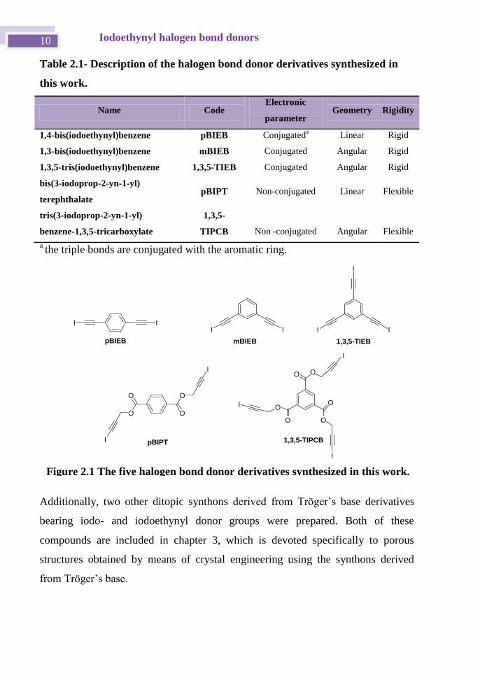
were taken into account. The three bis-iodoethynyl and the two tris-iodoethynyl
derivatives chosen for this work are shown in Table 2.1 and Figure 2.1.
Some of these difunctional building blocks have been used in the work described in
chapter 4, which concerns supramolecular crystalline structures, and in the chapter
devoted to liquid crystals.
Iodoethynyl halogen bond donors 10
Table 2.1- Description of the halogen bond donor derivatives synthesized in
this work.
Name Code Electronic
parameter Geometry Rigidity
1,4-bis(iodoethynyl)benzene pBIEB Conjugateda
Linear Rigid
1,3-bis(iodoethynyl)benzene mBIEB Conjugated Angular Rigid
1,3,5-tris(iodoethynyl)benzene 1,3,5-TIEB Conjugated Angular Rigid
bis(3-iodoprop-2-yn-1-yl)
terephthalate pBIPT Non-conjugated Linear Flexible
tris(3-iodoprop-2-yn-1-yl)
benzene-1,3,5-tricarboxylate
1,3,5-
TIPCB Non -conjugated Angular Flexible
a the triple bonds are conjugated with the aromatic ring.
Additionally, two other ditopic synthons derived from Tröger’s base derivatives
bearing iodo- and iodoethynyl donor groups were prepared. Both of these
compounds are included in chapter 3, which is devoted specifically to porous
structures obtained by means of crystal engineering using the synthons derived
from Tröger’s base.
O
O
OO
O
O
I
I
I
O
OO
O
I
I
III I I I
I
pBIEB mBIEB
pBIPT 1,3,5-TIPCB
1,3,5-TIEB
Figure 2.1 The five halogen bond donor derivatives synthesized in this work.
Chapter 2 11
The five ditopic synthons included in this chapter have halogen bond donor and
acceptor groups in their structure. These groups interact in the solid state to give
rise to very interesting structures. It is worth noting that in the synthesis of these
compounds the ethynyl derivatives are the precursors. The latter compounds also
form crystal structures that are isostructural with their related iodoethynyl
derivatives. Due to the rarity of the phenomenon of isostructuralism in crystal
engineering, a comparative study of these crystal structures could be very
attractive.
Iodoethynyl halogen bond donors 12
2.2 Previous works of halogen bond acceptor groups
As mentioned in the previous chapter, the first report dealing with halogen bonds
was published in 1863. The paper by Frederick Guthrie[3]
concerns NH3···I2 and
pyridine···alkyl iodide adducts. However, it was not until 1994 that halogen bonds
were defined for the first time by Muller.[4]
All of the studies in this field were
carried out with molecular halogens until 1968, when Bent introduced some
halogenated organic compounds.[5]
With a focus on supramolecular chemistry, and more specifically crystal
engineering, it became clear that it was possible to design and fine-tune the
structural and functional features of self-assembled adducts by selecting the nature
and the structure of the molecules involved in XB formation. The appropriate
design of halo-organic molecules with good electron-withdrawing groups increased
the atom polarizability and directionality of the halogen bond donor. In this respect,
in the 1990s the studies by Politzer and Murray were particularly significant and
they demonstrated the anisotropic charge distribution on halogen atoms that form
one covalent bond.[6]
In the 2000s the studies by Metrangolo et al. concerned the
intermolecular interaction involving a representative halogen bond acceptor
(ammonia) and halofluoromethanes by quantum chemical calculations (DFT and
MP2). The energy values and the defined geometry of the interaction promised to
make halogen bonding a very effective tool in the manipulation of
haloperfluorocarbons.[7]
It seems clear that in the last 20 years almost all of the
studies on halogen bonds are on perfluorocarbons.[8]
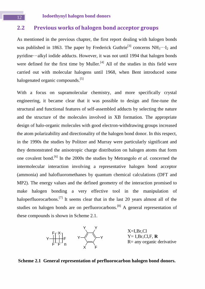
A general representation of
these compounds is shown in Scheme 2.1.
Scheme 2.1 General representation of perfluorocarbon halogen bond donors.
Y
F
F X
F
F
X
Y
Y Y
Y
Fn
X=I,Br,Cl
Y= I,Br,Cl,F, R
R= any organic derivative
Chapter 2 13
Despite the presence of electron-withdrawing groups in halocarbons, the ipso
carbon hybridization also increases the polarizability of halogen atom. Of particular
interest in this respect are the iodoethynyl groups, which are present in 1,4-
bis(iodoethynyl)benzene (pBIB) and have only been investigated by Yamamoto et
al.[9]
and Batail et al.[10]
in electrocrystallization experiments with non-halogenated
tetrathiafulvalene derivatives.
Other diodoalkynes that have been studied as halogen bond donors are
iodoacetylene[11]
and polyiodoacetylene.[12]
However, compared to these
compounds pBIB is easier to prepare and is also more stable. More recently,
Aakeröy et al. tried to establish a halogen bond donor ranking based on calculated
molecular electrostatic potential surfaces (MEPS).[13]
It was found that 1-
iodoethnyl-iodobenzene (IEIB) and 1,4-diiodotetrafluorobenzene (DITFB) are
halogen bond donors of equal strength.[13]
[14]
In the next chapter we will discuss the halogen bond donor capabilities of
bisiodoethynyl derivatives.
Iodoethynyl halogen bond donors 14
2.3 Objectives
Taking into account the information outlined above, the main objectives covered in
this chapter are:
The synthesis and characterization of the crystalline structures of the five bis-
iodoethynyl halogen bond acceptors and their bis-ethynyl precursors.
The comparative study of the crystal structures obtained with each pair of
isostructural bis-iodoethynyl and bis-ethynyl derivatives.
Chapter 2 15
2.4 Synthesis of the bis-iodoethynyl synthons and their bis-
ethynyl precursors
A general discussion of the synthetic procedures for both bis- and tris-iodoethynyl
and their bis-/tris-ethynyl precursors is included in this chapter. The detailed
procedures for the synthesis and characterization of each compound are included in
the experimental section.
2.4.1 Preparation of the ethynyl precursors
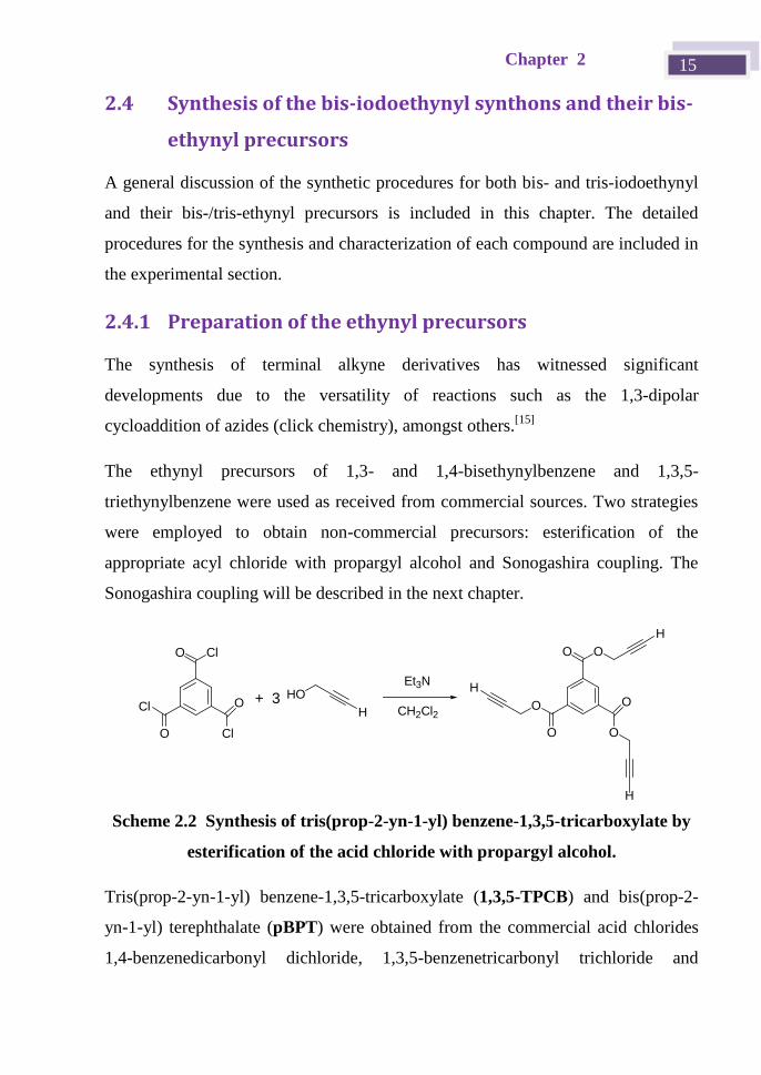
The synthesis of terminal alkyne derivatives has witnessed significant
developments due to the versatility of reactions such as the 1,3-dipolar
cycloaddition of azides (click chemistry), amongst others.[15]
The ethynyl precursors of 1,3- and 1,4-bisethynylbenzene and 1,3,5-
triethynylbenzene were used as received from commercial sources. Two strategies
were employed to obtain non-commercial precursors: esterification of the
appropriate acyl chloride with propargyl alcohol and Sonogashira coupling. The
Sonogashira coupling will be described in the next chapter.
O
O
O
O
O
O
H
H
H
O
O
O
Cl
Cl
Cl
HO
H
Et3N
CH2Cl2+ 3
Scheme 2.2 Synthesis of tris(prop-2-yn-1-yl) benzene-1,3,5-tricarboxylate by
esterification of the acid chloride with propargyl alcohol.
Tris(prop-2-yn-1-yl) benzene-1,3,5-tricarboxylate (1,3,5-TPCB) and bis(prop-2-
yn-1-yl) terephthalate (pBPT) were obtained from the commercial acid chlorides
1,4-benzenedicarbonyl dichloride, 1,3,5-benzenetricarbonyl trichloride and
Iodoethynyl halogen bond donors 16
benzenedicarbonyl dichloride by reaction with propargyl alcohol in
dichloromethane and triethylamine with yields of around 90% obtained (See
Scheme 2.2).[16]
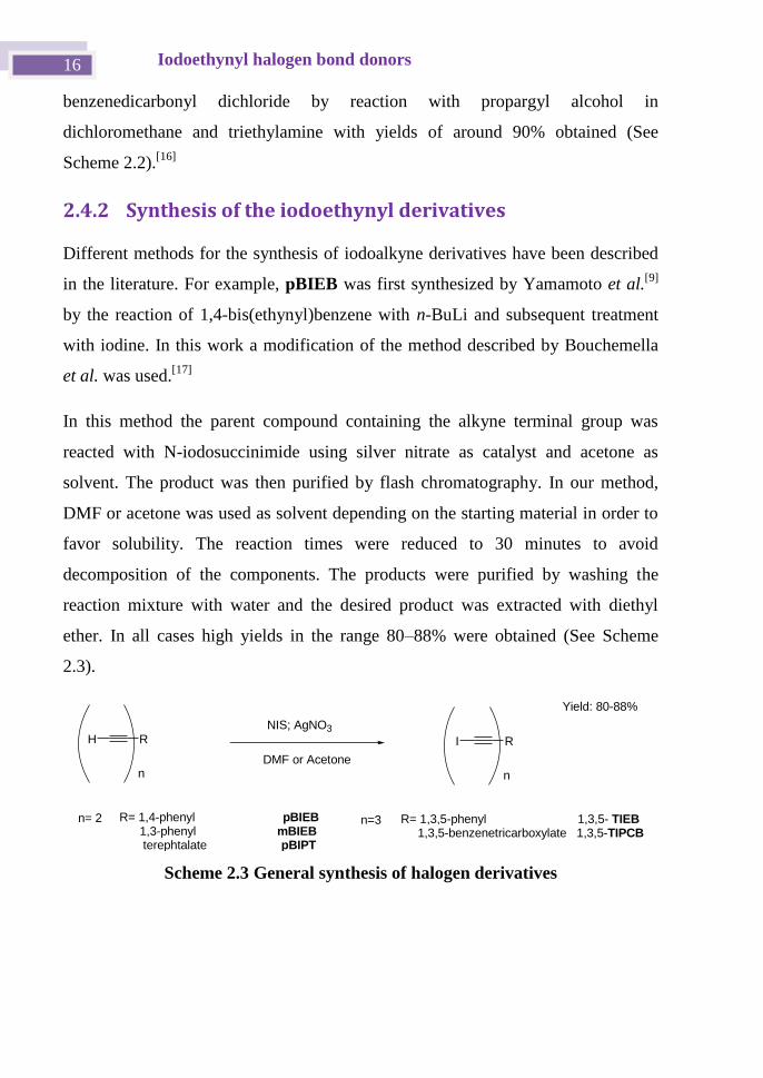
2.4.2 Synthesis of the iodoethynyl derivatives
Different methods for the synthesis of iodoalkyne derivatives have been described
in the literature. For example, pBIEB was first synthesized by Yamamoto et al.[9]
by the reaction of 1,4-bis(ethynyl)benzene with n-BuLi and subsequent treatment
with iodine. In this work a modification of the method described by Bouchemella
et al. was used.[17]
In this method the parent compound containing the alkyne terminal group was
reacted with N-iodosuccinimide using silver nitrate as catalyst and acetone as
solvent. The product was then purified by flash chromatography. In our method,
DMF or acetone was used as solvent depending on the starting material in order to
favor solubility. The reaction times were reduced to 30 minutes to avoid
decomposition of the components. The products were purified by washing the
reaction mixture with water and the desired product was extracted with diethyl
ether. In all cases high yields in the range 80–88% were obtained (See Scheme
2.3).
H
n= 2 R= 1,4-phenyl pBIEB 1,3-phenyl mBIEB terephtalate pBIPT
n=3 R= 1,3,5-phenyl 1,3,5- TIEB 1,3,5-benzenetricarboxylate 1,3,5-TIPCB
NIS; AgNO3
DMF or Acetone
Yield: 80-88%
R
n
I R
n
Scheme 2.3 General synthesis of halogen derivatives
Chapter 2 17
2.5 Ethynyl vs iodoethynyl derivatives: A comparative
study.
In this section, the crystal structures of the iodoethynyl derivatives are compared
with those of their alkyne precursors. X-ray quality single crystals were obtained
by slow evaporation of solutions of the compounds in the appropriate solvent.
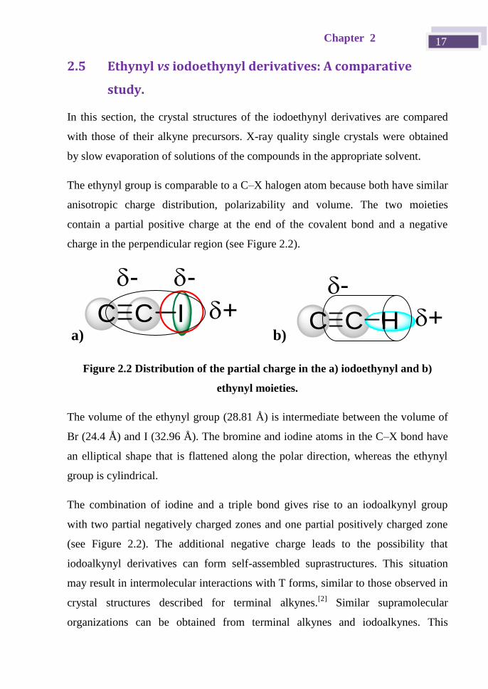
The ethynyl group is comparable to a C–X halogen atom because both have similar
anisotropic charge distribution, polarizability and volume. The two moieties
contain a partial positive charge at the end of the covalent bond and a negative
charge in the perpendicular region (see Figure 2.2).
a)
C C I
--
+ b)
C C H
-
+
Figure 2.2 Distribution of the partial charge in the a) iodoethynyl and b)
ethynyl moieties.
The volume of the ethynyl group (28.81 Å) is intermediate between the volume of
Br (24.4 Å) and I (32.96 Å). The bromine and iodine atoms in the C–X bond have
an elliptical shape that is flattened along the polar direction, whereas the ethynyl
group is cylindrical.
The combination of iodine and a triple bond gives rise to an iodoalkynyl group
with two partial negatively charged zones and one partial positively charged zone
(see Figure 2.2). The additional negative charge leads to the possibility that
iodoalkynyl derivatives can form self-assembled suprastructures. This situation
may result in intermolecular interactions with T forms, similar to those observed in
crystal structures described for terminal alkynes.[2]
Similar supramolecular
organizations can be obtained from terminal alkynes and iodoalkynes. This
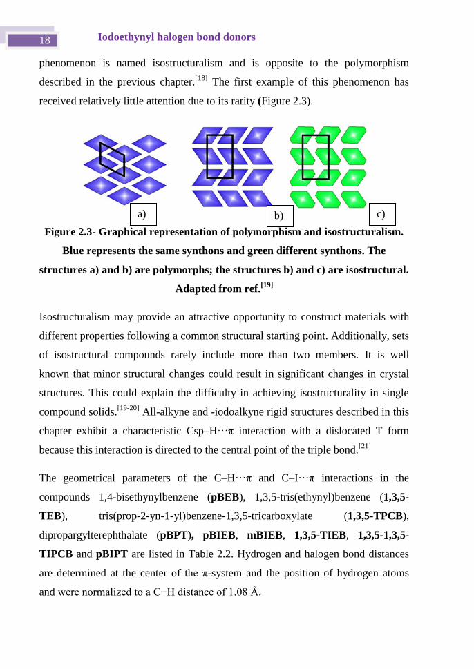
Iodoethynyl halogen bond donors 18
phenomenon is named isostructuralism and is opposite to the polymorphism
described in the previous chapter.[18]
The first example of this phenomenon has
received relatively little attention due to its rarity (Figure 2.3).
Figure 2.3- Graphical representation of polymorphism and isostructuralism.
Blue represents the same synthons and green different synthons. The
structures a) and b) are polymorphs; the structures b) and c) are isostructural.
Adapted from ref.[19]
Isostructuralism may provide an attractive opportunity to construct materials with
different properties following a common structural starting point. Additionally, sets
of isostructural compounds rarely include more than two members. It is well
known that minor structural changes could result in significant changes in crystal
structures. This could explain the difficulty in achieving isostructurality in single
compound solids.[19-20]
All-alkyne and -iodoalkyne rigid structures described in this
chapter exhibit a characteristic Csp–H···π interaction with a dislocated T form
because this interaction is directed to the central point of the triple bond.[21]
The geometrical parameters of the C–H···π and C–I···π interactions in the
compounds 1,4-bisethynylbenzene (pBEB), 1,3,5-tris(ethynyl)benzene (1,3,5-
TEB), tris(prop-2-yn-1-yl)benzene-1,3,5-tricarboxylate (1,3,5-TPCB),
dipropargylterephthalate (pBPT), pBIEB, mBIEB, 1,3,5-TIEB, 1,3,5-1,3,5-
TIPCB and pBIPT are listed in Table 2.2. Hydrogen and halogen bond distances
are determined at the center of the π-system and the position of hydrogen atoms
and were normalized to a C−H distance of 1.08 Å.
a) b) c)
Chapter 2 19
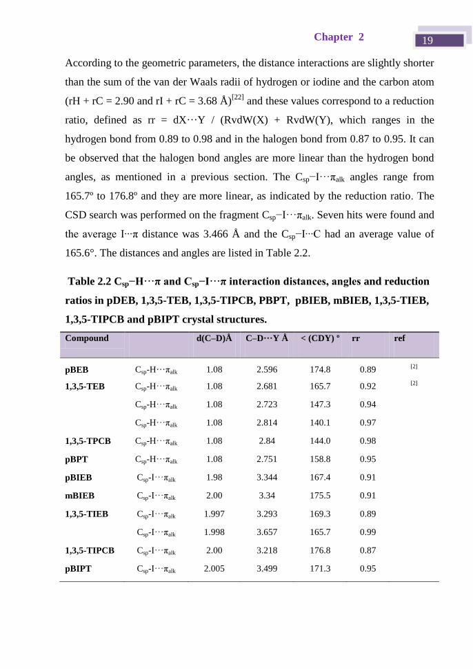
According to the geometric parameters, the distance interactions are slightly shorter
than the sum of the van der Waals radii of hydrogen or iodine and the carbon atom
(rH + rC = 2.90 and rI + rC = 3.68 Å)[22]
and these values correspond to a reduction
ratio, defined as rr = dX···Y / (RvdW(X) + RvdW(Y), which ranges in the
hydrogen bond from 0.89 to 0.98 and in the halogen bond from 0.87 to 0.95. It can
be observed that the halogen bond angles are more linear than the hydrogen bond
angles, as mentioned in a previous section. The Csp−I···πalk angles range from
165.7º to 176.8º and they are more linear, as indicated by the reduction ratio. The
CSD search was performed on the fragment Csp−I···πalk. Seven hits were found and
the average I∙∙∙π distance was 3.466 Å and the Csp−I∙∙∙C had an average value of
165.6°. The distances and angles are listed in Table 2.2.
Table 2.2 Csp−H···π and Csp−I···π interaction distances, angles and reduction
ratios in pDEB, 1,3,5-TEB, 1,3,5-TIPCB, PBPT, pBIEB, mBIEB, 1,3,5-TIEB,
1,3,5-TIPCB and pBIPT crystal structures.
Compound d(C–D)Å C–D···Y Å < (CDY) º rr ref
pBEB Csp-H···πalk 1.08 2.596 174.8 0.89 [2]
1,3,5-TEB Csp-H···πalk 1.08 2.681 165.7 0.92 [2]
Csp-H···πalk 1.08 2.723 147.3 0.94
Csp-H···πalk 1.08 2.814 140.1 0.97
1,3,5-TPCB Csp-H···πalk 1.08 2.84 144.0 0.98
pBPT Csp-H···πalk 1.08 2.751 158.8 0.95
pBIEB Csp-I···πalk 1.98 3.344 167.4 0.91
mBIEB Csp-I···πalk 2.00 3.34 175.5 0.91
1,3,5-TIEB Csp-I···πalk 1.997 3.293 169.3 0.89
Csp-I···πalk 1.998 3.657 165.7 0.99
1,3,5-TIPCB Csp-I···πalk 2.00 3.218 176.8 0.87
pBIPT Csp-I···πalk 2.005 3.499 171.3 0.95
Iodoethynyl halogen bond donors 20
The energy difference between the Csp−H···πalk hydrogen bond and the Csp−I···πalk
halogen bond was evaluated by carrying out theoretical calculations on the stability
energy of the T form (Csp−I···πalk) interaction in the pBIEB structure. A value of
5.1 kcal/mol was obtained and this is approximately four times higher than the
stabilization energy described previously (1.23 kcal/mol) for pBEB.[21a]
This result
is significantly different from the effect of alkyne and iodoalkyne groups. For
example, terminal alkynes behave as weak acids (pKa ≈ 2 ) and are poor hydrogen
bond donors, whereas iodoalkynes are very good halogen bond donors.
In the following sections, the crystal structures of iodoethynyl derivative as
halogen bond donors are compared with the precursor alkynes and the spatial
arrangements of each pair will be discussed.
2.5.1 1,4-Bis(iodoethynyl)benzene (pBIEB) vs 1,4-
bis(ethynyl)benzene (pBEB)
The structures from the first pair pBEB[2]
and pBIEB[23]
were solved in the
different spatial groups P21/c and P21/n, respectively. The spatial arrangements of
the rigid planar pairs 1,4-bis(ethynyl)benzene (pBEB)/1,4-bis(iodoethynyl)benzene
and 1,3,5-triethynylbenzene/1,3,5-tris(iodoethynyl-benzene) are isostructural. The
molecules in pBEB[2]
and pBIEB crystal structures are connected by C−H···π
hydrogen bonds and C−I···π halogen bonds, respectively, in a zig-zag pattern. Each
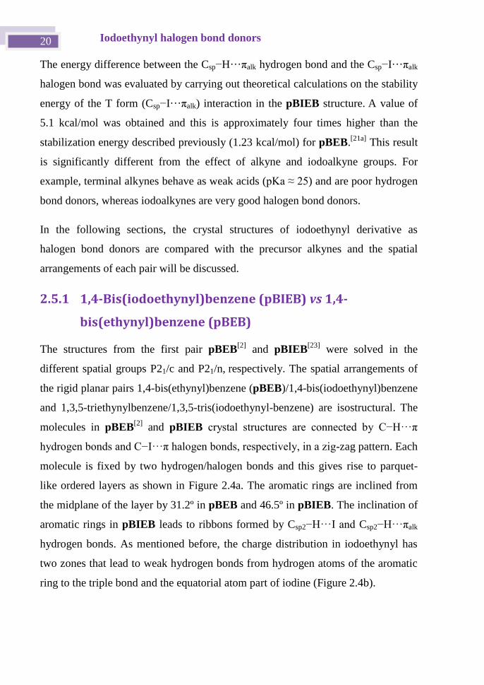
molecule is fixed by two hydrogen/halogen bonds and this gives rise to parquet-
like ordered layers as shown in Figure 2.4a. The aromatic rings are inclined from
the midplane of the layer by 31.2º in pBEB and 46.5º in pBIEB. The inclination of
aromatic rings in pBIEB leads to ribbons formed by Csp2−H···I and Csp2−H···πalk
hydrogen bonds. As mentioned before, the charge distribution in iodoethynyl has
two zones that lead to weak hydrogen bonds from hydrogen atoms of the aromatic
ring to the triple bond and the equatorial atom part of iodine (Figure 2.4b).
Chapter 2 21
Figure 2.4- Comparison of halogen−hydrogen structures in a) pBEB and b)
pBIEB.
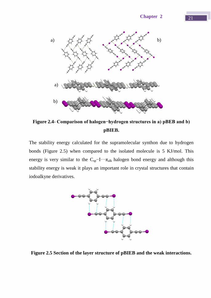
The stability energy calculated for the supramolecular synthon due to hydrogen
bonds (Figure 2.5) when compared to the isolated molecule is 5 KJ/mol. This
energy is very similar to the Csp−I···πalk halogen bond energy and although this
stability energy is weak it plays an important role in crystal structures that contain
iodoalkyne derivatives.
Figure 2.5 Section of the layer structure of pBIEB and the weak interactions.
a) b)
a)
b)
Iodoethynyl halogen bond donors 22
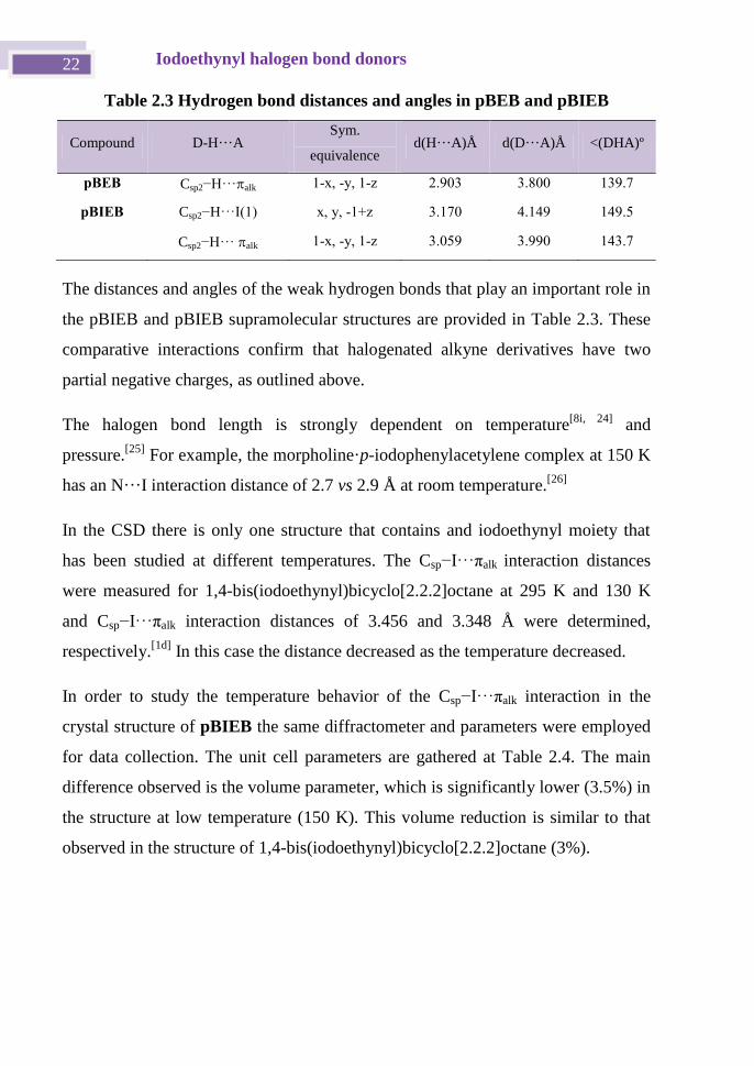
Table 2.3 Hydrogen bond distances and angles in pBEB and pBIEB
Compound D-H···A Sym.
equivalence d(H···A)Å d(D···A)Å <(DHA)º
pBEB Csp2−H···alk 1-x, -y, 1-z 2.903 3.800 139.7
pBIEB Csp2−H···I(1) x, y, -1+z 3.170 4.149 149.5
Csp2−H···alk 1-x, -y, 1-z 3.059 3.990 143.7
The distances and angles of the weak hydrogen bonds that play an important role in
the pBIEB and pBIEB supramolecular structures are provided in Table 2.3. These
comparative interactions confirm that halogenated alkyne derivatives have two
partial negative charges, as outlined above.
The halogen bond length is strongly dependent on temperature[8i, 24]
and
pressure.[25]
For example, the morpholine·p-iodophenylacetylene complex at 150 K
has an N···I interaction distance of 2.7 vs 2.9 Å at room temperature.[26]
In the CSD there is only one structure that contains and iodoethynyl moiety that
has been studied at different temperatures. The Csp−I···πalk interaction distances
were measured for 1,4-bis(iodoethynyl)bicyclo[2.2.2]octane at 295 K and 130 K
and Csp−I···πalk interaction distances of 3.456 and 3.348 Å were determined,
respectively.[1d]
In this case the distance decreased as the temperature decreased.
In order to study the temperature behavior of the Csp−I···πalk interaction in the
crystal structure of pBIEB the same diffractometer and parameters were employed
for data collection. The unit cell parameters are gathered at Table 2.4. The main
difference observed is the volume parameter, which is significantly lower (3.5%) in
the structure at low temperature (150 K). This volume reduction is similar to that
observed in the structure of 1,4-bis(iodoethynyl)bicyclo[2.2.2]octane (3%).
Chapter 2 23
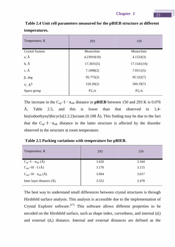
Table 2.4 Unit cell parameters measured for the pBIEB structure at different
temperatures.
Temperature, K 293 150
Crystal System Monoclinic Monoclinic
a, Å 4.23910(10) 4.1533(3)
b, Å 17.3031(5) 17.1541(16)
c, Å 7.1008(2) 7.0511(5)
, deg 95.775(2) 95.332(7)
V, Å3 518.20(2) 500.19(7)
Space group P21/n P21/n
The increase in the Csp−I···πalk distance in pBIEB between 150 and 293 K is 0.076
Å, Table 2.5, and this is lower than that observed in 1,4-
bis(iodoethynyl)bicyclo[2.2.2]octane (0.108 Å). This finding may be due to the fact
that the Csp−I···πalk distance in the latter structure is affected by the disorder
observed in the structure at room temperature.
Table 2.5 Packing variations with temperature for pBIEB.
Temperature, K 293 150
Csp−I···πalk (Å) 3.420 3.344
Csp2−H···I (Å) 3.176 3.115
Csp2−H···πalk (Å) 3.094 3.017
Inter layer distance (Å) 3.552 3.478
The best way to understand small differences between crystal structures is through
Hirshfeld surface analysis. This analysis is accessible due to the implementation of
Crystal Explorer software.[27]
This software allows different properties to be
encoded on the Hirshfeld surface, such as shape index, curvedness, and internal (di)
and external (de) distance. Internal and external distances are defined as the
Iodoethynyl halogen bond donors 24
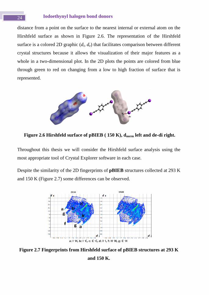
distance from a point on the surface to the nearest internal or external atom on the
Hirshfeld surface as shown in Figure 2.6. The representation of the Hirshfeld
surface is a colored 2D graphic (di, de) that facilitates comparison between different
crystal structures because it allows the visualization of their major features as a
whole in a two-dimensional plot. In the 2D plots the points are colored from blue
through green to red on changing from a low to high fraction of surface that is
represented.
Throughout this thesis we will consider the Hirshfeld surface analysis using the
most appropriate tool of Crystal Explorer software in each case.
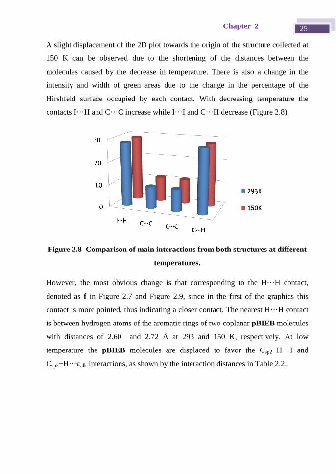
Despite the similarity of the 2D fingerprints of pBIEB structures collected at 293 K
and 150 K (Figure 2.7) some differences can be observed.
Figure 2.7 Fingerprints from Hirshfeld surface of pBIEB structures at 293 K
and 150 K.
Figure 2.6 Hirshfeld surface of pBIEB ( 150 K), dnorm left and de-di right.
Chapter 2 25
A slight displacement of the 2D plot towards the origin of the structure collected at
150 K can be observed due to the shortening of the distances between the
molecules caused by the decrease in temperature. There is also a change in the
intensity and width of green areas due to the change in the percentage of the
Hirshfeld surface occupied by each contact. With decreasing temperature the
contacts I···H and C···C increase while I···I and C···H decrease (Figure 2.8).
Figure 2.8 Comparison of main interactions from both structures at different
temperatures.
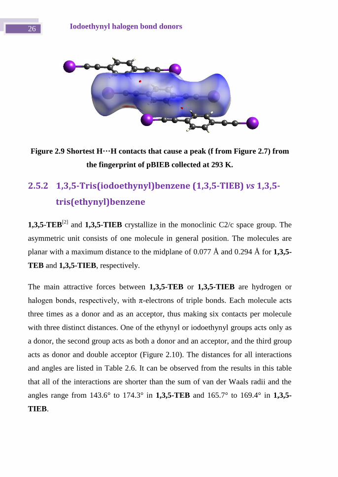
However, the most obvious change is that corresponding to the H···H contact,
denoted as f in Figure 2.7 and Figure 2.9, since in the first of the graphics this
contact is more pointed, thus indicating a closer contact. The nearest H···H contact
is between hydrogen atoms of the aromatic rings of two coplanar pBIEB molecules
with distances of 2.60 and 2.72 Å at 293 and 150 K, respectively. At low
temperature the pBIEB molecules are displaced to favor the Csp2−H···I and
Csp2−H···πalk interactions, as shown by the interaction distances in Table 2.2..
Iodoethynyl halogen bond donors 26
Figure 2.9 Shortest H···H contacts that cause a peak (f from Figure 2.7) from
the fingerprint of pBIEB collected at 293 K.
2.5.2 1,3,5-Tris(iodoethynyl)benzene (1,3,5-TIEB) vs 1,3,5-
tris(ethynyl)benzene
1,3,5-TEB[2]
and 1,3,5-TIEB crystallize in the monoclinic C2/c space group. The
asymmetric unit consists of one molecule in general position. The molecules are
planar with a maximum distance to the midplane of 0.077 Å and 0.294 Å for 1,3,5-
TEB and 1,3,5-TIEB, respectively.
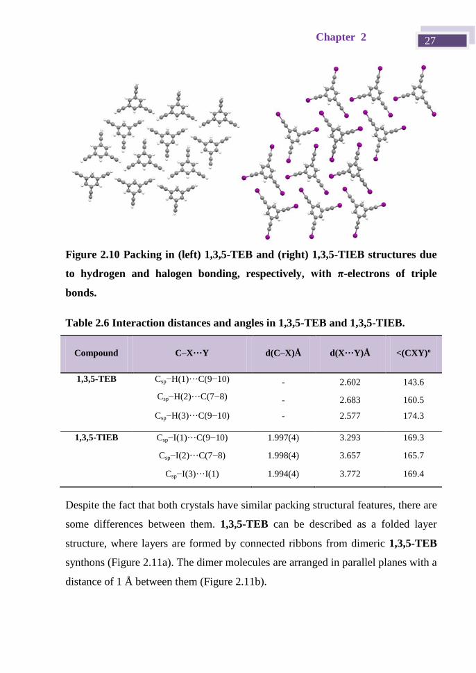
The main attractive forces between 1,3,5-TEB or 1,3,5-TIEB are hydrogen or
halogen bonds, respectively, with π-electrons of triple bonds. Each molecule acts
three times as a donor and as an acceptor, thus making six contacts per molecule
with three distinct distances. One of the ethynyl or iodoethynyl groups acts only as
a donor, the second group acts as both a donor and an acceptor, and the third group
acts as donor and double acceptor (Figure 2.10). The distances for all interactions
and angles are listed in Table 2.6. It can be observed from the results in this table
that all of the interactions are shorter than the sum of van der Waals radii and the
angles range from 143.6° to 174.3° in 1,3,5-TEB and 165.7° to 169.4° in 1,3,5-
TIEB.
Chapter 2 27
Figure 2.10 Packing in (left) 1,3,5-TEB and (right) 1,3,5-TIEB structures due
to hydrogen and halogen bonding, respectively, with π-electrons of triple
bonds.
Table 2.6 Interaction distances and angles in 1,3,5-TEB and 1,3,5-TIEB.
Compound C–X···Y d(C–X)Å d(X···Y)Å <(CXY)º
1,3,5-TEB Csp−H(1)···C(9−10) - 2.602 143.6
Csp−H(2)···C(7−8) - 2.683 160.5
Csp−H(3)···C(9−10) - 2.577 174.3
1,3,5-TIEB Csp−I(1)···C(9−10) 1.997(4) 3.293 169.3
Csp−I(2)···C(7−8) 1.998(4) 3.657 165.7
Csp−I(3)···I(1) 1.994(4) 3.772 169.4
Despite the fact that both crystals have similar packing structural features, there are
some differences between them. 1,3,5-TEB can be described as a folded layer
structure, where layers are formed by connected ribbons from dimeric 1,3,5-TEB
synthons (Figure 2.11a). The dimer molecules are arranged in parallel planes with a
distance of 1 Å between them (Figure 2.11b).
Iodoethynyl halogen bond donors 28
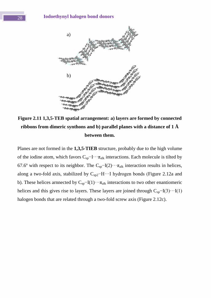
Figure 2.11 1,3,5-TEB spatial arrangement: a) layers are formed by connected
ribbons from dimeric synthons and b) parallel planes with a distance of 1 Å
between them.
Planes are not formed in the 1,3,5-TIEB structure, probably due to the high volume
of the iodine atom, which favors Csp−I···πalk interactions. Each molecule is tilted by
67.6º with respect to its neighbor. The Csp−I(2)···πalk interaction results in helices,
along a two-fold axis, stabilized by Csp2−H···I hydrogen bonds (Figure 2.12a and
b). These helices arnnected by Csp−I(1)···πalk interactions to two other enantiomeric
helices and this gives rise to layers. These layers are joined through Csp−I(3)···I(1)
halogen bonds that are related through a two-fold screw axis (Figure 2.12c).
a)
b)
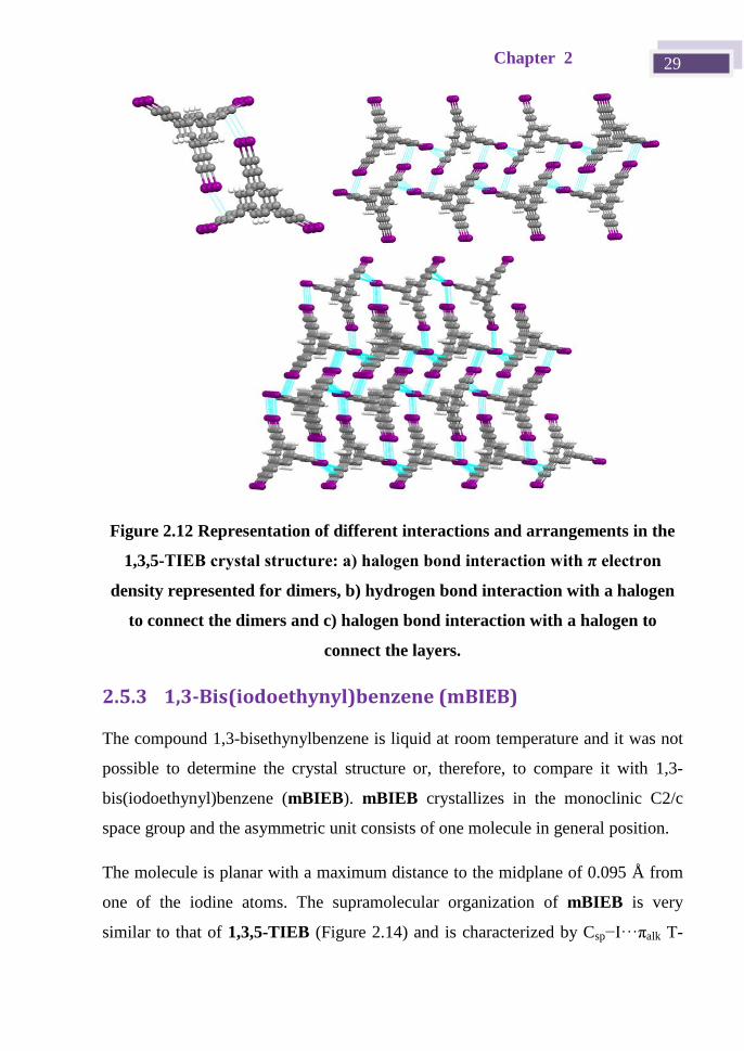
Chapter 2 29
Figure 2.12 Representation of different interactions and arrangements in the
1,3,5-TIEB crystal structure: a) halogen bond interaction with π electron
density represented for dimers, b) hydrogen bond interaction with a halogen
to connect the dimers and c) halogen bond interaction with a halogen to
connect the layers.
2.5.3 1,3-Bis(iodoethynyl)benzene (mBIEB)
The compound 1,3-bisethynylbenzene is liquid at room temperature and it was not
possible to determine the crystal structure or, therefore, to compare it with 1,3-
bis(iodoethynyl)benzene (mBIEB). mBIEB crystallizes in the monoclinic C2/c
space group and the asymmetric unit consists of one molecule in general position.
The molecule is planar with a maximum distance to the midplane of 0.095 Å from
one of the iodine atoms. The supramolecular organization of mBIEB is very
similar to that of 1,3,5-TIEB (Figure 2.14) and is characterized by Csp−I···πalk T-
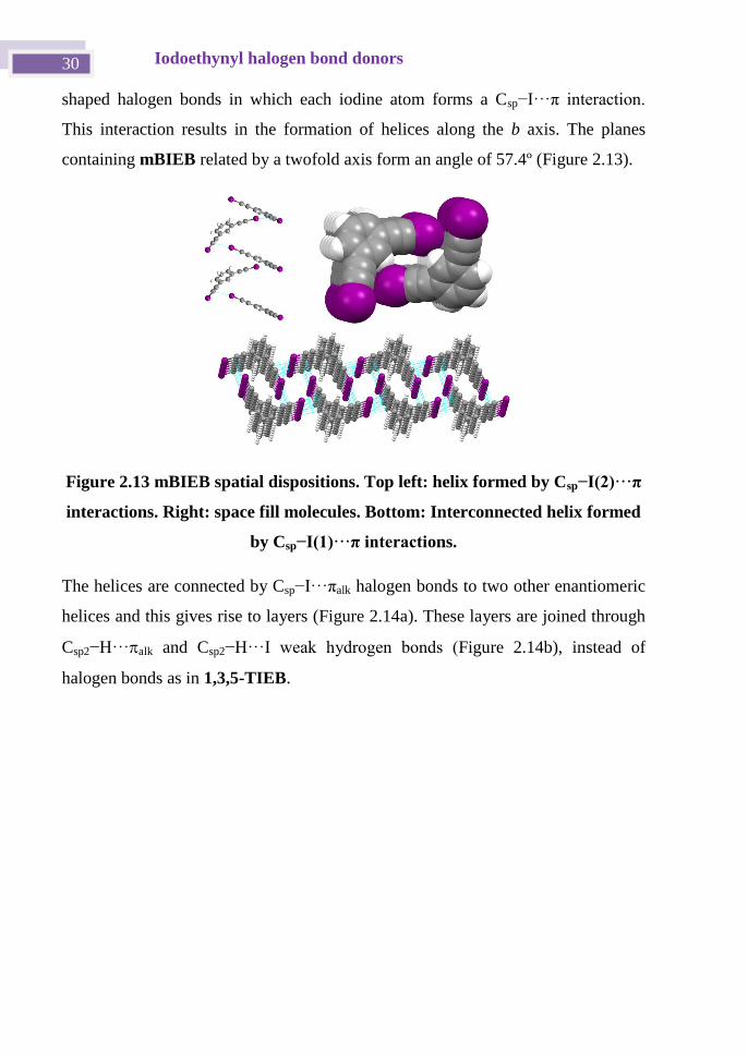
Iodoethynyl halogen bond donors 30
shaped halogen bonds in which each iodine atom forms a Csp−I···π interaction.
This interaction results in the formation of helices along the b axis. The planes
containing mBIEB related by a twofold axis form an angle of 57.4º (Figure 2.13).
Figure 2.13 mBIEB spatial dispositions. Top left: helix formed by Csp−I(2)···π
interactions. Right: space fill molecules. Bottom: Interconnected helix formed
by Csp−I(1)···π interactions.
The helices are connected by Csp−I···πalk halogen bonds to two other enantiomeric
helices and this gives rise to layers (Figure 2.14a). These layers are joined through
Csp2−H···alk and Csp2−H···I weak hydrogen bonds (Figure 2.14b), instead of
halogen bonds as in 1,3,5-TIEB.
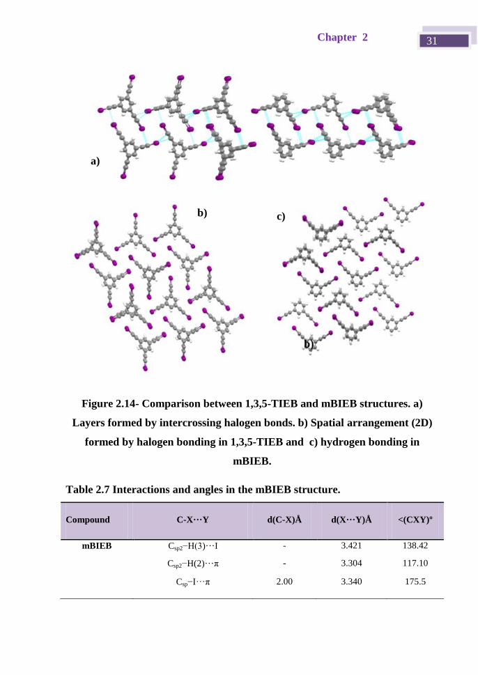
Chapter 2 31
Figure 2.14- Comparison between 1,3,5-TIEB and mBIEB structures. a)
Layers formed by intercrossing halogen bonds. b) Spatial arrangement (2D)
formed by halogen bonding in 1,3,5-TIEB and c) hydrogen bonding in
mBIEB.
Table 2.7 Interactions and angles in the mBIEB structure.
Compound C-X···Y d(C-X)Å d(X···Y)Å <(CXY)º
mBIEB Csp2−H(3)···I - 3.421 138.42
Csp2−H(2)···π - 3.304 117.10
Csp−I···π 2.00 3.340 175.5
b)
a)
b) c)
Iodoethynyl halogen bond donors 32
In the following sections the pairs dipropargyl terephthalate (pBPT)/bis(3-
iodoprop-2-yn-1-yl) terephthalate (pBIPT) and tri(prop-2-yn-1-yl) benzene-1,3,5-
tricarboxylate (1,3,5-TPCB)/tris(3-iodoprop-2-yn-1-yl) benzene-1,3,5-
tricarboxylate (1,3,5-TIPCB) will be compared. These compounds have different
properties such as conformational flexibility in the groups to which ethylnyl or
iodoethynyl groups are linked.
2.5.4 Bis(3-iodoprop-2-yn-1-yl) terephthalate (pBIPT) vs
bispropargyl terephthalate (pBPT)
Bispropargylterephthalate (pBPT) – like pBIPT – crystallizes in the triclinic P-1
space group and the asymmetric units consists of two half molecules with an
inversion center. Furthermore, in both structures the carbonyl groups have a trans
conformation. Regarding the conformation, in the pBIPT molecule the
iodopropynoxycarbonyl group is tilted in relation to aromatic ring by ca. 6 º and in
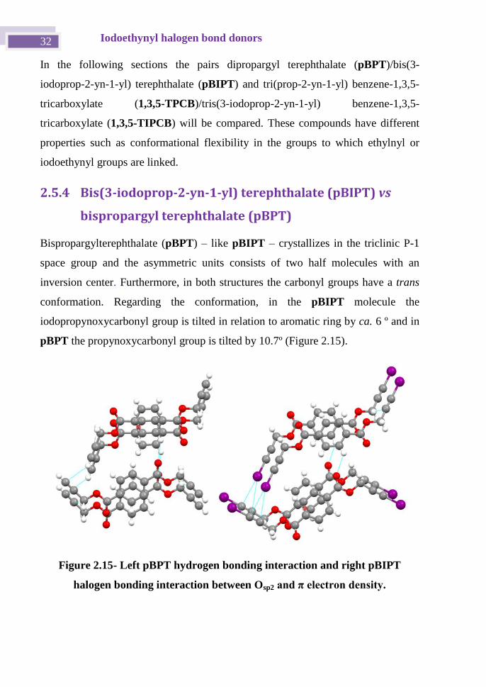
pBPT the propynoxycarbonyl group is tilted by 10.7º (Figure 2.15).
Figure 2.15- Left pBPT hydrogen bonding interaction and right pBIPT
halogen bonding interaction between Osp2 and π electron density.
Chapter 2 33
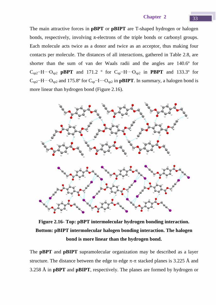
The main attractive forces in pBPT or pBIPT are T-shaped hydrogen or halogen
bonds, respectively, involving π-electrons of the triple bonds or carbonyl groups.
Each molecule acts twice as a donor and twice as an acceptor, thus making four
contacts per molecule. The distances of all interactions, gathered in Table 2.8, are
shorter than the sum of van der Waals radii and the angles are 140.6º for
Csp2−H···Osp2 pBPT and 171.2 º for Csp−H···Osp2 in PBPT and 133.3º for
Csp2−H···Osp2 and 175.8º for Csp−I···Osp2 in pBIPT. In summary, a halogen bond is
more linear than hydrogen bond (Figure 2.16).
Figure 2.16- Top: pBPT intermolecular hydrogen bonding interaction.
Bottom: pBIPT intermolecular halogen bonding interaction. The halogen
bond is more linear than the hydrogen bond.
The pBPT and pBIPT supramolecular organization may be described as a layer
structure. The distance between the edge to edge - stacked planes is 3.225 Å and
3.258 Å in pBPT and pBIPT, respectively. The planes are formed by hydrogen or
Iodoethynyl halogen bond donors 34
halogen bonding between ethynyl or iodoethynyl and the carbonyl group Csp–
D···O (D = H, I), with chains joined by hydrogen or halogen bonding Csp–D···πalk
(D = H, I) (Figure 2.16).
Table 2.8 Interaction distances and angles in pBPT and pBIPT.
Compound C-D···Y d(C-D)Å d(D···Y)Å <(CXY)º
pBPT Csp−H···Osp2 0.930 2.180 171.2
Csp2−H···Osp2 0.930 2.450 140.6
pBIPT Csp−I···Osp2 2.014 2.828 175.8
Csp3−H···I 0.970 3.1776 126.2
Csp2−H···Osp2 0.930 2.475 133.3
Csp3−H···Csp 0.970 2.819 159.8
2.5.5 Tris(3-iodoprop-2-yn-1-yl) benzene-1,3,5-
tricarboxylate (1,3,5-TIPCB) vs tris(prop-2-yn-1-yl)
benzene-1,3,5-tricarboxylate (1,3,5-TPCB)
In the tris(prop-2-yn-1-yl) benzene-1,3,5-tricarboxylate (1,3,5-TPCB) and tris(3-
iodoprop-2-yn-1-yl) benzene-1,3,5-tricarboxylate (1,3,5-TIPCB) structures, the
supramolecular arrangements are very different, although in solid state the nature
and number of interactions and conformations are similar. The three ethynyl groups
act as hydrogen bond donors and the three iodoethynyl groups as halogen bond
donors. The halogen and hydrogen bond acceptors are the same in both
compounds. One of these is the π electron density of the triple bond and the other
two are the sp2
oxygen and sp3 oxygen of the carboxylate groups.
As far as the conformation is concerned, both structures have 1,3,5-trimesylate as a
core and this is practically plane with carboxylate angles in the range 6.2–17.7º in
1,3,5-TPCB and 1.1–7.3º in 1,3,5-TIPCB. However, the propargyl groups have
different orientations in the two structures. In the 1,3,5-TIPCB structure the three
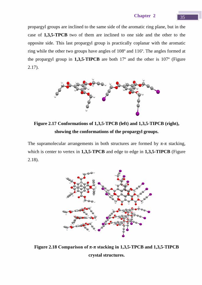
Chapter 2 35
propargyl groups are inclined to the same side of the aromatic ring plane, but in the
case of 1,3,5-TPCB two of them are inclined to one side and the other to the
opposite side. This last propargyl group is practically coplanar with the aromatic
ring while the other two groups have angles of 108º and 116º. The angles formed at
the propargyl group in 1,3,5-TIPCB are both 17º and the other is 107º (Figure
2.17).
Figure 2.17 Conformations of 1,3,5-TPCB (left) and 1,3,5-TIPCB (right),
showing the conformations of the propargyl groups.
The supramolecular arrangements in both structures are formed by π-π stacking,
which is center to vertex in 1,3,5-TPCB and edge to edge in 1,3,5-TIPCB (Figure
2.18).
Figure 2.18 Comparison of π-π stacking in 1,3,5-TPCB and 1,3,5-TIPCB
crystal structures.
Iodoethynyl halogen bond donors 36
The tris(prop-2-yn-1-yl) benzene-1,3,5-tricarboxylate (1,3,5-TPCB) crystallizes in
the monoclinic P21/c space group. The core packing mentioned above grows along
the c axis and molecules are not parallel, with an angle of 10.7º between them. The
shortest distance measured between molecules is 3.31 Å (see Figure 2.18). The
molecular packing is stabilized by Csp−H···πalk hydrogen bonds and the
supramolecular organization is completed by the union of each column with
another four hydrogen bonds. Two of these bonds are of the type Csp−H···Osp2 and
the other two are Csp−H···Osp3. (All the distance are gathered at Table 2.9)
Table 2.9- Interaction distances and angles in 1,3,5-TPCB and 1,3,5-TIPCB.
Compound C-X···Y d(C-X)Å d(X···Y)Å <(CXY)º
1,3,5-TPCB Csp-H···Osp3 - 2.70(2) 125(1)
Csp-H···πalk - 2.84(2) 144(2)
Csp-H···Osp2 - 2.42(2) 147(2)
1,3,5-TIPCB Csp-I···Osp3 2.02(2) 3.377(9) 162.2(6)
Csp-I···πalk 2.00(1) 3.218 176.84
Csp-I···Osp2 1.98(2) 2.890(1) 177.2(6)
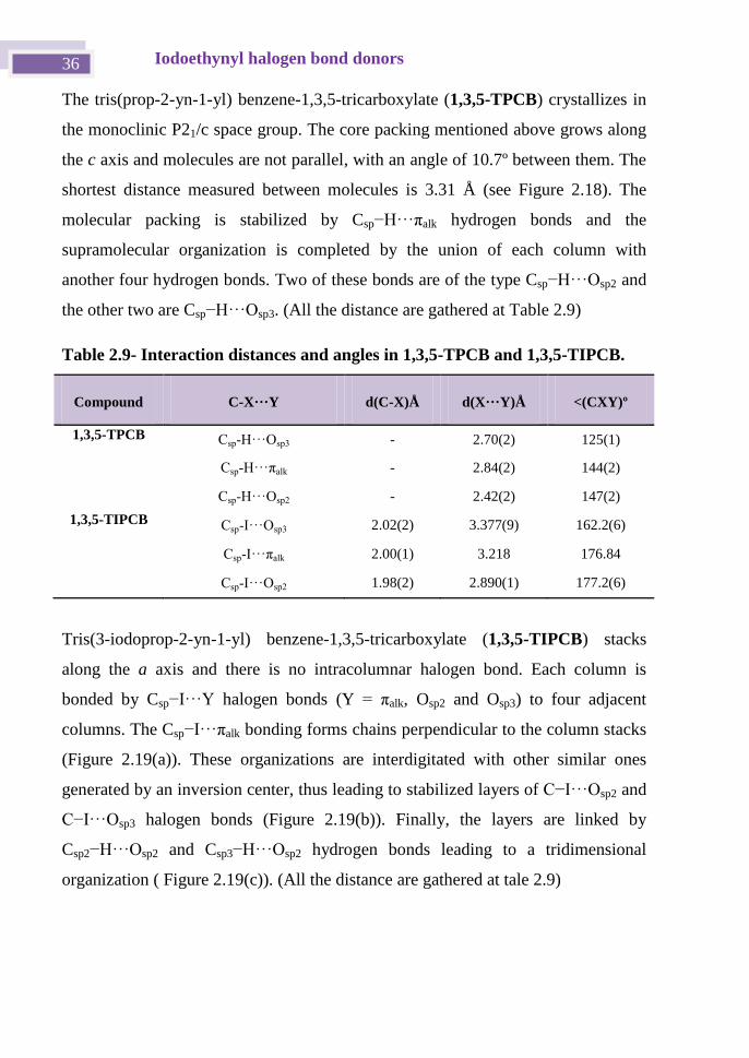
Tris(3-iodoprop-2-yn-1-yl) benzene-1,3,5-tricarboxylate (1,3,5-TIPCB) stacks
along the a axis and there is no intracolumnar halogen bond. Each column is
bonded by Csp−I···Y halogen bonds (Y = πalk, Osp2 and Osp3) to four adjacent
columns. The Csp−I···πalk bonding forms chains perpendicular to the column stacks
(Figure 2.19(a)). These organizations are interdigitated with other similar ones
generated by an inversion center, thus leading to stabilized layers of C−I···Osp2 and
C−I···Osp3 halogen bonds (Figure 2.19(b)). Finally, the layers are linked by
Csp2−H···Osp2 and Csp3−H···Osp2 hydrogen bonds leading to a tridimensional
organization ( Figure 2.19(c)). (All the distance are gathered at tale 2.9)
Chapter 2 37
Figure 2.19 Interdigitated connection for 1,3,5-TIPCB: a) Csp−I···πalk halogen
bonding interaction, b) stabilization of layers by Csp−I···Osp2 and Csp−I···Osp3
halogen bonds and c) tridimensional organization linked by Csp2−H···Osp2 and
Csp3−H···Osp2 hydrogen bonds.
a)
b)
c)
Iodoethynyl halogen bond donors 38
2.6 Conclusions
In this section it has been explained how alkynes and iodoalkynes, which are planar
and rigid molecules, result in isostructural supramolecular arrangements. The
differences between structures become more marked with the number of ethynyl
groups and their proximity.
However, flexible molecules do not give rise to isostructuralism and the structure is
not governed by the strongest interaction alone, e.g. halogen bond or hydrogen
bond (Csp−I···Y and Csp−H···Y). Other weak interactions, such as Csp2−H···Y, are
important for the final packing/crystal structure.
Chapter 2 39
2.7 Experimental Section
2.7.1 Synthesis and characterization of halogenated
derivatives and their precursors
1,3- and 1,4-bisethynylbenzene, 1,3,5-triethynylbenzene, 1,4-benzenedicarbonyl
dichloride, 1,3,5-benzenetricarbonyl trichloride, N-iodosuccinimide, 2-propyn-1-ol
and silver nitrate were used as received from commercial sources.
1H and
13C NMR spectra were recorded on a Bruker Avance 400 spectrometer
(400.13 MHz for 1H, 100.62 MHz for
13C) or a Bruker Avance 300 spectrometer
(300 MHz for 1H, 75 MHz for
13C). Infrared (IR) spectra were recorded on an
ATR-unit-upgraded (Golden Gate) Bruker FT-IR Vertex 70 spectrophotometer.
Mass spectra were recorded on a VG Auto-spec instrument, with the ESI
technique. C, H, and N analyses were carried out on a Perkin-Elmer 2400
microanlyzer.
Halogenation procedures for all of the halogen bonding donors synthesized were
carried out in the same way, with slight modification as reported previously.[28]
2.7.2 General method
N-Iodosuccinimide (NIS) and AgNO3 in a Schlenk tube were put under vacuum for
10 minutes. Acetylene in DMF or acetone under an argon atmosphere was slowly
added to the Schlenk tube at 0 ºC (ice/water bath). After 5 hours the mixture was
filtered and added to water. The product was extracted three times with diethyl
ether and cooled until a precipitate formed. The solid was filtered off and the ether
was evaporated from the filtrate to give the product. Yields: 80–88%.
Iodoethynyl halogen bond donors 40
2.7.3 Characterization of halogen derivatives
1,4-Bis(iodoethynyl)benzene (pBIEB): 1H NMR (300 MHz, CDCl3) δ ppm: .3 (s,
4H). 13
C NMR (75 MHz, CDCl3) δ ppm: .14 (CAlk−I), .1 (CAlk−Ar), 3. 4
(CAr−Alk), 123.88, 132.27.
1,3-Bis(iodoethynyl)benzene (mBIEB): 1H NMR (300 MHz, CDCl3) δ ppm: .4
(t, J = 1.4 Hz, 1H), 7.41–7.33 (m, 2H), 7.29–7.20 (m, 1H). 13
C NMR (75 MHz,
CDCl3) δ (ppm): . (CAlk−I), 3.23 (CAlk−Ar), 123. 8 (CAr−Alk), 128.40, 132. ,
136.20, 212.26.
1,3,5-Tris(iodoethynyl)benzene (1,3,5-TIB): 1H NMR (300 MHz, CDCl3) δ ppm:
7.44 (d, J = 0.8 Hz, 3H, 1, 3, 5). 13
C NMR (75 MHz, CDCl3) δ ppm: .14 (CAlk−I),
92.29 (CAlk−Ar), 124.11 (CAr−Alk), 13 . .
Bis(3-iodoprop-2-yn-1-yl) terephthalate (pBIPT): 1H NMR (300 MHz, CDCl3) δ
ppm: 8.14 (s, 4H), 5.09 (s, 4H).
Tris(3-iodoprop-2-yn-1-yl) benzene-1,3,5-tricarboxylate (1,3,5-TIPCB): 1H NMR
(300 MHz, CDCl3) δ ppm: 8.92 (s, 3H), 5.13 (s, 6H).
2.7.4 X-ray monocrystal diffraction
The crystals are air stable and were mounted on the tip of a glass fiber with epoxy
cement. X-ray diffraction experiments were carried out on an Oxford-diffraction
Xcalibur S diffractometer. Data were collected at 293 K and 150 K with Mo- or
Cu-Kα radiation. The software package CrysAlys was used to process data.
Final cell parameters were obtained by global refinement of reflections obtained
from integration of all the frames data. The structures were solved by direct
methods and refined by the full-matrix method based on F2 using SHELXTL
program. The non-hydrogen atoms of structures were refined anisotropically, the
hydrogen atoms were observed in difference electro density maps and refined
Chapter 2 41
isotropically. The crystal parameters and basic information relating data collection
and structure refinement for the compounds are summarized in Table 2.10.
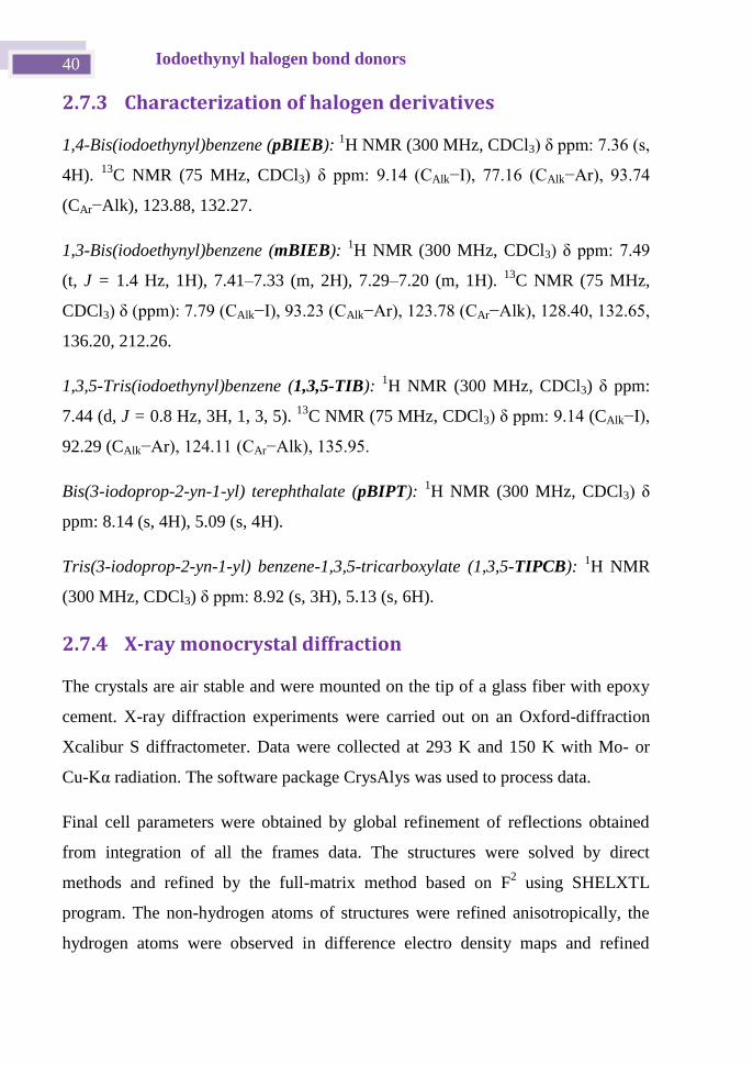
Table 2.10 Crystal information of all bisethynyl and bisiodoethynyl crystal
structures.
Compound mBIEB 1,3,5-TIEBb 1,3,5-TPCB 1,3,5-TIPCB pBPT pBIPT
Emp. formula
C10H4I2 C12H3I3 C18H12O6 C18H9I3O6 C14H10O4 C14H8I2O4
Formula weight
377.93 527.84 324.28 701.95 242.22 494.00
Crystal system
Monoclinic Triclinic Monoclinic Triclinic Triclinic Triclinic
a, Å 26.391(2) 8.6958(3) 11.1986(2) 4.2720(4) 3.9232(15) 4.1912(2)
b, Å 4.2415(3) 17.5984(7) 20.6035(3) 15.6898(10) 11.954(3) 13.6263(6)
c , Å 19.9116(15) 18.9764(8) 6.89860(10) 16.4678(10) 13.796(2) 13.6994(5)
α, deg 90 74.068(4) 90 113.383(6) 113.394(19) 104.683(3)
β, deg 108.977(9) 89.992(3) 96.081(2) 94.355(6) 95.08(2) 92.070(4)
γ , deg 90 82.891(3) 90 95.533(7) 90.24(2) 95.855(4)
Volume, Å3 2107.7(3) 2769.25(19) 1582.76(4) 1000.50(13) 591.0(3) 751.32(6)
T, K 293(2) 293(2) 99.98(10) 100.01(10) 100(2) 100.00(10)
Space group C2/c P -1 P21/c P -1 P -1 P-1
Z 8 8 4 2 2 2
μ(X Kα), mm-1 5.913 6.740 0.872 (Cu) 37.091(Cu) 0.840 (Cu) 32.977 (Cu)
θ range, deg 3.11 to 26.22 3.15 to 24.71 3.97 to 74.25 2.95 to 67.00 3.51 to 74.12 3.34 to 73.91
Refl. collected
5038 39854 12955 3763 3370 4988
Uniq reflect/ Rint
1777 / 0.0639 9429 / 0.0331 3172 / 0.0289 3763/0.0000 1814 / 0.0762 2913 / 0.0371
R1/wR2 [I>2σ]
0.0662 / 0.0978
0.0491 / 0.1417 0.0321/0.0831 0.1002/ 0.2770
0.0887 / 0.2590
0.0389 / 0.0970
R1/wR2 (all data)
0.1179 / 0.1168
0.0908/ 0.1740 0.0365/ 0.0861 0.1099/ 0.2894
0.1433 / 0.2883
0.0430 / 0.1010
Residual ρ/
e Å-3 0.651 /-0.655 1980 / -1.480 0.272 / -0.229 3.127/-3.432 0.432/ -0.414
2.809/ -1.233
2.7.5 Hirshfeld Surfaces
Hirshfeld surfaces and the associated fingerprint plots were calculated using
CrystalExplorer,[29]
which accepts a structure input file in the CIF format. Bond
lengths to hydrogen atoms were set to typical neutron values (C–H = 1.083 Å, N–H
= 1.009 Å, O–H = 0.983 Å). The distance from the Hirshfeld surface to the nearest
atoms outside and inside the surface are characterized by the quantities de and di,
Iodoethynyl halogen bond donors 42
respectively, and the normalized contact distance based on these, dnorm = (di –
rivdW
)/ rivdW
+( de – revdW
)/ revdW
), with rivdW
and revdW
being the van der Waals radii
of the atoms. The 2D histograms, fingerprints, plot distance external to the surface
(de) versus distance internal to the surface (di): is the distance from the surface to
the nearest atom in the molecule itself.
Chapter 2 43
2.8 Final Remarks
In this first chapter the preparation of halogen bond donors derived from
iodoethynyl has been introduced. All halogen derivatives described were
synthesized from their corresponding alkynes. Differences between each halogen
molecule are the number of halogen bond donors and the conformational flexibility
of groups. Crystal structures of the precursors and halogen derivatives were
determined and compared. In spite of the differences in atom size (hydrogen and
iodine), the interaction energy leads to similar supramolecular organizations.
In the following chapters the design of new with the halogen bond donors will be
discussed.
Iodoethynyl halogen bond donors 44
2.9 Bibliography
[1] a) L. Turunen, N. K. Beyeh, F. Pan, A. Valkonen and K. Rissanen, Chem. Commun. 2014, 50,
15920-15923; b) O. Dumele, D. Wu, N. Trapp, N. Goroff and F. Diederich, Org. Lett. 2014, 16,
4 22−4 2 c) J. Lieffrig, O. Jeannin and M. ourmigué, J. Am. Chem. Soc. 2013, 135, 6200; d) C.
Lemouchi, C. S. Vogelsberg, L. Zorina, S. Simonov, P. Batail, S. Brown and M. A. Garcia-Garibay,
J. Am. Chem. Soc. 2011, 133, 6371-6379.
[2] H.-C. Weiss, D. Blaser, R. Boese, B. M. Doughan and M. M. Haley, Chem. Commun. 1997,
1703-1704.
[3] F. Guthrie, J. Chem. Soc. 1863, 16, 239.
[4] B. Casper, H.-G. Mack, H. S. P. Mueller, H. Willner and H. Oberhammer, J. Phys. Chem. 1994,
98, 8339-8342.
[5] H. A. Bent, Chem. Rev. 1968, 68, 587.
[6] a) T. Brinck, J. S. Murray and P. Politzer, Int. J. Quantum Chem. 1992, 44, 57; b) T. Brinck, J.
S. Murray and P. Politzer, Int. J. Quantum Chem. 1993, 48, 73-88; c) J. S. Murray, K. Paulsen and
P. Politzer, Proc.—Indian Acad. Sci., Chem. Sci. 1994, 106, 267.
[7] G. Valerio, G. Raos, S. V. Meille, P. Metrangolo and G. Resnati, J. Phys. Chem. A 2000, 104,
1617-1620.
[8] a) V. Nefedov, Russ. J. Org. Chem. 2007, 43, 1163-1166; b) A. Takemura, L. J. McAllister, S.
Hart, N. E. Pridmore, P. B. Karadakov, A. C. Whitwood and D. W. Bruce, Chem. Eur. J. 2014, 20,
6721-6732; c) A. Vargas Jentzsch and S. Matile, J. Am. Chem. Soc. 2013, 135, 5302; d) F. Zapata,
A. Caballero, N. G. White, T. D. W. Claridge, P. J. Costa, V. Felix and P. D. Beer, J. Am. Chem.
Soc. 2012, 134, 11533-11 41 e) A. Mateo‐Alonso, N. Kulisic, G. Valenti, M. Marcaccio, F.
Paolucci and M. Prato, Chem. Asian J. 2010, 5, 482-485; f) P. Cardillo, E. Corradi, A. Lunghi, S.
Meille, M. Messina, P. Metrangolo and G. Resnati, Tetrahedron 2000, 56, 5535-5550; g) X. Pang
and W. J. Jin in Halogen Bonding in the Design of Organic Phosphors, Vol. Springer, 2014, pp.
115-146; h) P. Metrangolo, H. Neukirch, T. Pilati and G. Resnati, Acc. Chem. Res. 2005, 38, 386-
395; i) A. Forni, P. Metrangolo, T. Pilati and G. Resnati, Cryst. Growth Des. 2004, 4, 291.
[9] H. M. Yamamoto, Y. Kosaka, R. Maeda, J.-i. Yamaura, A. Nakao, T. Nakamura and R. Kato,
Acs Nano 2008, 2, 143-155.
[10] C. Lemouchi, C. S. Vogelsberg, L. Zorina, S. Simonov, P. Batail, S. Brown and M. A. Garcia-
Garibay, J. Am. Chem. Soc. 2011, 133, 6371-6379.
[11] C. Perkins, S. Libri, H. Adams and L. Brammer, CrystEngComm 2012, 14, 3033-3038.
[12] a) N. S. Goroff, S. M. Curtis, J. A. Webb, F. W. Fowler and J. W. Lauher, Organic Letters
2005, 7, 1891-1893; b) H. Jin, A. M. Plonka, J. B. Parise and N. S. Goroff, CrystEngComm 2013,
15, 3106.
[13] C. B. Aakeröy, M. Baldrighi, J. Desper, P. Metrangolo and G. Resnati, Chemistry – A
European Journal 2013, 19, 16240-16247.
[14] M. Baldrighi, G. Cavallo, M. R. Chierotti, R. Gobetto, P. Metrangolo, T. Pilati, G. Resnati and
G. Terraneo, Mol. Pharmaceutics 2013, 10, 1760-1772.
[15] S. Cicchi, P. Fabbrizzi, G. Ghini, A. Brandi, P. Foggi, A. Marcelli, R. Righini and C. Botta,
Chem. Eur. J. 2009, 15, 754-764.
[16] G. Chen, J. Kumar, A. Gregory and M. H. Stenzel, Chem. Commun. 2009, 6291-6293.
[17] K. Bouchmella, B. Boury, S. G. Dutremez and A. van der Lee, Chem. Eur. J. 2007, 13, 6130-
6138.
[18] W. Z. Guo, E. Galoppini, R. Gilardi, G. I. Rydja and Y. H. Chen, Cryst. Growth Des. 2001, 1,
231-237.
[19] D. Cincic, T. Friscic and W. Jones, New J. Chem. 2008, 32, 1776-1781.
[20] D. Cincic, T. Friscic and W. Jones, J. Am. Chem. Soc. 2008, 130, 7524-7525.
[21] a) J. J. Novoa and F. Mota, Chem. Phys. Lett. 2000, 318, 345-354; b) O. V. Shishkin, Chem.
Phys. Lett. 2008, 458, 96-100.
[22] A. Bondi, J. Phys. Chem. 1964, 68, 441-451.
Chapter 2 45
[23] A. L. Barres, A. El-Ghayoury, L. V. Zorina, E. Canadell, P. Auban-Senzier and P. Batail,
Chem. Commun. 2008, 2194-2196.
[24] V. G. Saraswatula and B. K. Saha, New J. Chem. 2014, 38, 897-901.
[25] K. Wang, D. Duan, M. Zhou, S. Li, T. Cui, B. Liu, J. Liu, B. Zou and G. Zou, J Phys. Chem. B
2011, 115, 4639-4644.
[26] a) R. H. Baughman, J. Org. Chem. 1964, 29, 964-&; b) A. S. Batsanov and J. A. K. Howard,
Acta Crystallogr. 2000, C56, 252-253.
[27] G. Drefahl and E. Keil, J. Prakt. Chem. 1958, 6, 80-80.
[28] L. Gonzalez, N. Gimeno, R. Maria Tejedor, V. Polo, M. Blanca Ros, S. Uriel and J. Luis
Serrano, Chem. Mat. 2013, 25, 4503-4510.
[29] M. A. Spackman and D. Jayatilaka, CrystEngComm 2009, 11, 19-32.

Chapter 3 Iodo Tröger’s Base derivatives:
Towards halogen bonded porous organic
crystalline materials

Chapter 3 49
3.1 Introduction
The preparation of porous materials has become an important challenge in
Materials Science due the applications of such systems in fields as diverse as
petrochemistry,[1]
water purification,[2]
and fuel cells,[3]
amongst others. The unique
geometry and complementarity of Tröger's base makes it especially useful for this
purpose. Taking into account the general objective of the PhD work described here,
this chapter is devoted to the design, synthesis and crystal structure characterization
of some diiodo Tröger’s base derivatives with the aim of obtaining stable porous
crystalline materials.
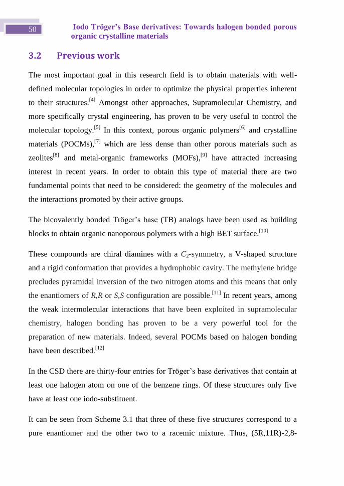
Iodo Tröger’s Base derivatives: Towards halogen bonded porous
organic crystalline materials 50
3.2 Previous work
The most important goal in this research field is to obtain materials with well-
defined molecular topologies in order to optimize the physical properties inherent
to their structures.[4]
Amongst other approaches, Supramolecular Chemistry, and
more specifically crystal engineering, has proven to be very useful to control the
molecular topology.[5]
In this context, porous organic polymers[6]
and crystalline
materials (POCMs),[7]
which are less dense than other porous materials such as
zeolites[8]
and metal-organic frameworks (MOFs),[9]
have attracted increasing
interest in recent years. In order to obtain this type of material there are two
fundamental points that need to be considered: the geometry of the molecules and
the interactions promoted by their active groups.
The bicovalently bonded Tröger’s base (TB) analogs have been used as building
blocks to obtain organic nanoporous polymers with a high BET surface.[10]
These compounds are chiral diamines with a C2-symmetry, a V-shaped structure
and a rigid conformation that provides a hydrophobic cavity. The methylene bridge
precludes pyramidal inversion of the two nitrogen atoms and this means that only
the enantiomers of R,R or S,S configuration are possible.[11]
In recent years, among
the weak intermolecular interactions that have been exploited in supramolecular
chemistry, halogen bonding has proven to be a very powerful tool for the
preparation of new materials. Indeed, several POCMs based on halogen bonding
have been described.[12]
In the CSD there are thirty-four entries for Tröger’s base derivatives that contain at
least one halogen atom on one of the benzene rings. Of these structures only five
have at least one iodo-substituent.
It can be seen from Scheme 3.1 that three of these five structures correspond to a
pure enantiomer and the other two to a racemic mixture. Thus, (5R,11R)-2,8-
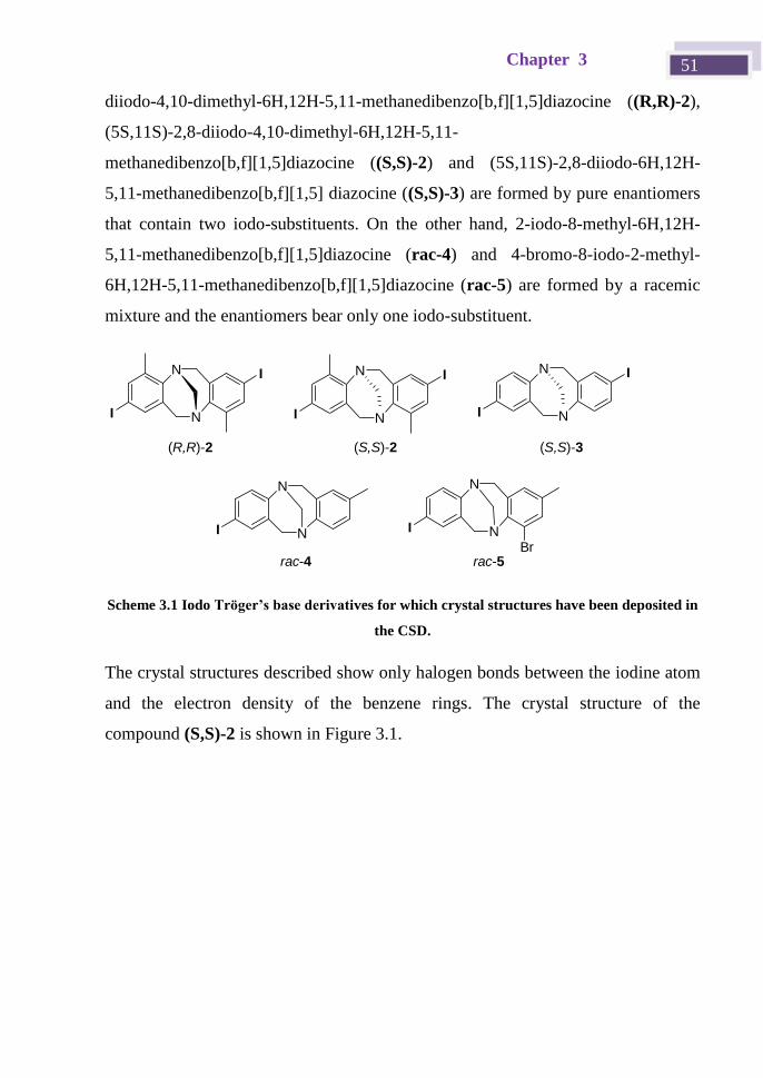
Chapter 3 51
diiodo-4,10-dimethyl-6H,12H-5,11-methanedibenzo[b,f][1,5]diazocine ((R,R)-2),
(5S,11S)-2,8-diiodo-4,10-dimethyl-6H,12H-5,11-
methanedibenzo[b,f][1,5]diazocine ((S,S)-2) and (5S,11S)-2,8-diiodo-6H,12H-
5,11-methanedibenzo[b,f][1,5] diazocine ((S,S)-3) are formed by pure enantiomers
that contain two iodo-substituents. On the other hand, 2-iodo-8-methyl-6H,12H-
5,11-methanedibenzo[b,f][1,5]diazocine (rac-4) and 4-bromo-8-iodo-2-methyl-
6H,12H-5,11-methanedibenzo[b,f][1,5]diazocine (rac-5) are formed by a racemic
mixture and the enantiomers bear only one iodo-substituent.
Scheme 3.1 Iodo Tröger’s base derivatives for which crystal structures have been deposited in
the CSD.
The crystal structures described show only halogen bonds between the iodine atom
and the electron density of the benzene rings. The crystal structure of the
compound (S,S)-2 is shown in Figure 3.1.
N
N
I N
N
I
Br
N
N
I
I
N
N
I
I
N
N
I
I
(S,S)-2 (S,S)-3(R,R)-2
rac-4 rac-5
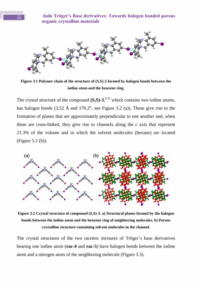
Iodo Tröger’s Base derivatives: Towards halogen bonded porous
organic crystalline materials 52
Figure 3.1 Polymer chain of the structure of (S,S)-2 formed by halogen bonds between the
iodine atom and the benzene ring.
The crystal structure of the compound (S,S)-3,[13]
which contains two iodine atoms,
has halogen bonds (3.52 Å and 170.2°, see Figure 3.2 (a)). These give rise to the
formation of planes that are approximately perpendicular to one another and, when
these are cross-linked, they give rise to channels along the c axis that represent
21.3% of the volume and in which the solvent molecules (hexane) are located
(Figure 3.2 (b)).
Figure 3.2 Crystal structure of compound (S,S)-3. a) Structural planes formed by the halogen
bonds between the iodine atom and the benzene ring of neighboring molecules. b) Porous
crystalline structure containing solvent molecules in the channel.
The crystal structures of the two racemic mixtures of Tröger’s base derivatives
bearing one iodine atom (rac-4 and rac-5) have halogen bonds between the iodine
atom and a nitrogen atom of the neighboring molecule (Figure 3.3).
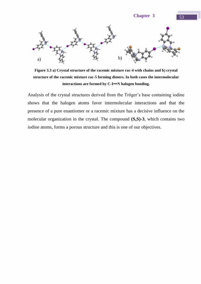
Chapter 3 53
Figure 3.3 a) Crystal structure of the racemic mixture rac-4 with chains and b) crystal
structure of the racemic mixture rac-5 forming dimers. In both cases the intermolecular
interactions are formed by C-I•••N halogen bonding.
Analysis of the crystal structures derived from the Tröger’s base containing iodine
shows that the halogen atoms favor intermolecular interactions and that the
presence of a pure enantiomer or a racemic mixture has a decisive influence on the
molecular organization in the crystal. The compound (S,S)-3, which contains two
iodine atoms, forms a porous structure and this is one of our objectives.
a) b)
Iodo Tröger’s Base derivatives: Towards halogen bonded porous
organic crystalline materials 54
3.3 Objectives and planning
3.3.1 Objectives
The main objective of this work was to obtain porous crystalline materials using
diiodo Tröger’s base derivatives as molecular units.
In the design of these compounds our idea was to use the halogen bonding
interactions in order to favor the formation of porous structures.
Taking into account the chirality of Tröger’s bases and the complemenatry nature
of the structural packing of the enantiomers, a comparative study between the
crystalline structures of the racemic mixture and a single pure enantiomer was
carried out.
3.3.2 Planning
In order to achieve these objectives and taking into account the literature review,
we decided to combine Tröger’s base analogs and halogen bonding to obtain
porous crystalline materials by taking advantage of the geometry and
complementary nature of iodo Tröger’s base derivatives. We prepared and
characterized the crystalline structures of three iodo-containing Tröger’s base
derivatives functionalized in positions 2 and 8.
A racemic mixture of a derivative containing two iodo-substituents (2,8-diiodo-
6H,12H-5,11-methanodibenzo[b,f][1,5]diazocine (rac-1), the pure enantiomer (2,8-
diiodo-6H,12H-5,11-methano-dibenzo[b,f][1,5]diazocine (5S,11S-1) and a racemic
mixture containing two ethynyl groups (2,8-bis(iodoethynyl)-6H,12H-5,11-
methanodibenzo[b,f][1,5]diazocine, rac-2). The structures are shown in Scheme
3.2.
The racemic (rac-1) and the enantiopure (5S,11S)-1 compounds were selected to
compare their ability to form porous crystalline structures. The classical allach’s
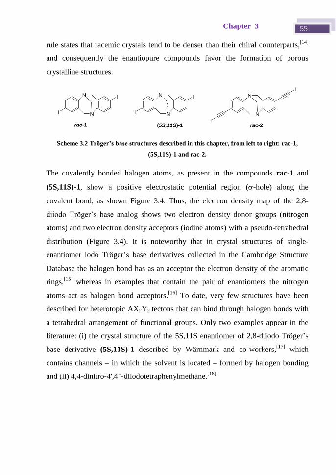
Chapter 3 55
rule states that racemic crystals tend to be denser than their chiral counterparts,[14]
and consequently the enantiopure compounds favor the formation of porous
crystalline structures.
N
N
I
I
N
N
I
I
rac-1 (5S,11S)-1
N
N
rac-2
I
I
Scheme 3.2 Tröger’s base structures described in this chapter, from left to right: rac-1,
(5S,11S)-1 and rac-2.
The covalently bonded halogen atoms, as present in the compounds rac-1 and
(5S,11S)-1, show a positive electrostatic potential region (-hole) along the
covalent bond, as shown Figure 3.4. Thus, the electron density map of the 2,8-
diiodo Tröger’s base analog shows two electron density donor groups (nitrogen
atoms) and two electron density acceptors (iodine atoms) with a pseudo-tetrahedral
distribution (Figure 3.4). It is noteworthy that in crystal structures of single-
enantiomer iodo Tröger’s base derivatives collected in the Cambridge Structure
Database the halogen bond has as an acceptor the electron density of the aromatic
rings,[15]
whereas in examples that contain the pair of enantiomers the nitrogen
atoms act as halogen bond acceptors.[16]
To date, very few structures have been
described for heterotopic AX2Y2 tectons that can bind through halogen bonds with
a tetrahedral arrangement of functional groups. Only two examples appear in the
literature: (i) the crystal structure of the 5S,11S enantiomer of 2,8-diiodo Tröger’s
base derivative (5S,11S)-1 described by Wärnmark and co-workers,[17]
which
contains channels – in which the solvent is located – formed by halogen bonding
and (ii) 4,4-dinitro-4',4"-diiodotetraphenylmethane.[18]
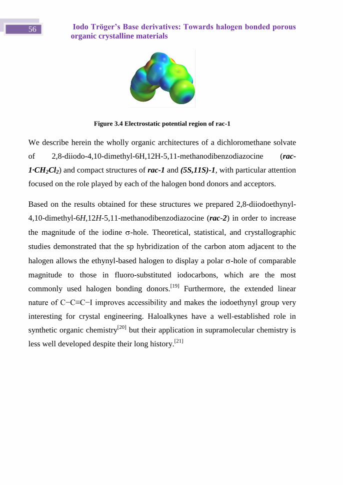
Iodo Tröger’s Base derivatives: Towards halogen bonded porous
organic crystalline materials 56
Figure 3.4 Electrostatic potential region of rac-1
We describe herein the wholly organic architectures of a dichloromethane solvate
of 2,8-diiodo-4,10-dimethyl-6H,12H-5,11-methanodibenzodiazocine (rac-
1·CH2Cl2) and compact structures of rac-1 and (5S,11S)-1, with particular attention
focused on the role played by each of the halogen bond donors and acceptors.
Based on the results obtained for these structures we prepared 2,8-diiodoethynyl-
4,10-dimethyl-6H,12H-5,11-methanodibenzodiazocine (rac-2) in order to increase
the magnitude of the iodine -hole. Theoretical, statistical, and crystallographic
studies demonstrated that the sp hybridization of the carbon atom adjacent to the
halogen allows the ethynyl-based halogen to display a polar -hole of comparable
magnitude to those in fluoro-substituted iodocarbons, which are the most
commonly used halogen bonding donors.[19]
Furthermore, the extended linear
nature of C−C≡C−I improves accessibility and makes the iodoethynyl group very
interesting for crystal engineering. Haloalkynes have a well-established role in
synthetic organic chemistry[20]
but their application in supramolecular chemistry is
less well developed despite their long history.[21]
Chapter 3 57
3.4 Results and discussion
3.4.1 Preparation of the Tröger’s base derivatives
The synthesis of Tröger’s base analogs is often accomplished by the acid-promoted
condensation of anilines with formaldehyde or another methylene synthon. The
2,8-diiodo TB derivative (rac-1) was synthesized according to the protocol
described by Wärnmark et al., which involves a condensation reaction between 4-
iodoaniline and paraformaldehyde in trifluoroacetic acid (TFA).[22]
The two
enantiomers of rac-1 were resolved, as described by Arribas et al.,[15a]
on a
preparative chiral phase HPLC column (CHIRALPAK®) using 4:1 hexane:EtOH as
eluent.
As explained above, the racemic Tröger's base derivative 2,8-bis(iodoethynyl)-
6H,12H-5,11-methanodibenzo[b,f][1,5]diazocine (rac-2) was prepared in order to
make the halogen bond stronger and to obtain larger pores. Racemic 1 is
transformed into racemic 2,8-diiodoethynyl Tröger’s base (rac-2) in two steps. The
first step consists of a Sonogashira coupling with trimethylsilylacetylene[23]
and the
second step is treatment with N-iodosuccinimide and silver nitrate in
dimethylformamide.
3.4.2 X-ray monocrystal structures of iodo Tröger’s base
derivatives
Crystallization of rac-1 from a dichloromethane solution gave rise to a clathrate
(rac-1·CH2Cl2) that crystallizes in an orthorhombic system and was solved in the
non-centrosymmetric Iba2 space group. The asymmetric unit of rac-1·CH2Cl2
consists of two half molecules of 1 and a dichloromethane solvent molecule. The
2,8-diiodo Tröger’s base analog acts a heterotopic tetradentate building block
through C(1)−I(1)···N(2) (3.129 Å, 172.2º) and C(10)−I(2)···N(1) (3.217 Å,
159.5º) halogen bonding (Table 3.1). The halogen bonding distances are 11% and
9% shorter than the sum of I and N van der Waals radii (3.53 Å).[24]
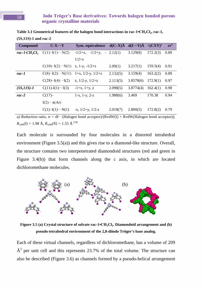
Iodo Tröger’s Base derivatives: Towards halogen bonded porous
organic crystalline materials 58
Table 3.1 Geometrical features of the halogen bond interactions in rac-1•CH2Cl2, rac-1,
(5S,11S)-1 and rac-2
Compound C-X···Y Sym. equivalence d(C–X)Å d(I···Y)Å <(CXY)º rra
rac-1·CH2Cl2 C(1)−I(1)···N(2) -1/2+x, -1/2+y, -
1/2+z
2.12(1) 3.129(8) 172.2(3) 0.89
C(10)−I(2)···N(1) x, 1-y, -1/2+z 2.09(1) 3.217(1) 159.5(4) 0.91
rac-1 C(8)−I(2)···N(11) 1+x, 1/2-y, 1/2+z 2.132(5) 3.159(4) 163.2(2) 0.89
C(28)−I(4)···I(2) x, 1/2-y, 1/2+z 2.113(5) 3.8578(6) 172.9(1) 0.97
(5S,11S)-1 C(11)-I(1)···I(3) -1+x, 1+y, z 2.098(5) 3.8774(4) 162.4(1) 0.98
rac-2 C(17)–
I(2)···π(Ar)
1-x, 1-y, 2-z 1.988(6) 3.469 170.38 0.94
C(1)–I(1)···N(1) -x, 1/2+y, 1/2-z 2.018(7) 2.800(5) 172.8(2) 0.79
a) Reduction ratio, rr = dI···(Halogen bond acceptor)/(RvdW(I) + RvdW(Halogen bond acceptor));
RvdW(I) = 1.98 Å, RvdW(N) = 1.55 Å [24]
Each molecule is surrounded by four molecules in a distorted tetrahedral
environment (Figure 3.5(a)) and this gives rise to a diamond-like structure. Overall,
the structure contains two interpenetrated diamondoid structures (red and green in
Figure 3.4(b)) that form channels along the c axis, in which are located
dichloromethane molecules.
Figure 3.5 (a) Crystal structure of solvate rac-1•CH2Cl2. Diamondoid arrangement and (b)
pseudo-tetrahedral environment of the 2,8-diiodo Tröger’s base analog.
Each of these virtual channels, regardless of dichloromethane, has a volume of 209
Å3 per unit cell and this represents 23.7% of the total volume. The structure can
also be described (Figure 3.6) as channels formed by a pseudo-helical arrangement
(a) (b)
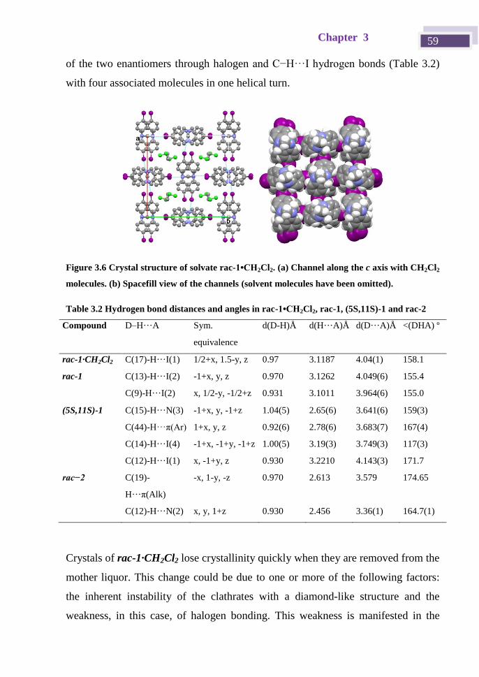
Chapter 3 59
of the two enantiomers through halogen and C−H···I hydrogen bonds (Table 3.2)
with four associated molecules in one helical turn.
Figure 3.6 Crystal structure of solvate rac-1•CH2Cl2. (a) Channel along the c axis with CH2Cl2
molecules. (b) Spacefill view of the channels (solvent molecules have been omitted).
Table 3.2 Hydrogen bond distances and angles in rac-1•CH2Cl2, rac-1, (5S,11S)-1 and rac-2
Compound D–H···A Sym.
equivalence
d(D-H)Å d(H···A)Å d(D···A)Å <(DHA) º
rac-1·CH2Cl2 C(17)-H···I(1) 1/2+x, 1.5-y, z 0.97 3.1187 4.04(1) 158.1
rac-1 C(13)-H···I(2) -1+x, y, z 0.970 3.1262 4.049(6) 155.4
C(9)-H···I(2) x, 1/2-y, -1/2+z 0.931 3.1011 3.964(6) 155.0
(5S,11S)-1 C(15)-H···N(3) -1+x, y, -1+z 1.04(5) 2.65(6) 3.641(6) 159(3)
C(44)-H···π(Ar) 1+x, y, z 0.92(6) 2.78(6) 3.683(7) 167(4)
C(14)-H···I(4) -1+x, -1+y, -1+z 1.00(5) 3.19(3) 3.749(3) 117(3)
C(12)-H···I(1) x, -1+y, z 0.930 3.2210 4.143(3) 171.7
rac−2 C(19)-
H···π(Alk)
-x, 1-y, -z 0.970 2.613 3.579 174.65
C(12)-H···N(2) x, y, 1+z 0.930 2.456 3.36(1) 164.7(1)
Crystals of rac-1·CH2Cl2 lose crystallinity quickly when they are removed from the
mother liquor. This change could be due to one or more of the following factors:
the inherent instability of the clathrates with a diamond-like structure and the
weakness, in this case, of halogen bonding. This weakness is manifested in the
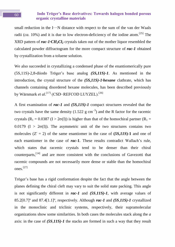
Iodo Tröger’s Base derivatives: Towards halogen bonded porous
organic crystalline materials 60
small reduction in the I···N distance with respect to the sum of the van der Waals
radii (ca. 10%) and it is due to low electron-deficiency of the iodine atom.[25]
The
XRD pattern of rac-1·CH2Cl2 crystals taken out of the mother liquor resembled the
calculated powder diffractogram for the more compact structure of rac-1 obtained
by crystallization from a toluene solution.
We also succeeded in crystallizing a condensed phase of the enantiomerically pure
(5S,11S)-2,8-diiodo Tröger’s base analog (5S,11S)-1. As mentioned in the
introduction, the crystal structure of the (5S,11S)-1·hexane clathrate, which has
channels containing disordered hexane molecules, has been described previously
by Wärnmark et al.[17]
(CSD− E COD LUYZEL).[26]
A first examination of rac-1 and (5S,11S)-1 compact structures revealed that the
two crystals have the same density (1.522 g cm–3
) and the R factor for the racemic
crystals (R1 = 0.0387 (I > 2(I)) is higher than that of the homochiral partner (R1 =
0.0179 (I > 2(I)). The asymmetric unit of the two structures contains two
molecules (Z' = 2) of the same enantiomer in the case of (5S,11S)-1 and one of
each enantiomer in the case of rac-1. These results contradict allach’s rule,
which states that racemic crystals tend to be denser than their chiral
counterparts,[14]
and are more consistent with the conclusions of Gavezotti that
racemic compounds are not necessarily more dense or stable than the homochiral
ones.[27]
Tröger’s base has a rigid conformation despite the fact that the angle between the
planes defining the chiral cleft may vary to suit the solid state packing. This angle
is not significantly different in rac-1 and (5S,11S)-1, with average values of
85.2[0.7]º and 87.4[1.1]º, respectively. Although rac-1 and (5S,11S)-1 crystallized
in the monoclinic and triclinic systems, respectively, their supramolecular
organizations show some similarities. In both cases the molecules stack along the a
axis: in the case of (5S,11S)-1 the stacks are formed in such a way that they result
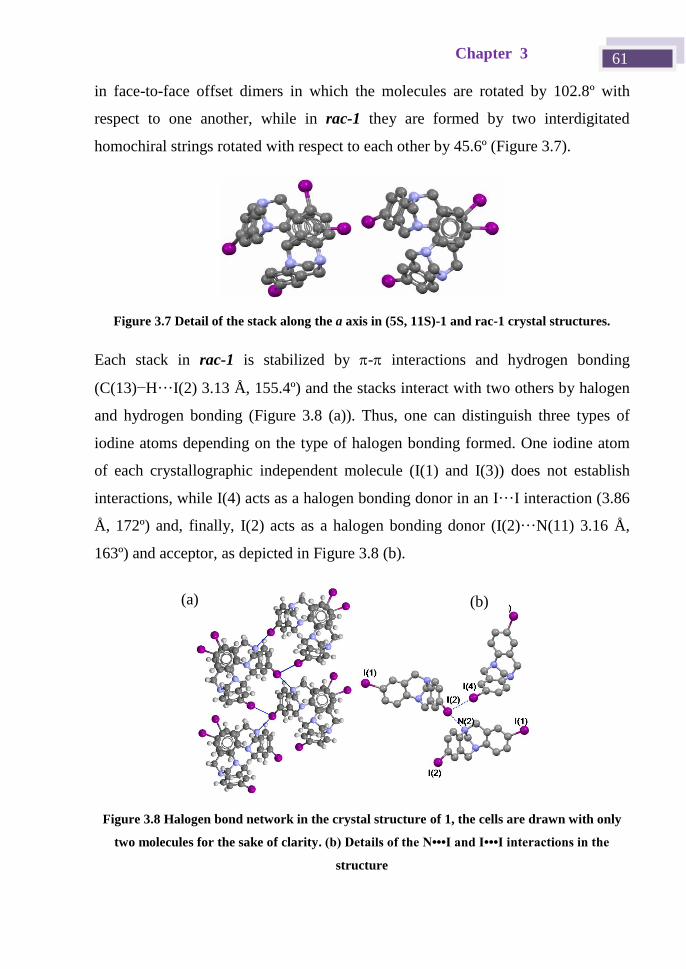
Chapter 3 61
in face-to-face offset dimers in which the molecules are rotated by 102.8º with
respect to one another, while in rac-1 they are formed by two interdigitated
homochiral strings rotated with respect to each other by 45.6º (Figure 3.7).
Figure 3.7 Detail of the stack along the a axis in (5S, 11S)-1 and rac-1 crystal structures.
Each stack in rac-1 is stabilized by - interactions and hydrogen bonding
(C(13)−H···I(2) 3.13 Å, 155.4º) and the stacks interact with two others by halogen
and hydrogen bonding (Figure 3.8 (a)). Thus, one can distinguish three types of
iodine atoms depending on the type of halogen bonding formed. One iodine atom
of each crystallographic independent molecule (I(1) and I(3)) does not establish
interactions, while I(4) acts as a halogen bonding donor in an I···I interaction (3.86
Å, 172º) and, finally, I(2) acts as a halogen bonding donor (I(2)···N(11) 3.16 Å,
163º) and acceptor, as depicted in Figure 3.8 (b).
Figure 3.8 Halogen bond network in the crystal structure of 1, the cells are drawn with only
two molecules for the sake of clarity. (b) Details of the N•••I and I•••I interactions in the
structure
(b) (a)
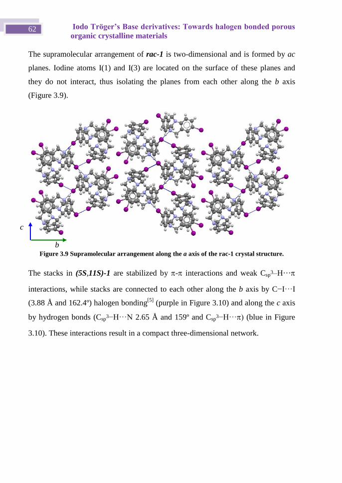
Iodo Tröger’s Base derivatives: Towards halogen bonded porous
organic crystalline materials 62
The supramolecular arrangement of rac-1 is two-dimensional and is formed by ac
planes. Iodine atoms I(1) and I(3) are located on the surface of these planes and
they do not interact, thus isolating the planes from each other along the b axis
(Figure 3.9).
Figure 3.9 Supramolecular arrangement along the a axis of the rac-1 crystal structure.
The stacks in (5S,11S)-1 are stabilized by - interactions and weak Csp3–H···
interactions, while stacks are connected to each other along the b axis by C−I···I
(3.88 Å and 162.4º) halogen bonding[5]
(purple in Figure 3.10) and along the c axis
by hydrogen bonds (Csp3−H··· 2.65 Å and 159º and Csp
3−H··· (blue in Figure
3.10). These interactions result in a compact three-dimensional network.
b
c
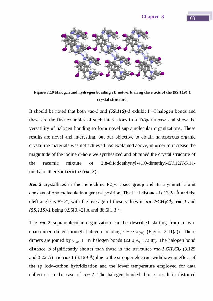
Chapter 3 63
Figure 3.10 Halogen and hydrogen bonding 3D network along the a axis of the (5S,11S)-1
crystal structure.
It should be noted that both rac-1 and (5S,11S)-1 exhibit I···I halogen bonds and
these are the first examples of such interactions in a Tröger’s base and show the
versatility of halogen bonding to form novel supramolecular organizations. These
results are novel and interesting, but our objective to obtain nanoporous organic
crystalline materials was not achieved. As explained above, in order to increase the
magnitude of the iodine -hole we synthesized and obtained the crystal structure of
the racemic mixture of 2,8-diiodoethynyl-4,10-dimethyl-6H,12H-5,11-
methanodibenzodiazocine (rac-2).
Rac-2 crystallizes in the monoclinic P21/c space group and its asymmetric unit
consists of one molecule in a general position. The I···I distance is 13.28 Å and the
cleft angle is 89.2º, with the average of these values in rac-1·CH2Cl2, rac-1 and
(5S,11S)-1 being 9.95[0.42] Å and 86.6[1.3]º.
The rac-2 supramolecular organization can be described starting from a two-
enantiomer dimer through halogen bonding C−I···(Ar) (Figure 3.11(a)). These
dimers are joined by Csp−I···N halogen bonds (2.80 Å, 172.8º). The halogen bond
distance is significantly shorter than those in the structures rac-1·CH2Cl2 (3.129
and 3.22 Å) and rac-1 (3.159 Å) due to the stronger electron-withdrawing effect of
the sp iodo-carbon hybridization and the lower temperature employed for data
collection in the case of rac-2. The halogen bonded dimers result in distorted
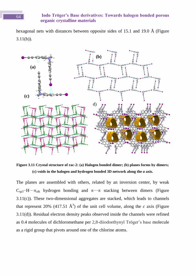
Iodo Tröger’s Base derivatives: Towards halogen bonded porous
organic crystalline materials 64
hexagonal nets with distances between opposite sides of 15.1 and 19.0 Å (Figure
3.11(b)).
Figure 3.11 Crystal structure of rac-2: (a) Halogen bonded dimer; (b) planes forms by dimers;
(c) voids in the halogen and hydrogen bonded 3D network along the a axis.
The planes are assembled with others, related by an inversion center, by weak
Csp3−H···alk hydrogen bonding and ··· stacking between dimers (Figure
3.11(c)). These two-dimensional aggregates are stacked, which leads to channels
that represent 20% (417.51 Å3) of the unit cell volume, along the c axis (Figure
3.11(d)). Residual electron density peaks observed inside the channels were refined
as 0.4 molecules of dichloromethane per 2,8-diiodoethynyl Tröger’s base molecule
as a rigid group that pivots around one of the chlorine atoms.
(b)
(c)
(a)
d)
Chapter 3 65
3.5 Conclusions
The iodo Tröger’s base derivatives 2,8-diiodo-4,10-dimethyl-6H,12H-5,11-
methano-dibenzodiazocine rac-1 and (5S,11S)-1 are suitable building blocks to
obtain clathrate suprastructures and compact crystalline materials. Thus, we
obtained a porous diamondoid-type structure, based on I···N halogen bonds, when
rac-1 was crystallized from dichloromethane. The supramolecular architectures of
compact structures of rac-1 and (5S,11S)-1 have some similarities but the halogen
bond plays a different role in each case. In rac-1 N···I and I···I halogen bonds are
observed, whereas in (5S,11S)-1 only I···I is present. These are the first structures
of iodo Tröger’s base derivatives that have iodine···iodine interactions.
In contrast to the above, Tröger’s base derivative 2,8-diiodoethynyl-4,10-dimethyl-
6H,12H-5,11-methanodibenzodiazocine (rac-2) crystallizes in the monoclinic P21/c
space group and has nanometric channels that represent 20% of the cell volume and
these are occupied by disordered solvent molecules. The two iodoethynyl groups
behave as strong halogen bond donors, as evidenced by the I···N and I···π(Ar)
interaction distances. These interactions give rise to a dimeric unit formed by the
two enantiomers (5S,11S)-2 and (5R,11R)-2, which play a fundamental role in the
formation of a nanoporous crystalline organization.
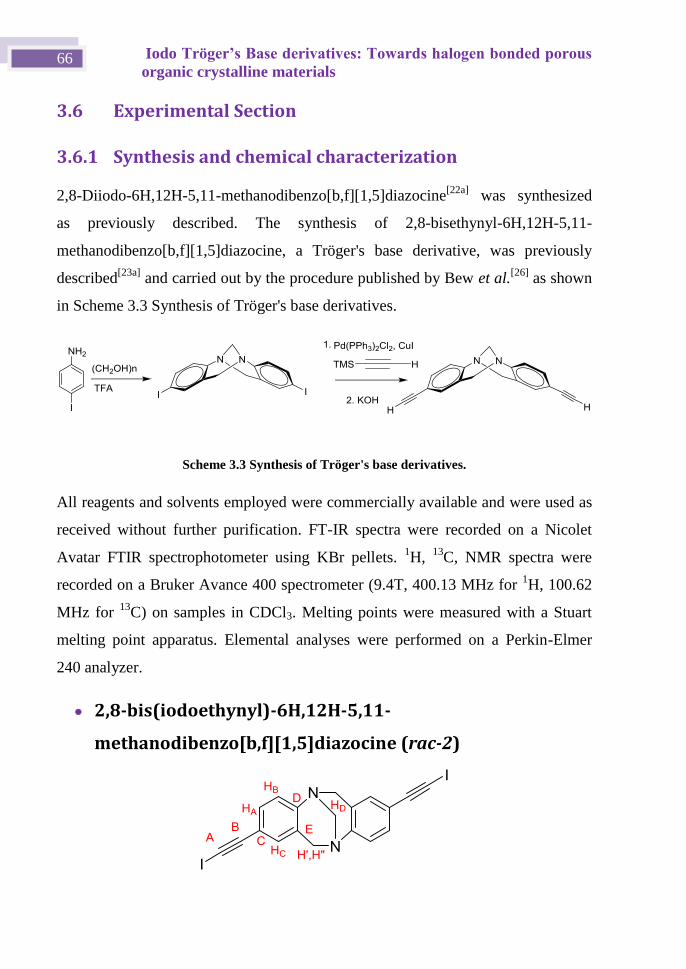
Iodo Tröger’s Base derivatives: Towards halogen bonded porous
organic crystalline materials 66
3.6 Experimental Section
3.6.1 Synthesis and chemical characterization
2,8-Diiodo-6H,12H-5,11-methanodibenzo[b,f][1,5]diazocine[22a]
was synthesized
as previously described. The synthesis of 2,8-bisethynyl-6H,12H-5,11-
methanodibenzo[b,f][1,5]diazocine, a Tröger's base derivative, was previously
described[23a]
and carried out by the procedure published by Bew et al.[26]
as shown
in Scheme 3.3 Synthesis of Tröger's base derivatives.
Scheme 3.3 Synthesis of Tröger's base derivatives.
All reagents and solvents employed were commercially available and were used as
received without further purification. FT-IR spectra were recorded on a Nicolet
Avatar FTIR spectrophotometer using KBr pellets. 1H,
13C, NMR spectra were
recorded on a Bruker Avance 400 spectrometer (9.4T, 400.13 MHz for 1H, 100.62
MHz for 13
C) on samples in CDCl3. Melting points were measured with a Stuart
melting point apparatus. Elemental analyses were performed on a Perkin-Elmer
240 analyzer.
2,8-bis(iodoethynyl)-6H,12H-5,11-
methanodibenzo[b,f][1,5]diazocine (rac-2)
Chapter 3 67
To a stirred solution of 2,8-bis(trimethylsilylethynyl)-6H,12H-5,11-
methanodibenzo[b,f][1,5]diazocine (415 mg, 1 mmol) in DMF (30 mL) was added
silver(I) nitrate (3.9 mg, 0.023 mmol). The mixture was stirred for 30 min. Under
an argon atmosphere and at 0 ºC, N-iodosuccinimide was slowly added (517.3 mg,
2.3 mmol). The mixture was stirred for 5 hours, protected from light, and the
mixture was then filtered and added over water. The product was extracted 3 times
with diethyl ether and cooled until a precipitate formed. The solid was filtered off
and the ether was evaporated. Yield: 434 mg, 83%.
NMR (400 MHz, CDCl3) δ ppm: 7.22 (dd, J = 8.3, 1.9 Hz, 1H, HA), 7.04 (d, J =
8.3 Hz, 1H, HB), 7.00 (d, J = 1.9 Hz, 1H, HC), 4.62 (d, J = 16.7 Hz, 1H, H’), 4.26
(s, 1H, HD), 4.10 (d, J = 16.7 Hz, 1H, H”). 13
C NMR (101 MHz, CDCl3) δ ppm:
29.86 (A), 58.55 (CH’, H”), 66.83 (CHD), 93.85 (B), 119.11 (C), 125.05 (CHB),
127.84 (E), 131.20 (CHA), 131.57 (CHC), 148.68 (D).
3.6.2 X-ray monocrystal diffraction
X-ray diffraction intensity data were collected on an Oxford-diffraction Xcalibur S
diffractometer. Data were collected with Mo-K ( = 0.71069 Å) radiation. The
software package CrysAlys were used to process data.[28]
Final cell parameters were obtained by global refinement of reflections obtained
from integration of all the frames data. The structures were solved by direct
methods and refined by the full-matrix method based on F2 using the program
SHELXTL.[29]
The non-hydrogen atoms of structures were refined anisotropically,
the hydrogen atoms were observed in difference electro density maps and refined
isotropically or placed in idealized positions and refined as riding atoms. Solvent
molecules were modelled as isotropic dichloromethane and finally SQUEEZE[30]
was applied. The crystal parameters and basic information relating data collection
and structure refinement for the compounds are summarized in Table 3..
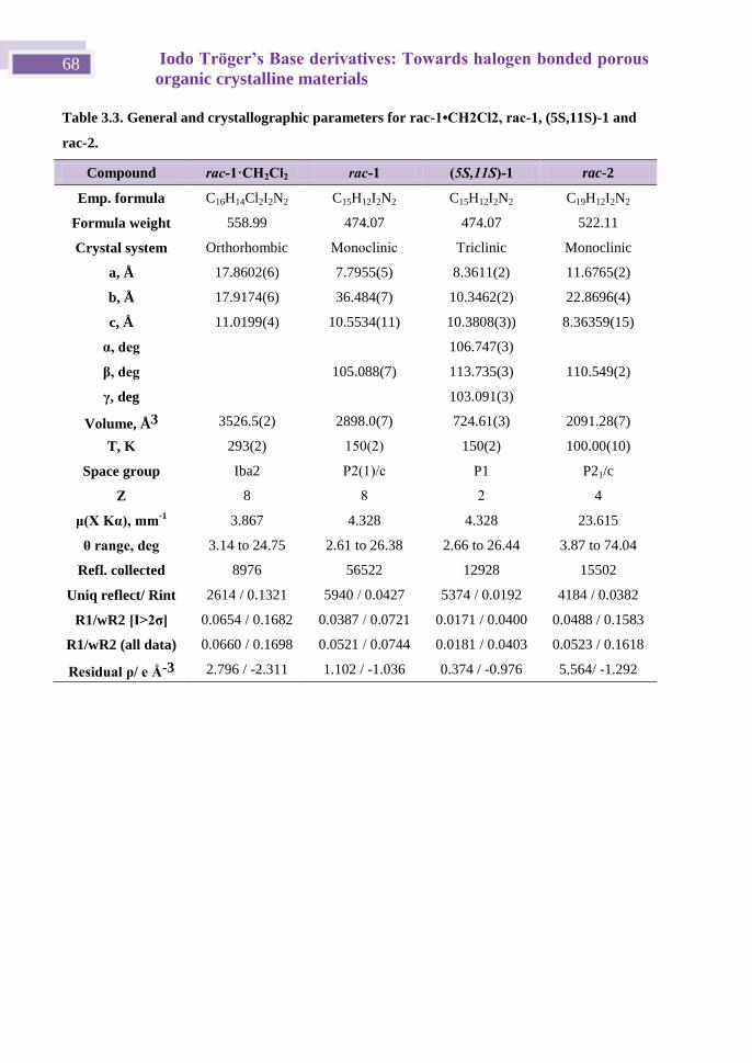
Iodo Tröger’s Base derivatives: Towards halogen bonded porous
organic crystalline materials 68
Table 3.3. General and crystallographic parameters for rac-1•CH2Cl2, rac-1, (5S,11S)-1 and
rac-2.
Compound rac-1·CH2Cl2 rac-1 (5S,11S)-1 rac-2
Emp. formula C16H14Cl2I2N2 C15H12I2N2 C15H12I2N2 C19H12I2N2
Formula weight 558.99 474.07 474.07 522.11
Crystal system Orthorhombic Monoclinic Triclinic Monoclinic
a, Å 17.8602(6) 7.7955(5) 8.3611(2) 11.6765(2)
b, Å 17.9174(6) 36.484(7) 10.3462(2) 22.8696(4)
c, Å 11.0199(4) 10.5534(11) 10.3808(3)) 8.36359(15)
α, deg 106.747(3)
β, deg 105.088(7) 113.735(3) 110.549(2)
γ, deg 103.091(3)
Volume, Å3 3526.5(2) 2898.0(7) 724.61(3) 2091.28(7)
T, K 293(2) 150(2) 150(2) 100.00(10)
Space group Iba2 P2(1)/c P1 P21/c
Z 8 8 2 4
μ(X Kα), mm-1 3.867 4.328 4.328 23.615
θ range, deg 3.14 to 24.75 2.61 to 26.38 2.66 to 26.44 3.87 to 74.04
Refl. collected 8976 56522 12928 15502
Uniq reflect/ Rint 2614 / 0.1321 5940 / 0.0427 5374 / 0.0192 4184 / 0.0382
R1/wR2 [I>2σ] 0.0654 / 0.1682 0.0387 / 0.0721 0.0171 / 0.0400 0.0488 / 0.1583
R1/wR2 (all data) 0.0660 / 0.1698 0.0521 / 0.0744 0.0181 / 0.0403 0.0523 / 0.1618
Residual ρ/ e Å-3 2.796 / -2.311 1.102 / -1.036 0.374 / -0.976 5.564/ -1.292
Chapter 3 69
3.7 Bibliography
[1] Z. Wang and Y. Wang, Macromolecules 2016, 49, 182-191.
[2] W. Li, Y. Yang, J. K. Weber, G. Zhang and R. Zhou, ACS Nano 2016, 10, 1829-1835.
[3] Z. Yang, I. Moriguchi and N. Nakashima, ACS Appl Mater Interfaces 2016, 8, 9030-9036.
[4] L. F. Lai, J. A. Love, A. Sharenko, J. E. Coughlin, V. Gupta, S. Tretiak, T.-Q. Nguyen, W.-Y.
Wong and G. C. Bazan, J Am Chem Soc 2014, 136, 5591-5594.
[5] G. R. Desiraju, J Am Chem Soc 2013, 135, 9952-9967.
[6] R. Dawson, A. I. Cooper and D. J. Adams, Prog. Polym. Sci. 2012, 37, 530-563.
[7] S. Das, P. Heasman, T. Ben and S. Qiu, Chem Rev 2017, 117, 1515-1563.
[8] M. E. Davis, Chemistry of Materials 2014, 26, 239-245.
[9] L. Sun, M. G. Campbell and M. Dincă, Angew. Chem., Int. Ed. 2016, 55, 3566-3579.
[10] a) X. Du, Y. L. Sun, B. E. Tan, Q. F. Teng, X. J. Yao, C. Y. Su and W. Wang, Chem. Commun.
2010, 46, 970-972; b) M. Carta, M. Croad, R. Malpass-Evans, J. C. Jansen, P. Bernardo, G. Clarizia,
K. Friess, M. Lanc and N. B. McKeown, Adv. Mat. 2014, 26, 3526-3531; c) M. Carta, R. Malpass-
Evans, M. Croad, Y. Rogan, J. C. Jansen, P. Bernardo, F. Bazzarelli and N. B. McKeown, Science
2013, 339, 303-307; d) A. Del Regno, A. Gonciaruk, L. Leay, M. Carta, M. Croad, R. Malpass-
Evans, N. B. McKeown and F. R. Siperstein, Ind. Eng. Chem. Res. 2013, 52, 16939-16950; e) Z.-Z.
Yang, H. Zhang, B. Yu, Y. Zhao, G. Ji and Z. Liu, Chem. Commun. 2015, 51, 1271-1274.
[11] a) B. Dolensky, J. Elguero, V. Kral, C. Pardo and M. Valik in Current Tröger's base chemistry,
Vol. 93 (Ed. A. R. Katrizky), Academic Press, 2007, pp. 1-56; b) S. Sergeyev, Helv. Chim. Acta
2009, 92, 415-444; c) O. V. Runarsson, J. Artacho and K. Warnmark, European J. Org. Chem.
2012, 7015-7041.
[12] a) K. Raatikainen, J. Huuskonen, M. Lahtinen, P. Metrangolo and K. Rissanen, Chem.
Commun. 2009, 2160-2162; b) K. Raatikainen and K. Rissanen, Cryst. Growth Des. 2010, 10, 3638-
3646; c) K. Raatikainen and K. Rissanen, CrystEngComm 2011, 13, 6972-6977; d) K. Raatikainen
and K. Rissanen, Chem. Sci. 2012, 3, 1235-1239.
[13] C. S. Arribas, O. F. Wendt, A. P. Sundin, C. J. Carling, R. Wang, R. P. Lemieux and K.
Warnmark, Chem Commun 2010, 46, 4381-4383.
[14] O. Wallach, Justus Liebigs Annalen der Chemie 1895, 286, 90-118.
[15] a) C. S. Arribas, O. F. Wendt, A. P. Sundin, C. J. Carling, R. Y. Wang, R. P. Lemieux and K.
Warnmark, Chem. Commun. 2010, 46, 4381-4383 b) C. Benkh user‐Schunk, B. ezisla, K.
Urbahn, U. Kiehne, J. Daniels, G. Schnakenburg, F. Neese and A. Lützen, ChemPlusChem 2012,
77, 396-403.
[16] M. Faroughi, K.-X. Zhu, P. Jensen, D. C. Craig and A. C. Try, Eur. J. Org. Chem. 2009, 2009,
4266-4272.
[17] C. Solano, O. F. Wendt, A. P. Sundin, C. J. Carling, R. Y. Wang, R. P. Lemieux and K.
Warnmark, Chem. Commun. 2010, 46, 4381-4383.
[18] R. Thaimattam, C. V. K. Sharma, A. Clearfield and G. R. Desiraju, Cryst. Growth Des. 2001,
1, 103-106.
[19] a) C. B. Aakeroey, M. Baldrighi, J. Desper, P. Metrangolo and G. Resnati, Chem. Eur. J. 2013,
19, 16240-16247; b) J.-Y. Le Questel, C. Laurence and J. Graton, CrystEngComm 2013, 15, 3212-
3221; c) E. Bosch, Cryst. Growth Des. 2014, 14, 126.
[20] W. Wu and H. Jiang, Acc. Chem. Res. 2014, 47, 2483-2504.
[21] a) H. M. Yamamoto, J. I. Yamaura and R. Kato, J. Am. Chem. Soc. 1998, 120, 5905-5913; b)
H. M. Yamamoto, R. Maeda, J. I. Yamaura and R. Kato, J. Mater. Chem. 2001, 11, 1034; c) H. M.
Yamamoto, Y. Kosaka, R. Maeda, J. Yamaura, A. Nakao, T. Nakamura and R. Kato, ACS Nano
2008, 2, 143-155; d) A. Sun, J. W. Lauher and N. S. Goroff, Science 2006, 312, 1030; e) L. Luo, C.
Wilhelm, A. Sun, C. P. Grey, J. W. Lauher and N. S. Goroff, J. Am. Chem. Soc. 2008, 130, 7702; f)
J. Lieffrig, O. Jeannin and M. Fourmigué, J. Am. Chem. Soc. 2013, 135, 6200; g) C. Perkins, S.
Libri, H. Adams and L. Brammer, CrystEngComm 2012, 14, 3033-3038.
Iodo Tröger’s Base derivatives: Towards halogen bonded porous
organic crystalline materials 70
[22] a) J. Jensen and K. Warnmark, Synthesis 2001, 1873-1877; b) A. Hansson, J. Jensen, O. F.
Wendt and K. Wärnmark, Eur. J. Org. Chem. 2003, 3179 - 3188.
[23] a) J. Jensen, M. Strozyk and K. Warnmark, Synthesis 2002, 2761-2765; b) U. Kiehne and A.
Lutzen, Synthesis 2004, 1687-1695.
[24] A. Bondi, J. Phys. Chem. 1964, 68, 441.
[25] T. Kitazawa, Chem. Commun. 1999, 891-892.
[26] S. P. Bew, L. Legentil, V. Scholier and S. V. Sharma, Chem Commun 2007, 389-391.
[27] A. Gavezzotti and S. Rizzato, J. Org. Chem. 2014, 79, 4809-4816.
[28] in CrysAlis Vol. 2006.
[29] G. M. Sheldrick in SHELXTL, Vol. Brucker Analytical X-ray Systems, Madison, WI, 1997.
[30] A. L. Spek, Acta Crystallogr., Sect. D: Biol. Crystallogr. 2009, 65, 148-155.
Chapter 4 Supramolecular chemistry:
Crystal engineering

Chapter 4 73
4.1 Introduction
Crystal engineering mainly uses two strategies that involve the formation of
homomeric or heteromeric networks to guide the arrangement adopted by the
individual molecules in the solid state. This is the key for material performance in
all molecular organic devices.[1]
The first approach requires the acceptor and donor
sites to be present in the same molecule, which minimizes interference due to
competition between different interactions.[2]
In chapters 2 and 3 we presented the
homomeric networks formed by iodoethynyl derivatives. The second strategy
consists of the cocrystallization of two or more components that interact by
hydrogen bonding, halogen bonding, π···π stacking or a combination of such
interactions. The advantage of this strategy is that it allows new architectures to be
obtained in a versatile way using previously described compounds.[3]
One of the objectives of crystal engineering is to control the dimensionality of the
supramolecular architecture, ranging from isolated aggregates (0), chains, ribbons
(1D), rosettes (2D) to three-dimensional (3D) crystal motifs. It is possible to
construct by cocrystallization architectures of different dimensionalities by
increasing the number of donor/acceptor sites and by orienting them in such a way
that two or three synthetic vectors remain more or less orthogonal to each other.
Different strategies to obtain 2D structures are shown in Figure 4.1.[4]
There is still
a lack of 2D or 3D structures and this could be due to the synthetic challenges or
problems with crystal growth.
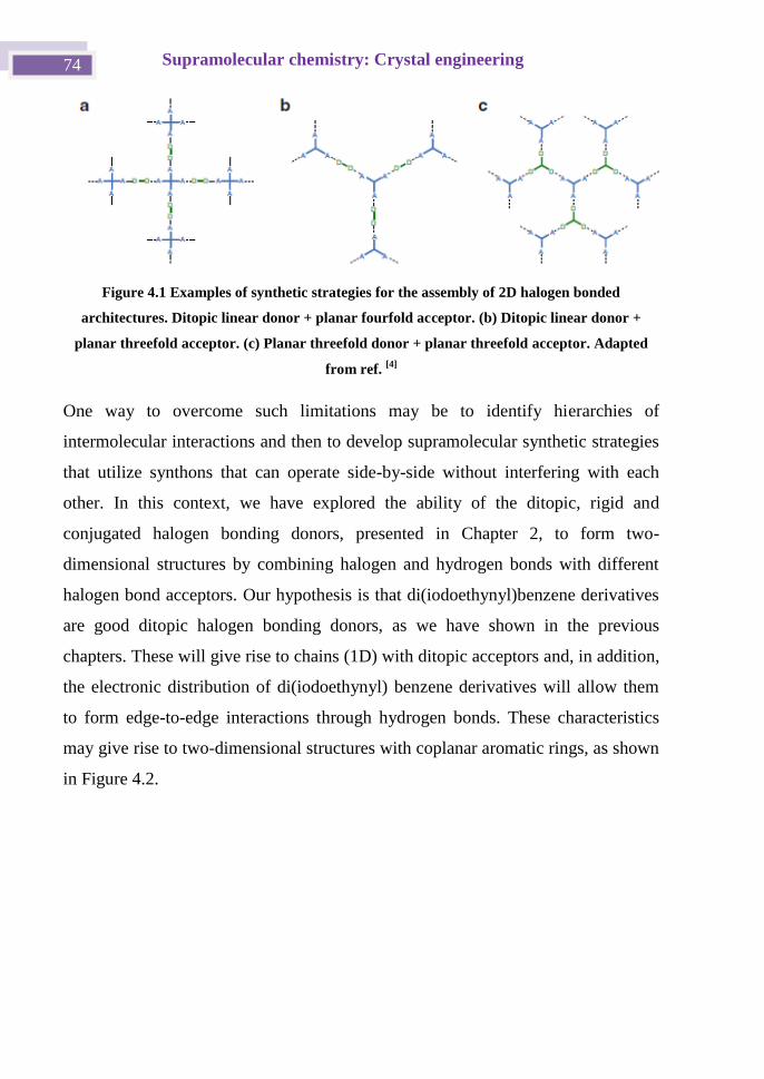
Supramolecular chemistry: Crystal engineering 74
Figure 4.1 Examples of synthetic strategies for the assembly of 2D halogen bonded
architectures. Ditopic linear donor + planar fourfold acceptor. (b) Ditopic linear donor +
planar threefold acceptor. (c) Planar threefold donor + planar threefold acceptor. Adapted
from ref. [4]
One way to overcome such limitations may be to identify hierarchies of
intermolecular interactions and then to develop supramolecular synthetic strategies
that utilize synthons that can operate side-by-side without interfering with each
other. In this context, we have explored the ability of the ditopic, rigid and
conjugated halogen bonding donors, presented in Chapter 2, to form two-
dimensional structures by combining halogen and hydrogen bonds with different
halogen bond acceptors. Our hypothesis is that di(iodoethynyl)benzene derivatives
are good ditopic halogen bonding donors, as we have shown in the previous
chapters. These will give rise to chains (1D) with ditopic acceptors and, in addition,
the electronic distribution of di(iodoethynyl) benzene derivatives will allow them
to form edge-to-edge interactions through hydrogen bonds. These characteristics
may give rise to two-dimensional structures with coplanar aromatic rings, as shown
in Figure 4.2.
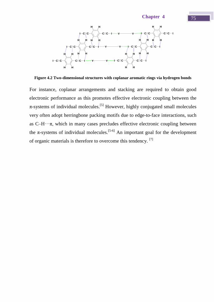
Chapter 4 75
Y YCC CC
H H
H
I
H
I
CC CC
H H
H
I
H
I
CC CC
H H
H
I
H
I
CC CC
H H
H
I
H
I
CC CC
H H
H
I
H
I
CC CC
H H
H
I
H
IY Y
Y Y
Figure 4.2 Two-dimensional structures with coplanar aromatic rings via hydrogen bonds
For instance, coplanar arrangements and stacking are required to obtain good
electronic performance as this promotes effective electronic coupling between the
π-systems of individual molecules.[5]
However, highly conjugated small molecules
very often adopt herringbone packing motifs due to edge-to-face interactions, such
as C–H···π, which in many cases precludes effective electronic coupling between
the π-systems of individual molecules.[5-6]
An important goal for the development
of organic materials is therefore to overcome this tendency. [7]
Supramolecular chemistry: Crystal engineering 76
4.2 Objectives and work plan
In order to exemplify this strategy we employed as halogen bond donors 1,4-
bis(iodoethynyl)benzene (pBIEB), 1,4-bis(bromoethynyl)benzene (pBBrEB), and
1,3-bis(iodoethynyl)benzene (mBIEB). We have divided this chapter into two
sections. The first section concerns the studies with halogen bonding acceptors that
contain nitrogen or oxygen atoms (halogen bonding cocrystals, section 4.3) and the
second section covers the use of the bromide anion as an acceptor (halogen
bonding salts, section 4.4).
Chapter 4 77
4.3 Halogen bonding cocrystals
4.3.1 Previous works
The remarkable directionality of halogen bonding allows the structure and
geometry of the resulting supramolecular architectures to be predicted, with a
reasonably high degree of accuracy, from the structure and geometry of the self-
assembling elements. There are numerous examples in the literature showing that
when bidentate halogen bonding donors self-assemble with bidentate halogen
bonding acceptors, infinite chains are formed in which the donor and acceptor
alternate along the chains. The shape of these infinite chains predictably depends
on the structure of the starting compounds. Thus, if donor and acceptor sites are
colinear, linear copolymers are obtained (Figure 4.3a), e.g., 1,4-
diiodotetrafluorobenzene·4,4'-bipyridine[8]
and 1,4-diiodotetrafluorobenzene·1,4-
diazabicyclo(2.2.2)octane cocrystals.[9]
Staggered infinite chains are formed when
the binding sites are parallel but not colinear (Figure 4.3b) and, when the binding
sites form an angle, the resulting self-assembled chains adopt a zig-zag
arrangement (Figure 4.3c).
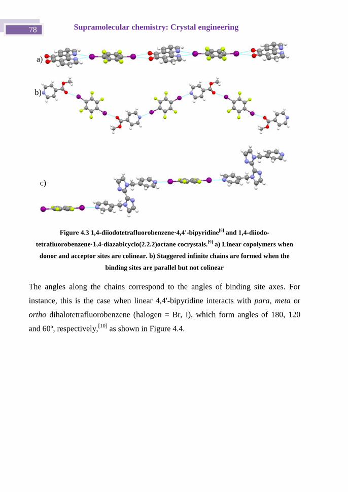
Supramolecular chemistry: Crystal engineering 78
Figure 4.3 1,4-diiodotetrafluorobenzene·4,4'-bipyridine[8]
and 1,4-diiodo-
tetrafluorobenzene·1,4-diazabicyclo(2.2.2)octane cocrystals.[9]
a) Linear copolymers when
donor and acceptor sites are colinear. b) Staggered infinite chains are formed when the
binding sites are parallel but not colinear
The angles along the chains correspond to the angles of binding site axes. For
instance, this is the case when linear 4,4'-bipyridine interacts with para, meta or
ortho dihalotetrafluorobenzene (halogen = Br, I), which form angles of 180, 120
and 60º, respectively,[10]
as shown in Figure 4.4.
a)
b)
c)
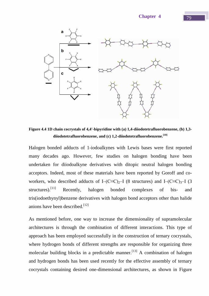
Chapter 4 79
Figure 4.4 1D chain cocrystals of 4,4'-bipyridine with (a) 1,4-diiodotetrafluorobenzene, (b) 1,3-
diiodotetrafluorobenzene, and (c) 1,2-diiodotetrafluorobenzene.[10]
Halogen bonded adducts of 1-iodoalkynes with Lewis bases were first reported
many decades ago. However, few studies on halogen bonding have been
undertaken for diiodoalkyne derivatives with ditopic neutral halogen bonding
acceptors. Indeed, most of these materials have been reported by Goroff and co-
workers, who described adducts of I–(C≡C)2–I (8 structures) and I–(C≡C)3–I (3
structures).[11]
Recently, halogen bonded complexes of bis- and
tris(iodoethynyl)benzene derivatives with halogen bond acceptors other than halide
anions have been described.[12]
As mentioned before, one way to increase the dimensionality of supramolecular
architectures is through the combination of different interactions. This type of
approach has been employed successfully in the construction of ternary cocrystals,
where hydrogen bonds of different strengths are responsible for organizing three
molecular building blocks in a predictable manner.[13]
A combination of halogen
and hydrogen bonds has been used recently for the effective assembly of ternary
cocrystals containing desired one-dimensional architectures, as shown in Figure
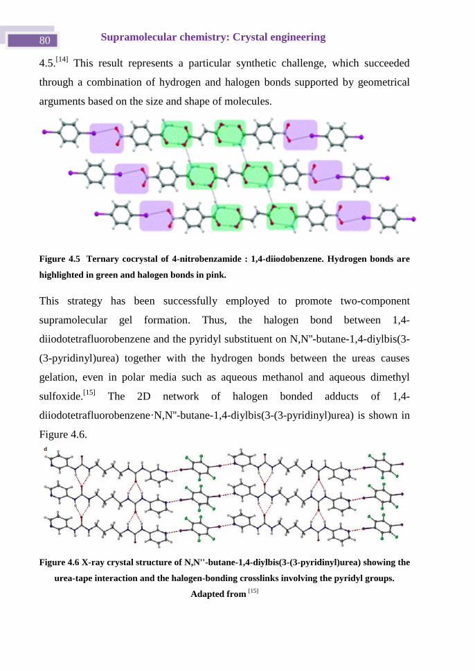
Supramolecular chemistry: Crystal engineering 80
4.5.[14]
This result represents a particular synthetic challenge, which succeeded
through a combination of hydrogen and halogen bonds supported by geometrical
arguments based on the size and shape of molecules.
Figure 4.5 Ternary cocrystal of 4-nitrobenzamide : 1,4-diiodobenzene. Hydrogen bonds are
highlighted in green and halogen bonds in pink.
This strategy has been successfully employed to promote two-component
supramolecular gel formation. Thus, the halogen bond between 1,4-
diiodotetrafluorobenzene and the pyridyl substituent on N,N''-butane-1,4-diylbis(3-
(3-pyridinyl)urea) together with the hydrogen bonds between the ureas causes
gelation, even in polar media such as aqueous methanol and aqueous dimethyl
sulfoxide.[15]
The 2D network of halogen bonded adducts of 1,4-
diiodotetrafluorobenzene·N,N''-butane-1,4-diylbis(3-(3-pyridinyl)urea) is shown in
Figure 4.6.
Figure 4.6 X-ray crystal structure of N,N''-butane-1,4-diylbis(3-(3-pyridinyl)urea) showing the
urea-tape interaction and the halogen-bonding crosslinks involving the pyridyl groups.
Adapted from [15]
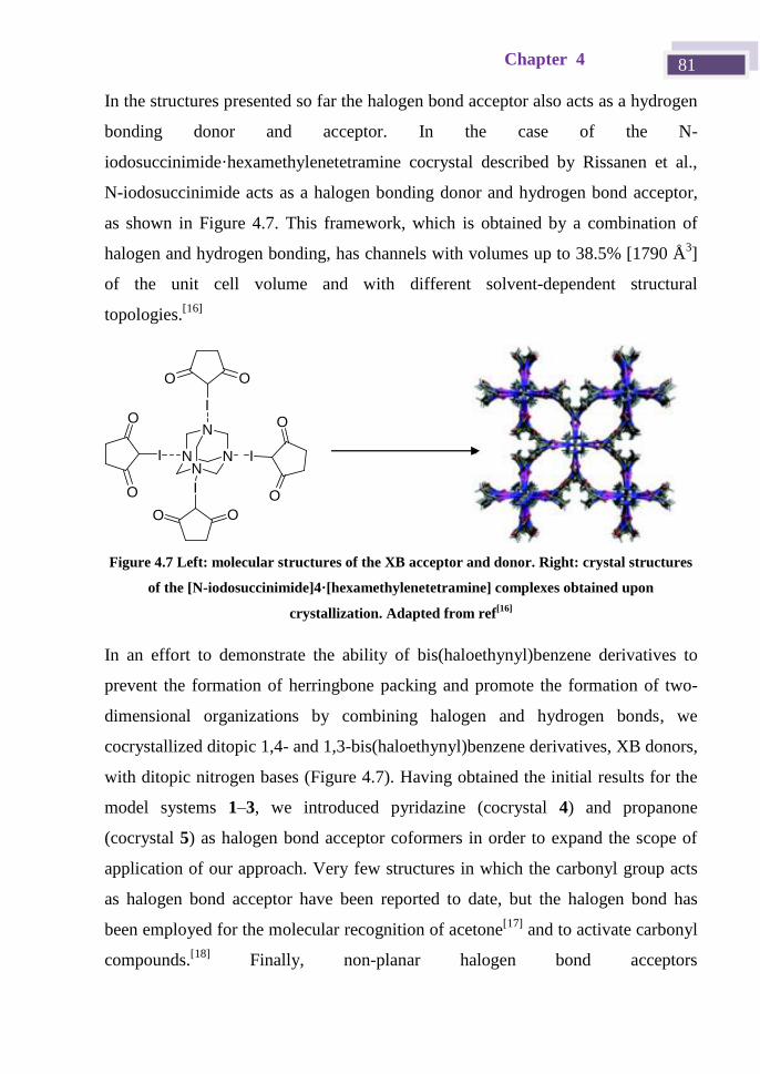
Chapter 4 81
In the structures presented so far the halogen bond acceptor also acts as a hydrogen
bonding donor and acceptor. In the case of the N-
iodosuccinimide·hexamethylenetetramine cocrystal described by Rissanen et al.,
N-iodosuccinimide acts as a halogen bonding donor and hydrogen bond acceptor,
as shown in Figure 4.7. This framework, which is obtained by a combination of
halogen and hydrogen bonding, has channels with volumes up to 38.5% [1790 Å3]
of the unit cell volume and with different solvent-dependent structural
topologies.[16]
I
O
O
NN
N
N
I
O O
I
OO
I
O
O
Figure 4.7 Left: molecular structures of the XB acceptor and donor. Right: crystal structures
of the [N-iodosuccinimide]4·[hexamethylenetetramine] complexes obtained upon
crystallization. Adapted from ref[16]
In an effort to demonstrate the ability of bis(haloethynyl)benzene derivatives to
prevent the formation of herringbone packing and promote the formation of two-
dimensional organizations by combining halogen and hydrogen bonds, we
cocrystallized ditopic 1,4- and 1,3-bis(haloethynyl)benzene derivatives, XB donors,
with ditopic nitrogen bases (Figure 4.7). Having obtained the initial results for the
model systems 1–3, we introduced pyridazine (cocrystal 4) and propanone
(cocrystal 5) as halogen bond acceptor coformers in order to expand the scope of
application of our approach. Very few structures in which the carbonyl group acts
as halogen bond acceptor have been reported to date, but the halogen bond has
been employed for the molecular recognition of acetone[17]
and to activate carbonyl
compounds.[18]
Finally, non-planar halogen bond acceptors
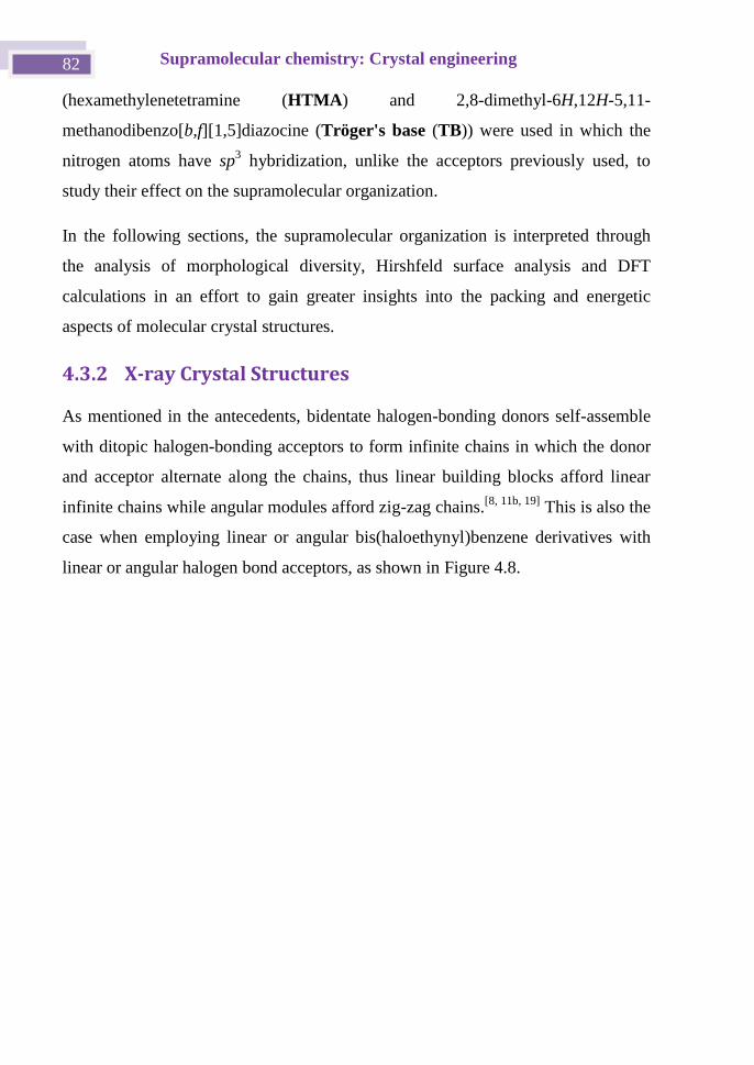
Supramolecular chemistry: Crystal engineering 82
(hexamethylenetetramine (HTMA) and 2,8-dimethyl-6H,12H-5,11-
methanodibenzo[b,f][1,5]diazocine (Tröger's base (TB)) were used in which the
nitrogen atoms have sp3 hybridization, unlike the acceptors previously used, to
study their effect on the supramolecular organization.
In the following sections, the supramolecular organization is interpreted through
the analysis of morphological diversity, Hirshfeld surface analysis and DFT
calculations in an effort to gain greater insights into the packing and energetic
aspects of molecular crystal structures.
4.3.2 X-ray Crystal Structures
As mentioned in the antecedents, bidentate halogen-bonding donors self-assemble
with ditopic halogen-bonding acceptors to form infinite chains in which the donor
and acceptor alternate along the chains, thus linear building blocks afford linear
infinite chains while angular modules afford zig-zag chains.[8, 11b, 19]
This is also the
case when employing linear or angular bis(haloethynyl)benzene derivatives with
linear or angular halogen bond acceptors, as shown in Figure 4.8.
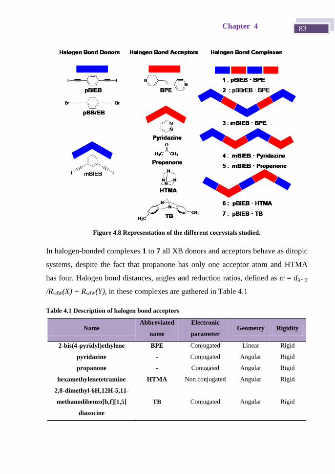
Chapter 4 83
Figure 4.8 Representation of the different cocrystals studied.
In halogen-bonded complexes 1 to 7 all XB donors and acceptors behave as ditopic
systems, despite the fact that propanone has only one acceptor atom and HTMA
has four. Halogen bond distances, angles and reduction ratios, defined as rr = dX···Y
/RvdW(X) + RvdW(Y), in these complexes are gathered in Table 4.1
Table 4.1 Description of halogen bond acceptors
Name Abbreviated
name
Electronic
parameter Geometry Rigidity
2-bis(4-pyridyl)ethylene BPE Conjugated
Linear Rigid
pyridazine - Conjugated Angular Rigid
propanone - Conugated Angular Rigid
hexamethylenetetramine HTMA Non conjugated Angular Rigid
2,8-dimethyl-6H,12H-5,11-
methanodibenzo[b,f][1,5]
diazocine
TB Conjugated Angular Rigid
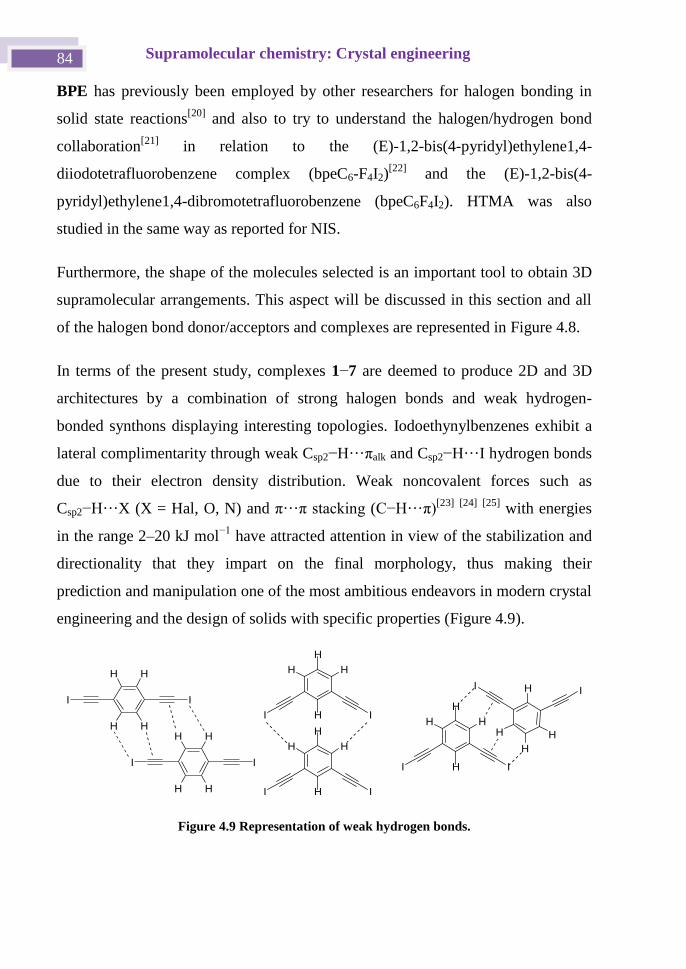
Supramolecular chemistry: Crystal engineering 84
BPE has previously been employed by other researchers for halogen bonding in
solid state reactions[20]
and also to try to understand the halogen/hydrogen bond
collaboration[21]
in relation to the (E)-1,2-bis(4-pyridyl)ethylene1,4-
diiodotetrafluorobenzene complex (bpeC6-F4I2)[22]
and the (E)-1,2-bis(4-
pyridyl)ethylene1,4-dibromotetrafluorobenzene (bpeC6F4I2). HTMA was also
studied in the same way as reported for NIS.
Furthermore, the shape of the molecules selected is an important tool to obtain 3D
supramolecular arrangements. This aspect will be discussed in this section and all
of the halogen bond donor/acceptors and complexes are represented in Figure 4.8.
In terms of the present study, complexes 1−7 are deemed to produce 2D and 3D
architectures by a combination of strong halogen bonds and weak hydrogen-
bonded synthons displaying interesting topologies. Iodoethynylbenzenes exhibit a
lateral complimentarity through weak Csp2−H···πalk and Csp2−H···I hydrogen bonds
due to their electron density distribution. Weak noncovalent forces such as
Csp2−H···X (X = Hal, O, N) and π···π stacking (C−H···π)[23]
[24]
[25]
with energies
in the range 2–20 kJ mol−1
have attracted attention in view of the stabilization and
directionality that they impart on the final morphology, thus making their
prediction and manipulation one of the most ambitious endeavors in modern crystal
engineering and the design of solids with specific properties (Figure 4.9).
I I
H
H H
H
I I
H
H H
H
I I
H
H H
H
II
H
HH
HI I
H H
H H
I I
H H
H H
Figure 4.9 Representation of weak hydrogen bonds.
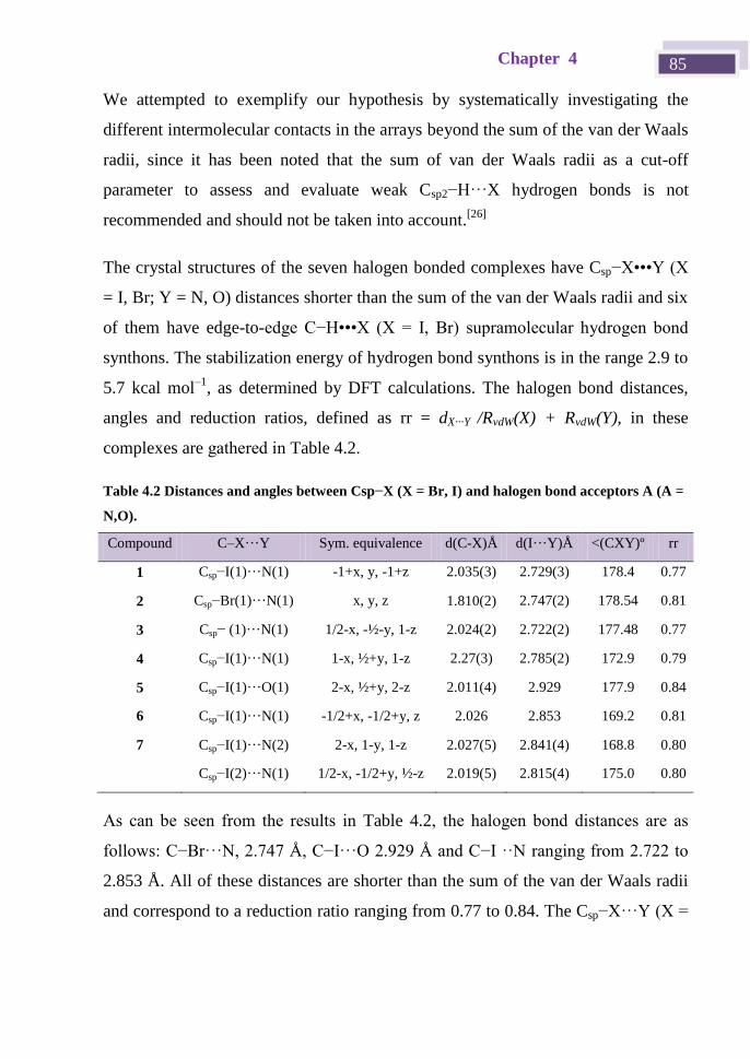
Chapter 4 85
We attempted to exemplify our hypothesis by systematically investigating the
different intermolecular contacts in the arrays beyond the sum of the van der Waals
radii, since it has been noted that the sum of van der Waals radii as a cut-off
parameter to assess and evaluate weak Csp2−H···X hydrogen bonds is not
recommended and should not be taken into account.[26]
The crystal structures of the seven halogen bonded complexes have Csp−X•••Y (X
= I, Br; Y = N, O) distances shorter than the sum of the van der Waals radii and six
of them have edge-to-edge C−H•••X (X = I, Br) supramolecular hydrogen bond
synthons. The stabilization energy of hydrogen bond synthons is in the range 2.9 to
5.7 kcal mol–1
, as determined by DFT calculations. The halogen bond distances,
angles and reduction ratios, defined as rr = dX···Y /RvdW(X) + RvdW(Y), in these
complexes are gathered in Table 4.2.
Table 4.2 Distances and angles between Csp−X (X = Br, I) and halogen bond acceptors A (A =
N,O).
Compound C–X···Y Sym. equivalence d(C-X)Å d(I···Y)Å <(CXY)º rr
1 Csp−I(1)···N(1) -1+x, y, -1+z 2.035(3) 2.729(3) 178.4 0.77
2 Csp−Br(1)···N(1) x, y, z 1.810(2) 2.747(2) 178.54 0.81
3 Csp− (1)···N(1) 1/2-x, -½-y, 1-z 2.024(2) 2.722(2) 177.48 0.77
4 Csp−I(1)···N(1) 1-x, ½+y, 1-z 2.27(3) 2.785(2) 172.9 0.79
5 Csp−I(1)···O(1) 2-x, ½+y, 2-z 2.011(4) 2.929 177.9 0.84
6 Csp−I(1)···N(1) -1/2+x, -1/2+y, z 2.026 2.853 169.2 0.81
7 Csp−I(1)···N(2) 2-x, 1-y, 1-z 2.027(5) 2.841(4) 168.8 0.80
Csp−I(2)···N(1) 1/2-x, -1/2+y, ½-z 2.019(5) 2.815(4) 175.0 0.80
As can be seen from the results in Table 4.2, the halogen bond distances are as
follows: C−Br···N, 2. 4 Å, C−I···O 2. 2 Å and C−I ··N ranging from 2. 22 to
2.853 Å. All of these distances are shorter than the sum of the van der Waals radii
and correspond to a reduction ratio ranging from 0.77 to 0.84. The Csp−X···Y (X =
Supramolecular chemistry: Crystal engineering 86
I, Br; Y = N, O) angles are in all cases almost linear, with values ranging from
168.8 to 178.5º.
The cocrystals 1 to 3 are formed by the same XB acceptor (BPE). Cocrystals 1 and
2 were prepared with two different linear halogen donors, namely an iodo-
derivative (pBIEB) in 1 and a bromo-derivative (pBBrEB) in 2. The halogen
donors in cocrystals 1 and 3 are both iodo-derivatives but with different
geometries, i.e., linear for pBIEB (1) and angular for mBIEB (3). Comparison of
the halogen bonding in 1 (Csp−I···N), 2 (Csp−Br···N) and 3 (Csp−I···N) shows the
same reduction ratio (0.77) in the case of linear (pBIEB, 1) and angular (mBIEB,
3) iodo-based XB donors and a higher ratio in 2 (0.81), where the halogen atom is
bromine (pBBrEB). This latter finding is consistent with halogen bonding
reduction ratios described previously for 1,4-diiodotetrafluorobenzene·BPE
(0.78)[27]
and 1,4-dibromotetrafluorobenzene·BPE (0.84) cocrystals[28]
and also
with the V(r) maximum positive value calculated for the iodo-substituent (172.4 kJ
mol–1
) in 1-iodoethynyl-4-iodobenzene and the less polarizable bromo-substituent
(147.1 kJ mol–1
) in 1-bromoethynyl-4-iodobenzene.[29]
Furthermore, comparison of
the halogen bond distances in the aforementioned BPE cocrystals with the iodo-XB
donors pBIEB and 1,4-diiodotetrafluorobenzene[27]
shows that in both cases the
distances are similar, with values of 2.729 and 2.768 Å, respectively. However, in
the case of bromo-XB donors, the halogen bonding distance is significantly shorter
in cocrystal 2, which contains pBBrEB as the coformer (2.747 Å), than in the 1,4-
dibromotetrafluorobenzene·BPE (2.814 Å) cocrystal. As a consequence, the
bromo-substituent is more strongly affected by a triple bond unit than it is by the
proximity of a perfluorinated benzene ring, thus making the bromoethynyl moiety a
useful XB donor in crystal engineering.[29-30]
Cocrystals 4 and 5 are formed with the angular mBIEB iodo-donor and two
angular ditopic XB acceptors, namely pyridazine and propanone (with sp2
hybridized nitrogen and oxygen, respectively). The halogen bond distance in 4
Chapter 4 87
shows a reduction ratio of 0.79, which is slightly higher than those observed in 1
and 3 – a finding that could be attributed to the low acceptor ability of the
pyridazine due to the effect of the neighboring nitrogen. Cocrystal 5 has a longer
halogen bond distance (Csp−I···O) (2. 2 Å) with a reduction ratio of 0.84. This
distance is slightly longer than those previously described for the Csp−I···Osp2
2.877 Å interaction in the 1-[4-(iodoethynyl)phenyl]ethanone structure.[31]
This fact
may be due to oxygen forming a bifurcated halogen bond in an analogous way to
that described for 4,4'-bis(dimethylamino)benzophenone and dimethylformamide
in halogen-bonding cocrystal structures with 1,4-diiodo-2,3,5,6-
tetrafluorobenzene[32]
and diiodoacetylene,[33]
respectively.
Finally, cocrystals 6 and 7 allowed us to analyze the influence that the nitrogen
atom hybridization has on the XB distance. The halogen bond distances (Csp−I···N)
in these structures, in which the nitrogen atom has sp3
hybridization, are 2.853 Å
(6) and 2.841 Å (7), respectively. Comparison of these distances with those in
compounds 1 (2.729 Å), 3 (2.722 Å) and 4 (2.785 Å) – in which the hybridization
is sp2 – and with the distance in the previously described pBIEB·p-
decyloxybenzonitrile structure[34]
(2.946 Å) and 4-(iodoethynyl)benzonitrile
structure[31]
(2.962 Å), with sp hybridization, shows an increasing trend in this
parameter from sp2 to sp
3 to sp. This change may be due to steric effects,
considering that in the states of higher hybridization the local environment of
electronegative atoms is generally tighter, so the halogen atom is less accessible.

Supramolecular chemistry: Crystal engineering 88
4.3.3 Halogen bonded complexes 1 and 2: Linear XB donor
and acceptor
The halogen bond acceptor used for the two structures described in this section is
the same, namely 1,2-bis(4-pyridyl)ethylene (BPE). BPE forms isostructural 1:1
complexes with 1,4-bis(iodoethynyl)benzene (pBIEB) and 4-
bis(bromoethynyl)benzene (pBBrEB), with the two complexes crystallizing in the
triclinic P-1 space group. The asymmetric unit consists of half a molecule of
pBIEB or pBBrEB and a BPE half molecule situated at an inversion center.
Combination of the linear ditopic halogen bond donor (pBIEB or pBBrEB) and
acceptor results in parallel linear assemblies propagated by Csp−Hal···N (X = I, Br)
halogen bonds (see Figure 4.10). The two aromatic rings of BPE are almost
coplanar and the planes that contain BPE and pBXB (X = I or Br) are tilted with
respect to one another by 26.2° and 31.9º in 1 and 2, respectively. Similar chains
have been described in structures with BPE and ditopic halogen bonding donors
such as 1,4-diiodotetrafluorobenzene[35]
and 1,4-dibromotetrafluorobenzene.[36]
These chains in 1 and 2 are joined by weak Csp−H···X (X = I, Br) and
Csp2−H···π(alkyne) hydrogen bonds (Table 4.3) and this results in planes as shown in
Figure 4.10, which stack donor over donor and acceptor over acceptor. This finding
proves the validity of our approach to achieve two-dimensional organizations by
edge-to-edge interactions between haloethynylbenzene derivatives.
Figure 4.10 Layers in structure 1 formed by a combination of halogen bonds (green) and
hydrogen bonds (blue)
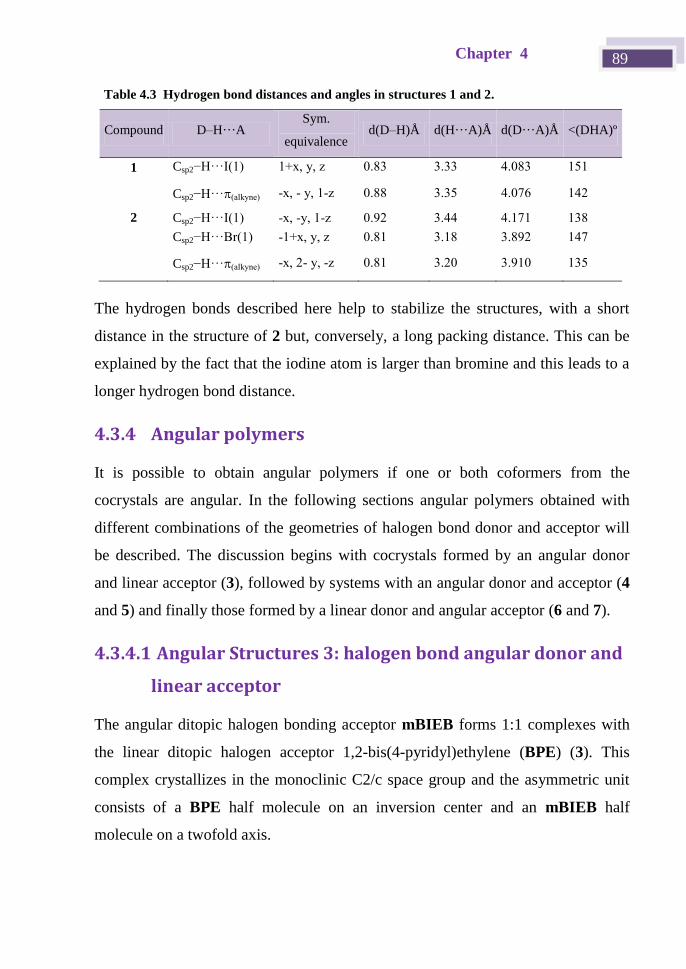
Chapter 4 89
The hydrogen bonds described here help to stabilize the structures, with a short
distance in the structure of 2 but, conversely, a long packing distance. This can be
explained by the fact that the iodine atom is larger than bromine and this leads to a
longer hydrogen bond distance.
4.3.4 Angular polymers
It is possible to obtain angular polymers if one or both coformers from the
cocrystals are angular. In the following sections angular polymers obtained with
different combinations of the geometries of halogen bond donor and acceptor will
be described. The discussion begins with cocrystals formed by an angular donor
and linear acceptor (3), followed by systems with an angular donor and acceptor (4
and 5) and finally those formed by a linear donor and angular acceptor (6 and 7).
4.3.4.1 Angular Structures 3: halogen bond angular donor and
linear acceptor
The angular ditopic halogen bonding acceptor mBIEB forms 1:1 complexes with
the linear ditopic halogen acceptor 1,2-bis(4-pyridyl)ethylene (BPE) (3). This
complex crystallizes in the monoclinic C2/c space group and the asymmetric unit
consists of a BPE half molecule on an inversion center and an mBIEB half
molecule on a twofold axis.
Table 4.3 Hydrogen bond distances and angles in structures 1 and 2.
Compound D–H···A Sym.
equivalence d(D–H)Å d(H···A)Å d(D···A)Å <(DHA)º
1 Csp2−H···I(1) 1+x, y, z 0.83 3.33 4.083 151
Csp2−H···(alkyne) -x, - y, 1-z 0.88 3.35 4.076 142
2 Csp2−H···I(1) -x, -y, 1-z 0.92 3.44 4.171 138
Csp2−H···Br(1) -1+x, y, z 0.81 3.18 3.892 147
Csp2−H···(alkyne) -x, 2- y, -z 0.81 3.20 3.910 135
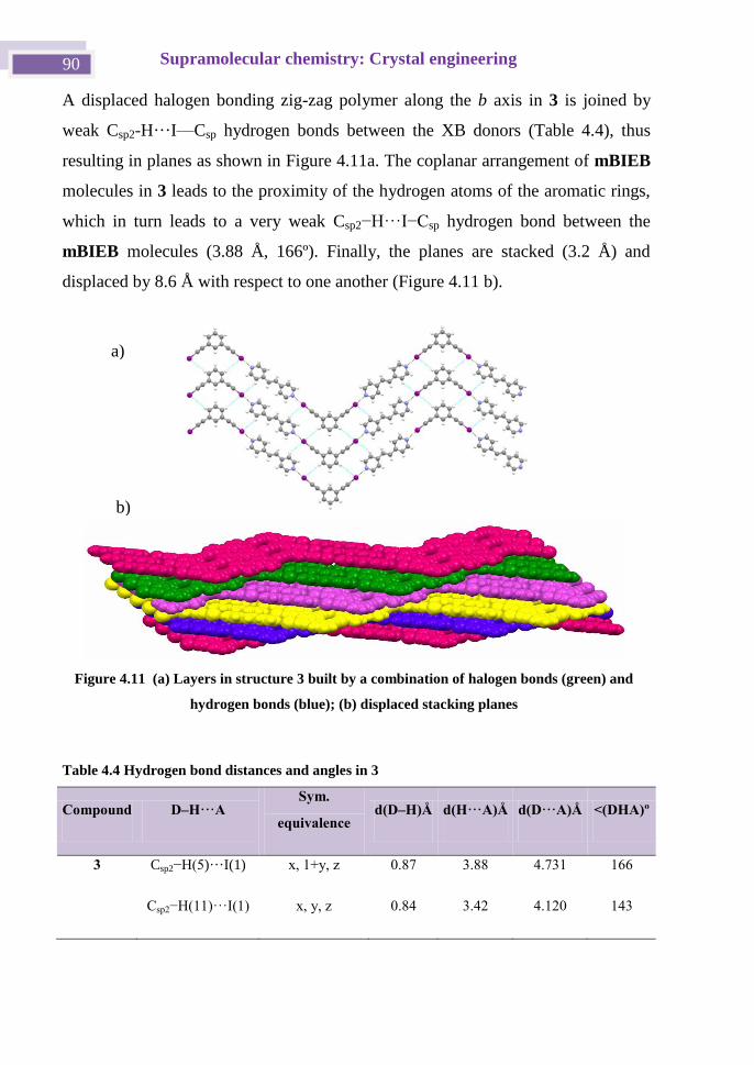
Supramolecular chemistry: Crystal engineering 90
A displaced halogen bonding zig-zag polymer along the b axis in 3 is joined by
weak Csp2-H···I—Csp hydrogen bonds between the XB donors (Table 4.4), thus
resulting in planes as shown in Figure 4.11a. The coplanar arrangement of mBIEB
molecules in 3 leads to the proximity of the hydrogen atoms of the aromatic rings,
which in turn leads to a very weak Csp2−H···I−Csp hydrogen bond between the
mBIEB molecules (3.88 Å, 166º). Finally, the planes are stacked (3.2 Å) and
displaced by 8.6 Å with respect to one another (Figure 4.11 b).
Table 4.4 Hydrogen bond distances and angles in 3
Compound D–H···A Sym.
equivalence d(D–H)Å d(H···A)Å d(D···A)Å <(DHA)º
3 Csp2−H( )···I(1) x, 1+y, z 0.87 3.88 4.731 166
Csp2−H(11)···I(1) x, y, z 0.84 3.42 4.120 143
Figure 4.11 (a) Layers in structure 3 built by a combination of halogen bonds (green) and
hydrogen bonds (blue); (b) displaced stacking planes
a)
b)
Chapter 4 91
4.3.4.2 Angular Structures 4, 5: Angular halogen bond donor and
acceptor.
Angular mBIEB forms 1:1 XB complexes with pyridazine and propanone and
these crystallize in the orthorhombic Pnma space group (4) and in the monoclinic
P21/n space group (5), respectively. The two asymmetric units consist of a half
molecule of mBIEB and half a molecule of the acceptor, i.e., pyrazine or
propanone.
The crystal structures 4 and 5 comprise zig-zag chains in which pyridazine (Figure
4.12a) and propanone act as ditopic halogen bond acceptors, in an analogous way
to that described for 4,4'-bis(dimethylamino)benzophenone and
dimethylformamide in halogen bonding cocrystal structures with 1,4-diiodo-
2,3,5,6-tetrafluorobenzene[32]
and di-iodoacetylene,[33]
respectively.
The halogen-bonded chains in 4 are dimerized by ··· stacking between
pyridazine and mBIEB rings that are tilted at an angle of 4.0º. The shortest
distance between rings is 3.38 Å and between centroids it is 3.50 Å. The parallel
dimerized chains are aligned along the c axis but these are shifted by 2.23 Å from
one another, which prevents ··· interactions. These alignments are arranged in a
parallel fashion as shown in Figure 4.12 b and this organization is criss-crossed
with a similar one at an angle of 53.3º to give rise to a 3D supramolecular network
(Figure 4.13 c). The structure is stabilized by a supramolecular synthon similar to
that described for structure 3 but this is not coplanar (Figure 4.12 d). This
arrangement allows a closer tie between the mBIEB molecules and, consequently,
the Csp2−H···I (3.79 Å, 133º) hydrogen bond is shorter than that in 3. The hydrogen
bond distances and angles in 4 and 5 are gathered in Table 4.5.
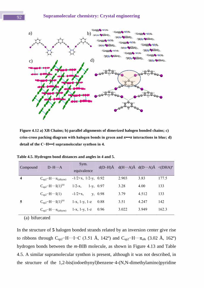
Supramolecular chemistry: Crystal engineering 92
Table 4.5. Hydrogen bond distances and angles in 4 and 5.
Compound D–H···A Sym.
equivalence d(D–H)Å d(H···A)Å d(D···A)Å <(DHA)º
4 Csp2−H···(alkyne) -1/2+x, 1/2-y,
1/2-z
0.92 2.903 3.83 177.5
Csp2−H···I(1)(a)
1/2-x, 1-y,
1/2-z
0.97 3.28 4.00 133
Csp2−H···I(1) -1/2+x, y,
1.5-z
0.98 3.79 4.512 133
5 Csp2−H···I(1)(a)
1-x, 1-y, 1-z 0.88 3.51 4.247 142
Csp2−H···(alkyne) 1-x, 1-y, 1-z 0.96 3.022 3.949 162.3
(a) bifurcated
In the structure of 5 halogen bonded strands related by an inversion center give rise
to ribbons through Csp2−H···I−C (3. 1 Å, 142º) and Csp2−H···πalk (3.02 Å, 162º)
hydrogen bonds between the m-BIB molecule, as shown in Figure 4.13 and Table
4.5. A similar supramolecular synthon is present, although it was not described, in
the structure of the 1,2-bis(iodoethynyl)benzene·4-(N,N-dimethylamino)pyridine
Figure 4.12 a) XB Chains; b) parallel alignments of dimerized halogen bonded chains; c)
criss-cross packing diagram with halogen bonds in green and π•••π interactions in blue; d)
detail of the C−H•••I supramolecular synthon in 4.
a) b)
c) d)
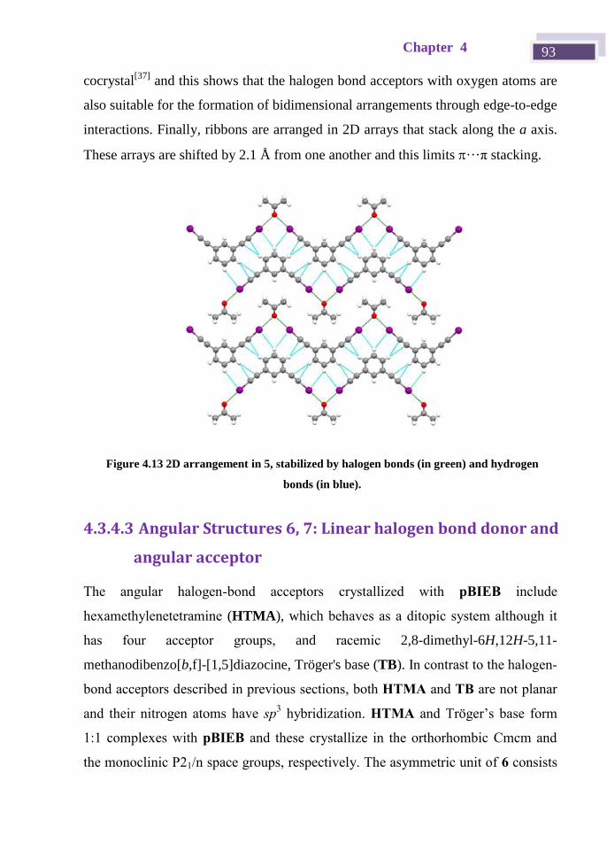
Chapter 4 93
cocrystal[37]
and this shows that the halogen bond acceptors with oxygen atoms are
also suitable for the formation of bidimensional arrangements through edge-to-edge
interactions. Finally, ribbons are arranged in 2D arrays that stack along the a axis.
These arrays are shifted by 2.1 Å from one another and this limits ···π stacking.
4.3.4.3 Angular Structures 6, 7: Linear halogen bond donor and
angular acceptor
The angular halogen-bond acceptors crystallized with pBIEB include
hexamethylenetetramine (HTMA), which behaves as a ditopic system although it
has four acceptor groups, and racemic 2,8-dimethyl-6H,12H-5,11-
methanodibenzo[b,f]-[1,5]diazocine, Tröger's base (TB). In contrast to the halogen-
bond acceptors described in previous sections, both HTMA and TB are not planar
and their nitrogen atoms have sp3 hybridization. HTMA and Tröger’s base form
1:1 complexes with pBIEB and these crystallize in the orthorhombic Cmcm and
the monoclinic P21/n space groups, respectively. The asymmetric unit of 6 consists
Figure 4.13 2D arrangement in 5, stabilized by halogen bonds (in green) and hydrogen
bonds (in blue).
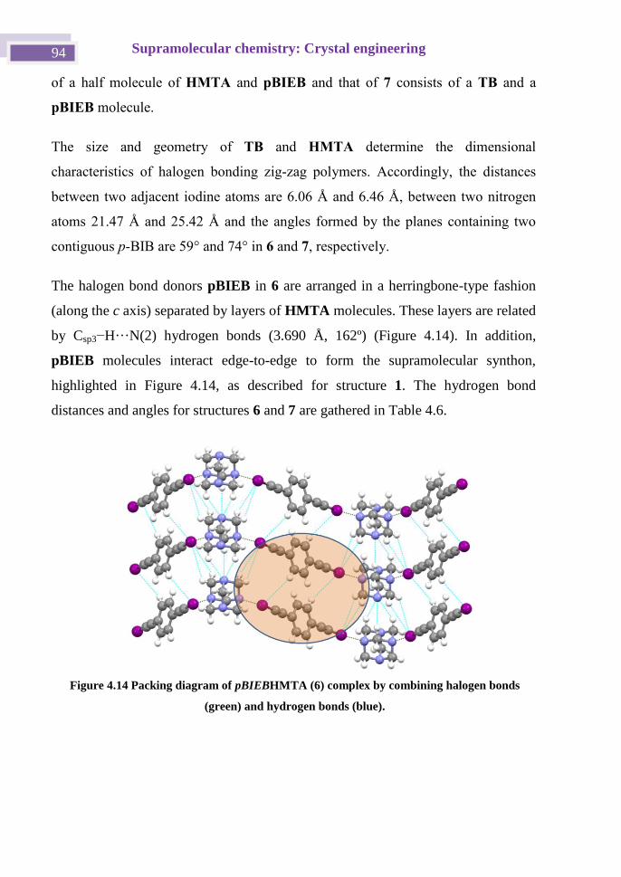
Supramolecular chemistry: Crystal engineering 94
of a half molecule of HMTA and pBIEB and that of 7 consists of a TB and a
pBIEB molecule.
The size and geometry of TB and HMTA determine the dimensional
characteristics of halogen bonding zig-zag polymers. Accordingly, the distances
between two adjacent iodine atoms are 6.06 Å and 6.46 Å, between two nitrogen
atoms 21.47 Å and 25.42 Å and the angles formed by the planes containing two
contiguous p-BIB are 59° and 74° in 6 and 7, respectively.
The halogen bond donors pBIEB in 6 are arranged in a herringbone-type fashion
(along the c axis) separated by layers of HMTA molecules. These layers are related
by Csp3−H···N(2) hydrogen bonds (3.690 Å, 162º) (Figure 4.14). In addition,
pBIEB molecules interact edge-to-edge to form the supramolecular synthon,
highlighted in Figure 4.14, as described for structure 1. The hydrogen bond
distances and angles for structures 6 and 7 are gathered in Table 4.6.
Figure 4.14 Packing diagram of pBIEBHMTA (6) complex by combining halogen bonds
(green) and hydrogen bonds (blue).
Chapter 4 95
Table 4.6. Hydrogen bonds in structures 6 and 7.
Compound D–H···A Sym.
equivalence d(D–H)Å d(H···A)Å d(D···A)Å <(DHA)°
6 Csp2−H···I(1) 1/2+x, 1/2+y, z 1.00 3.45 4.352 151
Csp2−H···N(2) 1.5-x, 1/2+y,
1/2-z
1.07 3.04 3.968 146
Csp2−H···N(2) 1.5-x,1/2+y,
1/2-z
1.08 2.64 3.69 162
Csp2−H···I(1) 1+x, y, z 1.07 3.48 3.911 111
7 Csp2−H···π(alkyne) x, y, z 0.970 2.730 3.668 162.6
Csp2−H···(arene) 1-x, 1-y, 1-z 0.970 2.780 3.747 174.9
Csp2−H···(arene) x, y, z 0.97(6) 2.699 3.665 171.9
Csp2−H···I(1) -1+x, y, -1+z 0.970 3.405 4.230 142.2
Csp2−H···I(1) -1+x, y, z 0.961 3.123 3.964 147.1
Csp2−H···I(2) 1/2+x, 1/2-y,
1/2+z
0.930 3.351 4.124 142.0
TB core 1,5-diazabicyclo[1.3.3]nonane and the two attached aryl groups produce a
rigid V-shaped molecule with a cleft angle of ca. 99° and an inherent chiral C2-
symmetry. The high framework stability, along with the relative ease of preparation
and derivatization, offers an attractive starting point for a variety of functional
materials.[36, 38]
[39]
Despite this potential, only two TB cocrystal structures have
been described to date and these were based on (−)-dibenzoyl-L-tartaric acid[40]
and
TB.[41]
In the structure of 7 the strength and directionality of XB translates the exo-face to
exo-face TB dimers (Figure 4.15 (a)) stabilized by weak Csp3−H···π(arene) hydrogen
bonds (2.78 Å and 175º) into 2D layers. These layers are built by rhombic units
with a side length of 14 Å (Figure 4.15 (b)).
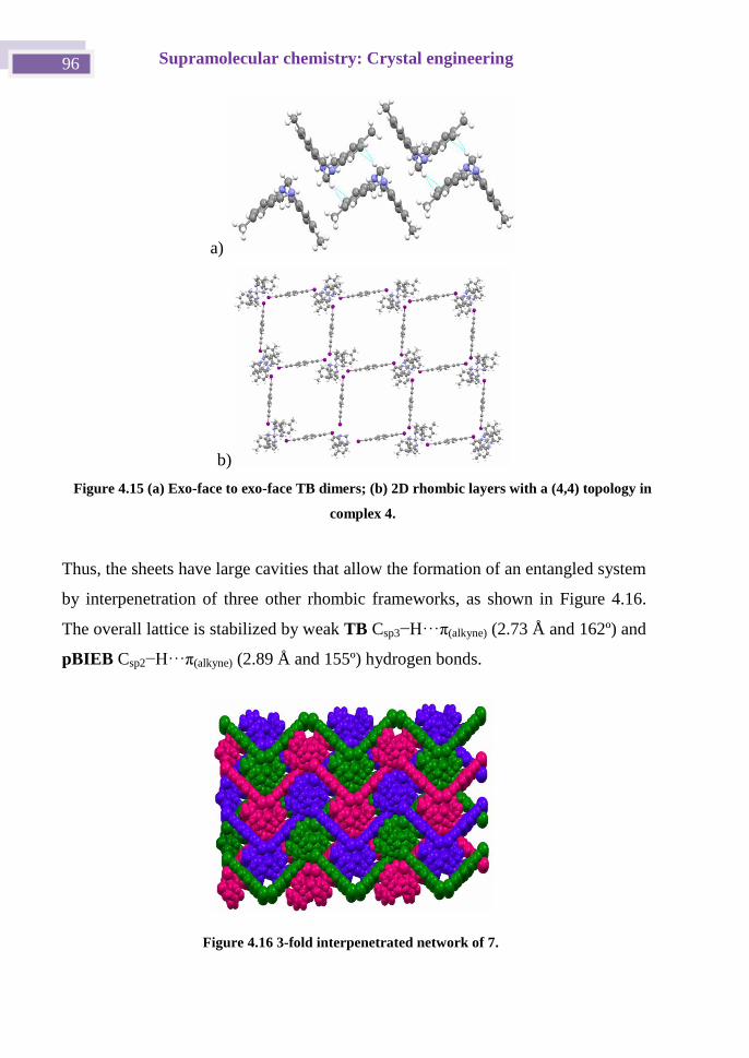
Supramolecular chemistry: Crystal engineering 96
Thus, the sheets have large cavities that allow the formation of an entangled system
by interpenetration of three other rhombic frameworks, as shown in Figure 4.16.
The overall lattice is stabilized by weak TB Csp3−H···π(alkyne) (2.73 Å and 162º) and
pBIEB Csp2−H···π(alkyne) (2.89 Å and 155º) hydrogen bonds.
Figure 4.16 3-fold interpenetrated network of 7.
a)
b)
Figure 4.15 (a) Exo-face to exo-face TB dimers; (b) 2D rhombic layers with a (4,4) topology in
complex 4.
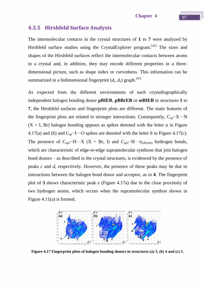
Chapter 4 97
4.3.5 Hirshfeld Surface Analysis
The intermolecular contacts in the crystal structures of 1 to 7 were analyzed by
Hirshfeld surface studies using the CrystalExplorer program.[42]
The sizes and
shapes of the Hirshfeld surfaces reflect the intermolecular contacts between atoms
in a crystal and, in addition, they may encode different properties in a three-
dimensional picture, such as shape index or curvedness. This information can be
summarized in a bidimensional fingerprint (di, de) graph.[43]
As expected from the different environments of each crystallographically
independent halogen bonding donor pBIEB, pBBrEB or mBIEB in structures 1 to
7, the Hirshfeld surfaces and fingerprint plots are different. The main features of
the fingerprint plots are related to stronger interactions. Consequently, Csp−X···N
(X = I, Br) halogen bonding appears as spikes denoted with the letter a in Figure
4.17(a) and (b) and Csp−I···O spikes are denoted with the letter b in Figure 4.17(c).
The presence of Csp2−H···X (X = Br, I) and Csp2−H···(alkyne) hydrogen bonds,
which are characteristic of edge-to-edge supramolecular synthons that join halogen
bond donors – as described in the crystal structures, is evidenced by the presence of
peaks c and d, respectively. However, the presence of these peaks may be due to
interactions between the halogen bond donor and acceptor, as in 4. The fingerprint
plot of 3 shows characteristic peak e (Figure 4.17a) due to the close proximity of
two hydrogen atoms, which occurs when the supramolecular synthon shown in
Figure 4.11(a) is formed.
Figure 4.17 Fingerprint plots of halogen bonding donors in structures (a) 3, (b) 4 and (c) 5.
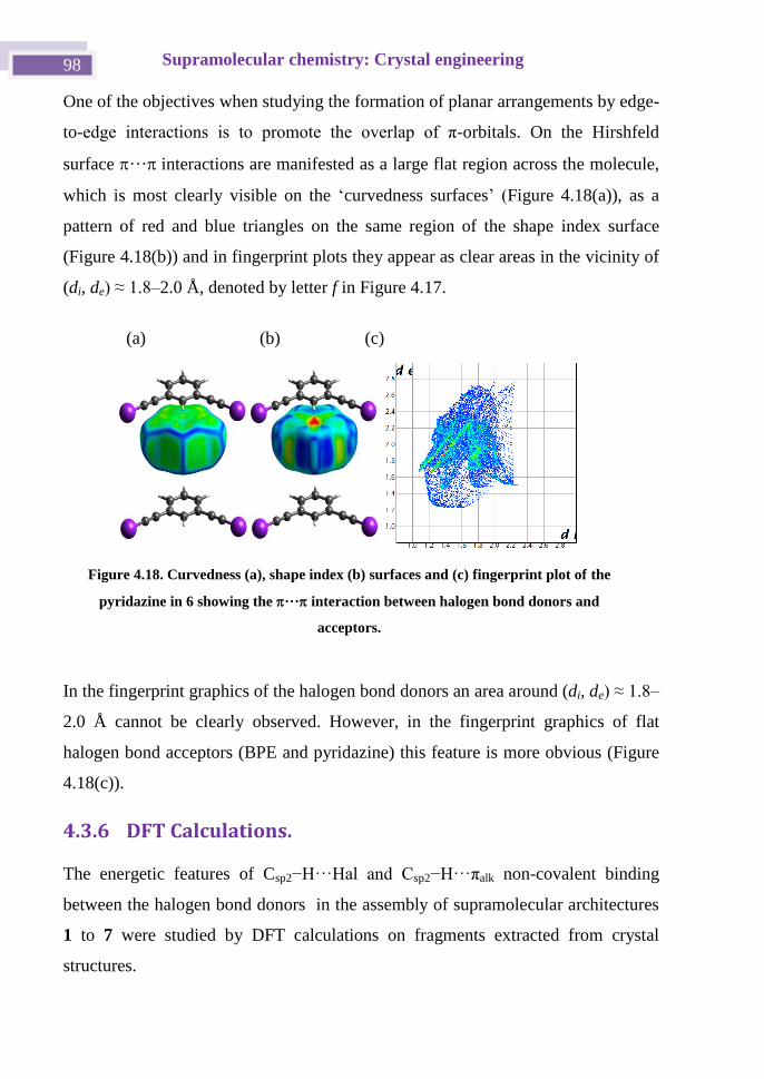
Supramolecular chemistry: Crystal engineering 98
One of the objectives when studying the formation of planar arrangements by edge-
to-edge interactions is to promote the overlap of π-orbitals. On the Hirshfeld
surface ···interactions are manifested as a large flat region across the molecule,
which is most clearly visible on the ‘curvedness surfaces’ (Figure 4.18(a)), as a
pattern of red and blue triangles on the same region of the shape index surface
(Figure 4.18(b)) and in fingerprint plots they appear as clear areas in the vicinity of
(di, de) ≈ 1.8–2.0 Å, denoted by letter f in Figure 4.17.
In the fingerprint graphics of the halogen bond donors an area around (di, de) ≈ 1.8–
2.0 Å cannot be clearly observed. However, in the fingerprint graphics of flat
halogen bond acceptors (BPE and pyridazine) this feature is more obvious (Figure
4.18(c)).
4.3.6 DFT Calculations.
The energetic features of Csp2−H···Hal and Csp2−H···πalk non-covalent binding
between the halogen bond donors in the assembly of supramolecular architectures
1 to 7 were studied by DFT calculations on fragments extracted from crystal
structures.
(a) (b) (c)
Figure 4.18. Curvedness (a), shape index (b) surfaces and (c) fingerprint plot of the
pyridazine in 6 showing the ··· interaction between halogen bond donors and
acceptors.
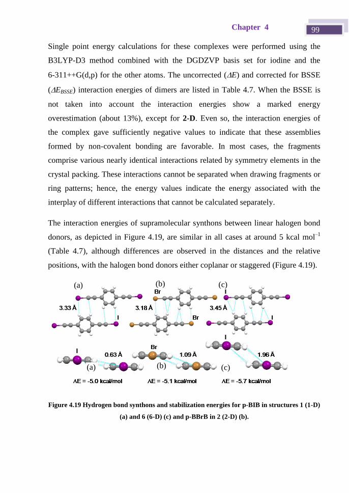
Chapter 4 99
Single point energy calculations for these complexes were performed using the
B3LYP-D3 method combined with the DGDZVP basis set for iodine and the
6-311++G(d,p) for the other atoms. The uncorrected (E) and corrected for BSSE
(EBSSE) interaction energies of dimers are listed in Table 4.7. When the BSSE is
not taken into account the interaction energies show a marked energy
overestimation (about 13%), except for 2-D. Even so, the interaction energies of
the complex gave sufficiently negative values to indicate that these assemblies
formed by non-covalent bonding are favorable. In most cases, the fragments
comprise various nearly identical interactions related by symmetry elements in the
crystal packing. These interactions cannot be separated when drawing fragments or
ring patterns; hence, the energy values indicate the energy associated with the
interplay of different interactions that cannot be calculated separately.
The interaction energies of supramolecular synthons between linear halogen bond
donors, as depicted in Figure 4.19, are similar in all cases at around 5 kcal mol–1
(Table 4.7), although differences are observed in the distances and the relative
positions, with the halogen bond donors either coplanar or staggered (Figure 4.19).
Figure 4.19 Hydrogen bond synthons and stabilization energies for p-BIB in structures 1 (1-D)
(a) and 6 (6-D) (c) and p-BBrB in 2 (2-D) (b).
(a) (b) (c)
(c) (a) (b)

Supramolecular chemistry: Crystal engineering 100
Table 4.7 Uncorrected and corrected interaction energies of dimers (ΔE and ΔEBSSE,
respectively, kcal mol–1
) calculated using B3LYP-D3/6-311++(d,p)-DGDZVP (single point
calculations).
Dimers(a)
ΔE kcal mol
–1 ΔEBSSE kcal mol–1
1-D –5.7 –5.0
2-D –5.1 –5.1
3-D –3.4 –2.9
4-D –4.1 –3.5
5-D –5.5 –4.8
6-D –6.5 –5.7
(a) D = Dimersupramolecular synthon)in structures 1 to 6, see Figure 4.19 and Figure 4.20
In compounds 3, 4 and 5, mBIEB forms three types of supramolecular synthon.
These are shown in Figure 4.20, with two formed only by two Csp2−H··I hydrogen
bonds with a stabilization energy of about 3 kcal mol–1
, and the other formed by
two Csp2−H··I and two Csp2−H···(alkyne) hydrogen bonds with a stabilization energy
of 4.8 kcal mol–1
. Despite the weak energies, it has been demonstrated that the
effects of these interactions on the crystal structure and packing are relevant.
Figure 4.20 Supramolecular synthons and stabilization energies for m-BIB in structures 3 (3-
D) (a), 4 (4-D) (b) and 5 (5-D) (c).
With the aim of supporting our hypothesis, different intermolecular contacts in the
arrays were systematically investigated beyond the sum of the van der Waals radii,
(a) (b) (c)
Chapter 4 101
since it has been noted that the use of the sum of van der Waals radii as a cut-off
parameter to assess and evaluate weak C−H···X hydrogen bonds is not
recommended and should not be taken into account.[26]
To date, more attention has been paid to the halogen-bonding donor character of
haloethynylbenzene derivatives. Thus, pBIEB, pBBrEB and mBIEB are strong
ditopic XB donors that form linear or angular polymers with ditopic linear or
angular halogen bond acceptors such as BPE, pyridazine, propanone, HTMA and
Tröger's base.
As we proposed, the complementarity of the bis(haloethynyl)benzene derivatives
by Csp2−H···X and Csp2−H···(alkyne) edge-to-edge hydrogen bonds that favor the
formation of planar supramolecular synthons has been demonstrated. It was
determined by means of DFT calculations that the negative interaction energies of
such supramolecular synthons range from 2.9 to 5.7 kcal mol–1
. In spite of these
weak energies, their effects on the crystal structure and packing are relevant and, in
combination with strong halogen bonds, these interactions have proven to represent
a useful strategy for the formation of two-dimensional arrangements in cocrystals
with nitrogen and oxygen XB acceptors. Such materials are of great interest in the
development of molecular organic materials.
Supramolecular chemistry: Crystal engineering 102
4.4 Halogen bonding salts
As mentioned in the introduction of this chapter, this second section is devoted to
the study of halogen bonding salts formed by pBIEB linear, rigid and ditopic
halogen bond donors with four bromide salts of di(iodioethynyl)benzene
derivatives to coordinate bromide anions as a function of the size and geometry of
the countercations and how they influence the supramolecular architectures
obtained. In addition, we established the thermodynamic features of the halogen
bond interactions of such salts in solution by isothermal titration calorimetry (ITC).
4.4.1 Previous works
The study of the complexation of anions has moved from being an area of
academic interest to a fundamental pillar of supramolecular chemistry with
applications in many areas.[3f]
In recent years a large number of anion sensors,[3f]
anion-responsive materials, and organo catalytic processes involving anion
complexation have been developed.[44]
Anions, such as transition metals, have a
primary valence, i.e., a negative charge, and a secondary valence, i.e., the number
of ligands that surround the anions and form their coordination sphere. This
valence largely exceeds the requirements of the neutrality principle both in the
solid state and in solution. The types of non-covalent interactions typically used to
bind anionic guests include electrostatic interactions, coordination to metal ions,
hydrogen bonding (HB) and, more recently, halogen bonding (XB).
Halogen bonding was shown to provide a highly efficient and directional
interaction towards anion coordination.[45]
Anions, and particularly the smallest
halide ones, act as very good halogen bond acceptors as their negative charge is
concentrated on one single atom. Halide anions – like halogen bond acceptors –
can adopt a variety of coordination numbers due to their spherical nature, with up
to eight halogen bonds. Nevertheless, it has been shown that the halides have a
moderate bias towards the formation of two or three X-bonds.[45e]
On the basis of
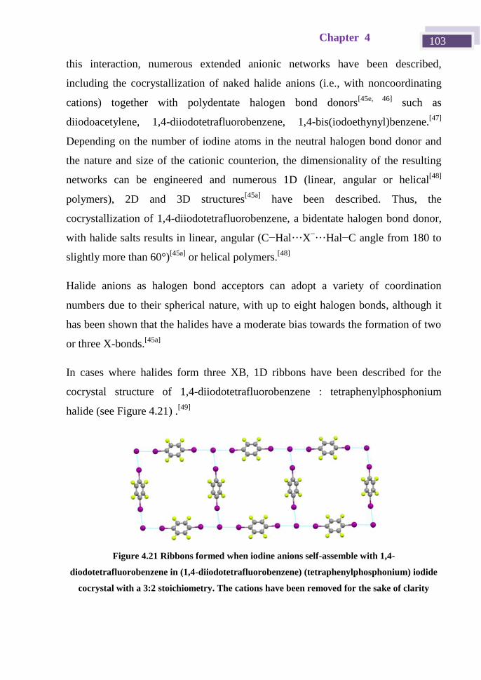
Chapter 4 103
this interaction, numerous extended anionic networks have been described,
including the cocrystallization of naked halide anions (i.e., with noncoordinating
cations) together with polydentate halogen bond donors[45e, 46]
such as
diiodoacetylene, 1,4-diiodotetrafluorobenzene, 1,4-bis(iodoethynyl)benzene.[47]
Depending on the number of iodine atoms in the neutral halogen bond donor and
the nature and size of the cationic counterion, the dimensionality of the resulting
networks can be engineered and numerous 1D (linear, angular or helical[48]
polymers), 2D and 3D structures[45a]
have been described. Thus, the
cocrystallization of 1,4-diiodotetrafluorobenzene, a bidentate halogen bond donor,
with halide salts results in linear, angular (C−Hal···X−···Hal−C angle from 180 to
slightly more than 60°)[45a]
or helical polymers.[48]
Halide anions as halogen bond acceptors can adopt a variety of coordination
numbers due to their spherical nature, with up to eight halogen bonds, although it
has been shown that the halides have a moderate bias towards the formation of two
or three X-bonds.[45a]
In cases where halides form three XB, 1D ribbons have been described for the
cocrystal structure of 1,4-diiodotetrafluorobenzene : tetraphenylphosphonium
halide (see Figure 4.21) .[49]
Figure 4.21 Ribbons formed when iodine anions self-assemble with 1,4-
diodotetrafluorobenzene in (1,4-diiodotetrafluorobenzene) (tetraphenylphosphonium) iodide
cocrystal with a 3:2 stoichiometry. The cations have been removed for the sake of clarity
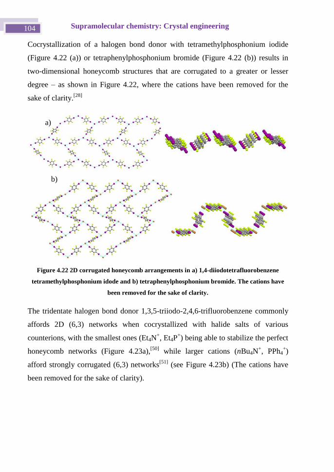
Supramolecular chemistry: Crystal engineering 104
Cocrystallization of a halogen bond donor with tetramethylphosphonium iodide
(Figure 4.22 (a)) or tetraphenylphosphonium bromide (Figure 4.22 (b)) results in
two-dimensional honeycomb structures that are corrugated to a greater or lesser
degree – as shown in Figure 4.22, where the cations have been removed for the
sake of clarity.[28]
Figure 4.22 2D corrugated honeycomb arrangements in a) 1,4-diiodotetrafluorobenzene
tetramethylphosphonium idode and b) tetraphenylphosphonium bromide. The cations have
been removed for the sake of clarity.
The tridentate halogen bond donor 1,3,5-triiodo-2,4,6-trifluorobenzene commonly
affords 2D (6,3) networks when cocrystallized with halide salts of various
counterions, with the smallest ones (Et4N+, Et4P
+) being able to stabilize the perfect
honeycomb networks (Figure 4.23a),[50]
while larger cations (nBu4N+, PPh4
+)
afford strongly corrugated (6,3) networks[51]
(see Figure 4.23b) (The cations have
been removed for the sake of clarity).
a)
b)
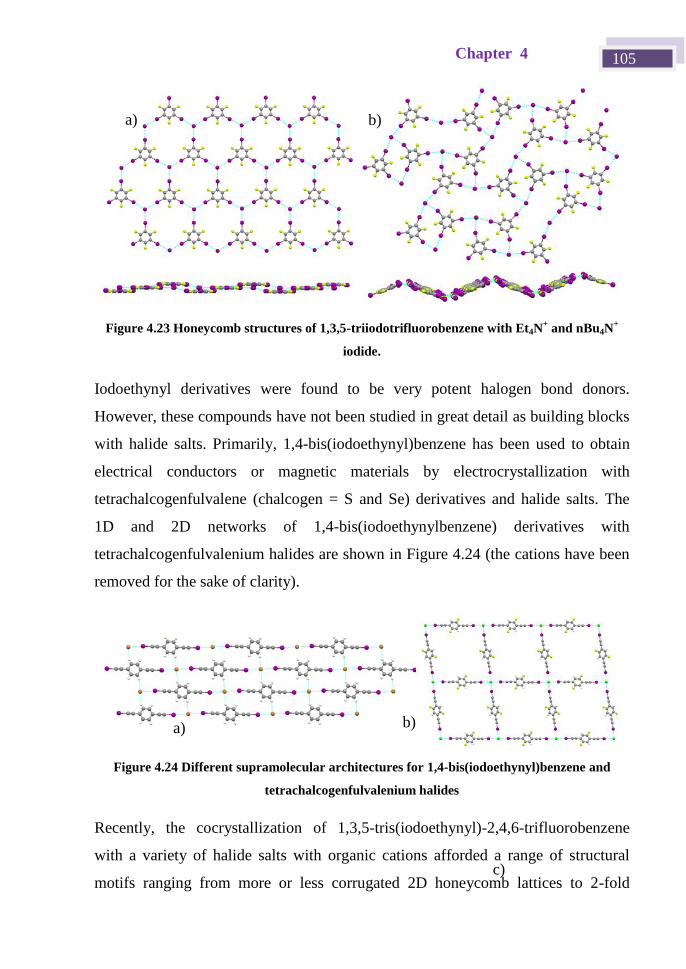
Chapter 4 105
Figure 4.23 Honeycomb structures of 1,3,5-triiodotrifluorobenzene with Et4N+ and nBu4N
+
iodide.
Iodoethynyl derivatives were found to be very potent halogen bond donors.
However, these compounds have not been studied in great detail as building blocks
with halide salts. Primarily, 1,4-bis(iodoethynyl)benzene has been used to obtain
electrical conductors or magnetic materials by electrocrystallization with
tetrachalcogenfulvalene (chalcogen = S and Se) derivatives and halide salts. The
1D and 2D networks of 1,4-bis(iodoethynylbenzene) derivatives with
tetrachalcogenfulvalenium halides are shown in Figure 4.24 (the cations have been
removed for the sake of clarity).
Figure 4.24 Different supramolecular architectures for 1,4-bis(iodoethynyl)benzene and
tetrachalcogenfulvalenium halides
Recently, the cocrystallization of 1,3,5-tris(iodoethynyl)-2,4,6-trifluorobenzene
with a variety of halide salts with organic cations afforded a range of structural
motifs ranging from more or less corrugated 2D honeycomb lattices to 2-fold
a) b)
a) b)
c)
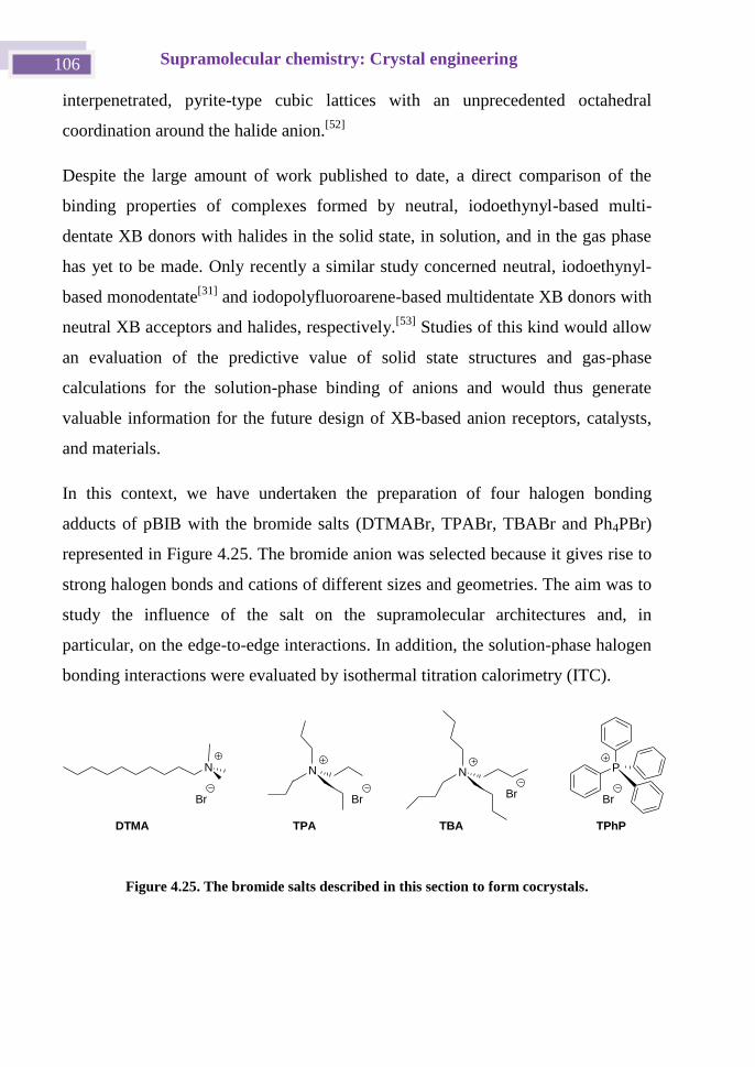
Supramolecular chemistry: Crystal engineering 106
interpenetrated, pyrite-type cubic lattices with an unprecedented octahedral
coordination around the halide anion.[52]
Despite the large amount of work published to date, a direct comparison of the
binding properties of complexes formed by neutral, iodoethynyl-based multi-
dentate XB donors with halides in the solid state, in solution, and in the gas phase
has yet to be made. Only recently a similar study concerned neutral, iodoethynyl-
based monodentate[31]
and iodopolyfluoroarene-based multidentate XB donors with
neutral XB acceptors and halides, respectively.[53]
Studies of this kind would allow
an evaluation of the predictive value of solid state structures and gas-phase
calculations for the solution-phase binding of anions and would thus generate
valuable information for the future design of XB-based anion receptors, catalysts,
and materials.
In this context, we have undertaken the preparation of four halogen bonding
adducts of pBIB with the bromide salts (DTMABr, TPABr, TBABr and Ph4PBr)
represented in Figure 4.25. The bromide anion was selected because it gives rise to
strong halogen bonds and cations of different sizes and geometries. The aim was to
study the influence of the salt on the supramolecular architectures and, in
particular, on the edge-to-edge interactions. In addition, the solution-phase halogen
bonding interactions were evaluated by isothermal titration calorimetry (ITC).
Br
PN N N
BrBr
Br
TPA TBA TPhPDTMA
Figure 4.25. The bromide salts described in this section to form cocrystals.
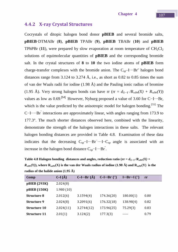
Chapter 4 107
4.4.2 X-ray Crystal Structures
Cocrystals of ditopic halogen bond donor pBIEB and several bromide salts,
pBIEB·DTMABr (8), pBIEB TPABr (9), pBIEB TBABr (10) and pBIEB
TPhPBr (11), were prepared by slow evaporation at room temperature of CH2Cl2
solutions of equimolecular quantities of pBIEB and the corresponding bromide
salt. In the crystal structures of 8 to 10 the two iodine atoms of pBIEB form
charge-transfer complexes with the bromide anion. The Csp–I···Br‾ halogen bond
distances range from 3.124 to 3.274 Å, i.e., as short as 0.82 to 0.85 times the sum
of van der Waals radii for iodine (1.98 Å) and the Pauling ionic radius of bromine
(1.95 Å). Very strong halogen bonds can have rr (rr = dX···Y /RvdW(X) + RvdW(Y))
values as low as 0.69.[54]
However, Nyburg proposed a value of 3.60 for C−I···Br,
which is the value predicted by the anisotropic model for halogen bonding.[55]
The
C−I····Br‾ interactions are approximately linear, with angles ranging from 173.9 to
177.3°. The much shorter distances observed here, combined with the linearity,
demonstrate the strength of the halogen interactions in these salts. The relevant
halogen bonding distances are provided in Table 4.8. Examination of these data
indicates that the decreasing Csp−I···Br−···I−Csp angle is associated with an
increase in the halogen bond distance Csp−I···Br‾.
Table 4.8 Halogen bonding distances and angles, reduction ratio (rr = dX···Y /RvdW(X) +
RvdW(Y)), where RwdW(X) is the van der Waals radius of iodine (1.98 Å) and RwdW(Y) is the
radius of the halide anion (1.95 Å)
Comp C–I (Å) C–I···Br- (Å) C–I···Br- (°) I···Br···I (°) rr
pBIEB (293K) 2.024(8)
pBIEB (150K) 1.980 (10)
Structure 8 2.012(6) 3.1594(4) 174.36(20) 180.00(1) 0.80
Structure 9 2.024(8) 3.2091(6) 176.32(18) 138.98(4) 0.82
Structure 10 2.024(11) 3.2744(12) 173.96(25) 75.29(3) 0.83
Structure 11 2.01(1) 3.124(2) 177.3(3) ----- 0.79
Supramolecular chemistry: Crystal engineering 108
Analysis of the four structures from the point of view of the halide anion provides a
striking ‘coordination’ around the Br‾ anion. The heteromeric three-component
systems 8 to 10 are characterized by the presence of infinite, one-dimensional, X-
bonded chains in which the pBIEB and the halide anions alternate and behave as
ditopic XB donors and acceptors, respectively. The I···Br‾···I angles range from
straight in structure 8 to the acute angle 75.29° in structure 10. Structure 9 shows
an intermediate angle (138º). The coordination spheres of bromide anions and
iodine atoms are completed by hydrogen bonds.
In the following sections we will describe each structure and compare the
differences between them due to cation size and shape.
4.4.2.1 pBIEB•DTMABr complex, structure 8.
Halogen bonded pBIEB·DTMABr in a 1:1 complex crystallizes in the monoclinic
space group P21/m, where the asymmetric unit consists of a pBIEB half molecule
located at an inversion center, one half DTMA on a mirror plane perpendicular to
[0 1 0] and half a Br‾ anion at an inversion center.
The bromide anion forms two halogen bonds (C−I···Br‾ 3.1 Å and 1 4.3º) with
pBIEB and two hydrogen bonds (C−H···Br‾ 2.813 Å and 1 3.0 º) from the cation.
The bromide coordination sphere is distorted square planar (I···Br‾···I and
H···Br‾···H 180º, I···Br‾···H 81.8º and 8.2º), leading to a three-dimensional
supramolecular structure (Figure 4.26). The cation is also joined to the polymeric
chain by a hydrogen bond to the iodine (C−H···I−C 3.11 Å and .3º).
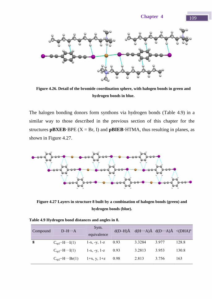
Chapter 4 109
The halogen bonding donors form synthons via hydrogen bonds (Table 4.9) in a
similar way to those described in the previous section of this chapter for the
structures pBXEB·BPE (X = Br, I) and pBIEB·HTMA, thus resulting in planes, as
shown in Figure 4.27.
Figure 4.27 Layers in structure 8 built by a combination of halogen bonds (green) and
hydrogen bonds (blue).
Table 4.9 Hydrogen bond distances and angles in 8.
Compound D–H···A Sym.
equivalence d(D–H)Å d(H···A)Å d(D···A)Å <(DHA)º
8 Csp2−H···(1) 1-x, -y, 1-z 0.93 3.3284 3.977 128.8
Csp2−H···I(1) 1-x, -y, 1-z 0.93 3.2813 3.953 130.8
Csp2−H···Br(1) 1+x, y, 1+z 0.98 2.813 3.756 163
Figure 4.26. Detail of the bromide coordination sphere, with halogen bonds in green and
hydrogen bonds in blue.

Supramolecular chemistry: Crystal engineering 110
The linear infinite chains formed by Br‾···pBIEB···Br‾ halogen bonds are
arranged in almost perpendicular planes with respect to the b axis (Figure 4.28).
Figure 4.28 Projection of pBIEB·DTMABr showing the layered nature of the anionic and
cationic networks.
This organization can be facilitated by the similarity in the length of the
decyltrimethylammonium cation (15.48 Å) and the bromide pBIEB assembly
(15.22 Å) (Figure 4.29). This situation is similar to that described previously by
Yamamoto and Kato for structures of pBIEB and their derivatives with halogen
anions and tetrathiafulvalene cations and by Metrangolo et al. in structures of -
diiodoperfluoroalkane with bis(trimethylammonium)alkane diiodides.[56]
Figure 4.29 Comparison between the length of the DTMA cation and pBIEB···Br‾ anionic
assembly
15.479 Å
15.220 Å
15.479 Å
15.220 Å
15.479 Å
15.220 Å
15.479 Å
15.220 Å
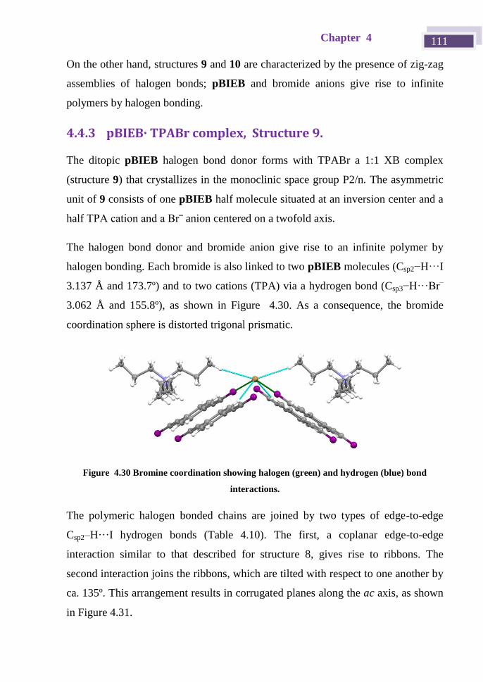
Chapter 4 111
On the other hand, structures 9 and 10 are characterized by the presence of zig-zag
assemblies of halogen bonds; pBIEB and bromide anions give rise to infinite
polymers by halogen bonding.
4.4.3 pBIEB· TPABr complex, Structure 9.
The ditopic pBIEB halogen bond donor forms with TPABr a 1:1 XB complex
(structure 9) that crystallizes in the monoclinic space group P2/n. The asymmetric
unit of 9 consists of one pBIEB half molecule situated at an inversion center and a
half TPA cation and a Br‾ anion centered on a twofold axis.
The halogen bond donor and bromide anion give rise to an infinite polymer by
halogen bonding. Each bromide is also linked to two pBIEB molecules (Csp2−H···I
3.137 Å and 173.7º) and to two cations (TPA) via a hydrogen bond (Csp3−H···Br–
3.062 Å and 155.8º), as shown in Figure 4.30. As a consequence, the bromide
coordination sphere is distorted trigonal prismatic.
Figure 4.30 Bromine coordination showing halogen (green) and hydrogen (blue) bond
interactions.
The polymeric halogen bonded chains are joined by two types of edge-to-edge
Csp2–H···I hydrogen bonds (Table 4.10). The first, a coplanar edge-to-edge
interaction similar to that described for structure 8, gives rise to ribbons. The
second interaction joins the ribbons, which are tilted with respect to one another by
ca. 135º. This arrangement results in corrugated planes along the ac axis, as shown
in Figure 4.31.
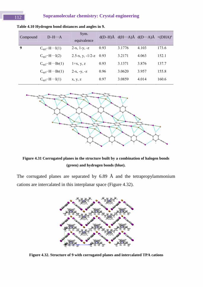
Supramolecular chemistry: Crystal engineering 112
Table 4.10 Hydrogen bond distances and angles in 9.
Compound D–H···A Sym.
equivalence d(D–H)Å d(H···A)Å d(D···A)Å <(DHA)º
9 Csp2−H···(1) 2-x, 1-y, -z 0.93 3.1776 4.103 173.6
Csp2−H···I(2) 2.5-x, y, -1/2-z 0.93 3.2171 4.063 152.1
Csp2−H···Br(1) 1+x, y, z 0.93 3.1371 3.876 137.7
Csp3−H···Br(1) 2-x, -y, -z 0.96 3.0620 3.957 155.8
Csp3−H···I(1) x, y, z 0.97 3.0859 4.014 160.6
Figure 4.31 Corrugated planes in the structure built by a combination of halogen bonds
(green) and hydrogen bonds (blue).
The corrugated planes are separated by 6.89 Å and the tetrapropylammonium
cations are intercalated in this interplanar space (Figure 4.32).
Figure 4.32. Structure of 9 with corrugated planes and intercalated TPA cations
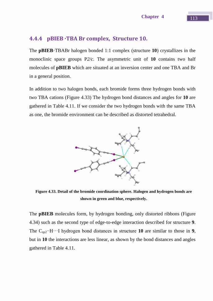
Chapter 4 113
4.4.4 pBIEB ·TBA Br complex, Structure 10.
The pBIEB·TBABr halogen bonded 1:1 complex (structure 10) crystallizes in the
monoclinic space groups P2/c. The asymmetric unit of 10 contains two half
molecules of pBIEB which are situated at an inversion center and one TBA and Br
in a general position.
In addition to two halogen bonds, each bromide forms three hydrogen bonds with
two TBA cations (Figure 4.33) The hydrogen bond distances and angles for 10 are
gathered in Table 4.11. If we consider the two hydrogen bonds with the same TBA
as one, the bromide environment can be described as distorted tetrahedral.
The pBIEB molecules form, by hydrogen bonding, only distorted ribbons (Figure
4.34) such as the second type of edge-to-edge interaction described for structure 9.
The Csp2−H···I hydrogen bond distances in structure 10 are similar to those in 9,
but in 10 the interactions are less linear, as shown by the bond distances and angles
gathered in Table 4.11.
Figure 4.33. Detail of the bromide coordination sphere. Halogen and hydrogen bonds are
shown in green and blue, respectively.
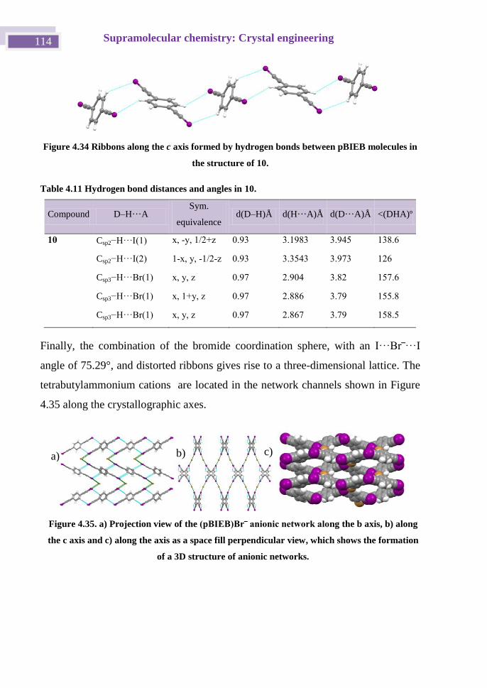
Supramolecular chemistry: Crystal engineering 114
Figure 4.34 Ribbons along the c axis formed by hydrogen bonds between pBIEB molecules in
the structure of 10.
Table 4.11 Hydrogen bond distances and angles in 10.
Compound D–H···A Sym.
equivalence d(D–H)Å d(H···A)Å d(D···A)Å <(DHA)º
10 Csp2−H···(1) x, -y, 1/2+z 0.93 3.1983 3.945 138.6
Csp2−H···I(2) 1-x, y, -1/2-z 0.93 3.3543 3.973 126
Csp3−H···Br(1) x, y, z 0.97 2.904 3.82 157.6
Csp3−H···Br(1) x, 1+y, z 0.97 2.886 3.79 155.8
Csp3−H···Br(1) x, y, z 0.97 2.867 3.79 158.5
Finally, the combination of the bromide coordination sphere, with an I···Br‾···I
angle of 75.29°, and distorted ribbons gives rise to a three-dimensional lattice. The
tetrabutylammonium cations are located in the network channels shown in Figure
4.35 along the crystallographic axes.
Figure 4.35. a) Projection view of the (pBIEB)Br‾ anionic network along the b axis, b) along
the c axis and c) along the axis as a space fill perpendicular view, which shows the formation
of a 3D structure of anionic networks.
a) b) c)
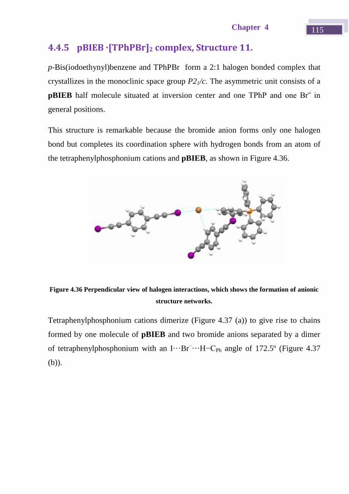
Chapter 4 115
4.4.5 pBIEB ·[TPhPBr]2 complex, Structure 11.
p-Bis(iodoethynyl)benzene and TPhPBr form a 2:1 halogen bonded complex that
crystallizes in the monoclinic space group P21/c. The asymmetric unit consists of a
pBIEB half molecule situated at inversion center and one TPhP and one Br‾ in
general positions.
This structure is remarkable because the bromide anion forms only one halogen
bond but completes its coordination sphere with hydrogen bonds from an atom of
the tetraphenylphosphonium cations and pBIEB, as shown in Figure 4.36.
Figure 4.36 Perpendicular view of halogen interactions, which shows the formation of anionic
structure networks.
Tetraphenylphosphonium cations dimerize (Figure 4.37 (a)) to give rise to chains
formed by one molecule of pBIEB and two bromide anions separated by a dimer
of tetraphenylphosphonium with an I···Br–···H−CPh angle of 172.5º (Figure 4.37
(b)).
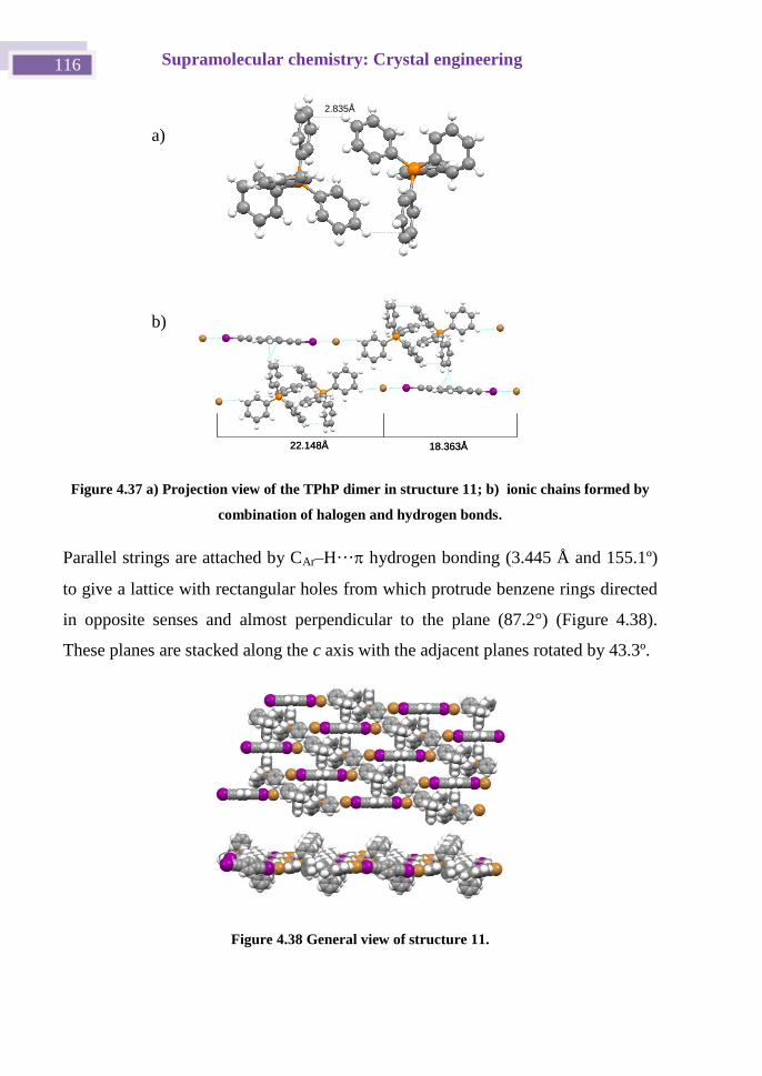
Supramolecular chemistry: Crystal engineering 116
Figure 4.37 a) Projection view of the TPhP dimer in structure 11; b) ionic chains formed by
combination of halogen and hydrogen bonds.
Parallel strings are attached by CAr–H··· hydrogen bonding (3.445 Å and 155.1º)
to give a lattice with rectangular holes from which protrude benzene rings directed
in opposite senses and almost perpendicular to the plane (87.2°) (Figure 4.38).
These planes are stacked along the c axis with the adjacent planes rotated by 43.3º.
Figure 4.38 General view of structure 11.
2.835Å
18.363Å22.148Å 18.363Å22.148Å
2.835Å
18.363Å22.148Å 18.363Å22.148Å
a)
b)
Chapter 4 117
4.4.6 Hirshfeld Surface.
In chapter 1 we described Hirshfeld surfaces and how this kind of analysis can
contribute to a better understanding of each molecule in terms of its environment.
Each molecule in the asymmetric unit of a given crystal structure will have a
unique Hirshfeld surface, and hence a direct comparison can be made between
pBIEB molecules in different environments. The Hirshfeld surfaces generated for
pBIEB itself and pBIEB cocrystal structures have distinctly different shapes, with
the curvedness reflecting the very different packing modes. These surfaces show
close contacts of hydrogen bond donors and acceptors, but other close contacts are
also evident. Even though the I···Br– interactions are the shortest and most likely
the strongest, they cover at most 10% of the Hirshfeld surface of the pBIEB
molecules, and hence other weaker interactions cannot be neglected (Figure 4.39).
The relative contributions of the different interactions to the Hirshfeld surface were
calculated for pBIEB itself and pBIEB cocrystal structures. Due to the varying
compositions of crystals, the values are not directly comparable across the
compounds, but they do offer an insight into the effect of different supramolecular
organizations. Comparison of the pBIEB structures shows the variety of
interactions of molecules that form the pBIEB and none of them exceed 35% of
the Hirshfeld surface.
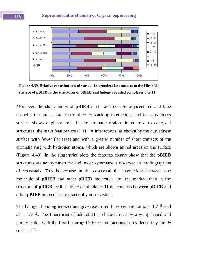
Supramolecular chemistry: Crystal engineering 118
Moreover, the shape index of pBIEB is characterized by adjacent red and blue
triangles that are characteristic of ··· stacking interactions and the curvedness
surface shows a planar zone in the aromatic region. In contrast to cocrystal
structures, the main features are C−H··· interactions, as shown by the curvedness
surface with fewer flat areas and with a greater number of short contacts of the
aromatic ring with hydrogen atoms, which are shown as red areas on the surface
(Figure 4.40). In the fingerprint plots the features clearly show that the pBIEB
structures are not symmetrical and lower symmetry is observed in the fingerprints
of cocrystals. This is because in the co-crystal the interactions between one
molecule of pBIEB and other pBIEB molecules are less marked than in the
structure of pBIEB itself. In the case of adduct 11 the contacts between pBIEB and
other pBIEB molecules are practically non-existent.
The halogen bonding interactions give rise to red lines centered at di = 1.7 Å and
de = 1.9 Å. The fingerprint of adduct 11 is characterized by a wing-shaped and
pointy spike, with the first featuring C−H··· interactions, as evidenced by the de
surface.[57]
Figure 4.39. Relative contributions of various intermolecular contacts to the Hirshfeld
surface of pBIEB in the structures of pBIEB and halogen bonded complexes 8 to 11.
Structure 11
Structure 9
Structure 10a
Structure 10b
Structure 8
pBIEB
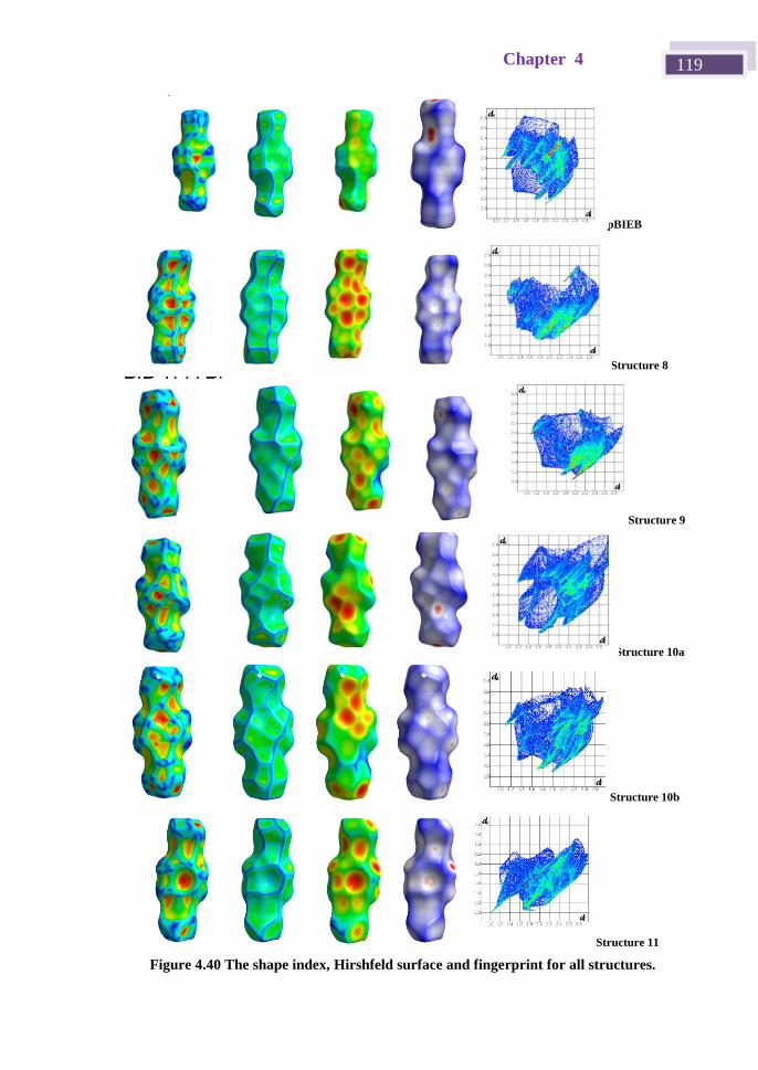
Chapter 4 119
pBIEB
Structure 8
Structure 9
Structure 10a
Structure 10b
Structure 11
Figure 4.40 The shape index, Hirshfeld surface and fingerprint for all structures.
p-BIB TBA Br (2)
p-BIB TPhP Br
p-BIB TBA Br (2)
p-BIB TPhP Br
p-BIB TBA Br (2)
p-BIB TPhP Br
p-BIB TBA Br (2)
p-BIB TPhP Br
p-BIB TBA Br (2)
p-BIB TPhP Br
p-BIB TBA Br (2)
p-BIB TPhP Br
p-BIB TBA Br (2)
p-BIB TPhP Br
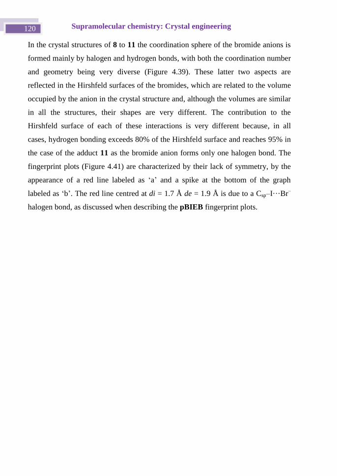
Supramolecular chemistry: Crystal engineering 120
In the crystal structures of 8 to 11 the coordination sphere of the bromide anions is
formed mainly by halogen and hydrogen bonds, with both the coordination number
and geometry being very diverse (Figure 4.39). These latter two aspects are
reflected in the Hirshfeld surfaces of the bromides, which are related to the volume
occupied by the anion in the crystal structure and, although the volumes are similar
in all the structures, their shapes are very different. The contribution to the
Hirshfeld surface of each of these interactions is very different because, in all
cases, hydrogen bonding exceeds 80% of the Hirshfeld surface and reaches 95% in
the case of the adduct 11 as the bromide anion forms only one halogen bond. The
fingerprint plots (Figure 4.41) are characterized by their lack of symmetry, by the
appearance of a red line labeled as ‘a’ and a spike at the bottom of the graph
labeled as ‘b’. The red line centred at di = 1.7 Å de = 1.9 Å is due to a Csp–I···Br–
halogen bond, as discussed when describing the pBIEB fingerprint plots.
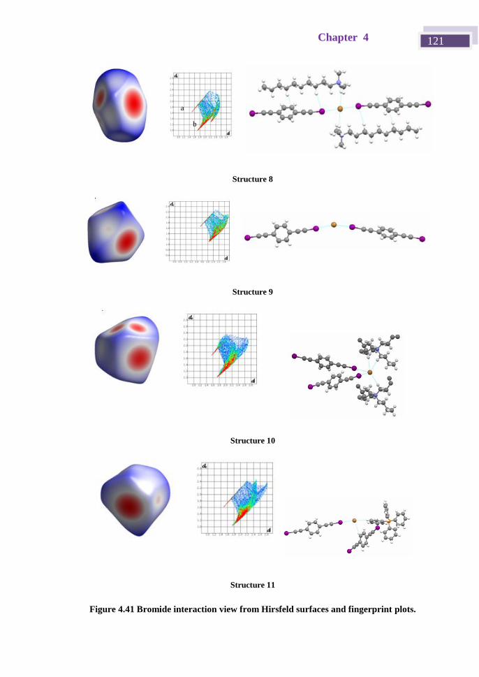
Chapter 4 121
Structure 8
Structure 9
Structure 10
Structure 11
Figure 4.41 Bromide interaction view from Hirsfeld surfaces and fingerprint plots.
a
b
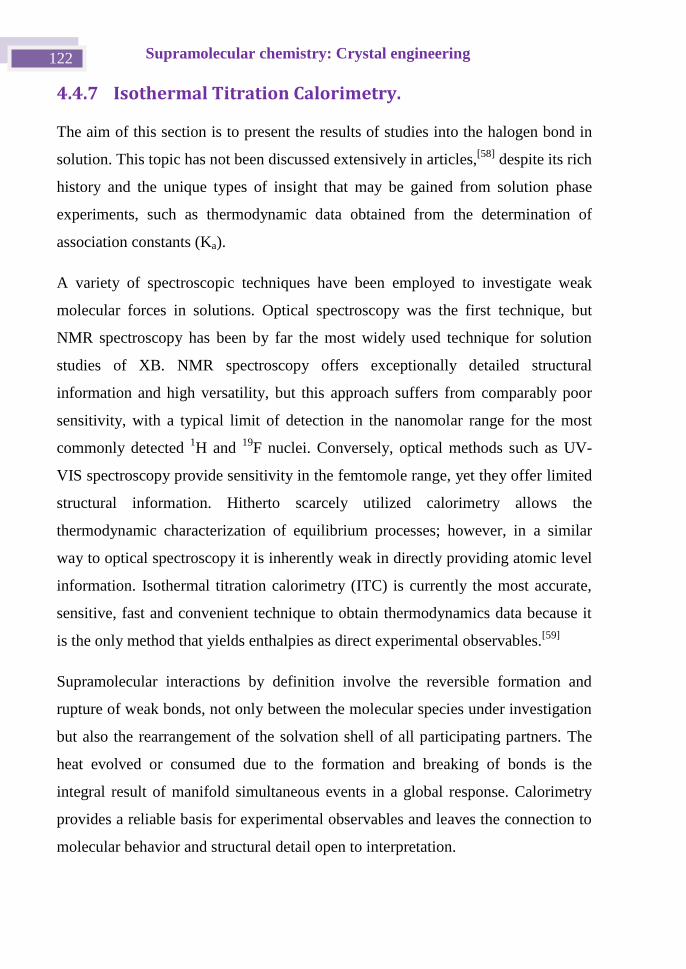
Supramolecular chemistry: Crystal engineering 122
4.4.7 Isothermal Titration Calorimetry.
The aim of this section is to present the results of studies into the halogen bond in
solution. This topic has not been discussed extensively in articles,[58]
despite its rich
history and the unique types of insight that may be gained from solution phase
experiments, such as thermodynamic data obtained from the determination of
association constants (Ka).
A variety of spectroscopic techniques have been employed to investigate weak
molecular forces in solutions. Optical spectroscopy was the first technique, but
NMR spectroscopy has been by far the most widely used technique for solution
studies of XB. NMR spectroscopy offers exceptionally detailed structural
information and high versatility, but this approach suffers from comparably poor
sensitivity, with a typical limit of detection in the nanomolar range for the most
commonly detected 1H and
19F nuclei. Conversely, optical methods such as UV-
VIS spectroscopy provide sensitivity in the femtomole range, yet they offer limited
structural information. Hitherto scarcely utilized calorimetry allows the
thermodynamic characterization of equilibrium processes; however, in a similar
way to optical spectroscopy it is inherently weak in directly providing atomic level
information. Isothermal titration calorimetry (ITC) is currently the most accurate,
sensitive, fast and convenient technique to obtain thermodynamics data because it
is the only method that yields enthalpies as direct experimental observables.[59]
Supramolecular interactions by definition involve the reversible formation and
rupture of weak bonds, not only between the molecular species under investigation
but also the rearrangement of the solvation shell of all participating partners. The
heat evolved or consumed due to the formation and breaking of bonds is the
integral result of manifold simultaneous events in a global response. Calorimetry
provides a reliable basis for experimental observables and leaves the connection to
molecular behavior and structural detail open to interpretation.
Chapter 4 123
The usual ITC procedure is to titrate a solution of compound A, placed in the
calorimetric cell, with aliquots of a solution of compound B placed in an automated
syringe. The exchanged heat is measured and this reveals quantitative information
about the interaction between A and B.[60]
A typical output of an exothermic
encapsulation is depicted in Figure 4.42.
The thermogram shown in Figure 4.42, top graph, shows upward or downward
directed thermal power pulses (as a consequence of each injection) and these reflect
the modulation of the feedback current required to maintain a zero temperature
difference between the sample and the reference cell. The time integration of the
heat pulses when plotted versus the nominal molar ratio of the injected compound
over the one contained in the sample cell yields a titration curve or interaction
isotherm, which is corrected by subtracting the results of a control experiment
(dilution of compound from the syringe into solvent) if necessary. In the lower part
of Figure 4.42 the sigmoidal form allows the determination of the molar enthalpy
Ho from the extrapolated step height or deflection of the curve, the stoichiometry
of the binding process from the position of the inflection point along the molar
ratio axis and the affinity constant Ka from the slope at the inflection point.
Figure 4.42 Thermogram from a typical Isothermal Titration Calorimetry experiment.
0.0 0.5 1.0 1.5 2.0
-1.0
-0.8
-0.6
-0.4
-2
-1
0
1
2
0 20 40 60 80 100 120 140
time (min)
dQ
/dt
(ca
l/s)
Molar Ratio
Q (
kca
l/m
ol o
f in
jecta
nt)
K 1.1 ± 0.1 104 M-1
H -0.6 ± 0.1 kcal/moln 1.00 ± 0.01
Supramolecular chemistry: Crystal engineering 124
To date, the free energies of neutral XB interactions span a range from ~0 to 40 kJ
mol−1
, with the strongest found to involve inorganic XB donors. While numerous
association constant data with inorganic halogen-bond donors exist, there is a
scarcity of quantitative data for organic halogen-bond donors such as haloalkynes
and iodoperfluoro organics.[3b]
Of the few haloalkynes investigated, Laurence and
co-workers proposed a soft basicity scale through the correlation of Δν(C−I)
values, i.e., changes in C−I stretching frequency by IR spectroscopy, with the
formation enthalpy of the iodine complex ΔHI2. Twenty years later, Goroff and co-
workers studied the XB interactions of iodoalkynes in various Lewis basic solvents
by 13
C NMR spectroscopy. Recently, binding constants between
iodoethynylbenzne derivatives and 1-azabicyclo[2.2.2]octane were determined by
1H NMR titrations, with Ka values range from 6.3 ± 0.6 M
−1 for the
dimethylamino-substituted XB donor to 25 ± 8 M−1
for the nitro-substituted analog.
A van’t Hoff analysis of these data showed that the XB association is promoted by
a favorable negative enthalpic term ΔH, which is partially compensated by an
unfavorable negative entropic term TΔS.[31]
Studies of halogen bond binding in solution by ITC of iodoethynyl derivatives have
not been reported to date and most published studies employed cationic halogen
bond donors such as 2-iodoimidazolium[61]
or iodo-1,2,3-triazoliums.[62]
We
conducted isothermal calorimetric titrations in THF to investigate the halogen-bond
strength of the bidentate p-bis(iodoethynyl)benzene halogen-bond donor toward the
bromide anion in solution. In the three cases examined, the binding of pBIEB to
bromide is always found to be entropically driven, which may indicate a significant
desolvation process with the release of solvent molecules to the bulk solution. The
binding affinities, which are gathered in Table 4.12, showed little dependency on
the weakly coordinating counteranions of bromide salts, but became slightly
stronger with a higher solubility salt (decyltrimethylammonium (8.3 103
M–1
) >
tetrabutylammonium (7.9 103
M–1
) > tetrapropylammonium (2.8 103
M–1
)). (See
Figure 4.43)
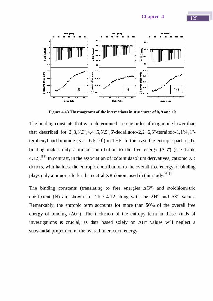
Chapter 4 125
Figure 4.43 Thermograms of the interactions in structures of 8, 9 and 10
The binding constants that were determined are one order of magnitude lower than
that described for 2',3,3',3'',4,4'',5,5',5'',6'-decafluoro-2,2'',6,6''-tetraiodo-1,1':4',1''-
terphenyl and bromide (Ka = 6.6 104) in THF. In this case the entropic part of the
binding makes only a minor contribution to the free energy (Gº) (see Table
4.12).[53]
In contrast, in the association of iodoimidazolium derivatives, cationic XB
donors, with halides, the entropic contribution to the overall free energy of binding
plays only a minor role for the neutral XB donors used in this study.[61b]
The binding constants (translating to free energies ∆G°) and stoichiometric
coefficient (N) are shown in Table 4.12 along with the ∆H° and ∆S° values.
Remarkably, the entropic term accounts for more than 50% of the overall free
energy of binding (∆G°). The inclusion of the entropy term in these kinds of
investigations is crucial, as data based solely on ∆H° values will neglect a
substantial proportion of the overall interaction energy.
10 9 8
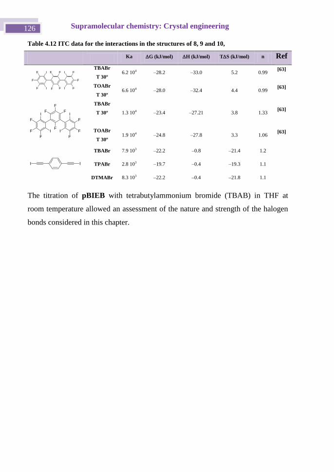
Supramolecular chemistry: Crystal engineering 126
Table 4.12 ITC data for the interactions in the structures of 8, 9 and 10,
Ka G (kJ/mol) H (kJ/mol) TS (kJ/mol) n Ref
F
F
F I
I
F
F F
F
I
I
F
F
F
TBABr
T 30º 6.2 104 –28.2 –33.0 5.2 0.99
[63]
TOABr
T 30º 6.6 104 –28.0 –32.4 4.4 0.99
[63]
F
F F
FF
F
I
F
I
F
IF
F
I
TBABr
T 30º
1.3 104 –23.4 –27.21 3.8 1.33 [63]
TOABr
T 30º 1.9 104 –24.8 –27.8 3.3 1.06
[63]
II
TBABr 7.9 103 –22.2 –0.8 –21.4 1.2
TPABr 2.8 103 –19.7 –0.4 –19.3 1.1
DTMABr 8.3 103 –22.2 –0.4 –21.8 1.1
The titration of pBIEB with tetrabutylammonium bromide (TBAB) in THF at
room temperature allowed an assessment of the nature and strength of the halogen
bonds considered in this chapter.
Chapter 4 127
4.5 Conclusions
In this chapter we have described eleven structures of bis(haloethynyl)benzene
halogen bonded complexes with nitrogen, oxygen and halide bases. This
information, together with the analysis of Hirshfeld surfaces and quantum chemical
calculations, allowed us to establish that pBIEB, pBBrEB and mBIEB are strong
ditopic XB donors and this makes them very useful in the supramolecular geometry
based design.
The Csp−I···N XB distance depends on the nitrogen atom hybridization and
decreases following the trend from sp to sp3 to sp
2. In addition, the electronic
distribution of the haloethynyl group shows cylindrical nucleophilic areas around
the ethynyl and halogen atom and this allows the formation of edge-to-edge
Csp2−H···X and Csp2−H···(alkyne) hydrogen bonds with a hydrogen of an aromatic
ring. This possibility precludes the adoption of a herringbone type organization.
The stabilization energy of these supramolecular structures ranges from 2.9 to 5.7
kcal mol–1
. In spite of these weak energies, their effects on the crystal structure and
packing are relevant and, in combination with strong halogen bonds, they provide a
useful strategy for the formation of two-dimensional arrangements in cocrystals
with nitrogen and oxygen XB acceptors, which are of great interest in the
development of molecular organic materials.
ITC is a useful tool to study halogen bond interactions and this helped us to
understand the coordination sphere of, in this case, bromide.
Supramolecular chemistry: Crystal engineering 128
4.6 Experimental
All of the general halogen bond acceptors were used as received from commercial
sources. The molecule pBBrEB was synthesized in the same way as pBIEB: N-
Bromosuccinimide (4.14 g, 36.2 mmol) and silver nitrate (0.62 g, 3.62 mmol) were
added successively to a solution of 1,4-diethynylbenzene (2.28 g 18.1 mmol). The
reaction mixture was stirred at 0 ºC for 5 h. The crude product was filtered off and
washed with diethyl ether. The solvent was removed under reduce pressure. The
residue was dissolved in water (50 mL) and extracted with dichloromethane (3 × 50
mL). The organic layer was dried over Mg2SO4 and the solvent was evaporated.
The pure product was recovered as yellow solid (5.13 g, 75%).
1H NMR (300 MHz, CDCl3): δ .38 (s, 4H).
4.6.1 Crystal synthesis and characterization
All crystal syntheses were carried out at ambient temperature in
chloroform/dichloromethane in a1:1 molar ratio.
4.6.2 X-ray monocrystal diffraction.
The crystals are air stable and were mounted on the tip of a glass fiber with epoxy
cement. X-ray diffraction experiments were carried out on an Oxford-diffraction
Xcalibur S diffractometer. Data were collected at 2 3 K and 1 0 K with Mo Kα
radiation. The software package CrysAlys was used to process data.
Final cell parameters were obtained by global refinement of reflections obtained
from integration of all frames data. The structures were solved by direct methods
and refined by the full-matrix method based on F2 using the SHELXTL program.
The non-hydrogen atoms of structures were refined anisotropically, the hydrogen
atoms were observed in difference electron density maps and refined isotropically.
The crystal parameters and basic information relating data collection and structure
refinement for the compounds are summarized in Table 4.13 and Table 4.14.
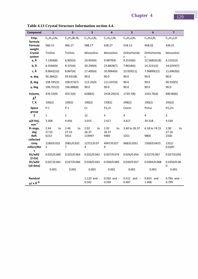
Chapter 4 129
Table 4.13 Crystal Structure Information section 4.4.
Compound 1 2 3 4 5 6 7
Emp. formula
C22H14I2N2 C22H14Br2N2 C22H14I2N4 C27H22I2N2 C16H16I2N4 C14H8I2N2 C13H10I2O
Formula weight
560.15 466.17 588.17 628.27 518.13 458.02 436.01
Crystal system
Triclinic Triclinic Monoclinic Monoclinic Orthorhombic
Orthorhombic
Monoclinic
a, Å 7.1304(8) 6.905(3) 19.450(4) 9.9879(4) 9.2510(6) 12.56832(18) 4.2101(2)
b, Å 8.3566(9) 8.325(4) 20.200(4) 23.8828(7) 7.8618(4) 14.3151(2) 14.0293(7)
c, Å 8.9642(10) 8.847(4) 17.400(4) 10.9064(4) 23.920(11) 7.96899(12) 11.6962(6)
α, deg 94.384(2) 93.931(8) 90.0 90.0 90.0 90.0 90.0
β, deg 108.595(2) 108.073(7) 113.10(3) 111.637(4) 90.0 90.0 90.593(5)
γ, deg 106.701(2) 106.888(8) 90.0 90.0 90.0 90.0 90.0
Volume,
Å3
476.52(9) 455.5(4) 6288(2) 2418.29(15) 1739.7(8) 1433.76(4) 690.80(6)
T, K 100(2) 100(2) 100(2) 150(2) 298(2) 100(2) 293(2)
Space group
P-1 P-1 Cc P21/n Cmcm Pnma P21/m
Z 1 1 12 4 4 4 2
μ(X Kα), mm-1
3.308 4.456 3.015 2.617 3.617 34.318 4.530
θ range, deg
2.44 to 27.55
2.46 to 27.53
2.02 to 26.37
2.92 to 26.37
3.40 to 26.37 6.18 to 74.15 2.90 to 27.16
Refl. collected
6153 5915 119497 9485 5351 9800 2330
Uniq reflect/Rin
t
2189/0.0322
2081/0.0327
12721/0.074
4947/0.0279
968/0.0351 1509/0.0415 1322/ 0.0287
R1/wR2 [I>2σ]
0.025/0.060 0.025/0.064 0.022/0.042 0.037/0.074 0.024/0.054 0.027/0.067 0.027/0.056
R1/wR2 (all data)
0.027/0.061 0.027/0.066 0.028/0.043 0.058/0.083 0.039/0.057 0.0284/0.068 0.0350/0.060
0.001 0.001 0.003 0.001 0.001 0.001 0.001
Residual
ρ/ e Å-3
1.110 and -0.542
0.592 and -0.599
0.512 and -0.407
0.853 and -1.968
0.785 and -0.799
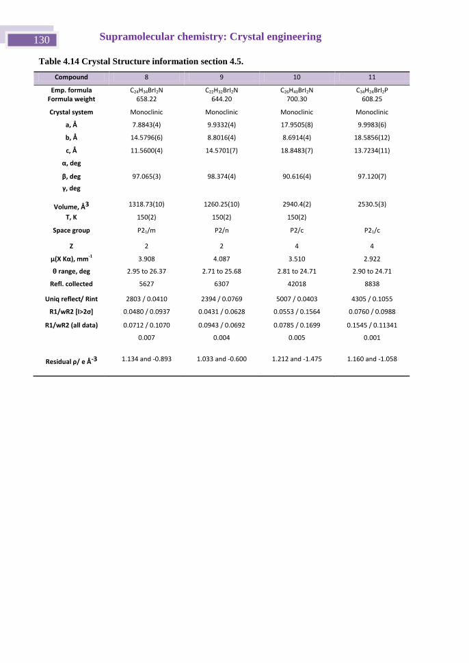
Supramolecular chemistry: Crystal engineering 130
Table 4.14 Crystal Structure information section 4.5.
Compound 8 9 10 11
Emp. formula C24H34BrI2N C22H32BrI2N C26H40BrI2N C34H24BrI2P Formula weight 658.22 644.20 700.30 608.25
Crystal system Monoclinic Monoclinic Monoclinic Monoclinic
a, Å 7.8843(4) 9.9332(4) 17.9505(8) 9.9983(6)
b, Å 14.5796(6) 8.8016(4) 8.6914(4) 18.5856(12)
c, Å 11.5600(4) 14.5701(7) 18.8483(7) 13.7234(11)
α, deg
β, deg 97.065(3) 98.374(4) 90.616(4) 97.120(7)
γ, deg
Volume, Å3 1318.73(10) 1260.25(10) 2940.4(2) 2530.5(3)
T, K 150(2) 150(2) 150(2)
Space group P21/m P2/n P2/c P21/c
Z 2 2 4 4
μ(X Kα), mm-1 3.908 4.087 3.510 2.922
θ range, deg 2.95 to 26.37 2.71 to 25.68 2.81 to 24.71 2.90 to 24.71
Refl. collected 5627 6307 42018 8838
Uniq reflect/ Rint 2803 / 0.0410 2394 / 0.0769 5007 / 0.0403 4305 / 0.1055
R1/wR2 [I>2σ] 0.0480 / 0.0937 0.0431 / 0.0628 0.0553 / 0.1564 0.0760 / 0.0988
R1/wR2 (all data) 0.0712 / 0.1070 0.0943 / 0.0692 0.0785 / 0.1699 0.1545 / 0.11341
0.007 0.004 0.005 0.001
Residual ρ/ e Å-3 1.134 and -0.893 1.033 and -0.600 1.212 and -1.475 1.160 and -1.058
Chapter 4 131
4.7 Hirshfeld Surfaces
Hirshfeld surfaces and the associated fingerprint plots were calculated using
CrystalExplorer,[43]
which accepts a structure input file in the CIF format. Bond
lengths to hydrogen atoms were set to typical values (C–H = 1.083 Å, N–H = 1.009
Å, O–H = 0.983 Å). The distance from the Hirshfeld surface to the nearest atoms
outside and inside the surface are characterized by the quantities de and di,
respectively, and the normalized contact distance based on these, dnorm = (di –
rivdW
)/ rivdW
+(de – revdW
)/ revdW
), with rivdW
and revdW
being the van der Waals radii
of the atoms. The 2D histograms, fingerprint plot distance external to the surface
(de) versus distance internal to the surface (di) is the distance from the surface to
the nearest atom in the molecule itself.
Supramolecular chemistry: Crystal engineering 132
4.8 Computational Methods.
Quantum chemical calculations were performed using the Gaussian 09[64]
suite of
programs. Geometry optimizations were carried out in the gas phase with the
B98[65]
method, employing the 6-311G+(d,p)[66]
basis set for all atoms except
iodine, for which the DGDZVP[67]
basis set was used. Geometry optimizations
were carried out without constraints, using the default convergence criteria for the
Gaussian software. The natural bond orbital (NBO) analysis[68]
using the NBO
module contained in the Gaussian 09 program were performed on the basis of the
minimized structures in order to calculate the NBO charges. The resulting
electronic energies of interaction were corrected for scale (0.9884),[69]
zero point
differences and for basis set superposition errors.
Chapter 4 133
4.9 Bibliography
[1] a) C. B. Aakeröy and N. Schultheiss in Assembly of Molecular Solids via Non-
covalent Interactions, Vol. Making Crystals by Design Eds.: D. Braga and F.
Grepioni), Wiley-VCH verlag GmbH & Co. KGaA, Weinheim, 2007, pp. 209-240;
b) J. Chisholm, E. Pidcock, J. Van De Streek, L. Infantes, S. Motherwell and F. H.
Allen, Crystengcomm 2006, 8, 11-28; c) M. J. Zaworotko, Crystal Growth &
Design 2007, 7, 4-9; d) J. D. Wuest, Chem. Comm. 2005, 5830-5837.
[2] G. R. Desiraju, Angew. Chem. Int. Ed. 2007, 46, 8342-8356.
[3] a) R. W. Troff, T. Makela, F. Topic, A. Valkonen, K. Raatikainen and K.
Rissanen, Eur. J. Org. Chem. 2013, 1 1 −1 3 b) L. C. Gilday, S. . obinson,
T. A. Barendt, M. J. Langton, B. R. Mullaney and P. D. Beer, Chem. Rev. 2015,
115, 7118-7195; c) P. Kratzer, B. Ramming, S. Roemisch and G. Maas,
Crystengcomm 2015, 17, 448 −44 4 d) K. Bouchmella, B. Boury, S. G. Dutremez
and A. van der Lee, Chem. Eur. J. 2007, 13, 6130-6138; e) K. Rissanen,
Crystengcomm 2008, 10, 1107-1113; f) N. Busschaert, C. Caltagirone, W. Van
Rossom and P. A. Gale, Chem. Rev. 2015, 115, 8038−81 g) C. B. Aakeroy, N.
Schultheiss, J. Desper and C. Moore, CrystEngComm 2007, 9, 421-426; h) A. C. B.
Lucassen, M. Vartanian, G. Leitus and M. E. van der Boom, Cryst. Growth Des.
2005, 5, 1 1−1 3.
[4] T. Imakubo, T. Shirahata, K. Herve and L. Ouahab, J. Mat. Chem. 2006, 16,
162-173.
[5] J. E. Anthony in Engineered Pentacenes, Vol. Wiley-VCH Verlag GmbH &
Co. KGaA, 2006, pp. 58-74.
[6] J.-H. Dou, Y.-Q. Zheng, Z.-F. Yao, Z.-A. Yu, T. Lei, X. Shen, X.-Y. Luo, J.
Sun, S.-D. Zhang, Y.-F. Ding, G. Han, Y. Yi, J.-Y. Wang and J. Pei, J. Am. Chem.
Soc. 2015, 137, 15947-15956.
[7] A. Putta, J. D. Mottishaw, Z. Wang and H. Sun, Cryst. Growth Des. 2014, 14,
350-356.
[8] R. B. Walsh, C. W. Padgett, P. Metrangolo, G. Resnati, T. W. Hanks and W. T.
Pennington, Cryst. Growth Des. 2001, 1, 165-175.
[9] D. Cincic, T. Friscic and W. Jones, Chem. Eur. J. 2008, 14, 747-753.
[10] M. Fourmigue, P. Metrangolo and G. Resnati, Halogen Bonding
Fundamentals and Applications, 2008, p.
[11] a) N. S. Goroff, S. M. Curtis, J. A. Webb, F. W. Fowler and J. W. Lauher,
Org. Lett. 2005, 7, 1891-1893; b) A. W. Sun, J. W. Lauher and N. S. Goroff,
Science 2006, 312, 1030-1034; c) L. Luo, C. Wilhelm, A. Sun, C. P. Grey, J. W.
Lauher and N. S. Goroff, J. Am. Chem. Soc. 2008, 130, 7702-7709; d) C. Wilhelm,
S. A. Boyd, S. Chawda, F. W. Fowler, N. S. Goroff, G. P. Halada, C. P. Grey, J. W.
Lauher, L. Luo, C. D. Martin, J. B. Parise, C. Tarabrella and J. A. Webb, J. Am.
Chem. Soc. 2008, 130, 4415-4420.
[12] a) A. L. Barres, A. El-Ghayoury, L. V. Zorina, E. Canadell, P. Auban-Senzier
and P. Batail, Chem. Commun. 2008, 2194-2196; b) J. Lieffrig, O. Jeannin and M.
Supramolecular chemistry: Crystal engineering 134
Fourmigue, J. Am. Chem. Soc. 2013, 135, 6200-6210; c) E. Bosch, Cryst. Growth
Des. 2014, 14, 126-130; d) K. Eichstaedt, B. Wicher, M. Gdaniec and T. Polonski,
CrystEngComm 2016, 18, 5807-5810.
[13] C. B. Aakeroy, M. Fasulo, N. Schultheiss, J. Desper and C. Moore, J. Am.
Chem. Soc. 2007, 129, 13772-13773.
[14] S. Tothadi and G. R. Desiraju, Chem. Commun. 2013, 49, 7791-7793.
[15] L. Meazza, J. A. Foster, K. Fucke, P. Metrangolo, G. Resnati and J. W. Steed,
Nature Chem. 2013, 5, 42−4 .
[16] K. Raatikainen and K. Rissanen, Chem. Sci. 2012, 3, 1235-1239.
[17] A. Linke, S. H. Jungbauer, S. M. Huber and S. R. Waldvogel, Chem.
Commun. 2015, 51, 2040-2043.
[18] S. H. Jungbauer, S. M. Walter, S. Schindler, L. Rout, F. Kniep and S. M.
Huber, Chem. Commun. 2014, 50, 6281-6284.
[19] a) J. L. Syssa-Magale, K. Boubekeur, P. Palvadeau, A. Meerschaut and B.
Schollhorn, CrystEngComm 2005, 7, 302-308; b) C. B. Aakeroey, D. Welideniya,
J. Desper and C. Moore, CrystEngComm 2014, 16, 10203-10209.
[20] T. Caronna, R. Liantonio, T. A. Logothetis, P. Metrangolo, T. Pilati and G.
Resnati, J. Am. Chem. Soc. 2004, 126, 4500.
[21] M. Fourmigue, Curr. Opin., Solid State Mater. Sci. 2009, 13, 36-45.
[22] R. Bianchi, A. Forni and T. Pilati, Chemistry – A European Journal 2003, 9,
1631-1638.
[23] a) D. L. Reger, J. R. Gardinier, S. Bakbak, R. F. Semeniuc, U. H. F. Bunz and
M. D. Smith, New J. Chem. 2005, 29, 1035-1043; b) T. Steiner and M. Tamm, J.
Organomet. Chem. 1998, 570, 235–239.
[24] a) W. Lu, M. C. W. Chan, N. Zhu, C. M. Che, Z. He and K. Y. Wong, Chem.
Eur. J. 2003, 9, 6155 - 6166; b) A. Holme, K. J. Børve, L. J. Sæthre and T. D.
Thomas, J. Phys. Chem. A 2013, 117, 200 −201 .
[25] a) C. J. McAdam, S. A. Cameron, L. R. Hanton, A. R. Manning, S. C. Moratti
and J. Simpson, CrystEngComm 2012, 14, 4369–4383; b) Y. Hu, Z. Li, Y. Zhao, Y.
Yang, F. Liu and L. Wang, RSC Adv. 2015, 5, 102 –1028 c) E. Guzm n-
Perc stegui, J. G. Alvarado- odr guez, J. Cruz-Borbolla, N. Andrade-López, . A.
V z uez-García, R. N. Nava-Galindo and T. Pandiyan, Cryst. Growth Des. 2014,
14, 3 42−3 .
[26] G. R. Desiraju, Cryst. Growth Des. 2011, 11, 896–898.
[27] A. Forni, P. Metrangolo, T. Pilati and G. Resnati, Cryst. Growth Des. 2004, 4,
291-295.
[28] A. De Santis, A. Forni, R. Liantonio, P. Metrangolo, T. Pilati and G. Resnati,
Chem. Eur. J. 2003, 9, 3974-3983.
[29] C. B. Aakeroey, M. Baldrighi, J. Desper, P. Metrangolo and G. Resnati, Chem.
Eur. J. 2013, 19, 16240-16247.
[30] C. B. Aakeroey, P. D. Chopade and J. Desper, Cryst. Growth Des. 2013, 13,
4145-4150.
[31] O. Dumele, D. Wu, N. Trapp, N. Goroff and F. Diederich, Org. Lett. 2014, 16,
4 22−4 2 .
Chapter 4 135
[32] J. L. Syssa-Magale, K. Boubekeur and B. Schollhorn, J. Mol. Struct. 2005,
737, 103-107.
[33] C. Perkins, S. Libri, H. Adams and L. Brammer, CrystEngComm 2012, 14,
3033-3038.
[34] L. Gonzalez, N. Gimeno, R. Maria Tejedor, V. Polo, M. Blanca Ros, S. Uriel
and J. Luis Serrano, Chem. Mat. 2013, 25, 4503-4510.
[35] R. B. Walsh, C. W. Padgett, P. Metrangolo, G. Resnati, T. W. Hanks and W.
T. Pennington, Cryst. Growth Des. 2001, 1, 165 - 175.
[36] O. V. Runarsson, J. Artacho and K. Warnmark, European J. Org. Chem. 2012,
7015-7041.
[37] E. Bosch, Cryst. Growth Des. 2014, 14, 126.
[38] a) S. Sergeyev, Helv. Chim. Acta 2009, 92, 415-444; b) B. Dolensky, M.
Havlik and V. Kral, Chem. Soc. Rev. 2012, 41, 3839-3858.
[39] a) X. Du, Y. Sun, B. Tan, Q. Teng, X. Yao, C. Su and W. Wang, Chem
Commun 2010, 46, 970-972; b) M. Carta, R. Malpass-Evans, M. Croad, Y. Rogan,
J. C. Jansen, P. Bernardo, F. Bazzarelli and N. B. McKeown, Science 2013, 339,
303-307.
[40] S. Satishkumar and M. Periasamy, Tetrahedron: Asymmetry 2006, 17, 1116–
1119.
[41] J. T. Cross, N. A. Rossi, M. Serafin and K. A. Wheeler, CrystEngComm 2014,
16, 7251.
[42] S. K. Wolff, D. J. Grimwood, J. J. McKinnon, M. J. Turner, D. Jayatilaka and
M. A. Spackman in CrystalExplorer 3.0, Vol. (Ed. C. 3.0), University of Western
Australia, 2012.
[43] M. A. Spackman and D. Jayatilaka, CrystEngComm 2009, 11, 19-32.
[44] N. H. Evans and P. D. Beer, Angew. Chem. Int. Ed. 2014, 53, 11716-11754.
[45] a) G. Cavallo, P. Metrangolo, T. Pilati, G. Resnati, M. Sansotera and G.
Terraneo, Chem. Soc. Rev. 2010, 39, 3772-3783; b) A. Caballero, N. G. White and
P. D. Beer, Angew. Chem. Int. Ed. 2011, 50, 1845-1848; c) A. Caballero, F. Zapata,
N. G. White, P. J. Costa, V. Felix and P. D. Beer, Angew. Chem. Int. Ed. 2012, 51,
1876-1880; d) P. Metrangolo, T. Pilati, G. Terraneo, S. Biella and G. Resnati,
CrystEngComm 2009, 11, 1187-1196; e) G. Cavallo, S. Biella, J. A. Lu, P.
Metrangolo, T. Pilati, G. Resnati and G. Terraneo, J. Fluorine Chem. 2010, 131,
1165-1172.
[46] A. Abate, S. Biella, G. Cavallo, F. Meyer, H. Neukirch, P. Metrangolo, T.
Pilati, G. Resnati and G. Terraneo, J. Fluorine Chem. 2009, 130, 1171-1177.
[47] H. M. Yamamoto, Y. Kosaka, R. Maeda, J. Yamaura, A. Nakao, T. Nakamura
and R. Kato, ACS Nano 2008, 2, 143-155.
[48] J. Lieffrig, A. G. Niassy, O. Jeannin and M. Fourmigue, CrystEngComm 2015,
17, 0− .
[49] J. Grebe, G. Geiseler, K. Harms and K. Dehnicke, Z. Naturforsch. B Chem.
Sci. 1999, 54, 77-86.
[50] A. Abate, J. Marti-Rujas, P. Metrangolo, T. Pilati, G. Resnati and G. Terraneo,
Cryst. Growth Des. 2011, 11, 4220-4226.
Supramolecular chemistry: Crystal engineering 136
[51] S. Triguero, R. Llusar, V. Polo and M. Fourmigue, Cryst. Growth Des. 2008,
8, 2241-2247.
[52] J. Lieffrig, O. Jeannin and M. Fourmigué, J. Am. Chem. Soc. 2013, 135, 6200.
[53] S. H. Jungbauer, S. Schindler, E. Herdtweck, S. Keller and S. M. Huber,
Chemistry 2015, 21, 13625-13636.
[54] A. Abate, J. Marti-Rujas, P. Metrangolo, T. Pilati, G. Resnati and G. Terraneo,
Cryst. Growth Des. 2011, 11, 4220−422 .
[55] S. C. Nyburg and C. H. Faerman, Acta Crystallogr., Sect. B: Struct. Commun.
1985, 41, 274-279.
[56] a) A. Abate, S. Biella, G. Cavallo, F. Meyer, H. Neukirch, P. Metrangolo, T.
Pilati, G. Resnati and G. Terraneo, J. Fluor. Chem. 2009, 130, 11 1−11 b) P.
Metrangolo, Y. Carcenac, M. Lahtinen, T. Pilati, K. Rissanen, A. Vij and G.
Resnati, Science 2009, 323, 1461-1464.
[57] J. J. McKinnon, M. A. Spackman and A. S. Mitchell, Acta Crystallogr. B
2004, 60, 627-668.
[58] M. Erdelyi, Chem. Soc. Rev. 2012, 41, 3547-3557.
[59] a) A. Velazquez-Campoy and E. Freire, Nat. Protoc. 2006, 1, 186-191; b) A.
Velazquez-Campoy, S. A. Leavitt and E. Freire, Methods Mol. Biol. 2015, 1278,
183-204.
[60] A. Arnaud and L. Bouteiller, Langmuir 2004, 20, 6858-6863.
[61] a) S. M. Walter, F. Kniep, L. Rout, F. P. Schmidtchen, E. Herdtweck and S.
M. Huber, J. Am. Chem. Soc. 2012, 134, 8507-8512; b) S. Chakraborty, R. Dutta
and P. Ghosh, Chem. Commun. 2015, 51, 14793-14796; c) S. H. Jungbauer and S.
M. Huber, J. Am. Chem. Soc. 2015, 137, 12110-12120.
[62] R. Tepper, B. Schulze, M. Jager, C. Friebe, D. H. Scharf, H. Gorls and U. S.
Schubert, J. Org. Chem. 2015, 80, 3139-3150.
[63] S. H. Jungbauer, S. Schindler, E. Herdtweck, S. Keller and S. M. Huber,
Chem. Eur. J. 2015, 21, 13625-13636.
[64] G. W. T. J. Frisch, H. B. Schlegel, G. E. Scuseria, M. A. Robb, J. R.
Cheeseman, G. Scalmani, V. Barone, G. A. Petersson, H. Nakatsuji, X. Li, M.
Caricato, A. Marenich, J. Bloino, B. G. Janesko, R. Gomperts, B. Mennucci, H. P.
Hratchian, J. V. Ortiz, A. F. Izmaylov, J. L. Sonnenberg, D. Williams-Young, F.
Ding, F. Lipparini, F. Egidi, J. Goings, B. Peng, A. Petrone, T. Henderson, D.
Ranasinghe, V. G. Zakrzewski, J. Gao, N. Rega, G. Zheng, W. Liang, M. Hada, M.
Ehara, K. Toyota, R. Fukuda, J. Hasegawa, M. Ishida, T. Nakajima, Y. Honda, O.
Kitao, H. Nakai, T. Vreven, K. Throssell, J. A. Montgomery, Jr., J. E. Peralta, F.
Ogliaro, M. Bearpark, J. J. Heyd, E. Brothers, K. N. Kudin, V. N. Staroverov, T.
Keith, R. Kobayashi, J. Normand, K. Raghavachari, A. Rendell, J. C. Burant, S. S.
Iyengar, J. Tomasi, M. Cossi, J. M. Millam, M. Klene, C. Adamo, R. Cammi, J. W.
Ochterski, R. L. Martin, K. Morokuma, O. Farkas, J. B. Foresman, and D. J. Fox,
in Gaussian 09, Vol. Gaussian Inc., Wallingford CT, 2009.
[65] a) P. M. W. Gill, Mol. Phys. 1996, 89, 433-445; b) J. P. Perdew, K. Burke and
M. Ernzerhof, Phys. Rev. Lett. 1996, 77, 3865-3868.
Chapter 4 137
[66] W. J. Hehre, L. Radom, S. P. V. R. and J. A. Pople in Ab initio Molecular
Orbital Theory, Vol. Wiley, New York, 1986.
[67] N. Godbout, D. R. Salahub, J. Andzelm and E. Wimmer, Can. J. Chem. 1992,
70, 560-571.
[68] A. E. Reed, L. A. Curtiss and F. Weinhold, Chem. Rev. 1988, 88, 899-926.
[69] J. P. Merrick, D. Moran and L. Radom, J. Phys. Chem. A 2007, 111, 11683-
11700.


Chapter 5 Liquid Crystals: Promesogenic
Calamitic, Bent-core and Discotic Shapes
by Halogen Bonding.

Chapter 5 141
5.1 Introduction
Liquid Crystals is an interesting research field that involves both Materials and Life
Sciences. The first document dealing with the liquid crystal state appeared in 1888
when F. Reinitzer sent a letter to Professor O. Lehmann describing the mesogenic
properties of some cholesterol derivatives. Today this field remains of great interest
in the scientific community due to the unique properties of these materials.[1]
Liquid Crystals are known as ‘The Fourth State of the Matter’ and their properties
are related to their name. The concept of ‘liquid crystal’ does not seem to be
logical. The term seems to suggest that a liquid crystal is an intermediate state
between the liquid and the crystal. In fact, Liquid Crystals have some typical
properties of a liquid – such as fluidity, inability to support shear, the formation
and coalescence of droplets – as well some properties of crystals, such as
anisotropy in optical, electrical, and magnetic properties, periodic arrangement of
molecules in one spatial direction, etc.[2]
Today Liquid Crystals are ubiquitous and
appear in fields as diverse as electrooptic displays, thermometry, optical imaging,
nondestructive mechanical testing of materials under stress, bioinspired materials,
biotic-abiotic interfaces, dynamic materials, interfacial protein assemblies,
mesomorphic lipid assemblies, and polymeric multilayers, amongst others.[3]
Liquid crystals are part of supramolecular chemistry and, in fact, they represent one
example of self-organized structures obtained by spontaneous associations of
molecules. In the mesomorphic state shown by these materials, the molecules have
different organizations that are stabilized by non-covalent interactions, which are
are generally weaker forces than, for example, van der Waals forces, -
interactions, dipolar interactions, H-bonds etc.[4]
Most of the tens of thousands of
liquid crystalline compounds described to date are single molecules, but in recent
years a growing number of papers dealing with ‘supermolecules’ that form li uid
crystals have appeared in the literature. These supermolecules or complexes are
formed by the self-assembly of different building blocks by means of weak
Liquid Crystals: Promesogenic Calamitic, Bent-core and Discotic
Shapes by Halogen Bonding 142
interactions in a combination of the two different types of supramolecular
approaches: Self-assembly & self-organization. Most of these supramolecular
organizations are formed by ionic or H-bonding interactions.[5]
Taking into account that one of the main objectives of the work described in this
doctoral thesis is the study of supramolecular systems based on halogen bonding
interactions, we decided to use halogen bonding as an alternative approach to
hydrogen bonding to obtain liquid crystalline materials.
Prior to planning the synthesis of specific materials it was necessary to carry out an
in-depth review of the literature in this area. A summary of this review is provided
in the next section.
Chapter 5 143
5.2 Previous works
Non-covalent interactions (hydrogen bonding, van der Waals forces, -
interactions, ionic interactions, etc.) have become an extraordinary and versatile
tool to generate numerous original and attractive supramolecular architectures and
functionalities in different fields. Among them, it is worth highlighting the
remarkable evolution of hydrogen bonding from being a curious intermolecular
interaction between a hydrogen atom and an electron-rich partner to being a
powerful tool for molecular control of protein and DNA chemistry, crystal
engineering of solid-state materials and also in soft matter assemblies. Regarding
soft materials, the use of hydrogen bonding is quite widespread in the field of
liquid crystals, in which it has been successfully used to prepare functional
materials with varied mesomorphic organizations.[6]
Although pioneering studies
were focused on preparing calamitic and discotic hydrogen-bonded liquid
crystals,[7]
bent-shaped liquid crystals have recently been obtained using this
strategy.[8]
An alternative approach to hydrogen bonding (HB) is halogen bonding (XB).[9]
Indeed, a great deal of research has recently been carried out with the aim of
understanding and harnessing this type of non-covalent interaction, which involves
pairing a halogen atom with an electron-rich partner. Although the halogen bond
was described more than 150 years ago,[10]
it was not until the seventies that Hassel
highlighted the ability of this interaction to manage self-assembly processes.[11]
During the past decade, many applications of halogen bonding in fields as diverse
as crystal engineering, enantiomer separation, biology and supermolecular
architectures have been reported and reviewed.[12]
This non-covalent interaction
exhibits similar characteristics to HB in directionality and strength and may
cooperate with, or prevail over, HB – as mentioned in previous chapters.[13]
Liquid Crystals: Promesogenic Calamitic, Bent-core and Discotic
Shapes by Halogen Bonding 144
5.2.1 Liquid crystals: Properties and classification
In a liquid crystal the crystallinity or the high order in the structure is reduced and
this gives the molecule some degree of mobility. The order in the liquid crystal is
dominated by the molecular orientation, i.e., the molecules align parallel to each
other to minimize the excluded volume and maximize the attractive intermolecular
interactions. In liquid crystalline materials the different properties are dependent on
the direction in which they are measured (optical, electric, magnetic and
mechanical). Moreover, the mobility of the molecules in the liquid crystal
mesophase enables such assemblies to respond to different types of external stimuli
and allows ‘self-healing’ of defects.[6b]
All of these properties are strongly related
to the molecular structure, which controls the molecular interactions.
Liquid Crystals (LC) can be classified as being either thermotropic, where the
liquid crystalline phases are achieved by varying the temperature of the system, or
as lyotropic, where variation of the concentration of the constituents in a solvent
leads to the liquid crystalline phases.
In thermotropic LCs (discussed in this chapter), on heating the material above its
melting point (Tm) the thermal motion of the molecules has increased to such an
extent that the material passes from the solid phase to the liquid crystal phase,
which is also known as a mesophase. On increasing the temperature further the
molecular mobility increases and either less ordered mesophases or the isotropic
liquid may be formed.
Liquid crystalline compounds are commonly called ‘mesogenic’ materials and
‘mesomorphism’ describes their ability to form liquid crystal phases. In
thermotropic liquid crystals the melting point is defined as the temperature of the
transition between the last crystalline organization of the compounds and the first
mesophase that appears in the heating process. In this process the transition
temperature between the last mesophase observed and the isotropic liquid is known
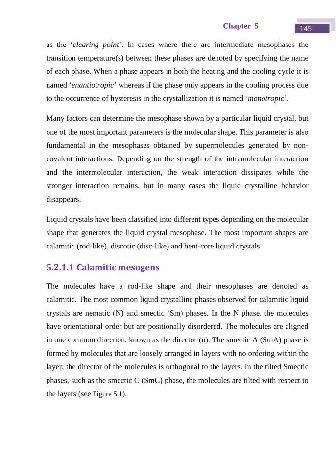
Chapter 5 145
as the ‘clearing point’. In cases where there are intermediate mesophases the
transition temperature(s) between these phases are denoted by specifying the name
of each phase. When a phase appears in both the heating and the cooling cycle it is
named ‘enantiotropic’ whereas if the phase only appears in the cooling process due
to the occurrence of hysteresis in the crystallization it is named ‘monotropic’.
Many factors can determine the mesophase shown by a particular liquid crystal, but
one of the most important parameters is the molecular shape. This parameter is also
fundamental in the mesophases obtained by supermolecules generated by non-
covalent interactions. Depending on the strength of the intramolecular interaction
and the intermolecular interaction, the weak interaction dissipates while the
stronger interaction remains, but in many cases the liquid crystalline behavior
disappears.
Liquid crystals have been classified into different types depending on the molecular
shape that generates the liquid crystal mesophase. The most important shapes are
calamitic (rod-like), discotic (disc-like) and bent-core liquid crystals.
5.2.1.1 Calamitic mesogens
The molecules have a rod-like shape and their mesophases are denoted as
calamitic. The most common liquid crystalline phases observed for calamitic liquid
crystals are nematic (N) and smectic (Sm) phases. In the N phase, the molecules
have orientational order but are positionally disordered. The molecules are aligned
in one common direction, known as the director (n). The smectic A (SmA) phase is
formed by molecules that are loosely arranged in layers with no ordering within the
layer; the director of the molecules is orthogonal to the layers. In the tilted Smectic
phases, such as the smectic C (SmC) phase, the molecules are tilted with respect to
the layers (see Figure 5.1).
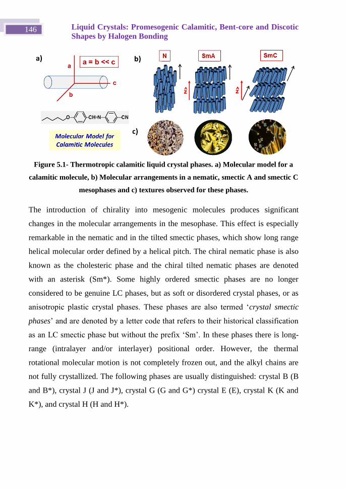
Liquid Crystals: Promesogenic Calamitic, Bent-core and Discotic
Shapes by Halogen Bonding 146
Figure 5.1- Thermotropic calamitic liquid crystal phases. a) Molecular model for a
calamitic molecule, b) Molecular arrangements in a nematic, smectic A and smectic C
mesophases and c) textures observed for these phases.
The introduction of chirality into mesogenic molecules produces significant
changes in the molecular arrangements in the mesophase. This effect is especially
remarkable in the nematic and in the tilted smectic phases, which show long range
helical molecular order defined by a helical pitch. The chiral nematic phase is also
known as the cholesteric phase and the chiral tilted nematic phases are denoted
with an asterisk (Sm*). Some highly ordered smectic phases are no longer
considered to be genuine LC phases, but as soft or disordered crystal phases, or as
anisotropic plastic crystal phases. These phases are also termed ‘crystal smectic
phases’ and are denoted by a letter code that refers to their historical classification
as an LC smectic phase but without the prefix ‘Sm’. In these phases there is long-
range (intralayer and/or interlayer) positional order. However, the thermal
rotational molecular motion is not completely frozen out, and the alkyl chains are
not fully crystallized. The following phases are usually distinguished: crystal B (B
and B*), crystal J (J and J*), crystal G (G and G*) crystal E (E), crystal K (K and
K*), and crystal H (H and H*).
Chapter 5 147
5.2.1.2 Discotic or disc-like mesogens
Discotic mesogens have a disc-like molecular structure, as shown in Figure 5.2.
Figure 5.2- Thermotropic discotic liquid crystal phases. a) Molecular model for a
discotic molecule, b) Molecular arrangements in a discotic nematic and a columnar
nematic, hexagonal and rectangular mesophases and c) textures observed for these
phases.
In the most typical cases, the molecules consist of a more or less rigid flat core
(usually aromatic) surrounded by at least three flexible chains that make up the
‘soft’ region. The rigid core can also be bowl-like, cone-like, or pyramidal (it can
even be a hollow ring). In many cases, individual molecules do not match these
criteria, but they are capable of aggregating into units that do fulfill them.
The least ordered discotic phase is the discotic nematic phase. In this phase, the
molecules move freely with their short axes in parallel to the director. However, the
discotic liquid crystals typically form columnar phases, where the molecules
Liquid Crystals: Promesogenic Calamitic, Bent-core and Discotic
Shapes by Halogen Bonding 148
arrange themselves into columns. Thus, the Columnar Nematic phase does not
show long-range order and the columns are arranged in the same way as the
molecules in a nematic phase. Other columnar phases with long-range order are
classified by their two-dimensional lattices: hexagonal, tetragonal, rectangular, etc.
In the columnar hexagonal phase the columns are ordered in a hexagonal lattice
with six molecules in the vertex of a hexagon and the other in the center. The
columnar rectangular mesophase consists of the stacking of the molecules in
columns, which are in turn packed in a rectangular fashion. These phases could
also be classified as orthogonal and tilted phases depending on whether the short
axis of the disc is parallel or tilted with respect to the director of the phase (see
Figure 5.2).
5.2.1.3 Bent-core mesogens
Bent-core mesogens, which are V-shaped or banana-shaped, have attracted interest
because of their unique properties, such as the ability to form LC mesophases with
super-structural chirality from constituent molecules that are achiral (see Figure
5.3).
The mesophases exhibited by bent-core compounds are similar in some cases to
calamitic ones, i.e., nematic and smectic ordering, but new specific banana types
can be observed in most cases. The occurrence of this mesophase type is strongly
related on the angle between the two arms of the bent-core molecule.
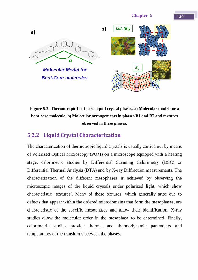
Chapter 5 149
Figure 5.3- Thermotropic bent-core liquid crystal phases. a) Molecular model for a
bent-core molecule, b) Molecular arrangements in phases B1 and B7 and textures
observed in these phases.
5.2.2 Liquid Crystal Characterization
The characterization of thermotropic liquid crystals is usually carried out by means
of Polarized Optical Microscopy (POM) on a microscope equipped with a heating
stage, calorimetric studies by Differential Scanning Calorimetry (DSC) or
Differential Thermal Analysis (DTA) and by X-ray Diffraction measurements. The
characterization of the different mesophases is achieved by observing the
microscopic images of the liquid crystals under polarized light, which show
characteristic ‘textures’. Many of these textures, which generally arise due to
defects that appear within the ordered microdomains that form the mesophases, are
characteristic of the specific mesophases and allow their identification. X-ray
studies allow the molecular order in the mesophase to be determined. Finally,
calorimetric studies provide thermal and thermodynamic parameters and
temperatures of the transitions between the phases.
Molecular Model for Banana
Molecules
Molecular Model for
Bent-Core molecules
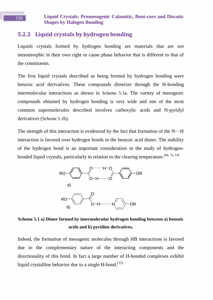
Liquid Crystals: Promesogenic Calamitic, Bent-core and Discotic
Shapes by Halogen Bonding 150
5.2.3 Liquid crystals by hydrogen bonding
Liquids crystals formed by hydrogen bonding are materials that are not
mesomorphic in their own right or cause phase behavior that is different to that of
the constituents.
The first liquid crystals described as being formed by hydrogen bonding were
benzoic acid derivatives. These compounds dimerize through the H-bonding
intermolecular interactions as shown in Scheme 5.1a. The variety of mesogenic
compounds obtained by hydrogen bonding is very wide and one of the most
common supermolecules described involves carboxylic acids and N-pyridyl
derivatives (Scheme 5.1b).
The strength of this interaction is evidenced by the fact that formation of the N···H
interaction is favored over hydrogen bonds in the benzoic acid dimer. The stability
of the hydrogen bond is an important consideration in the study of hydrogen-
bonded liquid crystals, particularly in relation to the clearing temperature.[6b, 7a, 14]
O
O
H
RO
O
O
H
OR
O
O
RON ORH
a)
b)
Scheme 5.1 a) Dimer formed by intermolecular hydrogen bonding between a) benzoic
acids and b) pyridine derivatives.
Indeed, the formation of mesogenic molecules through HB interactions is favored
due to the complementary nature of the interacting components and the
directionality of this bond. In fact a large number of H-bonded complexes exhibit
liquid crystalline behavior due to a single H-bond.[15]
Chapter 5 151
5.2.4 Liquid crystals by halogen bonding
In a similar way to the hydrogen bond, halogen bonds have been observed to
induce mesomorphic behavior in materials that are not themselves mesomorphic.
As occurs with the H-bond, the X-bond also shows high directionality and in order
to obtain liquid crystalline behavior the complementary nature of the complex
plays a fundamental role. Xu, Bruce and Metrangolo took advantage of the
interaction between iodine atoms in perfluorinated benzenes or perfluoralkanes and
basic amine/imine nitrogens to prepare mesomorphic species. These complexes,
which were prepared as dimeric, trimeric or polymeric species, have an elongated
shape that gives rise to calamitic liquid crystals.[13, 16]
Pioneering studies were
carried out on halogen-bonded complexes formed by a pyridine-stilbene derivative
and a perfluoroiodobenzene molecule. These compounds afforded nematic and
smectic A mesophases in all cases. More complex structures were obtained by
preparing trimeric materials.
Different flexible or rigid structures bearing two donor positions, i.e., two iodine
atoms, have been bonded to two stilbene derivatives and in most cases nematic
materials were obtained regardless of the rigidity and linearity of the central unit.
Moreover, if ditopic donors and acceptors are employed, polymeric materials are
obtained that show only a monotropic nematic phase. In these studies the fluorine
atoms improve the electron acceptor ability of both diiodotetrafluorobenzene[16b,
16g] and diiodoperfluoroalkane
[16d] derivatives. In most of the compounds described
by these authors the iodotetrafluorobenzene was used as the XB donor moiety. [16c]
The first reports on the use of alternative XB motifs were published in 2013 by
Mcallister et al.[17]
and Gonzalez et al.[18]
Complexes between N-acceptor
alkoxystilbazole derivatives and halogen molecules exhibited unusually large
mesophase stability and clearing points above 200 °C. Liquid crystallinity was not
observed when I2 was replaced with Br2, and the stilbazolium bromide in which
one of the ethylenic hydrogens was replaced with bromine was formed.[17]
In
Liquid Crystals: Promesogenic Calamitic, Bent-core and Discotic
Shapes by Halogen Bonding 152
another study,[19]
the alkoxystilbazole was replaced with an azopyridine to yield
photoresponsive liquid crystals. In this case, both I2 and Br2 XB donors gave rise to
liquid crystalline complexes. This work demonstrated that not only can bromine-
based XB donors be used in the successful design of supramolecular LCs but, more
surprisingly, dibromine significantly stabilized the mesophase compared to
diiodine.
A different approach to improve the complexation ability is to attach an iodine
atom to an acetylene unit. Indeed, in the early eighties iodoacetylenes were among
the first halogen-bond donors studied in solution in an investigation by Laurence et
al.[20]
Despite the fact that iodoacetylenes behave as strong Lewis acids due to the
I–Csp bond, they have been largely ignored in supramolecular chemistry until
recent applications in the design of conducting organic crystals[21]
and the synthesis
of highly organized conjugated polymers[22]
and molecular rotors.[23]
Chapter 5 153
5.3 Objectives and planning work
5.3.1 Objectives
The main objective of the work described in this chapter was:
To obtain new Li uid Crystals using ‘supermolecules’ formed by means of
halogen bonding interactions.
Secondary objectives:
The design and synthesis of halogen bond donors based on
bis(iodoethynyl)benzene derivatives and halogen bond acceptors based
on basic nitrogen-containing molecules. These compounds could act as
building blocks in the preparation of the supermolecules.
Characterization of the liquid crystal properties and
A study of the structure-activity relationships for the complexes
obtained.
5.3.2 Planned work
In order to achieve the aforementioned aims the use of bis(iodoethynyl)benzene
derivatives as XB-donors can favor liquid crystalline arrangements and give rise to
mesophases that differ from those described to date for XB complexes.
Three of the ive halogen bond doros described in Chapter 2 were selected (see
Scheme 5.2 and Table 5.1), two of which were angular (mBIEB and 1,3,5-TIEB)
and the other one linear (pBIEB). Only the rigid ditopic synthons were selected
because they form part of the molecular core and, in most liquid crystals, the
rigidity and conjugation of this part favors mesomorphism. The shape of these
Liquid Crystals: Promesogenic Calamitic, Bent-core and Discotic
Shapes by Halogen Bonding 154
iodoacetylene central cores could favor the formation of calamitic discotic and
banana liquid crystals.
Scheme 5.2- Different halogen bonding donor mesogen shapes: orange pBIEB, green
mBIEB and blue 1,3,5-TIEB.
Table 0.1 Halogen bond donor mesogens
Name Abbreviated name Electronic
parameter Geometry Rigidity
1,4-bis(iodoethynyl)benzene pBIEB Conjugated
Linear Rigid
1,3-bis(iodoethynyl)benzene mBIEB Conjugated Angular Rigid
1,3,5-tris(iodoethynyl)benzene 1,3,5-TIEB Conjugated Angular Rigid
As basic nitrogen-containing molecules that could act as halogen bond acceptors
two different types of acceptors were assayed: A benzonitrile derivative with an
Chapter 5 155
Nsp nitrogen atom of a nitrile group (BN-10) and seven pyridine derivatives with a
Nsp2 atom 4-(n-decyloxy)pyridine (Py1-10), 4-[2-[4-(n-
tetradecyloxy)phenyl]ethenyl]pyridine (Py2-S-14), 4-pyridinyl-4-(n-
tetradecyloxy)benzoate (Py2-E-14), 4-(2-(pyridin-4-yl)vinyl)phenyl-4-(n-
tetradecyloxy)benzoate (Py3-S-14), 4-(2-(pyridin-4-yl)vinyl)phenyl 4-(n-
octadecyloxy)benzoate (Py3-S-18), 4-pyridinyl-4-[(4-(n-
tetradecyloxy)benzoyl)oxy]benzoate (Py3-E-14), 3,4,5-tris(decyloxy)-N-(pyridin-
4-yl)benzamide (Py2-N-10).
As can be seen in Scheme 5.3, three new series of halogen-bonded complexes based
on linear p-BIEB (series P), bent m-BIEB (series M) and 1,3,5-TIEB (series T,
showing a 3h symmetry) donors have been prepared.
I I
II
pBIEB
mBIEB
OC10H21N
NC10H21O
H2n+1CnO X N
H2n+1CnO
N
O
O X
X-donors X-acceptors
BN-10
Py1-10
Py2-E-14
X: -C=C- Py2-S-14
Py3-E-14
X: -C=C- Py3-S-14
X: -C=C- Py3-S-18
X-bonded complexes
Type P
IINR N
I IN
R
N
RType M
I I
I
1,3,5-TIEB
Y
Y
Y: -H
Y: -H
Y: -OC10H21 Py2-N-10
I
I
N
R
N
R
Type T
IN
R
X: -COO-
X: -COO-
X: -CONH-
N R
Scheme 5.3- Chemical structures of halogen bonding donors and acceptors used in
the promesogenic XB-complexes.
Liquid Crystals: Promesogenic Calamitic, Bent-core and Discotic
Shapes by Halogen Bonding 156
In the series P, M and T trimeric complexes based on one bis-/tris-
(iodoethynyl)benzene and two/three nitrile or pyridine derivatives were prepared.
Depending on the positions of the iodoethynyl substituents in the donor ring,
complexes with three different geometries are expected, i.e., rod-like complexes
(for 1,4-substitution), bent-shaped complexes (for 1,3-substitution) and disc-like
complexes (for 1,3,5-substitution). These complexes would be expected to give
calamitic, bent core and discotic liquid crystalline behavior, respectively.
The new halogen-bonded complexes reported here are identified using a notation
system that indicates first the XB-donor (P, M or T) and XB-acceptor as denoted in
Scheme 5.3. Thus, P-Py3-E-14 is the complex of series P, formed from the XB-
donor P and the XB-acceptor Py3-E-14.
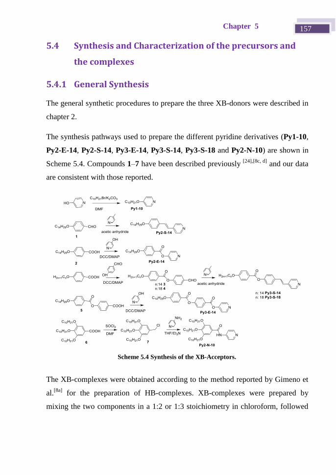
Chapter 5 157
5.4 Synthesis and Characterization of the precursors and
the complexes
5.4.1 General Synthesis
The general synthetic procedures to prepare the three XB-donors were described in
chapter 2.
The synthesis pathways used to prepare the different pyridine derivatives (Py1-10,
Py2-E-14, Py2-S-14, Py3-E-14, Py3-S-14, Py3-S-18 and Py2-N-10) are shown in
Scheme 5.4. Compounds 1–7 have been described previously [24],[8c, d]
and our data
are consistent with those reported.
The XB-complexes were obtained according to the method reported by Gimeno et
al.[8a]
for the preparation of HB-complexes. XB-complexes were prepared by
mixing the two components in a 1:2 or 1:3 stoichiometry in chloroform, followed
Scheme 5.4 Synthesis of the XB-Acceptors.
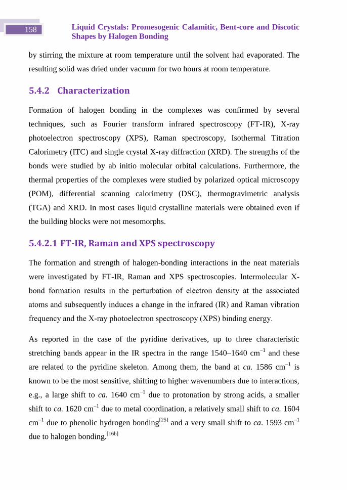
Liquid Crystals: Promesogenic Calamitic, Bent-core and Discotic
Shapes by Halogen Bonding 158
by stirring the mixture at room temperature until the solvent had evaporated. The
resulting solid was dried under vacuum for two hours at room temperature.
5.4.2 Characterization
Formation of halogen bonding in the complexes was confirmed by several
techniques, such as Fourier transform infrared spectroscopy (FT-IR), X-ray
photoelectron spectroscopy (XPS), Raman spectroscopy, Isothermal Titration
Calorimetry (ITC) and single crystal X-ray diffraction (XRD). The strengths of the
bonds were studied by ab initio molecular orbital calculations. Furthermore, the
thermal properties of the complexes were studied by polarized optical microscopy
(POM), differential scanning calorimetry (DSC), thermogravimetric analysis
(TGA) and XRD. In most cases liquid crystalline materials were obtained even if
the building blocks were not mesomorphs.
5.4.2.1 FT-IR, Raman and XPS spectroscopy
The formation and strength of halogen-bonding interactions in the neat materials
were investigated by FT-IR, Raman and XPS spectroscopies. Intermolecular X-
bond formation results in the perturbation of electron density at the associated
atoms and subsequently induces a change in the infrared (IR) and Raman vibration
frequency and the X-ray photoelectron spectroscopy (XPS) binding energy.
As reported in the case of the pyridine derivatives, up to three characteristic
stretching bands appear in the IR spectra in the range 1540–1640 cm–1
and these
are related to the pyridine skeleton. Among them, the band at ca. 1586 cm–1
is
known to be the most sensitive, shifting to higher wavenumbers due to interactions,
e.g., a large shift to ca. 1640 cm–1
due to protonation by strong acids, a smaller
shift to ca. 1620 cm–1
due to metal coordination, a relatively small shift to ca. 1604
cm–1
due to phenolic hydrogen bonding[25]
and a very small shift to ca. 1593 cm–1
due to halogen bonding.[16b]
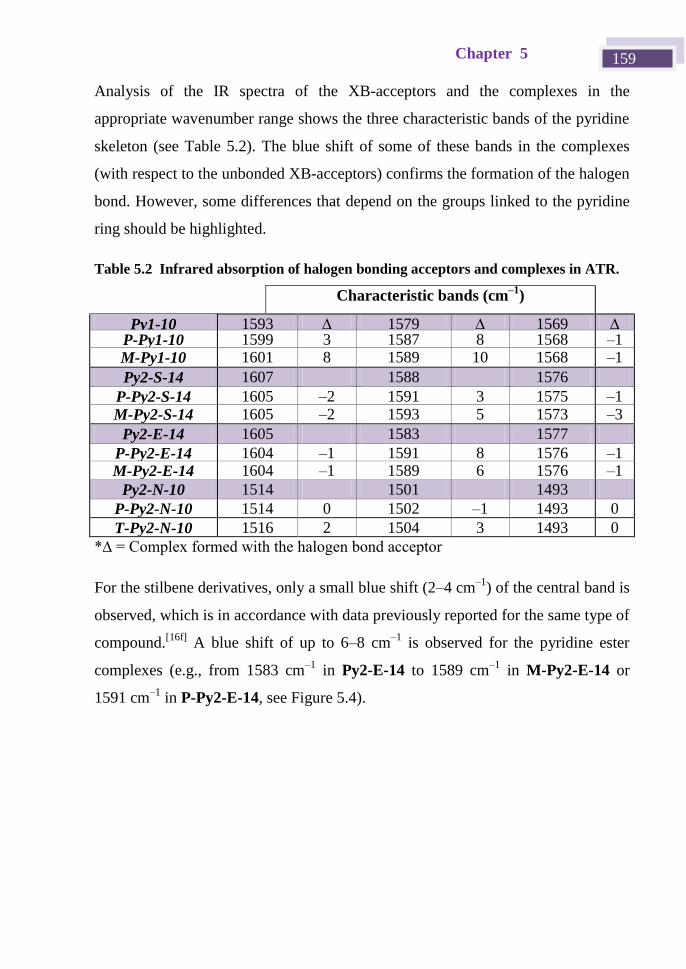
Chapter 5 159
Analysis of the IR spectra of the XB-acceptors and the complexes in the
appropriate wavenumber range shows the three characteristic bands of the pyridine
skeleton (see Table 5.2). The blue shift of some of these bands in the complexes
(with respect to the unbonded XB-acceptors) confirms the formation of the halogen
bond. However, some differences that depend on the groups linked to the pyridine
ring should be highlighted.
Table 5.2 Infrared absorption of halogen bonding acceptors and complexes in ATR.
Characteristic bands (cm–1
)
Py1-10 1593 ∆ 1579 ∆ 1569 ∆ P-Py1-10 1599 3 1587 8 1568 –1 M-Py1-10 1601 8 1589 10 1568 –1
Py2-S-14 1607 1588 1576
P-Py2-S-14 1605 –2 1591 3 1575 –1
M-Py2-S-14 1605 –2 1593 5 1573 –3
Py2-E-14 1605 1583 1577
P-Py2-E-14 1604 –1 1591 8 1576 –1 M-Py2-E-14 1604 –1 1589 6 1576 –1
Py2-N-10 1514 1501 1493
P-Py2-N-10 1514 0 1502 –1 1493 0
T-Py2-N-10 1516 2 1504 3 1493 0
*∆ = Complex formed with the halogen bond acceptor
For the stilbene derivatives, only a small blue shift (2–4 cm–1
) of the central band is
observed, which is in accordance with data previously reported for the same type of
compound.[16f]
A blue shift of up to 6–8 cm–1
is observed for the pyridine ester
complexes (e.g., from 1583 cm–1
in Py2-E-14 to 1589 cm–1
in M-Py2-E-14 or
1591 cm–1
in P-Py2-E-14, see Figure 5.4).
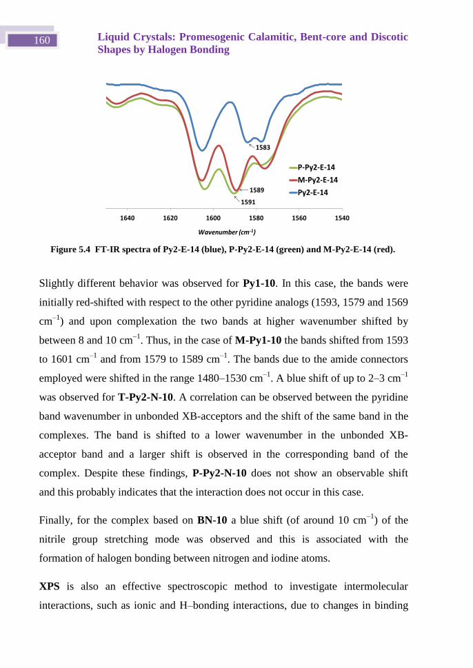
Liquid Crystals: Promesogenic Calamitic, Bent-core and Discotic
Shapes by Halogen Bonding 160
Slightly different behavior was observed for Py1-10. In this case, the bands were
initially red-shifted with respect to the other pyridine analogs (1593, 1579 and 1569
cm–1
) and upon complexation the two bands at higher wavenumber shifted by
between 8 and 10 cm–1
. Thus, in the case of M-Py1-10 the bands shifted from 1593
to 1601 cm–1
and from 1579 to 1589 cm–1
. The bands due to the amide connectors
employed were shifted in the range 1480–1530 cm–1
. A blue shift of up to 2–3 cm–1
was observed for T-Py2-N-10. A correlation can be observed between the pyridine
band wavenumber in unbonded XB-acceptors and the shift of the same band in the
complexes. The band is shifted to a lower wavenumber in the unbonded XB-
acceptor band and a larger shift is observed in the corresponding band of the
complex. Despite these findings, P-Py2-N-10 does not show an observable shift
and this probably indicates that the interaction does not occur in this case.
Finally, for the complex based on BN-10 a blue shift (of around 10 cm–1
) of the
nitrile group stretching mode was observed and this is associated with the
formation of halogen bonding between nitrogen and iodine atoms.
XPS is also an effective spectroscopic method to investigate intermolecular
interactions, such as ionic and H–bonding interactions, due to changes in binding
Figure 5.4 FT-IR spectra of Py2-E-14 (blue), P-Py2-E-14 (green) and M-Py2-E-14 (red).
154015601580160016201640
P-Py2-E-14
M-Py2-E-14
Py2-E-14
Wavenumber (cm-1)
1583
1589
1591
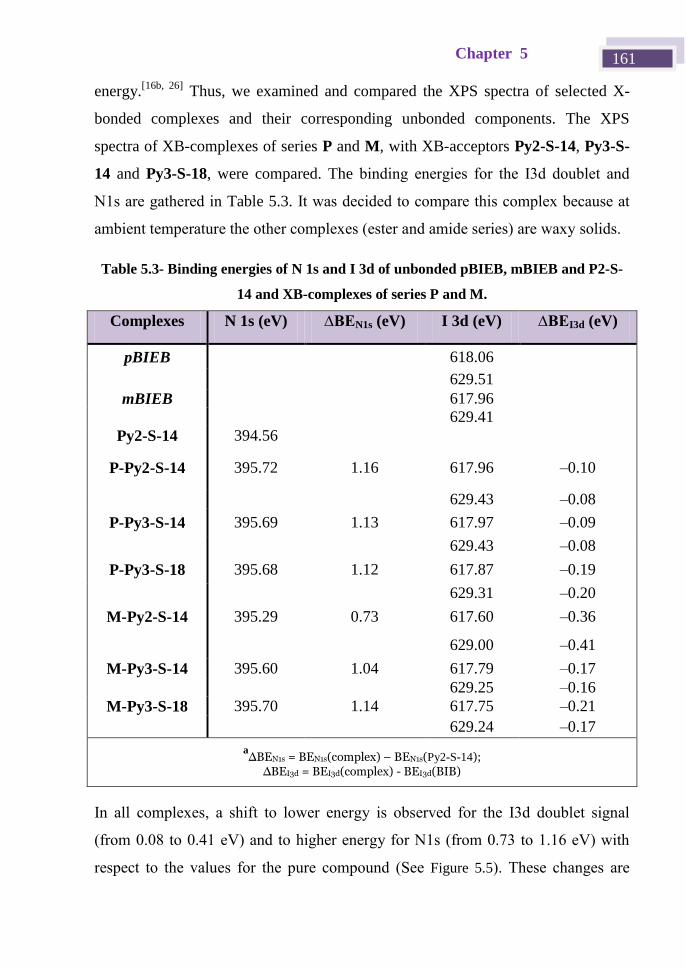
Chapter 5 161
energy.[16b, 26]
Thus, we examined and compared the XPS spectra of selected X-
bonded complexes and their corresponding unbonded components. The XPS
spectra of XB-complexes of series P and M, with XB-acceptors Py2-S-14, Py3-S-
14 and Py3-S-18, were compared. The binding energies for the I3d doublet and
N1s are gathered in Table 5.3. It was decided to compare this complex because at
ambient temperature the other complexes (ester and amide series) are waxy solids.
Table 5.3- Binding energies of N 1s and I 3d of unbonded pBIEB, mBIEB and P2-S-
14 and XB-complexes of series P and M.
Complexes N 1s (eV) ∆BEN1s (eV) I 3d (eV) ∆BEI3d (eV)
pBIEB 618.06
629.51
mBIEB 617.96
629.41
Py2-S-14 394.56
P-Py2-S-14 395.72 1.16 617.96 –0.10
629.43 –0.08
P-Py3-S-14 395.69 1.13 617.97 –0.09
629.43 –0.08
P-Py3-S-18 395.68 1.12 617.87 –0.19
629.31 –0.20
M-Py2-S-14 395.29 0.73 617.60 –0.36
629.00 –0.41
M-Py3-S-14 395.60 1.04 617.79 –0.17
629.25 –0.16
M-Py3-S-18 395.70 1.14 617.75 –0.21
629.24 –0.17
a∆BEN1s = BEN1s(complex) – BEN1s(Py2-S-14); ∆BEI3d = BEI3d(complex) - BEI3d(BIB)
In all complexes, a shift to lower energy is observed for the I3d doublet signal
(from 0.08 to 0.41 eV) and to higher energy for N1s (from 0.73 to 1.16 eV) with
respect to the values for the pure compound (See Figure 5.5). These changes are
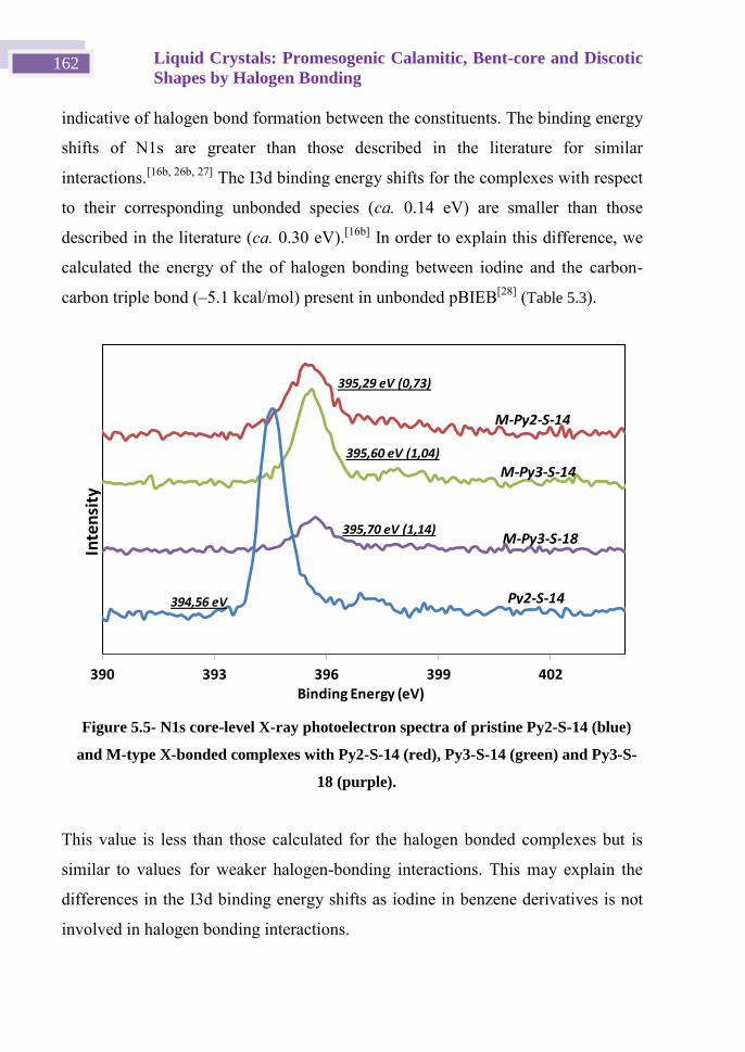
Liquid Crystals: Promesogenic Calamitic, Bent-core and Discotic
Shapes by Halogen Bonding 162
indicative of halogen bond formation between the constituents. The binding energy
shifts of N1s are greater than those described in the literature for similar
interactions.[16b, 26b, 27]
The I3d binding energy shifts for the complexes with respect
to their corresponding unbonded species (ca. 0.14 eV) are smaller than those
described in the literature (ca. 0.30 eV).[16b]
In order to explain this difference, we
calculated the energy of the of halogen bonding between iodine and the carbon-
carbon triple bond (–5.1 kcal/mol) present in unbonded pBIEB[28]
(Table 5.3).
This value is less than those calculated for the halogen bonded complexes but is
similar to values for weaker halogen-bonding interactions. This may explain the
differences in the I3d binding energy shifts as iodine in benzene derivatives is not
involved in halogen bonding interactions.
Figure 5.5- N1s core-level X-ray photoelectron spectra of pristine Py2-S-14 (blue)
and M-type X-bonded complexes with Py2-S-14 (red), Py3-S-14 (green) and Py3-S-
18 (purple).
390 393 396 399 402
Py2-S-14
M-Py3-S-18
M-Py2-S-14
M-Py3-S-14
Inte
nsi
ty
395,29 eV (0,73)
395,60 eV (1,04)
395,70 eV (1,14)
394,56 eV
Binding Energy (eV)
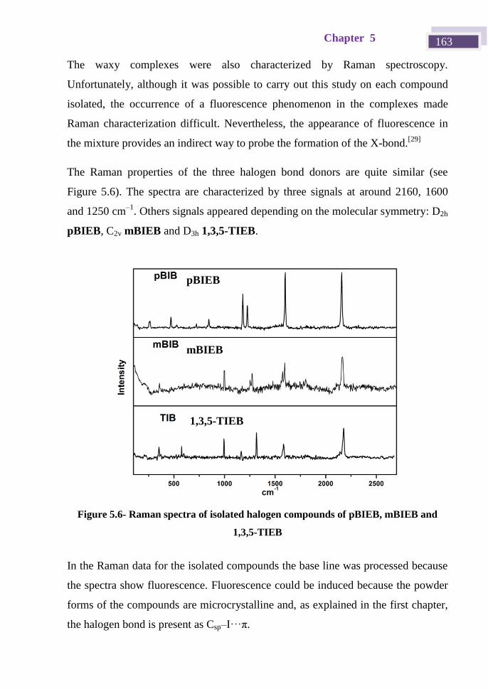
Chapter 5 163
The waxy complexes were also characterized by Raman spectroscopy.
Unfortunately, although it was possible to carry out this study on each compound
isolated, the occurrence of a fluorescence phenomenon in the complexes made
Raman characterization difficult. Nevertheless, the appearance of fluorescence in
the mixture provides an indirect way to probe the formation of the X-bond.[29]
The Raman properties of the three halogen bond donors are quite similar (see
Figure 5.6). The spectra are characterized by three signals at around 2160, 1600
and 1250 cm–1
. Others signals appeared depending on the molecular symmetry: D2h
pBIEB, C2v mBIEB and D3h 1,3,5-TIEB.
In the Raman data for the isolated compounds the base line was processed because
the spectra show fluorescence. Fluorescence could be induced because the powder
forms of the compounds are microcrystalline and, as explained in the first chapter,
the halogen bond is present as Csp–I···π.
Figure 5.6- Raman spectra of isolated halogen compounds of pBIEB, mBIEB and
1,3,5-TIEB
pBIEB
mBIEB
1,3,5-TIEB
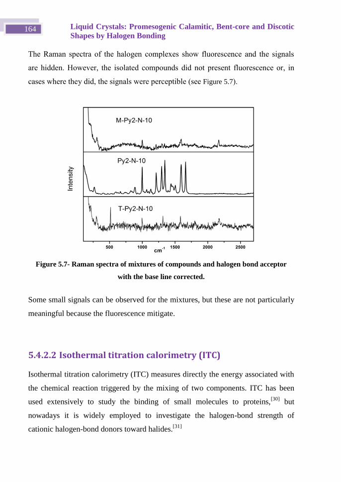
Liquid Crystals: Promesogenic Calamitic, Bent-core and Discotic
Shapes by Halogen Bonding 164
The Raman spectra of the halogen complexes show fluorescence and the signals
are hidden. However, the isolated compounds did not present fluorescence or, in
cases where they did, the signals were perceptible (see Figure 5.7).
Some small signals can be observed for the mixtures, but these are not particularly
meaningful because the fluorescence mitigate.
5.4.2.2 Isothermal titration calorimetry (ITC)
Isothermal titration calorimetry (ITC) measures directly the energy associated with
the chemical reaction triggered by the mixing of two components. ITC has been
used extensively to study the binding of small molecules to proteins,[30]
but
nowadays it is widely employed to investigate the halogen-bond strength of
cationic halogen-bond donors toward halides.[31]
Figure 5.7- Raman spectra of mixtures of compounds and halogen bond acceptor
with the base line corrected.
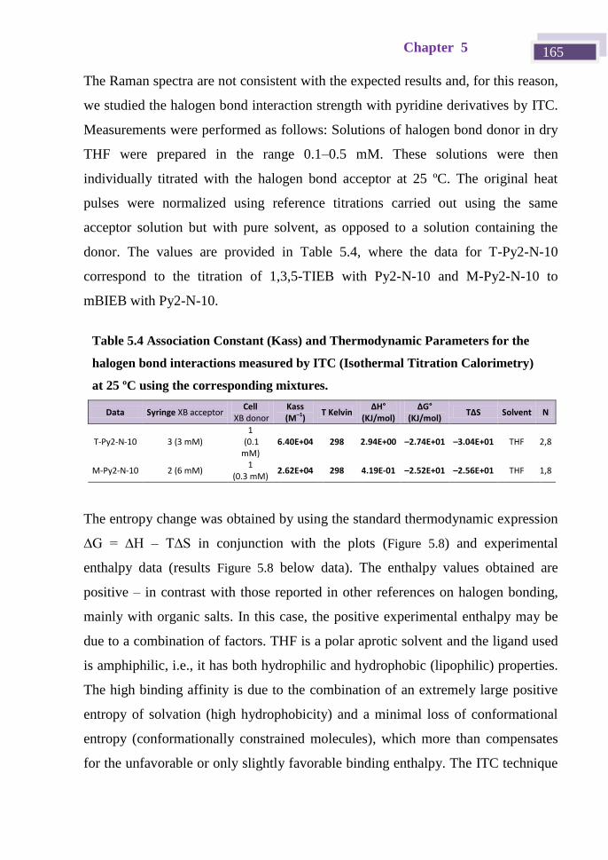
Chapter 5 165
The Raman spectra are not consistent with the expected results and, for this reason,
we studied the halogen bond interaction strength with pyridine derivatives by ITC.
Measurements were performed as follows: Solutions of halogen bond donor in dry
THF were prepared in the range 0.1–0.5 mM. These solutions were then
individually titrated with the halogen bond acceptor at 25 ºC. The original heat
pulses were normalized using reference titrations carried out using the same
acceptor solution but with pure solvent, as opposed to a solution containing the
donor. The values are provided in Table 5.4, where the data for T-Py2-N-10
correspond to the titration of 1,3,5-TIEB with Py2-N-10 and M-Py2-N-10 to
mBIEB with Py2-N-10.
The entropy change was obtained by using the standard thermodynamic expression
∆G = ∆H – T∆S in conjunction with the plots (Figure 5.8) and experimental
enthalpy data (results Figure 5.8 below data). The enthalpy values obtained are
positive – in contrast with those reported in other references on halogen bonding,
mainly with organic salts. In this case, the positive experimental enthalpy may be
due to a combination of factors. THF is a polar aprotic solvent and the ligand used
is amphiphilic, i.e., it has both hydrophilic and hydrophobic (lipophilic) properties.
The high binding affinity is due to the combination of an extremely large positive
entropy of solvation (high hydrophobicity) and a minimal loss of conformational
entropy (conformationally constrained molecules), which more than compensates
for the unfavorable or only slightly favorable binding enthalpy. The ITC technique
Table 5.4 Association Constant (Kass) and Thermodynamic Parameters for the
halogen bond interactions measured by ITC (Isothermal Titration Calorimetry)
at 25 ºC using the corresponding mixtures.
Data Syringe XB acceptor Cell
XB donor Kass (M–1)
T Kelvin ∆H°
(KJ/mol) ∆G°
(KJ/mol) T∆S Solvent N
T-Py2-N-10 3 (3 mM) 1
(0.1 mM)
6.40E+04 298 2.94E+00 –2.74E+01 –3.04E+01 THF 2,8
M-Py2-N-10 2 (6 mM) 1
(0.3 mM) 2.62E+04 298 4.19E-01 –2.52E+01 –2.56E+01 THF 1,8
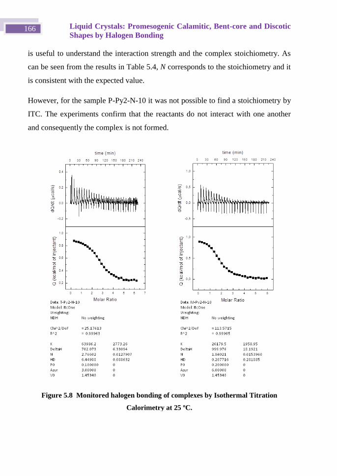
Liquid Crystals: Promesogenic Calamitic, Bent-core and Discotic
Shapes by Halogen Bonding 166
is useful to understand the interaction strength and the complex stoichiometry. As
can be seen from the results in Table 5.4, N corresponds to the stoichiometry and it
is consistent with the expected value.
However, for the sample P-Py2-N-10 it was not possible to find a stoichiometry by
ITC. The experiments confirm that the reactants do not interact with one another
and consequently the complex is not formed.
Figure 5.8 Monitored halogen bonding of complexes by Isothermal Titration
Calorimetry at 25 ºC.
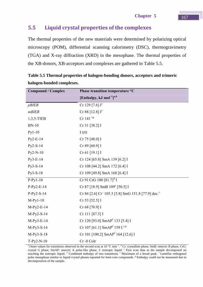
Chapter 5 167
5.5 Liquid crystal properties of the complexes
The thermal properties of the new materials were determined by polarizing optical
microscopy (POM), differential scanning calorimetry (DSC), thermogravimetry
(TGA) and X-ray diffraction (XRD) in the mesophase. The thermal properties of
the XB-donors, XB-acceptors and complexes are gathered in Table 5.5.
Table 5.5 Thermal properties of halogen-bonding donors, acceptors and trimeric
halogen-bonded complexes.
Compound / Complex Phase transition temperature °C
[Enthalpy, kJ mol–1
]a,b
pBIEB Cr 129 [7.6] Ic
mBIEB Cr 88 [12.8] Ic
1,3,5-TIEB Cr 141 cg
BN-10 Cr 31 [38.2] I
Py1-10 I (rt)
Py2-E-14 Cr 75 [48.0] I
Py2-S-14 Cr 89 [60.9] I
Py2-N-10 Cr 61 [19.1] I
Py3-E-14 Cr 124 [65.8] SmA 139 [6.2] I
Py3-S-14 Cr 108 [44.2] SmA 172 [6.4] I
Py3-S-18 Cr 109 [49.8] SmA 168 [6.4] I
P-Py1-10 Cr 91 CrG 100 [81.7]
d I
P-Py2-E-14 Cr 87 [18.9] SmB 109e [50.5] I
P-Py2-S-14 Cr 84 [2.6] Cr´ 105.3 [3.8] SmG 151.8 [77.9] dec.c
M-Py1-10 Cr 53 [52.5] I
M-Py2-E-14 Cr 68 [70.9] I
M-Py2-S-14 Cr 111 [87.5] I
M-Py3-E-14 Cr 120 [93.0] SmAPf 133 [5.4] I
M-Py3-S-14 Cr 107 [61.1] SmAPf 159 I.
c,g
M-Py3-S-18 Cr 101 [100.2] SmAPf 164 [12.6] I
T-Py2-N-10 Cr -8 Colr a Onset values for transitions observed in the second scan at 10 °C min–1. b Cr: crystalline phase, SmB: smectic B phase, CrG:
crystal G phase, SmAP: smectic A polar-like phase, I: isotropic liquid. c First scan data as the sample decomposed on
reaching the isotropic liquid. d Combined enthalpy of two transitions. e Maximum of a broad peak. f Lamellar orthogonal polar mesophase similar to liquid crystal phases reported for bent-core compounds. g Enthalpy could not be measured due to
decomposition of the sample.
Liquid Crystals: Promesogenic Calamitic, Bent-core and Discotic
Shapes by Halogen Bonding 168
All of the XB-complexes were first studied by POM. The solid samples should
melt cleanly without the appearance of biphasic regions, which would indicate the
presence of nonstoichiometric complexes. Unfortunately, all attempts to prepare
suitable samples of complexes P-BN-10 and P-Py2-N-10 were unsuccessful and
only inhomogeneous samples were obtained.
All of the building blocks – both XB-donors and XB-acceptors – are either liquids
or crystalline solids, except for the pyridine derivatives containing three aromatic
rings, which show a SmA mesophase. It can be seen that in all cases, i.e., the
amide, ester and stilbene derivatives, at least three aromatic rings are needed to
induce mesomorphism. The complex formed with promesogenic units bearing only
two aromatic rings are not liquid crystals. On the other hand, if we compare three-
ring systems, the stilbene derivatives promote stronger stabilization of the SmA
mesophase in comparison with the ester or amide analogs. This may be due to the
stilbene derivatives preferentially adopting a flat conformation, in contrast to the
other derivatives.
Regarding the complexes, the mesomorphic behavior depends strongly on the type
of XB-donor used. Complexes in series P preferentially showed calamitic
mesophases. In this case, mesomorphism is already favored by short acceptors,
either with one or two aromatic rings. All of the complexes with longer acceptors
(three aromatic rings) were liquid crystalline materials that decomposed before
reaching the isotropic liquid. However, for Type M materials, mesomorphism was
only observed for the longest XB-acceptors, i.e. those bearing at least seven
aromatic rings in the complex. For series T only amides were employed to form
complexes, because it was expected that π-stacking would be favored. Some
representative DSC curves are gathered in Figure 5.9.
Chapter 5 169
In the next section a detailed explanation of the mesogenic behavior of the different
series of complexes is provided.
Figure 5.9- DSC Thermograms of first heating scans at 10 ºC/min for (a) M, Py3-
S-14 and M-Py3-S-14 and (b) M, Py3-S-18 and M-Py3-S-18.
Liquid Crystals: Promesogenic Calamitic, Bent-core and Discotic
Shapes by Halogen Bonding 170
5.5.1 Series P (rod-like structures)
The three complexes of this series are mesomorphs. Indeed, complexes P-Py1-10,
P-Py2-E-14 and P-Py2-S-14, with 3 or 5 aromatic rings, showed highly ordered
mesophases. To date, most of the liquid crystals based on halogen bonds have only
shown low order calamitic mesophases such as nematic and smectic A.[16b, 16g]
The mesophase of the shortest compound, P-Py1-10, was assigned as crystal G as
it showed the characteristic texture of this phase (dendritic growth of elongated
platelets that are rectangular in shape) (Figure 5.10 (left)).[28]
This phase is highly
viscous and showed an X-ray pattern with several sharp peaks that are
characteristic of the high order of this phase. The same type of mesophase was
assigned for complex P-Py2-S-14 due to the similar textures observed by POM. In
this case, a rapid cooling process from the isotropic liquid was carried out in order
to minimize decomposition of the sample.
In contrast to the above, the other complex (P-Py2-E-14) showed a different
mosaic texture, which in this case is assigned to a SmB mesophase (Figure 5.10
(right)).[32]
The crystalline nature of this phase was also confirmed by XRD, which
showed two sharp reflections (Figure 5.11) and the absence of a diffuse halo.
Figure 5.10- Optical textures of: (left) CrG phase of P-Py1-10 at 86 ºC, (right)
SmB phase of P-Py2-E-14 at 108 ºC.
v
Chapter 5 171
Both SmB and crystal G are highly ordered phases that are more ordered than the
SmA mesophase found in the XB-acceptors. In particular, in the SmB phase the
molecules exhibit hexagonal ordering within the orthogonal layers. In contrast, the
crystal G phase is one of the so-called tilted soft crystal phases. This phase is even
more ordered and shows long-range positional order in three dimensions, with the
molecules tilted within the layers. Such high order arrangements are quite common
in rod-like hydrogen-bonded complexes.[33]
Furthermore, it has been claimed that
these compounds have attractive optical applications,[34]
for example as hosts in
highly ordered host-guest systems for polarizers.
5.5.2 Series M (bent-shaped structures)
Seven complexes bearing mBIEB as the XB-donor were prepared and
characterized. However, only the longest compounds, which contain seven
aromatic rings, afforded mesomorphic materials. The other materials, with either
three (M-Py1-10) or five (M-Py2-E-14 and M-Py2-S-14) aromatic rings, did not
show any liquid crystalline phases. Regarding seven-ring systems, those based on
stilbene receptors (M-Py3-S-14 and M-Py3-S-18) showed wide mesophase ranges
at relatively high temperatures. Even in cases where the textures observed in the
heating process were not clear, XRD experiments allowed us to assign the type of
Figure 5.11-. X-ray diffractogram of the XB complex P-Py2-E-14 in the SmB phase
at 95 ºC.
Liquid Crystals: Promesogenic Calamitic, Bent-core and Discotic
Shapes by Halogen Bonding 172
mesophase. Up to two sharp reflections in the small-angle region and a diffuse halo
in the wide-angle region were detected, thus confirming the mesomorphic nature of
the phase. (See Figure 4.12)
The presence of two or more reflections is not common in classical SmA phases
but is usually found in XRD diffractograms of the SmAP phase, which was
recently found in bent-core liquid crystals (see Figure 5.12). Moreover, layer
spacings of 79.2 Å and 89.6 Å were measured for M-Py3-S-14 and M-Py3-S-18,
respectively. These values are in the range of the molecular lengths calculated
theoretically using Chemsketch (84 and 92 Å) for the trimeric complexes in all-
trans conformations, indicating an orthogonal arrangement of the molecules within
the mesophase and hence an orthogonal mesophase. In addition, these values are
much higher than the layer spacings measured for the corresponding X-B acceptors
Py3-S-14 and Py-3-S-18 in the SmA phase (38.5 Å and 44.6 Å, respectively)
(Figure 5.13).
Figure 5.12- X-ray diffractograms of the XB complex M-Py3-S-18 in the SmAP-like
mesophase (a) at 120 ºC and (b) at room temperature after rapid cooling from the
mesophase temperature. Two sharp reflections in the low angle region are observed.
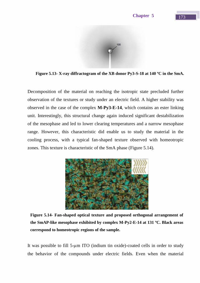
Chapter 5 173
Decomposition of the material on reaching the isotropic state precluded further
observation of the textures or study under an electric field. A higher stability was
observed in the case of the complex M-Py3-E-14, which contains an ester linking
unit. Interestingly, this structural change again induced significant destabilization
of the mesophase and led to lower clearing temperatures and a narrow mesophase
range. However, this characteristic did enable us to study the material in the
cooling process, with a typical fan-shaped texture observed with homeotropic
zones. This texture is characteristic of the SmA phase (Figure 5.14).
It was possible to fill 5-m ITO (indium tin oxide)-coated cells in order to study
the behavior of the compounds under electric fields. Even when the material
Figure 5.14- Fan-shaped optical texture and proposed orthogonal arrangement of
the SmAP-like mesophase exhibited by complex M-Py2-E-14 at 131 ºC. Black areas
correspond to homeotropic regions of the sample.
Figure 5.13- X-ray diffractogram of the XB donor Py3-S-18 at 140 ºC in the SmA.
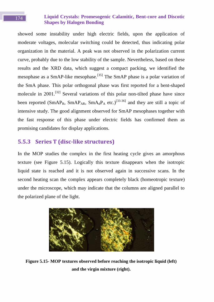
Liquid Crystals: Promesogenic Calamitic, Bent-core and Discotic
Shapes by Halogen Bonding 174
showed some instability under high electric fields, upon the application of
moderate voltages, molecular switching could be detected, thus indicating polar
organization in the material. A peak was not observed in the polarization current
curve, probably due to the low stability of the sample. Nevertheless, based on these
results and the XRD data, which suggest a compact packing, we identified the
mesophase as a SmAP-like mesophase.[35]
The SmAP phase is a polar variation of
the SmA phase. This polar orthogonal phase was first reported for a bent-shaped
molecule in 2001.[32]
Several variations of this polar non-tilted phase have since
been reported (SmAPR, SmAPAR, SmAdPA etc.)[33-36]
and they are still a topic of
intensive study. The good alignment observed for SmAP mesophases together with
the fast response of this phase under electric fields has confirmed them as
promising candidates for display applications.
5.5.3 Series T (disc-like structures)
In the MOP studies the complex in the first heating cycle gives an amorphous
texture (see Figure 5.15). Logically this texture disappears when the isotropic
liquid state is reached and it is not observed again in successive scans. In the
second heating scan the complex appears completely black (homeotropic texture)
under the microscope, which may indicate that the columns are aligned parallel to
the polarized plane of the light.
Figure 5.15- MOP textures observed before reaching the isotropic liquid (left)
and the virgin mixture (right).
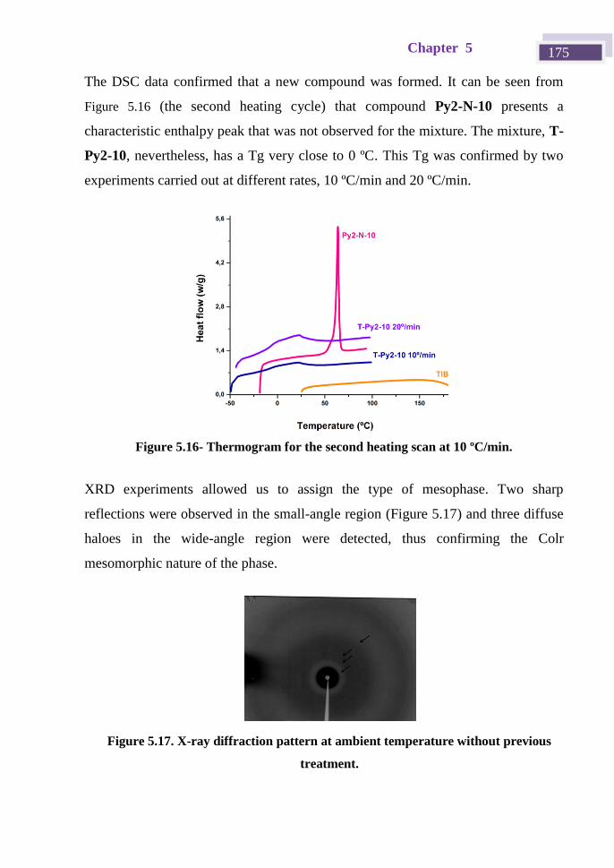
Chapter 5 175
The DSC data confirmed that a new compound was formed. It can be seen from
Figure 5.16 (the second heating cycle) that compound Py2-N-10 presents a
characteristic enthalpy peak that was not observed for the mixture. The mixture, T-
Py2-10, nevertheless, has a Tg very close to 0 ºC. This Tg was confirmed by two
experiments carried out at different rates, 10 ºC/min and 20 ºC/min.
XRD experiments allowed us to assign the type of mesophase. Two sharp
reflections were observed in the small-angle region (Figure 5.17) and three diffuse
haloes in the wide-angle region were detected, thus confirming the Colr
mesomorphic nature of the phase.
Figure 5.17. X-ray diffraction pattern at ambient temperature without previous
treatment.
Figure 5.16- Thermogram for the second heating scan at 10 ºC/min.
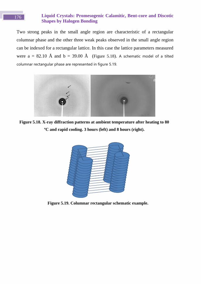
Liquid Crystals: Promesogenic Calamitic, Bent-core and Discotic
Shapes by Halogen Bonding 176
Two strong peaks in the small angle region are characteristic of a rectangular
columnar phase and the other three weak peaks observed in the small angle region
can be indexed for a rectangular lattice. In this case the lattice parameters measured
were a = 82.10 Å and b = 39.00 Å (Figure 5.18). A schematic model of a tilted
columnar rectangular phase are represented in figure 5.19.
Figure 5.19. Columnar rectangular schematic example.
Figure 5.18. X-ray diffraction patterns at ambient temperature after heating to 80
ºC and rapid cooling. 3 hours (left) and 8 hours (right).
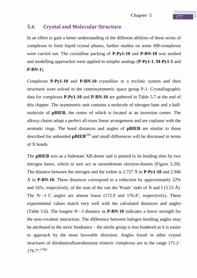
Chapter 5 177
5.6 Crystal and Molecular Structure
In an effort to gain a better understanding of the different abilities of these series of
complexes to form liquid crystal phases, further studies on some HB-complexes
were carried out. The crystalline packing of P-Py1-10 and P-BN-10 was studied
and modelling approaches were applied to simpler analogs (P-Py1-1, M-Py1-1 and
P-BN-1).
Complexes P-Py1-10 and P-BN-10 crystallize in a triclinic system and their
structures were solved in the centrosymmetric space group P-1. Crystallographic
data for complexes P-Py1-10 and P-BN-10 are gathered in Table 5.7 at the end of
this chapter. The asymmetric unit contains a molecule of nitrogen base and a half-
molecule of pBIEB, the center of which is located at an inversion center. The
alkoxy chains adopt a perfect all-trans linear arrangement and are coplanar with the
aromatic rings. The bond distances and angles of pBIEB are similar to those
described for unbonded pBIEB[28]
and small differences will be discussed in terms
of X bonds.
The pBIEB acts as a bidentate XB-donor and is pinned to its binding sites by two
nitrogen bases, which in turn act as monodentate electron-donors (Figure 5.20).
The distance between the nitrogen and the iodine is 2.757 Å in P-Py1-10 and 2.946
Å in P-BN-10. These distances correspond to a reduction by approximately 22%
and 16%, respectively, of the sum of the van der aals’ radii of N and I (3.53 Å).
The N···I–C angles are almost linear (172.9 and 176.4°, respectively). These
experimental values match very well with the calculated distances and angles
(Table 5.6). The longest N···I distance in P-BN-10 indicates a lower strength for
the non-covalent interaction. The difference between halogen bonding angles may
be attributed to the steric hindrance – the nitrile group is less hindered as it is easier
to approach by the most favorable direction. Angles found in other crystal
structures of diiodotetrafluorobenzene trimeric complexes are in the range 171.2–
176.7°.[16g]
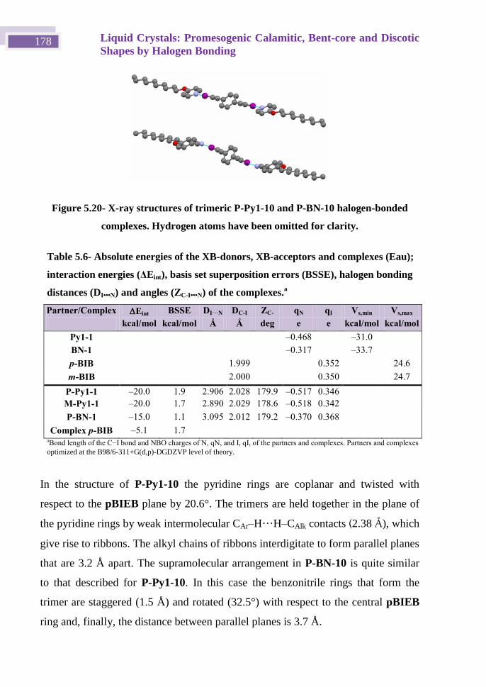
Liquid Crystals: Promesogenic Calamitic, Bent-core and Discotic
Shapes by Halogen Bonding 178
Figure 5.20- X-ray structures of trimeric P-Py1-10 and P-BN-10 halogen-bonded
complexes. Hydrogen atoms have been omitted for clarity.
In the structure of P-Py1-10 the pyridine rings are coplanar and twisted with
respect to the pBIEB plane by 20.6°. The trimers are held together in the plane of
the pyridine rings by weak intermolecular CAr–H···H–CAlk contacts (2.38 Å), which
give rise to ribbons. The alkyl chains of ribbons interdigitate to form parallel planes
that are 3.2 Å apart. The supramolecular arrangement in P-BN-10 is quite similar
to that described for P-Py1-10. In this case the benzonitrile rings that form the
trimer are staggered (1.5 Å) and rotated (32.5°) with respect to the central pBIEB
ring and, finally, the distance between parallel planes is 3.7 Å.
Table 5.6- Absolute energies of the XB-donors, XB-acceptors and complexes (Eau);
interaction energies (ΔEint), basis set superposition errors (BSSE), halogen bonding
distances (DI•••N) and angles (ZC-I•••N) of the complexes.a
Partner/Complex Eint BSSE DI···N DC-I ZC-
I···N
qN qI Vs,min Vs,max
kcal/mol kcal/mol Å Å deg e e kcal/mol kcal/mol
Py1-1 –0.468 –31.0
BN-1 –0.317 –33.7
p-BIB 1.999 0.352 24.6
m-BIB 2.000 0.350 24.7
P-Py1-1 –20.0 1.9 2.906 2.028 179.9 –0.517 0.346
M-Py1-1 –20.0 1.7 2.890 2.029 178.6 –0.518 0.342
P-BN-1 –15.0 1.1 3.095 2.012 179.2 –0.370 0.368
Complex p-BIB –5.1 1.7 aBond length of the C−I bond and NBO charges of N, N, and I, I, of the partners and complexes. Partners and complexes
optimized at the B98/6-311+G(d,p)-DGDZVP level of theory.
Chapter 5 179
These data, and in particular the longer N···I distance for P-BN-10 (2.946(1) Å
versus 2.757(1) Å for P-Py1-10, showing weaker non-covalent interactions in the
former) support the differences between these two types of complexes in terms of
their mesomorphic properties.
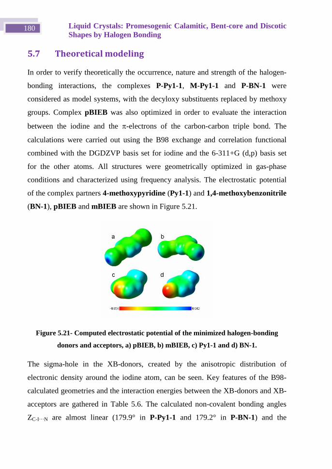
Liquid Crystals: Promesogenic Calamitic, Bent-core and Discotic
Shapes by Halogen Bonding 180
5.7 Theoretical modeling
In order to verify theoretically the occurrence, nature and strength of the halogen-
bonding interactions, the complexes P-Py1-1, M-Py1-1 and P-BN-1 were
considered as model systems, with the decyloxy substituents replaced by methoxy
groups. Complex pBIEB was also optimized in order to evaluate the interaction
between the iodine and the -electrons of the carbon-carbon triple bond. The
calculations were carried out using the B98 exchange and correlation functional
combined with the DGDZVP basis set for iodine and the 6-311+G (d,p) basis set
for the other atoms. All structures were geometrically optimized in gas-phase
conditions and characterized using frequency analysis. The electrostatic potential
of the complex partners 4-methoxypyridine (Py1-1) and 1,4-methoxybenzonitrile
(BN-1), pBIEB and mBIEB are shown in Figure 5.21.
Figure 5.21- Computed electrostatic potential of the minimized halogen-bonding
donors and acceptors, a) pBIEB, b) mBIEB, c) Py1-1 and d) BN-1.
The sigma-hole in the XB-donors, created by the anisotropic distribution of
electronic density around the iodine atom, can be seen. Key features of the B98-
calculated geometries and the interaction energies between the XB-donors and XB-
acceptors are gathered in Table 5.6. The calculated non-covalent bonding angles
ZC-I···N are almost linear (179.9° in P-Py1-1 and 179.2° in P-BN-1) and the
Chapter 5 181
halogen-bonding distances DI···N (2.906 Å in P-Py1-1 and 3.095 Å in P-BN-1) are
appreciably shorter than the sum of the van der Waals radii (3.53 Å). These data
show good agreement with angles (172.95° in P-Py1-10 and 176.45° in P-BN-10)
and halogen-bonding distances (2.757 Å in P-Py1-10 and 2.946 Å in P-BN-10)
determined in the crystal structures of P-Py1-10 and P-BN-10. The C–I bond
distances increase upon halogen-bonding complex formation.
The interaction energies (ΔEint) were determined using the equation:
partnercomplexint EEE
with values of –20.0 kcal/mol obtained for complexes P-Py1-1, M-Py1-1 and –
15.0 kcal/mol for the P-BN-1. These values are higher than those calculated for
some analogous pyridine-halotetrafluorobenzene complexes[16b, 27, 37]
and are in the
typical range for medium-to-strong hydrogen bonding.[38]
Furthermore, these
energies depend on the halogen-bonding acceptor, with pyridine complexes
showing higher interaction energies than the nitrile complex. In addition, the I···N
distance of the trimers P-Py1-1 and M-Py1-1 is shorter than the analogous distance
in the complex P-BN-1. This fact is consistent with the nitrogen of the pyridine
derivative enhancing the halogen bonding appreciably.
The presence of a sufficiently strong positive region on the outer surface of an
atom is an indication that an attractive interaction with a nucleophile is likely,
although this is not the only factor.[39]
The values of the most positive electrostatic
potentials on the molecular surfaces (Vs,max) for pBIEB and mBIEB (24.6
kcal/mol) are similar to that of 1,4-diiodotetrafluorobenzene (23.2 kcal/mol).
Despite this, the interaction energies calculated for the complexes P-Py1-1 and M-
Py1-1 (ΔEint = –10 kcal/mol) are higher than those described for 1,4-
diiodotetrafluorobenzene with pyridine derivatives (ΔEint = –5.59 kcal/mol).[37]
This may be due to combination of a higher Vs,max and the lower steric hindrance of
bis(iodoethynyl)benzene derivatives.
Liquid Crystals: Promesogenic Calamitic, Bent-core and Discotic
Shapes by Halogen Bonding 182
5.8 Conclusions
Iodoethynylbenzene derivatives have proven to be good halogen-bonding donors.
The binding of an iodine atom to an sp hybridized carbon atom generates a deep -
hole in the iodine atom and this, combined with the low steric hindrance of this
system, leads to the formation of strong non-covalent interactions with pyridine
derivatives (ΔEint = –10 kcal/mol) and somewhat weaker interactions with
benzonitriles (ΔEint = –7.5 kcal/mol).
The linear pBIEB forms halogen-bonding complexes with pyridine-based
acceptors bearing one or two aromatic rings to give complexes that show ordered
calamitic phases (SmB and CrG) over wide temperature ranges. On the other hand,
the bent mBIEB forms halogen-bonding complexes with pyridine derivatives that
contain three aromatic rings. Furthermore, disc-like 1,3,5-TIEB forms halogen-
bonding complexes with pyridine derivatives with amines as connectors. These
complexes show liquid crystal phases that are characteristic of bent-core
compounds and they respond under electric fields. XRD, ITC, Raman and
modeling studies support the experimental results and also explain the weaker
interactions of these iodine donors with a benzonitrile-based acceptor. It was found
experimentally that this weaker interaction prevents the formation of homogeneous
halogen-bonding complexes on melting.
Chapter 5 183
5.9 Eperimental Section
All commercial reagents were used as purchased. FT-IR spectra were recorded on a
Bruker Vertex spectrophotometer. 1H and
13C NMR spectra were recorded on a
Bruker Avance 400 spectrometer (9.4 T, 400.13 MHz for 1H, 100.62 MHz for
13C)
or a Bruker Avance 300 spectrometer (9.4 T, 400.13 MHz for 1H, 100.62 MHz for
13C). The mesophase identification was based on microscopic examination of the
textures formed by samples between two glass slides. NIKON and OLYMPUS
BH-2 polarizing microscopes equipped with a LINKAM THMS600 hot stage were
used. The temperatures and enthalpies of the phase transitions were determined by
calorimetric measurements performed with DSC TA Instruments Q-20 and Q-2000
systems. Thermogravimetric analysis (TGA) was performed using a TA Q5000IR
instrument at a heating rate of 10 ºC /min under a nitrogen atmosphere. The X-ray
investigations on non-oriented samples were carried out in Lindemann capillary
tubes (diameter: 0.9 or 1 mm) using a PINHOLE (ANTON–PAAR) film camera.
The XPS instrument was a Kratos Aris Ultra DLD. The X-ray source was run at 12
kV and 10 mA. All core-level spectra were referenced to the C 1s neutral carbon
peak at a binding energy of 285.0 eV in order to compensate for surface charge
effects. The pressure in the analysis chamber was maintained under ultrahigh
vacuum below 10–9
mbar.
5.9.1 Synthesis
4-(Decyloxy)benzonitrile BN-10. 4-Dihydroxybenzaldehyde (7.00 g, 52.63 mmol)
and anhydrous potassium carbonate (21 g, 157.89 mmol) were stirred in dry DMF
(95 mL). The mixture was heated to 100 ºC under an inert atmosphere and then 1-
bromodecane (14 g, 63.20 mmol) was added slowly. The mixture was stirred at 80
ºC for 12 h. The reaction mixture was poured into ice-water and extracted with
CH2Cl2. The combined extracts were washed with water and brine, dried over
anhyd Na2SO4 and concentrated. The crude product was recrystallised from ethanol
to give the pure product. Yield 5.8 g (80%).
Liquid Crystals: Promesogenic Calamitic, Bent-core and Discotic
Shapes by Halogen Bonding 184
1H NMR (300 MHz, CDCl3) δ (ppm): . (d, 2H, J = Hz, Ar), . 3 (d, 2H, J =
Hz, Ar), 3.99 (t, 2H, J = 6 Hz, 1 × OCH2), 1.24–1.81 (m, 16H, 8 × CH2), 0.88 (t,
3H, J = 6 Hz, 1 × CH3); 13C NMR (CDCl3, 100 MHz): 162.67, 134.16, 119.55,
115.37, 103.82, 68.63, 32.08, 29.73, 29.51, 29.18, 26.13, 22.88, 14.31;. MS (ESI+-
MS) m/z: 260.2 [M + H]+.
4-(Decyloxy)pyridine (Py1-10). 4-Hydroxypyridine (5.00 g, 52.63 mmol) and
anhydrous potassium carbonate (21 g, 157.89 mmol) were stirred in dry DMF (95
mL). The mixture was heated to 100 ºC under an inert atmosphere and then 1-
bromodecane (14 g, 63.20 mmol) was added slowly. The mixture was stirred at 100
ºC for 6 h. The mixture was allowed to cool to room temperature and extracted
with a mixture of hexane/ethyl acetate (1:1). The organic solution was washed with
NaOH (10%) and brine and then dried over MgSO4, filtered and the solvent was
evaporated. The resulting product was purified by column chromatography using
hexane/dichloromethane (3:2) as eluent to give red oil. Yield 3.52 g (70%).
1H NM (300 MHz, CDCl3) δ (ppm): 0.83–0.94 (t, J = 6.7 Hz, 3H), 1.18–1.39 (s,
8H), 1.39–1.52 (m, 2H), 1.61–1.71 (s, 1H), 1.73–1.87 (p, J = 6.6 Hz, 2H), 3.95–
4.06 (t, J = 6.5 Hz, 2H), 6.76– .82 (d, J = 4. Hz). 13C NM (101 MHz, CDCl3) δ
(ppm): 14.03, 22.61, 25.86, 28.82, 29.25, 29.47, 31.82, 67.78, 76.84, 110.17,
150.89, 164.98. MS (ESI+-MS) m/z: 236 [M + H]
+
4-[2-[4-(Tetradecyloxy)phenyl]ethenyl]pyridine (Py2-S-14). A mixture of
compound 1 (1.35 g, 3.1 mmol) and picoline (0.287 g, 3.1 mmol) was heated under
reflux in acetic anhydride for 48 h. The reaction mixture was cooled down to rt and
the solid was filtered and recrystallized from ethyl acetate to yield a yellowish
solid. Yield 3 g (30%).
1H NM (400 MHz, CDCl3) δ (ppm): 0.88 (t, J = .0 Hz, 3H) 1.2 –1.45 (m,
22H), 1.80 (m, 2H), 3.98 (t, J = 6.0 Hz, 2H), 6. 86 (d, J = 16 Hz, 1H), 6.90 (d, J = 8
Hz, 2H), 7.24 (d, J = 16.0 Hz, 1H) 7.32 (d, J = 8.0 Hz, 2H), 7.46 (d, J = 8.0 Hz,
Chapter 5 185
2H), 8.53 (d, J = 8.0 Hz, 2H). 13C NM (100 MHz, CDCl3) δ (ppm): 14.1, 22. ,
26.0, 29.2, 29.3, 29.4, 29.5, 29.6, 29.7, 29.8, 31.9, 68.1, 114.8, 120.6, 123.5, 128.4,
128.7, 132.9, 145.1, 150.0, 159.8.
4-Pyridinyl-4-(tetradecyloxy)benzoate (Py2-E-14). Compound 2 (0.50 g, 1.4
mmol), 4-hydroxypyridine (0.134 g, 1.4 mmol) and DMAP (0.02 g, 0.14 mmol)
were dissolved in dry dichloromethane (50 mL) in an ice bath. The reaction
mixture was stirred under an argon atmosphere for 30 min. DCC (0.32 g, 1.5
mmol) was added and the mixture was stirred at room temperature for 24 h. The
solid was filtered off and the solvent was evaporated. The crude product was
purified by flash chromatography using dichloromethane as eluent to yield a white
solid. Yield 0.25 g (43%).
1H NMR (300 MHz, CDCl3) δ (ppm): 0.8 (t, J = .0 Hz, 3H) 1.2 –1.49 (m, 22H),
1.84 (m, 2H), 4.05 (t, J = 6.0 Hz, 2H), 6.99 (d, J = 8.9 Hz, 2H), 7.26 (d, J = 5.1 Hz,
2H) 8.13 (d, J = 9.0 Hz, 2H), 8.68 (d, J = 5.1 Hz, 2H). 13C NMR (100 MHz,
CDCl3) δ (ppm): 14.1, 22. , 2 .0, 2 .0, 29.3, 29.5, 29.6, 29.7, 31.9, 68.4, 114.5,
117.2, 120.6, 132.5, 151.3, 158.1, 163.8, 164.0.
4-(2-(Pyridin-4-yl)vinyl)phenyl-4-(tetradecyloxy)benzoate (Py3-S-14). A mixture
of compound 3 (1.35 g, 3.1 mmol) and picoline (0.287 g, 3.1 mmol) was heated
under reflux in acetic anhydride for 48 h. The reaction mixture was cooled down to
room temperature and the solid was filtered and recrystallized from ethyl acetate to
yield a yellowish solid. Yield 0.70 g (44%).
1H NM (300 MHz, CDCl3) δ (ppm): 0. 0 (t, J = .0 Hz, 3H) 1.2 –1.60 (m,
30H), 1.83 (m, 2H), 4.07 (t, J = 6.0 Hz, 2H), 6.99–7.05 (m, 3H), 7.23 (m, 2H), 7.41
(m, 3H), 7.62 (d, J = 9.0 Hz, 2H), 8.18 (d, J = 9.0 Hz, 2H), 8.54 (d, J = 6.0 Hz, 2H).
MS (FAB+-MS) m/z: 514 [M + H]+.
4-(2-(Pyridin-4-yl)vinyl)phenyl 4-(octadecyloxy)benzoate (Py3-S-18). A mixture
of compound 4 (1.00 g, 2.0 mmol) and picoline (0.23 g, 2.4 mmol) was heated
Liquid Crystals: Promesogenic Calamitic, Bent-core and Discotic
Shapes by Halogen Bonding 186
under reflux in acetic anhydride for 48 h. The reaction mixture was cooled down to
rt and the solid was filtered off and recrystallized from ethyl acetate to yield a
yellowish solid. Yield 0.50 g (43%).
1H NM (300 MHz, CDCl3) δ (ppm): 0. 0 (t, J = .0 Hz, 3H), 1.2 –1.60 (m,
30H), 1.83 (m, 2H), 4.07 (t, J = 6.0 Hz, 2H), 6.99–7.05 (m, 3H), 7.23 (m, 2H), 7.41
(m, 3H), 7.62 (d, J = 9.0 Hz, 2H), 8.18 (d, J = 9.0 Hz, 2H), 8.54 (d, J = 6.0 Hz, 2H).
MS (FAB+-MS) m/z: 570 [M + H]
+.
4-Pyridinyl-4-[(4-(tetradecyloxy)benzoyl)oxy]benzoate (Py3-E-14). Compound 2
(0.50 g, 1.4 mmol), 4-hydroxypyridine (0.134 g, 1.4 mmol) and DMAP (0.02 g,
0.14 mmol) were dissolved in dry dichloromethane (50 mL) in an ice bath. The
reaction mixture was stirred under an argon atmosphere for 30 min. DCC (0.32 g,
1.5 mmol) was added and the mixture was stirred at rt for 24 h. The solid was
filtered off and the solvent was evaporated. The crude product was purified by
flash chromatography using dichloromethane as eluent to yield a white solid.
Yield: 0.25 g (43%).
1H NM (400 MHz, CDCl3) δ (ppm): 0. 0 (t, J = .0 Hz, 3H) 1.2 –1.60 (m, 22H),
1.83 (m, 2H), 4.07 (t, J = 8.0 Hz, 2H), 7.00 (d, J = 8.0 Hz, 2H), 7.23 (d, J = 4 Hz,
2H), 7.41(d, J = 8.0 Hz, 2H), 8.16 (d, J = 8.0 Hz, 2H), 8.28 (d, J = 8.0 Hz, 2H),
8. 0 (d, J = 4.0 Hz, 2H). 13C NM (100 MHz, CDCl3) δ (ppm): 14.1, 22. , 2 .0,
29.1, 29.3, 29.4, 29.5, 2.6, 29.7, 29.8, 31.9, 68.4, 114.4, 117.1, 120.8, 122.3, 126.0,
132.0, 132.5, 151.5, 155.8, 157.8, 163.1, 163.9, 164.2. MS (FAB+-MS) m/z: 570
[M + H]+.
5.9.2 Computational methods
Quantum chemical calculations were performed using the Gaussian 09[40]
suite of
programs. Geometry optimizations were carried out in the gas phase with the
B98[41]
method, employing the 6-311G+(d,p)[42]
basis set for all atoms except
Chapter 5 187
iodine for which the DGDZVP[43]
basis set was used. Geometry optimizations were
carried out without constraints, using the default convergence criteria for the
Gaussian software. Vibrational frequency calculations were performed at the same
level of theory as the geometry optimization and the frequency scale factor
estimated by Radom et al.[44]
was used (0.9676). The basis set superposition error
(BSSE) for noncovalent complexes was estimated using the counterpoise method
of Boys and Bernardi.[45]
The natural bond orbital (NBO) analysis[46]
using the
NBO module containing in Gaussian 09 program was performed on the basis of the
minimized structures in order to calculate the NBO charges. The energies of
interaction (Eint) were calculated by subtracting the electronic energies of the
optimized isolated partners (Epartner) of the electronic energy of the optimized
noncovalent complex (Ecomplex), in accordance with the following equation:
The obtained electronic energies of interaction were corrected for scale (0.9884)[44]
zero point differences and for basis set superposition errors.
5.9.3 X-ray monocrystal diffraction
X-ray quality single crystals were obtained by slow evaporation of solutions of
complexes P-Py1-10 and P-BN-10 in CH3CN. The crystals are air stable and were
mounted on the tip of a glass fiber using epoxy cement. X-ray diffraction
experiments were carried out on an Oxford-diffraction Xcalibur S diffractometer.
Data were collected at 150(2) K with Mo-K radiation. The software packages
XSCANS[47]
and CrysAlis[48]
were used to process data.
Final cell parameters were obtained by global refinement of reflections obtained
from integration of all the frames data. The structures were solved by direct
methods and refined by the full-matrix method based on F2 using the SHELXTL
program.[49]
The non-hydrogen atoms of P-Py1-10 and P-BN-10 were refined
partnercomplexint EEE
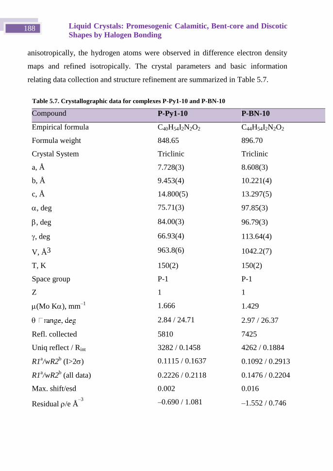
Liquid Crystals: Promesogenic Calamitic, Bent-core and Discotic
Shapes by Halogen Bonding 188
anisotropically, the hydrogen atoms were observed in difference electron density
maps and refined isotropically. The crystal parameters and basic information
relating data collection and structure refinement are summarized in Table 5.7.
Table 5.7. Crystallographic data for complexes P-Py110 and P-BN10
Compound P-Py1-10 P-BN-10
Empirical formula C40H54I2N2O2 C44H54I2N2O2
Formula weight 848.65 896.70
Crystal System Triclinic Triclinic
a, Å 7.728(3) 8.608(3)
b, Å 9.453(4) 10.221(4)
c, Å 14.800(5) 13.297(5)
, deg 75.71(3) 97.85(3)
, deg 84.00(3) 96.79(3)
, deg 66.93(4) 113.64(4)
V, Å3 963.8(6) 1042.2(7)
T, K 150(2) 150(2)
Space group P-1 P-1
Z 1 1
(Mo K), mm–1
1.666 1.429
2.84 / 24.71 2.97 / 26.37
Refl. collected 5810 7425
Uniq reflect / Rint 3282 / 0.1458 4262 / 0.1884
R1a/wR2
b (I>2) 0.1115 / 0.1637 0.1092 / 0.2913
R1a/wR2
b (all data) 0.2226 / 0.2118 0.1476 / 0.2204
Max. shift/esd 0.002 0.016
Residual /e Å–3
–0.690 / 1.081 –1.552 / 0.746
Chapter 5 189
5.10 Bibliography
[1] F. Reinitzer, Monatshefte für Chemie und verwandte Teile anderer Wissenschaften 1888, 9, 421-
441.
[2] a) H. Sackmann, Kristall und Technik 1981, 16, 527-527; b) R. T. a. G. ATTARD in The World
of Liquid Crystals: The fourth state of matter Vol. 1991; c) P. J. Collings., Liquid Crystals, Nature's
Delicate Phase of Matter, IOP Publishing Ltd., England, 1990, p.
[3] a) J. P. F. Lagerwall and G. Scalia, Current Applied Physics 2012, 12, 1387-1412; b) A. M. Lowe
and N. L. Abbott, Chem. Mat. 2012, 24, 746-758; c) J. A. Castellano in The Story of Liquid Crystal
Displays and the Creation of an Industry, Vol. World Scientific Publishing, 2005.
[4] J. W. Steed and J. L. Atwood in The Supramolecular Chemistry of Life, Vol. John Wiley & Sons,
Ltd, 2009, pp. 49-104.
[5] J. W. Goodby, P. J. Collings, T. Kato, C. Tschierske, H. F. Gleeson and P. Raynes in Ionic Self
Assembly and Amphotropic Ionic Liquid Crystals Vol. 6: Nanostructured and Amphiphilic Liquid
Crystals PART II - Amphiphilic Liquid Crystals and Hydrogen-Bonded Systems: Discrete Defined
Aggregates and Intramolecular H-Bonding, Amides, Carboxylic Acids, Heterocycles Vol. 5: Non-
Conventional Liquid Crystals. In Handbook of liquid crystals., Vol. 8 Wiley, 2014.
[6] a) T. Kato and J. M. J. Frechet, Liq. Cryst. 2006, 33, 1429-1433; b) T. Kato, N. Mizoshita and K.
Kishimoto, Angew. Chem. Int. Ed. 2006, 45, 38-68; c) D. Broer, G. P. Crawford and S. Zumer,
Cross-Linked Liquid Crystalline Systems: From Rigid Polymer Networks to Elastomers, Boca
Raton, FL, 2011, p.
[7] a) T. Kato and J. M. J. Frechet, J. Am. Chem. Soc. 1989, 111, 8533-8534; b) T. Kato, P. G.
Wilson, A. Fujishima and J. M. J. Frechet, Chem. Lett. 1990, 2003-2006; c) B. Feringán, P. Romero,
J. L. Serrano, R. Giménez and T. Sierra, Chem. Eur. J. 2015, 21, 8859-8866.
[8] a) N. Gimeno, M. B. Ros, J. L. Serrano and M. R. de la Fuente, Angew. Chem. Int. Ed. 2004, 43,
5235-5238; b) J. Barbera, N. Gimeno, I. Pintre, M. B. Ros and J. L. Serrano, Chem. Commun. 2006,
1212-1214; c) A. Perez, N. Gimeno, F. Vera, M. B. Ros, J. L. Serrano and M. R. De la Fuente, Eur.
J. Org. Chem. 2008, 826-833; d) N. Gimeno, M. B. Ros, J. L. Serrano and M. R. De la Fuente,
Chem. Mat. 2008, 20, 1262-1271; e) L.-Y. Wang, I. H. Chiang, P.-J. Yang, W.-S. Li, I. T. Chao and
H.-C. Lin, J. Phys. Chem. B 2009, 113, 14648-14660; f) L.-Y. Wang, H.-Y. Tsai and H.-C. Lin,
Macromolecules 2010, 43, 1277-1288; g) P.-J. Yang, L.-Y. Wang, C.-Y. Tang and H.-C. Lin, J.
Polymer Science Part a-Polymer Chem. 2010, 48, 764-774; h) W.-H. Chen, W.-T. Chuang, U. S.
Jeng, H.-S. Sheu and H.-C. Lin, J. Am. Chem. Soc. 2011, 133, 15674-15685.
[9] L. C. Gilday, S. W. Robinson, T. A. Barendt, M. J. Langton, B. R. Mullaney and P. D. Beer,
Chem. Rev. 2015, 115, 7118-7195.
[10] a) F. Guthrie, J. Chem. Soc. 1863, 16, 239; b) I. Remses, J. F. Norris and Am. Chem. J. 1896,
18, 90.
[11] a) O. Hassel and J. Hvoslef, Acta Chemica Scandinavica 1954, 8, 873-873; b) O. Hassel and C.
Romming, Quarterly Rev. 1962, 16, 1-18; c) H. A. Bent, Chem. Rev. 1968, 68, 587-&.
[12] a) P. Auffinger, F. A. Hays, E. Westhof and P. S. Ho, Proc. Natl. Acad. Sci. U. S. A. 2004, 101,
16789-16794; b) P. Metrangolo, H. Neukirch, T. Pilati and G. Resnati, Acc. Chem. Res. 2005, 38,
386-395; c) A. R. Voth and P. S. Ho, Curr. Top. Med. Chem. 2007, 7, 1336; d) P. Metrangolo, F.
Meyer, T. Pilati, G. Resnati and G. Terraneo, Angew. Chem. Int. Ed. 2008, 47, 6114-6127; e) M.
Fourmigue, P. Metrangolo and G. Resnati, Halogen Bonding Fundamentals and Applications, 2008,
p; f) L. A. Hardegger, B. Kuhn, B. Spinnler, L. Anselm, R. Ecabert, M. Stihle, B. Gsell, R. Thoma,
J. Diez, J. Benz, J. M. Plancher, G. Hartmann, D. W. Banner, W. Haap and F. Diederich, Angew
Chem Int Ed Engl 2011, 50, 314-318.
[13] H. L. Nguyen, P. N. Horton, M. B. Hursthouse, A. C. Legon and D. W. Bruce, J. Am. Chem.
Soc. 2004, 126, 16-17.
[14] T. Kato, T. Yasuda, Y. Kamikawa and M. Yoshio, Chem. Commun. 2009, 729-739.
Liquid Crystals: Promesogenic Calamitic, Bent-core and Discotic
Shapes by Halogen Bonding 190
[15] a) K. Willis, D. J. Price, H. Adams, G. Ungar and D. W. Bruce, J. Mat. Chem. 1995, 5, 2195-
2199; b) D. J. Price, K. Willis, T. Richardson, G. Ungar and D. W. Bruce, J. Mat. Chem. 1997, 7,
883-891.
[16] a) J. W. Xu, C. L. Toh, X. M. Liu, S. F. Wang, C. B. He and X. H. Lu, Macromolecules 2005,
38, 1684-1690; b) J. W. Xu, X. M. Liu, J. K. P. Ng, T. T. Lin and C. B. He, J. Mat. Chem. 2006, 16,
3540-3545; c) P. Metrangolo, C. Prasang, G. Resnati, R. Liantonio, A. C. Whitwood and D. W.
Bruce, Chem. Commun. 2006, 3290-3292; d) D. W. Bruce, P. Metrangolo, F. Meyer, C. Prasang, G.
Resnati, G. Terraneo and A. C. Whitwood, New J. Chem. 2008, 32, 477-482; e) C. Prasang, A. C.
Whitwood and D. W. Bruce, Chem. Commun. 2008, 2137; f) D. W. Bruce in Halogen-bonded liquid
crystals, Vol. 126 Eds.: P. Metrangolo and G. Resnati), 2008, pp. 161-180; g) D. W. Bruce, P.
Metrangolo, F. Meyer, T. Pilati, C. Prasang, G. Resnati, G. Terraneo, S. G. Wainwright and A. C.
Whitwood, Chem. Eur. J. 2010, 16, 9511-9524.
[17] L. J. McAllister, C. Prasang, J. P. W. Wong, R. J. Thatcher, A. C. Whitwood, B. Donnio, P.
O'Brien, P. B. Karadakov and D. W. Bruce, Chem. Commun. 2013, 49, 3946.
[18] L. Gonzalez, N. Gimeno, R. Maria Tejedor, V. Polo, M. Blanca Ros, S. Uriel and J. Luis
Serrano, Chem. Mat. 2013, 25, 4503-4510.
[19] Y. Chen, H. Yu, L. Zhang, H. Yang and Y. Lu, Chem. Commun. 2014, 50, 9647-9649.
[20] a) C. Laurence, M. Queigneccabanetos, T. Dziembowska, R. Queignec and B. Wojtkowiak, J.
Am. Chem. Soc. 1981, 103, 2567-2573; b) C. Laurence, M. Queigneccabanetos and B. Wojtkowiak,
J. Chem. Soc. Perkin Trans. 2 1982, 1605-1610; c) C. Laurence, M. Queigneccabanetos and B.
Wojtkowiak, Can. J. Chem. 1983, 61, 135-138.
[21] a) H. M. Yamamoto, Y. Kosaka, R. Maeda, J. Yamaura, A. Nakao, T. Nakamura and R. Kato,
ACS Nano 2008, 2, 143-155; b) J. Lieffrig, H. M. Yamamoto, T. Kusamoto, H. Cui, O. Jeannin, M.
Fourmigue and R. Kato, Cryst. Growth Des. 2011, 11, 4267-4271.
[22] A. W. Sun, J. W. Lauher and N. S. Goroff, Science 2006, 312, 1030-1034.
[23] L. Luo, C. Wilhelm, A. Sun, C. P. Grey, J. W. Lauher and N. S. Goroff, J. Am. Chem. Soc.
2008, 130, 7702-7709.
[24] A. Brun and G. Etemad-Moghadam, Synthesis 2002, 1385-1390.
[25] a) J. Ruokolainen, J. Tanner, G. Tenbrinke, O. Ikkala, M. Torkkeli and R. Serimaa,
Macromolecules 1995, 28, 7779-7784; b) J. Ruokolainen, G. tenBrinke, O. Ikkala, M. Torkkeli and
R. Serimaa, Macromolecules 1996, 29, 3409-3415.
[26] a) X. Zhou, S. H. Goh, S. Y. Lee and K. L. Tan, Appl. Surf. Sci. 1997, 119, 60-66; b) F. Wang,
N. Ma, Q. Chen, W. Wang and L. Wang, Langmuir 2007, 23, 9540-9542.
[27] A. Priimagi, G. Cavallo, A. Forni, M. Gorynsztejn-Leben, M. Kaivola, P. Metrangolo, R.
Milani, A. Shishido, T. Pilati, G. Resnati and G. Terraneo, Adv. Funct. Mater. 2012, 22, 2572-2579.
[28] A. L. Barres, A. El-Ghayoury, L. V. Zorina, E. Canadell, P. Auban-Senzier and P. Batail, Chem.
Commun. 2008, 2194-2196.
[29] a) S. K. Maity, S. Bera, A. Paikar, A. Pramanik and D. Haldar, Chem Commun (Camb) 2013,
49, 9051-9053; b) N. Nagels, D. Hauchecorne and W. A. Herrebout, Molecules 2013, 18, 6829-
6851.
[30] a) A. Velazquez-Campoy and E. Freire, Nat. Protocols 2006, 1, 186-191; b) A. Velazquez-
Campoy, S. Leavitt and E. Freire in Characterization of Protein-Protein Interactions by Isothermal
Titration Calorimetry, Vol. 1278 Eds.: C. L. Meyerkord and H. Fu), Springer New York, 2015, pp.
183-204.
[31] S. M. Walter, F. Kniep, L. Rout, F. P. Schmidtchen, E. Herdtweck and S. M. Huber, J. Am.
Chem. Soc. 2012, 134, 8507-8512.
[32] A. Eremin, S. Diele, G. Pelzl, H. Nadasi, W. Weissflog, J. Salfetnikova and H. Kresse, Phys.
Rev. E 2001, 64.
[33] B. K. Sadashiva, R. A. Reddy, R. Pratibha and N. V. Madhusudana, J. Mat. Chem. 2002, 12,
943-950.
Chapter 5 191
[34] a) R. A. Reddy and B. K. Sadashiva, J. Mat. Chem. 2004, 14, 310-319; b) D. Pociecha, M.
Cepic, E. Gorecka and J. Mieczkowski, Phys. Rev. Lett. 2003, 91.
[35] Y. Shimbo, E. Gorecka, D. Pociecha, F. Araoka, M. Goto, Y. Takanishi, K. Ishikawa, J.
Mieczkowski, K. Gomola and H. Takezoe, Phys. Rev. Lett. 2006, 97.
[36] a) K. Gomola, L. Guo, D. Pociecha, F. Araoka, K. Ishikawa and H. Takezoe, J. Mat. Chem.
2010, 20, 7944-7952; b) L. Guo, S. Dhara, B. K. Sadashiva, S. Radhika, R. Pratibha, Y. Shimbo, F.
Araoka, K. Ishikawa and H. Takezoe, Phys. Rev. E 2010, 81.
[37] S. Tsuzuki, A. Wakisaka, T. Ono and T. Sonoda, Chem. Eur. J. 2012, 18, 951-960.
[38] K. Wendler, J. Thar, S. Zahn and B. Kirchner, J. Phys. Chem. A 2010, 114, 9529-9536.
[39] a) P. Politzer, J. S. Murray and P. Lane, Int. J. Quantum Chem. 2007, 107, 3046-3052; b) P.
Politzer, J. S. Murray and T. Clark, Phys. Chem. Chem. Phys. 2010, 12, 7748-7757.
[40] G. W. T. J. Frisch, H. B. Schlegel, G. E. Scuseria, M. A. Robb, J. R. Cheeseman, G. Scalmani,
V. Barone, G. A. Petersson, H. Nakatsuji, X. Li, M. Caricato, A. Marenich, J. Bloino, B. G. Janesko,
R. Gomperts, B. Mennucci, H. P. Hratchian, J. V. Ortiz, A. F. Izmaylov, J. L. Sonnenberg, D.
Williams-Young, F. Ding, F. Lipparini, F. Egidi, J. Goings, B. Peng, A. Petrone, T. Henderson, D.
Ranasinghe, V. G. Zakrzewski, J. Gao, N. Rega, G. Zheng, W. Liang, M. Hada, M. Ehara, K.
Toyota, R. Fukuda, J. Hasegawa, M. Ishida, T. Nakajima, Y. Honda, O. Kitao, H. Nakai, T. Vreven,
K. Throssell, J. A. Montgomery, Jr., J. E. Peralta, F. Ogliaro, M. Bearpark, J. J. Heyd, E. Brothers,
K. N. Kudin, V. N. Staroverov, T. Keith, R. Kobayashi, J. Normand, K. Raghavachari, A. Rendell, J.
C. Burant, S. S. Iyengar, J. Tomasi, M. Cossi, J. M. Millam, M. Klene, C. Adamo, R. Cammi, J. W.
Ochterski, R. L. Martin, K. Morokuma, O. Farkas, J. B. Foresman, and D. J. Fox, in Gaussian 09,
Vol. Gaussian Inc., Wallingford CT, 2009.
[41] a) P. M. W. Gill, Mol. Phys. 1996, 89, 433-445; b) J. P. Perdew, K. Burke and M. Ernzerhof,
Phys. Rev. Lett. 1996, 77, 3865-3868.
[42] W. J. Hehre, L. Radom, S. P. V. R. and J. A. Pople in Ab initio Molecular Orbital Theory, Vol.
Wiley, New York, 1986.
[43] N. Godbout, D. R. Salahub, J. Andzelm and E. Wimmer, Can. J. Chem. 1992, 70, 560-571.
[44] J. P. Merrick, D. Moran and L. Radom, J. Phys. Chem. A 2007, 111, 11683-11700.
[45] S. F. Boys and F. Bernardi, Mol. Phys. 1970, 19, 553-566.
[46] A. E. Reed, L. A. Curtiss and F. Weinhold, Chem. Rev. 1988, 88, 899-926.
[47] Siemens, XSCANS 1994, Siemens Analytical X-ray Instruments Inc., Madison, Wisconsin,
USA.
[48] in CrysAlis Vol. 2006.
[49] G. Sheldrick, Acta Cryst A 2008, 64, 112-122.

Chapter 6 Coordination Metal Complexes
Based on 4-Iodo-N-(4-pyridyl)benzamide,
a Polyfunctional Ligand

Chapter 6 195
6.1 Introduction.
The construction of metal-organic coordination polymers with a variety of
topologies and structural diversity, which affect and control the macroscopic
properties,[1]
has given rise to electrical,[2]
optical,[3]
photoluminescence, gas
storage,[4]
and ion exchange materials. One of the most powerful strategies
employed to regulate the solid-state structure is the arrangement of metallotectons
by non-covalent interactions. The coexistence of metal coordination bonds and
hydrogen bonds has resulted in a wide variety of one-dimensional to three-
dimensional[5]
structures. Recently, halogen-related interactions, including halogen
bonding and related halogen···halogen and halogen···π intermolecular interactions,
have become attractive tools in crystal engineering. However, the presence of
halogen bonding in metal coordination polymers has not received a great deal of
attention.[6]
This chapter is a continuation of the work begun by Sara Graus,[7]
who explored the
design of solid state structures based on molecules that use metal-ligand
coordination, hydrogen and halogen bonding, and -stacking interactions as
directional motifs to guide the self-assembly of network structures. To this end, we
considered it of value to employ the ligand 4-iodo-N-(4-pyridyl)benzamide
(INPBA) (Scheme 6.1), which possesses one pyridine ring for coordination to
metal centers, a carboxamide group that can act as a hydrogen bond donor and
acceptor and one iodine atom that is potentially capable of partaking in oxygen (or
nitrogen), C−I···π and C−I···X−M halogen bonding. Metal-bound halides and
pseudohalides are strongly nucleophilic and serve as halogen bonding acceptors –
as reported by the Brammer and Ward groups, who employed halometallates and
cyanometallates as halogen bond acceptors.[8]
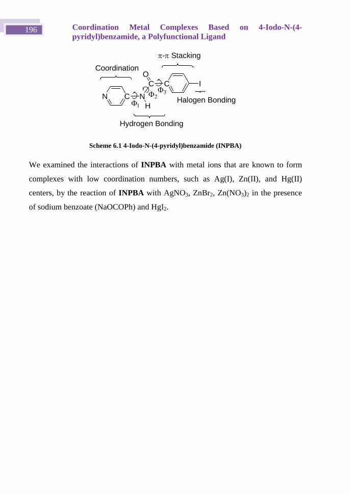
Coordination Metal Complexes Based on 4-Iodo-N-(4-
pyridyl)benzamide, a Polyfunctional Ligand 196
Scheme 6.1 4-Iodo-N-(4-pyridyl)benzamide (INPBA)
We examined the interactions of INPBA with metal ions that are known to form
complexes with low coordination numbers, such as Ag(I), Zn(II), and Hg(II)
centers, by the reaction of INPBA with AgNO3, ZnBr2, Zn(NO3)2 in the presence
of sodium benzoate (NaOCOPh) and HgI2.
N C N
C
H
O
C I
Coordination
Hydrogen Bonding
Halogen Bonding
- Stacking
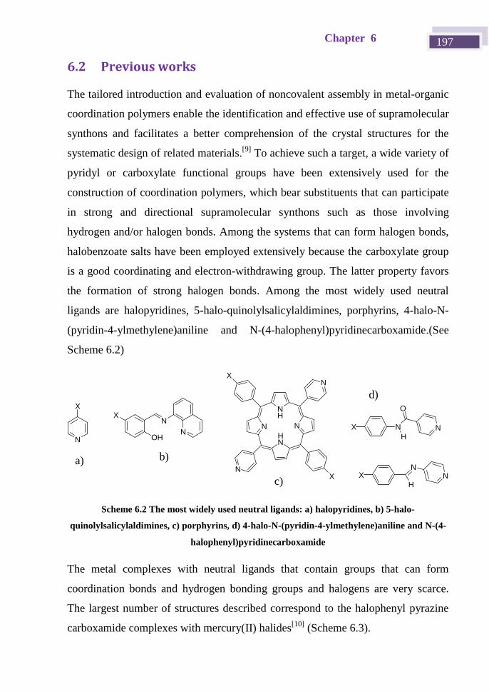
Chapter 6 197
6.2 Previous works
The tailored introduction and evaluation of noncovalent assembly in metal-organic
coordination polymers enable the identification and effective use of supramolecular
synthons and facilitates a better comprehension of the crystal structures for the
systematic design of related materials.[9]
To achieve such a target, a wide variety of
pyridyl or carboxylate functional groups have been extensively used for the
construction of coordination polymers, which bear substituents that can participate
in strong and directional supramolecular synthons such as those involving
hydrogen and/or halogen bonds. Among the systems that can form halogen bonds,
halobenzoate salts have been employed extensively because the carboxylate group
is a good coordinating and electron-withdrawing group. The latter property favors
the formation of strong halogen bonds. Among the most widely used neutral
ligands are halopyridines, 5-halo-quinolylsalicylaldimines, porphyrins, 4-halo-N-
(pyridin-4-ylmethylene)aniline and N-(4-halophenyl)pyridinecarboxamide.(See
Scheme 6.2)
N
NOH
X
N
X
NX
H
O
NN
NH
N
HN
N
N
X
X X
H
NN
Scheme 6.2 The most widely used neutral ligands: a) halopyridines, b) 5-halo-
quinolylsalicylaldimines, c) porphyrins, d) 4-halo-N-(pyridin-4-ylmethylene)aniline and N-(4-
halophenyl)pyridinecarboxamide
The metal complexes with neutral ligands that contain groups that can form
coordination bonds and hydrogen bonding groups and halogens are very scarce.
The largest number of structures described correspond to the halophenyl pyrazine
carboxamide complexes with mercury(II) halides[10]
(Scheme 6.3).
a) b)
c)
d)
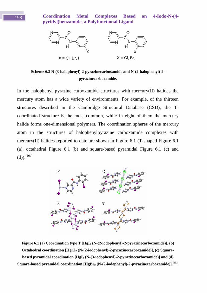
Coordination Metal Complexes Based on 4-Iodo-N-(4-
pyridyl)benzamide, a Polyfunctional Ligand 198
Scheme 6.3 N-(3-halophenyl)-2-pyrazinecarboxamide and N-(2-halophenyl)-2-
pyrazinecarboxamide.
In the halophenyl pyrazine carboxamide structures with mercury(II) halides the
mercury atom has a wide variety of environments. For example, of the thirteen
structures described in the Cambridge Structural Database (CSD), the T-
coordinated structure is the most common, while in eight of them the mercury
halide forms one-dimensional polymers. The coordination spheres of the mercury
atom in the structures of halophenylpyrazine carboxamide complexes with
mercury(II) halides reported to date are shown in Figure 6.1 (T-shaped Figure 6.1
(a), octahedral Figure 6.1 (b) and square-based pyramidal Figure 6.1 (c) and
(d)).[10a]
Figure 6.1 (a) Coordination type T [HgI2 (N-(2-iodophenyl)-2-pyrazinecarboxamide)], (b)
Octahedral coordination [HgCl2 (N-(2-iodophenyl)-2-pyrazinecarboxamide)], (c) Square-
based pyramidal coordination [HgI2 (N-(3-iodophenyl)-2-pyrazinecarboxamide)] and (d)
Square-based pyramidal coordination [HgBr2 (N-(2-iodophenyl)-2-pyrazinecarboxamide)].[10a]
C N
O N
N
X H
X = C l , B r , I
C N
O N
N H
X = C l , B r , I
X
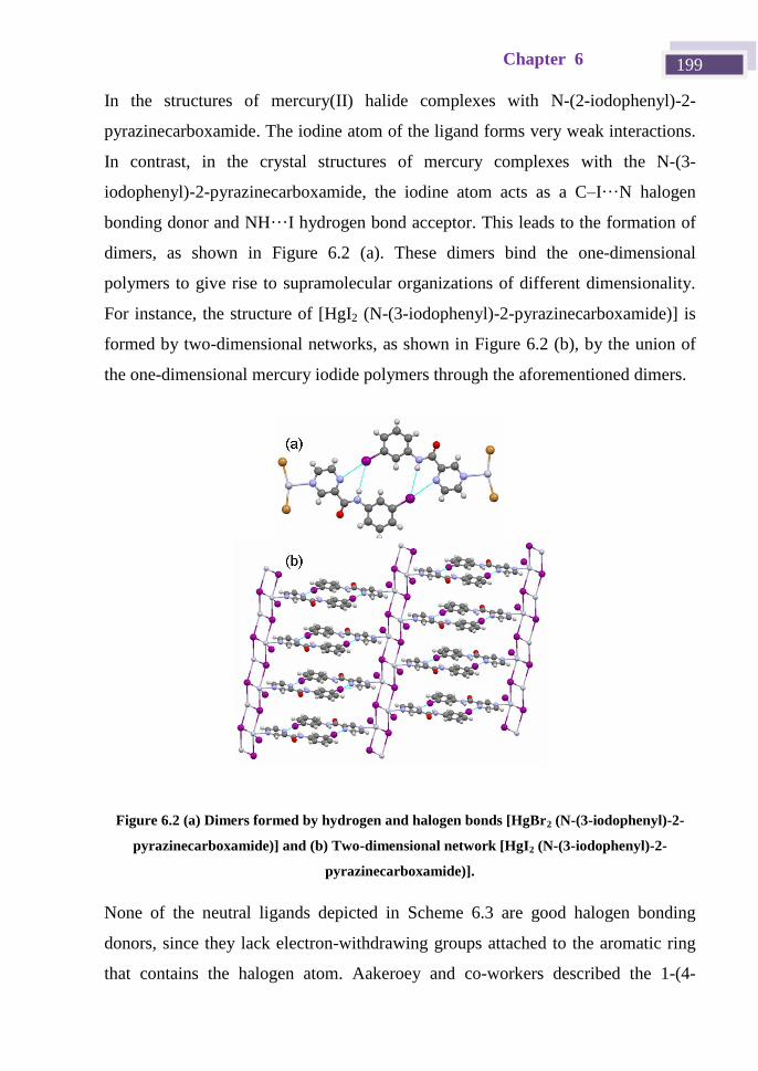
Chapter 6 199
In the structures of mercury(II) halide complexes with N-(2-iodophenyl)-2-
pyrazinecarboxamide. The iodine atom of the ligand forms very weak interactions.
In contrast, in the crystal structures of mercury complexes with the N-(3-
iodophenyl)-2-pyrazinecarboxamide, the iodine atom acts as a C–I···N halogen
bonding donor and NH···I hydrogen bond acceptor. This leads to the formation of
dimers, as shown in Figure 6.2 (a). These dimers bind the one-dimensional
polymers to give rise to supramolecular organizations of different dimensionality.
For instance, the structure of [HgI2 (N-(3-iodophenyl)-2-pyrazinecarboxamide)] is
formed by two-dimensional networks, as shown in Figure 6.2 (b), by the union of
the one-dimensional mercury iodide polymers through the aforementioned dimers.
Figure 6.2 (a) Dimers formed by hydrogen and halogen bonds [HgBr2 (N-(3-iodophenyl)-2-
pyrazinecarboxamide)] and (b) Two-dimensional network [HgI2 (N-(3-iodophenyl)-2-
pyrazinecarboxamide)].
None of the neutral ligands depicted in Scheme 6.3 are good halogen bonding
donors, since they lack electron-withdrawing groups attached to the aromatic ring
that contains the halogen atom. Aakeroey and co-workers described the 1-(4-
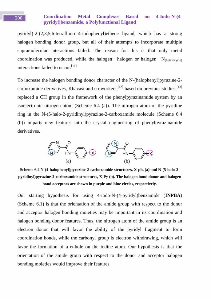
Coordination Metal Complexes Based on 4-Iodo-N-(4-
pyridyl)benzamide, a Polyfunctional Ligand 200
pyridyl)-2-(2,3,5,6-tetrafluoro-4-iodophenyl)ethene ligand, which has a strong
halogen bonding donor group, but all of their attempts to incorporate multiple
supramolecular interactions failed. The reason for this is that only metal
coordination was produced, while the halogen···halogen or halogen···N(heterocycle)
interactions failed to occur.[11]
To increase the halogen bonding donor character of the N-(halophenyl)pyrazine-2-
carboxamide derivatives, Khavasi and co-workers,[12]
based on previous studies,[13]
replaced a CH group in the framework of the phenylpyrazinamide system by an
isoelectronic nitrogen atom (Scheme 6.4 (a)). The nitrogen atom of the pyridine
ring in the N-(5-halo-2-pyridinyl)pyrazine-2-carboxamide molecule (Scheme 6.4
(b)) imparts new features into the crystal engineering of phenylpyrazinamide
derivatives.
N
N
HN X
O
N
N
HN
N
X
O
Scheme 6.4 N-(4-halophenyl)pyrazine-2-carboxamide structures, X-ph, (a) and N-(5-halo-2-
pyridinyl)pyrazine-2-carboxamide structures, X-Py (b). The halogen bond donor and halogen
bond acceptors are shown in purple and blue circles, respectively.
Our starting hypothesis for using 4-iodo-N-(4-pyridyl)benzamide (INPBA)
(Scheme 6.1) is that the orientation of the amide group with respect to the donor
and acceptor halogen bonding moieties may be important in its coordination and
halogen bonding donor features. Thus, the nitrogen atom of the amide group is an
electron donor that will favor the ability of the pyridyl fragment to form
coordination bonds, while the carbonyl group is electron withdrawing, which will
favor the formation of a -hole on the iodine atom. Our hypothesis is that the
orientation of the amide group with respect to the donor and acceptor halogen
bonding moieties would improve their features.
(a) (b)
Chapter 6 201
We report the synthesis and crystal structure of INPBA (1) and four metal INPBA
coordination supramolecular and polymeric structures [Ag(INPBA)2]NO3 (2),
[ZnBr2(INPBA)2] (3), [Zn(OCOPh)2(INPBA)2] (4), and [HgI2(INPBA)]n (5). In
4, benzoic acid was used as an ancillary ligand. The interactions and contacts in
structures were analyzed by Hirshfeld surface calculations. The capacity of INPBA
as a halogen bonding donor was evaluated by DFT calculations and comparison
with crystal structures of other halogen bonding donors.
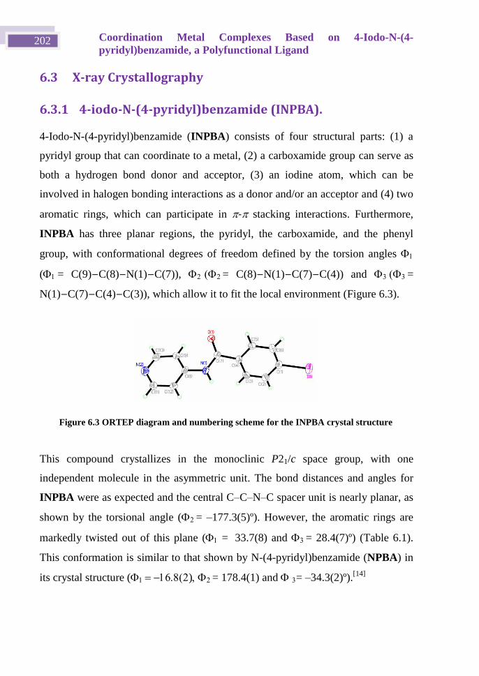
Coordination Metal Complexes Based on 4-Iodo-N-(4-
pyridyl)benzamide, a Polyfunctional Ligand 202
6.3 X-ray Crystallography
6.3.1 4-iodo-N-(4-pyridyl)benzamide (INPBA).
4-Iodo-N-(4-pyridyl)benzamide (INPBA) consists of four structural parts: (1) a
pyridyl group that can coordinate to a metal, (2) a carboxamide group can serve as
both a hydrogen bond donor and acceptor, (3) an iodine atom, which can be
involved in halogen bonding interactions as a donor and/or an acceptor and (4) two
aromatic rings, which can participate in - stacking interactions. Furthermore,
INPBA has three planar regions, the pyridyl, the carboxamide, and the phenyl
group, with conformational degrees of freedom defined by the torsion angles
(= C(9)−C(8)−N(1)−C(7)), = C(8)−N(1)−C(7)−C(4)) and =
N(1)−C(7)−C(4)−C(3)), which allow it to fit the local environment (Figure 6.3).
This compound crystallizes in the monoclinic P21/c space group, with one
independent molecule in the asymmetric unit. The bond distances and angles for
INPBA were as expected and the central C–C–N–C spacer unit is nearly planar, as
shown by the torsional angle (= –177.3(5)º). However, the aromatic rings are
markedly twisted out of this plane (= 33.7(8) and = 28.4(7)º) (Table 6.1).
This conformation is similar to that shown by N-(4-pyridyl)benzamide (NPBA) in
its crystal structure ()= 178.4(1) and = –34.3(2)º).[14]
Figure 6.3 ORTEP diagram and numbering scheme for the INPBA crystal structure
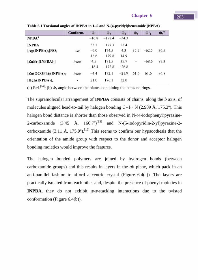
Chapter 6 203
Table 6.1 Torsional angles of INPBA in 1–5 and N-(4-pyridyl)benzamide (NPBA)
Conform. '4 b
NPBAa –16.8 –178.4 –34.3
INPBA 33.7 –177.3 28.4
[Ag(INPBA)2]NO3 cis –6.0 174.5 4.3 35.7 –62.5 36.5
16.6 –179.8 14.9
[ZnBr2(INPBA)2] trans 4.5 171.5 35.7 –
56.7
–68.6 87.3
–18.4 –172.8 –26.8
[Zn(OCOPh)2(INPBA)2
]
trans –4.4 172.1 –21.9 61.6 61.6 86.8
[HgI2(INPBA)]n - 21.0 176.1 32.0
(a) Ref.[14]
; (b) angle between the planes containing the benzene rings.
The supramolecular arrangement of INPBA consists of chains, along the b axis, of
molecules aligned head-to-tail by halogen bonding C−I···N (2.989 Å, 175.3º). This
halogen bond distance is shorter than those observed in N-(4-iodophenyl)pyrazine-
2-carboxamide (3.45 Å, 166.7º)[15]
and N-(5-iodopyridin-2-yl)pyrazine-2-
carboxamide (3.11 Å, 175.9º).[15]
This seems to confirm our hypsoothesis that the
orientation of the amide group with respect to the donor and acceptor halogen
bonding moieties would improve the features.
The halogen bonded polymers are joined by hydrogen bonds (between
carboxamide groups) and this results in layers in the ab plane, which pack in an
anti-parallel fashion to afford a centric crystal (Figure 6.4(a)). The layers are
practically isolated from each other and, despite the presence of phenyl moieties in
INPBA, they do not exhibit --stacking interactions due to the twisted
conformation (Figure 6.4(b)).
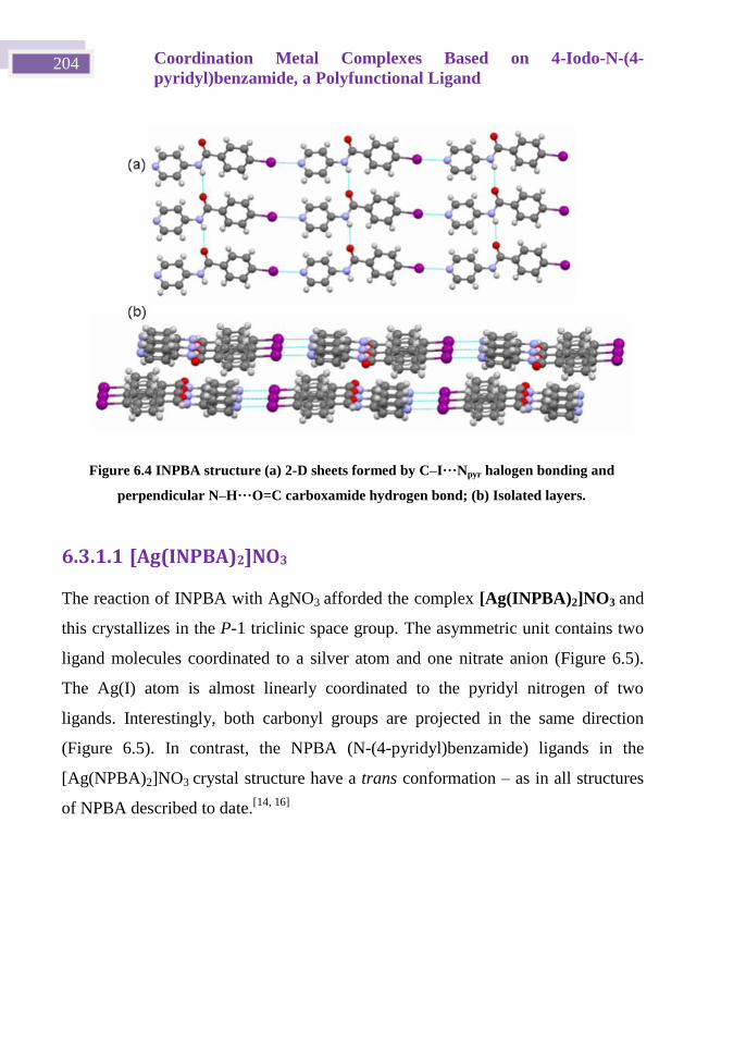
Coordination Metal Complexes Based on 4-Iodo-N-(4-
pyridyl)benzamide, a Polyfunctional Ligand 204
6.3.1.1 [Ag(INPBA)2]NO3
The reaction of INPBA with AgNO3 afforded the complex [Ag(INPBA)2]NO3 and
this crystallizes in the P-1 triclinic space group. The asymmetric unit contains two
ligand molecules coordinated to a silver atom and one nitrate anion (Figure 6.5).
The Ag(I) atom is almost linearly coordinated to the pyridyl nitrogen of two
ligands. Interestingly, both carbonyl groups are projected in the same direction
(Figure 6.5). In contrast, the NPBA (N-(4-pyridyl)benzamide) ligands in the
[Ag(NPBA)2]NO3 crystal structure have a trans conformation – as in all structures
of NPBA described to date.[14, 16]
Figure 6.4 INPBA structure (a) 2-D sheets formed by C–I···Npyr halogen bonding and
perpendicular N–H···O=C carboxamide hydrogen bond; (b) Isolated layers.
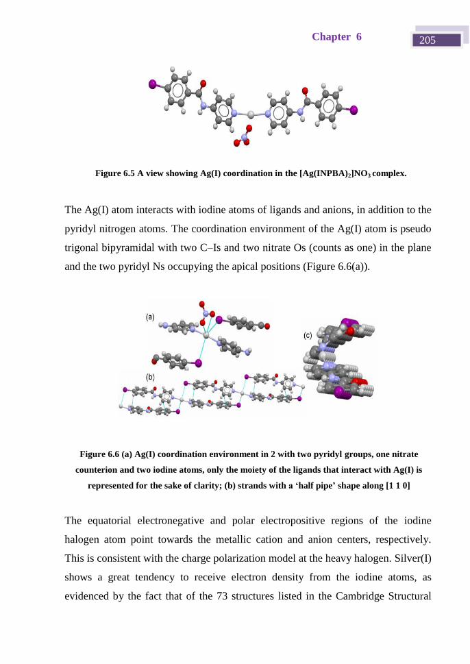
Chapter 6 205
The Ag(I) atom interacts with iodine atoms of ligands and anions, in addition to the
pyridyl nitrogen atoms. The coordination environment of the Ag(I) atom is pseudo
trigonal bipyramidal with two C–Is and two nitrate Os (counts as one) in the plane
and the two pyridyl Ns occupying the apical positions (Figure 6.6(a)).
The equatorial electronegative and polar electropositive regions of the iodine
halogen atom point towards the metallic cation and anion centers, respectively.
This is consistent with the charge polarization model at the heavy halogen. Silver(I)
shows a great tendency to receive electron density from the iodine atoms, as
evidenced by the fact that of the 73 structures listed in the Cambridge Structural
Figure 6.6 (a) Ag(I) coordination environment in 2 with two pyridyl groups, one nitrate
counterion and two iodine atoms, only the moiety of the ligands that interact with Ag(I) is
represented for the sake of clarity; (b) strands with a ‘half pipe’ shape along [1 1 0]
direction.
Figure 6.5 A view showing Ag(I) coordination in the [Ag(INPBA)2]NO3 complex.
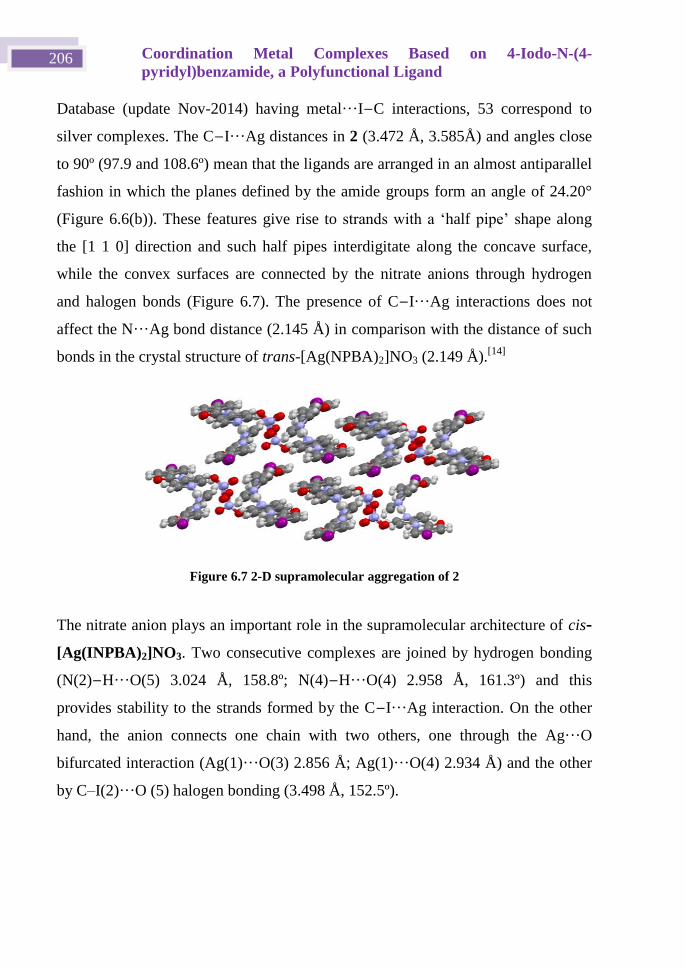
Coordination Metal Complexes Based on 4-Iodo-N-(4-
pyridyl)benzamide, a Polyfunctional Ligand 206
Database (update Nov-2014) having metal···I−C interactions, 53 correspond to
silver complexes. The C−I···Ag distances in 2 (3.472 Å, 3.585Å) and angles close
to 90º (97.9 and 108.6º) mean that the ligands are arranged in an almost antiparallel
fashion in which the planes defined by the amide groups form an angle of 24.20°
(Figure 6.6(b)). These features give rise to strands with a ‘half pipe’ shape along
the [1 1 0] direction and such half pipes interdigitate along the concave surface,
while the convex surfaces are connected by the nitrate anions through hydrogen
and halogen bonds (Figure 6.7). The presence of C−I···Ag interactions does not
affect the N···Ag bond distance (2.145 Å) in comparison with the distance of such
bonds in the crystal structure of trans-[Ag(NPBA)2]NO3 (2.149 Å).[14]
The nitrate anion plays an important role in the supramolecular architecture of cis-
[Ag(INPBA)2]NO3. Two consecutive complexes are joined by hydrogen bonding
(N(2)−H···O(5) 3.024 Å, 158.8º; N(4)−H···O(4) 2.958 Å, 161.3º) and this
provides stability to the strands formed by the C−I···Ag interaction. On the other
hand, the anion connects one chain with two others, one through the Ag···O
bifurcated interaction (Ag(1)···O(3) 2.856 Å; Ag(1)···O(4) 2.934 Å) and the other
by C–I(2)···O (5) halogen bonding (3.498 Å, 152.5º).
Figure 6.7 2-D supramolecular aggregation of 2
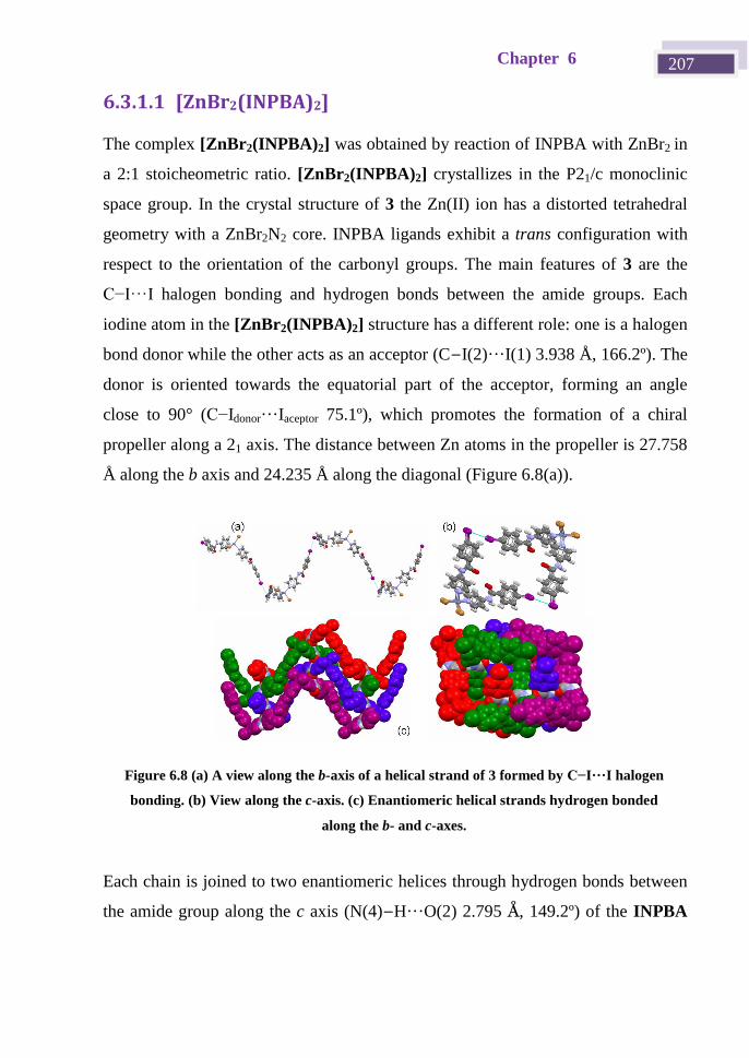
Chapter 6 207
6.3.1.1 [ZnBr2(INPBA)2]
The complex [ZnBr2(INPBA)2] was obtained by reaction of INPBA with ZnBr2 in
a 2:1 stoicheometric ratio. [ZnBr2(INPBA)2] crystallizes in the P21/c monoclinic
space group. In the crystal structure of 3 the Zn(II) ion has a distorted tetrahedral
geometry with a ZnBr2N2 core. INPBA ligands exhibit a trans configuration with
respect to the orientation of the carbonyl groups. The main features of 3 are the
C−I···I halogen bonding and hydrogen bonds between the amide groups. Each
iodine atom in the [ZnBr2(INPBA)2] structure has a different role: one is a halogen
bond donor while the other acts as an acceptor (C−I(2)···I(1) 3.938 Å, 166.2º). The
donor is oriented towards the equatorial part of the acceptor, forming an angle
close to 90° (C−Idonor···Iaceptor 75.1º), which promotes the formation of a chiral
propeller along a 21 axis. The distance between Zn atoms in the propeller is 27.758
Å along the b axis and 24.235 Å along the diagonal (Figure 6.8(a)).
Each chain is joined to two enantiomeric helices through hydrogen bonds between
the amide group along the c axis (N(4)−H···O(2) 2.795 Å, 149.2º) of the INPBA
Figure 6.8 (a) A view along the b-axis of a helical strand of 3 formed by C−I···I halogen
bonding. (b) View along the c-axis. (c) Enantiomeric helical strands hydrogen bonded
along the b- and c-axes.
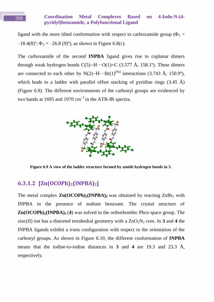
Coordination Metal Complexes Based on 4-Iodo-N-(4-
pyridyl)benzamide, a Polyfunctional Ligand 208
ligand with the more tilted conformation with respect to carboxamide group (1 =
–18.4(8)º; 3 = –26.8 (9)º), as shown in Figure 6.8(c).
The carboxamide of the second INPBA ligand gives rise to coplanar dimers
through weak hydrogen bonds C(5)−H···O(1)=C (3.577 Å, 158.1º). These dimers
are connected to each other by N(2)−H···Br(1)[9a]
interactions (3.743 Å, 150.9º),
which leads to a ladder with parallel offset stacking of pyridine rings (3.45 Å)
(Figure 6.9). The different environments of the carbonyl groups are evidenced by
two bands at 1695 and 1970 cm–1
in the ATR-IR spectra.
6.3.1.2 [Zn(OCOPh)2(INPBA)2]
The metal complex Zn(OCOPh)2(INPBA)2 was obtained by reacting ZnBr2 with
INPBA in the presence of sodium benzoate. The crystal structure of
Zn(OCOPh)2(INPBA)2 (4) was solved in the orthorhombic Pbcn space group. The
zinc(II) ion has a distorted tetrahedral geometry with a ZnO2N2 core. In 3 and 4 the
INPBA ligands exhibit a trans configuration with respect to the orientation of the
carbonyl groups. As shown in Figure 6.10, the different conformation of INPBA
means that the iodine-to-iodine distances in 3 and 4 are 19.3 and 23.3 Å,
respectively.
Figure 6.9 A view of the ladder structure formed by amide hydrogen bonds in 3.
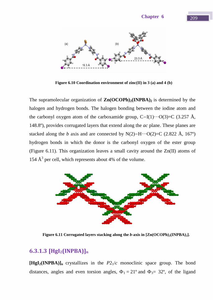
Chapter 6 209
The supramolecular organization of Zn(OCOPh)2(INPBA)2 is determined by the
halogen and hydrogen bonds. The halogen bonding between the iodine atom and
the carbonyl oxygen atom of the carboxamide group, C−I(1)···O(3)=C (3.257 Å,
148.8º), provides corrugated layers that extend along the ac plane. These planes are
stacked along the b axis and are connected by N(2)−H···O(2)=C (2.822 Å, 167º)
hydrogen bonds in which the donor is the carbonyl oxygen of the ester group
(Figure 6.11). This organization leaves a small cavity around the Zn(II) atoms of
154 Å3 per cell, which represents about 4% of the volume.
6.3.1.3 [HgI2(INPBA)]n
[HgI2(INPBA)]n crystallizes in the P21/c monoclinic space group. The bond
distances, angles and even torsion angles, 1=21ºand 3= 32º, of the ligand
Figure 6.11 Corrugated layers stacking along the b-axis in [Zn(OCOPh)2(INPBA)2].
Figure 6.10 Coordination environment of zinc(II) in 3 (a) and 4 (b)
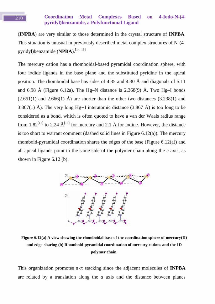
Coordination Metal Complexes Based on 4-Iodo-N-(4-
pyridyl)benzamide, a Polyfunctional Ligand 210
(INPBA) are very similar to those determined in the crystal structure of INPBA.
This situation is unusual in previously described metal complex structures of N-(4-
pyridyl)benzamide (NPBA).[14, 16]
The mercury cation has a rhomboidal-based pyramidal coordination sphere, with
four iodide ligands in the base plane and the substituted pyridine in the apical
position. The rhomboidal base has sides of 4.35 and 4.30 Å and diagonals of 5.11
and 6.98 Å (Figure 6.12a). The Hg–N distance is 2.368(9) Å. Two Hg–I bonds
(2.651(1) and 2.666(1) Å) are shorter than the other two distances (3.238(1) and
3.867(1) Å). The very long Hg−I interatomic distance (3.867 Å) is too long to be
considered as a bond, which is often quoted to have a van der Waals radius range
from 1.82[17]
to 2.24 Å[18]
for mercury and 2.1 Å for iodine. However, the distance
is too short to warrant comment (dashed solid lines in Figure 6.12(a)). The mercury
rhomboid-pyramidal coordination shares the edges of the base (Figure 6.12(a)) and
all apical ligands point to the same side of the polymer chain along the c axis, as
shown in Figure 6.12 (b).
This organization promotes - stacking since the adjacent molecules of INPBA
are related by a translation along the a axis and the distance between planes
Figure 6.12(a) A view showing the rhomboidal base of the coordination sphere of mercury(II)
and edge-sharing (b) Rhomboid-pyramidal coordination of mercury cations and the 1D
polymer chain.
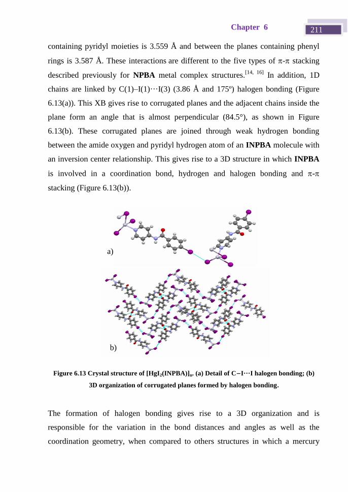
Chapter 6 211
containing pyridyl moieties is 3.559 Å and between the planes containing phenyl
rings is 3.587 Å. These interactionsare different to the five types of - stacking
described previously for NPBA metal complex structures.[14, 16]
In addition, 1D
chains are linked by C(1)–I(1)···I(3) (3.86 Å and 175º) halogen bonding (Figure
6.13(a)). This XB gives rise to corrugated planes and the adjacent chains inside the
plane form an angle that is almost perpendicular (84.5°), as shown in Figure
6.13(b). These corrugated planes are joined through weak hydrogen bonding
between the amide oxygen and pyridyl hydrogen atom of an INPBA molecule with
an inversion center relationship. This gives rise to a 3D structure in which INPBA
is involved in a coordination bond, hydrogen and halogen bonding and -
stacking (Figure 6.13(b)).
The formation of halogen bonding gives rise to a 3D organization and is
responsible for the variation in the bond distances and angles as well as the
coordination geometry, when compared to others structures in which a mercury
Figure 6.13 Crystal structure of [HgI2(INPBA)]n. (a) Detail of C−I···I halogen bonding; (b)
3D organization of corrugated planes formed by halogen bonding.
a)
b)
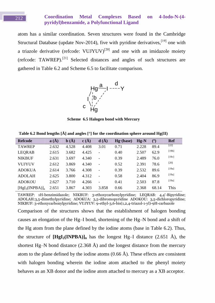
Coordination Metal Complexes Based on 4-Iodo-N-(4-
pyridyl)benzamide, a Polyfunctional Ligand 212
atom has a similar coordination. Seven structures were found in the Cambridge
Structural Database (update Nov-2014), five with pyridine derivatives,[19]
one with
a triazole derivative (refcode: VUJYUV)[20]
and one with an imidazole moiety
(refcode: TAWREP).[21]
Selected distances and angles of such structures are
gathered in Table 6.2 and Scheme 6.5 to facilitate comparison.
Table 6.2 Bond lengths [Å] and angles [°] for the coordination sphere around Hg(II)
Refcode a (Å) b (Å) c (Å) d (Å) Hg_(base) Hg-N (º) Ref
TAWREP 2.632 4.528 4.408 3.01 0.71 2.228 89.4 [22]
LEQRAB 2.615 3.682 4.425 - 0.40 2.507 62.9 [19b]
NIKBUF 2.631 3.697 4.340 - 0.39 2.489 76.0 [19c]
VUJYUV 2.612 3.869 4.340 - 0.52 2.391 78.6 [20]
ADOKUA 2.614 3.766 4.308 - 0.39 2.532 89.6 [19a]
ADOLAH 2.625 3.800 4.312 - 0.58 2.404 86.9 [19a]
ADOKOU 2.627 3.710 4.266 - 0.41 2.503 87.8 [19a]
[HgI2(INPBA)]n 2.651 3.867 4.303 3.858 0.66 2.368 68.14 This
work TAWREP: 1H-benzimidazole; NIKBUF: 3-ethoxycarbonylpyridine; LEQRAB: 4,4'-Bipyridine; ADOLAH:3,5-dimethylpyridine; ADOKUA: 3,5-dibromopyridine ADOKOU: 3,5-dichloropyridine; NIKBUF: 3-ethoxycarbonylpyridine; VUJYUV: 9-ethyl-3,6-bis(1,2,4-triazol-1-yl)-9H-carbazole
Comparison of the structures shows that the establishment of halogen bonding
causes an elongation of the Hg–I bond, shortening of the Hg–N bond and a shift of
the Hg atom from the plane defined by the iodine atoms (base in Table 6.2). Thus,
the structure of [HgI2(INPBA)]n has the longest Hg–I distance (2.651 Å), the
shortest Hg–N bond distance (2.368 Å) and the longest distance from the mercury
atom to the plane defined by the iodine atoms (0.66 Å). These effects are consistent
with halogen bonding wherein the iodine atom attached to the phenyl moiety
behaves as an XB donor and the iodine atom attached to mercury as a XB acceptor.
Hg
I
Hg
I Ya
b
c
d
Scheme 6.5 Halogen bond with Mercury
Chapter 6 213
6.4 Hirshfeld Surface Analysis
Hirshfeld surface analysis, which was carried out using the Crystal Explorer
program,[23]
was used to evaluate intermolecular contacts in the crystal structures of
INPBA and coordination polymers [Ag(INPBA)2]NO3 (2), [ZnBr2(INPBA)2] (3),
[Zn(OCOPh)2(INPBA)2] (4), and [HgI2(INPBA)]n (5). As expected, the Hirshfeld
surfaces of each crystallographically independent INPBA ligand in structures 1 to
5 reveal the close contacts of halogen and hydrogen bonding, along with other
weaker interactions and contacts. The relative contributions of the different
contacts to the Hirshfeld surface were calculated and these account for around 98%
of the surface. The main contributors are weak H···H, C···H, and I···H dispersion
forces. Comparison of the contributions of different contacts of INPBA and NPBA
to Hirshfeld surfaces shows that the presence of the iodine atom increases the
contact types. Specifically, the contacts involving the iodine atom represent
approximately 20% of the Hirshfeld surface
The fingerprint plot (Figure 6.14) for each INPBA ligand is different – including
that belonging to the same crystal structure – and they are characterized by spikes
that correspond to O···H, C···H and I···H interactions denoted as a, b, c in the
fingerprint plots, respectively (Figure 6.14). The major differences between the
graphs are the presence or absence of a clear area close to the center of the plot, in
the vicinity of (di, de) ≈ 1.8–2.0 Å (d). This is related to the planar - stacking
(C···C and C···N interactions).
The - stacking contribution to Hirshfeld surface of structures 1 to 5 ranged from
0 to almost 14% in 1 and 2, respectively, as shown in Figure 6.14. Such a
contribution is different in each crystallographically independent INPBA in
structures 2 and 3. Although in the silver complex the ligand that has a flatter
conformation has a greater - interaction, there is no correlation between the
conformation and - stacking in the structures studied.
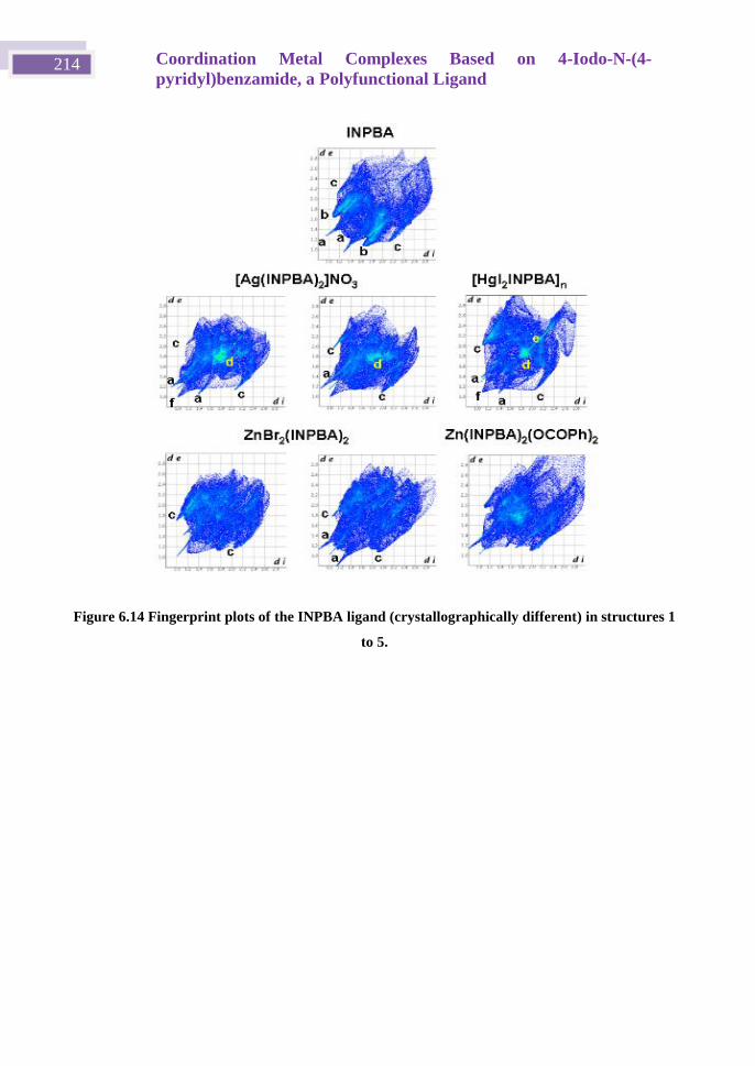
Coordination Metal Complexes Based on 4-Iodo-N-(4-
pyridyl)benzamide, a Polyfunctional Ligand 214
Figure 6.14 Fingerprint plots of the INPBA ligand (crystallographically different) in structures 1
to 5.
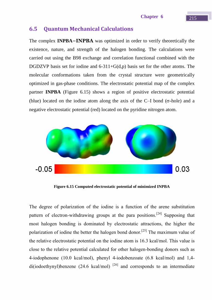
Chapter 6 215
6.5 Quantum Mechanical Calculations
The complex INPBA−INPBA was optimized in order to verify theoretically the
existence, nature, and strength of the halogen bonding. The calculations were
carried out using the B98 exchange and correlation functional combined with the
DGDZVP basis set for iodine and 6-311+G(d,p) basis set for the other atoms. The
molecular conformations taken from the crystal structure were geometrically
optimized in gas-phase conditions. The electrostatic potential map of the complex
partner INPBA (Figure 6.15) shows a region of positive electrostatic potential
(blue) located on the iodine atom along the axis of the C–I bond (-hole) and a
negative electrostatic potential (red) located on the pyridine nitrogen atom.
Figure 6.15 Computed electrostatic potential of minimized INPBA
The degree of polarization of the iodine is a function of the arene substitution
pattern of electron-withdrawing groups at the para positions.[24]
Supposing that
most halogen bonding is dominated by electrostatic attractions, the higher the
polarization of iodine the better the halogen bond donor.[25]
The maximum value of
the relative electrostatic potential on the iodine atom is 16.3 kcal/mol. This value is
close to the relative potential calculated for other halogen-bonding donors such as
4-iodophenone (10.0 kcal/mol), phenyl 4-iodobenzoate (6.8 kcal/mol) and 1,4-
di(iodoethynyl)benzene (24.6 kcal/mol) [26]
and corresponds to an intermediate
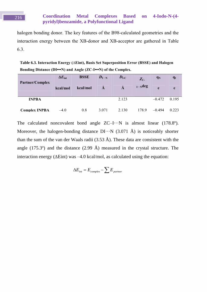
Coordination Metal Complexes Based on 4-Iodo-N-(4-
pyridyl)benzamide, a Polyfunctional Ligand 216
halogen bonding donor. The key features of the B98-calculated geometries and the
interaction energy between the XB-donor and XB-acceptor are gathered in Table
6.3.
The calculated noncovalent bond angle ZC–I···N is almost linear (178.8º).
Moreover, the halogen-bonding distance DI···N (3.071 Å) is noticeably shorter
than the sum of the van der Waals radii (3.53 Å). These data are consistent with the
angle (175.3º) and the distance (2.99 Å) measured in the crystal structure. The
interaction energy (Eint) was –4.0 kcal/mol, as calculated using the equation:
partnercomplexint EEE
Table 6.3. Interaction Energy (∆Eint), Basis Set Superposition Error (BSSE) and Halogen
Bonding Distance (DI•••N) and Angle (ZC-I•••N) of the Complex.
Partner/Complex
Eint
kcal/mol
BSSE
kcal/mol
DI···N
Å
DI-C
Å
ZC-
I···Ndeg
qN
e
qI
e
INPBA 2.123 –0.472 0.195
Complex INPBA –4.0 0.8 3.071 2.130 178.9 –0.494 0.223
Chapter 6 217
6.6 Conclusions
In this chapter we present the preparation and crystal structure of 4-iodo-N-(4-
pyridyl)benzamide (INPBA), three metal complexes, namely [Ag(INPBA)2]NO3,
[ZnBr2(INPBA)2], [Zn(OCOPh)2(INPBA)2], and the coordination polymer
[HgI2(INPBA)]n. The ligand INPBA shows a great ability to form different types
of interactions such as coordination, hydrogen and halogen bonds and - stacking.
This ability promotes increased dimensionality as well as the stability of the
structures in compounds 1–5. Furthermore, the interplay of coordination, halogen
bonding, hydrogen bonds and π···π interactions in these complexes also highlights
the complexity and challenge in programing the supramolecular assembly of metal
organic networks.
Coordination Metal Complexes Based on 4-Iodo-N-(4-
pyridyl)benzamide, a Polyfunctional Ligand 218
6.7 Experimental Section
4-Iodobenzoyl chloride, 4-aminopyridine, triethylamine, silver nitrate, zinc
bromide and mercury(II) iodide were used as received from commercial sources
(Sigma-Aldrich or Acros). 1H- and
13C-NMR spectra were recorded on a Bruker
Avance 300 spectrometer. Infrared (IR) spectra were recorded on an ATR-unit-
upgraded (Golden Gate) Bruker FT-IR Vertex 70 spectrophotometer. Mass spectra
were recorded on a VG Auto-spec instrument, with the ESI technique. C, H, and N
analyses were carried out with a Perkin-Elmer 2400 microanlyzer.
4-Iodo-N-(4-pyridyl)benzamide(INPBA).
A solution of 4-iodobenzoyl chloride (1.32 g, 5.0 mmol) and triethylamine (0.50 g,
5.0 mmol) in 50 mL of chloroform was cooled to 0 °C in an ice bath for 10 min. 4-
Aminopyridine (0.470 g, 5.0 mmol) was added slowly to the cold solution over a
period of 10 min. The reaction mixture was stirred at room temperature for 16 h.
The solution was concentrated and a white precipitate was obtained. The solid was
filtered off and washed several times with cold chloroform. Yield 1.33 g (82%). 1H
NMR spectrum (d6-DMSO, 300 MHz) from TMS: 7.63 (m, 3H, Bz), 7.78 (d, 2H,
Py), 7.95 (d, 2H, o-Bz), 8.47 (d, 2H, Py), 10.60 (s, NH). 13
C NMR spectrum (d6-
DMSO, 62.5 MHz): 114.70, 128.56, 129.15, 132.76, 134.96, 146.66, 150.97,
167.19. IR (ATR) max (neat) / cm–1
: 3332, 1660, 1587, 1502, 1477, 1413, 1330,
1282, 1210, 822, 748. High resolution positive ESI-MS (amu): Calcd. for M + H
324.9834 Found: 324.9827. Anal. Calcd. for C12H9IN2O: C 44.47, H 2.80, N 8.64.
Found: C 44.22, H 2.67, N 8.61.
Preparation of INPBA metal complexes
A solution of INPBA (32 mg, 0.10 mmol) in 10 mL of THF was added to 5 mL of
a methanolic solution of inorganic salt (0.1 mmol). The solution was allowed to
slowly evaporate with orbital stirring over a period of 48 h, during which time
colorless crystals formed.
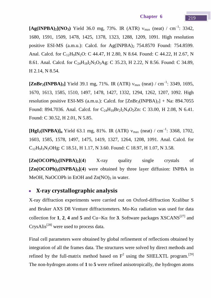
Chapter 6 219
[Ag(INPBA)2](NO3) Yield 36.0 mg, 73%. IR (ATR) max (neat) / cm–1
: 3342,
1680, 1591, 1509, 1478, 1425, 1378, 1323, 1288, 1209, 1091. High resolution
positive ESI-MS (a.m.u.): Calcd. for Ag(INPBA)2 754.8570 Found: 754.8599.
Anal. Calcd. for C12H9IN2O: C 44.47, H 2.80, N 8.64. Found: C 44.22, H 2.67, N
8.61. Anal. Calcd. for C24H18I2N5O5Ag: C 35.23, H 2.22, N 8.56. Found: C 34.89,
H 2.14, N 8.54.
[ZnBr2(INPBA)2] Yield 39.1 mg, 71%. IR (ATR) max (neat) / cm–1
: 3349, 1695,
1670, 1613, 1585, 1510, 1497, 1478, 1427, 1332, 1294, 1262, 1207, 1092. High
resolution positive ESI-MS (a.m.u.): Calcd. for [ZnBr2(INPBA)2] + Na: 894.7055
Found: 894.7036. Anal. Calcd. for C24H18Br2I2N4O2Zn: C 33.00, H 2.08, N 6.41.
Found: C 30.52, H 2.01, N 5.85.
[HgI2(INPBA)]n Yield 63.1 mg, 81%. IR (ATR) max (neat) / cm–1
: 3368, 1702,
1603, 1585, 1578, 1497, 1475, 1419, 1327, 1264, 1208, 1091. Anal. Calcd. for
C12H9I3N2OHg: C 18.51, H 1.17, N 3.60. Found: C 18.97, H 1.07, N 3.58.
[Zn(OCOPh)2(INPBA)2](4) X-ray quality single crystals of
[Zn(OCOPh)2(INPBA)2](4) were obtained by three layer diffusion: INPBA in
MeOH, NaOCOPh in EtOH and Zn(NO)3 in water.
X-ray crystallographic analysis
X-ray diffraction experiments were carried out on Oxford-diffraction Xcalibur S
and Bruker AXS D8 Venture diffractometers. Mo-K radiation was used for data
collection for 1, 2, 4 and 5 and Cu−K for 3. Software packages XSCANS[27]
and
CrysAlis[28]
were used to process data.
Final cell parameters were obtained by global refinement of reflections obtained by
integration of all the frames data. The structures were solved by direct methods and
refined by the full-matrix method based on F2 using the SHELXTL program.
[29]
The non-hydrogen atoms of 1 to 5 were refined anisotropically, the hydrogen atoms
Coordination Metal Complexes Based on 4-Iodo-N-(4-
pyridyl)benzamide, a Polyfunctional Ligand 220
of 2, 4, 5 were observed in difference electron density maps and refined
isotropically. Hydrogen atoms of 1 and 3 were included at idealized positions by
using a riding model and refined isotropically. The crystal parameters and basic
information relating data collection and structure refinement are summarized in
Table 6.4.
Hirshfeld Surface Analysis
Hirshfeld surfaces and the associated fingerprint plots were calculated using
CrystalExplorer,[23a]
which accepts a structure input file in the CIF format. Bond
lengths to hydrogen atoms were set to typical neutron values (C−H = 1.083 Å,
Table 6.4 Crystallographic data for INPBA, [Ag(INPBA)2]NO3(2), [ZnBr2(INPBA)2] (3),
[Zn(OCOPh)2(INPBA)2](4) and.[HgI2(INPBA)]n(5)
Compound INPBA 2 3(a) 4 5
Empirical formula C12H9IN2O C24H18N5O5I2Ag C24H18N4O2Br2I2Zn C38H28I2N4O6Zn C12H9HgI3N2O
Formula weight 324.11 818.10 873.41 955.81 778.50
Crystal System Monoclinic Triclinic Monoclinic Orthorhombic Monoclinic
a, Å 5.3119(3) 9.3872(5) 9.7184(2) 14.2615(6) 4.303(12)
b, Å 14.3087(6) 11.4744(4) 27.7576(6) 8.9996(3) 14.824(5)
c, Å 15.0594(9) 13.2529(6) 9.8707(2) 29.6078(13) 25.840(8)
, deg 107.591(4)
β, deg 90.017(5) 110.075(5) 91.040(2)
, deg 94.437(4)
V, Å3 1144.61(11) 1251.65(10) 2662.27(10) 3800.1(3) 1648.3(9)
T, K 248(2) 292(2) 100(2) 100(2) 293(2)
Space group P21/c Pī P21/c Pbcn P21/c
Z 4 2 4 4 4
μ(Mo K), mm–1 2.777 3.318 23.252 2.321 14.950
Θ range, deg 1.96 to 28.32 1.75 to 26.37 3.18 to 74.29 2.68 to 26.37 3.15 to 25.00
Refl. collected 8308 8687 20071 40876 5264
Uniq reflect / Rint 2604 / 0.0384 5123 / 0.0239 5330 /0.0612 3879 / 0.0326 2884 / 0.0340
R1/wR2 (I>2σ) 0.0376 / 0.0655 0.0295 / 0.0638 0.0500 / 0.1287 0.0315 / 0.0726 0.0420 / 0.0778
R1/wR2 (all data) 0.0529 / 0.0703 0.0336 / 0.0677 0.0521 / 0.1304 0.0382 / 0.0764 0.0666 / 0.0872
Max. shift/esd 0.001 0.009 0.001 0.001 0.004
Residual ρ/e Å–3
0.669 and –0.633 1.181 and -0.975 1.895 and -2.123 2.016 and -1.927 1.161 and –1.361
Chapter 6 221
N−H = 1.009 Å, O−H = 0.983 Å). The distance from the Hirshfeld surface to the
nearest atoms outside and inside the surface are characterized by the quantities de
and di, respectively, and the normalized contact distance based on these, dnorm = (di
– rivdW
)/ rivdW
+( de – revdW
)/ revdW
, with rivdW
and revdW
are the van der Waals radii of
the atoms. The 2D histograms, fingerprints, plot distance external to the surface
(de) versus distance internal to the surface (di): is the distance from the surface to
the nearest atom in the molecule itself.
Computational Methods.
Quantum chemical calculations were performed using the Gaussian 09[30]
suite of
programs. Geometry optimizations were carried out in the gas phase with the
B98[31]
method, employing the 6-311G+(d,p)[32]
basis set for all atoms except
iodine, for which the DGDZVP[33]
basis set was used. Geometry optimizations
were carried out without constraints, using the default convergence criteria for the
Gaussian software. The natural bond orbital (NBO) analysis[34]
using the NBO
module contained in the Gaussian 09 program was performed on the basis of the
minimized structures in order to calculate the NBO charges. The resulting
electronic energies of interaction were corrected for scale (0.9884),[35]
zero point
differences and for basis set superposition errors.
Coordination Metal Complexes Based on 4-Iodo-N-(4-
pyridyl)benzamide, a Polyfunctional Ligand 222
6.8 Bibliography
[1] M. D. Allendorf and V. Stavila, CrystEngComm 2015, 17, 229-246.
[2] S. Q. Liu, T. Kuroda-Sowa, H. Konaka, Y. Suenaga, M. Maekawa, T. Mizutani, G. L. Ning and
M. Munakata, Inorg. Chem. 2005, 44, 1031-1036.
[3] M. D. Allendorf, C. A. Bauer, R. K. Bhakta and R. J. Houk, Chem Soc Rev 2009, 38, 1330-1352.
[4] a) O. M. Yaghi, M. O’Keeffe, N. . Ockwig, H. K. Chae, M. Eddaoudi and J. Kim, Nature
2003, 423, 705; b) J. L. C. Rowsell and O. M. Yaghi, J. Am. Chem. Soc. 2006, 128, 1304-1315; c)
K. Sumida, D. L. Rogow, J. A. Mason, T. M. McDonald, E. D. Bloch, Z. R. Herm, T.-H. Bae and J.
R. Long, Chem. Rev. 2012, 112, 724-781; d) M. P. Suh, H. J. Park, T. K. Prasad and D.-W. Lim,
Chem. Rev. 2012, 112, 782-835.
[5] C. B. Aakeröy, A. M. Beatty and D. S. Leinen, Angew. Chem. Int. Ed. 1999, 38, 1815-1819.
[6] a) L. Brammer, G. M. Espallargas and S. Libri, CrystEngComm 2008, 10, 1712-1727; b) R.
Bertani, P. Sgarbossa, A. Venzo, F. Lelj, M. Amati, G. Resnati, T. Pilati, P. Metrangolo and G.
Terraneo, Coord. Chem. Rev. 2010, 254, 677; c) R. Bertani, P. Sgarbossa, A. Venzo, F. Lelj, M.
Amati, G. Resnati, T. Pilati, P. Metrangolo and G. Terraneo, Coord. Chem. Rev. 2010, 254, -
d) . . Troff, T. M kel , . Topic , A. Valkonen, K. Raatikainen and K. Rissanen, Eur. J.
Org. Chem. 2013, 2013, 1617; e) B. Li, S.-Q. Zang, L.-Y. Wang and T. C. W. Mak, Coord. Chem.
Rev. 2016, 308, 1-21.
[7] S. Graus in Sintones supramoleculares clásicos: nuevas arquitecturas cristalinas y
determinación de estructuras absolutas, Vol. Thesis Zaragoza, University of Zaragoza, 2015.
[8] a) M. D. Ward, Dalton Trans. 2010, 39, 8851-8867; b) J. E. Ormond-Prout, P. Smart and L.
Brammer, Cryst. Growth Des. 2012, 12, 205-216.
[9] a) K. Biradha, C.-Y. Su and J. J. Vittal, Cryst. Growth Des. 2011, 11, 875-886; b) G. R.
Desiraju, J. J. Vittal and A. Ramanan, Crystal Engineering: A Textbook, World Scientific Pub. Co.
Inc. 2011.
[10] a) H. R. Khavasi and A. A. Tahrani, CrystEngComm 2013, 15, 5799-5812; b) H. R. Khavasi
and A. A. Tehrani, Inorg. Chem. 2013, 52, 2891-2905.
[11] C. B. Aakeroy, N. Schultheiss, J. Desper and C. Moore, CrystEngComm 2007, 9, 421-426.
[12] H. R. Khavasi, M. Hosseini, A. A. Tehrani and S. Naderi, CrystEngComm 2014, 16, 4546.
[13] A. Collas, R. De Borger, T. Amanova and F. Blockhuys, CrystEngComm 2011, 13, 702-710.
[14] J. C. Noveron, M. S. Lah, R. E. Del Sesto, A. M. Arif, J. S. Miller and P. J. Stang, J. Am.
Chem. Soc. 2002, 124, 6613-6625.
[15] H. R. Khavasi, M. Hosseini, A. A. Tehrani and S. Naderi, CrystEngComm 2014, 16, 4546-
4553.
[16] J. C. Noveron, A. M. Arif and P. J. Stang, Chem. Mat. 2003, 15, 372-374.
[17] H. J. Bohórquez and R. J. Boyd, Chem. Phys. Lett. 2009, 480, 127-131.
[18] a) S. Nag, K. Banerjee and D. Datta, New J. Chem. 2007, 31, 832-834; b) S.-Z. Hu, Z.-H. Zhou
and B. E. Robertson, Z. Kristallogr. 2009, 224, 375-383.
[19] a) C. Hu, I. Kalf and U. Englert, CrystEngComm 2007, 9, 603-610; b) W.-T. Chen, M.-S.
Wang, X. Liu, G.-C. Guo and J.-S. Huang, Cryst. Growth Des. 2006, 6, 2289-2300; c) Q.-Y. Du, J.-
H. Qin and H.-X. Wu, Chin. J. Struct. Chem. 2007, 26, 817-821.
[20] H.-P. Zhou, J.-H. Yin, L.-X. Zheng, P. Wang, F.-Y. Hao, W.-Q. Geng, X.-P. Gan, G.-Y. Xu, J.-
Y. Wu, Y.-P. Tian, X.-T. Tao, M.-H. Jiang and Y.-H. Kan, Cryst. Growth Des. 2009, 9, 3789-3798.
[21] Y.-H. Shen, J.-G. Liu and D.-J. Xu, Acta Cryst. E: Structur. Rep. Online 2005, 61, m1880-
m1882.
[22] Y. H. Shen, J. G. Liu and D. J. Xu, Acta Crystallogr., Sect. E: Struc. Rep. Online 2005, 61,
M1880-M1882.
[23] a) S. K. Wolff, D. J. Grimwood, J. J. McKinnon, M. J. Turner, D. Jayatilaka and M. A.
Spackman in CrystalExplorer Vol. (Ed. CrystalExplorer), University of Western Australia, 2012; b)
M. A. Spackman and D. Jayatilaka, CrystEngComm 2009, 11, 19-32.
Chapter 6 223
[24] C. B. Aakeroey, M. Baldrighi, J. Desper, P. Metrangolo and G. Resnati, Chem. Eur. J. 2013,
19, 16240-16247.
[25] F. C. Pigge, V. R. Vangala, D. C. Swenson and N. P. Rath, Cryst. Growth Des. 2010, 10,
224−231.
[26] L. Gonzalez, N. Gimeno, M. R. Maria Tejedor, V. Polo, M. B. Ros, S. Uriel and J. L. Serrano,
Chem. Mat. 2013, 25, 4503-4510.
[27] XSCANS in Vol. Madison, Wisconsin, USA., 1994.
[28] CrysAlis and CCD in Oxford Diffraction Ltd, Vol. Abingdon, England, 2006.
[29] G. M. Sheldrick, Acta Cryst. A 2008, 64, 112-122.
[30] M. J. Frisch, G. W. Trucks, H. B. Schlegel, G. E. Scuseria, M. A. Robb, J. R. Cheeseman, G.
Scalmani, V. Barone, B. Mennucci, G. A. Petersson, H. Nakatsuji, M. Caricato, X. Li, H. P.
Hratchian, A. F. Izmaylov, J. Bloino, G. Zheng, J. L. Sonnenberg, M. Hada, M. Ehara, K. Toyota,
R. Fukuda, J. Hasegawa, M. Ishida, T. Nakajima, Y. Honda, O. Kitao, H. Nakai, T. Vreven, J.
Montgomery, J. A., J. E. Peralta, F. Ogliaro, M. Bearpark, J. J. Heyd, E. Brothers, K. N. Kudin, V.
N. Staroverov, R. Kobayashi, J. Normand, K. Raghavachari, A. Rendell, J. C. Burant, S. S. Iyengar,
J. Tomasi, M. Cossi, N. Rega, J. M. Millam, M. Klene, J. E. Knox, J. B. Cross, V. Bakken, C.
Adamo, J. Jaramillo, R. Gomperts, R. E. Stratmann, O. Yazyev, A. J. Austin, R. Cammi, C. Pomelli,
J. W. Ochterski, R. L. Martin, K. Morokuma, V. G. Zakrzewski, G. A. Voth, P. Salvador, J. J.
Dannenberg, S. Dapprich, A. D. Daniels, Ö. Farkas, J. B. Foresman, J. V. Ortiz, J. Cioslowski and
D. J. Fox in Gaussian 09, Vol. Gaussian Inc., Wallingford CT, 2009.
[31] a) P. M. W. Gill, Mol. Phys. 1996, 89, 433-445; b) J. P. Perdew, K. Burke and M. Ernzerhof,
Phys. Rev. Lett. 1996, 77, 3865-3868; c) M. G. Chudzinski and M. S. Taylor, J. Org. Chem. 2012,
77, 3483-3491.
[32] W. J. Hehre, L. Radom, S. P. V. R. and J. A. Pople in Ab initio Molecular Orbital Theory, Vol.
Wiley, New York, 1986.
[33] N. Godbout, D. R. Salahub, J. Andzelm and E. Wimmer, Can. J. Chem. 1992, 70, 560-571.
[34] A. E. Reed, L. A. Curtiss and F. Weinhold, Chem. Rev. 1988, 88, 899-926.
[35] J. P. Merrick, D. Moran and L. Radom, J. Phys. Chem. A 2007, 111, 11683-11700.

Chapter 7 Conclusions

Chapter 7 227
General Conclusions
The haloethynyl group form strong halogen bond interactions comparable to the
well known Iodopentafluorobenzene moieties. The ethynyl group acts as a good
electron withdrawing increasing the sigma hole in the halogen, mainly in the Iodine
atom.
Haloethynyl derivatives behave as excellent building blocks in supramolecular
chemistry, thanks to the halogen bond interaction and the anisotropy of the bond.
Furthermore, haloethynyls groups act as heteroditopic tectons.
Halogen bond is useful in different applications like liquid crystals or porous
materials, opening new possibilities in organic chemistry materials.
Conclusions 228
Capítulo 2
Se han sintetizado y caracterizado diferentes alquinos yodados. Además se ha
realizado un estudio comparativo de las estructuras cristalinas de estos alquinos
yodados con sus precursores con el grupo etinilo.
Los estudios realizados permiten concluir que cuando las moléculas son rígidas y
planas tanto los derivados iodados como sus precursores pueden dar lugar
organizaciones supramoleculares isoestructurales. Las diferencias entre las
estructuras de los derivados alquínicos y sus yododerivados homólogos están
relacionadas con el número de grupos etinilos y su proximidad.
Por otro lado, las moléculas flexibles no llegan a presentar isoestructuralismo. En
estos derivados la organización supramolecular no está gobernada únicamente por
la interacción más fuerte, por ejemplo el enlace de halógeno o el enlace de
hidrógeno (Csp−I···Y and Csp−H···Y), cobrando mayor importancia en el
empaquetamiento final de la estructura cristalina otras interacciones débiles como
Csp2−H···Y.
Capítulo 3
Los derivados yodados de la base de Tröger “2,8-diiodo-4,10-dimethyl-6H,12H-
5,11-methano-dibenzodiazocine” (rac−1) y (5S,11S)−1) quiral son
tetraheterotópicos y autocomplementarios mediante enlaces de halógeno, siendo
adecuados para obtener tanto de estructuras supramoleculares tipo clatrato como
materiales cristalinos compactos.
Además, se han obtenido estructuras porosas tipo diamante cuando rac−1 es
cristalizado a partir de una solución de diclorometano. Las arquitecturas
supramoleculares de las estructuras compactas rac−1 y (5S,11S)-1 presentan
algunas similitudes aunque el enlace de halógeno juegue en diferentes roles en cada
estructura. Así, en rac−1 son observadas las interacciones de enlace de halógeno
Chapter 7 229
N···I y I···I, mientras que en (5S,11S)-1 solo esta presente la interacción I···I.
Estas son las primeras estructuras de derivados yodados de la base de Tröger que
presentan interacciones tipo I···I.
Por otro lado, el derivado de base de Tröger “2,8-diiodoethynyl-4,10-dimethyl-
6H,12H-5,11-methanodibenzodiazocine” (rac−2) cristaliza en el grupo espacial
monoclinico P21/c mostrando canales nanométricos los cuales representan el 20%
de volumen de la celda. Estos canales están ocupados por moléculas de disolvente.
Los dos grupos yodoetinilos se comportan como fuertes dadores de enlaces de
halógeno I···N y I···π(Ar). Estas interacciones forman unidades dímeras formadas
por los dos enantiómeros (5S,11S)-2 y (5R,11R)-2 que juegan un papel
fundamental en la obtención de organizaciones cristalinas nanoporosas.
Capítulo 4
En este capítulo se han descrito once estructuras basadas en complejos de enlace de
halógeno a partir de “bis(haloethynyl)benzene” con moléculas cuyos aceptores de
enlace de halógeno eran: nitrógeno, oxígeno y bases halogenadas. Todo ello
además del análisis de las superficies de Hirshfeld y los cálculos de química
cuántica nos permite establecer que pBIEB, pBBrEB y mBIEB son buenos
dadores de XB, haciendo de ellos una herramienta muy útil en el diseño de
estructuras supramoleculares.
La distancia del enlace de halógeno Csp−I···N depende de la hibridación del átomo
de nitrógeno y decrece siguiendo la tendencia desde sp a sp3 a sp
2. Además, la
distribución electrónica del grupo haloetinil muestra un área nuecleofilica cilíndrica
alrededor del triple enlace y del átomo de halógeno lo que permite la formación de
enlaces de hidrógeno del tipo Csp2−H···X y Csp2−H···(alkyne) con hidrógenos del
anillo aromatico, que impide la formación de organizaciones tipo espiga. La
energía de estabilización de estas estructuras supramoleculares varía entre 2.9 a 5.7
kcal mol-1
. A pesar de ser interacciones débiles, sus efectos en la estructura
Conclusions 230
cristalina y el empaquetamiento es relevante y en combinación con los enlaces de
halógeno son herramientas muy útiles para el aumento de la dimensionalidad en los
cocristales teniendo un gran interés en el desarrollo de materiales orgánicos.
El ITC es una herramienta útil para estudiar las interacciones de los enlaces
halógenos, ayudando a entender la esfera de coordinación, en este caso, del
bromuro.
Capítulo 5
Los derivados de yodoetinilbenceno han demostrado ser buenos dadores de enlaces
de halógeno. La unión de un átomo de yodo a un átomo de carbono con hibridación
sp conduce a la formación de interacciones no covalentes con derivados de piridina
fuertes (ΔEint = -10 kcal / mol) e interacciones un poco más débiles con los
benzonitrilos (ΔEint = -7,5 kcal / mol).
El pBIEB al ser una molécula lineal forma complejos de enlace de halógeno con
aceptores basados en piridina que llevan uno o dos anillos aromáticos para dar
complejos que muestran fases calamiticas ordenadas (SmB y CrG) en amplios
intervalos de temperatura. Por otra parte, el mBIEB al ser una molécula angular
forma complejos de enlace de halógeno con derivados de piridina que contienen
tres anillos aromáticos para dar complejos que muestran fases de tipo banana.
Además, el 1,3,5-TIEB tipo disco forma complejos de enlace de halógeno con
derivados de piridina con aminas como conectores. Los estudios XRD, ITC,
Raman y de modelización apoyan los resultados experimentales y también explican
las interacciones más débiles de estos dadores de halógeno con un aceptor basado
en benzonitrilo. Se encontró experimentalmente que esta interacción más débil
impide la formación de complejos homogéneos de enlace de halógeno tras la
fusión.
Chapter 7 231
Capítulo 6
En este capítulo se ha presentado la preparación y síntesis de la estructura cristalina
de “4-iodo-N-(4-pyridyl)benzamide” (INPBA), tres complejos metálicos,
[Ag(INPBA)2]NO3, [ZnBr2(INPBA)2], [Zn(OCOPh)2(INPBA)2], y un polímero
de coordinación [HgI2(INPBA)]n. El ligando INPBA da lugar a diferentes tipos de
interacciones tales como: coordinación, enlaces de hidrógeno y de halógeno e
interacciones de apilamiento -. Esto favorece el aumento de la dimensionalidad
así como la estabilidad de la estructura en los compuestos. Además, la interacción
de la coordinación, el enlace de halógeno, los enlaces de hidrógeno y las
interacciones π···π en estos complejos también pone de manifiesto la complejidad
y desafío en el diseño de la organización supramolecular de redes orgánicas
metálicas.