Embed Size (px)
Citation preview
User Guide

Trademark NoticesMicrosoft and Windows are registered trademarks of Microsoft Corporation. Other product names mentioned herein may be trademarks and/or registered trademarks of their respective owners.Second Edition, June 25, 2015 Copyright © 2013-2015. Comtrol Corporation. All Rights Reserved.Comtrol Corporation makes no representations or warranties with regard to the contents of this document or to the suitability of the Comtrol product for any particular purpose. Specifications subject to change without notice. Some software or features may not be available at the time of publication. Contact your reseller for current product information.
Document Number: 2000601 Rev. B

Table of Contents
Chapter 1. Introduction........................................................................................................51.1. Installation and Configuration Overview ........................................................................................ 51.2. Locating the Latest Software and Documentation ........................................................................ 6
Chapter 2. Hardware Installation ......................................................................................92.1. Connecting to the Network.................................................................................................................. 92.2. Connecting the Power........................................................................................................................... 9
Chapter 3. Initial Configuration.......................................................................................113.1. Network Configuration Overview.................................................................................................... 113.2. Using the Web Interface to Program the Network....................................................................... 123.3. Setting User Accounts and Passwords ............................................................................................ 143.4. Configuring Miscellaneous Settings ................................................................................................ 17
Chapter 4. Connecting Devices .........................................................................................194.1. Connecting to IO-Link Ports.............................................................................................................. 19
4.1.1. Tips When Connecting Devices to the IOLM DR-8-EIP............................................................... 204.1.2. Connecting IO-Link Devices .......................................................................................................... 204.1.3. Connecting Digital Input Devices to IO-Link Ports ..................................................................... 20
4.2. Connecting Digital IO Ports .............................................................................................................. 214.2.1. Connecting to DI ............................................................................................................................. 214.2.2. Connecting to DIO .......................................................................................................................... 22
Chapter 5. Updating Images and Applications .............................................................235.1. Images and Application Subassemblies Overview ....................................................................... 23
5.1.1. Images ............................................................................................................................................. 245.1.2. Application Subassemblies............................................................................................................. 24
5.2. Using the Web Interface to Update Software ................................................................................ 255.2.1. Updating Images............................................................................................................................. 255.2.2. Updating Application Subassemblies ............................................................................................ 26
Chapter 6. IO-Link Port Configuration...........................................................................276.1. Preparing for Port Configuration .................................................................................................... 276.2. IO-Link Configuration Page .............................................................................................................. 29
6.2.1. Editing IO-Link Settings................................................................................................................ 306.2.2. IO-Link Settings Parameters......................................................................................................... 31
6.3. EtherNet/IP Settings Configuration Page ...................................................................................... 346.3.1. Editing EtherNet/IP Settings ........................................................................................................ 356.3.2. EtherNet/IP Settings Parameters ................................................................................................. 36
6.4. Modbus/TCP Settings Configuration Page..................................................................................... 416.4.1. Editing Modbus/TCP Settings........................................................................................................ 426.4.2. Modbus/TCP Settings Parameters................................................................................................. 43
IO-Link Master DR-EIP User Guide: 2000601 Rev. B Table of Contents - 3

Table of Contents
Chapter 7. Dedicated Digital I/O Port Configuration..................................................477.1. Editing Digital I/O Settings................................................................................................................ 487.2. Digital I/O Setting Parameters.......................................................................................................... 49
Chapter 8. Loading and Managing IODD Files .............................................................518.1. IO-Link Device Description Files Page ........................................................................................... 51
8.1.1. Preparing IODD Files to Upload ................................................................................................... 528.1.2. Uploading IODD Zip Files.............................................................................................................. 538.1.3. Uploading xml Files or Supporting Files ...................................................................................... 548.1.4. Viewing and Saving IODD Files .................................................................................................... 558.1.5. Deleting IODD Files ....................................................................................................................... 56
8.2. IO-Link Device Configuration Summary Page.............................................................................. 57
Chapter 9. Configuring IO-Link Devices ........................................................................599.1. Port Pages Overview ........................................................................................................................... 599.2. Editing Parameters - IO-Link Device - Port Table ....................................................................... 609.3. Resetting IO-Link Device Parameters to Factory Defaults ....................................................... 629.4. Editing Parameters - IO-Link Device ISDU Interface - Port ..................................................... 63
Chapter 10. Utilizing IOLM DR-8-EIP Features............................................................6710.1. Data Storage ........................................................................................................................................ 67
10.1.1. Uploading Data Storage to the IOLM DR-8-EIP ........................................................................ 6710.1.2. Downloading Data Storage to the IO-Link Device ..................................................................... 6810.1.3. Automatic Device Configuration.................................................................................................. 6810.1.4. Automatic Device Configuration Backup .................................................................................... 70
10.2. Device Validation ............................................................................................................................... 7110.3. Data Validation................................................................................................................................... 7210.4. IOLM DR-8-EIP Configuration Files.............................................................................................. 73
10.4.1. Saving Configuration Files........................................................................................................... 7310.4.2. Loading Configuration Files ........................................................................................................ 74
10.5. Using the Menu Bar Hover Shows Submenu Option ................................................................. 75
Chapter 11. Using the Diagnostics Pages .......................................................................7711.1. IO-Link Port Diagnostics.................................................................................................................. 7811.2. Digital I/O Diagnostics ...................................................................................................................... 8211.3. EtherNet/IP Diagnostics ................................................................................................................... 8311.4. Modbus/TCP Diagnostics.................................................................................................................. 87
Chapter 12. Troubleshooting and Technical Support .................................................9112.1. Troubleshooting.................................................................................................................................. 9112.2. IOLM DR-8-EIP LEDs ........................................................................................................................ 9212.3. Contacting Technical Support ........................................................................................................ 9312.4. Using Log Files.................................................................................................................................... 94
12.4.1. View a Log File ............................................................................................................................. 9412.4.2. Clear a Log File............................................................................................................................. 9512.4.3. Export a Log File .......................................................................................................................... 95
4 - Table of Contents IO-Link Master DR-EIP User Guide: 2000601 Rev. B

Chapter 1. Introduction
This document provides installation, configuration, and embedded web interface information for the Comtrol IO-Link Master (IOLM DR-8-EIP). The web interface provides a platform so that you can easily configure, review diagnostic pages, and access advanced features, such as the ability to:• Upload the latest IOLM DR-8-EIP images or applications• Set up user accounts with different user levels and passwords• Load IODD files and configure IO-Link device parameters• Implement manual or automatic data storage (upload or download)• Implement device and/or data validation
1.1. Installation and Configuration Overview
The IOLM DR-8-EIP installation includes the following procedures.1. Connect the power and Ethernet cable (Page 9).2. Configure the IP address using the embedded web interface or PortVision DX (Page 11).3. Connect the IO-Link and digital I/O devices (Page 19).4. Use the web interface to configure the following:
a. IOLM DR-8-EIP ports for your environment using the web interface (Page 27):• IO-Link settings, such as the Port Mode, which by default is set to IO-Link but depending on the
device, you may need to set it to Digital In or Digital Out.• EtherNet/IP settings• Modbus/TCP settings
b. If necessary, configure the dedicated digital I/O ports (Page 47).c. If desired, upload the appropriate IODD files for your IO-Link devices (Page 51) for IO-Link device
configuration.d. If desired, configure the IO-Link device parameters (Page 59).e. If desired, implement IOLM DR-8-EIP features or options (Page 67), such as:
• Data storage, automatic or manual - upload or download• Device validation• Data validation• IOLM DR-8-EIP configuration files (save and load)
f. Use the Diagnostic pages to monitor or troubleshoot your devices.5. If desired, connect to a PLC or HMI/SCADA (depending on your protocol):
• EtherNet/IP, which is discussed in detail in the IO-Link Master EtherNet/IP Reference Manual- .If appropriate, unzip and import the RSLogix 5000 program examples. - If appropriate, connect SLC, PLC-5, or MicroLogix PLCs.- Add EDS files to RSLinx for normal IOLM DR-8-EIP-to-PLC communications
• Modbus/TCP: connect PLCs or HMI/ SCADA devices, which is discussed in detail in the IO-Link Master Modbus/TCP Reference Manual
IO-Link Master DR-EIP User Guide: 2000601 Rev. B Chapter 1. Introduction - 5
Locating the Latest Software and Documentation
1.2. Locating the Latest Software and Documentation
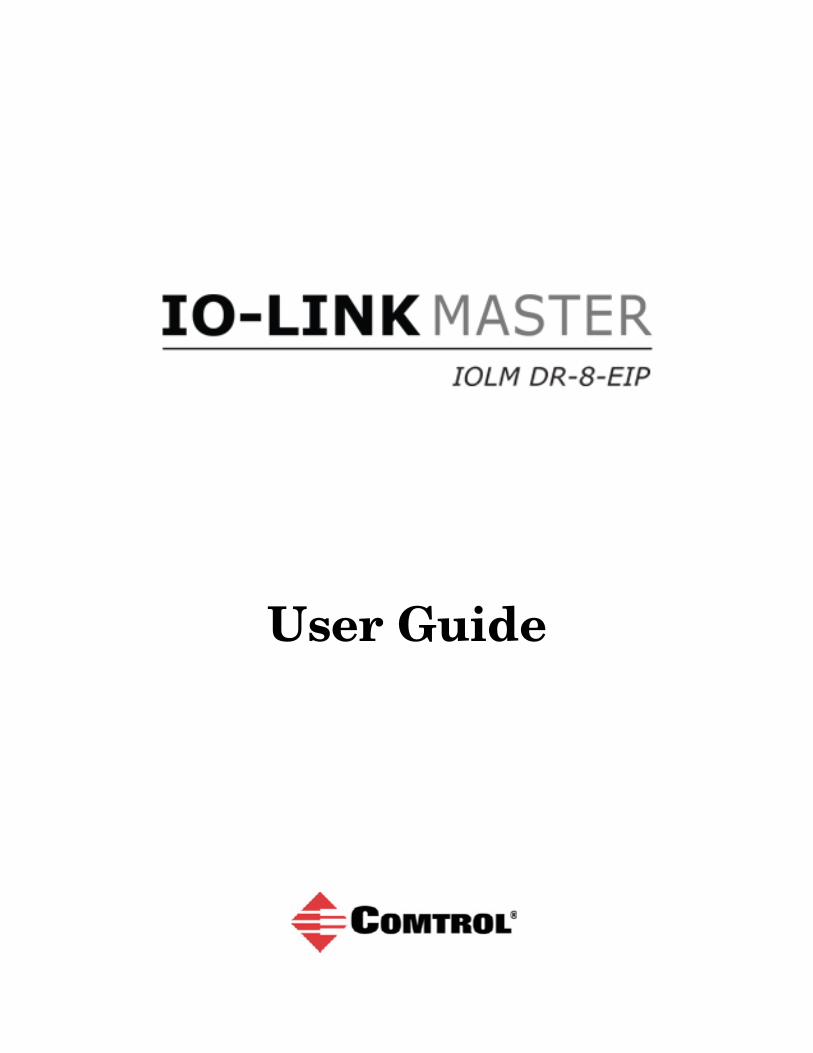
You can use the links in the following tables to locate the latest images, utilities, and documentation. For information about images and updating the IOLM DR-8-EIP, see Chapter 5. Updating Images and Applications on Page 23.
Note: The Application Base image contains all of the latest applications. If a feature enhancement or bug fix is required, the application will be available on the Download page.
Latest Images
Application Base
FPGA
U-Boot Bootloader
System uImage (Primary/Backup)
Latest Configuration Utility
PortVision DX (Windows XP through Windows 8.1)
PortVision DX automatically detects Comtrol Ethernet attached products physically attached to the local network segment so that you can quickly configure the network address, upload firmware, access IOLM DR-8-EIP embedded web interface, and download the latest product documentation. PortVision DX also provides these features:• Telnet/SSH interface• PuTTY• Ability to save and load IOLM DR-8-EIP configuration files• Save Device Diagnostics Data, in the event you have a support issue• LED Tracker featureNote: PortVision DX procedures are not discussed in this document. If you require
information about using PortVision DX, you can use the help system or the PortVision DX User Guide.
Product Documentation Description Web
IO-Link Master DR-EIP User Guide
The latest User Guide that matches the latest released application base on the ftp site.
IO-Link Master EtherNet/IP Reference Manual
The EIP Reference Manual discusses the following information:• EtherNet/IP interface• Functionality descriptions• EtherNet/IP CIP Object Definitions• EtherNet/IP Settings web page• ControlLogix Family - example PLC programs• SLC/PLC-5/MicroLogix interface• EDS files
6 - Chapter 1. Introduction IO-Link Master DR-EIP User Guide: 2000601 Rev. B

Locating the Latest Software and Documentation
IO-Link Master Modbus/TCP Reference Manual
The Modbus/TCP Reference Manual discusses the following information:• Modbus/TCP interface• Functionality descriptions• Modbus/TCP Settings web page
PortVision DX User Guide
This discusses the following topics:• Installing PortVision DX• User interface overview• Managing the view• Network configuration • Firmware• Software Settings• Accessing Comtrol configuration web pages• Configuration files• Telnet | SSH sessions• Accessing other applications• Changing PortVision DX options• Logging events
Product Documentation Description Web
IO-Link Master DR-EIP User Guide: 2000601 Rev. B Chapter 1. Introduction - 7

Locating the Latest Software and Documentation
8 - Chapter 1. Introduction IO-Link Master DR-EIP User Guide: 2000601 Rev. B

Chapter 2. Hardware Installation
Note: The IOLM DR-8-EIP must be installed in a suitable fire, electrical, mechanical enclosure.
2.1. Connecting to the Network
The IOLM DR-8-EIP provides two Fast Ethernet (10/100BASE-TX) standard RJ45 connections. You can use this procedure to connect the IOLM DR-8-EIP to the network.1. Securely connect one end of the RJ45 Ethernet cable to either Ethernet port.2. Connect the other end to the network.3. Optionally, use the other Ethernet port to daisy-chain to another Ethernet device.
2.2. Connecting the Power
The IOLM DR-8-EIP provides two redundant power inputs with screw terminals on the top and bottom of the unit. Note: Use either power terminal (top or bottom) but DO NOT use both to supply power
to the IOLM DR-8-EIP.
You can use this procedure to connect the IOLM DR-8-EIP to a power supply.Note: Power should be disconnected from the power supply before connecting it to the IOLM DR-8-EIP.
Otherwise, your screwdriver blade can inadvertently short your terminal connections to the grounded enclosure.
1. Insert positive and negative wires (12-24AWG) into the V+ and V- contacts. 2. Tighten the wire-clamp screws to prevent the wires from coming loose.
Signal Description
V- 24VDC Power Supply Return
V- 24VDC Power Supply Return
V+ Primary +24VDC Supply
V+ Secondary +24VDC Supply
Power Requirements Values
Voltage Input Range 18 to 30VDCInput Power 24VDC @4AOutput power 24VDC @ 200mA†† The total supply of current for all connected IO-Link devices.
IO-Link Master DR-EIP User Guide: 2000601 Rev. B Chapter 2. Hardware Installation - 9

Connecting the Power
3. Apply the power and verify that the following LEDs are lit indicating that you are ready to attach your IO-Link or digital I/O devices.• PWR - green lit LED indicates the IOLM DR-8-EIP is receiving power.• MS, first the flashing green and red LEDs display that it is in self-test mode.
- The green LED is flashing to indicate that the IOLM DR-8-EIP is in standby mode.- The green LED is lit to indicate that the IOLM DR-8-EIP is operational.
• NS, first it flashes green and red indicating that it is in self-test mode. - Off indicates there is no IP address.- Steady red indicates a duplicate IP address on the network.
• LINK should be lit (green) to indicate a valid network connection.• ACT blinks if there is network traffic between the IOLM DR-8-EIP and the network.• Port LEDs should display in this manner if there is no device attached:
- IO-Link port LED should be flashing green indicating that it is searching for an IO-Link device.
- Digital input should be off to indicate that there is no device attached to the port.
If the LEDs indicate that you are ready to attach devices, go to Chapter 4. Connecting Devices on Page 19. If the LEDs do not meet the above conditions, you can refer to the IOLM DR-8-EIP LEDs table on Page 92 in the Troubleshooting and Technical Support chapter.
10 - Chapter 2. Hardware Installation IO-Link Master DR-EIP User Guide: 2000601 Rev. B
Chapter 3. Initial Configuration
The following topics are discussed in this chapter.• Network Configuration Overview• Using the Web Interface to Program the Network on Page 12• Setting User Accounts and Passwords on Page 14• Configuring Miscellaneous Settings on Page 17
3.1. Network Configuration Overview
You can use one of the following methods to configure the IP address.• Web interface (Page 12)
Note: If you do not use PortVision DX to configure the IP address, you will need to change your PC or laptop address to the same subnet as the IOLM DR-8-EIP.
The IOLM DR-8-EIP default IP address is: 192.168.1.250 and the Subnet Mask is: 255.255.255.0.Use the Advanced | Network page, if you want to configure the following:- Host name- DNS servers- Syslog Server IP/Host name- Syslog Port- SSH Server EnableNote: You can use PortVision DX to configure the IP address information (Properties) and then use the
web interface to configure the options not configurable in PortVision DX.• PortVision DX automatically detects Comtrol Ethernet attached products physically attached to the
local network segment so that you can quickly configure the network address, upload firmware, access the IOLM DR-8-EIP web interface, and download the latest product documentation.PortVision DX also provides these features:- Telnet/SSH interface- PuTTY- Ability to save and load IOLM DR-8-EIP configuration files- Save Device Diagnostics Data, which can be sent to Comtrol in the event you have a support issue- LED Tracker feature to identify the IOLM DR-8-EIP with the LEDs flashingYou can download PortVision DX from the Comtrol ftp site using the ftp interface or the direct path at; ftp://ftp.comtrol.com/IO_Link_Master/PortVision_DX. If you need information about using PortVision DX, you can use the PortVision DX help system or download the PortVision DX User Guide.
IO-Link Master DR-EIP User Guide: 2000601 Rev. B Chapter 3. Initial Configuration - 11

Using the Web Interface to Program the Network
3.2. Using the Web Interface to Program the Network
This subsection discusses using the web interface to configure the IP address. The default IP address is 192.168.1.250 and the Subnet Mask is: 255.255.255.0. The IOLM DR-8-EIP is shipped from the factory with the Admin account enabled without a password. You can configure the Admin, Operator, and User passwords.1. Open the IOLM DR-8-EIP web interface using one of these method:
• Open your browser and enter the IP address of the IOLM DR-8-EIP.• From PortVision DX, highlight the IOLM DR-8-EIP and click the Webpage button or right-click the
IOLM DR-8-EIP in the Device List pane (lower pane) and click Webpage.2. Click Configuration | NETWORK.3. Click the EDIT button.
Note: This image shows the IOLM DR-8-EIP, which provides dedicated Digital I/O ports and a Configuration page.
12 - Chapter 3. Initial Configuration IO-Link Master DR-EIP User Guide: 2000601 Rev. B

Using the Web Interface to Program the Network
4. Optionally, change the host name to identify this IOLM DR-8-EIP.5. Select the IP type, Static or DHCP.
• If using a static IP address, enter the static IP address, subnet mask and IP gateway address.• If using DNS:
- Enter the DNS primary server IP address.- Optionally, enter the DNS secondary server IP address.
6. If you want the IOLM DR-8-EIP to send syslog messages to a syslog server:a. Enter the syslog server's IP address (or host name if using DNS).b. Enter the syslog server's port number (default is 514).
7. If you want to enable the SSH server, click Enable.8. Click SAVE to save the changes.
9. If the IOLM DR-8-EIP does not redirect you to the new page, open a session using the new IP address.You should verify that you have the latest software installed on the IOLM DR-8-EIP and if necessary, update the software. Refer to Chapter 5. Updating Images and Applications on Page 23 for information about locating the latest files and uploading the software.After verifying that you have the latest software, you are ready to configure the IOLM DR-8-EIP port characteristics.
IO-Link Master DR-EIP User Guide: 2000601 Rev. B Chapter 3. Initial Configuration - 13

Setting User Accounts and Passwords
3.3. Setting User Accounts and Passwords
The IOLM DR-8-EIP is shipped from the factory without passwords. See the following table if you want to see how permissions are granted.
Page Admin Operator User
Log-in Yes Yes Yes
Home Yes Yes Yes
Diagnostics - All Yes Yes Yes
Configuration - IO-Link Settings Yes Yes View-only
Configuration - Digital I/O Settings Yes Yes View-only
Configuration - EtherNet/IP Settings Yes Yes View-only
Configuration - Modbus/TCP Yes Yes View-only
Configuration - Network Yes View-only No
Configuration - Clear Settings Yes No No
Advanced - Software Yes No No
Advanced - Accounts Yes No No
Advanced - Log Files Yes Yes Yes
Advanced - Licenses Yes Yes Yes
Attached Devices - IO-Link Device Description Files Yes Yes View-only
Attached Devices - IO-Link Device Configuration Summary Yes Yes View-only
Attached Devices - IO-Link Device - Port Yes Yes View-only
14 - Chapter 3. Initial Configuration IO-Link Master DR-EIP User Guide: 2000601 Rev. B

Setting User Accounts and Passwords
You can use this procedure to set up passwords for the IOLM DR-8-EIP. 1. Open your browser and enter the IOLM DR-8-EIP IP address.2. Click Advanced | ACCOUNTS.
3. Click the ADMIN check box.4. If applicable, enter the old password in the Old Password text box.5. Enter the new password in the New Password text box.6. Re-enter the password in the Confirm Password text box.7. Optionally, click the Operator check box, enter a new password, and re-enter the password in the Confirm
Password text box.8. Optionally, click the User check box, enter the new password, and re-enter the password in the Confirm
Password text box.9. Click Apply.
IO-Link Master DR-EIP User Guide: 2000601 Rev. B Chapter 3. Initial Configuration - 15
Setting User Accounts and Passwords
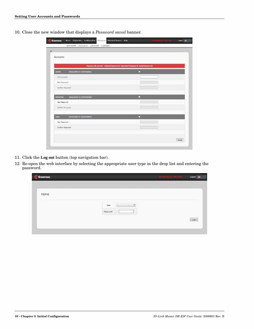
10. Close the new window that displays a Password saved banner.
11. Click the Log out button (top navigation bar).12. Re-open the web interface by selecting the appropriate user type in the drop list and entering the
password.
16 - Chapter 3. Initial Configuration IO-Link Master DR-EIP User Guide: 2000601 Rev. B
Configuring Miscellaneous Settings
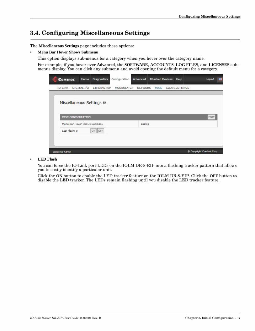
3.4. Configuring Miscellaneous Settings
The Miscellaneous Settings page includes these options:• Menu Bar Hover Shows Submenu
This option displays sub-menus for a category when you hover over the category name. For example, if you hover over Advanced, the SOFTWARE, ACCOUNTS, LOG FILES, and LICENSES sub-menus display. You can click any submenu and avoid opening the default menu for a category.
• LED Flash
You can force the IO-Link port LEDs on the IOLM DR-8-EIP into a flashing tracker pattern that allows you to easily identify a particular unit. Click the ON button to enable the LED tracker feature on the IOLM DR-8-EIP. Click the OFF button to disable the LED tracker. The LEDs remain flashing until you disable the LED tracker feature.
IO-Link Master DR-EIP User Guide: 2000601 Rev. B Chapter 3. Initial Configuration - 17

Configuring Miscellaneous Settings
18 - Chapter 3. Initial Configuration IO-Link Master DR-EIP User Guide: 2000601 Rev. B

Chapter 4. Connecting Devices
This chapter discusses connecting devices to the IOLM DR-8-EIP.After connecting your devices to the IOLM DR-8-EIP, you may need to use the next chapter to configure an appropriate IP address for your environment using Chapter 3. Initial Configuration on Page 11 before doing any port configuration.
4.1. Connecting to IO-Link Ports
The following provides information about the IO-Link ports.
Use the appropriate procedure to connect devices to the IO-Link ports.• Connecting IO-Link Devices on Page 20• Connecting Digital Input Devices to IO-Link Ports on Page 20
Signal Description Specifications
L+ Power Supply Output (+)200mA @ 24V (maximum)
L- Power Supply Output (-)
DI Digital Input
C/Q Communication signal, which supports SDCI (IO-Link) or SIO (standard input/output) 200mA @ 24V (maximum)
IO-Link Master DR-EIP User Guide: 2000601 Rev. B Chapter 4. Connecting Devices - 19
Tips When Connecting Devices to the IOLM DR-8-EIP
4.1.1. Tips When Connecting Devices to the IOLM DR-8-EIP
The following tips may be useful when connecting devices to the IOLM DR-8-EIP because it may be difficult to manipulate the wire-clamp screws on the adjacent ports.• If you are going to connect devices to Digital I/O ports (D1 through D4), connect the digital devices before
connecting devices to IO-Link ports.• Connect a device to IO-Link Port 1 before IO-Link Port 2 • Connect a device to IO-Link Port 4 before IO-Link Port 3 • Connect a device to IO-Link Port 5 before IO-Link Port 6• Connect a device to IO-Link Port 8 before IO-Link Port 7
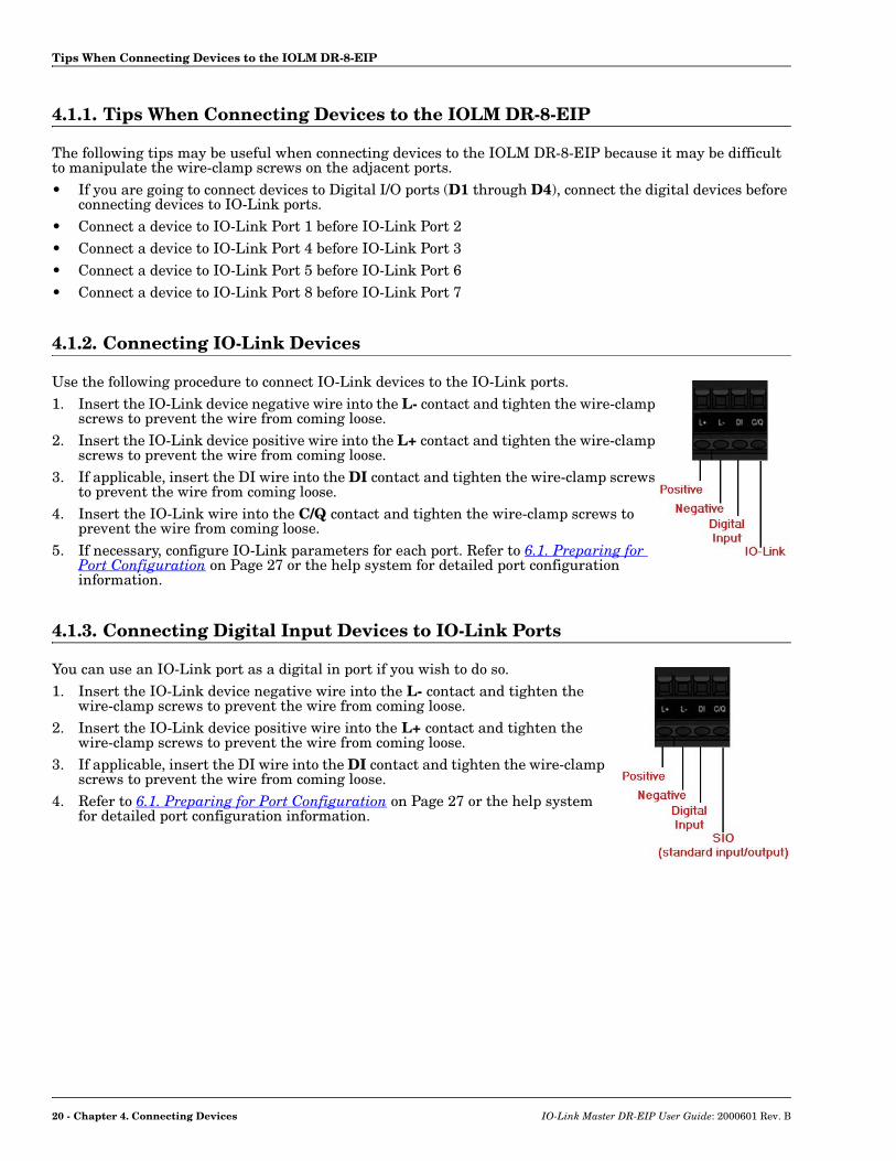
4.1.2. Connecting IO-Link Devices
Use the following procedure to connect IO-Link devices to the IO-Link ports.1. Insert the IO-Link device negative wire into the L- contact and tighten the wire-clamp
screws to prevent the wire from coming loose.2. Insert the IO-Link device positive wire into the L+ contact and tighten the wire-clamp
screws to prevent the wire from coming loose.3. If applicable, insert the DI wire into the DI contact and tighten the wire-clamp screws
to prevent the wire from coming loose.4. Insert the IO-Link wire into the C/Q contact and tighten the wire-clamp screws to
prevent the wire from coming loose.5. If necessary, configure IO-Link parameters for each port. Refer to 6.1. Preparing for
Port Configuration on Page 27 or the help system for detailed port configuration information.
4.1.3. Connecting Digital Input Devices to IO-Link Ports
You can use an IO-Link port as a digital in port if you wish to do so.1. Insert the IO-Link device negative wire into the L- contact and tighten the
wire-clamp screws to prevent the wire from coming loose.2. Insert the IO-Link device positive wire into the L+ contact and tighten the
wire-clamp screws to prevent the wire from coming loose.3. If applicable, insert the DI wire into the DI contact and tighten the wire-clamp
screws to prevent the wire from coming loose.4. Refer to 6.1. Preparing for Port Configuration on Page 27 or the help system
for detailed port configuration information.
20 - Chapter 4. Connecting Devices IO-Link Master DR-EIP User Guide: 2000601 Rev. B

Connecting Digital IO Ports
4.2. Connecting Digital IO Ports
The IOLM DR-8-EIP provides four digital IO ports.
You can connect a digital input device to DI and/or DIO. DIO supports digital out.
4.2.1. Connecting to DI
Use this procedure to connect a digital input device using the DI terminal on a DIO port.1. Insert the IO-Link device negative wire into the L- contact and tighten the wire-clamp
screws to prevent the wire from coming loose.2. Insert the IO-Link device positive wire into the L+ contact and tighten the wire-clamp
screws to prevent the wire from coming loose.3. Insert the DI wire into the DI contact and tighten the wire-clamp screws to prevent the
wire from coming loose.4. Go to the Configuration | Digital I/O Settings page to configure the port. If necessary, refer to
the help system or 6.2. IO-Link Configuration Page on Page 29.
Signal Description Specifications
L+ Power Supply (+)200mA @ 24V (maximum)
L- Power Supply (-)
DI Digital Input
DIO Digital I/O 200mA @ 24V (maximum)
IO-Link Master DR-EIP User Guide: 2000601 Rev. B Chapter 4. Connecting Devices - 21

Connecting to DIO
4.2.2. Connecting to DIO
1. Insert the IO-Link device negative wire into the L- contact and tighten the wire-clamp screws to prevent the wire from coming loose.
2. Insert the IO-Link device positive wire into the L+ contact and tighten the wire-clamp screws to prevent the wire from coming loose.
3. Insert the DI wire into the DIO contact and tighten the wire-clamp screws to prevent the wire from coming loose.
4. Go to the Configuration | Digital I/O Settings page to configure the port. If necessary, refer to the help system or 6.2. IO-Link Configuration Page on Page 29.
22 - Chapter 4. Connecting Devices IO-Link Master DR-EIP User Guide: 2000601 Rev. B

Chapter 5. Updating Images and Applications
This chapter provides an overview of the software (images and applications) on the IOLM DR-8-EIP. In addition it contains procedures to update images (Page 25) and application subassemblies (Page 26).After verifying that the IOLM DR-8-EIP contains the latest software, the next step is to configure the port characteristics using Chapter 6. IO-Link Port Configuration on Page 27 and/or Chapter 7. Dedicated Digital I/O Port Configuration on Page 47.
5.1. Images and Application Subassemblies Overview
The IOLM DR-8-EIP is loaded with the latest images at the factory but you may need to update images or application subassemblies to have access to the latest features.You can view all image and application versions in the IOLM DR-8-EIP ADVANCED | Software page.
Optionally, you can use PortVision DX to load all images or application subassemblies. Note: PortVision DX displays the main application base version, which in this case is EtherNet/IP. Use the
Software page to determine other image or application versions.
IO-Link Master DR-EIP User Guide: 2000601 Rev. B Chapter 5. Updating Images and Applications - 23

Images
5.1.1. Images
The following table discusses IOLM DR-8-EIP images.
5.1.2. Application Subassemblies
Application subassemblies are the components of the Application Base image. Application subassemblies have 3-tuple or 4-tuple version numbers (for example, 1.10.1). The first two values in a subassembly version correspond to the version of the application base assembly for which it was built and tested. For example, a subassembly with version 1.10.3 was tested with application base version 1.10. When using the Software page or PortVision DX, an application subassembly can install only if its version number matches that of the installed application base assembly. A subassembly with a version of 1.20.2.4 only installs if the application base version is 1.20. It will not install on a device with application base version 1.09 or 1.20.
IOLM DR-8-EIP Images
U-Boot Bootloader
U-Boot is a high-level Bootloader that has networking and console command line capabilities. Among other things, it implements a TFTP server and Comtrol Corporation's new discovery protocol.This verifies that a Linux kernel image exists in NAND, then copies it to RAM and starts the IOLM DR-8-EIP. The U-Boot version is displayed after the image name.
FPGA
The FPGA partition/image contains configuration data used by programmable hardware within the IOLM DR-8-EIP unit.FPGA images are unique to the hardware and protocol type. Make sure you download the correct image for your platform.
uImage - Primary/Backup
The uImage contains the Linux kernel and the RAM-resident root file system. It does not contain industrial protocol support or application-specific features. There is a Primary and Backup version loaded on the IOLM DR-8-EIP. The IOLM DR-8-EIP automatically reloads the Backup uImage if the file system corrupted. The uImage version is displayed after the Primary/Backup uImage.
Application Base
The Application Base image comprises a flash-resident file system containing applications and protocol support. The Application Base is built from a collection of application subassemblies -- each of which may be updated individually between releases of the application base as a whole. The application subassemblies in the Application Base image are displayed in the lower portion of the SOFTWARE page. The Application Base assembly has a 2-tuple version number: (for example, 1.10).
IOLM DR-8-EIP Application Subassemblies
application-manager The Application Manager version loaded on the IOLM DR-8-EIP.
configuration-manager The Configuration Manager version loaded on the IOLM DR-8-EIP.
discovery-protocol The Discovery Protocol version loaded on the IOLM DR-8-EIP.
ethernetip The EtherNet/IP and Modbus/TCP interfaces version loaded on the IOLM DR-8-EIP.
event-log The Event log version loaded on the IOLM DR-8-EIP.
iolink-driver The IO-Link driver version loaded on the IOLM DR-8-EIP.
web-help The web interface help version loaded on the IOLM DR-8-EIP.
web-user-interface The web interface version loaded on the IOLM DR-8-EIP.
24 - Chapter 5. Updating Images and Applications IO-Link Master DR-EIP User Guide: 2000601 Rev. B

Using the Web Interface to Update Software
5.2. Using the Web Interface to Update Software
The upper portion of this page is used to update the IOLM DR-8-EIP images. The lower portion of this page is used for updating application subassemblies that are integrated in the Application Base. Typically, the latest application subassemblies are available in the Application Base image. There may times when a feature enhancement or bug fix is available in an application subassembly and not yet available in the Application Base image.
5.2.1. Updating Images
Use this procedure to upload images using the SOFTWARE page.1. Download the latest image from the Comtrol ftp site.2. Open your browser and enter the IP address of the IOLM DR-8-EIP.3. Click Advanced | SOFTWARE.4. Click the UPDATE button next to the image you want to update.5. Click the Browse button and click Open.6. Click the Install button.
7. Click the CONTINUE button to the Update Image message.
IO-Link Master DR-EIP User Guide: 2000601 Rev. B Chapter 5. Updating Images and Applications - 25
Updating Application Subassemblies
8. Click OK to close the Update Image Successful message.Note: Some images may require the IOLM DR-8-EIP web server to restart.
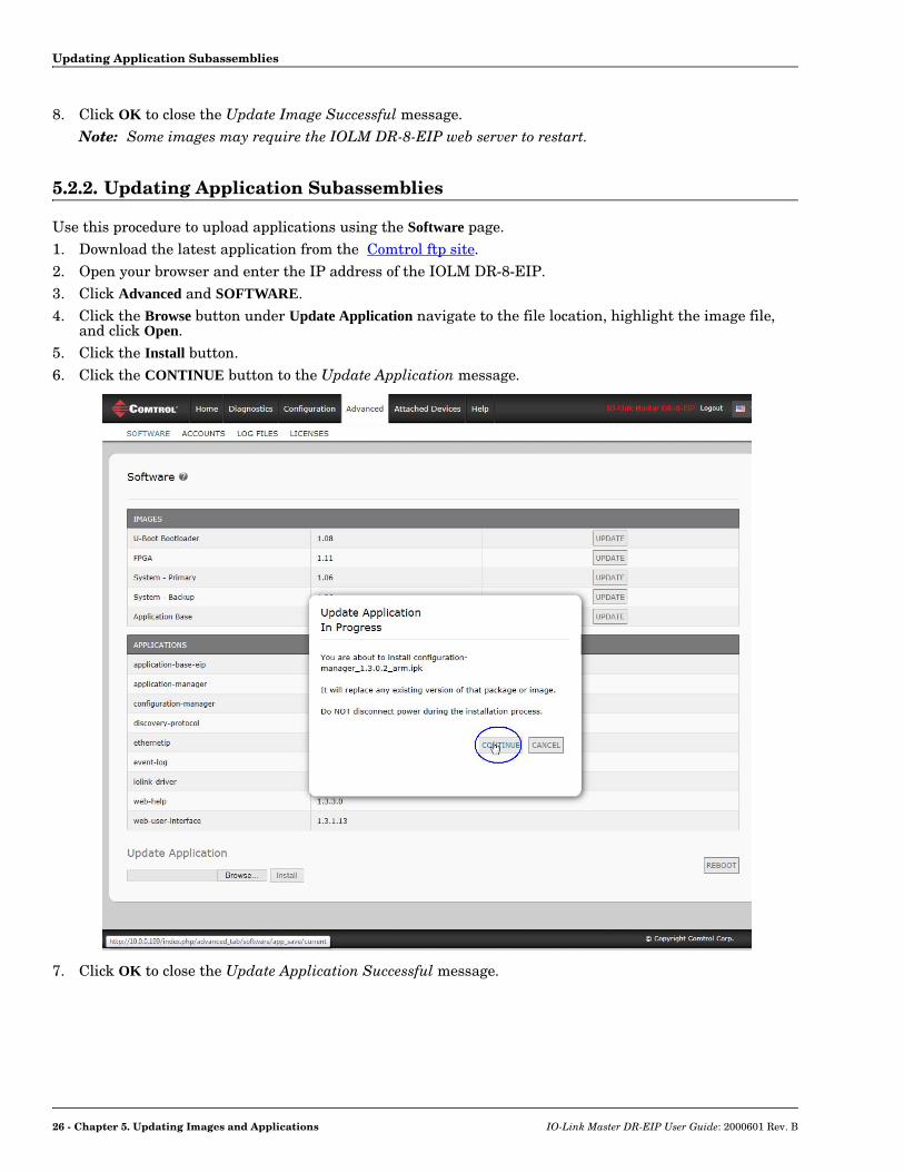
5.2.2. Updating Application Subassemblies
Use this procedure to upload applications using the Software page.1. Download the latest application from the Comtrol ftp site.2. Open your browser and enter the IP address of the IOLM DR-8-EIP.3. Click Advanced and SOFTWARE.4. Click the Browse button under Update Application navigate to the file location, highlight the image file,
and click Open.5. Click the Install button.6. Click the CONTINUE button to the Update Application message.
7. Click OK to close the Update Application Successful message.
26 - Chapter 5. Updating Images and Applications IO-Link Master DR-EIP User Guide: 2000601 Rev. B
Chapter 6. IO-Link Port Configuration
This chapter discusses port configuration, which includes these topics:• Preparing for Port Configuration• IO-Link Configuration Page on Page 29• EtherNet/IP Settings Configuration Page on Page 34• Modbus/TCP Settings Configuration Page on Page 41Note: See Chapter 7. Dedicated Digital I/O Port Configuration on Page 47 for information about configuring
dedicated digital I/O ports.Depending on your environment, the IO-Link Master you may not need to change many of the default options.
6.1. Preparing for Port Configuration
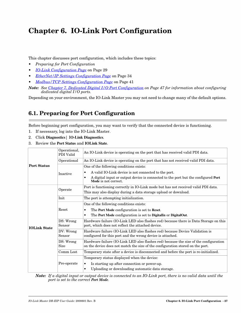
Before beginning port configuration, you may want to verify that the connected device is functioning.1. If necessary, log into the IO-Link Master.2. Click Diagnostics| IO-Link Diagnostics.3. Review the Port Status and IOLink State.
Note: If a digital input or output device is connected to an IO-Link port, there is no valid data until the port is set to the correct Port Mode.
Port Status
Operational, PDI Valid
An IO-Link device is operating on the port that has received valid PDI data.
Operational An IO-Link device is operating on the port that has not received valid PDI data.
Inactive
One of the following conditions exists:
• A valid IO-Link device is not connected to the port.• A digital input or output device is connected to the port but the configured Port
Mode is not correct.
IOLink State
OperatePort is functioning correctly in IO-Link mode but has not received valid PDI data.This may also display during a data storage upload or download.
Init The port is attempting initialization.
Reset
One of the following conditions exists:
• The Port Mode configuration is set to Reset.• The Port Mode configuration is set to DigitalIn or DigitalOut.
DS: Wrong Sensor
Hardware failure (IO-Link LED also flashes red) because there is Data Storage on this port, which does not reflect the attached device.
DV: Wrong Sensor
Hardware failure (IO-Link LED also flashes red) because Device Validation is configured for this port and the wrong device is attached.
DS: Wrong Size
Hardware failure (IO-Link LED also flashes red) because the size of the configuration on the device does not match the size of the configuration stored on the port.
Comm Lost Temporary state after a device is disconnected and before the port is re-initialized.
Pre-operate
Temporary status displayed when the device:
• Is starting up after connection or power-up.• Uploading or downloading automatic data storage.
IO-Link Master DR-EIP User Guide: 2000601 Rev. B Chapter 6. IO-Link Port Configuration - 27
Preparing for Port Configuration
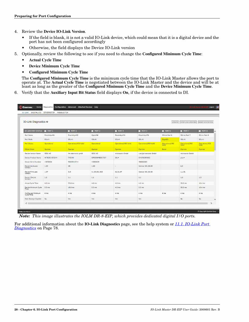
4. Review the Device IO-Link Version. • If the field is blank, it is not a valid IO-Link device, which could mean that it is a digital device and the
port has not been configured accordingly• Otherwise, the field displays the Device IO-Link version
5. Optionally, review the following to see if you need to change the Configured Minimum Cycle Time:• Actual Cycle Time
• Device Minimum Cycle Time
• Configured Minimum Cycle Time
The Configured Minimum Cycle Time is the minimum cycle time that the IO-Link Master allows the port to operate at. The Actual Cycle Time is negotiated between the IO-Link Master and the device and will be at least as long as the greater of the Configured Minimum Cycle Time and the Device Minimum Cycle Time.
6. Verify that the Auxiliary Input Bit Status field displays On, if the device is connected to DI.
For additional information about the IO-Link Diagnostics page, see the help system or 11.1. IO-Link Port Diagnostics on Page 78.
Note: This image illustrates the IOLM DR-8-EIP, which provides dedicated digital I/O ports.
28 - Chapter 6. IO-Link Port Configuration IO-Link Master DR-EIP User Guide: 2000601 Rev. B

IO-Link Configuration Page
6.2. IO-Link Configuration Page
Use the Configuration | IO-Link Settings page to configure IO-Link port characteristics for the IO-Link Master.This subsection discusses:• Editing IO-Link Settings on Page 30• IO-Link Settings Parameters on Page 31.
Note: This image shows the IOLM DR-8-EIP, which provides dedicated Digital I/O ports and a Configuration page.
IO-Link Master DR-EIP User Guide: 2000601 Rev. B Chapter 6. IO-Link Port Configuration - 29
Editing IO-Link Settings
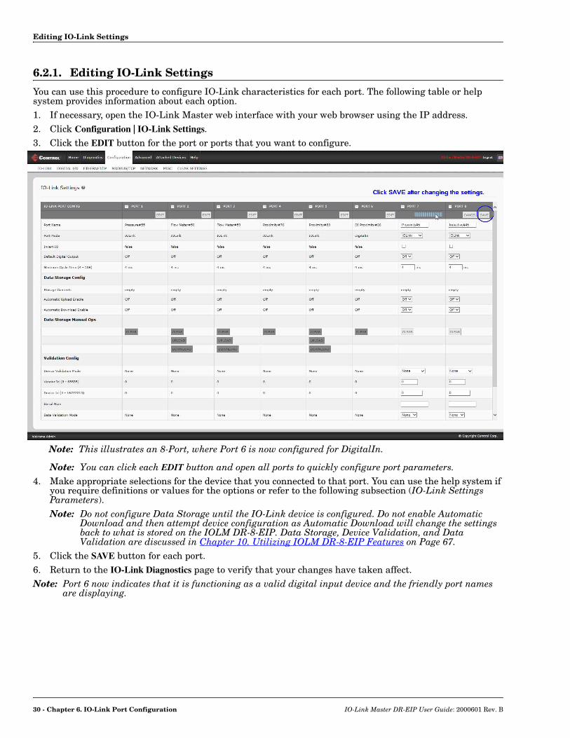
6.2.1. Editing IO-Link Settings
You can use this procedure to configure IO-Link characteristics for each port. The following table or help system provides information about each option.1. If necessary, open the IO-Link Master web interface with your web browser using the IP address.2. Click Configuration | IO-Link Settings.3. Click the EDIT button for the port or ports that you want to configure.
Note: You can click each EDIT button and open all ports to quickly configure port parameters.4. Make appropriate selections for the device that you connected to that port. You can use the help system if
you require definitions or values for the options or refer to the following subsection (IO-Link Settings Parameters).Note: Do not configure Data Storage until the IO-Link device is configured. Do not enable Automatic
Download and then attempt device configuration as Automatic Download will change the settings back to what is stored on the IOLM DR-8-EIP. Data Storage, Device Validation, and Data Validation are discussed in Chapter 10. Utilizing IOLM DR-8-EIP Features on Page 67.
5. Click the SAVE button for each port.6. Return to the IO-Link Diagnostics page to verify that your changes have taken affect.Note: Port 6 now indicates that it is functioning as a valid digital input device and the friendly port names
are displaying.
Note: This illustrates an 8-Port, where Port 6 is now configured for DigitalIn.
30 - Chapter 6. IO-Link Port Configuration IO-Link Master DR-EIP User Guide: 2000601 Rev. B

IO-Link Settings Parameters
6.2.2. IO-Link Settings Parameters
The Configuration | IO-Link Settings page supports the following options.
IO-LINK Settings Page
Port NameUser defined port or device description.• Standard ASCII characters• Max length = 80 characters
Port ModeDefault: IO-Link
Selected IO-Link Port Mode. Valid settings are:• Reset
• IO-Link
• Digital In
• Digital Out
Invert IODefault: False
If enabled and the Port Mode is Digital In or Digital Out, inverts the I/O value.• False (Disabled - Do not invert IO)• True (Enabled - Invert IO)Note: Does not affect the Auxiliary Input.
Default Digital OutputDefault: Off
If the port mode is Digital Out, defines the default digital output value that is used at startup and when there is no active PDO controller.• Off (low voltage) - 0• On (high voltage - 24V)
Minimum Cycle TimeDefault: 4
The minimum, or fastest, cycle time that the IO-Link device may operate at. The valid range is 4-538 ms.You can leave the Minimum Cycle Time set to the default value and the IO-Link Master negotiates with the IO-Link device for its minimum cycle time. The IO-Link Diagnostics page displays the Actual Cycle Time, which is the negotiated cycle time.
Data Storage Config
Storage Contents Indicates that the data storage for the port is empty or displays the Vendor ID and Product ID of the data stored on that port.
Automatic Data Storage Upload EnableDefault: Off
When this option is initially set to On, the storage data on the IO-Link device is uploaded, and saved on the IO-Link Master for that port.You may want to enable Automatic Upload after you have initially configured the IO-Link device attached to the port.Refer to 10.1. Data Storage on Page 67 for more information.
Automatic Data Storage Download EnableDefault: Off
The data stored on the IO-Link Master port is downloaded to the IO-Link device if:1. This option is selected.2. The data stored on the IO-Link Master port contains the same Vendor ID and
Product ID as the IO-Link device connected to the port.3. The data stored on the IO-Link Master port is different than that of the IO-
Link device.
IO-Link Master DR-EIP User Guide: 2000601 Rev. B Chapter 6. IO-Link Port Configuration - 31

IO-Link Settings Parameters
Data Storage Manual Ops
Manual Data Storage Ops provide the following functionality, if data storage is supported by the IO-Link device.CLEAR - this clears any stored data for an IO-Link device on this port.UPLOAD - this uploads and stores the IO-Link device configuration on the IO-Link Master.DOWNLOAD - this downloads the stored IO-Link device configuration from the IO-Link Master to the IO-Link device attached to this port if the Vendor ID and Device ID match.
Validation Config
Device Validation Mode(Default: None)
Device Validation Mode provides these options:• None - this disables Device Validation Mode.• Compatible - permits a compatible IO-Link device (same Vendor ID and Device
ID) to function on the corresponding port.• Identical - only permits an IO-Link device to function on the corresponding port
as defined in the following fields.- Vendor ID- Device ID- Serial Number
Vendor Id (0-65535)This is required if you select a Device Validation Mode other than None.The Vendor ID can be manually entered in this field or click the GET ATTACHED button and the IO-Link Master propagates the Vendor ID in this field.
Device Id (0-16777215)This is required if you select a Device Validation Mode other than None.The Device ID can be manually entered in this field or click the GET ATTACHED button and the IO-Link Master propagates the Device ID in this field.
Serial Num
This is required if you select Identical for the Device Validation Mode.The Serial Number can be manually entered in this field or click the GET ATTACHED button and the IO-Link Master propagates the serial number in this field.
Data Validation Mode(Default: None)
There are three Data Validation Modes:• None - no data validation is performed on the port.• Loose - the slave device's PDI/PDO lengths must be less than or equal to the
user-configured values.• Strict - the slave device's PDI/PDO lengths must be the same as the user-
configured values.
PDI Length (0-32)
This is input length of the PDI data field.This is required if you select a Data Validation Mode other than None.The PDI Length can be manually entered in this field or click the GET ATTACHED button and the IO-Link Master propagates the PDI length in this field.
PDO Length (0-32)
This is input length of the PDO data field.This is required if you select a Data Validation Mode other than None.The PDO Length can be manually entered in this field or click the GET ATTACHED button and the IO-Link Master propagates the PDO length in this field
IO-LINK Settings Page (Continued)
32 - Chapter 6. IO-Link Port Configuration IO-Link Master DR-EIP User Guide: 2000601 Rev. B
IO-Link Settings Parameters
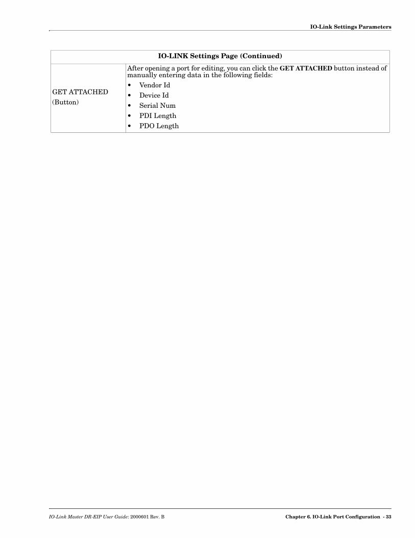
GET ATTACHED(Button)
After opening a port for editing, you can click the GET ATTACHED button instead of manually entering data in the following fields:• Vendor Id• Device Id• Serial Num• PDI Length• PDO Length
IO-LINK Settings Page (Continued)
IO-Link Master DR-EIP User Guide: 2000601 Rev. B Chapter 6. IO-Link Port Configuration - 33

EtherNet/IP Settings Configuration Page
6.3. EtherNet/IP Settings Configuration Page
Use the EtherNet/IP Settings page to configure EtherNet/IP options.You may want to refer to the IO-Link Master EtherNet/IP Reference Manual for additional information. The IO-Link Master Reference Manuals also contain information about:• RSLogix 5000 program examples. • Connecting SLC, PLC-5, or MicroLogix PLCs.• Adding EDS files to RSLinx for normal IO-Link Master-to-PLC communicationsThis subsection includes the following topics:• Editing EtherNet/IP Settings on Page 35• EtherNet/IP Settings Parameters on Page 36Note: The IO-Link Master may work out of the box for ControlLogix PLCs.
Note: This illustrate a partial screen shot, scroll through the settings table to view all of the available settings.
34 - Chapter 6. IO-Link Port Configuration IO-Link Master DR-EIP User Guide: 2000601 Rev. B

Editing EtherNet/IP Settings
6.3.1. Editing EtherNet/IP Settings
You can use this procedure to configure EtherNet/IP characteristics for each port.1. If necessary, open the IO-Link Master web interface with your web browser using the IP address.2. Click Configuration | EtherNet/IP.3. Click the EDIT button for each port that you want to configure.
Note: You can click each EDIT button and open all ports to quickly configure port parameters.4. Make appropriate selections for the device that is connected to the port.
You can use the help system if you require definitions or values for the options or refer to EtherNet/IP Settings Parameters in the next subsection.
5. Scroll to the top of the page and click the SAVE button.Make sure that the port now displays the EDIT button.
IO-Link Master DR-EIP User Guide: 2000601 Rev. B Chapter 6. IO-Link Port Configuration - 35

EtherNet/IP Settings Parameters
6.3.2. EtherNet/IP Settings Parameters
The Configuration | EtherNet/IP Settings page supports the following options.
EtherNet/IP Settings Page
ISDU Data Settings
ISDU Response TimeoutDefault: 20 seconds
The time that the IO-Link Master’s EtherNet/IP interface waits for a response to an ISDU request. The timeout needs to set long enough to allow all commands within the ISDU request to be processed. Valid range: 1-10,000 seconds
Process Data Settings
PDI Data Block Size (To PLC)Default: 36-bytes
The configurable PDI data block length. Supported optional lengths are:• 4-bytes (header only)• 8-bytes (4 bytes data)• 16-bytes (12 bytes data)• 24-bytes (20 bytes data)• 36-bytes (32 bytes data)
PDI Data Block Format (To PLC)Default: Word-16
Data format of PDI data block to be transferred to the PLC(s) in Class 1 and/or Write-to-Tag/File PDI Transfer Modes. Supported formats are:• Byte-8 (8-bit or SINT)• Word-16 (16-bit or INT)• Dword-32 (32-bit or DINT)Note: The Data Block Format is independent of the PDI Data Byte-Swap
Method. This setting is not used for the SLC, PLC-5 and MicroLogix PLCs which are always Word-16.
PDI Data Byte-Swap MethodDefault: Work (16-bit) byte swap
If enabled, the IO-Link Master swaps the data bytes in word (2 byte) format or dword (4 byte) format.Supported values are:• No byte-swap – data passed through as received• Word (16-bit) byte-swap – data is byte-swapped in word format• Dword (32-bit) byte-swap – data is byte-swapped in dword formatNote: The byte swapping must be set correctly in order to convert from IO-
Link (big-endian byte order), to EtherNet/IP (little-endian byte order).
Include Digital I/O in PDI Data Block Default: False
If enabled, the IO-Link Master includes the current digital I/O pins D1 to D4 status in the PDI data block header.• False – Do not include the digital I/O pins status• True (enable check box) – Include the digital I/O pins status in PDI data
block headerNote: Does not affect the Auxiliary Input.
36 - Chapter 6. IO-Link Port Configuration IO-Link Master DR-EIP User Guide: 2000601 Rev. B
EtherNet/IP Settings Parameters
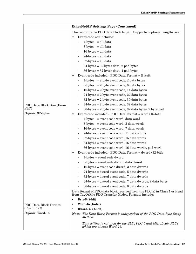
PDO Data Block Size (From PLC)Default: 32-bytes
The configurable PDO data block length. Supported optional lengths are:• Event code not included:
- 4-bytes = all data- 8-bytes = all data- 16-bytes = all data- 24-bytes = all data- 32-bytes = all data- 34-bytes = 32 bytes data, 2 pad bytes- 36-bytes = 32 bytes data, 4 pad bytes
• Event code included - PDO Data Format = Byte8:- 4-bytes = 2 byte event code, 2 data bytes- 8-bytes = 2 byte event code, 6 data bytes- 16-bytes = 2 byte event code, 14 data bytes- 24-bytes = 2 byte event code, 22 data bytes- 32-bytes = 2 byte event code, 30 data bytes- 34-bytes = 2 byte event code, 32 data bytes- 36-bytes = 2 byte event code, 32 data bytes, 2 byte pad
• Event code included - PDO Data Format = word (16-bit):- 4-bytes = event code word, data word- 8-bytes = event code word, 3 data words- 16-bytes = event code word, 7 data words- 24-bytes = event code word, 11 data words- 32-bytes = event code word, 15 data words- 34-bytes = event code word, 16 data words- 36-bytes = event code word, 16 data words, pad word
• Event code included - PDO Data Format = dword (32-bit):- 4-bytes = event code dword- 8-bytes = event code dword, data dword- 16-bytes = event code dword, 3 data dwords- 24-bytes = dword event code, 5 data dwords- 32-bytes = dword event code, 7 data dwords- 34-bytes = dword event code, 7 data dwords, 2 data bytes- 36-bytes = dword event code, 8 data dwords
PDO Data Block Format (From PLC)Default: Word-16
Data format of PDO data block received from the PLC(s) in Class 1 or Read from TagOrFile PDO Transfer Modes. Formats include:• Byte-8 (8-bit)
• Word-16 (16-bit)
• Dword-32 (32-bit)
Note: The Data Block Format is independent of the PDO Data Byte-Swap Method. This setting is not used for the SLC, PLC-5 and MicroLogix PLCs which are always Word-16.
EtherNet/IP Settings Page (Continued)
IO-Link Master DR-EIP User Guide: 2000601 Rev. B Chapter 6. IO-Link Port Configuration - 37

EtherNet/IP Settings Parameters
PDO Data Byte-Swap MethodDefault: Word (16-bit) byte-swap
If enabled, the IO-Link Master swaps the data bytes in word (2 byte) format or dword (4 byte) format. Supported values are:• No byte-swap – data passed through as received• Word (16-bit) byte-swap – data is byte-swapped in word format• Dword (32-bit) byte-swap – data is byte-swapped in dword formatNote: The byte swapping must be set correctly in order to convert from
EtherNet/IP (little-endian byte order), to IO-Link (big-endian byte order).
Clear Event Code in PDO BlockDefault: False
If enabled, the IO-Link Master expects the first 2 bytes, word, or dword of the PDO block to be used for event code handling. Supported values are:• True (enable check box) = expect event code• False = no event code, expect only PDO data
Clear Event Code After Hold TimeDefault: True
If enabled, the IO-Link Master clears any event code reported in the PDI data block after the Event Active Hold Time. Supported values are:• True (enable check box) = clear event code after hold time• False = do not clear event code after hold time
Event Active Hold TimeDefault: 1000 ms
If Clear Event Code After Hold time is enabled, the time period an event code is reported in the PDI block before it is cleared.• Valid range: 1-65535
• Valid Units:- ms (milliseconds)- sec (seconds)- min (minutes)- hours
- days
Clear Event Hold TimeDefault: 500 ms
Once an event code has been cleared, the time an event code stays cleared in the PDI block before another event code can be reported.• Valid range: 1-65535
• Valid Units:- ms (milliseconds)- sec (seconds)- min (minutes)- hours
- days
Include Digital Output(s) in PDO Data Block Default: False
If enabled, the IO-Link Master expects the digital output settings to be included in the PDO data block.False – The digital pin setting(s) are not included in the PDO data block.True (enable check box) – The digital pin setting(s) are included in the PDO data block.
EtherNet/IP Settings Page (Continued)
38 - Chapter 6. IO-Link Port Configuration IO-Link Master DR-EIP User Guide: 2000601 Rev. B
EtherNet/IP Settings Parameters
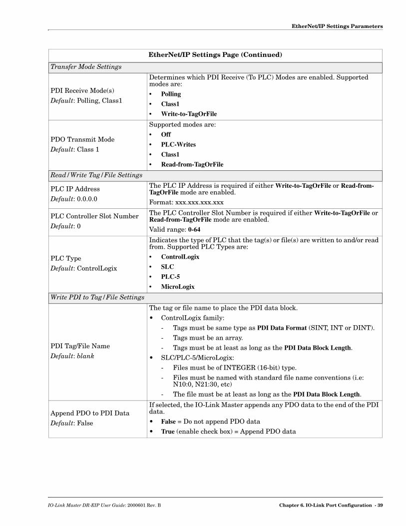
Transfer Mode Settings
PDI Receive Mode(s)Default: Polling, Class1
Determines which PDI Receive (To PLC) Modes are enabled. Supported modes are:• Polling
• Class1
• Write-to-TagOrFile
PDO Transmit ModeDefault: Class 1
Supported modes are:• Off
• PLC-Writes
• Class1
• Read-from-TagOrFile
Read/Write Tag/File Settings
PLC IP AddressDefault: 0.0.0.0
The PLC IP Address is required if either Write-to-TagOrFile or Read-from-TagOrFile mode are enabled.Format: xxx.xxx.xxx.xxx
PLC Controller Slot NumberDefault: 0
The PLC Controller Slot Number is required if either Write-to-TagOrFile or Read-from-TagOrFile mode are enabled.Valid range: 0-64
PLC TypeDefault: ControlLogix
Indicates the type of PLC that the tag(s) or file(s) are written to and/or read from. Supported PLC Types are:• ControlLogix
• SLC
• PLC-5
• MicroLogix
Write PDI to Tag/File Settings
PDI Tag/File NameDefault: blank
The tag or file name to place the PDI data block.• ControlLogix family:
- Tags must be same type as PDI Data Format (SINT, INT or DINT).- Tags must be an array. - Tags must be at least as long as the PDI Data Block Length.
• SLC/PLC-5/MicroLogix:- Files must be of INTEGER (16-bit) type.- Files must be named with standard file name conventions (i.e:
N10:0, N21:30, etc)- The file must be at least as long as the PDI Data Block Length.
Append PDO to PDI DataDefault: False
If selected, the IO-Link Master appends any PDO data to the end of the PDI data. • False = Do not append PDO data• True (enable check box) = Append PDO data
EtherNet/IP Settings Page (Continued)
IO-Link Master DR-EIP User Guide: 2000601 Rev. B Chapter 6. IO-Link Port Configuration - 39

EtherNet/IP Settings Parameters
Maximum PLC Update RateDefault: 40ms
The maximum rate at which the IO-Link Master updates the PDI tag or file. This parameter is used to ensure that the PLC receives all state changes. Setting the update rate to 10 ms effectively disables this feature. The valid range is 10 to 65535 ms.
Heartbeat Update EnableDefault: False
If selected, the IO-Link Master updates the PDI data block at the Heartbeat Update Rate.• False = Heartbeat update disabled• True (enable check box) = Heartbeat update enabled
Heartbeat Update RateDefault: 1000ms
If Heartbeat Update Enable is selected, the rate at which the IO-Link Master updates the PDI data block in the Write-to-Tag/File mode. The valid range is 50 to 65535 ms.
Read PDO from Tag/File Settings
PDO Tag/File NameDefault: blank
The tag or file name that the IO-Link Master reads the PDO data block from.• ControlLogix family:
- Tags must be same type as PDO Data Format (SINT, INT or DINT).- Tags must be an array. - Tags must be at least as long as the PDO Data Block Length.
• SLC/PLC-5/MicroLogix:- Files must be of INTEGER (16-bit) type.- Files must be named with standard file name conventions (i.e:
N10:0, N21:30, etc)The file must be at least as long as the PDO Data Block Length.
PLC Poll RateDefault: 1000ms
The frequency which the IO-Link Master reads the PDO data block in the Read-from-Tag/File mode.Valid range: 50-65535 ms
EtherNet/IP Settings Page (Continued)
40 - Chapter 6. IO-Link Port Configuration IO-Link Master DR-EIP User Guide: 2000601 Rev. B
Modbus/TCP Settings Configuration Page
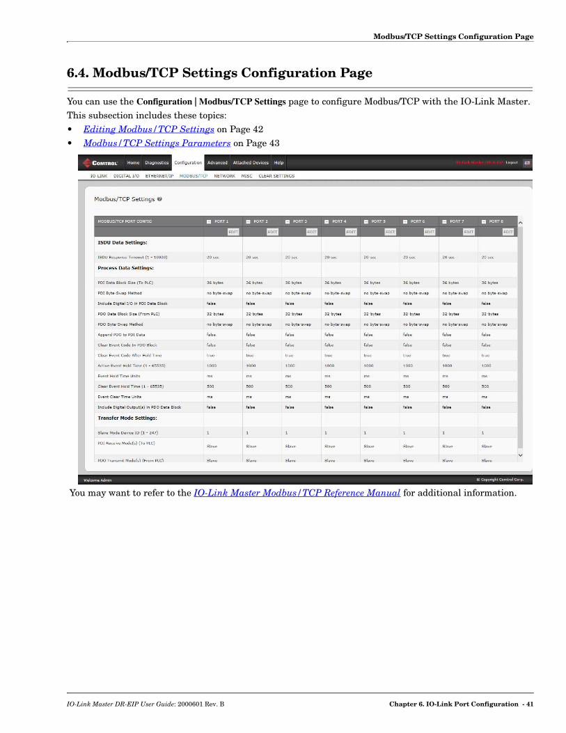
6.4. Modbus/TCP Settings Configuration Page
You can use the Configuration | Modbus/TCP Settings page to configure Modbus/TCP with the IO-Link Master.This subsection includes these topics:• Editing Modbus/TCP Settings on Page 42• Modbus/TCP Settings Parameters on Page 43
You may want to refer to the IO-Link Master Modbus/TCP Reference Manual for additional information.
IO-Link Master DR-EIP User Guide: 2000601 Rev. B Chapter 6. IO-Link Port Configuration - 41
Editing Modbus/TCP Settings
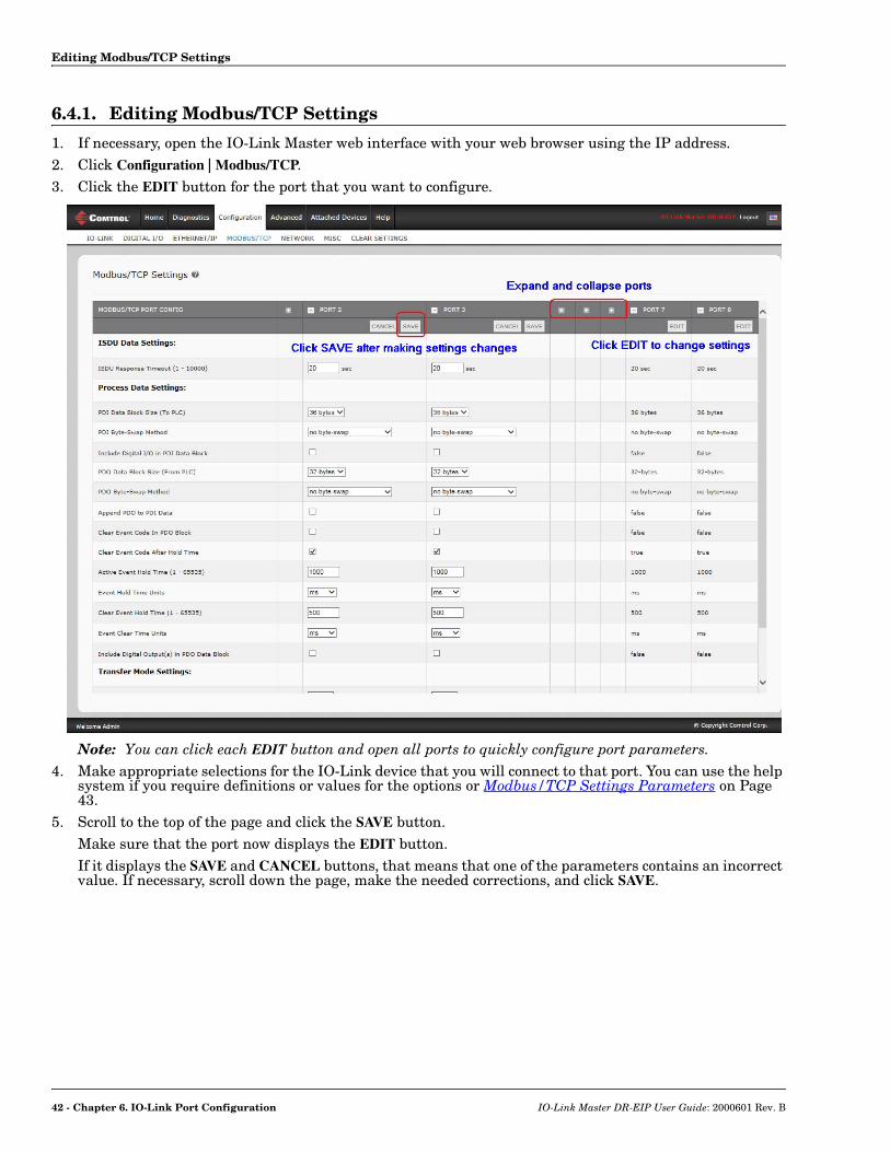
6.4.1. Editing Modbus/TCP Settings
1. If necessary, open the IO-Link Master web interface with your web browser using the IP address.2. Click Configuration | Modbus/TCP.3. Click the EDIT button for the port that you want to configure.
Note: You can click each EDIT button and open all ports to quickly configure port parameters.4. Make appropriate selections for the IO-Link device that you will connect to that port. You can use the help
system if you require definitions or values for the options or Modbus/TCP Settings Parameters on Page 43.
5. Scroll to the top of the page and click the SAVE button.Make sure that the port now displays the EDIT button. If it displays the SAVE and CANCEL buttons, that means that one of the parameters contains an incorrect value. If necessary, scroll down the page, make the needed corrections, and click SAVE.
42 - Chapter 6. IO-Link Port Configuration IO-Link Master DR-EIP User Guide: 2000601 Rev. B
Modbus/TCP Settings Parameters
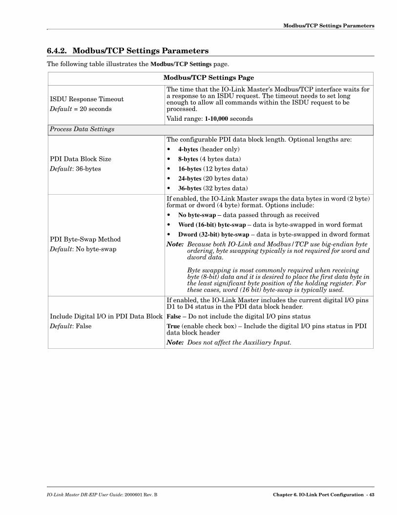
6.4.2. Modbus/TCP Settings Parameters
The following table illustrates the Modbus/TCP Settings page.
Modbus/TCP Settings Page
ISDU Response TimeoutDefault = 20 seconds
The time that the IO-Link Master’s Modbus/TCP interface waits for a response to an ISDU request. The timeout needs to set long enough to allow all commands within the ISDU request to be processed. Valid range: 1-10,000 seconds
Process Data Settings
PDI Data Block SizeDefault: 36-bytes
The configurable PDI data block length. Optional lengths are:• 4-bytes (header only)• 8-bytes (4 bytes data)• 16-bytes (12 bytes data)• 24-bytes (20 bytes data)• 36-bytes (32 bytes data)
PDI Byte-Swap MethodDefault: No byte-swap
If enabled, the IO-Link Master swaps the data bytes in word (2 byte) format or dword (4 byte) format. Options include:• No byte-swap – data passed through as received• Word (16-bit) byte-swap – data is byte-swapped in word format• Dword (32-bit) byte-swap – data is byte-swapped in dword formatNote: Because both IO-Link and Modbus/TCP use big-endian byte
ordering, byte swapping typically is not required for word and dword data. Byte swapping is most commonly required when receiving byte (8-bit) data and it is desired to place the first data byte in the least significant byte position of the holding register. For these cases, word (16 bit) byte-swap is typically used.
Include Digital I/O in PDI Data BlockDefault: False
If enabled, the IO-Link Master includes the current digital I/O pins D1 to D4 status in the PDI data block header.False – Do not include the digital I/O pins statusTrue (enable check box) – Include the digital I/O pins status in PDI data block headerNote: Does not affect the Auxiliary Input.
IO-Link Master DR-EIP User Guide: 2000601 Rev. B Chapter 6. IO-Link Port Configuration - 43

Modbus/TCP Settings Parameters
PDO Data Block SizeDefault: 32-bytes
The configurable PDO data block length. Optional lengths are:Event code not included:• 4-bytes = 2 data words• 8-bytes = 4 data words• 16-bytes = 8 data words• 24-bytes = 12 data words• 32-bytes = 16 data words• 34-bytes = 16 data words, 1 pad word Event code included:• 4-bytes = event code word, 1 data word• 8-bytes = event code word, 3 data words• 16-bytes = event code word, 7 data words• 24-bytes = event code word, 11 data words• 32-bytes = event code word, 15 data words• 34-bytes = event code word, 16 data words
PDO Byte-Swap MethodDefault: No byte-swap
If enabled, the IO-Link Master swaps the data bytes in word (2 byte) format or dword (4 byte) format. Options include:• No byte-swap – data passed through as received• Word (16-bit) byte-swap – data is byte-swapped in word format• Dword (32-bit) byte-swap – data is byte-swapped in dword formatNote: Because both IO-Link and Modbus/TCP use big-endian byte
ordering, byte swapping typically is not required for word and dword data. Byte swapping is most commonly required when sending byte (8-bit) data to the IO-Link device and it is desired to send the least significant byte of the holding register first. For these cases, word (16 bit) byte-swap is typically used.
Append PDO to PDI DataDefault: False
If selected, the IO-Link Master appends any PDO data to the end of the PDI data. • False = Do not append PDO data• True (enable check box) = Append PDO data
Clear Event Code in PDO BlockDefault: False
If enabled, the IO-Link Master expects the first word of the PDO block to be used for event code handling.Values are:• True (enable check box) = expect event code• False = no event code, expect only PDO data
Clear Event Code After Hold TimeDefault: True
If enabled, the IO-Link Master clears any event code reported in the PDI data block after the Event Active Hold Time.Values are:• True (enable check box) = clear event code after hold time• False = do not clear event code after hold time
Modbus/TCP Settings Page (Continued)
44 - Chapter 6. IO-Link Port Configuration IO-Link Master DR-EIP User Guide: 2000601 Rev. B

Modbus/TCP Settings Parameters
Event Active Hold TimeDefault: 1000 ms
If Clear Event Code After Hold Time is enabled, the time period an event code is reported in the PDI block before it is cleared.Valid range: 1-65535
Valid Units are:• ms (milliseconds)• sec (seconds)• min (minutes)• hours
• days
Clear Event Hold TimeDefault: 500 ms
Once an event code has been cleared, the time an event code stays cleared in the PDI block before another event code can be reported.Valid range: 1-65535
Valid Units:• ms (milliseconds)• sec (seconds)• min (minutes)• hours
• days
Include Digital Output(s) in PDO Data Block Default: False
If enabled, the IO-Link Master expects the digital output settings to be included in the PDO data block.• False – The digital pin setting(s) are not included in the PDO
data block• True (enable check box) – The digital pin setting(s) are included
in the PDO data block
Transfer Mode Settings
Slave Mode Device IDDefault: 1
The Modbus Device ID used to access this IO-Link port.Range: 1-247
PDI Receive Mode(s)Default: Slave
Determines which PDI Receive (To PLC) Modes are enabled.The selectable modes is Slave.Note: Not selecting slave mode disables Modbus/TCP access to the
PDI data block.
PDO Transmit ModeDefault: Slave
Selectable Modes are:• Disabled
• Slave
Modbus/TCP Settings Page (Continued)
IO-Link Master DR-EIP User Guide: 2000601 Rev. B Chapter 6. IO-Link Port Configuration - 45

Modbus/TCP Settings Parameters
46 - Chapter 6. IO-Link Port Configuration IO-Link Master DR-EIP User Guide: 2000601 Rev. B

Chapter 7. Dedicated Digital I/O Port Configuration
Use the Configuration | Digital I/O page to configure port characteristics for the IOLM DR-8-EIP.
This section discusses dedicated digital IO port (D1 through D4) configuration.• Editing Digital I/O Settings on Page 48• Digital I/O Setting Parameters on Page 49
IO-Link Master DR-EIP User Guide: 2000601 Rev. B Chapter 7. Dedicated Digital I/O Port Configuration - 47

Editing Digital I/O Settings
7.1. Editing Digital I/O Settings
You can use this procedure to configure digital I/O characteristics for the digital I/O ports. 1. If necessary, open the IOLM DR-8-EIP web interface with your web browser using the IP address.2. Click Configuration | Digital I/O.3. Click the EDIT button.4. Make appropriate selections for the digital I/O device or devices that you will connect to the ports. You can
use the help system if you require definitions or values for the options or Digital I/O Setting Parameters on Page 49.
5. Click the SAVE button.
48 - Chapter 7. Dedicated Digital I/O Port Configuration IO-Link Master DR-EIP User Guide: 2000601 Rev. B
Digital I/O Setting Parameters
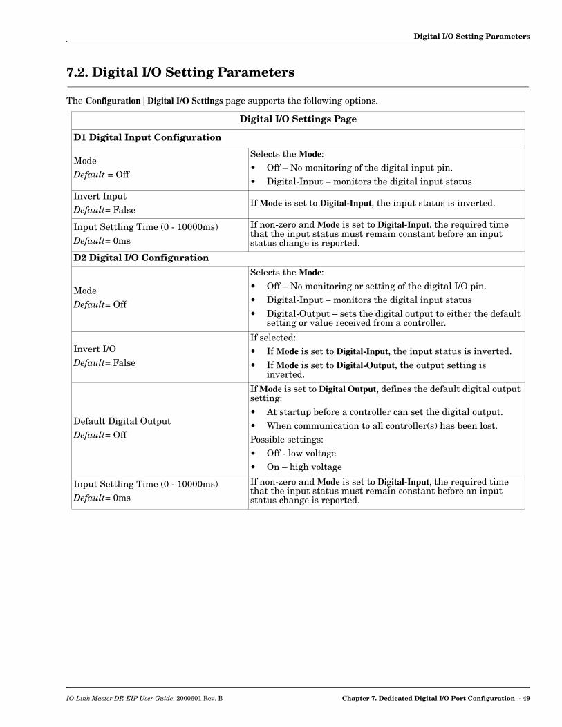
7.2. Digital I/O Setting Parameters
The Configuration | Digital I/O Settings page supports the following options.
Digital I/O Settings Page
D1 Digital Input Configuration
ModeDefault = Off
Selects the Mode:• Off – No monitoring of the digital input pin.• Digital-Input – monitors the digital input status
Invert InputDefault= False
If Mode is set to Digital-Input, the input status is inverted.
Input Settling Time (0 - 10000ms)Default= 0ms
If non-zero and Mode is set to Digital-Input, the required time that the input status must remain constant before an input status change is reported.
D2 Digital I/O Configuration
ModeDefault= Off
Selects the Mode:• Off – No monitoring or setting of the digital I/O pin.• Digital-Input – monitors the digital input status• Digital-Output – sets the digital output to either the default
setting or value received from a controller.
Invert I/ODefault= False
If selected:• If Mode is set to Digital-Input, the input status is inverted.• If Mode is set to Digital-Output, the output setting is
inverted.
Default Digital OutputDefault= Off
If Mode is set to Digital Output, defines the default digital output setting:• At startup before a controller can set the digital output.• When communication to all controller(s) has been lost.Possible settings:• Off - low voltage• On – high voltage
Input Settling Time (0 - 10000ms)Default= 0ms
If non-zero and Mode is set to Digital-Input, the required time that the input status must remain constant before an input status change is reported.
IO-Link Master DR-EIP User Guide: 2000601 Rev. B Chapter 7. Dedicated Digital I/O Port Configuration - 49
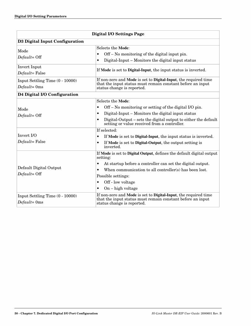
Digital I/O Setting Parameters
D3 Digital Input Configuration
ModeDefault= Off
Selects the Mode:• Off – No monitoring of the digital input pin.• Digital-Input – Monitors the digital input status
Invert InputDefault= False
If Mode is set to Digital-Input, the input status is inverted.
Input Settling Time (0 - 10000)Default= 0ms
If non-zero and Mode is set to Digital-Input, the required time that the input status must remain constant before an input status change is reported.
D4 Digital I/O Configuration
ModeDefault= Off
Selects the Mode:• Off – No monitoring or setting of the digital I/O pin.• Digital-Input – Monitors the digital input status• Digital-Output – sets the digital output to either the default
setting or value received from a controller.
Invert I/ODefault= False
If selected:• If Mode is set to Digital-Input, the input status is inverted.• If Mode is set to Digital-Output, the output setting is
inverted.
Default Digital OutputDefault= Off
If Mode is set to Digital Output, defines the default digital output setting:• At startup before a controller can set the digital output.• When communication to all controller(s) has been lost.Possible settings:• Off - low voltage• On – high voltage
Input Settling Time (0 - 10000)Default= 0ms
If non-zero and Mode is set to Digital-Input, the required time that the input status must remain constant before an input status change is reported.
Digital I/O Settings Page
50 - Chapter 7. Dedicated Digital I/O Port Configuration IO-Link Master DR-EIP User Guide: 2000601 Rev. B

Chapter 8. Loading and Managing IODD Files
There are several Attached Devices pages that support IO-Link Device Description (IODD) file management.• IO-Link Device Description Files Page - load IODD files from the IO-Link device manufacturer.• IO-Link Device Configuration Summary Page on Page 57 - verify the correct files were loaded for each IO-
Link device.• The Port pages are discussed in Chapter 9. Configuring IO-Link Devices on Page 59.
8.1. IO-Link Device Description Files Page
Use the IO-Link Device Description Files page to update (upload) and delete IO-Link Device Description (IODD) files associated with this IOLM DR-8-EIP. In addition, you can review the IODD xml file using the VIEW button after loading the IODD file.Note: You will need to download the appropriate IODD files from your IO-Link device manufacturer.
The IOLM DR-8-EIP provides 15790K of space to store IODD files. The IOLM DR-8-EIP includes the following default IODD files, which cannot be deleted.• IODD-StandardDefinitions1.0.1.xml • IODD-StandardUnitDefinitions1.0.1.xml • IODD-StandardDefinitions1.1.xml • IODD-StandardUnitDefinitions1.1.xml
IO-Link Master DR-EIP User Guide: 2000601 Rev. B Chapter 8. Loading and Managing IODD Files - 51

Preparing IODD Files to Upload
8.1.1. Preparing IODD Files to Upload
After downloading the IODD files for the IO-Link device from the IO-Link sensor or actuator manufacturer, you may need to unzip the file and locate the appropriate xml file for the device.• Some IODD zip files contain the xml files and supporting image files for a single product. This type of zip
file can be immediately loaded onto the IOLM DR-8-EIP.• Some IODD zip files contain the files for multiple products. If you upload this type of IODD zip file, the
IOLM DR-8-EIP loads the first xml file and the associated image files, which may or may not correspond to the IO-Link device connected to the port. If you need to zip the appropriate files, the following information may be useful:- Unzip the package and locate the xml file needed for your IO-Link device. - Open the xml file and search for the productID, which identifies the IO-Link device.- Zip the xml file along with the supporting images. There are several ways to locate the supporting
images:- Locate the appropriate images using the xml file.- Load only the xml file and the IOLM DR-8-EIP notifies you what files are missing. Use the UPDATE
feature to upload the missing images.- Zip the xml with all of the images and the IOLM DR-8-EIP ignores (and not upload) any unused
files and notifies which files did not upload.Note: Image files are not required for IO-Link device configuration.
Use the appropriate discussion for your IODD files.• Uploading IODD Zip Files• Uploading xml Files or Supporting Files on Page 54
52 - Chapter 8. Loading and Managing IODD Files IO-Link Master DR-EIP User Guide: 2000601 Rev. B

Uploading IODD Zip Files
8.1.2. Uploading IODD Zip Files
You can use the following procedure to upload IODD zip files.1. Click Attached Devices and IODD FILES.2. Click the UPLOAD IODD FILE button.3. Click the Browse button.4. Highlight the zip file, click Open and then the UPLOAD button.
Note: Only images referenced in the xml file load to the IOLM DR-8-EIP and the remaining files are ignored.
5. If desired, you can view the xml file by clicking the IODD FILENAME in the table.6. Optionally, verify that the correct xml file was loaded using the Summary page (Page 57).
IO-Link Master DR-EIP User Guide: 2000601 Rev. B Chapter 8. Loading and Managing IODD Files - 53

Uploading xml Files or Supporting Files
8.1.3. Uploading xml Files or Supporting Files
You can use the following procedure to upload xml, or supporting image files. 1. Click Attached Devices and IODD FILES.2. Click the UPLOAD IODD FILE button.3. Click the Browse... button.4. Highlight the xml or image file and click Open.
Note: The xml file must be loaded before the IOLM DR-8-EIP will load the associated image files.5. Click the UPLOAD button.6. Optionally, use the following steps to load image files:
a. Select the row in the table that contains the xml file.
b. Click the UPLOAD IODD FILE button.c. Click the Browse button.d. Highlight the image and click Open.e. Click the UPLOAD button.f. If desired, you can view the xml file by clicking the IODD FILENAME in the table.g. Optionally, verify that the correct xml file was loaded using the Summary page (Page 57).
54 - Chapter 8. Loading and Managing IODD Files IO-Link Master DR-EIP User Guide: 2000601 Rev. B

Viewing and Saving IODD Files
8.1.4. Viewing and Saving IODD Files
Use the following procedure to view the contents of an IODD file.1. If necessary, click Attached Devices and IODD Files.2. Click the IODD FILENAME in the table that you want to review. A pop up window displays the contents of
the IODD file.3. Optionally, click the file name hyperlink at the top of the window to view the formatted file or if you want
to save a copy of the file to another location.
IO-Link Master DR-EIP User Guide: 2000601 Rev. B Chapter 8. Loading and Managing IODD Files - 55

Deleting IODD Files
8.1.5. Deleting IODD Files
Use the following procedure to delete an IODD file set from the IOLM DR-8-EIP.1. If necessary, click Attached Devices and IODD Files.
2. Check the corresponding row of the IODD file that you want to delete.3. Click the DELETE SELECTED button.
4. Click CONTINUE to the Delete files? message.
56 - Chapter 8. Loading and Managing IODD Files IO-Link Master DR-EIP User Guide: 2000601 Rev. B
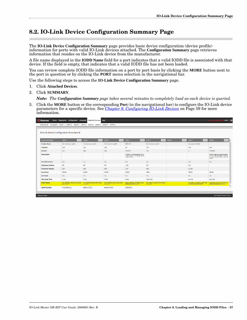
IO-Link Device Configuration Summary Page
8.2. IO-Link Device Configuration Summary Page
The IO-Link Device Configuration Summary page provides basic device configuration (device profile) information for ports with valid IO-Link devices attached. The Configuration Summary page retrieves information that resides on the IO-Link device from the manufacturer. A file name displayed in the IODD Name field for a port indicates that a valid IODD file is associated with that device. If the field is empty, that indicates that a valid IODD file has not been loaded.You can review complete IODD file information on a port by port basis by clicking the MORE button next to the port in question or by clicking the PORT menu selection in the navigational bar.Use the following steps to access the IO-Link Device Configuration Summary page.1. Click Attached Devices.2. Click SUMMARY.
Note: The Configuration Summary page takes several minutes to completely load as each device is queried. 3. Click the MORE button or the corresponding Port (in the navigational bar) to configure the IO-Link device
parameters for a specific device. See Chapter 9. Configuring IO-Link Devices on Page 59 for more information.
IO-Link Master DR-EIP User Guide: 2000601 Rev. B Chapter 8. Loading and Managing IODD Files - 57

IO-Link Device Configuration Summary Page
58 - Chapter 8. Loading and Managing IODD Files IO-Link Master DR-EIP User Guide: 2000601 Rev. B
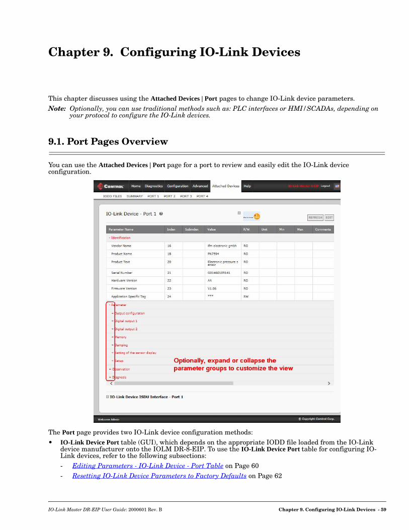
Chapter 9. Configuring IO-Link Devices
This chapter discusses using the Attached Devices | Port pages to change IO-Link device parameters. Note: Optionally, you can use traditional methods such as: PLC interfaces or HMI/SCADAs, depending on
your protocol to configure the IO-Link devices.
9.1. Port Pages Overview
You can use the Attached Devices | Port page for a port to review and easily edit the IO-Link device configuration.
The Port page provides two IO-Link device configuration methods:• IO-Link Device Port table (GUI), which depends on the appropriate IODD file loaded from the IO-Link
device manufacturer onto the IOLM DR-8-EIP. To use the IO-Link Device Port table for configuring IO-Link devices, refer to the following subsections:- Editing Parameters - IO-Link Device - Port Table on Page 60- Resetting IO-Link Device Parameters to Factory Defaults on Page 62
IO-Link Master DR-EIP User Guide: 2000601 Rev. B Chapter 9. Configuring IO-Link Devices - 59
Editing Parameters - IO-Link Device - Port Table
• IO-Link Device ISDU Interface - Port, which can be used with or without IODD files loaded. Refer to the following information to use the IO-Link Device ISDU Interface - Port method:- The IO-Link Device Operator Manual from the device manufacturer is needed to use the IO-Link
Device ISDU Interface since ISDU block index and ISDU sub-index numbers are required. - Editing Parameters - IO-Link Device ISDU Interface - Port on Page 63
9.2. Editing Parameters - IO-Link Device - Port Table
Use the following procedure to edit IO-Link device parameters using the IO-Link Device Port table.Note: You may want to verify that the Automatic Download Enable for Data Storage option on the
Configuration | IO-Link Settings page is NOT set to On as this can cause unreliable results on the corresponding port.
1. If you have not done so, load the IODD file from the IO-Link device manufacturer (Chapter 8. Loading and Managing IODD Files on Page 51).
2. Access the appropriate Port page by clicking Attached Devices and then the Port number that you want to configure.
3. Click the EDIT button after all of the device information is populated in the table. 4. Scroll down the table and make appropriate parameter changes for your environment.
Note: An IODD file may not contain every IO-Link device setting depending on the IO-Link device manufacturer. If you need to change a parameter that is not displayed in the IO-Link Device - Port table, you can refer to the IO-Link device Operators Manual and use the IO-Link Device ISDU Interface to change the settings.
60 - Chapter 9. Configuring IO-Link Devices IO-Link Master DR-EIP User Guide: 2000601 Rev. B
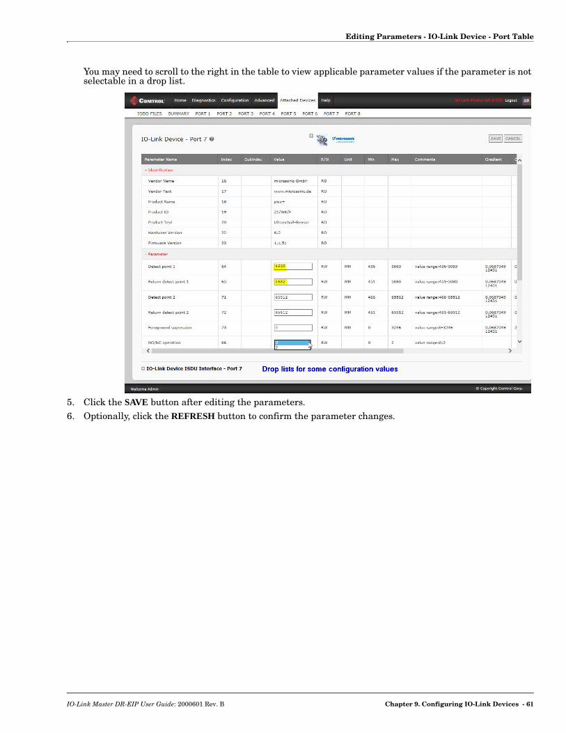
Editing Parameters - IO-Link Device - Port Table
You may need to scroll to the right in the table to view applicable parameter values if the parameter is not selectable in a drop list.
5. Click the SAVE button after editing the parameters.6. Optionally, click the REFRESH button to confirm the parameter changes.
IO-Link Master DR-EIP User Guide: 2000601 Rev. B Chapter 9. Configuring IO-Link Devices - 61

Resetting IO-Link Device Parameters to Factory Defaults
9.3. Resetting IO-Link Device Parameters to Factory Defaults
In the event you want to reset the IO-Link device to factory default, typically the IODD file provides the ability from the IO-Link device manufacturer. Use the following example to reset an IO-Link device.1. Click the EDIT button and locate the Restore Factory button.2. Click the Restore Factory or Load Factory Settings button.
Note: The name of the button is determined by the IO-Link device manufacturer.
3. Click OK when the Command Executed message appears.4. Click Cancel to close the IO-Link Device - Port table.
Note: If you click SAVE, the default values are not loaded.
62 - Chapter 9. Configuring IO-Link Devices IO-Link Master DR-EIP User Guide: 2000601 Rev. B

Editing Parameters - IO-Link Device ISDU Interface - Port
5. Optionally, click the REFRESH button to verify the settings.
9.4. Editing Parameters - IO-Link Device ISDU Interface - Port
The IO-Link Device ISDU Interface follows these guidelines:• If necessary, convert hexadecimal ISDU index numbers to decimal, you must enter the decimal value for
the ISDU Block Index and ISDU Sub-index numbers.• You must enter the hexadecimal value for the IO-Link device parameters.If the appropriate IODD files has been loaded, you can use the IO-Link Device - Port table to determine the index numbers and acceptable values for each parameter. Note: An IODD file may not contain every IO-Link device setting depending on the IO-Link device
manufacturer. If you need to change a parameter that is not displayed in the IO-Link Device - Port table, you can refer to the IO-Link Device Operators Manual.
If an IODD file has not been loaded for an IO-Link device, you can use the IO-Link Device Operator's Manual to determine the ISDU indexes.Please note:• You must enter the decimal value for the ISDU Block Index and ISDU Sub-index.• The GET button retrieves the parameter value in hex from the IO-Link device. You may want to retrieve
values to determine the data length.
• The SET button sends the value to the IO-Link device.
• After successfully changing a parameter, the IO-Link Master responds with a command executed notification.
• This message means that the IO-Link device defines the entry as an invalid setting.
IO-Link Master DR-EIP User Guide: 2000601 Rev. B Chapter 9. Configuring IO-Link Devices - 63

Editing Parameters - IO-Link Device ISDU Interface - Port
• This message indicates that the IO-Link device cannot read the specified ISDU Block Index and Sub-index.
Use the following procedure to edit parameters using the IO-Link Device ISDU Interface - Port.Note: You may want to verify that the Automatic Download Enable for Data Storage option on the
Configuration | IO-Link Settings page is NOT set to On as this can cause unreliable results on the corresponding port.
1. Click the + next to the IO-Link Device ISDU Interface to open the interface.
2. Enter the ISDU Block Index number (decimal) that you want to edit.3. If applicable, enter the ISDU Sub-index (decimal).4. Edit the parameter (hex) and click the SET button.
64 - Chapter 9. Configuring IO-Link Devices IO-Link Master DR-EIP User Guide: 2000601 Rev. B
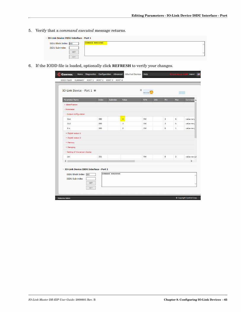
Editing Parameters - IO-Link Device ISDU Interface - Port
5. Verify that a command executed message returns.
6. If the IODD file is loaded, optionally click REFRESH to verify your changes.
IO-Link Master DR-EIP User Guide: 2000601 Rev. B Chapter 9. Configuring IO-Link Devices - 65

Editing Parameters - IO-Link Device ISDU Interface - Port
66 - Chapter 9. Configuring IO-Link Devices IO-Link Master DR-EIP User Guide: 2000601 Rev. B

Chapter 10. Utilizing IOLM DR-8-EIP Features
This chapter discusses using the following features:• Data Storage (automatic and manual) to upload or download IO-Link v1.1 device parameters• Device Validation (identical or compatible) to dedicate a port or ports to specific IO-Link devices• Data Validation (strict or loose) to verify data integrity• Configuration files (save and load) to back up or load the same configuration to multiple IOLM DR-8-
EIP units• Menu Bar Hover Shows Submenu, which provides an option to navigate the submenu structure quickly.
10.1. Data Storage
Data storage is typically supported by IO-Link v1.1 devices. Data storage means that you can upload parameters from an IO-Link device to the IOLM DR-8-EIP and/or download parameters from the IOLM DR-8-EIP to the IO-Link device. This feature can be used to:• Quickly and easily replace a defective IO-Link device• Configure multiple IO-Link devices with the same parameters as fast as it takes to connect and
disconnect the IO-Link deviceTo determine whether an IO-Link (v1.1) device supports data storage, you can check one of the following:• IO-Link Diagnostics page - check the Data Storage Capable field.• IO-Link Configuration page - check to see if UPLOAD and DOWNLOAD buttons display under the Data
Storage Manual Ops group.
10.1.1.Uploading Data Storage to the IOLM DR-8-EIP
The IO-Link device manufacturer determines which parameters are saved for data storage. Remember, the IOL-Link device should be configured before enabling data storage unless you are using data storage to back up the default device configuration.There are two methods to upload Data Storage using the Configuration | IO-Link page:• Automatic Enable Upload - If a port is set to On for this option, the IOLM DR-8-EIP saves the data
storage (if the data storage is empty) from the IO-Link device to that port. Some IO-Link devices update the data storage contents if you use the Teach buttons on the IO-Link device, but that is also determined by the IO-Link device manufacturer.When this option is enabled and another IO-Link device (different Vendor ID and Device ID), the IO-Link Diagnostics page displays a DV: Wrong Sensor in the IOLink State field and the IO-Link port LED flashes red, indicating a hardware fault.Automatic upload occurs when the Automatic Upload Enable option is set to On and one of these conditions exists:• There is no upload data stored on the gateway.• The IO-Link device executes a requests_ at upload function (generally because you have changed the
configuration via Teach buttons).Note: Do not enable both Automatic Upload and Download at the same time, the results are not reliable
among IO-Link device manufacturers.
IO-Link Master DR-EIP User Guide: 2000601 Rev. B Chapter 10. Utilizing IOLM DR-8-EIP Features - 67
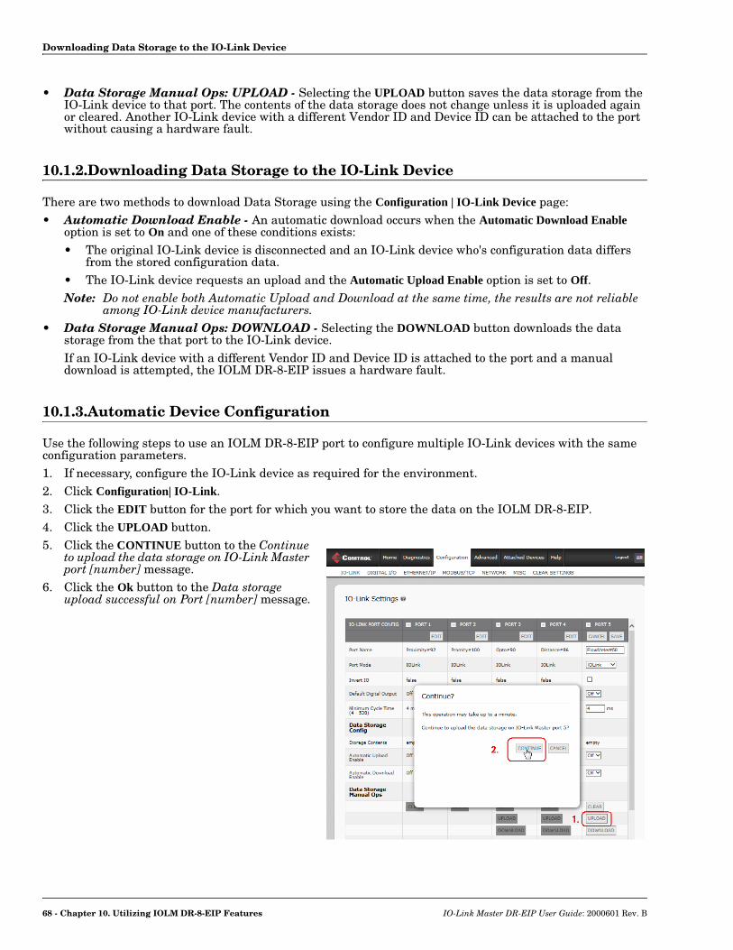
Downloading Data Storage to the IO-Link Device
• Data Storage Manual Ops: UPLOAD - Selecting the UPLOAD button saves the data storage from the IO-Link device to that port. The contents of the data storage does not change unless it is uploaded again or cleared. Another IO-Link device with a different Vendor ID and Device ID can be attached to the port without causing a hardware fault.
10.1.2.Downloading Data Storage to the IO-Link Device
There are two methods to download Data Storage using the Configuration | IO-Link Device page:• Automatic Download Enable - An automatic download occurs when the Automatic Download Enable
option is set to On and one of these conditions exists: • The original IO-Link device is disconnected and an IO-Link device who's configuration data differs
from the stored configuration data.• The IO-Link device requests an upload and the Automatic Upload Enable option is set to Off.Note: Do not enable both Automatic Upload and Download at the same time, the results are not reliable
among IO-Link device manufacturers.• Data Storage Manual Ops: DOWNLOAD - Selecting the DOWNLOAD button downloads the data
storage from the that port to the IO-Link device. If an IO-Link device with a different Vendor ID and Device ID is attached to the port and a manual download is attempted, the IOLM DR-8-EIP issues a hardware fault.
10.1.3.Automatic Device Configuration
Use the following steps to use an IOLM DR-8-EIP port to configure multiple IO-Link devices with the same configuration parameters.1. If necessary, configure the IO-Link device as required for the environment.2. Click Configuration| IO-Link.3. Click the EDIT button for the port for which you want to store the data on the IOLM DR-8-EIP.4. Click the UPLOAD button.5. Click the CONTINUE button to the Continue
to upload the data storage on IO-Link Master port [number] message.
6. Click the Ok button to the Data storage upload successful on Port [number] message.
68 - Chapter 10. Utilizing IOLM DR-8-EIP Features IO-Link Master DR-EIP User Guide: 2000601 Rev. B
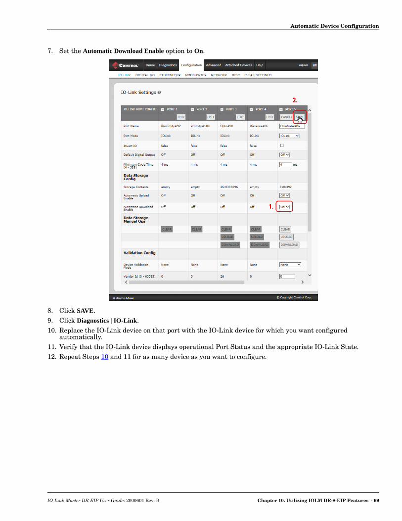
Automatic Device Configuration
7. Set the Automatic Download Enable option to On.
8. Click SAVE.9. Click Diagnostics | IO-Link.10. Replace the IO-Link device on that port with the IO-Link device for which you want configured
automatically.11. Verify that the IO-Link device displays operational Port Status and the appropriate IO-Link State.12. Repeat Steps 10 and 11 for as many device as you want to configure.
IO-Link Master DR-EIP User Guide: 2000601 Rev. B Chapter 10. Utilizing IOLM DR-8-EIP Features - 69

Automatic Device Configuration Backup
10.1.4.Automatic Device Configuration Backup
The following procedure shows how to utilize data storage to automatically backup an IO-Link device configuration.Remember, if you adjust parameters using Teach buttons those values may or not may be updated in the data storage, which depends on the IO-Link device manufacturer. If you are unsure, you can always use the manual UPLOAD feature to capture the latest settings.1. Click Configuration | IO-Link.2. Click the EDIT button for the port for which you want to store the data on the IOLM DR-8-EIP.3. Select On in the drop list for Automatic Data Storage Upload Enable.
4. Click SAVE.When the Configuration | IO-Link page is refreshed, the Storage Contents field displays the Vendor ID and Device ID. In addition, the IO-Link Diagnostics page displays Upload-Only in the Automatic Data Storage Configuration field.
70 - Chapter 10. Utilizing IOLM DR-8-EIP Features IO-Link Master DR-EIP User Guide: 2000601 Rev. B

Device Validation
10.2. Device Validation
Device validation is supported by many IO-Link devices. Device Validation Mode provides these options:• None - this disables Device Validation Mode.• Compatible - permits a compatible IO-Link device (same Vendor ID and Device ID) to function on the
corresponding port.• Identical - only permits an IO-Link device (same Vendor ID, Device ID, and serial number) to function on
the corresponding port.Use this procedure to configure device validation.1. Click Configuration | IO-Link Settings.2. Click the EDIT button.3. Select Compatible or Identical for the Device Validation mode.
Note: Identical Device Validation requires a device serial number to operate.4. Click the GET ATTACHED button or manually complete the Vendor ID, Device, ID, and serial number.
If the device does not have a serial number, you should not select Identical because the IOLM DR-8-EIP requires a serial number to identify a specific device.
5. Click the SAVE button.If the wrong or incompatible device is connected to the port, the IO-Link port LED flashes red and no IO-Link activity occurs on the port until the issue is resolved.
IO-Link Master DR-EIP User Guide: 2000601 Rev. B Chapter 10. Utilizing IOLM DR-8-EIP Features - 71

Data Validation
In addition, the IO-Link Diagnostics page displays the following information.
10.3. Data Validation
You can use this procedure to configure data validation.1. Click Configuration | IO-Link Settings.2. Click the EDIT button on the port you want to configure for data validation.3. Select Loose or Strict to enable data validation.
• Loose - the slave device's PDI/PDO lengths must be less than or equal to the user-configured values.• Strict - the slave device's PDI/PDO lengths must be the same as the user-configured values.
4. Click the GET ATTACHED button or manually enter the PDI and PDO length.
5. Click the SAVE button.If data validation fails, the IO-Link port LED flashes red and the IO-Link Diagnostics page displays an error.
72 - Chapter 10. Utilizing IOLM DR-8-EIP Features IO-Link Master DR-EIP User Guide: 2000601 Rev. B

IOLM DR-8-EIP Configuration Files
10.4. IOLM DR-8-EIP Configuration Files
You can use PortVision DX to save or load IOLM DR-8-EIP configuration files.Note: You must install PortVision DX to save or load IOLM DR-8-EIP configuration files.
10.4.1.Saving Configuration Files
Use this procedure to save configuration files for the IOLM DR-8-EIP. The configuration files includes all port settings, network settings, and encrypted passwords.1. If necessary, open PortVision DX and click the Scan button to locate the IO-Link Master units on your
network.2. Right-click the IOLM DR-8-EIP in the Device List pane (lower pane).3. Click Configuration and Save.4. Browse to a suitable location, enter a file name, and click Save.5. If necessary, enter Admin as the User name and the administrator password.
IO-Link Master DR-EIP User Guide: 2000601 Rev. B Chapter 10. Utilizing IOLM DR-8-EIP Features - 73
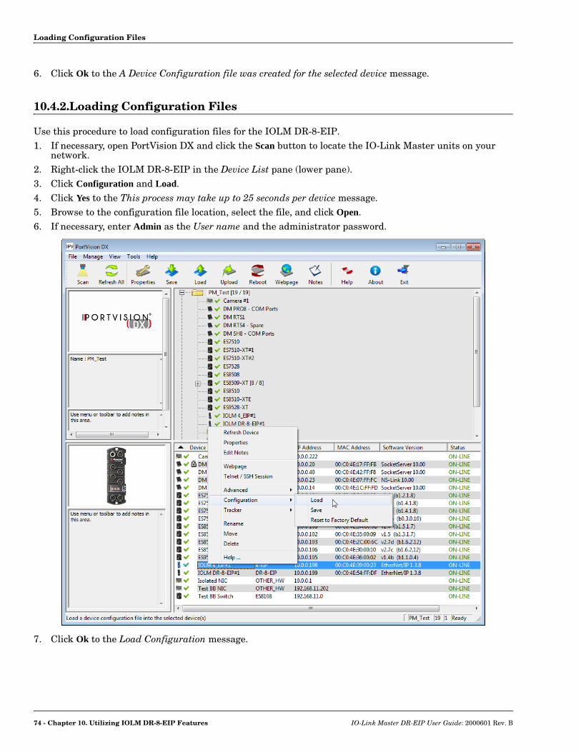
Loading Configuration Files
6. Click Ok to the A Device Configuration file was created for the selected device message.
10.4.2.Loading Configuration Files
Use this procedure to load configuration files for the IOLM DR-8-EIP.1. If necessary, open PortVision DX and click the Scan button to locate the IO-Link Master units on your
network.2. Right-click the IOLM DR-8-EIP in the Device List pane (lower pane).3. Click Configuration and Load.4. Click Yes to the This process may take up to 25 seconds per device message.5. Browse to the configuration file location, select the file, and click Open.6. If necessary, enter Admin as the User name and the administrator password.
7. Click Ok to the Load Configuration message.
74 - Chapter 10. Utilizing IOLM DR-8-EIP Features IO-Link Master DR-EIP User Guide: 2000601 Rev. B
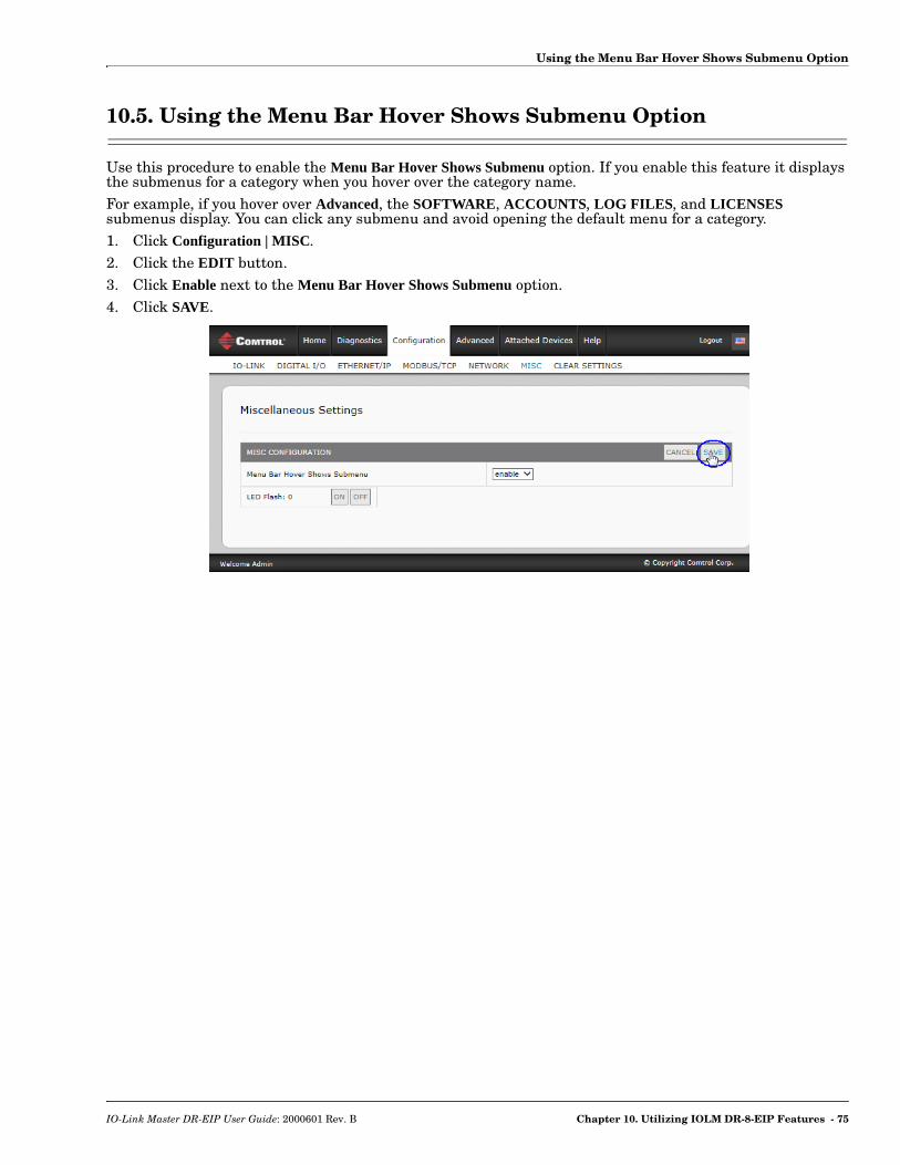
Using the Menu Bar Hover Shows Submenu Option
10.5. Using the Menu Bar Hover Shows Submenu Option
Use this procedure to enable the Menu Bar Hover Shows Submenu option. If you enable this feature it displays the submenus for a category when you hover over the category name.For example, if you hover over Advanced, the SOFTWARE, ACCOUNTS, LOG FILES, and LICENSES submenus display. You can click any submenu and avoid opening the default menu for a category.1. Click Configuration | MISC.2. Click the EDIT button.3. Click Enable next to the Menu Bar Hover Shows Submenu option.4. Click SAVE.
IO-Link Master DR-EIP User Guide: 2000601 Rev. B Chapter 10. Utilizing IOLM DR-8-EIP Features - 75

Using the Menu Bar Hover Shows Submenu Option
76 - Chapter 10. Utilizing IOLM DR-8-EIP Features IO-Link Master DR-EIP User Guide: 2000601 Rev. B
Chapter 11. Using the Diagnostics Pages
This chapter provides information about the following Diagnostics pages.• IO-Link Port Diagnostics• Digital I/O Diagnostics on Page 82• EtherNet/IP Diagnostics on Page 83• Modbus/TCP Diagnostics on Page 87
IO-Link Master DR-EIP User Guide: 2000601 Rev. B Chapter 11. Using the Diagnostics Pages - 77
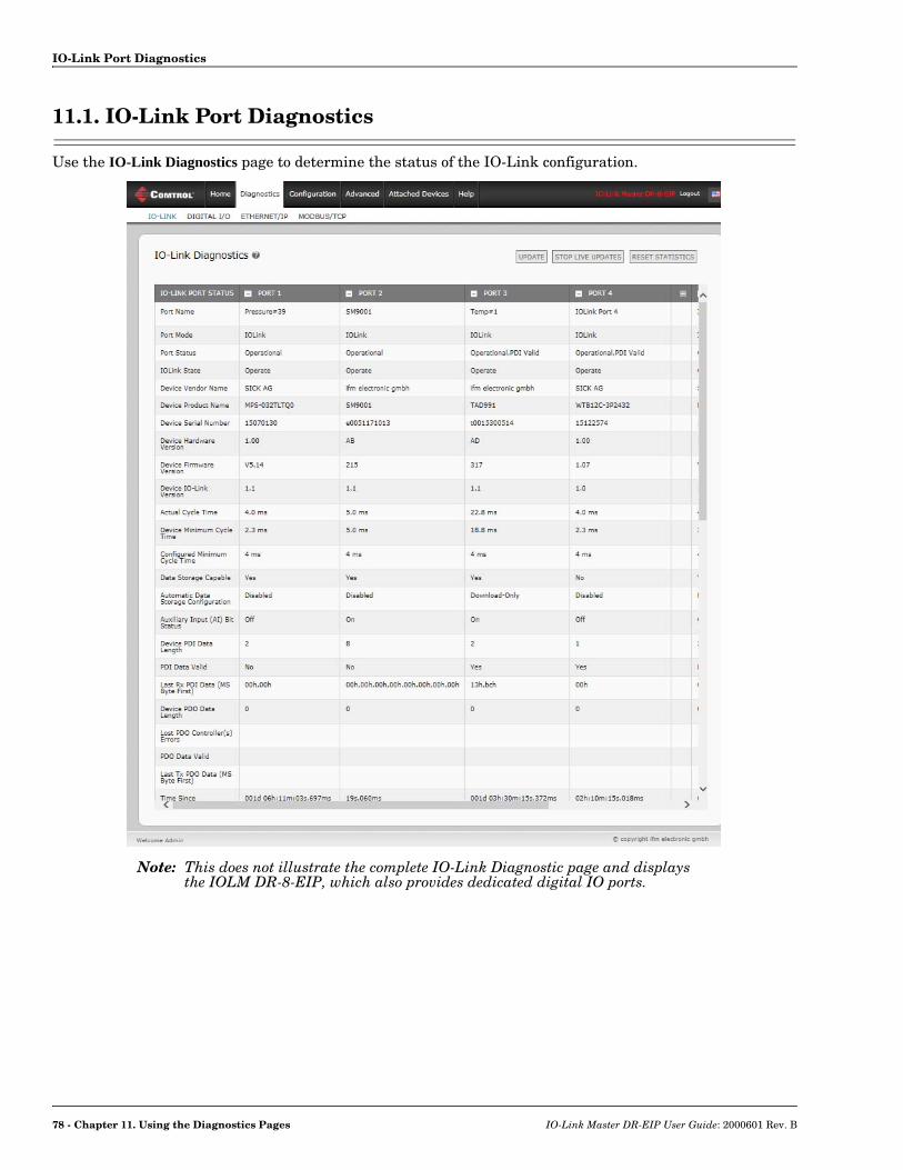
IO-Link Port Diagnostics
11.1. IO-Link Port Diagnostics
Use the IO-Link Diagnostics page to determine the status of the IO-Link configuration.
Note: This does not illustrate the complete IO-Link Diagnostic page and displays the IOLM DR-8-EIP, which also provides dedicated digital IO ports.
78 - Chapter 11. Using the Diagnostics Pages IO-Link Master DR-EIP User Guide: 2000601 Rev. B
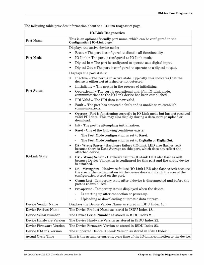
IO-Link Port Diagnostics
The following table provides information about the IO-Link Diagnostics page.
IO-Link Diagnostics
Port Name This is an optional friendly port name, which can be configured in the Configuration | IO-Link page.
Port Mode
Displays the active device mode:• Reset = The port is configured to disable all functionality.• IO-Link = The port is configured to IO-Link mode.• Digital In = The port is configured to operate as a digital input.• Digital Out = The port is configured to operate as a digital output.
Port Status
Displays the port status:• Inactive = The port is in active state. Typically, this indicates that the
device is either not attached or not detected.• Initializing = The port is in the process of initializing.• Operational = The port is operational and, if in IO-Link mode,
communications to the IO-Link device has been established.• PDI Valid = The PDI data is now valid.• Fault = The port has detected a fault and is unable to re-establish
communications.
IO-Link State
• Operate - Port is functioning correctly in IO-Link mode but has not received valid PDI data. This may also display during a data storage upload or download.
• Init - The port is attempting initialization.• Reset - One of the following conditions exists:
- The Port Mode configuration is set to Reset.- The Port Mode configuration is set to DigitalIn or DigitalOut.
• DS - Wrong Sensor - Hardware failure (IO-Link LED also flashes red) because there is Data Storage on this port, which does not reflect the attached device.
• DV - Wrong Sensor - Hardware failure (IO-Link LED also flashes red) because Device Validation is configured for this port and the wrong device is attached.
• DS - Wrong Size - Hardware failure (IO-Link LED also flashes red) because the size of the configuration on the device does not match the size of the configuration stored on the port.
• Comm Lost - Temporary state after a device is disconnected and before the port is re-initialized.
• Pre-operate - Temporary status displayed when the device:- Is starting up after connection or power-up.- Uploading or downloading automatic data storage.
Device Vendor Name Displays the Device Vendor Name as stored in ISDU Index 16.
Device Product Name The Device Product Name as stored in ISDU Index 18.
Device Serial Number The Device Serial Number as stored in ISDU Index 21.
Device Hardware Version The Device Hardware Version as stored in ISDU Index 22.
Device Firmware Version The Device Firmware Version as stored in ISDU Index 23.
Device IO-Link Version The supported Device IO-Link Version as stored in ISDU Index 0.
Actual Cycle Time This is the actual, or current, cycle time of the IO-Link connection to the device.
IO-Link Master DR-EIP User Guide: 2000601 Rev. B Chapter 11. Using the Diagnostics Pages - 79

IO-Link Port Diagnostics
Device Minimum Cycle Time
This is the minimum, or fastest, cycle time supported by the connected IO-Link device.
Configured Minimum Cycle Time
Configured in the Configuration | IO-Link page, this is the minimum cycle time the IO-Link Master will allow the port to operate at. The Actual Cycle Time, which is negotiated between the IO-Link Master and the device, will be at least as long as the greater of the Configured Minimum Cycle Time and the Device Minimum Cycle Time.
Data Storage Capable Displays whether the IO-Link device on a port supports the data storage feature. Not all IO-Link devices support the data storage feature.
Automatic Data Storage Configuration
Displays whether a port is configured to automatically upload data from the IO-Link device or download data from the IOLM DR-8-EIP to the IO-Link device.
Auxiliary Input (AI) Bit Status The current status of the auxiliary bit as received on DI of the IO-Link port.
Device PDI Data Length The supported Device PDI Data Length, in bytes, as stored in ISDU Index 0.
PDI Data Valid Current status of PDI data as received from the IO-Link device.
Last Rx PDI Data (MS Byte First) The last Rx PDI data as received from the IO-Link device.
Device PDO Data Length The supported Device PDO Data Length, in bytes, as stored in ISDU Index 0.
Lost PDO Controller(s) Errors
The number of times that the PDO controller(s) were present and then lost connection.
PDO Data Valid Status of PDO data being received from controller(s).
Last Tx PDO Data (MS Byte First The last Tx PDO data.
Time Since Initialization The time since the last port initialization.
Lost Communication Count The number of times that communication has been lost to the IO-Link device.
Initialization Attempts The number of times the IO-Link port was initialized.
Initialization Errors The number of port initialization errors that occurred.
Process Data Errors The number of process data errors the port received.
Process Data Retries The number of process data retries the port performed.
Internal Communication Errors
The number of IO-Link Master internal communication errors that occurred on this port.
Device Communication Errors The number of device specific communication errors that occurred.
Total Events The total number of events that were received on this port.
First Events Up to the first, or oldest, three events that were received on this port.
Last Events Up to the last, or most recent, three events that were received on this port.
ISDU Statistics
ISDU Read Cmd Attempts The number of read ISDU command attempts.
ISDU Read Cmd Errors The number of read ISDU command errors.
Minimum ISDU Read Cmd Resp Time The minimum, or shortest, read ISDU command response time.
Maximum ISDU Read Cmd Resp Time The maximum, or longest, read ISDU command response time.
IO-Link Diagnostics (Continued)
80 - Chapter 11. Using the Diagnostics Pages IO-Link Master DR-EIP User Guide: 2000601 Rev. B

IO-Link Port Diagnostics
Average ISDU Read Cmd Resp Time The average ISDU read command response time.
Average ISDU Read Cmd Byte Time The average per-byte read ISDU command response time.
ISDU Write Cmd Attempts The number of write ISDU command attempts.
ISDU Write Cmd Errors The number of write ISDU command errors.
Minimum ISDU Write Cmd Resp Time The minimum, or shortest, write ISDU command response time.
Maximum ISDU Write Cmd Resp Time The maximum, or longest, write ISDU command response time.
Average ISDU Write Cmd Resp Time The average ISDU write command response time.
Average ISDU Write Cmd Byte Time The average per-byte ISDU write command response time.
IO-Link Diagnostics (Continued)
IO-Link Master DR-EIP User Guide: 2000601 Rev. B Chapter 11. Using the Diagnostics Pages - 81
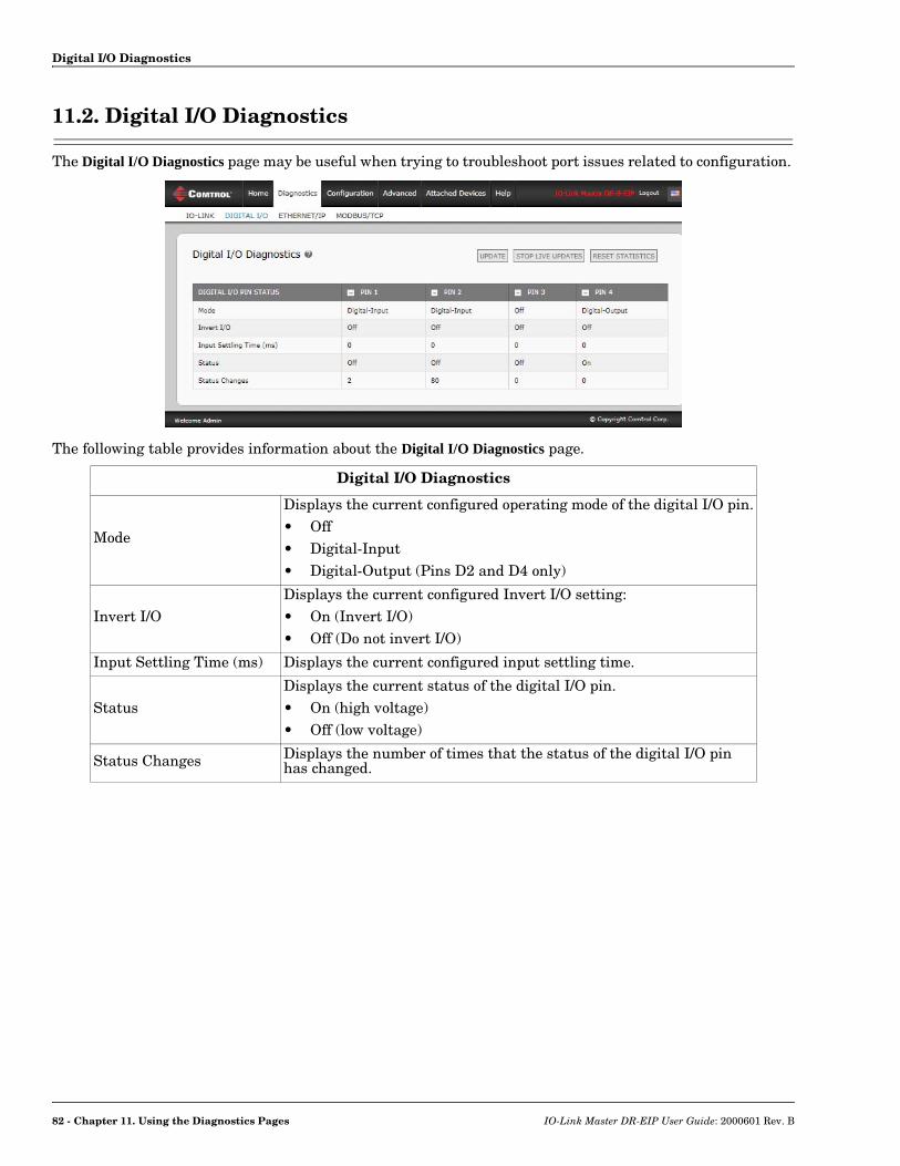
Digital I/O Diagnostics
11.2. Digital I/O Diagnostics
The Digital I/O Diagnostics page may be useful when trying to troubleshoot port issues related to configuration.
The following table provides information about the Digital I/O Diagnostics page.
Digital I/O Diagnostics
Mode
Displays the current configured operating mode of the digital I/O pin.• Off• Digital-Input• Digital-Output (Pins D2 and D4 only)
Invert I/ODisplays the current configured Invert I/O setting:• On (Invert I/O)• Off (Do not invert I/O)
Input Settling Time (ms) Displays the current configured input settling time.
StatusDisplays the current status of the digital I/O pin.• On (high voltage)• Off (low voltage)
Status Changes Displays the number of times that the status of the digital I/O pin has changed.
82 - Chapter 11. Using the Diagnostics Pages IO-Link Master DR-EIP User Guide: 2000601 Rev. B

EtherNet/IP Diagnostics
11.3. EtherNet/IP Diagnostics
The EtherNet/IP Diagnostics page may be useful when trying to troubleshoot EtherNet/IP communications and port issues related to EtherNet/IP configuration.
The following table provides information about the EtherNet/IP Diagnostics page.
EtherNet/IP Diagnostics
Active Session Count
The number of active Ethernet/IP sessions. A session can:• Support both Class 1 I/O and Class 3 Messages• Can be initiated by either the PLC or the IO-Link Master• Can be terminated by either the PLC or the IO-Link Master
Active Connections The current number of active connections (both Class 1 and 3).
Total Connections Established The total number of connections that have been established.
Connection Timeouts The number of connections that have closed due to timing out.
Connections Closed The number connections that have closed due to a standard processes.
Note: This does not illustrate the complete EtherNet/IP Diagnostics page. The image displays an IOLM DR-8-EIP, which provides dedicated digital IO ports.
IO-Link Master DR-EIP User Guide: 2000601 Rev. B Chapter 11. Using the Diagnostics Pages - 83
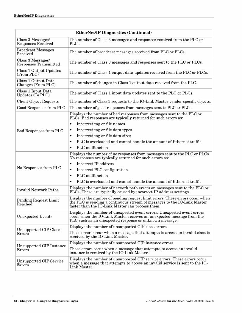
EtherNet/IP Diagnostics
Class 3 Messages/Responses Received
The number of Class 3 messages and responses received from the PLC or PLCs.
Broadcast Messages Received The number of broadcast messages received from PLC or PLCs.
Class 3 Messages/Responses Transmitted The number of Class 3 messages and responses sent to the PLC or PLCs.
Class 1 Output Updates (From PLC) The number of Class 1 output data updates received from the PLC or PLCs.
Class 1 Output Data Changes (From PLC) The number of changes in Class 1 output data received from the PLC.
Class 1 Input Data Updates (To PLC) The number of Class 1 input data updates sent to the PLC or PLCs.
Client Object Requests The number of Class 3 requests to the IO-Link Master vendor specific objects.
Good Responses from PLC The number of good responses from messages sent to PLC or PLCs.
Bad Responses from PLC
Displays the number of bad responses from messages sent to the PLC or PLCs. Bad responses are typically returned for such errors as:• Incorrect tag or file names• Incorrect tag or file data types• Incorrect tag or file data sizes• PLC is overloaded and cannot handle the amount of Ethernet traffic• PLC malfunction
No Responses from PLC
Displays the number of no responses from messages sent to the PLC or PLCs. No responses are typically returned for such errors as:• Incorrect IP address• Incorrect PLC configuration• PLC malfunction• PLC is overloaded and cannot handle the amount of Ethernet traffic
Invalid Network Paths Displays the number of network path errors on messages sent to the PLC or PLCs. These are typically caused by incorrect IP address settings.
Pending Request Limit Reached
Displays the number of pending request limit errors. These errors occur when the PLC is sending a continuous stream of messages to the IO-Link Master faster than the IO-Link Master can process them.
Unexpected EventsDisplays the number of unexpected event errors. Unexpected event errors occur when the IO-Link Master receives an unexpected message from the PLC such as an unexpected response or unknown message.
Unsupported CIP Class Errors
Displays the number of unsupported CIP class errors.These errors occur when a message that attempts to access an invalid class is received by the IO-Link Master.
Unsupported CIP Instance Errors
Displays the number of unsupported CIP instance errors.These errors occur when a message that attempts to access an invalid instance is received by the IO-Link Master.
Unsupported CIP Service Errors
Displays the number of unsupported CIP service errors. These errors occur when a message that attempts to access an invalid service is sent to the IO-Link Master.
EtherNet/IP Diagnostics (Continued)
84 - Chapter 11. Using the Diagnostics Pages IO-Link Master DR-EIP User Guide: 2000601 Rev. B

EtherNet/IP Diagnostics
Unsupported CIP Attribute Errors
Displays the number of unsupported CIP request attribute errors. These errors occur when a message that attempts to access an invalid attribute is sent to the IO-Link Master.
Unsupported File Errors Displays the number of messages from SLC/PLC-5/MicroLogix PLCs that attempt to access an unsupported file address.
System Resource Errors
Displays the number of system resource errors. These errors indicate a system error on the IO-Link Master such as operating system errors or full message queues. These errors typically occur when the PLC or PLCs are sending messages to the IO-Link Master faster than the IO-Link Master can process them.
First Error String Text description of the first error that occurred.
Last Error String Text description of the last error that occurred.
EtherNet/IP Port Specific Diagnostics
Configuration ErrorsDisplays the number of improper configuration errors. These errors occur when the IO-Link Master receives a message that cannot be performed due to an invalid configuration.
Invalid Data ErrorsDisplays the number of invalid message data errors. These errors occur when the IO-Link Master receives a message that cannot be performed due to invalid data.
Active PDO Controller(s) Lists the controller interface(s) type, (Class 1 or Class 3), and IP address that are controlling the PDO data.
PDO Writes to Offline or Read-Only Ports
Displays the number of PDO write messages that were dropped due to any of the following:• The port is configured in IO-Link mode:
- There is no device connected to the port.- The IO-Link device is off-line.- The IO-Link device does not support PDO data.
• The PDO Transmit Mode (To PLC) is disabled.• The port is configured in Digital Input mode.
Undeliverable PDI Updates (To PLC)
Displays the number of PDI update messages that could not be delivered to the PLC in the Write-to-Tag/File method. Undeliverable updates may result when:The IO-Link Master cannot complete an Ethernet connection to the PLC.The PDI data is changing faster than the Maximum PLC Update Rate.
ISDU Request Msgs From PLC(s)
Displays the number of ISDU request messages received from the PLC(s) or other controllers. These request messages may contain one or multiple ISDU commands.
ISDU Invalid Requests Displays the number of ISDU requests received over EtherNet/IP with one or more invalid commands.
ISDU Requests When Port Offline
Displays the number of ISDU requests received over EtherNet/IP when the IO-Link port was offline. This can occur when:• The IO-Link port is initializing, such as after start-up.• There is no IO-Link device attached to the port.• The IO-Link device is not responding.• Communication to the IO-Link device has been lost.
EtherNet/IP Diagnostics (Continued)
IO-Link Master DR-EIP User Guide: 2000601 Rev. B Chapter 11. Using the Diagnostics Pages - 85
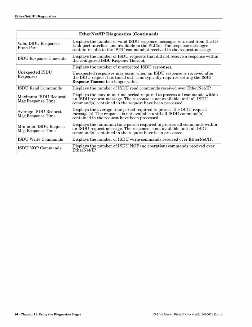
EtherNet/IP Diagnostics
Valid ISDU Responses From Port
Displays the number of valid ISDU response messages returned from the IO-Link port interface and available to the PLC(s). The response messages contain results to the ISDU command(s) received in the request message.
ISDU Response Timeouts Displays the number of ISDU requests that did not receive a response within the configured ISDU Response Timeout.
Unexpected ISDU Responses
Displays the number of unexpected ISDU responses. Unexpected responses may occur when an ISDU response is received after the ISDU request has timed out. This typically requires setting the ISDU Response Timeout to a longer value.
ISDU Read Commands Displays the number of ISDU read commands received over EtherNet/IP.
Maximum ISDU Request Msg Response Time
Displays the maximum time period required to process all commands within an ISDU request message. The response is not available until all ISDU command(s) contained in the request have been processed.
Average ISDU Request Msg Response Time
Displays the average time period required to process the ISDU request message(s). The response is not available until all ISDU command(s) contained in the request have been processed.
Minimum ISDU Request Msg Response Time
Displays the minimum time period required to process all commands within an ISDU request message. The response is not available until all ISDU command(s) contained in the request have been processed.
ISDU Write Commands Displays the number of ISDU write commands received over EtherNet/IP.
ISDU NOP Commands Displays the number of ISDU NOP (no operation) commands received over EtherNet/IP.
EtherNet/IP Diagnostics (Continued)
86 - Chapter 11. Using the Diagnostics Pages IO-Link Master DR-EIP User Guide: 2000601 Rev. B

Modbus/TCP Diagnostics
11.4. Modbus/TCP Diagnostics
The Modbus/TCP Diagnostics page may be useful when trying to troubleshoot Modbus/TCP communications or port issues related to Modbus/TCP configuration.
The following table provides information about the Modbus/TCP Diagnostics page.
Modbus/TCP Diagnostics
Active Connections Displays the current number of active Modbus/TCP connections.
Messages Received from Masters
Displays the number of Modbus messages received from Modbus/TCP Masters.
Responses Sent to Masters Displays the number of Modbus responses sent to Modbus/TCP Masters.
Broadcasts Received Displays the number of broadcast Modbus/TCP messages received.
Invalid Message Length Errors
Displays the number of Modbus messages received with incorrect length fields.
Invalid Message Data ErrorsDisplays the number of invalid message data errors. These errors occur when the IO-Link Master receives a message that cannot be performed due to invalid data.
Note: This image does not illustrate the complete Modbus/TCP Diagnostics page. This displays an IOLM DR-8-EIP, which includes dedicated digital IO ports.
IO-Link Master DR-EIP User Guide: 2000601 Rev. B Chapter 11. Using the Diagnostics Pages - 87

Modbus/TCP Diagnostics
Invalid Message Address Errors
Displays the number of invalid message address errors. These errors occur when the IO-Link Master receives a message that cannot be performed due to an invalid address.
Unknown Device ID ErrorsDisplays the number of unknown device ID errors. These errors occur when the IO-Link Master receives a message that is addressed to a device ID other than the configured Slave Mode Device ID.
Invalid Protocol Type ErrorsDisplays the number of invalid message protocol type errors. These errors occur when the IO-Link Master receives a Modbus/TCP message that specifies a non-Modbus protocol.
Unsupported Function Code Errors
Displays the number of invalid Modbus function code errors. These errors occur when the IO-Link Master receives a message that cannot be performed due to an unsupported Modbus function code.
Configuration ErrorsDisplays the number of improper configuration errors. These errors occur when the IO-Link Master receives a message that cannot be performed due to an invalid configuration.
No Available Connection Errors
Displays the number of Modbus/TCP connection attempts that were rejected due to no available connections. This occurs when the number of Modbus/TCP connections has reached the limit.
System Resource Errors
Displays the number of system resource errors. These errors indicate a system error on the IO-Link such as operating system errors or full message queues. These errors typically occur when the PLC(s) are sending messages to the IO-Link Master faster than the IO-Link Master can process them.
First Error String Text description of the first error that occurred.
Last Error String Text description of the last error that occurred.
Modbus/TCP Port Specific Diagnostics
Active PDO Controller(s) Lists the controller interface(s) type, (Class 1 or Class 3), and IP address that are controlling the PDO data.
PDO Writes to Offline or Read-Only Ports
Displays the number of PDO write messages that were dropped due to any of the following:• The port is configured in IO-Link mode:
- There is no device connected to the port.- The IO-Link device is off-line.- The IO-Link device does not support PDO data.
• The PDO Transmit Mode (To PLC) is disabled.• The port is configured in Digital Input mode.
ISDU Request Msgs From PLC(s)
Displays the number of ISDU request messages received from the PLC(s) or other controllers. These request messages may contain one or multiple ISDU commands.
ISDU Invalid Requests Displays the number of ISDU requests received over Modbus/TCP with one or more invalid commands.
ISDU Requests When Port Offline
Displays the number of ISDU requests received over Modbus/TCP when the IO-Link port was offline. This can occur when:• The IO-Link port is initializing, such as after start-up.• There is no IO-Link device attached to the port.• The IO-Link device is not responding.• Communication to the IO-Link device has been lost.
Modbus/TCP Diagnostics (Continued)
88 - Chapter 11. Using the Diagnostics Pages IO-Link Master DR-EIP User Guide: 2000601 Rev. B
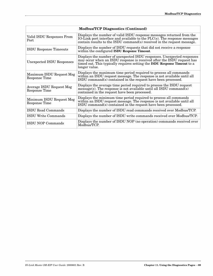
Modbus/TCP Diagnostics
Valid ISDU Responses From Port
Displays the number of valid ISDU response messages returned from the IO-Link port interface and available to the PLC(s). The response messages contain results to the ISDU command(s) received in the request message.
ISDU Response Timeouts Displays the number of ISDU requests that did not receive a response within the configured ISDU Response Timeout.
Unexpected ISDU ResponsesDisplays the number of unexpected ISDU responses. Unexpected responses may occur when an ISDU response is received after the ISDU request has timed out. This typically requires setting the ISDU Response Timeout to a longer value.
Maximum ISDU Request Msg Response Time
Displays the maximum time period required to process all commands within an ISDU request message. The response is not available until all ISDU command(s) contained in the request have been processed.
Average ISDU Request Msg Response Time
Displays the average time period required to process the ISDU request message(s). The response is not available until all ISDU command(s) contained in the request have been processed.
Minimum ISDU Request Msg Response Time
Displays the minimum time period required to process all commands within an ISDU request message. The response is not available until all ISDU command(s) contained in the request have been processed.
ISDU Read Commands Displays the number of ISDU read commands received over Modbus/TCP.
ISDU Write Commands Displays the number of ISDU write commands received over Modbus/TCP.
ISDU NOP Commands Displays the number of ISDU NOP (no operation) commands received over Modbus/TCP.
Modbus/TCP Diagnostics (Continued)
IO-Link Master DR-EIP User Guide: 2000601 Rev. B Chapter 11. Using the Diagnostics Pages - 89

Modbus/TCP Diagnostics
90 - Chapter 11. Using the Diagnostics Pages IO-Link Master DR-EIP User Guide: 2000601 Rev. B
Chapter 12. Troubleshooting and Technical Support
This chapter provides the following information:• Troubleshooting• Contacting Technical Support on Page 93• Using Log Files on Page 94
12.1. Troubleshooting
Before contacting Technical Support, you may want to try the following:• Check to make sure LEDs are not reporting an issue using IOLM DR-8-EIP LEDs on Page 92.• Verify that the network IP address, subnet mask, and gateway are correct and appropriate for the
network. Make sure that the IP address programmed into the IO-Link Master matches the unique reserved IP configured address assigned by the system administrator.- If using DHCP, the host system needs to provide the subnet mask. The gateway is optional and is not
required for a purely local network.- Verify that the Ethernet hub and any other network devices between the system and the IO-Link
Master are powered up and operating.• Verify that you are using the correct types of cables on the correct connectors and that all cables are
connected securely.• Disconnect and re-connect the IO-Link device, or optionally, use the Configuration | IO-Link page to Reset
the port, and then set the Port Mode back to IOLink.• Reboot or power cycle the IOLM DR-8-EIP. Use the Advanced | Software page to reboot the IOLM DR-8-
EIP.• Verify that the Port Mode matches the device, for example: IO-Link, Digital In, Digital Out, or Reset (port
is disabled).• If you are receiving an error that indicates a hardware fault, check the Configuration | IO-Link page for the
port experiencing the fault. - Check the settings for the Automatic Upload Enable and Automatic Download Enable options. If the
Vendor ID or Device ID of the attached device does not match, a hardware fault is generated.- Make sure if the port contains data storage that the Vendor ID and Device ID match the device
attached to the port. If it does not, CLEAR the data storage or move the device to another port.- Check the Device Validation and Data Validation settings. If the attached device does not meet these
settings, a hardware fault is issued.• Open the IO-Link Master web interface and review the following pages to see if you can locate a problem:
- IO-Link Diagnostics
- Digital I/O Diagnostics
- EtherNet/IP Diagnostics
- Modbus/TCP Diagnostics
• If you have a spare IO-Link Master, try replacing the IO-Link Master.
IO-Link Master DR-EIP User Guide: 2000601 Rev. B Chapter 12. Troubleshooting and Technical Support - 91
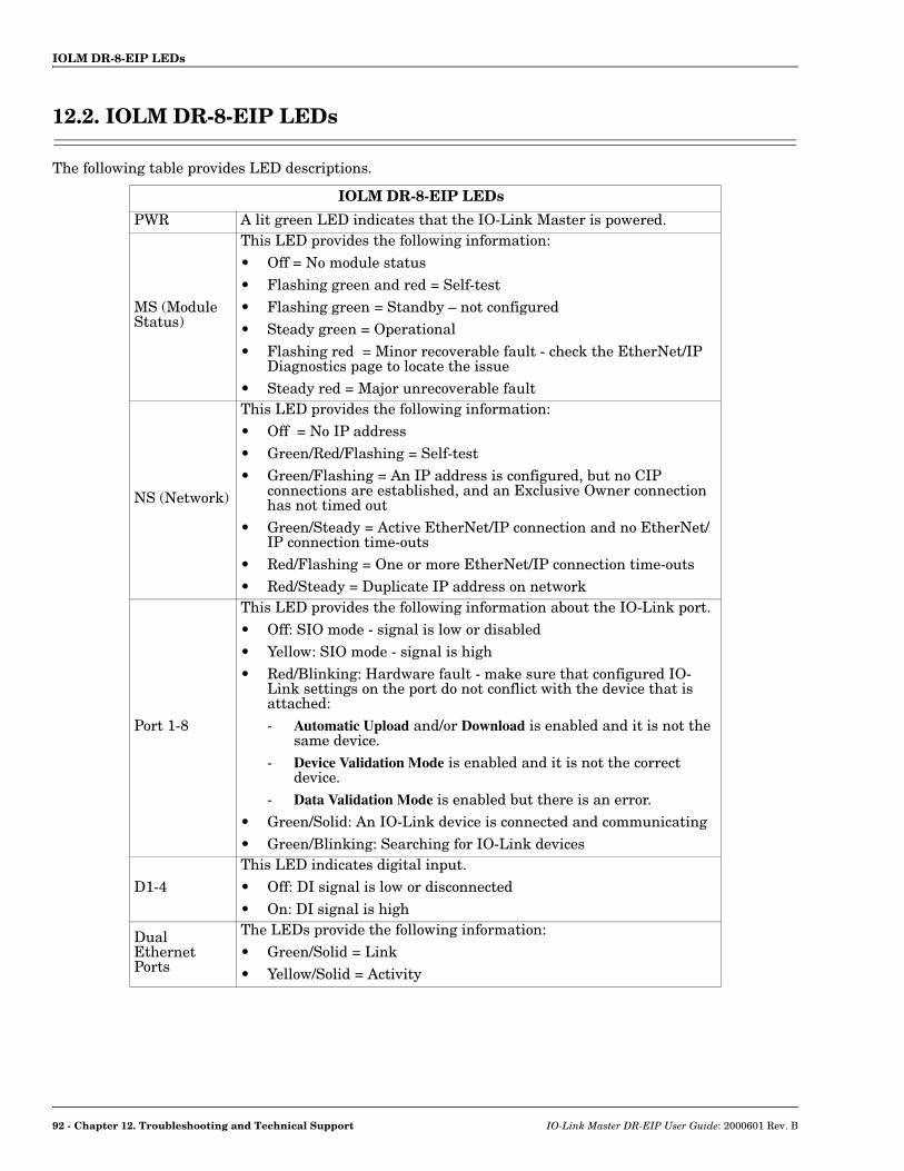
IOLM DR-8-EIP LEDs
12.2. IOLM DR-8-EIP LEDs
The following table provides LED descriptions.
IOLM DR-8-EIP LEDs
PWR A lit green LED indicates that the IO-Link Master is powered.
MS (Module Status)
This LED provides the following information:• Off = No module status • Flashing green and red = Self-test • Flashing green = Standby – not configured • Steady green = Operational• Flashing red = Minor recoverable fault - check the EtherNet/IP
Diagnostics page to locate the issue• Steady red = Major unrecoverable fault
NS (Network)
This LED provides the following information:• Off = No IP address • Green/Red/Flashing = Self-test • Green/Flashing = An IP address is configured, but no CIP
connections are established, and an Exclusive Owner connection has not timed out
• Green/Steady = Active EtherNet/IP connection and no EtherNet/IP connection time-outs
• Red/Flashing = One or more EtherNet/IP connection time-outs • Red/Steady = Duplicate IP address on network
Port 1-8
This LED provides the following information about the IO-Link port. • Off: SIO mode - signal is low or disabled• Yellow: SIO mode - signal is high• Red/Blinking: Hardware fault - make sure that configured IO-
Link settings on the port do not conflict with the device that is attached:- Automatic Upload and/or Download is enabled and it is not the
same device.- Device Validation Mode is enabled and it is not the correct
device.- Data Validation Mode is enabled but there is an error.
• Green/Solid: An IO-Link device is connected and communicating• Green/Blinking: Searching for IO-Link devices
D1-4This LED indicates digital input.• Off: DI signal is low or disconnected• On: DI signal is high
Dual Ethernet Ports
The LEDs provide the following information:• Green/Solid = Link • Yellow/Solid = Activity
92 - Chapter 12. Troubleshooting and Technical Support IO-Link Master DR-EIP User Guide: 2000601 Rev. B
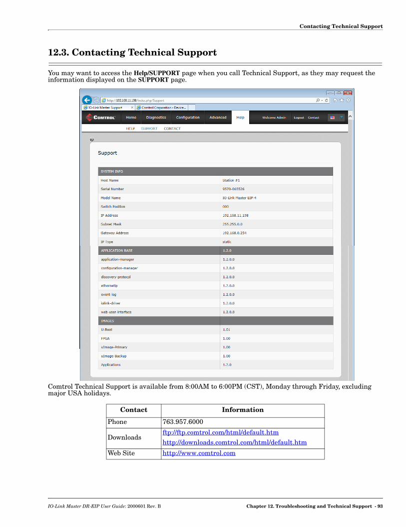
Contacting Technical Support
12.3. Contacting Technical Support
You may want to access the Help/SUPPORT page when you call Technical Support, as they may request the information displayed on the SUPPORT page.
Comtrol Technical Support is available from 8:00AM to 6:00PM (CST), Monday through Friday, excluding major USA holidays.
Contact Information
Phone 763.957.6000
Downloadsftp://ftp.comtrol.com/html/default.htm http://downloads.comtrol.com/html/default.htm
Web Site http://www.comtrol.com
IO-Link Master DR-EIP User Guide: 2000601 Rev. B Chapter 12. Troubleshooting and Technical Support - 93
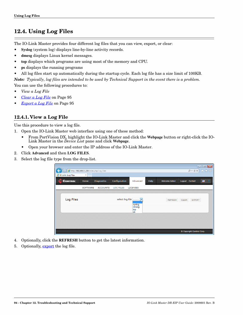
Using Log Files
12.4. Using Log Files
The IO-Link Master provides four different log files that you can view, export, or clear:• Syslog (system log) displays line-by-line activity records. • dmesg displays Linux kernel messages.• top displays which programs are using most of the memory and CPU.• ps displays the running programs• All log files start up automatically during the startup cycle. Each log file has a size limit of 100KB.Note: Typically, log files are intended to be used by Technical Support in the event there is a problem.You can use the following procedures to:• View a Log File• Clear a Log File on Page 95• Export a Log File on Page 95
12.4.1. View a Log File
Use this procedure to view a log file.1. Open the IO-Link Master web interface using one of these method:
• From PortVision DX, highlight the IO-Link Master and click the Webpage button or right-click the IO-Link Master in the Device List pane and click Webpage.
• Open your browser and enter the IP address of the IO-Link Master.2. Click Advanced and then LOG FILES.3. Select the log file type from the drop-list.
4. Optionally, click the REFRESH button to get the latest information.5. Optionally, export the log file.
94 - Chapter 12. Troubleshooting and Technical Support IO-Link Master DR-EIP User Guide: 2000601 Rev. B

Clear a Log File
12.4.2. Clear a Log File
Use this procedure to clear a log file.1. Open the IO-Link Master web interface using one of these method:
• From PortVision DX, highlight the IO-Link Master and click the Webpage button or right-click the IO-Link Master in the Device List pane and click Webpage.
• Open your browser and enter the IP address of the IO-Link Master.2. Click Advanced and then LOG FILES.3. Optionally, export the log file.4. Select the log file type from the drop-list.5. Click the CLEAR button.
The log file automatically starts logging the latest information.
12.4.3. Export a Log File
Use the following procedure to export a log file.1. Open the IO-Link Master web interface using one of these method:
• From PortVision DX, highlight the IO-Link Master and click the Webpage button or right-click the IO-Link Master in the Device List pane and click Webpage.
• Open your browser and enter the IP address of the IO-Link Master.2. Click Advanced and then LOG FILES.3. Select the log file type from the drop-list.4. Click the EXPORT button.
IO-Link Master DR-EIP User Guide: 2000601 Rev. B Chapter 12. Troubleshooting and Technical Support - 95

Export a Log File
5. Click the Save button drop-list and click Save to save it to your user folder or Save as to browse to or create a new folder in which to place the log file.
6. Depending on your operating system, you may need to close the pop-up window.
96 - Chapter 12. Troubleshooting and Technical Support IO-Link Master DR-EIP User Guide: 2000601 Rev. B