Embed Size (px)
Citation preview
Jin-Soo Kim ([email protected])
Computer Systems Laboratory
Sungkyunkwan University
http://csl.skku.edu
I/O Devices & Debugging
I/O Devices
ICE3028: Embedded Systems Design (Spring 2013) – Jin-Soo Kim ([email protected]) 3
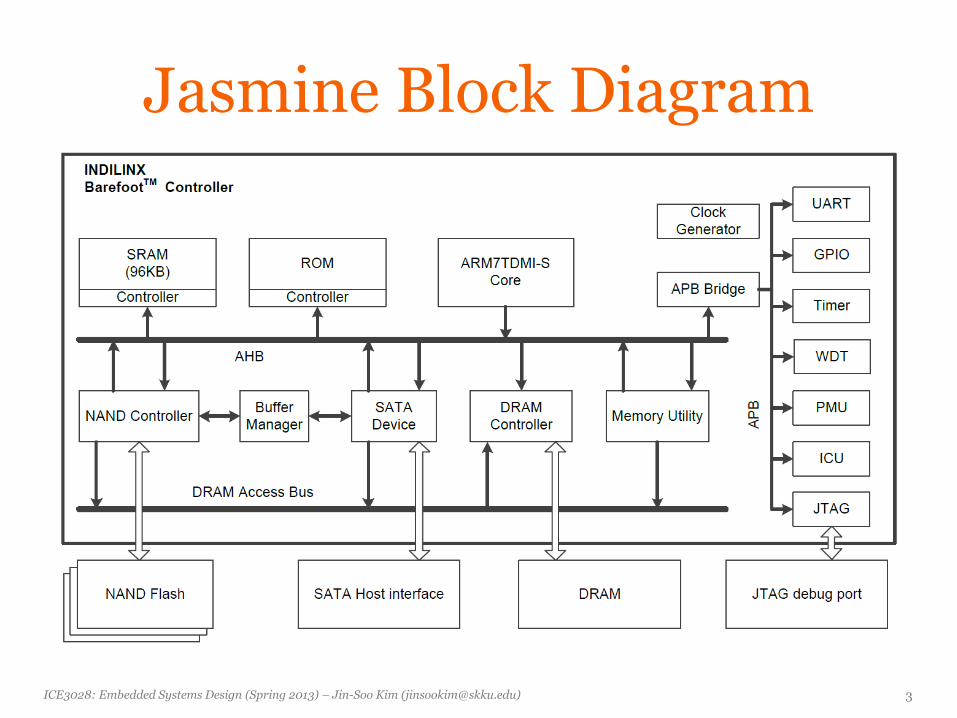
Jasmine Block Diagram
ICE3028: Embedded Systems Design (Spring 2013) – Jin-Soo Kim ([email protected]) 4
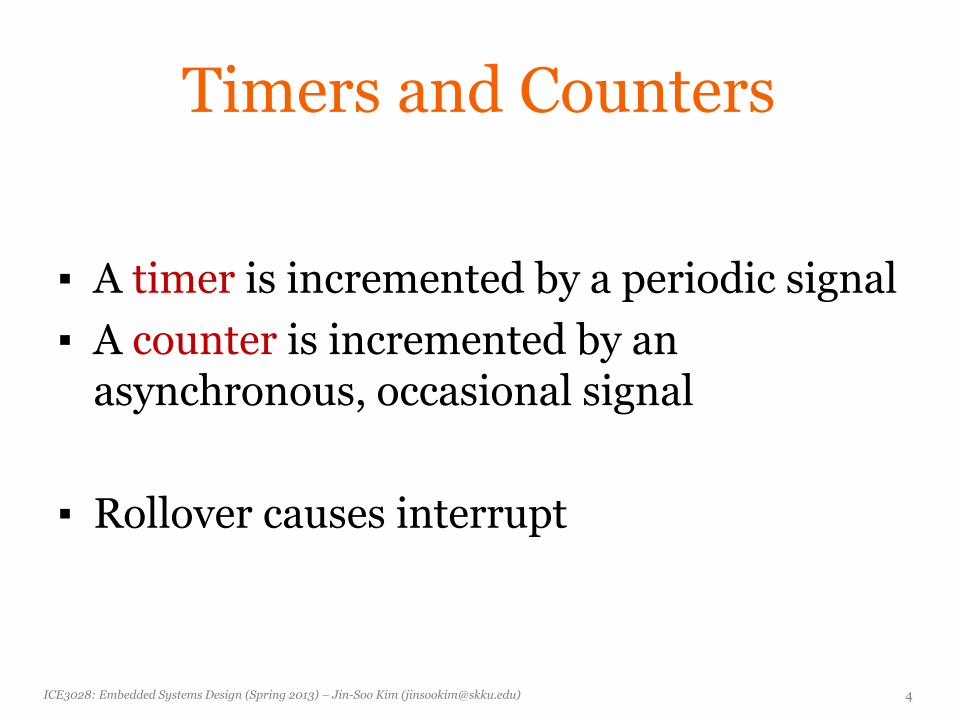
Timers and Counters
▪ A timer is incremented by a periodic signal
▪ A counter is incremented by an asynchronous, occasional signal
▪ Rollover causes interrupt
ICE3028: Embedded Systems Design (Spring 2013) – Jin-Soo Kim ([email protected]) 5
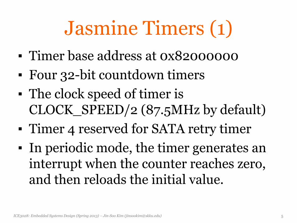
Jasmine Timers (1)
▪ Timer base address at 0x82000000
▪ Four 32-bit countdown timers
▪ The clock speed of timer is CLOCK_SPEED/2 (87.5MHz by default)
▪ Timer 4 reserved for SATA retry timer
▪ In periodic mode, the timer generates an interrupt when the counter reaches zero, and then reloads the initial value.
ICE3028: Embedded Systems Design (Spring 2013) – Jin-Soo Kim ([email protected]) 6
Jasmine Timers (2)
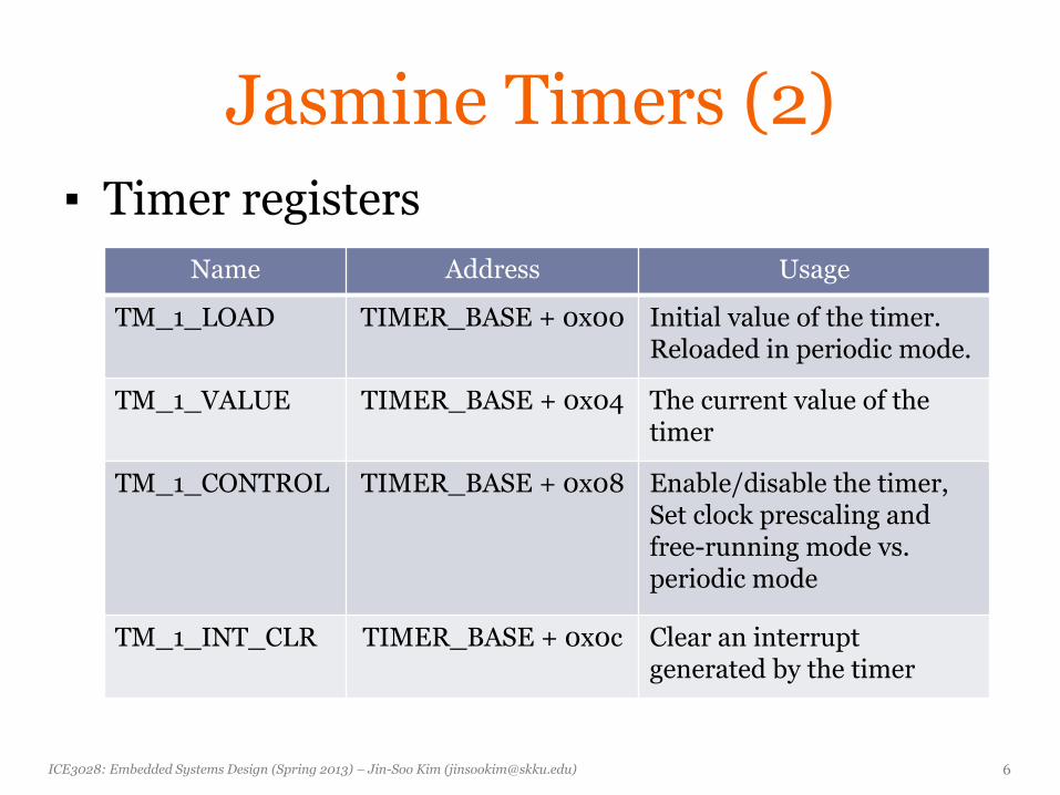
▪ Timer registers
Name Address Usage
TM_1_LOAD TIMER_BASE + 0x00 Initial value of the timer. Reloaded in periodic mode.
TM_1_VALUE TIMER_BASE + 0x04 The current value of the timer
TM_1_CONTROL TIMER_BASE + 0x08 Enable/disable the timer, Set clock prescaling and free-running mode vs. periodic mode
TM_1_INT_CLR TIMER_BASE + 0x0c Clear an interrupt generated by the timer
ICE3028: Embedded Systems Design (Spring 2013) – Jin-Soo Kim ([email protected]) 7
Jasmine Timers (3)
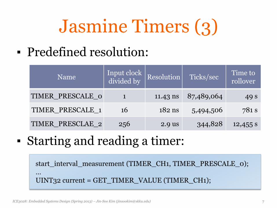
▪ Predefined resolution:
▪ Starting and reading a timer:
Name Input clock divided by
Resolution Ticks/sec Time to rollover
TIMER_PRESCALE_0 1 11.43 ns 87,489,064 49 s
TIMER_PRESCALE_1 16 182 ns 5,494,506 781 s
TIMER_PRESCLAE_2 256 2.9 us 344,828 12,455 s
start_interval_measurement (TIMER_CH1, TIMER_PRESCALE_0); … UINT32 current = GET_TIMER_VALUE (TIMER_CH1);
ICE3028: Embedded Systems Design (Spring 2013) – Jin-Soo Kim ([email protected]) 8
Jasmine Timers (4)
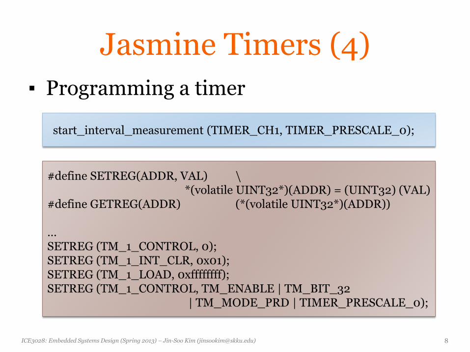
▪ Programming a timer
start_interval_measurement (TIMER_CH1, TIMER_PRESCALE_0);
#define SETREG(ADDR, VAL) \ *(volatile UINT32*)(ADDR) = (UINT32) (VAL) #define GETREG(ADDR) (*(volatile UINT32*)(ADDR)) … SETREG (TM_1_CONTROL, 0); SETREG (TM_1_INT_CLR, 0x01); SETREG (TM_1_LOAD, 0xffffffff); SETREG (TM_1_CONTROL, TM_ENABLE | TM_BIT_32 | TM_MODE_PRD | TIMER_PRESCALE_0);
ICE3028: Embedded Systems Design (Spring 2013) – Jin-Soo Kim ([email protected]) 9
Jasmine Timers (5)
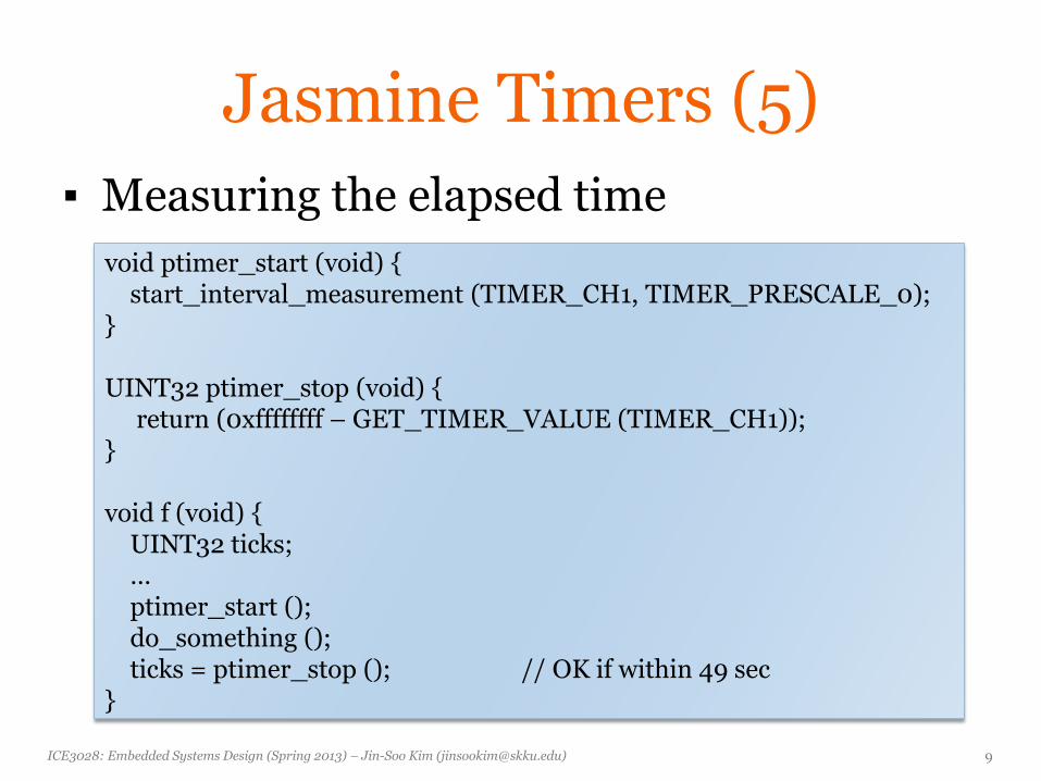
▪ Measuring the elapsed time
void ptimer_start (void) { start_interval_measurement (TIMER_CH1, TIMER_PRESCALE_0); } UINT32 ptimer_stop (void) { return (0xffffffff – GET_TIMER_VALUE (TIMER_CH1)); } void f (void) { UINT32 ticks; … ptimer_start (); do_something (); ticks = ptimer_stop (); // OK if within 49 sec }
ICE3028: Embedded Systems Design (Spring 2013) – Jin-Soo Kim ([email protected]) 10
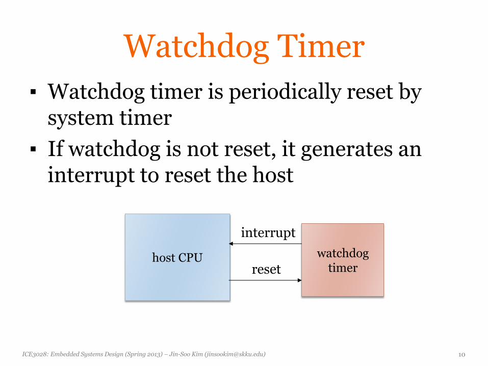
Watchdog Timer
▪ Watchdog timer is periodically reset by system timer
▪ If watchdog is not reset, it generates an interrupt to reset the host
host CPU watchdog timer
interrupt
reset
ICE3028: Embedded Systems Design (Spring 2013) – Jin-Soo Kim ([email protected]) 11
Jasmine Watchdog Timer
▪ Watchdog timer at 0x84000000
▪ 32-bit down counter with a programmable timeout interval
▪ Interrupt output generation on timeout
▪ Reset signal generation on timeout if the interrupt from the previous timeout remains unserviced by software
▪ Currently not used by Jasmine firmware
ICE3028: Embedded Systems Design (Spring 2013) – Jin-Soo Kim ([email protected]) 12
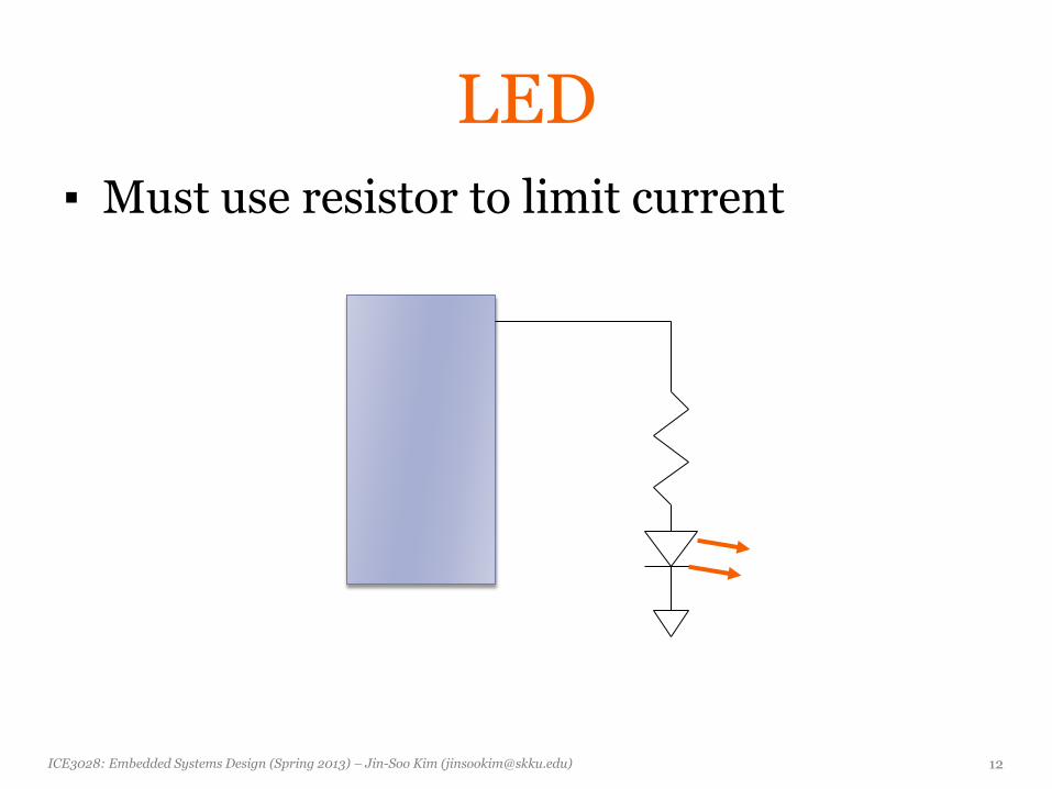
LED
▪ Must use resistor to limit current
ICE3028: Embedded Systems Design (Spring 2013) – Jin-Soo Kim ([email protected]) 13
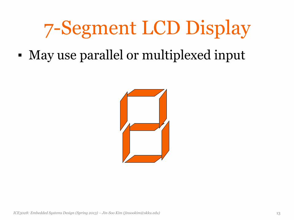
7-Segment LCD Display
▪ May use parallel or multiplexed input
ICE3028: Embedded Systems Design (Spring 2013) – Jin-Soo Kim ([email protected]) 14
GPIO
▪ General Purpose Input/Output (GPIO)
▪ A generic pin on a chip whose behavior can be controlled through software
▪ Each pin can be configured to be input or output
▪ Save the hassle of having to arrange additional circuitry to provide additional control lines
ICE3028: Embedded Systems Design (Spring 2013) – Jin-Soo Kim ([email protected]) 15
Jasmine GPIOs (1)
▪ GPIO base address at 0x83000000
▪ 7 GPIO pins (GPIO_0 ~ GPIO_6)
▪ 4 GPIO pins (GPIO_2 ~ GPIO_5) can be used to probe signals by a logic analyzer for debugging purpose
▪ GPIO_2 ~ GPIO_5 are also used for UART
▪ GPIO_0 used for factory mode jumper (J2)
▪ GPIO_6 is connected to LED (D4)
ICE3028: Embedded Systems Design (Spring 2013) – Jin-Soo Kim ([email protected]) 16
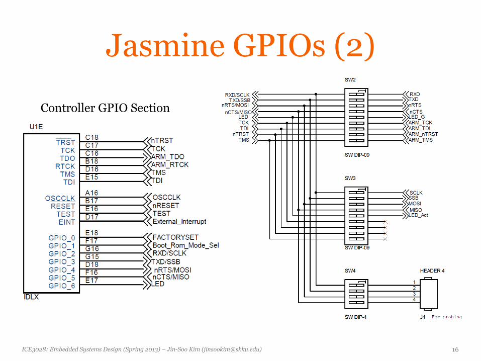
Jasmine GPIOs (2)
Controller GPIO Section
ICE3028: Embedded Systems Design (Spring 2013) – Jin-Soo Kim ([email protected]) 17
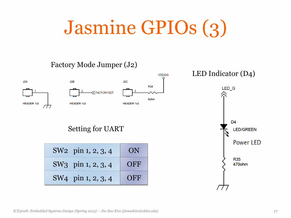
Jasmine GPIOs (3)
Factory Mode Jumper (J2)
LED Indicator (D4)
Setting for UART
SW2 pin 1, 2, 3, 4
SW3 pin 1, 2, 3, 4
SW4 pin 1, 2, 3, 4
ON
OFF
OFF
ICE3028: Embedded Systems Design (Spring 2013) – Jin-Soo Kim ([email protected]) 18
Jasmine GPIOs (4)
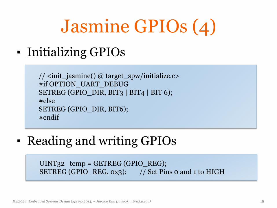
▪ Initializing GPIOs
▪ Reading and writing GPIOs
// <init_jasmine() @ target_spw/initialize.c> #if OPTION_UART_DEBUG SETREG (GPIO_DIR, BIT3 | BIT4 | BIT 6); #else SETREG (GPIO_DIR, BIT6); #endif
UINT32 temp = GETREG (GPIO_REG); SETREG (GPIO_REG, 0x3); // Set Pins 0 and 1 to HIGH
ICE3028: Embedded Systems Design (Spring 2013) – Jin-Soo Kim ([email protected]) 19
Jasmine GPIOs (5)
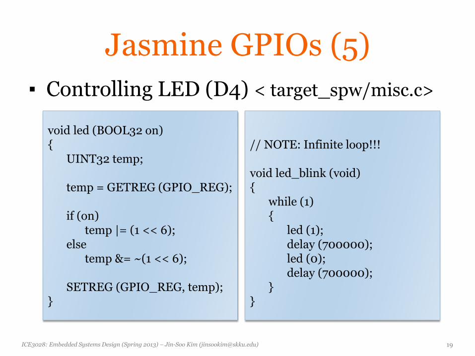
▪ Controlling LED (D4) < target_spw/misc.c>
void led (BOOL32 on) { UINT32 temp; temp = GETREG (GPIO_REG); if (on) temp |= (1 << 6); else temp &= ~(1 << 6); SETREG (GPIO_REG, temp); }
// NOTE: Infinite loop!!! void led_blink (void) { while (1) { led (1); delay (700000); led (0); delay (700000); } }
ICE3028: Embedded Systems Design (Spring 2013) – Jin-Soo Kim ([email protected]) 20
Keyboard
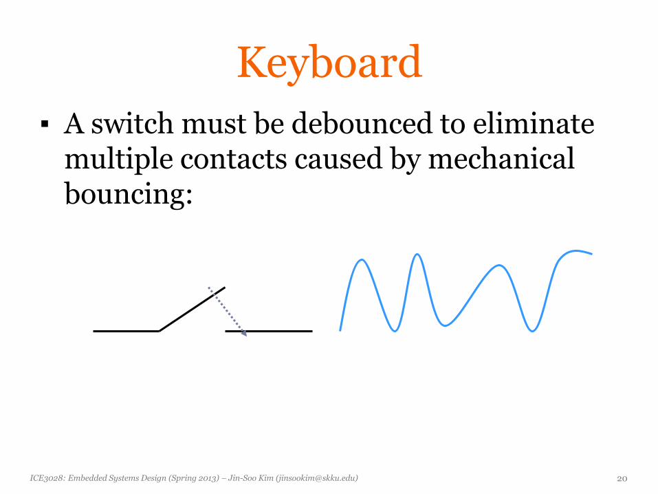
▪ A switch must be debounced to eliminate multiple contacts caused by mechanical bouncing:
ICE3028: Embedded Systems Design (Spring 2013) – Jin-Soo Kim ([email protected]) 21
Encoded Keyboard
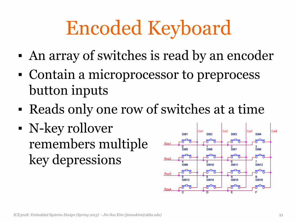
▪ An array of switches is read by an encoder
▪ Contain a microprocessor to preprocess button inputs
▪ Reads only one row of switches at a time
▪ N-key rollover remembers multiple key depressions
ICE3028: Embedded Systems Design (Spring 2013) – Jin-Soo Kim ([email protected]) 22
High-Resolution Display
▪ Liquid crystal display (LCD) is dominant form
▪ Plasma, OLED, etc.
▪ Frame buffer holds current display contents
• Written by processor
• Read by video
ICE3028: Embedded Systems Design (Spring 2013) – Jin-Soo Kim ([email protected]) 23
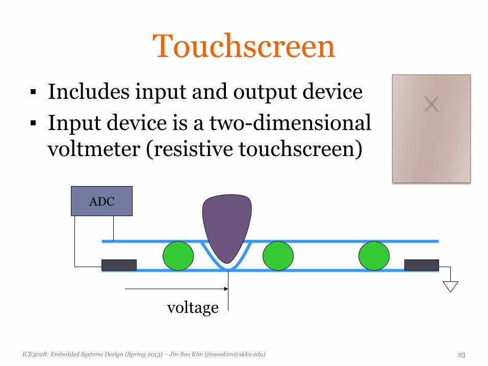
Touchscreen
▪ Includes input and output device
▪ Input device is a two-dimensional voltmeter (resistive touchscreen)
ADC
voltage

Development & Debugging
ICE3028: Embedded Systems Design (Spring 2013) – Jin-Soo Kim ([email protected]) 25
Debugging Challenges
▪ Target system may be hard to observe
▪ Target may be hard to control
▪ May be hard to generate realistic inputs
▪ Setup sequence may be complex
ICE3028: Embedded Systems Design (Spring 2013) – Jin-Soo Kim ([email protected]) 26
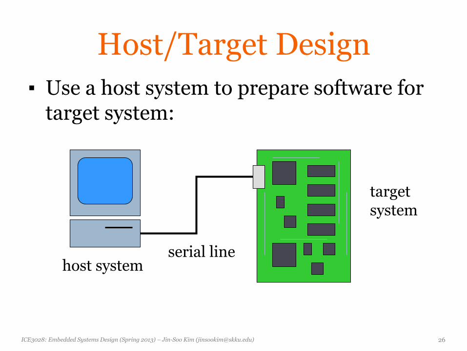
Host/Target Design
▪ Use a host system to prepare software for target system:
target system
host system serial line
ICE3028: Embedded Systems Design (Spring 2013) – Jin-Soo Kim ([email protected]) 27
Host-based Tools
▪ Cross compiler
• Compiles code on host for target system
▪ Cross debugger (or remote debugger)
• Displays target state, allows target system to be controlled
ICE3028: Embedded Systems Design (Spring 2013) – Jin-Soo Kim ([email protected]) 28
Software Debuggers
▪ A monitor program residing on the target provides basic debugger functions
▪ Debugger should have a minimal footprint in memory
▪ User program must be careful not to destroy debugger program
▪ The debugger should be able to recover from some damage caused by user code
ICE3028: Embedded Systems Design (Spring 2013) – Jin-Soo Kim ([email protected]) 29
Breakpoints
▪ A breakpoint allows the user to stop execution, examine system state, and change state.
▪ Replace the breakpointed instruction with a subroutine call to the monitor program
ICE3028: Embedded Systems Design (Spring 2013) – Jin-Soo Kim ([email protected]) 30
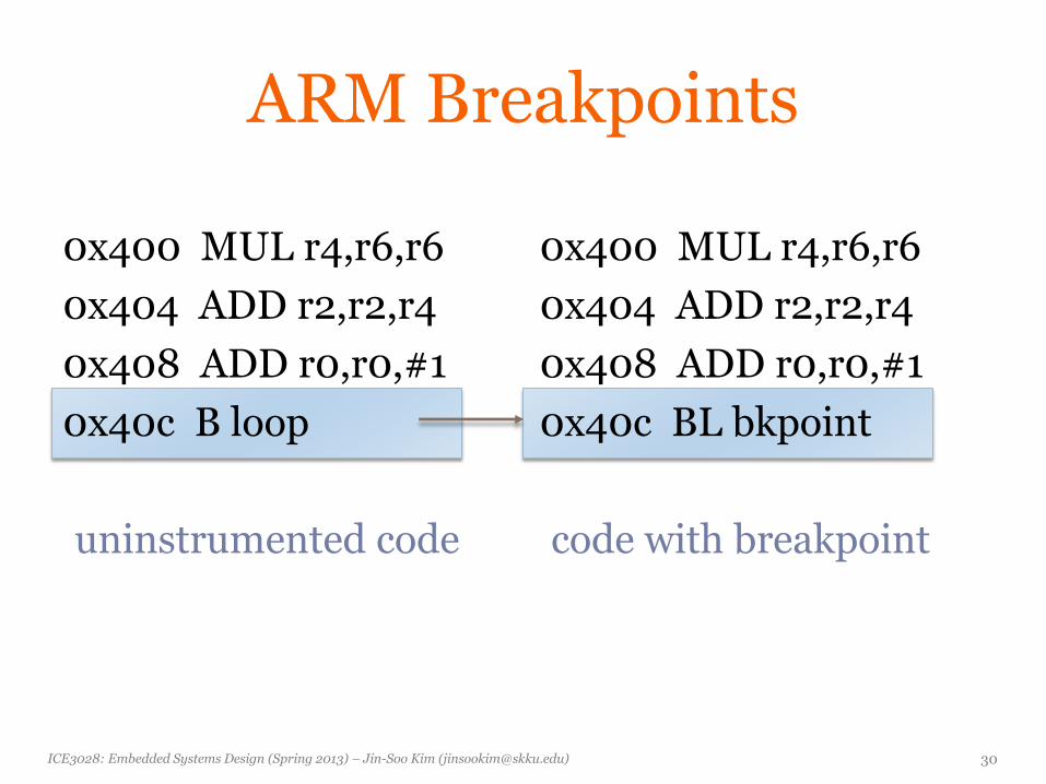
ARM Breakpoints
0x400 MUL r4,r6,r6
0x404 ADD r2,r2,r4
0x408 ADD r0,r0,#1
0x40c B loop
uninstrumented code
0x400 MUL r4,r6,r6
0x404 ADD r2,r2,r4
0x408 ADD r0,r0,#1
0x40c BL bkpoint
code with breakpoint
ICE3028: Embedded Systems Design (Spring 2013) – Jin-Soo Kim ([email protected]) 31
Breakpoint Handler
▪ Save registers
▪ Allow user to examine machine
▪ Before returning, restore system state
• Safest way to execute the instruction is to replace it and execute in place
• Put another breakpoint after the replaced breakpoint to allow restoring the original breakpoint
ICE3028: Embedded Systems Design (Spring 2013) – Jin-Soo Kim ([email protected]) 32
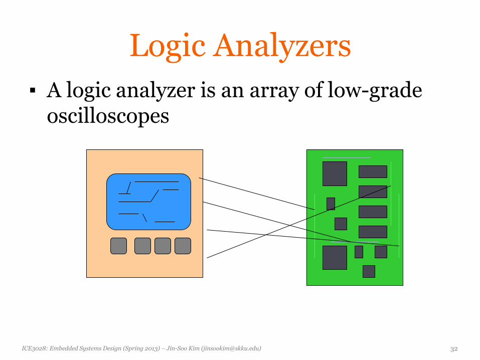
Logic Analyzers
▪ A logic analyzer is an array of low-grade oscilloscopes
ICE3028: Embedded Systems Design (Spring 2013) – Jin-Soo Kim ([email protected]) 33
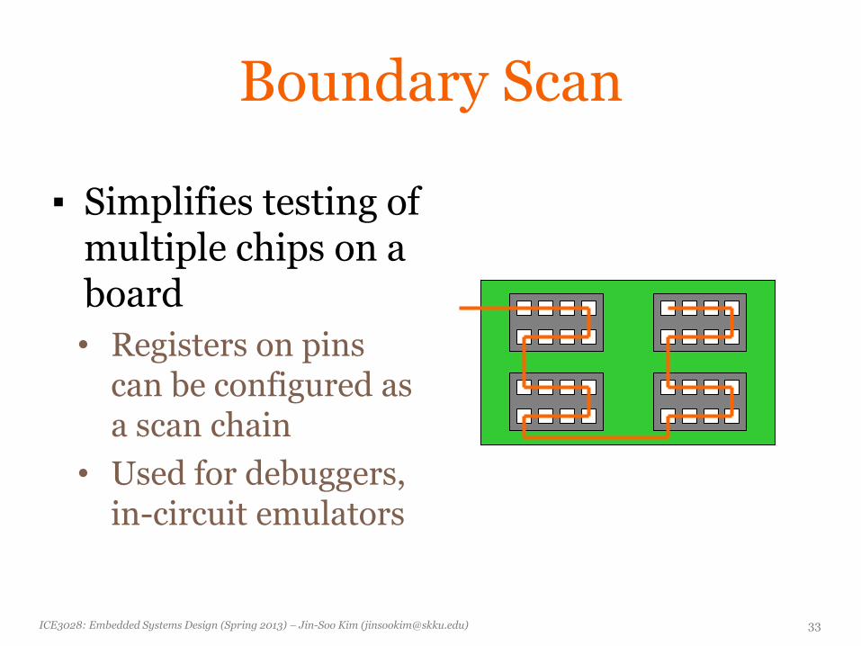
Boundary Scan
▪ Simplifies testing of multiple chips on a board
• Registers on pins can be configured as a scan chain
• Used for debuggers, in-circuit emulators
ICE3028: Embedded Systems Design (Spring 2013) – Jin-Soo Kim ([email protected]) 34
In-Circuit Emulators
▪ A microprocessor in-circuit emulator is a specially-instrumented microprocessor
▪ JTAG-based hardware debuggers use on-chip debugging hardware with standard production chips
▪ Allows you to stop execution, examine CPU state, modify registers
ICE3028: Embedded Systems Design (Spring 2013) – Jin-Soo Kim ([email protected]) 35
How to Exercise Code
▪ Run on host system
▪ Run on target system
▪ Run in instruction-level simulator
▪ Run on cycle-accurate simulator
▪ Run in hardware/software co-simulation environment