Embed Size (px)
Citation preview

NEUTRON RADIOGRAPHY WITH CYCLOTRON
E. Hiraoka Radiation Center of Osaka Prefecture. Sakai. Osaka 593. Japan
The technique using thermal neutrons was demanded because of its inspection ability to show hydrogeneous material such as plastics, water, explosives or composite materials and irradiated nuclear fuel capsules. This paper describes some experimental results and applications in neutron radiography by the use of several small cyclotrons producing neutrons by Be(p,n) reaction.
Introduction
In recent years considerable attention has been paid to neutron radiography. The technique using thermal neutrons was demanded because of its inspection ability to show hydrogeneous material such as plastic, water, explosives or composite materials and irradiated nuclear fuel capsules. The technique is similar to radiography with X or y rays. The remarkable merits of neutron radiography comes from large differences in the absorption coefficient of element, compared with X or y rays. The absorption coefficient varies randomly as a function of atomic number.
Radiography with thermal neutrons has been mainly developed by the use of high intensity neutron flux produced by nuclear reactors. Presently, it is much necessary to extend its applicability to various fields. It is also important to install neutron radiography facilities, which are more convenient and economical than reactor based system.
To satisfy the conditions mentioned above, accelerator based systems had been proposed for a long time and investigated at a laboratory level by using Van de Graaff accelerators in the energy range of a few MeV to produce neutrons by the 9Be(d, n)10B reaction.
The author and his coworkers had started the study on neutron radiography in 1969. At first, we used 14-MeV neutrons from D-T reaction on a I-MeV Van de Graaff accelerator and photo-neutrons from y-n reaction on an 18-MeV linear electron accelerator. 2) Then we had continued the study with the Kyoto University Reactor (KUR) since 1975.
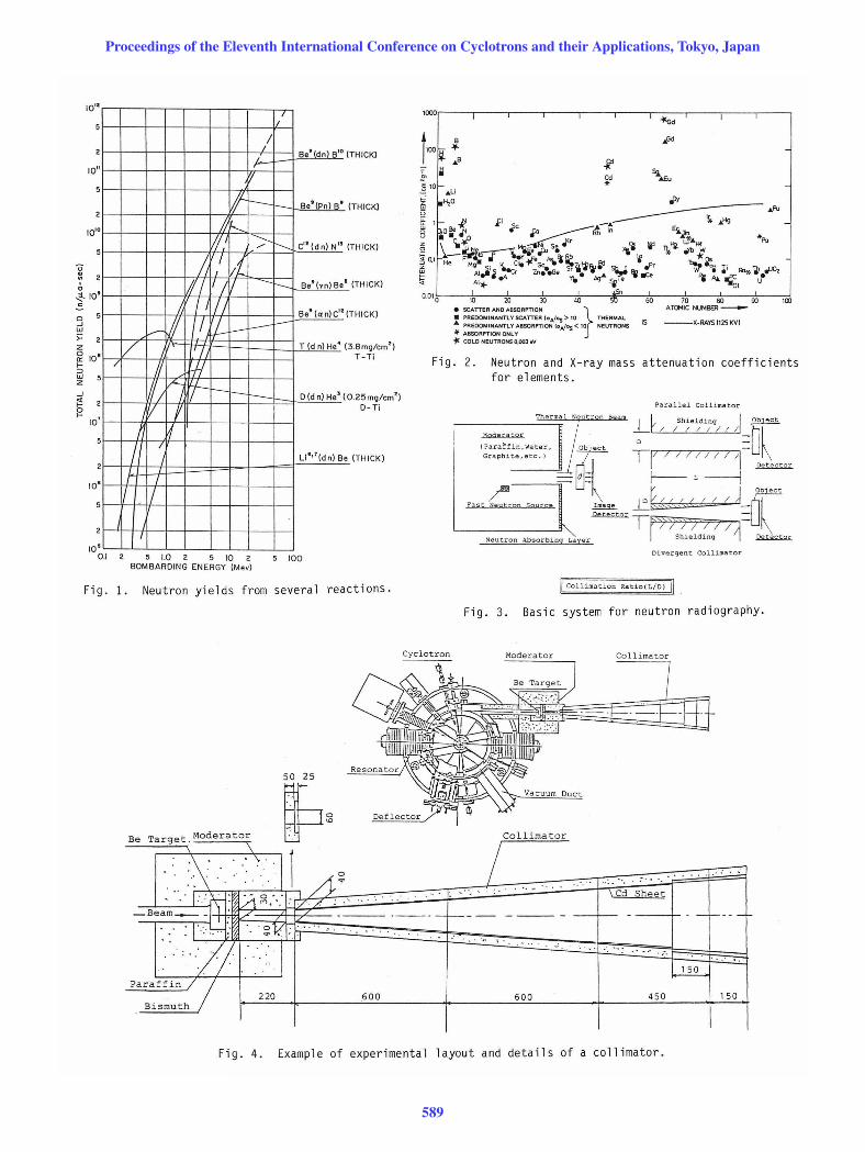
In the late 1970s, we were consulted by the National Space Development Agency of Japan (NASDA) on the application of neutron radiography. On the basis of our experience, we examined various methods and conditions to find best ones. We have taken note of the following fact: The neutron flux generated by the (d,n) and (p,n) reactions on Be increases with the accelerator energy to the second or third power3- 7) (see Fig. 1). The (p,n) reaction on Be has been considered more useful, because the neutrons from this reaction have lower energies4,5) and therefore higher efficiency for thermalization.
Luckily, small cyclotrons recently developed for medical uses produce protons of higher energies than conventional accelerators for application purposes, and are convenient to operate. Therefore, we have concluded to use such cyclotrons for neutron radiography, and constructed the system for practical applications. The greatest advantage of the accelerator system is that the generation of neutrons stops when the accelerator is switched off. Other advantages of the system consist in compactness and
easiness of operation and maintenance. We report here mainly the merits of the neutron
radiography system by the use of the cyclotron and some applications of this system.
Principle of Radiographic Imaging
In neutron radiography, the penetrating nature of neutron radiation is used to obtain information about the internal structure of an object. Figure 2 shows how the attenuation coefficient of element change for thermal neutrons. 8) A high neutron attenuation means high contrast for small thicknesses of material. As the comparison, the attenuation coefficient of X-ray is also shown. A basic system of neutron radiography is shown in Fig. 3. It consists of a neutron source, a moderator to thermalize neutrons, a beam collimator and an imaging detector.
Imaging is usually performed using a fine grain, single coated X-ray film in a cassette with a Gd foil converter contacted directly to the film. The incident thermal neutrons captured by the Gd foil produce localized ionizing radiations (internal conversion electrons) which expose the film.
Experimental and Results with Cyclotrons
Since 1980, we have carried out the study and testing of neutron radiography with cyclotrons. The cyclotrons used in the experiment are those of Japan Steel Works, Ltd. (Baby Cyclotron BC 168), Cyclotron Radio-Isotope Center of Tohoku University (Sumitomo and CGR-MeV 680) and Toyo Works of Sumitomo Heavy Industries in Ehime (Sub-Compact Cyclotron 480).
An example of experimental layout is shown in Fig. 4. This is an earlier assembly of neutron radiography attached to a cyclotron. The accelerated protons impinge upon a beryllium target and produce copious quantity of fast neutrons. These fast neutrons are slowed down to the thermal energy region with a polyethylene moderator surrounding the target. A fraction of the thermalized neutrons are extracted from the target area by a collimator constructed with polyethylene boards. A bismuth filter about 20 mm in thickness is inserted at the inlet of the collimator to eliminate y rays.
Table 1 shows the summary of the experiment for the neutron radiography system of the accelerators and the Kyoto University Research Reactor (KUR 5MW). The thermal neutron flux was measured by activation method with gold foils and the y-ray intensity was measured by TLD elements.
On the basis of the experiences obtained from the fundamental experiment, the cyclotron based neutron radiography facilities have been installed at Japan Steel Works, Ltd. in Hokkaido and at Toyo Works of Sumitomo Heavy Industries, Ltd. in Ehime Prefecture.
Both the facilities have dual collimator system for practical use. The former uses two collimators arranged in the directions of 0 and 90 degrees, and the latter in the vertical and horizontal directions with respect to the beam line. Figure 5 shows the facility
Proceedings of the Eleventh International Conference on Cyclotrons and their Applications, Tokyo, Japan
587

of Sumitomo Heavy Industries Ltd. Figure 6 shows the curves of typical density
exposure characteristic on the KUR and the Cyclotron for various films with NE426, 905 (scintillation screen) and Gd converter. Here the exposure is expressed by total thermal neutron flux. The best resolution is obtained by the combination of the Gd converter and Kodak SR. In this case, the exposure time will be about 1000 sec at film density of 2.5 in a beam of 106 n/cm2·sec (see Table 1).
Recently, the real time X-ray radiography has been established for the medical field, and has been applied for some industrial fields assisted by advance of digital image processing and electronics. We have tried to perform the real time neutron imaging system with the cyclotron to observe the dynamic behavior of fluids and plastics in hydraulic components, plastic injectors and so on. The arrangement of the system is shown in Fig. 7. The neutrons that passed the object arrive on a fluorescent converter screen composed of the granular mixture of LiF and ZnS(Ag). The photo-image is observed by a TV camera using an RCA silicon intensifier target (SIT) tube. The camera provides automatic level adjustment. The video-signal obtained from the camera can be stored in a video recorder or be reconstructed by a set of digital image processors. At present, the resolution of 1.0 line pair/mm is obtained at the object-field size of 250 x 200 mm2.
Application of Neutron Radiography
Figure 8 shows the neutron radiographic images of some detonators. The pictures are the first trial ones for the inspection requested from NASDA of explosive devices. The detonators are the dummies filled with sugar instead of explosive compound. As seen from the images, some of these have the defects caused by small pieces of aluminum embedded in the fillings. These defects are undetectable by y- or X-ray radiography.
Other images on the picture are the ASTM* Indicators to check neutron beam quality and radiographic sensitivity. The inspection of the actual explosive devices for H-1 launch vehicles have been carried out constantly by this method.
Figures 9 and 10 are the examples of X-ray and neutron radiographic comparison (XRT and NRT) for ancient arts. The samples tested are as follows:
Sample (a)
An unearthed Buddhist sutras in a bronze case (10c. A.D.) (Fig. 9): dimensions of the case; diameter =12.1 cm, height = 29.5 cm, thickness of the wall and the base = 1-2 mm. The bronze sutra case and the Buddhist sutras contained were excavated from a sutra mound. The sutras made of Japanese paper had deteriorated under the earth during about 1000 years, and had changed into a gray lump similar in appearance to excrement. After excavation, they were reinforced by impregnation with acrylic resin.
Sample (b)
A Tibetan unglazed Buddhist statue cushioned with cloth in a copper box with a window (Fig. 10): dimensions of the box; height = 12.7 cm, width = 10.5 cm, depth = 4.8 cm.
The results observed for these samples are as follows:
Sample (a)
* The American Society for Testing and Materials
XRT: Part of the sutras are visible but unclear. It cannot be recognized what they are. The corrosion of the sutra case and its tinkered part are very clear.
NRT: The sutras in the bronze case are imaged most clearly as if the bronze case were transparent. Even rolled pieces of paper of sutras can be seen.
Sample (b)
XRT: The patterns of the copper box are plainly seen. Buddhist statue can be recognized vaguely. The cloth is not imaged.
NRT: The outline of the bronze case is clear, and the thickness of the copper plate can be recognized. The Buddhist statue is imaged only faintly, but folds of cloth is very clear.
Conclusion
This paper has outlined the neutron radiography with cyclotrons. From the experimental results, we can conclude that the characteristics of the neutron radiography system with the cyclotron is very useful and is a match for that of reactor.
The author wish to acknowledge the joint efforts8- 15 ) of the members from the Japan Steel Works Ltd., Sumitomo Heavy Industries Ltd., Nissan Motors Co. Ltd., Tesko Corporation, the Kyoto University Reactor Institute, Gangoji Institute for Research of Cultural Property, Kobe University and others. This work was supported in part by a Grant-in-Aid from the Ministry of Science and Technology Agency. It was also performed partly by a grant-in-Aid from the Ministry of Education, Science and Culture.
References
1) F. R. Swanson, Practical Application of Neutron Radiography and Gauglng (Amerlcan Soclety of Testlng Materlals, 1976).
2) E. Hiraoka, Neutron Radiography, Proc. 1st World Conf. San diego, Dec. 1981 (D. Reldel, U. S. A. 1982) p. Ill.
3) E. A. Burril, Neutron Production and Protection (High Voltage Englneerlng Corporatlon) p. 28.
4) M. A. Lane, Nucl. Instrum. & Methods 143, 331 (1977). -
5) F. T. Kuchnir, Amer. Inst. Phys. Conf. Proc. no. 9 (1972).
6) J. A. Stokes, IEEEE Trans. Nucl. Sci. NS-30, No.2 (1983).
7) M. R. Hawkesworth, At. Energ. Rev. ~, No.2 (1977) .
8) H. Berger, Neutron Radiography (Elsevier, 1965) p. 5.
9) K. Yamawaki et al., Neutron Radiography, Proc. 2nd World Conf., Paris, June 1986 (In press).
10) S. Tazawa et al., lbld. 11) E. Hiraoka et al., ibid. 12) R. Taniguchi et al., ibid. 13) A. Ono et al., ibid. 14) F. Masuzawa et al., ibid. 15) Y. Fukushima et al., ibid.
Proceedings of the Eleventh International Conference on Cyclotrons and their Applications, Tokyo, Japan
588
10 .. 5
2
10 " 5
2
10 '0
5
~ 2 , o ~IO .5
,
o ..J W
>= Z
5
2
~ 10 I
, ::> w z 5
..J 2
, ~ 10
5
2
10 .
10 . 0.1
/
/ ~
W' t--
J; ~ W >
~ 7 Iii rn 17 III
/, / I III I.-W T! rl l- I--------
V I II I rJ-I
ffl r- rt-f - r--t--(j f
~ ;/ I
r 7 I' , II
I
5 1.0 2 5 10 2 BOMBARDING ENERGY (Mev)
II
-
--------
r--
I-
Se'(dn) R'o ( THICK)
Se' (Pn) S' (THICK)
C"(dn) N" ( THICK)
Be'(,n) Be' (THICK)
Be'(an)C"( THICK)
T(dn)He'(
O(d n) He' (
3.8mg/cm') T-Ti
0 .25mg/cm') O-Ti
U"'(dn) Se (THICK)
5 100
'~Ir---~r----.-----r----,-----~----r---~----~----~--~ 1«;d
• SCATTERANOA8SORPTION } % PREDOMINANT1. Y SCATTER lOA/Os > 10 THERMAL
PREDOMINANTLY A8SORPTION (o ... 'Os< 10 NEUTRONS *' ABSORPTION ONLY ~ COLO NEUTRONS 0.003.v
--X·RAYSI12SKVI
Fig . 2. Neutron and X-ray mass attenuation coefficients for elements.
Parallel Collima tor
Thermall Neutron Beam Lt / / h;el/;;n"/ I ) oret
(~;:;!:;:~:;:~~. Jeet TI/ / I / / / I l 1= ~ -----i;- ~=l f--- L ------1 Detector
'ast Coon So"rce ~:;:;tQ; ll<-, ,< ; / / J _oret TF1 ) ';) // / A "'-
Neutron Absorbing Layer I · Shl.eldinq / I Dete ct:or
Diverg ent. Coll imato r
Fig. 1. Neutron yields from several reactions. II Collimation Ratio(L/O) II
Fig. 3. Basic system for neutron radiography.
Cyclotron
50 25
Bo ,"",0 .. '0'"""'0< ~" 0o '"'m",o<
. '\ . ', 11 ~ /... ... ' . . .
". 1 ~ .~.- o~-, ~~~~~~~E~~sheeI~ . . , /\"", ', '77 _Beam_ -I : / --t--- ' -f----->7/ ~I '. '. . ... Paraffin 77
220 Bismuth 600 450 150 600
Fig, 4. Example of experimental layout and details of a collimator.
Proceedings of the Eleventh International Conference on Cyclotrons and their Applications, Tokyo, Japan
589
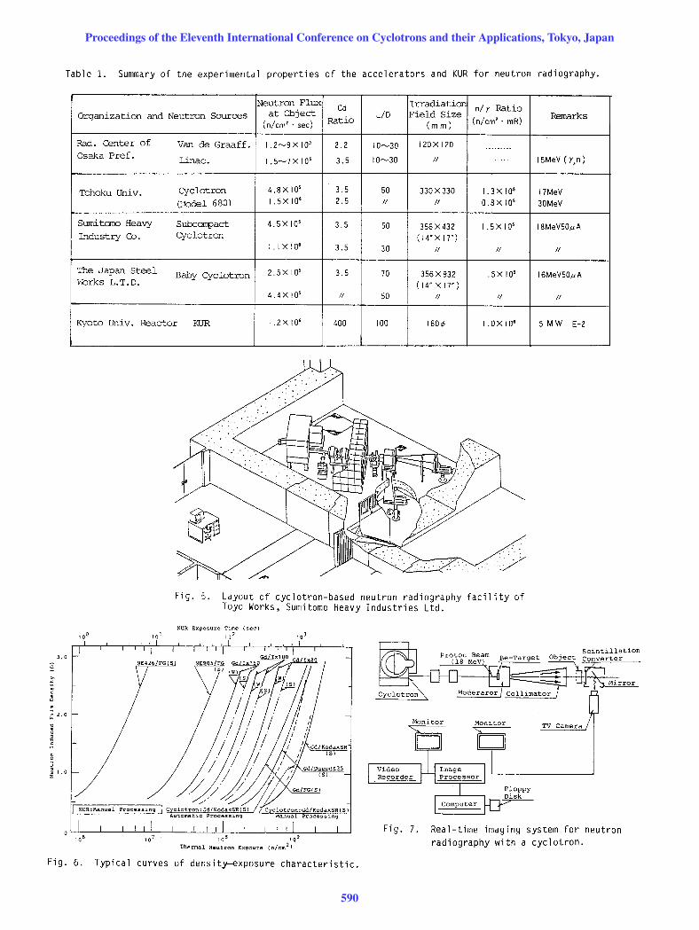
Table 1. Summary of the experimental properties of the accelerators and KUR for neutron radiography.
3.0
Neutron Flux Cd Irradiation
n/y Ratio Organization and Neutron Sources at Object
Ratio LiD Field Size (n/em'· mR)
Remarks (n/em' . see) (mm)
Rad. Center of Van de Graaff. I .2~9X 10' 2.2 10~30 120 x 120 ....... _-Osaka Pref. Linac. I.S~7X 10' 3.S 10~30 II --------- ISMeV (r,n)
Tohoku Univ. Cyclotron 4.SX 10' 3.S SO 330 x330 1.3x 10' 17MeV
(r1odel 680) I.SX 10' 2.S II II O.SX 10' 30MeV
Sumi. tano Heavy Subcorrpact 4.SX 10' 3.5 SO 3S6 X 432 I .SX 10' ISMeVSO,uA Industry Co. Cyclotron (14'X 17')
1.1 X 10' 3.S 30 II II II
The Japan Steel Baby Cyclotron 2 .SX 10' 3.S 70 3S6 X 932 1.5X 10' 16MeVSO,uA "Iorks L.T.D. (14" X 17')
4. 4X la' II SO II II II
Kyoto Univ. Reactor KUR I .2X 10' 400 100 160¢ I .OX 10' SMW E-2
10 0
'./
Fig. 5. Layout of cyclotron-based neutron radiography facility of Toyo Works, Sumitomo Heavy Industries Ltd.
KUR Exposure Time (sec)
10'
TV Camera
Scintillation Converter
ffi;rror
Thermal Neutron Expoure
Fig. 7. Real-time imaging system for neutron radiography with a cyclotron.
Fig. 6. Typical curves of density-exposure characteristic.
Proceedings of the Eleventh International Conference on Cyclotrons and their Applications, Tokyo, Japan
590

•
• • • I I I
1t I
Fig . 8. Neutron radiographic images of some detonators.
Photograph XRT NRT
Fig. 9. Photograph and radiographs of unearthed Buddhist sutras in the bronze case .
Proceedings of the Eleventh International Conference on Cyclotrons and their Applications, Tokyo, Japan
591

Photograph XRT NRT
Fig. 10 . Photograph and radiographs of Tibetan unglazed Buddhist statue.
Proceedings of the Eleventh International Conference on Cyclotrons and their Applications, Tokyo, Japan
592