Embed Size (px)
Citation preview

217
8» CO
Proceedings of National Seminar on 'Concrete Design and Construction Practices'Indian Concrete Institute and MA/*? Engineering College, Allahabad, Dec. 21-23, 1989.
INVITED LECTURE
CONSTRUCTION TECHNIOUES FOR FERROCEMENT WATER STORAGE TANKS.
P.C. SHARMAScientist & Project Leader,Drinking Water Mission Project.Structural Engineering Research Centre Ghaziabad, U.P.
" ABSTRACT
Ferrocement water storage tanks have been found to be safe,
economicaland easy to construct and maintain even in very difficult
remote areas. Various site and problem specific construction
techniques have been developed by various R&D groups for making
ferrocemnt tanks of small and medium capacities. The paper presents
few of these techniques. Three casting methods developed at SERC,
Ghaziabad in India have become very popular among field
engineers/contractors and are being used on large scale in actual
field projects and the structures constructed are performing very
well.
INTRODUCTION
The importance of storing drinking water in safe and
hygienic structures is now being realised in a much better way in
many countries. In India, the programme of providing safe drinking
water to all rural citizens by the year 1991, has been taken up by
the Department of Rural Development, Government of India under a
National Technology Mission on Drinking Water. Besides finding and
development of other water sources, it has been felt necessary to
^ collect effectively and store the rain water at an appropriate:] season and utilise it judiciously so that the requirement of water,,
' Vi for drinking purpose, is met with in a sustained manner for a
reasonable period. Quite large area of the country, such as North-
-1-2S

Eastern hills, coastal belt and islands, plain areas of central and
North India, normally get sufficient rain fall. The Mission has
accorded a very high priority for taking up rain water harvesting
schemes and ferrocement water storage tanks. In the process of
collection and storage of rain water, the role of a safe and
hygienic water storage reservoir/tank is very important. It holds
the collected wateT in a hygienic environment for preventing its
getting contaminated during storage. It also, forms a major
component expenditure-wise for any rain water harvesting system.
Several types of reservoirs/tanks are in use for storing of
water in various parts of the world. Tanks of various shapes are
being adopted. Some of the popular shapes are, rectangular,
cylindrical and spherical. Tanks are constructed using (1) brick/
stone/R.C.C. block masonary (2) reinforced cement concrete (3)
steel/G.I. sheets (4) ferrocement (5) bamboo reinforced concrete
(6) fibre reinforced plastic (7) composite construction using brick
and R.C.C./ferrocement, and (8) high density pothythelene.
Detailed studies carried out at various research organiza-
tions, experiences in field and long term behaviour studies on
ferrocement tanks have established that F.C. tanks have an edge
over the other alternatives. Ferrocement is a construction material
which is ideally suited for construction of water storage tanks due
to its higher resistance against cracking, impact, shock and
moisture migration. It can be moulded in any shape and does not
require formwork. Structures made with ferrocement are thinner
than R.C.C., lighter in weight hence need lighter supporting
structure. Ferrocement construction does not require any heavy
plant or machinery or highly skilled labour as needed for fabrica-
tion of steel or R.C.C. structures. These do not get damaged with
normal impact, shock loads or fire as in the case of masonary and
plastic tanks. These are economical in comparison with RCC, masonary,
steel and plastic (H.D.P.) tanks. With its advantages and easy
availability of its constituent materials in most of the places,
feriocement is an ideal construction material for water storage
- 0-66 - '

tanks in rural and urban areas for large type of water supply and
minor irrigation schemes. Tanks can be installed in underground,
part underground and part aboveground and overhead conditions.
In India, the Structural Engineering Research
Centre, Ghaziabad has been a pioneer institution in the field of
Research & Development on ferrocement. The Centre is one of the
main institutions working on rain water harvesting system for the
National Technology Mission in India. The Centre has done
considerable work on development of ferrocement structures and
many techniques, for production of ferrocement applications such as
water tanks, storage bins, septic tanks, roofing units, wall panels
irrigation channels, manhole covers, leak proofing treatment for
masonary and RCC structures, biogas digesters, check dams have been
developed.
1. Traditional Construction Technique (Skeletal Cage System) :
This technique is used in most parts of the world and involve steps
of (a) fabrication of a skeletal cage representing the true si2e
and shape of the tank with M.S. bars, (b) fixing of a minimum of
two layers of wire meshes over skeletal cage (c) plastering and
finishing with trowel and wooden float (d) curing, & (e) painting.
Though, this is a simple mouldless construction technique,
needing no infrastructure, but has the disadvantage of difficulty
in control of uniformity of thickness. Getting thickness below 20mm
is difficult even in case of smaller tanks. Fig. 1 to 4 show
various stages of a 10,000 litre F.C. tank construction at Jodhpur.
2. Iaproved Techniques for Casting of Cylindrical F.C. Wall
Units for Water Tanks
2(a) Seal-Mechanised Process for Producing Cylindrical
Ferrocement Units - (Indian Patent No.145250) :
In this semi-mechanised casting process developed at SERC,
Ghaziabad, a continuous winding of wire mesh from a wire mesh roll
on to a cylindrical mould and simultaneous application of high
- 0-67 -

strength cement sand mortar on the wire mesh as and when it is
wound on the mould is achieved. This enables to have high degree of
compaction of mortar and a very good control over the thickness of
the cast unit. Process is labour intensive and does not require
power or expensive machinery. Diagramatic representation(elevation)
of the casting process equipment is presented in Fig. 5. The
process of casting consists of the following steps (refer fig.5) :
1. Wire mesh roll for the reinforcement of the wall unit is
mounted on the Spindle 'A* and the wire mesh roll, for
collar portion reinforcement of unit, is mounted on Spindle
'B1. Spindles carrying the reinforcing meshes are fixed over
a 'A frame' fixed vertical over stand 1.
2. Mould (made of quickly openable three to six segments)
bolted together for casting the cylindrical wall unit is
mounted on stand 2. Joint battens are provided in between
two mould segments.
3. . End of the mesh rolls wrapped over spindles are passed
through guide rollers A&B as shown in Fig. 5 and initially
tied to the cylindrical mould by passing a twin twisted
steel wire through holes provided in one of the joint
battens.
4. Cylindrical mould is rotated in the forward direction as
shown by arrow in Fig.5, so that the mesh gets wound on the
mould and moves along with the mould. When a sufficient
portion of the wire mesh is wound on the mould, the rotation
of the mould is arrested by inserting a 40 mm dia M.S. pipe
through the mould and over connecting angle CA. 12 x 3 mm
M.S. flat pieces are inserted between the mould surface and
the mesh and high strength cement sand mortar (1:2) added
with poresealing and plasticizing compounds, is applied on
the portion of the wire mesh wound on the mould. After the
application of mortar, the mould is rotated further so that
the next portion of .wire mesh gets wound on the mould and
mortar is applied on the wire mesh in continuation of the
portion on which mortar was already applied. Thus, the
- 0-68 -

process goes on continuously and the application of cement
mortar is done layer by layer on the mesh till the required
number of wire mesh layers are wound on the mould and the
required thickness of the mortar in wall unit is obtained.
5. The last layer of wire mesh is given an extra overlap length
and the wire mesh is tied to the mesh below (already
plastered) at close interval. The mesh is then cut and the
surface is finished with cement mortar maintaining proper
cover to the outer most reinforcement layer.
6. The unit is demoulded after 24 hours but the mould could be
shifted from the stand soon after the casting is over.
7. The wall unit is given a finishing coat with 1:1-5 cement,
sand mortar on the inside surface and is cured for at least
7 days with water before using it for assembling of tanks.
The process described is being used for producing wall units
for water storage tanks upto 5,000 litre capacity which has a
thickness of only 18 mm. The same wall units are also used for
assembling of septic tanks, grain or oilseed storage bins, biogas
digesters, garbage bins etc. The base of the tank is precast in
RCC. The dome shaped roof and lid are cast using ferrocement.
Figure 6 shows various precast components for a F.C. tank of 1250
lit. capacity, produced using SERC process. Low cost masonary
moulds (constructed by plastering soil deposited in shape) have
been developed for casting of roof and lid. Tanks casted with this
technique are light in weight but strong in strength. This process
has been released through N.R.D.C. to more than 55 entrepreneurs
for commercial production of cylindrical ferrocement structures.
2 (b) SERC Segaental Units : Casting and Jointing Method
(Indian Patent No.175250)
During mass production trials and transportation tests
conducted by SERC on ferrocement tanks, bins and septic tanks, it
was observed that cylindrical units having larger diameter above
_1.5m need special care and effort during transportation and
- 0-69 -

handling. For solving this problem, a system of using vertical
F.C. segmentalunits for assembling of cylindrical walls for tanks
etc. was developed at SERC. Using this technology, units needed for
construction of cylindrical structures can be easily cast,
transported, erected and joined. The shape of these precast units
are cast in the form of a segment of a cylinder. The
circumferential surface of cylinder is divided into 4,6,8 or even
more number of parts. These segments of sthe cylinder are cast as
individual precast units with meshes and cross reinforcement
wires/bars projecting on both sides of the unit. This projected
reinforcement is used for jointing of a segment with the adjacent
segments on both sides. The projection of reinforcement is kept in
such a way that laps transfer the full hoof stress coming in the
unit on full load. The units are transferred and placed in jointing
position. Mesh joints are fixed and mortar is applied. These
individual units have been termed as segmental shell units. A
system of making and using low cost masonary moulds has been
developed and used for casting of these precast segmental units.
On special requirement for construction of underground water
takns, digesters and septic tanks (where extra excavation will be
needed due to joint filling from both sides) a method of providing
a joint lip, with projected reinforcement in it, was developed at
SERC for F.C. segmental units. The lip is cast on one side of tfhe
segment and the full reinforcement projecting on the other side, is
left unplastered. 50% of the reinforcement provided in the lip area
is also left unplastered (by using a masking method) and it
projects within the lip area. For jointing such units, the
projected reinforcement is inserted into the lip area, laps of the
inserted reinforcement are fixed and tied with the reinforcement
projecting in the lip area. The mesh laps at all the joints are
adjusted, tied and plastered from inside itself. Such a system
saves extra earth work in case of underground structures and cost
of extra outside scafolding in case of above ground structures as
the joint finishing can be done from inside itself. The ultimate
- O-70 -
crushing strength of the mortar used for casting and also for
jointing of these precast segments should not be less than 200 Kg/2
cm . Poresealing compounds and plasticizers are added in the norcar
for improving the strength. The case, electricity is available at
casting site, a surface vibrator mounted over a wooden scandling or
steel channel may be used. Use of vibrator will improve the
strength and performance of the precast unit. In case, vertical
ribs or horizontal bands are to be prodiced in a tank, these could
also be cast during the casting of segments. Fig. 7 shows the seven
stages of casting and assembling of cylindrical ferrocement units
with SERC segmental system as enumerated below :
1. Reinforcement cage fabricated using steel wires/bars and
woven mesh placed over mould.
2. Cement:Sand mortar mixed and applied over cage, ensuring
full impregnation. Hand application followed by tamping or
vibration for ensuring optimum compaction. The reinforcement
projections are left unplastered for jointing with the
adjoining units.
3. Surface of unit finished using wooden float. After a gap of
24 hours another unit can be cast over previously cast unit
after placing a thin PVC sheet in between.
4. Units are lifted off the mould & the lip former mask
provided (in case of joint lip is provided for jointing on
one side) is pulled out.
5. Unit inverted after demoulding.
6. Segmental units, with lip cast on one end, are placed in
position - reinforcement laps tied and mortar applied over
joints (jointing type I).
7. Segmental units with reinforcement projecting on both sides,
placed in position-laps tied & mortar applied for filling
joints (jointing type II).
Figures 8,9,10 & 11 shows various construction stages of a
5,000 ltr. tank at Jodhpur (Rajasthan). Segmental precast
ferrocement roofs and precast segmental bases are being used
- 0-71 -

for assembling of ferrocement tanks in remote areas of
Rajasthan and in North-Eastern States for rural water supply
and rain water harvesting system.
2 (c) Tewpformer System for Casting :
The system developed at SERC is an improvement in the
traditional skeletal cage technique used for casting of F.C.
cylindrical tanks. In this system, a formwork is used for providing
a temporary support/backing to the outer mortar layer cast for the
tank wall. The temporary formwork is removed after 12-24 hours
after the casting. The whole process can be divided into following
steps :
1. The RCC base unit for the tank is cast in position leaving
some projected dowels (6 to 8 mm dia bars & 8 to 16 in
number) at the tank wall position.
2. The tempformer fabricated with wood and G.I. sheet, in 3 to
8 segments, is erected in position. Reinforcement is bent
and assembled on the tempformer.
3. Sockets for inlet, outlet, scouring and overflow pipes are
then fixed in position and firmly tied to the reinforcement
cage.
4. . Cement : sand mortar is mixed In 1:2 ratio and applied over
the cage carefully. The mortar is applied in two layers, me
outer mesh layer is left unplastered in the first
application and cover layer is provided after about one
hour.
5. Depending upon the climate, the tempformer is removed from
the partially cast wall after 8 to 24 hours.
6. The inner surface of the tank is then finished after
removing loose mortar from first casting.
7. The precast F.C. roof is erected in position.
8. The tank is cured, dried and painted.
Figures 12 & 13 shows a tempformer with reinforcement cage
tied over it and the first layer of mortar applied over it.
- 0-72 -

Fig. 8 - Reinforced Cage for Segments of a5,000 lit. F.C. Tank placed oversoil deposit Bould.
Fig. 9 - F.C. Segments placed vertical overthe R.C.C. base of the tank -5,000 lit. capacity,RPHED, Jodhpur
- 0-81

Fig. 10 - Projected reinforcement from Sgenentsare lapped and tied - Mortar applied'
over joints.
Fig. 11 - Completed 5,000 lit. F.C. TankR.P.H.E.D., Jodhpur
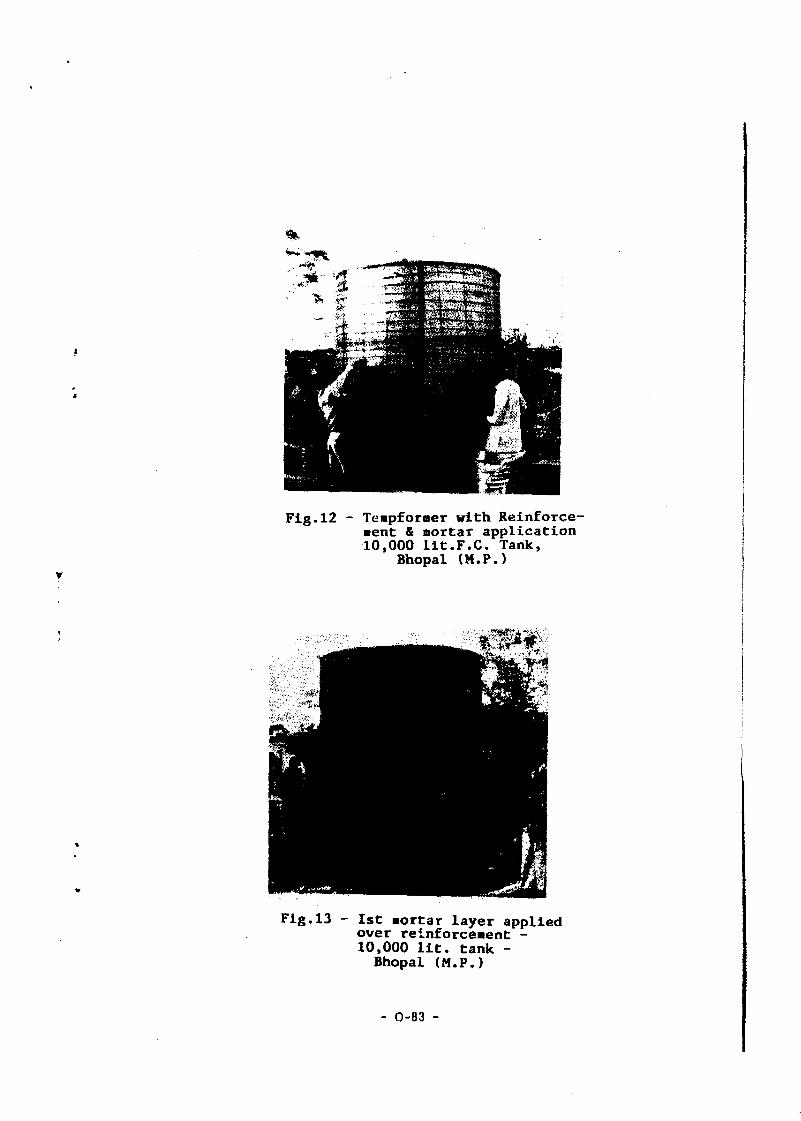
Fig.12 - Teapformer with Reinforce-aent & mortar application10,000 lit.F.C. Tank,
Bhopal (M.P.)
Fig.13 - 1st aortar layer appliedover reinforceaent -10,000 lit. tank -Bhopal (M.P.)
- 0-83 -

Fig. 14 - Marking 4 cutting of two hesiancloth pieces for stitching a sackmould for water tank.
Sack Mould is filled with rice huskand reinforcement cage made over it

3. Sacknould Technique for Saall Tanks :
Sackmould method was originally developed and used in
Thailand for making of mortar (unreinforced) water jars. These jars
have been found to be very useful and can be produced on self-help
basis by villagers without any equipment. Some modifications have
been carried out at SERC in the above technology for making it
suitable for use in Indian villages. The technique is suitable for
domestic storage of drinking water, grains, oilseeds, pulses, seeds
etc. .
A hesian sack mould is stitched and filled with rice
husk/saw dust/waste fodder or fallen dry leaves for obtaining a
shape having internal dimensions of the tank/bin. Wire mesh and
cold drawn wire is cut. and tied over the sack mould. The sack mould
surface is made slightly moist by spraying water and cement sand
mortar mix of 1:2 to 1:3 is applied and impregnated into the
reinforcement cage. The outer surface is finished smooth. This cast
unit is left unplastered for a period of 24 to 36 hours and the
rice husk filled in the sacl mould is then removed out of it. The
empty sack mould is pulled out and the inside of the unit is
cleaned and finished with cement sand mortar. Jars upto 2 M volume
can be cast easily with this technique. Figures 14 & 15 shows
stages of this technique.
Apart from the three processes described at 2(a), 2(b) &
2{c), SERC, Ghaziabad has also developed a process for centrifuging
of F.C. cylindrical units and a vibro pressing method for ta~k
segments. Methods of casting and jointing of segments for RCC base
and ferrocement roofing units have also been developed and used.
All the casting techniques mentioned above have been used for
construction of large number of ferrocement water storage tanks in
India for capacities upto 30,000 litres. The advantages of improved
methods developed at SERC are reduction in dead weight of the tank
by 20 to 50%; reduction in consumption of materials by 307,, better
-finish, shape and compaction of mortar and suitability for factory/'

community level production of tanks, septic tanks and digesters
etc. Apart from the above, a pit lining method has been developed
for underground tanks in laterite or similar soil stratas. The
complete technology, training and process packages are available
from SERC for commercial use.
As an important activity for the National Drinking Water
Mission, Government of India, SERC is undertaking training courses
and demonstrations in construction techniques for Rain Water
Harvesting and Ferrocement Tanks in the different parts of the
country. Eleven such programmes (upto October, 1989) have already
been organised and approximately 600 Engineers and Technicians have
been trained in this technology. Many more training programmes
have been planned. States covered are - Manipur, Meghalaya,
Nagaland, Tripura, Madhya Pradesh, Uttar Pradesh, but participants
from Rajasthan, Gujarat, Karnataka, Andhra Pradesh, Assam and
Maharashtra have also attended these courses.
ACKNOWLEDGEMENTS
The author greatfully acknowledge the guidance received froir
Dr. S.P. Sharma, Director, Structural Engineering Research Centre,
Ghaziabad, (U.P.), India.
The paper is published with the kind permission of Director,
SERC, Ghaziabad.
- 0-74 -
REFERENCES
1. Sharma, P.C., 'Ferroceraent WaCer Tanks for Safe Storage ofDrinking Water1. Seminar on Drinking Water Mission atCSMCRI, Bhavnagar, India, April, 1987.
2. Sharma, P.C., Gopalaratnam, V.S., 'DO IT YOURSELF' book on'Ferrocement Water Tanks'. Published by IFIC, AsianInstitute of Technology, Post Box No.2754, Bangkok,Thailand.
3. Sharma, P.C., 'Developed Casting Technique for CylindricalFerrocement Units'. Proceedings of the Illrd Training Courseon Construction Techniques for Rain Water Harvesting Systemsand Ferrocement Tanks, sponsored by UNICEF, SERC, Ghaziabad,India, November, 1988.
4. Gopalakrishnan, S., Sharma, P.C., Raman, N.V., 'SmallCapacity Ferrocement Water Tanks'. Proceedings of the 8thSession of International Association of Shell Structures(IASS) Committee on Pipes and Tanks, Budapest, Hungary,June, 1978.
5. Sharma, P.C., 'Construction Techniques for FerrocementUnits'. Proceedigns of the Asia and Pacific Training Courseon F.C. Application for Rural Development, Roorkee, India,1984.
6. Surya Kumar, G.V., Sharma, P.C., Gopalakrishnan, S.,'Improvements in or Relating to Precast FerrocementCylindrical Units for Use in Structures like Grain StorageBins, Water Tanks, Biogas Holders and Pipes', SERC, Roorkee,India, Patent No.145250.
7 .Sharma, P.C., 'Ferrocement Structures for Rain WaterHarvesting Schemes' - Moving Technology, Vol.3, No.6,December, 1988.
8. Sharma, P.C., 'Construction Techniques for Ferrocement Tanksfor Rain Water Harvesting1 - Fourth International Conferenceon Rain Water Cistern Systems, Manila, August 2-4, 1989.
9. Design Packages and Guidelines, Vol. I & II, published byNational Drinking Water Mission, Govt. of India for Seminaron Water Harvesting Systems & their Management, Bangalore,December, 1988.
10. Sharma, P.C., 'A Mechanised Process for ProducingFerrocement Roof and Wall Elements', Journal of Ferrocement,Vol. 13, No.l, January, 1983.
- 0-75 -

Fig. 1 - Skeletal Cage for F.C. Water
Fig. 2 - Wire nesh being fixed over Skeletal Cage
- 0-76 -

Fig. 3 - Piece of G.I. sheet held on theinside aesh surface - Mortarbeing applied fron outside
Fig. 4 - Mortar application finishingF.C. Tank, 10,000 Litres -R.P.H.E.D., Jodhpur
0-77

RCINFORCEMENTWIRC MESH ROLL
THICK WOOO OR
nrwooo SCSMMTS
COLLAR WIRE ME1NROLL ON .
M.J. CHANNEL RASEMILO STEEL TUBULARFRAME STANO
ELEVATION
M.S. CNANNCL
WMC MCSN ROLLFOR MAIN 'RCINTOROCMENT
WIRE MESHROLL FOR COLLARREINFORCEMENT
M.S. TUBUtAII SUMO M.S TURULAR STAND
PLAN
Pig. 5 - Seal-Mechanised Process for producingP.C. Cylindrical units-Patented Process
A MflMrEB FMCCIS
- 0-78 -

1-0
119 •
INLET 110 (2Cw THICK)PI»a0CEMCMTWtWHf • I I kf
ROOF UNIT (ICm TH-)FCHROCCMCNTMEICHkM kf-
«#•
OUTLETLIO ( t e n THICK)FCftROCEMCNT
*?
SECTIONAL ELEVATIONS
1 Cm THICK WALL UNITFCRIIO CCMCNTWCIftMT.IOkg-
R.C BASEtlO kft.
ALL DIMENSIONS IN CMS-
HOT TO SCALE
Fig. 6 - Ferroceaent Precast Elements forTanks and Bins
- O-79 -

Fig. 7 - S.E.R.C. Seg.ental Technique forCylindrical Tanks, Bins, SepticTanks & Digesters - various stages
- O-80 -
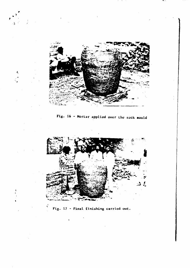
Fig. 16 - Mortar applied over the sack mould
Fig. 17 - Final finishing carried out.


![[Oil]aboveground oil storage tanks 2009](https://img.pdfslide.us/doc/110x75/55a50ed41a28abda588b48e1/oilaboveground-oil-storage-tanks-2009.jpg)