Embed Size (px)
Citation preview
5
Investigations of Thermal Barrier Coatings for Turbine Parts
Alexandr Lepeshkin Central Institute of Aviation Motors
Russia
1. Introduction
Progress in gas-turbine engine (GTE) manufacturing is continuously linked with a rise of operating temperature and stresses of engine gas path elements, especially the turbine parts. More advanced cooling systems, structural materials and thermal barrier coatings (TBC) and other coatings provide the required life and strength reliability of these components. While engines are in use, the necessity arises to repair turbine blades and vanes with a TBC and combustion liners. At the same time, it is difficult to estimate the durability of the turbine blades and combustor components with a TBC and vanes because of the complexity of simulation of the damaging factors acting under service conditions and also because of problems in obtaining the input data required for making such estimations. Therefore, the development of methods for the calculated and experimental investigations thermal barrier coatings, thermophysical and strength properties of TBC and thermal, thermostress state and thermomechanical fatigue engine parts with a TBC is of great importance. While conducting these investigations, the main tasks are the comparative estimation of the design and production (or repair) process solutions and verification of the methods of calculation of the durability of engine parts with a TBC. To provide simulation of loading conditions for the hot engine parts with a TBC under service conditions, the test procedure shall ensure the possibility of cyclic surface heating of the object under testing (simulating its heating in hot gas flow) up to temperatures of 1150 °C and more at heating rates of 150-200 °C/s and subsequent cooling. Also it is desirable to have the possibility for mechanical loading of parts and TBC with a required phase shift between mechanical load and temperature.
2. Ceramic thermal barrier coatings and heating methods
For the purpose of providing the serviceability of high-efficiency aircraft gas turbine engines and gas turbine plants of new generations, it is necessary to improve existing cooling systems, to design new refractory and ceramic high-temperature materials, and to enhance the protection of parts of the high-temperature section of gas turbine engines with the use of heat-resistant and refractory coatings [1-12]. Improvement of the internal heat removal system leads to the transformation of parts into heat exchangers, which is accompanied by an increase in the thermal stress and a decrease in the thermal cycle life. Currently widely used refractory materials based on nickel usually operate in gas turbine engines at maximum allowable temperatures. The gas temperature can be allowed to increase only in
www.intechopen.com
Ceramic Coatings – Applications in Engineering
130
the case where care is taken to restrict the passage of heat flow through the wall of the part. The heat flow from the gas to the wall of the base material of the part can be considerably reduced by means of either using a well-organized protective cooling without ejection or depositing thermal barrier coatings on the surface of the most strongly heated regions of the part.
2.1 Ceramic thermal barrier coatings
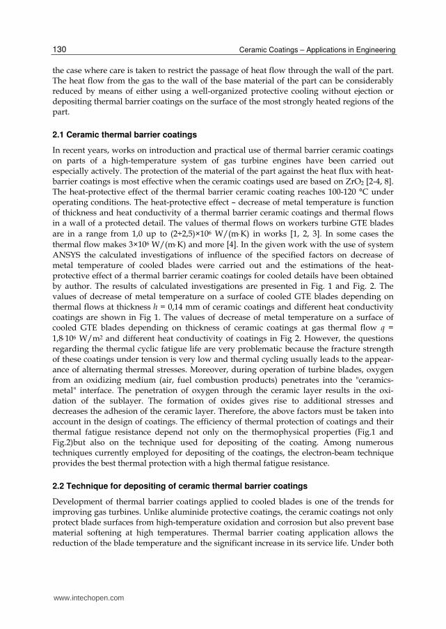
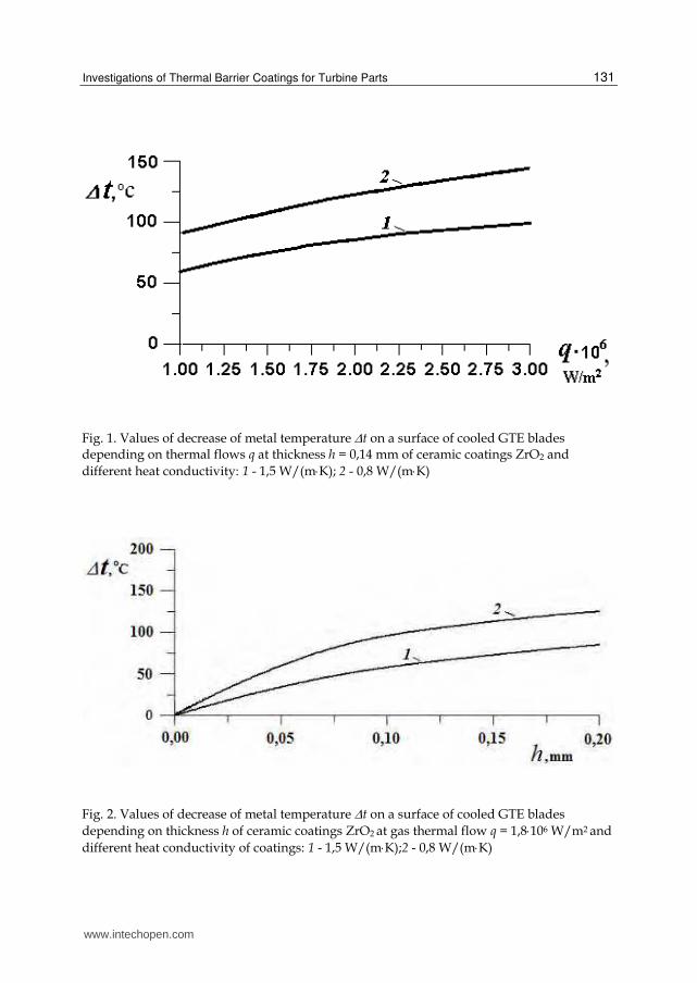
In recent years, works on introduction and practical use of thermal barrier ceramic coatings on parts of a high-temperature system of gas turbine engines have been carried out especially actively. The protection of the material of the part against the heat flux with heat-barrier coatings is most effective when the ceramic coatings used are based on ZrO2 [2-4, 8]. The heat-protective effect of the thermal barrier ceramic coating reaches 100-120 °C under operating conditions. The heat-protective effect – decrease of metal temperature is function of thickness and heat conductivity of a thermal barrier ceramic coatings and thermal flows in a wall of a protected detail. The values of thermal flows on workers turbine GTE blades
are in a range from 1,0 up to (2÷2,5)×106 W/(mК) in works [1, 2, 3]. In some cases the
thermal flow makes 3×10⁶ W/(mК) and more [4]. In the given work with the use of system ANSYS the calculated investigations of influence of the specified factors on decrease of metal temperature of cooled blades were carried out and the estimations of the heat-protective effect of a thermal barrier ceramic coatings for cooled details have been obtained by author. The results of calculated investigations are presented in Fig. 1 and Fig. 2. The values of decrease of metal temperature on a surface of cooled GTE blades depending on thermal flows at thickness h = 0,14 mm of ceramic coatings and different heat conductivity coatings are shown in Fig 1. The values of decrease of metal temperature on a surface of cooled GTE blades depending on thickness of ceramic coatings at gas thermal flow q =
1,8106 W/m2 and different heat conductivity of coatings in Fig 2. However, the questions regarding the thermal cyclic fatigue life are very problematic because the fracture strength of these coatings under tension is very low and thermal cycling usually leads to the appear-ance of alternating thermal stresses. Moreover, during operation of turbine blades, oxygen from an oxidizing medium (air, fuel combustion products) penetrates into the "ceramics-metal" interface. The penetration of oxygen through the ceramic layer results in the oxi-dation of the sublayer. The formation of oxides gives rise to additional stresses and decreases the adhesion of the ceramic layer. Therefore, the above factors must be taken into account in the design of coatings. The efficiency of thermal protection of coatings and their thermal fatigue resistance depend not only on the thermophysical properties (Fig.1 and Fig.2)but also on the technique used for depositing of the coating. Among numerous techniques currently employed for depositing of the coatings, the electron-beam technique provides the best thermal protection with a high thermal fatigue resistance.
2.2 Technique for depositing of ceramic thermal barrier coatings
Development of thermal barrier coatings applied to cooled blades is one of the trends for improving gas turbines. Unlike aluminide protective coatings, the ceramic coatings not only protect blade surfaces from high-temperature oxidation and corrosion but also prevent base material softening at high temperatures. Thermal barrier coating application allows the reduction of the blade temperature and the significant increase in its service life. Under both
www.intechopen.com
Investigations of Thermal Barrier Coatings for Turbine Parts
131
Fig. 1. Values of decrease of metal temperature t on a surface of cooled GTE blades depending on thermal flows q at thickness h = 0,14 mm of ceramic coatings ZrO2 and
different heat conductivity: 1 - 1,5 W/(mК); 2 - 0,8 W/(mК)
Fig. 2. Values of decrease of metal temperature t on a surface of cooled GTE blades
depending on thickness h of ceramic coatings ZrO2 at gas thermal flow q = 1,8106 W/m2 and
different heat conductivity of coatings: 1 - 1,5 W/(mК);2 - 0,8 W/(mК)
www.intechopen.com

Ceramic Coatings – Applications in Engineering
132
steady-state and transient conditions, the application of ceramic TBC can diminish temperature gradients over the blade surfaces as well as reduce thermal stresses in them. A typical design of a TBC is presented in Fig. 3. The ceramic coating deposited directly on the superalloy surface does not show the required service life. Penetration of oxygen through the ceramic layer to the superalloy surface results in its quick oxidation and in spallation of the ceramic layer. That is why, as a rule, a TBC consists of at least two layers. An inner aluminide heat-resistant bond coat may be formed by different techniques. It may be either a diffusion or an overlay coating, depending on the requirements of its physical-mechanical properties and protection targets. The requirements of bond coat properties and protective coatings properties are much the same, yet the bond coat should meet some special requirements. First of all, it must be highly heat resistant; the oxides formed on its surface should have high adhesion to both the bond coat and the outer ceramic layer. When choosing a bond coat composition, one should pay special attention to its yttrium content as well as to the contents of the other elements, which guarantee high oxide adhesion to the surface and reactive element effect (Stringer, 1989). It is of special importance for bond coats deposited by the electron beam technique, because their yttrium contents depend on the yttrium content of the liquid bath and vary within wide limits (Malashenko et al., 1997). In this case, the required yttrium content of 0.2 to 0.3% is guaranteed by different technological procedures, such as direct yttrium addition to the liquid bath (Tamarin & Kachanov, 2008). Under these conditions, it is noteworthy that high yttrium contents of the liquid bath cause slag formation on its surface, thus resulting in occurrence of microdrops. These microdrops on the bond coat surface may provoke defects in the ceramic coating (layer).
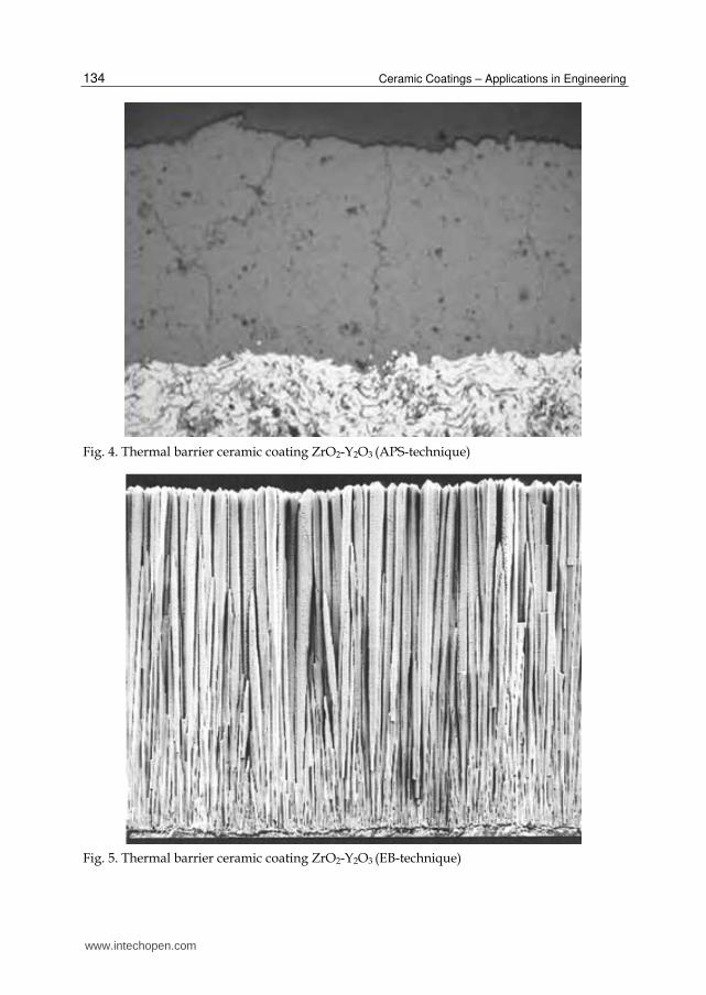
It should be taken into consideration that TBCs are usually applied to the blades of high-temperature turbines. The blades of such turbines feature directionally solidified or single-crystal structures, thin walls, and high cooling efficiency. Under service conditions, high thermal stresses and strains arise in these blades, especially in their surface layers. That is why thermomechanical fatigue characteristics are as important in choosing a bond coat composition as its heat resistance. During thermal cycling, the bond coat should not experience considerable plastic strain. For example, the effect of a "rippled" blade surface (Fig. 4) always entails spallation of the ceramic layer. The outer zirconium oxide/yttrium oxide (ZrO2-Y2O3) system base ceramic layer can-be applied by two techniques (Fig 4 and Fig 5): air plasma spraying of powders (APS-technique) or vapor condensation at electron beam evaporation of ceramic pellets (EB-technique). For this system, ceramic coating service life depends on Y2O3 content. The ZrO2-(6 to 9%) Y2O3 compositions are usually applied, because they have demonstrated maximum service lives in the tests carried out (Miller, 1983 &Stecura, 1986). However, one should bear in mind the fact that the coating service life depends not only on its chemical composition but also on its structure and adhesive strength at the ceramic layer/bond coat interface, which depends on deposition technique. For coatings deposited by different techniques, the optimal chemical compositions may be other than that stated previously. The ceramic layer deposition technique determines such characteristics as ceramic layer structure and adhesive strength, its corresponding service life, thermal stresses in the ceramic layer, and its surface roughness. The main difficulty in designing TBCs for turbine blades lies in the combination of the ceramics on the blade surface and the superalloy that they are made of. At heating-up/cooling-down cycling, considerable difference between the ceramics
and superalloy expansion coefficients~ 5.0 10-6 1/°C causes the generation of high
www.intechopen.com

Investigations of Thermal Barrier Coatings for Turbine Parts
133
thermal stresses in ceramics, which in turn results in ceramic layer spalling from the surface. To reduce thermal stresses, various technological procedures are used. In the ce-ramic layer deposited by the APS technique, special heat treatment is used to form a network of microcracks that break the ceramics into isolated fragments (Ruckle & Duvall, 1984). In the ceramic layer deposited by the EB technique, some specific columnar structure is formed that is readily fragmentizing when tensile stresses arise in (Strangman, 1982). The point crucial to success in the development of TBCs lies in obtaining the required adhesive strength of the ceramic coating/heat-resistant bond coat, providing for holding of the ceramics on the blade surface during all the blade service life. As a rule, in aircraft engine manufacturing, the technique of plasma deposition is used for nozzle vanes; in aircraft engine turbine blades, the EB technique is considered to be preferable. This is due to the fact that the following properties can be rendered ramie layer. The specific columnar structure, with the crystallites oriented perpendicular to the surface, forms in the ceramic vapor-deposited coating. In the case of tensile stresses, the ceramic layer is readily fragmentizing, thus reducing ceramic tearing stress during thermal cycling. In the temperature range of 850 to 950 °C, which is below the blade heating temperature at ceramic layer deposition, compressive stresses arise in it.
Fig. 3. Thermal barrier coating system: 1 – ceramic coating ZrO2-8%Y2O3, 2 – bond coating MCrAlY, 3 - superalloy
www.intechopen.com
Ceramic Coatings – Applications in Engineering
134
Fig. 4. Thermal barrier ceramic coating ZrO2-Y2O3 (APS-technique)
Fig. 5. Thermal barrier ceramic coating ZrO2-Y2O3 (EB-technique)
www.intechopen.com
Investigations of Thermal Barrier Coatings for Turbine Parts
135
Their generation is due to the different values of the ceramic and superalloy thermal expansion coefficients. These stresses do not relax on subsequent process annealing and under service conditions. The adhesive strength of the ceramic coating is controlled by physical-chemical reactions occurring between the ceramics and the metallic bond coat. As-deposited ceramic coating adhesive strength is above 50-100 MPa. The surface
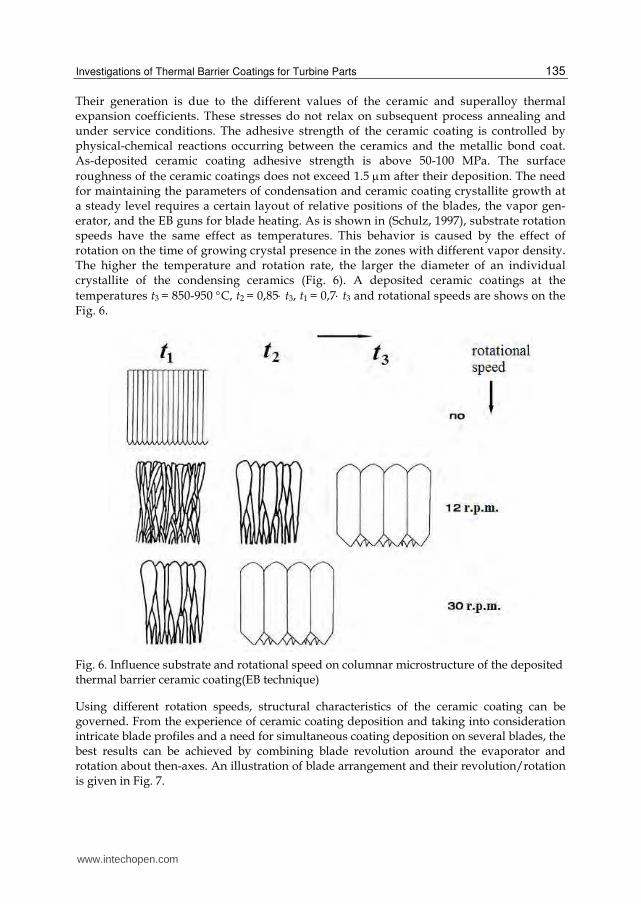
roughness of the ceramic coatings does not exceed 1.5 m after their deposition. The need for maintaining the parameters of condensation and ceramic coating crystallite growth at a steady level requires a certain layout of relative positions of the blades, the vapor gen-erator, and the EB guns for blade heating. As is shown in (Schulz, 1997), substrate rotation speeds have the same effect as temperatures. This behavior is caused by the effect of rotation on the time of growing crystal presence in the zones with different vapor density. The higher the temperature and rotation rate, the larger the diameter of an individual crystallite of the condensing ceramics (Fig. 6). A deposited ceramic coatings at the
temperatures t3 = 850-950 C, t2 = 0,85 t3, t1 = 0,7 t3 and rotational speeds are shows on the Fig. 6.
Fig. 6. Influence substrate and rotational speed on columnar microstructure of the deposited thermal barrier ceramic coating(EB technique)
Using different rotation speeds, structural characteristics of the ceramic coating can be governed. From the experience of ceramic coating deposition and taking into consideration intricate blade profiles and a need for simultaneous coating deposition on several blades, the best results can be achieved by combining blade revolution around the evaporator and rotation about then-axes. An illustration of blade arrangement and their revolution/rotation is given in Fig. 7.
www.intechopen.com

Ceramic Coatings – Applications in Engineering
136
Fig. 7. Scheme for depositing of ceramic thermal barrier coatings (EB-technique) : 1 – rotor, 2 – blades, 3 – ceramic, 4 – electron beam gun of evaporator, 5 - electron beam gun for blade heating
The fixture in use revolves in the vapor flow with the speed of ~ 12 rpm. At each fixture rev-
olution the blades additionally revolve once around the fixture axis. The choice of blade ro-
tation conditions depends also on the requirements to the ceramic coating thickness and its
spread over the blade surface. The ceramic structure features the pronounced texture of
growth perpendicular to the surface (Fig. 5). Some individual ceramics crystals are
preferably oriented in a [100] direction. Their diameters are in the range of 0.6 to 1.2 m.
They do not vary much along the full crystal lengths. Ceramic coating crystallites should
have high cohesive strength and withstand an attack of a high-temperature gas flow. That is
why the ceramic evaporation process feature is a requirement to its continuity. Unlike
metallic bond coat deposition, in which no process interruption is harmful for the coating
quality, any interruption of ceramic coating deposition forms an additional boundary, in the
ceramics. The strength of this boundary is much lower than the crystallite strength. Thus,
under these conditions, the ceramic coating will never meet the requirements of its
properties. In the case of any pause in ceramics evaporation, all the lot of blades being
coated are rejected and sent to ceramic layer removal procedure, followed by its
redeposition. When ceramic layer deposition is carried to its completion, the blades are
removed from the unit and passed to heat treatment. After treatment its color changes from
dark gray to white. Two-step annealing does not change ceramic layer structure and phase
composition. Check operations in the TBC quality control include a visual inspection to
guarantee that its surface is free from ceramics droplets; measurements of ceramic layer
thickness in the specified blade zones; and a bend test of a flat check sample on the radius of 3
and 10 mm to assess its adhesive strength. On its bending to the angle of 90°, ceramic
coating spallation is prohibitive. Some cracking of the ceramic coating is allowed. The
results of thermal conductivity studies for different ceramic coatings formed by the EB
technique are presented in (Nichols et al., 2001). On the basis of the studies (Lawson et al.,
1996), a two-zone model of a ceramic coating is suggested. Thermal conductivity of a dense,
inner ceramic zone that forms at the starting moment of condensation is much lower than
thermal conductivity of an outer zone (Fig. 8). This effect is attributed to the presence of
numerous boundaries in the dense zone. Therefore, for reducing thermal conductivity of EB
www.intechopen.com
Investigations of Thermal Barrier Coatings for Turbine Parts
137
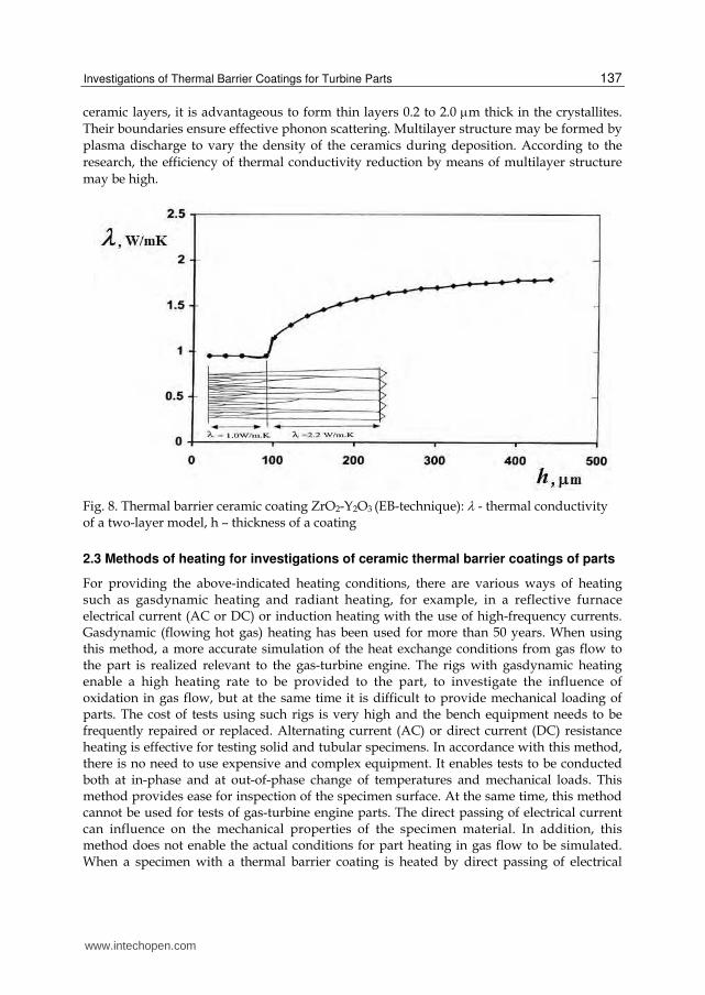
ceramic layers, it is advantageous to form thin layers 0.2 to 2.0 m thick in the crystallites.
Their boundaries ensure effective phonon scattering. Multilayer structure may be formed by
plasma discharge to vary the density of the ceramics during deposition. According to the
research, the efficiency of thermal conductivity reduction by means of multilayer structure
may be high.
Fig. 8. Thermal barrier ceramic coating ZrO2-Y2O3 (EB-technique): - thermal conductivity of a two-layer model, h – thickness of a coating
2.3 Methods of heating for investigations of ceramic thermal barrier coatings of parts
For providing the above-indicated heating conditions, there are various ways of heating such as gasdynamic heating and radiant heating, for example, in a reflective furnace electrical current (AC or DC) or induction heating with the use of high-frequency currents. Gasdynamic (flowing hot gas) heating has been used for more than 50 years. When using this method, a more accurate simulation of the heat exchange conditions from gas flow to the part is realized relevant to the gas-turbine engine. The rigs with gasdynamic heating enable a high heating rate to be provided to the part, to investigate the influence of oxidation in gas flow, but at the same time it is difficult to provide mechanical loading of parts. The cost of tests using such rigs is very high and the bench equipment needs to be frequently repaired or replaced. Alternating current (AC) or direct current (DC) resistance heating is effective for testing solid and tubular specimens. In accordance with this method, there is no need to use expensive and complex equipment. It enables tests to be conducted both at in-phase and at out-of-phase change of temperatures and mechanical loads. This method provides ease for inspection of the specimen surface. At the same time, this method cannot be used for tests of gas-turbine engine parts. The direct passing of electrical current can influence on the mechanical properties of the specimen material. In addition, this method does not enable the actual conditions for part heating in gas flow to be simulated. When a specimen with a thermal barrier coating is heated by direct passing of electrical
www.intechopen.com
Ceramic Coatings – Applications in Engineering
138
current, the coating temperature is lower than the base material temperature. Radiant heating of parts is of certain use when conducting the thermocyclic tests for specimens with a TBC. In so doing the surface is heated at a high rate, however, because of radiation focusing during test of a part (or a part model) it is difficult to simulate the required temperature field. Additionally, the heaters have a low cyclic lifetime. Evidently, induction heating with the use of high-frequency currents in the surface of a part is of greatest use to heat parts and models of parts when conducting tests for thermomechanical fatigue. Such a method may be used to test both standard specimens and engine parts. When it is used, the surface part heating realized under service conditions is well simulated. In so doing, heat releases directly in the part. There is no need to use expensive heating equipment, and the equipment used features of high durability. The mechanical loading device can be used in the rig with inductor heating. It provides the possibility of conducting thermomechanical fatigue tests of turbine blades. In so doing, with the use of a special inductor the temperature field is simulated for the blade section under the service conditions of which the strength margin is minimum and with the use of a suitable loading device, the centrifugal load is simulated in this section. It is worth noting that induction heating is only effective for testing of metallic alloys. For tests of parts made of ceramic materials, it is recommended in a number of papers to use dielectric heating (in Mega Hertz frequency range) or heating with the use of a susceptor. In the latter case, it is not possible to provide suitable heat-up rates for the temperature of the part. As conducted investigations showed that when using currents of more than 400 kHz to heat a metallic part with a TBC, both heating of metal located under the external layer coating and the effective heating of the dielectric (TBC) take place. Correlation of heat shared depends on the thermophysical properties of the base and coating materials and the frequency at which heating is performed, and a number of other factors. The experiments showed that the ceramic ZrO2 - based thermal barrier coatings on specimens and parts made of high-temperature nickel-based alloys are effectively heated at frequencies between 0.4 and 2.0 MHz. Use of a higher frequency requires a complicated rig design. Consequently, it seems that in spite of a lack of data concerning the absence of a knowledge of the influence of induction heating on mechanical properties of the materials under investigation, this method of heating can be successfully used for tests of specimens and engine parts (primarily for comparative tests for selection of coatings and materials, design solution, manufacture and repair of engine parts with a TBC by production processes). The cost of the tests conducted with the use of high-frequency heating is by an order lower than the cost of the tests conducted on a gasdynamic rig.
3. Investigations of ceramic thermal barrier coatings of parts with the use of HF induction heating
3.1 HF induction heating of ceramic thermal barrier coatings of parts
At present, the cyclic fatigue life of thermal barrier coatings in the course of their
development has been studied using radiant heating with a low rate (less than 20 K/s),
which does not correspond to actual operating conditions. At such low heating rates,
thermal stresses are almost completely absent and the main damage factor is the oxidation
of a sublayer, which leads to spalling of the coating. Actually, these processes are heat
resistance tests at variable temperatures. Under real conditions, the rate of change in the
www.intechopen.com
Investigations of Thermal Barrier Coatings for Turbine Parts
139
temperature of parts lies in the range 100-200 K/s. In this case, there arise cyclic thermal stresses and deformations of the base material and coating, which are accompanied by the appearance of alternating stresses. The results of tests for thermal fatigue of parts with thermal barrier coatings can differ significantly from the results of tests for cyclic heat resistance, which have been obtained by developers at a low rate of change in temperature. Therefore, in the design of thermal barrier coatings, it is necessary to investigate their heat resistance together with a protected material under the conditions providing high rates of heating and cooling. The tests performed in a gas-dynamic flow are expansive and require a long time. The high-frequency induction heating is significantly lower in cost and requires a shorter time. The process of high-frequency heating involves not only induction heating of conductive materials but also heating of dielectrics, including ceramic materials. The dynamics of heating of the coating and the base material depends on the electrophysical and thermophysical properties of the material, its volume, the cooling conditions, the rate of heating of the object, the dielectric properties of the ceramic coating, and the frequency of the electric current used for heating. The calculated simulation of the heating conditions for parts with thermal barrier ceramic coatings has not been adequately developed as compared to thermal calculations of the parts operating in a gas dynamic flow. More reliable data on the temperature state of parts with thermal barrier ceramic coatings during their heating in a high-frequency electromagnetic field and on their heat resistance can be obtained from experimental investigations. In order to create prerequisites that are necessary for the development of computational methods used for determining the thermal and thermostressed states of parts with thermal barrier coatings in the course of their heating in a high-frequency electromagnetic field and for the experimental evaluation of the thermal cyclic fatigue life of these parts, in this work we set the problem of the development of a technique for high-frequency heating and thermophysical measurements in tests of blades and models of other parts with thermal barrier coatings based on zirconia. The develop of a design-experiment method is necessary for modeling of high-frequency induction heating and determination of fatigue and thermophysical measurements in thermal cycling tests of blades of gas turbine engines, to perform experimental investigations on the determination of the temperature state of blades and models with zirconia thermal barrier coatings with the use of a thermal vision system during high-frequency heating of parts with ceramic coatings, to determine the ratio between the processes of high-frequency and dielectric heatings, to obtain a generalized dependence of the temperature gradient across the ceramic coating thickness on the frequency of the electric current from multivariant calculations, and to compare the thermal cyclic fatigue lives of parts with a thermal barrier coating and without it.
3.2 Technique and results of investigations
The design-experiment method involves complex interrelated physical processes (such as heating of metal and ceramic materials in a high-frequency electromagnetic field, dielectric heating of the ceramic material, and interactions of nonstationary fields of temperatures and thermal stresses in a metal-ceramic part with cooling holes) and takes into account the electrophysical and thermophysical properties of the materials in thermal cyclic tests [Kuvaldin &Lepeshkin, 2006). New tasks on the determination of the ratio between the processes of high-frequency and dielectric heatings and on the identification of the dielectric heating effect and its influence on the distributions of heat fluxes and tem-
www.intechopen.com
Ceramic Coatings – Applications in Engineering
140
peratures in a metal-ceramic part are set in computational and experimental studies. By using multivariant calculations, it is necessary to obtain a generalized dependence of the temperature gradient across the ceramic coating thickness on the frequency of the electric current.
3.2.1 Numerical simulation
The computational part of the method consists in sequentially solving the following
problems: the electromagnetic problem based on the Maxwell equations, the transient heat problem based on the solution of the heat conduction equation, and the problem of
determination of the thermostressed state. The first problem was solved with due regard for the recommendations proposed in (Kuvaldin & Lepeshkin, 2006). By solving this problem
(taking into account the gap between the inductor and the part and the electric current fre-quency of 440 kHz), we determined the distribution of internal heat sources (specific heat
power) over the thickness of the base metal (the refractory nickel alloy of the flame tube) with an intermediate refractory metal coating NiCoCrAlY, as well as in the ceramic
coating due to the induction heating (as a result of the change in the electrical resistivity ofzirconium oxide with an increase in temperature) and dielectric heating (as a result of
the change in the permittivity and the dielectric loss tangent with an increase in temperature). The obtained distributions of internal heat sources are nonstationary; i.e.,
they depend on the heating time. During the solution of the coupled electromagnetic and heat problems at each computational step, the value of the current temperature was
transferred from the module of the solution of the heat problem to the module of the solution of the electromagnetic problem in order to correct the electrophysical properties of
the materials. The computational investigations allow one to refine the thermal and thermostressed states of thermal barrier ceramic coatings on cooled blades and models
during high-frequency induction heating with the inclusion of dielectric heating. The initial data used in the performed calculations were electrophysical, thermophysical, and strength
properties of the ceramic coatings and the material of cooled parts, the characteristics of bench conditions for heating and cooling, and the parameters of the test thermal cycle. The
electrophysical and dielectric properties of the ceramic (zirconia) coating were taken from (Rubashev at al., 1980), and the electrophysical, thermophysical, and strength properties of
the ceramic coatings were taken from (Tamarin & Kachanov, 2008). The parameters of the
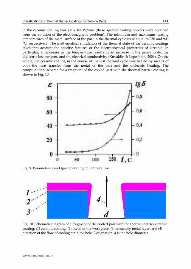
permittivity and dielectric loss tangent tg of a zirconium oxide depending on temperature
are shown in Fig. 9. Electrical resistivity of a zirconium oxide makes at the temperatures: 100
C - 1011 Ohmcm,1000 C - 10 Ohmcm.
The calculations performed by author using the finite element method implemented in the ANSYS program and the distribution of the heat flux from the inductor between the zirconia coating and the metal of the cooled part at an induction current frequency of 440 kHz made it possible to investigate the nonstationary thermal state of the coating and the cooled part with the inclusion of the parameters of the test thermal cycle. The boundary conditions for the solution to the heat problem were as follows: the temperature of the ambient air was 20 °C, the heat-transfer coefficients of the ambient air were equal to 20-30W/(m2 K), the heat-transfer coefficients of the cooled air inside the model of a flame tube were equal to 1800-2000 W/(m2 K) (according to the experimental data), the specific heating power on the surface of the refractory metal coating was 9 x 10⁵ W/cm2, and the specific heating power
www.intechopen.com
Investigations of Thermal Barrier Coatings for Turbine Parts
141
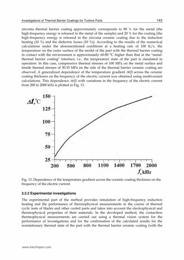
in the ceramic coating was 1.8 x 10⁵ W/cm2 (these specific heating powers were obtained from the solution of the electromagnetic problem). The minimum and maximum heating temperatures of the metal surface of the part in the thermal cycle were equal to 350 and 900 °C, respectively. The mathematical simulation of the thermal state of the ceramic coatings takes into account the specific features of the electrophysical properties of zirconia. In particular, an increase in the temperature results in an increase in the permittivity, the dielectric loss tangent, and the electrical conductivity (Kuvaldin & Lepeshkin, 2006). On the whole, the ceramic coating in the course of the test thermal cycle was heated by means of both the heat transfer from the metal of the part and the dielectric heating. The computational scheme for a fragment of the cooled part with the thermal barrier coating is shown in Fig. 10.
Fig. 9. Parameters and tg depending on temperature
Fig. 10. Schematic diagram of a fragment of the cooled part with the thermal barrier ceramic coating: (1) ceramic coating, (2) metal of the workpiece, (3) refractory metal layer, and (4) direction of the flow of cooling air in the hole. Designation: d is the hole diameter
www.intechopen.com

Ceramic Coatings – Applications in Engineering
142
The performed calculations of the nonstationary thermal and thermostressed states of the models of cooled parts with thermal barrier ceramic coatings (Fig. 11 and Fig. 12) have demonstrated that, at the maximum temperature of the thermal cycle, the temperature of the outer surface of the ceramic coating at the end of heating is higher than the temperature of the metal and, consequently, there arise temperature gradients across the ceramic coating thickness.
Fig. 11. Calculated temperature distribution of the fragment of the cooled part with the
thermal barrier ceramic coating in the region of the cooling hole
Fig. 12. Calculated thermostress distribution of the fragment of the cooled part with the
thermal barrier ceramic coating in the region of the cooling hole
The temperature gradients depend on the thermal conductivity coefficient, the coating thickness, and the heat loss due to the environment on the surface of the coating. The heat losses were calculated taking into account the convective heat exchange, the radiative heat exchange, and the maximum experimental temperature of uncooled plates of the inductor (300 °C) at the end of heating in the first stage of the thermal cycle. At an induction current frequency of 440 kHz and taking into account the ratios between the heated masses of the base material from the refractory alloy and the coating, as well as their electrophysical and thermophysical properties and cooling conditions, the calculated distribution of the high-frequency electromagnetic energy over the sample from the nickel-based alloy with the
www.intechopen.com
Investigations of Thermal Barrier Coatings for Turbine Parts
143
zirconia thermal barrier coating approximately corresponds to 80 % for the metal (the high-frequency energy is released in the metal of the sample) and 20 % for the coating (the high-frequency energy is released in the zirconia ceramic coating due to the induction heating (10 %) and the dielectric losses (10 %)). According to the results of the numerical calculations under the aforementioned conditions at a heating rate of 100 K/s, the temperature on the outer surface of the model of the part with the thermal barrier coating in contact with the environment is approximately 60-80 °C higher than that at the "metal-thermal barrier coating" interface; i.e., the temperature state of the part is simulated in operation. In this case, compressive thermal stresses of 100 MPa on the metal surface and tensile thermal stresses of 30-35 MPa on the side of the thermal barrier ceramic coating are
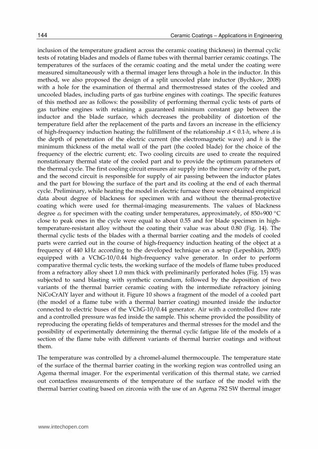
observed. A generalized dependence of the temperature gradient t(f) across the ceramic coating thickness on the frequency of the electric current was obtained using multivariant
calculations. This dependence t(f) with variations in the frequency of the electric current from 200 to 2000 kHz is plotted in Fig. 13.
Fig. 13. Dependence of the temperature gradient across the ceramic coating thickness on the frequency of the electric current
3.2.2 Experimental investigations
The experimental part of the method provides simulation of high-frequency induction heating and the performance of thermophysical measurements in the course of thermal cyclic tests of blades and other cooled parts and takes into account the electrophysical and thermophysical properties of their materials. In the developed method, the contactless thermophysical measurements are carried out using a thermal vision system for the performance of investigations and for the confirmation of the calculated results for the nonstationary thermal state of the part with the thermal barrier ceramic coating (with the
www.intechopen.com
Ceramic Coatings – Applications in Engineering
144
inclusion of the temperature gradient across the ceramic coating thickness) in thermal cyclic tests of rotating blades and models of flame tubes with thermal barrier ceramic coatings. The temperatures of the surfaces of the ceramic coating and the metal under the coating were measured simultaneously with a thermal imager lens through a hole in the inductor. In this method, we also proposed the design of a split uncooled plate inductor (Bychkov, 2008) with a hole for the examination of thermal and thermostressed states of the cooled and uncooled blades, including parts of gas turbine engines with coatings. The specific features of this method are as follows: the possibility of performing thermal cyclic tests of parts of gas turbine engines with retaining a guaranteed minimum constant gap between the inductor and the blade surface, which decreases the probability of distortion of the temperature field after the replacement of the parts and favors an increase in the efficiency
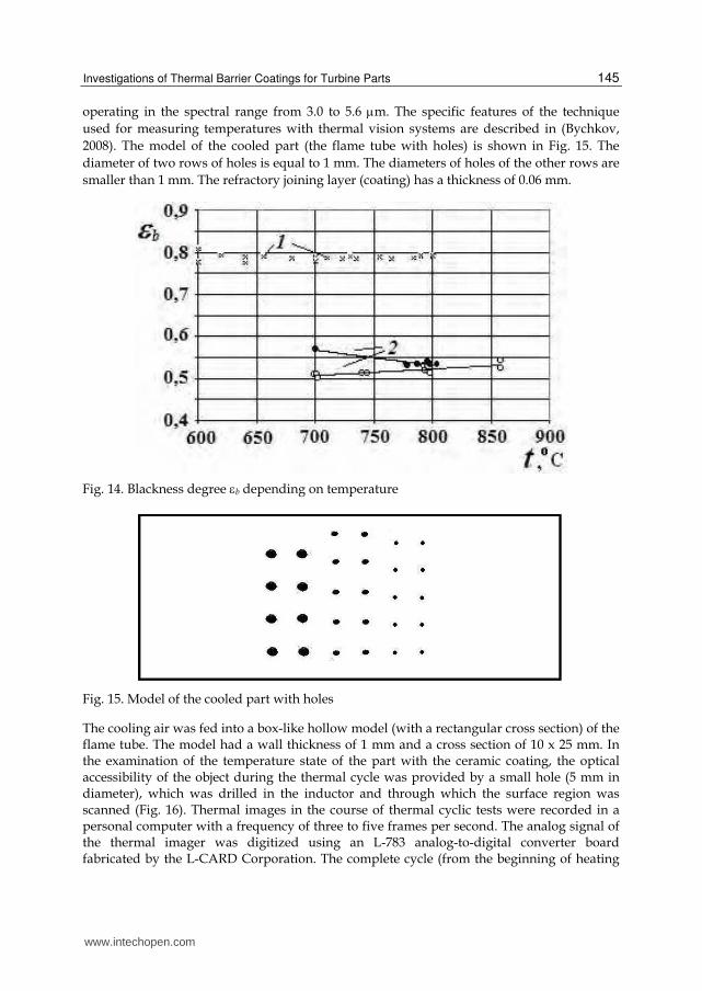
of high-frequency induction heating; the fulfillment of the relationship < 0.1h, where is the depth of penetration of the electric current (the electromagnetic wave) and h is the minimum thickness of the metal wall of the part (the cooled blade) for the choice of the frequency of the electric current; etc. Two cooling circuits are used to create the required nonstationary thermal state of the cooled part and to provide the optimum parameters of the thermal cycle. The first cooling circuit ensures air supply into the inner cavity of the part, and the second circuit is responsible for supply of air passing between the inductor plates and the part for blowing the surface of the part and its cooling at the end of each thermal cycle. Preliminary, while heating the model in electric furnace there were obtained empirical data about degree of blackness for specimen with and without the thermal-protective coating which were used for thermal-imaging measurements. The values of blackness
degree b for specimen with the coating under temperatures, approximately, of 850900 С close to peak ones in the cycle were equal to about 0.55 and for blade specimen in high-temperature-resistant alloy without the coating their value was about 0.80 (Fig. 14). The thermal cyclic tests of the blades with a thermal barrier coating and the models of cooled parts were carried out in the course of high-frequency induction heating of the object at a frequency of 440 kHz according to the developed technique on a setup (Lepeshkin, 2005) equipped with a VChG-10/0.44 high-frequency valve generator. In order to perform comparative thermal cyclic tests, the working surface of the models of flame tubes produced from a refractory alloy sheet 1.0 mm thick with preliminarily perforated holes (Fig. 15) was subjected to sand blasting with synthetic corundum, followed by the deposition of two variants of the thermal barrier ceramic coating with the intermediate refractory joining NiCoCrAlY layer and without it. Figure 10 shows a fragment of the model of a cooled part (the model of a flame tube with a thermal barrier coating) mounted inside the inductor connected to electric buses of the VChG-10/0.44 generator. Air with a controlled flow rate and a controlled pressure was fed inside the sample. This scheme provided the possibility of reproducing the operating fields of temperatures and thermal stresses for the model and the possibility of experimentally determining the thermal cyclic fatigue life of the models of a section of the flame tube with different variants of thermal barrier coatings and without them.
The temperature was controlled by a chromel-alumel thermocouple. The temperature state
of the surface of the thermal barrier coating in the working region was controlled using an
Agema thermal imager. For the experimental verification of this thermal state, we carried
out contactless measurements of the temperature of the surface of the model with the
thermal barrier coating based on zirconia with the use of an Agema 782 SW thermal imager
www.intechopen.com
Investigations of Thermal Barrier Coatings for Turbine Parts
145
operating in the spectral range from 3.0 to 5.6 m. The specific features of the technique
used for measuring temperatures with thermal vision systems are described in (Bychkov,
2008). The model of the cooled part (the flame tube with holes) is shown in Fig. 15. The
diameter of two rows of holes is equal to 1 mm. The diameters of holes of the other rows are
smaller than 1 mm. The refractory joining layer (coating) has a thickness of 0.06 mm.
Fig. 14. Blackness degree b depending on temperature
Fig. 15. Model of the cooled part with holes
The cooling air was fed into a box-like hollow model (with a rectangular cross section) of the flame tube. The model had a wall thickness of 1 mm and a cross section of 10 x 25 mm. In the examination of the temperature state of the part with the ceramic coating, the optical accessibility of the object during the thermal cycle was provided by a small hole (5 mm in diameter), which was drilled in the inductor and through which the surface region was scanned (Fig. 16). Thermal images in the course of thermal cyclic tests were recorded in a personal computer with a frequency of three to five frames per second. The analog signal of the thermal imager was digitized using an L-783 analog-to-digital converter board fabricated by the L-CARD Corporation. The complete cycle (from the beginning of heating
www.intechopen.com
Ceramic Coatings – Applications in Engineering
146
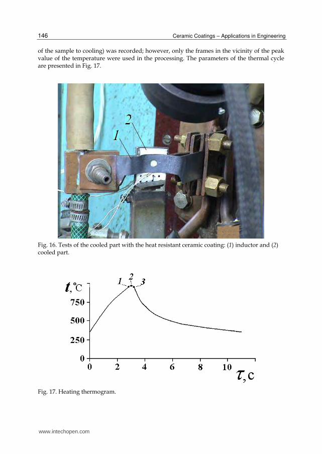
of the sample to cooling) was recorded; however, only the frames in the vicinity of the peak value of the temperature were used in the processing. The parameters of the thermal cycle are presented in Fig. 17.
Fig. 16. Tests of the cooled part with the heat resistant ceramic coating: (1) inductor and (2) cooled part.
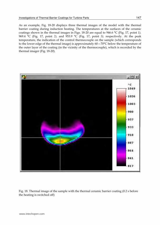
Fig. 17. Heating thermogram.
www.intechopen.com
Investigations of Thermal Barrier Coatings for Turbine Parts
147
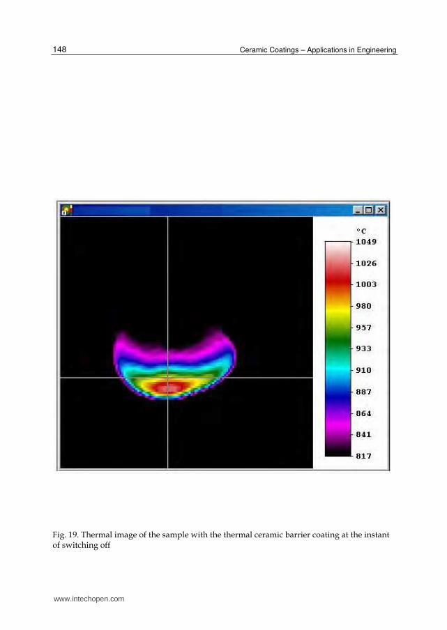
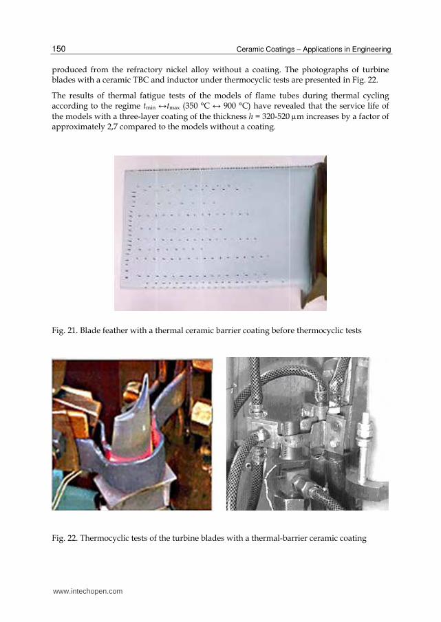
As an example, Fig. 18-20 displays three thermal images of the model with the thermal barrier coating during induction heating. The temperatures at the surfaces of the ceramic coatings shown in the thermal images in Figs. 18-20 are equal to 946.6 °C (Fig. 17, point 1), 969.4 °C (Fig. 17, point 2), and 953.9 °C (Fig. 17, point 3), respectively. At the peak temperature, the indication of the control thermocouple on the sample (which corresponds to the lower edge of the thermal image) is approximately 60—70°C below the temperature of the outer layer of the coating (in the vicinity of the thermocouple), which is recorded by the thermal imager (Fig. 18-20).
Fig. 18. Thermal image of the sample with the thermal ceramic barrier coating (0.2 s before the heating is switched off)
www.intechopen.com
Ceramic Coatings – Applications in Engineering
148
Fig. 19. Thermal image of the sample with the thermal ceramic barrier coating at the instant of switching off
www.intechopen.com

Investigations of Thermal Barrier Coatings for Turbine Parts
149
Fig. 20. Thermal image of the sample with the thermal ceramic barrier coating (0.2 s after the heating is switched off)
The control thermocouple is fixed on the metal surface (locally protected against the ceramic coating) of the refractory layer. The temperatures of the thermal barrier coating and the refractory layer were recorded on the thermal imager simultaneously. The performed experimental investigations and measurements of the temperature of the part with the thermal barrier coating with the use of the thermal imager in the course of thermal cycling confirmed the calculated value of the temperature gradient across the ceramic coating thickness. Thus, the analysis of the results obtained has demonstrated that the thermostressed state observed for parts of the hot gas section of gas turbine engines (combustion chambers, turbine blades, etc.) during blowing them by a high-temperature gas flow under operating conditions can be simulated under laboratory conditions on a setup with high-frequency heating. The temperature gradient across the ceramic coating thickness can be varied over a wide range by varying the flow rate of air supplied for cooling, the power of the high-frequency generator, and the wall thickness. Thus, the analysis of the results of thermal fatigue tests of blades (Fig. 21, Fig. 22) of gas turbine engines during thermal cycling according to the regime tmin ↔ tmax (350 °C ↔ 900–1000 °C have shown that the thermal cyclic fatigue life of blades with a thermal-barrier ceramic coating deposited by the electron-beam method increases, on average, by a factor of 3.4 compared to the blades
www.intechopen.com
Ceramic Coatings – Applications in Engineering
150
produced from the refractory nickel alloy without a coating. The photographs of turbine blades with a ceramic TBC and inductor under thermocyclic tests are presented in Fig. 22.
The results of thermal fatigue tests of the models of flame tubes during thermal cycling according to the regime tmin ↔tmax (350 °C ↔ 900 °C) have revealed that the service life of
the models with a three-layer coating of the thickness h = 320-520 m increases by a factor of approximately 2,7 compared to the models without a coating.
Fig. 21. Blade feather with a thermal ceramic barrier coating before thermocyclic tests
Fig. 22. Thermocyclic tests of the turbine blades with a thermal-barrier ceramic coating
www.intechopen.com
Investigations of Thermal Barrier Coatings for Turbine Parts
151
4. Investigations of thermal barrier properties of ceramic coatings with the use of heating
4.1 Investigations of thermal barrier properties of ceramic coatings with the use pulse of heating
Thermal barrier coating application efficiency depends on ceramic layer thermal
conductivity, which determines the cooled blade temperature drop and corresponding
increase in its service life. To measure thermal conductivity of a TBC ceramic layer, a laser
flash method is used (Siegwart et al., 2006) (Parker et al., 1961). The method is based on
irradiating the surface of a flat sample surface with an energy pulse, followed by recording a
temperature rise on its backside. Thermal diffusivity and heat capacity are determined
experimentally using the pulse method of heating. Then, thermal conductivity () is
calculated from these characteristics:
= a Cp (1)
in W/mK, where a is thermal diffusivity (cm2/s); is density (g/cm3); Cp is heat capacity
(J/gK).
Measuring each thermophysical characteristic is an independent task. The most developed
method is that of thermal diffusivity calculation, because the main formula for thermal
diffusivity includes only one experimentally measured parameter. It is a period for the
temperature to reach half of its maximum level:
a = 0.1388 (2/1/2) (2)
in cm2/s, where is sample thickness, and 1/2is the time required for the temperature of the sample backside to reach the level equal to one-half of the maximum temperature. Coefficient 0.1388 corresponds to an ideal case when the following conditions are met: instantaneous and uniform heat pulse, heat pulse absorption in a thin surface layer, and no heat losses. For experimental thermal diffusivity determination, one should know neither absolute temperatures nor parameters of a heat flow affecting a sample. Measuring heat capacity by the flash technique, especially for coated samples, is a much more complicated task. Analysis of thermal diffusivity - and thermal conductivitjrof cerarrricxoaflngs are discussed elsewhere (Pawlowski et al., 1984). For thermophysical studies of ceramics condensates, the TC-3000H unit manufactured by the Sinku-Riko
Company was used. A ruby laser with a wave length of 6.943 m was used as an energy source, and as a temperature pickup on the backside of the sample, either a thermocouple (Pt-PtRo) or an infrared sensor was used (Maesono, 1983). The tested sample is essentially a flat disc 10 mm in diameter and 0.8 to 2 mm thick. When thermal diffusivity is studied in this unit, two types of experimental errors are possible. The first type of errors results from some lack of information on the parameter values used in the design formulas. They are due to the available accuracy of sample thickness and time of т1/2 measurements, exactness of the temperature rise assessment, and of catching the moment of the sample irradiation start. These errors are covered in detail in (Cape & Lehman, 1963). On the basis of the results reported in the literature, one can deduce that, with the modern data collection systems used, the contribution of this type error does not exceed 0.5%. The second type of errors is due to the difference between the experimental conditions and
www.intechopen.com

Ceramic Coatings – Applications in Engineering
152
assumptions in the mathematical model used for calculating thermal diffusivity and heat capacity. These errors are related to the finite pulse duration and its spatial inhomogeneity, to heat losses (due to irradiation, mainly), and to violation of pulse absorption conditions in the thin surface layer. These errors may be avoided by using certain corrections (Clark & Taylor, 1975). For the TC-3000H unit, pulse duration and spatial inhomogeneity errors determined according to the Sinku-Riko Company recommendations are unessential (less than 1%). Heat losses in the experiment result in a quick temperature rise to its maximum and then a sharply defined smooth temperature decrease. The main cause that gives rise to measurement errors is radiation heat exchange, whose effect rises simultaneously with a temperature rise. The errors caused by radiation may account for 30%. To meet the requirements of pulse absorption in the thin surface layer, the ceramic samples, which are partially transparent, were coated with a thin layer
(10 to 12 m) of the NiAl intermetallic compound (20% Al). This layer ensured steady surface optical parameters of the samples as well.
4.2 Investigations of thermal barrier properties of ceramic coatings with the use of gas-flame heating
For maintenance of competitiveness of aircraft engines it is necessary to raise a gas
temperature over 1700 K in front of the turbine. Thus serviceability of details of a high-temperature gas can keep only at perfection of their heat-protection. Thus the serviceability
of details of a high-temperature gas probably keep only at perfection of their heat-protection.It is known, that in world practice the ceramic heat-protective coatings on basis
Zr《2 are widely used. At the same time the data on heat conductivity and thermal conductivity and efficiency of a heat-protection of details with help thermal barrier ceramic
coatings at their heating in a gas flow are rather limited. The characteristics of heat conductivity thermal barrier ceramic coatings have received at use of various known
laboratory methods are inconsistent. Basically the preference is given the thermal barrier ceramic coatings have deposited on a plasma technology. At use of laser pulse heating it has
been received that heat conductivity of plasma coatings approximately in 3 times is lower than at the coatings have deposited on the electron beam technology. The laser pulse
method is inexpedient to use for determination of the temperature in part transparentceramic coatings as the part of a beam flow warms up directly a metal on which
it is deposited coating. The protective thin metal screen with thickness 10-15 m deposited by researchers on surface of coating on the side of the laser at heating, itself starts to let out a
beam flow. In real conditions the turbine blades and walls of combustion chambers are heated up by a gas flow. In the given work the developed technique by an objective
estimation of efficiency of a heat-protective of metal with the help of coatings of plasma andelectron beam technology is resulted at gas-flame heating of object on the developed rig
(Bychkov, 2008). The essence of the given original technique protected by the patent RU will be that through the demountable specimen (collected from two halfs) the high-temperature
gas flow (Fig. 23) is passed.
The investigations for evaluating the efficiency of thermal protection of materials of the turbine blades and parts with use TBC (received on electron beam technology and plasma technology) against the convective and radiant components of the high-temperature gas flow were conducted. In this case, it is recommended to conduct the tests at the small-size
www.intechopen.com

Investigations of Thermal Barrier Coatings for Turbine Parts
153
Fig. 23. Sketch of specimen: 1 – specimen half with coating, 2 - specimen half without
coating, 3 – coating, 4, 5 – thermocouples, 6 – axis of specimen (flame), 7 – burner
rig and use the small-size specimens whose surfaces during tests are accessible for inspecting the thermal state both by the contact and contactless methods. This rig in particular is usable effectively for conducting the comparison thermal barrier propertiesand thermocycles tests of various coatings. The rate of change of the temperature in a thermocycle reaches 100 °C/s. For performing these investigations, a test rig has been developed with gas-flame heating of model specimens. The gas generator is a water electrolysis device equipped with a control system; it provides the variable flammable gas flow. Hydrogen has a high combustion temperature and this fact ensures high-speed heating of the specimens. This test rig has a system for providing enrichment of the flammable gas with different fuels. This makes it possible to attain the required gas composition. While testing, the burner is installed fixed, however the attachment allows its position to be adjusted. The hollow specimen is of an axisymmetrical form. Before the test, the burner is installed in a way ensuring coincidence of the specimen axis with the flame torch axis in the process of heating. While investigating the efficiency of influence of ceramic coating on specimen temperature state, the unit with specimens was fixed. A special specimen construction was developed for these tests. The hollow specimen was cut longitudinally in two equal portions. The ceramic coating under investigation was applied on one half of the specimen, the other half remained uncoated. The thermocouples ХА by diameter of 0,2 mm weld on an external surface of halfs of a compound specimen (Fig. 23) and are connected to recording computer system. The half of a specimen is protected from products of combustion by a coating it is warmed up less, than unprotected half. The
difference of temperatures t of protected wall with coating and unprotected wall characterizes the efficiency and thermal conducting of the thermal barrier coatings. Heat insulating material was placed between them to exclude the influence of heat transfer through the contacting edges of the specimen halves. While heating, temperature was measured on the outer (opposite to flame torch) specimen side. Conditions for heating the inner surfaces of both specimen halves by flame were the same, but with a difference in heat protection efficiency the outer surface of the specimen with a TBC had a lower temperature than the surface without a TBC. The after of lighting of a combustible gas the heating of an internal walls of both halfs of model begins. The difference of temperatures on lateral side grows until the heat transfer from a hot surface of a wall to cold surface is less, than a heat-conducting from an external surface in an environment. At absence of the organized cooling lateral side of a wall the maximal
difference of temperatures tmax outside of both of halfs corresponds to a gradient of
temperatures on TBC under these conditions. In experiment tmax it is reached at temperature of a cold wall 600 °C. The results of investigations are presented on Fig. 24 and 25.
www.intechopen.com

Ceramic Coatings – Applications in Engineering
154
Fig. 24. The temperature on an external (cold) surface specimen: 1 – without coating, 2 – with ceramic coating (APS technique)
Fig. 25. The temperature on an external (cold) surface specimen: 1 – without coating, 2 – with ceramic coating (EB technique)
The models with ceramic TBC ZrO2 + 8%Y2O3 deposited on plasma technology were made of Ni-alloy. Other models with TBC of columnar structure deposited on electron beam technology were made of other Ni-alloy. Unprotected halfs of each model were made of the same material as halfs with TBC. The tests on each model were repeated some times for maintenance of reliability of determination of heat-protective efficiency. At retesting the model was unwrapped about the axis on 180 °. The difference of temperatures at repeated measurements did not exceed 10 °С. The maximal temperature on the "cold" side of a wall made 900 °С. The temperature of a gas stream made 1773 K. The experimental investigations have shown that the efficiency of decrease of metal temperature at gas-flame heating after deposited TBC by
thickness = 120 m on plasma and electron beam technologies make correspondingly tмах =
www.intechopen.com
Investigations of Thermal Barrier Coatings for Turbine Parts
155
60-70 °C and tмах = 100-110 С. By he received results it is possible to estimate the thermal conductivity EB ceramic coatings which on the average in 1,6 times is lower than at APS coatings. Thus the received results of experimental estimation of the thermal conductivity and decrease of wall temperature of heat-resistant materials after deposited TBC of ZrO2 + 8%Y2O3
by thickness about 120 m show that at gas-flame heating of models the investigated EB coating of columnar structure protects metal is better than the tested APS coating. The developed original method of the experimental determination of thermal conductivity and estimation of efficiency of the thermal protection of details with thermal barrier ceramic coatings at gas-flame heating provides the reception of more exact data about thermophysic properties of ceramics under operating conditions of turbine details of aviation engines.
5. Calculated investigations of stress state of columnar structure of thermal barrier ceramic coatings with view of influence of centrifugal forces
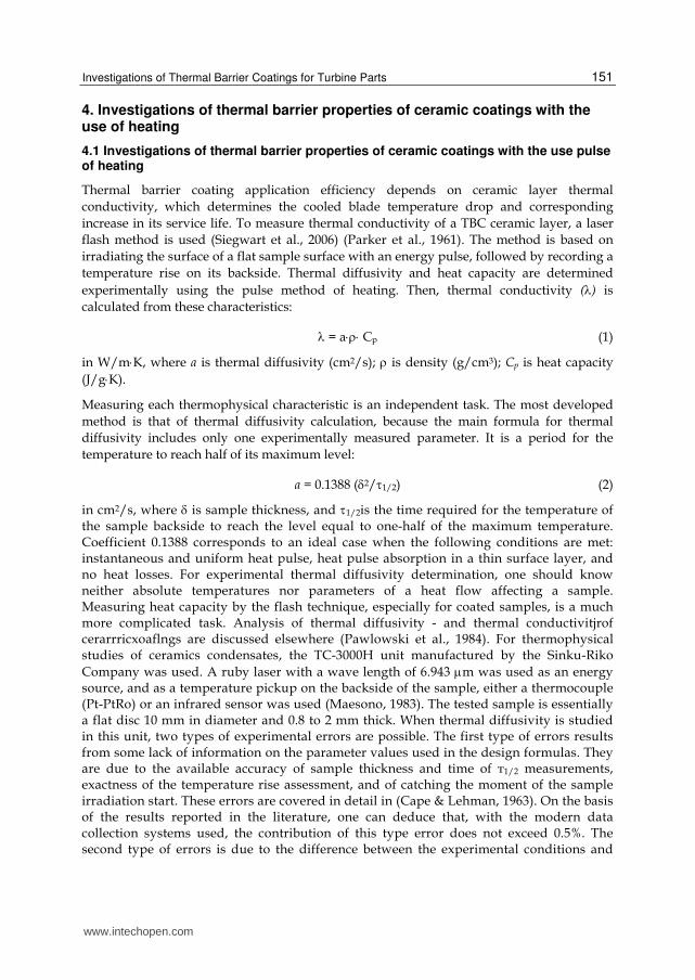
The most effective protection of a detail material against a thermal flow occurs in case of use ofelectron beam method for depositing of ceramic coatings ZrO2 (Tamarin & Kachanov, 2008). With the help of the specified method the ceramic coating of column structure on a surface of a metal sublayer (heat resisting coating) of working turbine blade is formed. The specified ceramic barrier coating is generated as columns (Fig. 26), are directed perpendicularly surface on which it is deposited. The columns of the ceramic coating possess low heat conductivity and provides the required durability at thermal cycles. The strength characteristics of ceramics are very low.
Fig. 26. Columnar thermal barrier ceramic coating (EB technique)
www.intechopen.com
Ceramic Coatings – Applications in Engineering
156
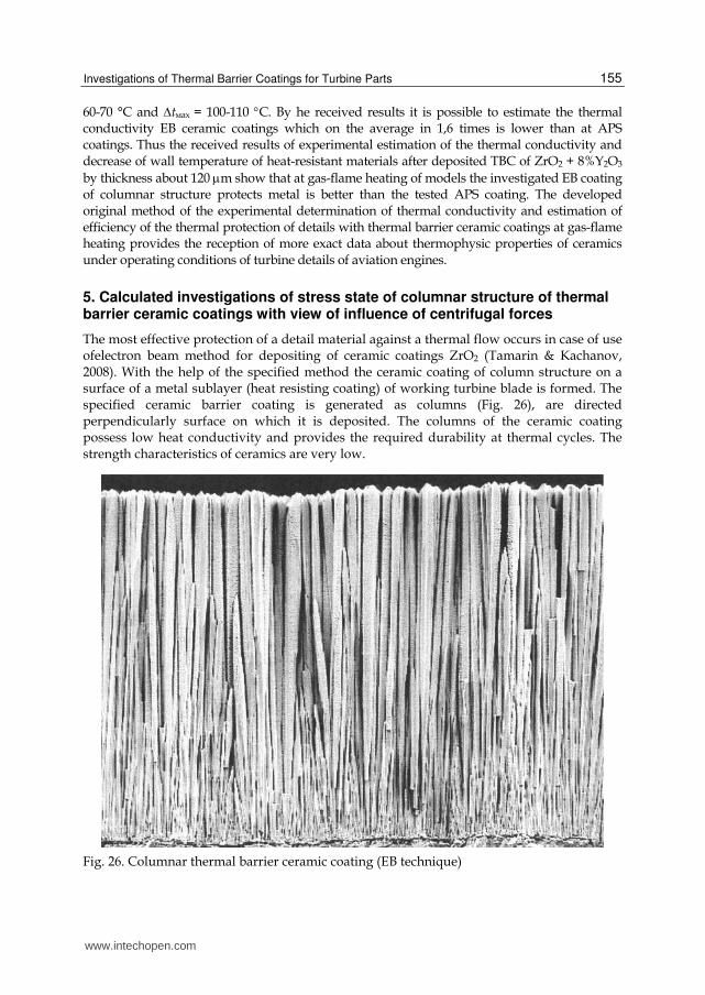
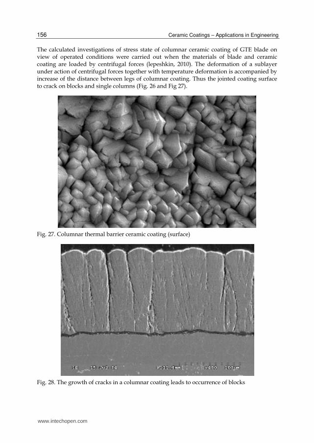
The calculated investigations of stress state of columnar ceramic coating of GTE blade on view of operated conditions were carried out when the materials of blade and ceramic coating are loaded by centrifugal forces (lepeshkin, 2010). The deformation of a sublayer under action of centrifugal forces together with temperature deformation is accompanied by increase of the distance between legs of columnar coating. Thus the jointed coating surface to crack on blocks and single columns (Fig. 26 and Fig 27).
Fig. 27. Columnar thermal barrier ceramic coating (surface)
Fig. 28. The growth of cracks in a columnar coating leads to occurrence of blocks
www.intechopen.com
Investigations of Thermal Barrier Coatings for Turbine Parts
157
Fig. 29. The top part of a columnar coating
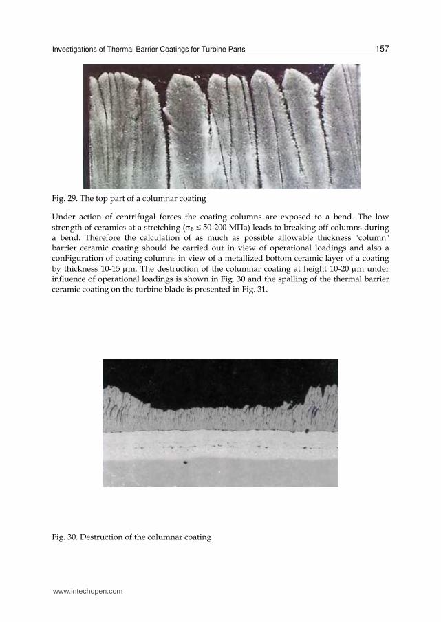
Under action of centrifugal forces the coating columns are exposed to a bend. The low
strength of ceramics at a stretching (В ≤ 50-200 М》а) leads to breaking off columns during a bend. Therefore the calculation of as much as possible allowable thickness "column" barrier ceramic coating should be carried out in view of operational loadings and also a conFiguration of coating columns in view of a metallized bottom ceramic layer of a coating
by thickness 10-15 m. The destruction of the columnar coating at height 10-20 m under influence of operational loadings is shown in Fig. 30 and the spalling of the thermal barrier ceramic coating on the turbine blade is presented in Fig. 31.
Fig. 30. Destruction of the columnar coating
www.intechopen.com

Ceramic Coatings – Applications in Engineering
158
Fig. 31. Spalling of the thermal barrier ceramic coating on the turbine blade
The analytical calculations of stress state of columns of a ceramic coаting of turbine blade were carried out under following conditions: frequency of rotation - 10000 r.p.m, radius - 400 mm
from an axis of rotation, density of a coating - 4450 kg/m3, parameters of columns: d1 = 0,5 m
- diameter of the basis of a column, d2 = 0,5÷5,0 m - diameter of the top part of a column, l - height of a column (thickness of a coating). Two calculated cases were considered (Lepeshkin & Vaganov, 2010). In the first case the stress state of a single column was considered with fastening his leg in cantilewer. In the second case the calculation of stress state of a column in the block was carried out at fastening his leg in the basis of the block and his top part in a continuous surface of the block in view of a hypothesis of plane-parallel movement. The positions of the given hypothesis consist of the following. The top part of the block of a coating is formed by connection of the top parts of columns and represents a continuous surface. The roof of coating block starts to move in parallel the basis of the block under influence of centrifugal forces on the block. In view of the specified conditions the stress state of a column in the block in a field of action of centrifugal forces is calculated. The calculated circuits for determination of the stress state of columns of a ceramic coating are resulted in Fig. 32. From Fig. 26 follows that columns have the cone form that also is shown in circuits in Fig. 32.
Fig. 32. Calculated schemes of determination of a stress state: 1 - single columns; 2 - columns in blocks; d1 - diameter of the basis of a column, d2 - diameter of the top part of a column,
www.intechopen.com
Investigations of Thermal Barrier Coatings for Turbine Parts
159
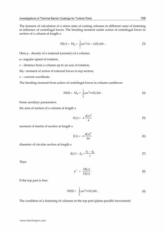
The features of calculation of a stress state of coating columns in different cases of fastening at influence of centrifugal forces. The bending moment under action of centrifugal forces in section of a column at length x:
2( ) ( - ) ( )l
B
x
M x M r v x S v dv , (3)
Here - density of a material (ceramic) of a column,
- angular speed of rotation,
r – distance from a column up to an axis of rotation,
MB - moment of action of external forces in top section,
v – current coordinate.
The bending moment from action of centrifugal forces in column cantilewer
2
0
0( ) ( )l
BM M rvS v dv . (4)
Some auxiliary parameters:
the area of section of a column at length x
2
4
( )( )
d xS x (5)
moment of inertia of section at length x
4
64
( )( )
d xJ x (6)
diameter of circular section at length x
2 0
0( )
d dd x d
l
(7)
Then
( )
'' ( )
M xy
EJ x . (8)
If the top part is free:
2
0
0( ) ( )l
M rvS v dv . (9)
The condition of a fastening of columns in the top part (plane-parallel movement)
www.intechopen.com
Ceramic Coatings – Applications in Engineering
160
2 0
0( )
d dd x d
l
. (10)
0'( ) y l (11)
As y‘(0) = 0 (rigid fastening in the basis), then
0
0 0''( ) '( ) '( )l
y v dv y l y (12)
Hence, the condition for a moment
0
( )0
( )
lM v dv
EJ v . (13)
Substituting in (10) the formula (1) we receive the moment of action of external forces in the top section of a column:
2
2
4
0
4
0
( ) ( )
( ) - '
( )
l
lv
B l
u v S u du
rd v
Mdv
d v
(14)
Thus, it is known M(x):
2
4
4
0
l
l2 v
l20
lx
( ) ( )
r( )
M(x) - r(v-x)S(v)dv.dv
( )
u v S u du
dvd v
d v
(15)
Knowing M(x) is possible to find the maximal stretching stress in section of a column:
2
max
( ) ( )( )
( )
M x d xx
J x (16)
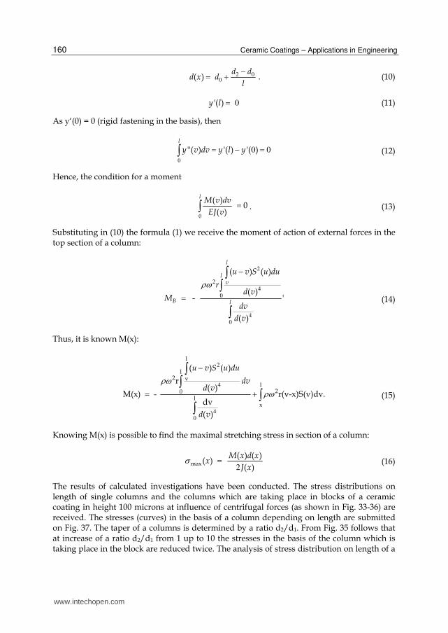
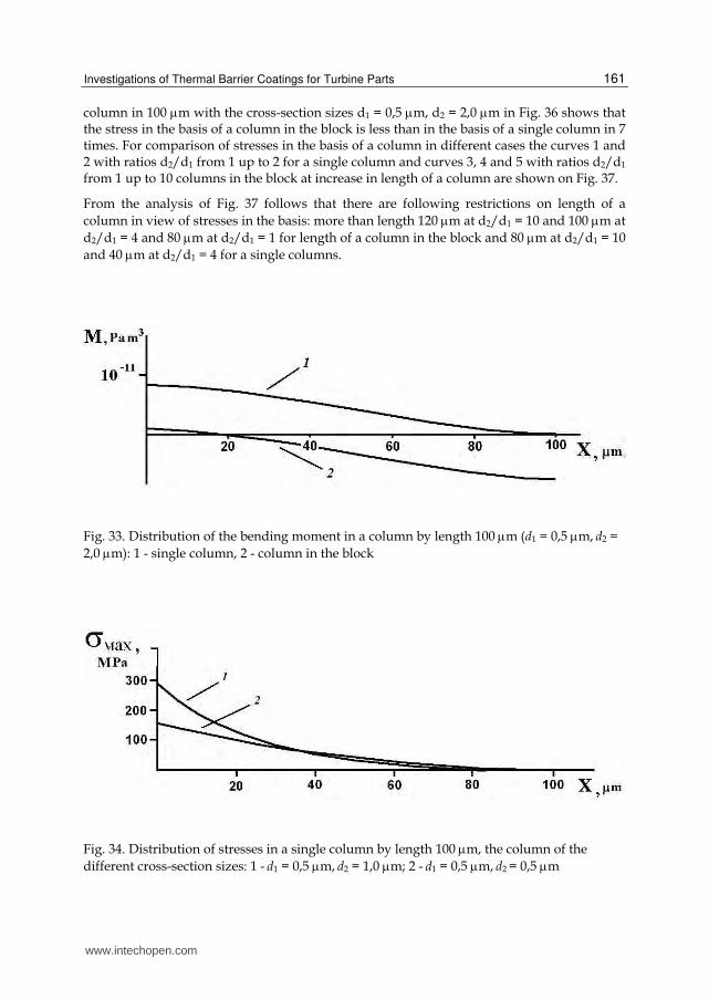
The results of calculated investigations have been conducted. The stress distributions on length of single columns and the columns which are taking place in blocks of a ceramic coating in height 100 microns at influence of centrifugal forces (as shown in Fig. 33-36) are received. The stresses (curves) in the basis of a column depending on length are submitted on Fig. 37. The taper of a columns is determined by a ratio d2/d1. From Fig. 35 follows that at increase of a ratio d2/d1 from 1 up to 10 the stresses in the basis of the column which is taking place in the block are reduced twice. The analysis of stress distribution on length of a
www.intechopen.com
Investigations of Thermal Barrier Coatings for Turbine Parts
161
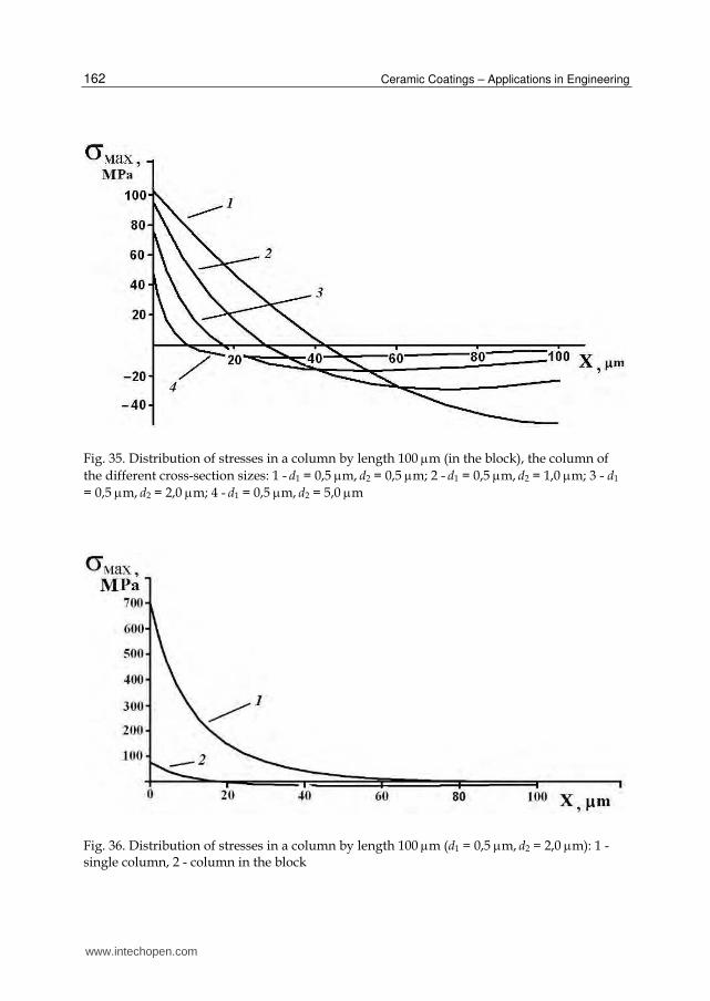
column in 100 m with the cross-section sizes d1 = 0,5 m, d2 = 2,0 m in Fig. 36 shows that the stress in the basis of a column in the block is less than in the basis of a single column in 7 times. For comparison of stresses in the basis of a column in different cases the curves 1 and 2 with ratios d2/d1 from 1 up to 2 for a single column and curves 3, 4 and 5 with ratios d2/d1
from 1 up to 10 columns in the block at increase in length of a column are shown on Fig. 37.
From the analysis of Fig. 37 follows that there are following restrictions on length of a
column in view of stresses in the basis: more than length 120 m at d2/d1 = 10 and 100 m at
d2/d1 = 4 and 80 m at d2/d1 = 1 for length of a column in the block and 80 m at d2/d1 = 10
and 40 m at d2/d1 = 4 for a single columns.
Fig. 33. Distribution of the bending moment in a column by length 100 m (d1 = 0,5 m, d2 =
2,0 m): 1 - single column, 2 - column in the block
Fig. 34. Distribution of stresses in a single column by length 100 m, the column of the
different cross-section sizes: 1 - d1 = 0,5 m, d2 = 1,0 m; 2 - d1 = 0,5 m, d2 = 0,5 m
www.intechopen.com
Ceramic Coatings – Applications in Engineering
162
Fig. 35. Distribution of stresses in a column by length 100 m (in the block), the column of
the different cross-section sizes: 1 - d1 = 0,5 m, d2 = 0,5 m; 2 - d1 = 0,5 m, d2 = 1,0 m; 3 - d1
= 0,5 m, d2 = 2,0 m; 4 - d1 = 0,5 m, d2 = 5,0 m
Fig. 36. Distribution of stresses in a column by length 100 m (d1 = 0,5 m, d2 = 2,0 m): 1 - single column, 2 - column in the block
www.intechopen.com
Investigations of Thermal Barrier Coatings for Turbine Parts
163
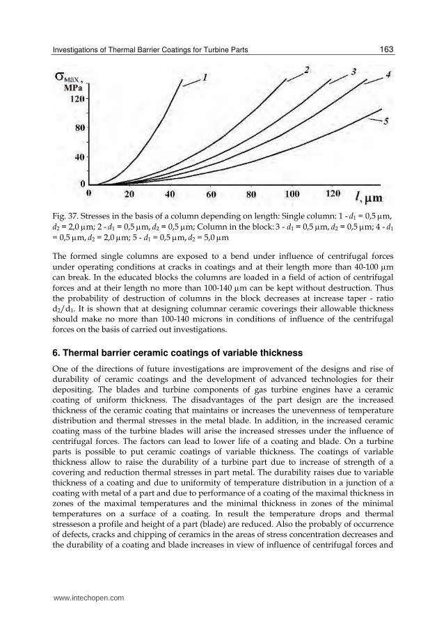
Fig. 37. Stresses in the basis of a column depending on length: Single column: 1 - d1 = 0,5 m, d2 = 2,0 m; 2 - d1 = 0,5 m, d2 = 0,5 m; Column in the block: 3 - d1 = 0,5 m, d2 = 0,5 m; 4 - d1
= 0,5 m, d2 = 2,0 m; 5 - d1 = 0,5 m, d2 = 5,0 m
The formed single columns are exposed to a bend under influence of centrifugal forces
under operating conditions at cracks in coatings and at their length more than 40-100 m can break. In the educated blocks the columns are loaded in a field of action of centrifugal
forces and at their length no more than 100-140 m can be kept without destruction. Thus the probability of destruction of columns in the block decreases at increase taper - ratio d2/d1. It is shown that at designing columnar ceramic coverings their allowable thickness should make no more than 100-140 microns in conditions of influence of the centrifugal forces on the basis of carried out investigations.
6. Thermal barrier ceramic coatings of variable thickness
One of the directions of future investigations are improvement of the designs and rise of durability of ceramic coatings and the development of advanced technologies for their depositing. The blades and turbine components of gas turbine engines have a ceramic coating of uniform thickness. The disadvantages of the part design are the increased thickness of the ceramic coating that maintains or increases the unevenness of temperature distribution and thermal stresses in the metal blade. In addition, in the increased ceramic coating mass of the turbine blades will arise the increased stresses under the influence of centrifugal forces. The factors can lead to lower life of a coating and blade. On a turbine parts is possible to put ceramic coatings of variable thickness. The coatings of variable thickness allow to raise the durability of a turbine part due to increase of strength of a covering and reduction thermal stresses in part metal. The durability raises due to variable thickness of a coating and due to uniformity of temperature distribution in a junction of a coating with metal of a part and due to performance of a coating of the maximal thickness in zones of the maximal temperatures and the minimal thickness in zones of the minimal temperatures on a surface of a coating. In result the temperature drops and thermal stresseson a profile and height of a part (blade) are reduced. Also the probably of occurrence of defects, cracks and chipping of ceramics in the areas of stress concentration decreases and the durability of a coating and blade increases in view of influence of centrifugal forces and
www.intechopen.com
Ceramic Coatings – Applications in Engineering
164
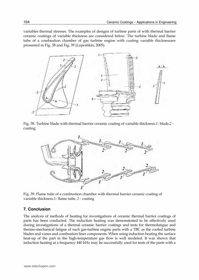
variables thermal stresses. The examples of designs of turbine parts of with thermal barrier ceramic coatings of variable thickness are considered below. The turbine blade and flame tube of a combustion chamber of gas turbine engine with coating variable thicknessare presented in Fig. 38 and Fig. 39 (Lepeshkin, 2005).
Fig. 38. Turbine blade with thermal barrier ceramic coating of variable thickness:1- blade,2 - coating
Fig. 39. Flame tube of a combustion chamber with thermal barrier ceramic coating of variable thickness:1- flame tube, 2 - coating
7. Conclusion
The analysis of methods of heating for investigations of ceramic thermal barrier coatings of parts has been conducted. The induction heating was demonstrated to be effectively used during investigations of a thermal ceramic barrier coatings and tests for thermofatigue and thermo-mechanical fatigue of such gas-turbine engine parts with a TBC as the cooled turbine blades and vanes and combustion liner components. When using induction heating the surface heat-up of the part in the high-temperature gas flow is well modeled. It was shown that induction heating at a frequency 440 kHz may be successfully used for tests of the parts with a
www.intechopen.com
Investigations of Thermal Barrier Coatings for Turbine Parts
165
TBC. It was experimentally shown that when using such a heating method, the temperature of the outer ceramic coating surface exceeds the temperature of the metallic bond coat by 50-70°C. Thus, a design-experiment method of high-frequency induction heating and thermophysical measurements in thermal cycling tests of blades and other cooled parts with a TBC has been developed taking into account the electrophysical and thermophysical properties of their materials. The results of thermophysical measurements, design-experiment studies of the nonstationary thermal state of the parts with coatings with the use of a thermal vision system, and thermal cycling tests of blades and models of flame tubes with thermal barrier ceramic coatings are presented. The generalized dependence of the temperature gradient across the ceramic coating thickness on the frequency of the electric current was obtained using multivariant calculations. The test rig with induction heating at a frequency 440 kHz was used also for making the comparison evaluation of the influence of various thermal ceramic barrier coatings (APS and EB techniques) on thermocyclic strength of the parts with a TBC (to select material and coating for the part and mature the repair technology). Gas-flame heating is considered to be preferable when investigating the gas-turbine engine parts with a TBC for thermofatigue in the special cases when both the convective and radiant components of thermal flow are of great importance. The small-size rig with gas-flame flow made it possible to conduct the comparison investigations with the purpose of evaluating the efficiency of thermal protection of the ceramic deposited thermal barrier coatings on APS and EB techniques. The developed design-experiment method was introduced in bench tests of turbine blades of gas turbine engines. The use of the developed method for high-frequency induction heating in thermal cycling tests of blades and models with thermal barrier ceramic coatings made it possible to reduce the duration of tests and their cost and to obtain the exper-imental evaluation of the service life of ceramic coatings with due regard for their nonstationary thermal and thermostressed states. The results of successful tests were used in operation of aircraft engines. At designing columnar ceramic coverings it is necessary to consider that their allowable thickness depending on conditions of influence of the centrifugal forces on the basis of carried out investigations. The further investigations will be carried out in the following directions: comparison of the results of the evaluations of the thermal cyclic fatigue life of the cooled parts during gas and high-frequency induction heating, improvement of the technique developed for determining the thermal conductivity of ceramic coatings deposited by the electron-beam technique and design of new types of coatings.
8. Acknowledgment
This work has been performed at CIAM. I is very thankful to Dr. N.G. Bychkov for his help in carrying out of the investigations of a thermal ceramic barrier coatings.
9. References
Stringer, J.; Streiff, R.; Krutenat, R. & Gaillet, M. (1989) The Reactive Element Effect in High-Temperature Corrosion, High Temperature Corrosion. No.2, pp. 129-137. Elsevier Science Publishers
Malashenko, I.S.; Vashchilo, N.P.; Belotserkovsky, V.A. & Yakovchuk, K.Y. (1997) Effect of Yttrium on Functional Characteristics of Vacuum Condensates and Protective Coatings MCrAlY and MCrAlY/ZrO2-8%Y2O3 at Thermocyclic Loading, Adv. Spec. Electrometali, Vol.1, pp. 24-33
Miller, R, A.; Garlick, R.G. & Smialek, J.L. (1983). Phase Distribution in Plasma-Sprayed Zirconia-Yttria. Am. Ceram. Soc. Bull., Vol.63, No.12, pp. 1355-1358
www.intechopen.com
Ceramic Coatings – Applications in Engineering
166
Ingel, R.P.; Lewis, D.; Bender, B.A. & Rice, R.W. (1984). Physical, Microstructural and Thermomechanical Properties of ZrO2 Single Crystals, Advances in Ceramics, Vol.12, pp. 408-414, American Ceramics Society, Inc.
Stecura, S. (1986). Optimization of the Ni-Cr-Al-Y/ZrO2-Y2O3 Thermal Barrier System, Adv.Ceram. Mater., Vol.1, pp. 68-76
Ruckle, D.L. & Duvall, D.S. (1984). Quench Cracked Ceramic Thermal Barrier Coatings, U.S. Patent 4457948, August 3, 1984
Strangman, Т.Е. (1982) Columnar Grain Thermal Barrier Coatings, U.S. Patent 4321311, March 23, 1982
Schulz, U.; Fritscher, K.; Ratzer-Scheibe, H.J., et al. (1997). Thermocyclic Behavior of Microstructurally Modified EB-PVD Thermal Barrier Coatings, High Temperature Corrosion, pp. 957-964, No.4
Parker, W.J.; Jenkins, R.J.;Bulter, C.P. & Abbott, G.L. (1961). Flash Method of Determining Thermal Diffusivity, Heat Capacity and Thermal Conductivity, J. Appl. Phys., pp. 1679-1684, Vol.32, No.9
Pawlowski, L.; Lombard, D.; Mahlia, A. et al. (1984). Thermal Diffusivity of Arc Plasma Sprayed irconia Coatings, High Temp. High Press., pp. 347-359, Vol.16
Maesono, A. (1983). Measurement of Thermal Constants by Laser Flash Method, SinkuRiko Co. LTD, April, 1983
Cape, A. & Lehman, G.W. (1963). Temperatureand Finite-Pulse Time Effect in the Flash Method for Measuring Thermal Diffusivity, J. Appl. Phys., p 1909-1913, Vol.34, No.7
Clark, L.M. & Taylor, R.E. (1975). Radiation Loss in the Flash Method for Thermal Diffusiv-ity, Appl. Phys., pp. 714-719, Vol.46, No.2
Nicholls, J.R.; Lawson, KJ.; Johnston, A. & Rickerby, D.S. (2001). Low Thermal Conductivity EB-PVD Thermal Barrier Coatings, High Temperature Corrosion, Ed., Trans Tech Publication, pp. 595-606, No.5
Lawson, K.J.; Nicholls, J.R. & Rickerby, D.S. (1996). The Effect of Coating Thickness on the Thermal Conductivity of CVD and PVD Coatings, Fourth International Conf. on Advances in Surface Engineering, Newcastle, U.K.
Kuvaldin, A.B. & Lepeshkin, A.R. (2006). High speed Regimes of Heating and Thermal stresses in Articles, NGTU, 286 р., ISBN 5-7782-0626-7, Novosibirsk
Lepeshkin, A.R.; Bychkov, N.G. & Perchin, A.V. (2005). Method of Test Parts with a Thermal barrier coating for durability, R.U. Patent 2259548, July 27, 2005
Bychkov, N.G.; Nozhnitsky, Y.A.; Perchin, A.V. et al. (2008). Investigations of Thermomechanical Fatigue for Optimization of Design and Production Process Solutions for Gas-Turbine Engine Parts, International Journal Fatique, No.30
Tamarin, Yu.A. & Kachanov, E.B. (2008). Properties of the Thermal Protective Coatings Rendered by Electron Beam Technology (New Technological Processes and Reliability of Gas Turbines Engines), CIAM, pp. 125-143, issue 7,Moscow
Rubashev, M.A.; Presnov, V.A. & Rotner, Yu.M. (1980) Thermal Dielectrics and Their Junction in New Technologies, Atomizdat, Moscow
Lepeshkin, A.R. & Vaganov, P.A. (2010). The Calculation of Stressed State of the Cone-Columnar Structure of the Thermal Barrier Ceramic Coatings of GTE Blades under Service Loads, Russian Conference “New materials and technology“, MATI, p. 57, Moscow
Lepeshkin, A.R.; Bychkov, N.G. & Perchin, A.V. (2005). Turbine Blade, R.U. Patent 2259481, July 27, 2005
Lepeshkin, A.R.; Bychkov, N.G. & Perchin, A.V. (2005).Flame Tube of a Combustion Chamber, R.U. Patent 2260156, September 10, 2005
www.intechopen.com
Ceramic Coatings - Applications in EngineeringEdited by Prof. Feng Shi
ISBN 978-953-51-0083-6Hard cover, 286 pagesPublisher InTechPublished online 24, February, 2012Published in print edition February, 2012
InTech EuropeUniversity Campus STeP Ri Slavka Krautzeka 83/A 51000 Rijeka, Croatia Phone: +385 (51) 770 447 Fax: +385 (51) 686 166www.intechopen.com
InTech ChinaUnit 405, Office Block, Hotel Equatorial Shanghai No.65, Yan An Road (West), Shanghai, 200040, China
Phone: +86-21-62489820 Fax: +86-21-62489821
The main target of this book is to state the latest advancement in ceramic coatings technology in variousindustrial fields. The book includes topics related to the applications of ceramic coating covers in enginnering,including fabrication route (electrophoretic deposition and physical deposition) and applications in turbineparts, internal combustion engine, pigment, foundry, etc.
How to referenceIn order to correctly reference this scholarly work, feel free to copy and paste the following:
Alexandr Lepeshkin (2012). Investigations of Thermal Barrier Coatings for Turbine Parts, Ceramic Coatings -Applications in Engineering, Prof. Feng Shi (Ed.), ISBN: 978-953-51-0083-6, InTech, Available from:http://www.intechopen.com/books/ceramic-coatings-applications-in-engineering/investigations-of-thermal-barrier-coatings-for-turbine-parts