Embed Size (px)
Citation preview
www.resourcesandenergy.nsw.gov.au/safety
Investigation report
Investigation into the serious injury of a mine worker at the Perilya Broken Hill Southern Operations Mine, Broken Hill, NSW on 8 June 2012.
Report prepared by the NSW Mine Safety Investigation Unit
23 May 2014
Published by NSW Department of Trade and Investment, Regional Infrastructure and Services
Investigation report to the Secretary NSW Trade & Investment
Investigation into the serious injury of a mine worker at Perilya Broken Hill Southern Operations Mine, Broken Hill, NSW on 8 June 2012.
Report date: 23 May 2014
Author:
Mine Safety Investigation Unit
www.trade.nsw.gov.au
© State of New South Wales through the Department of Trade and Investment, Regional Infrastructure and Services 2014.
This publication is copyright. You may download, display, print and reproduce this material in an unaltered form only (retaining this notice) for your personal use or for non-commercial use within your organisation. To copy, adapt, publish, distribute or commercialise any of this publication you will need to seek permission from the NSW Department of Trade and Investment, Regional Infrastructure and Services.
Disclaimer: The information contained in this publication is based on knowledge and understanding at the time of writing (May 2014). However, because of advances in knowledge, users are reminded of the need to ensure that information upon which they rely is up to date and to check currency of the information with the appropriate officer of the NSW Department of Trade and Investment, Regional Infrastructure and Services or the user’s independent advisor.
Investigation report
i NSW Trade & Investment, May 2014
Executive summary Incident overview At 9.47 am on 8 June 2012, a 51-year-old mine worker (the rigger) was seriously injured when he fell from an elevated loader bucket of a Caterpillar front end loader at the Perilya Broken Hill Southern Operations Mine. The incident occurred about 1140 metres underground at the southern ore weighing and loading flask (weigh flask) on the 26 sub level of the NBHC Haulage Shaft.
The rigger was using the loader bucket as an elevated work platform and it was suspended over the shaft. While attempting to secure a large weight to the weigh flask, the rigger fell about 14 metres to the base of the shaft. There was a second worker in the loader bucket at the time of the incident. The second worker was not injured.
An unrestrained steel weight basket containing three weight blocks (combined weight of 9.8 tonne) also fell from the loader bucket and became lodged on steel work in the shaft. One of the weight blocks, weighing 3 tonnes fell from the basket to the base of the shaft.
The rigger’s fall arrest system did not arrest his fall.1
The rigger’s right leg was severed during the fall. He also suffered three spinal fractures, seven broken ribs and a lacerated liver.
The rigger was rescued by mines rescue personnel, evacuated from the mine and provided emergency medical treatment.
The purpose of the task The workers were attempting to secure a 9.8 tonne weight basket to the base of the weigh flask to enable calibration of the electronic 55 tonne tension load cell system (load cell) attached to the top of the weigh flask.
The weigh flask is one of two flasks used to measure and load predetermined volumes of ore into a haulage skip. The skip is lifted by a wire winding rope via a vertical hoist winder system to the surface of the mine.
A load cell supplier originally provided calibrated load cells to the mine. The load cell system was altered by mine electricians in May, 2012. These changes resulted in ore haulage discrepancies. The mine subsequently determined that the load cell system needed to be recalibrated by hanging a known weight to the base of the weigh flask.
Investigation observations The investigation identified a range of factors that contributed to the incident, summarised below.
Safe work practices
• This was the first time the mine workers had undertaken the task.
• The system of work envisaged by mine supervisors was not the system of work used by the mine workers to undertake the task.
• The task documentation created by mine supervisors did not specifically identify how the work task was to be performed.
1 Working at Heights Association – Glossary of terms (issued 22/09/11) Fall-arrest System – An assembly of interconnected
components comprising a full body harness connected to an anchorage point or anchorage system either directly or by means of a lanyard or pole strap, and whose purpose is to arrest a fall in accordance with the principles and requirements of ASNZS 1891.4. (AS / NZS 1891.4 Clause 1.4.5).
Investigation report
ii NSW Trade & Investment, May 2014
• Verbal discussions had taken place between supervisors and the rigger before the incident but safe work procedures were not documented.
• The mine did not permit the use of the loader bucket as an elevated work platform. However, this prohibition was not specifically documented in mine procedures.
Fit-for-purpose equipment
• The loader bucket was not designed to be used as an elevated work platform.
• The loader bucket was not designed to be used for the purpose of lifting steel weight baskets or people.
• The fall arrest system used did not restrain the rigger’s fall.
• There was no energy absorbing device incorporated in the rigger’s fall arrest system.
• The method that the rigger used to connect the lanyard to the loader bucket was not recommended in the published guidelines in AS/NZS 1891.4:2009.
• The fall arrest system equipment that the two mine workers used had not been stored and inspected under the mine’s fall arrest equipment storage and inspection system.
• Several components of the fall arrest equipment that the two mine workers used would not have passed a ‘fit for purpose’ inspection.
Competent people
• Supervisors involved in the task planning did not document how the task was to be performed.
• Task assessment documentation created by the rigger was inadequate and was not reviewed by the supervisors who had planned the task.
• There was no supervisory oversight of the task being undertaken.
• The rigger held certificates of competency as a Dogman (Class 2) and Rigger (Class 1). The rigger’s working at heights competencies were obtained following a one day training course completed in 2007 and recognition of prior learning in 2011.
Foreseeable risk The mine had documented risk assessments in place that identified the foreseeable risk of people falling down a shaft when conducting tasks in and around shafts. To control the identified risk of falling down a shaft, fit-for-purpose fall arrest equipment was required to be worn for various tasks undertaken in and around the shaft.
According to the mine, the use of a loader bucket as an elevated work platform was prohibited at the mine. However, this prohibition was not specifically documented in any of the mine’s safety management plan records or training documents.
Remedial safety measures After the incident the mine took the following remedial actions:
• An accredited height safety equipment inspector inspected all fall arrest system equipment at the mine.
• Fall arrest equipment that did not pass inspection was removed and tagged out of service.
Investigation report
iii NSW Trade & Investment, May 2014
• The mine introduced an inspection program of all height safety equipment on a quarterly basis.
• The mine revised and formalised a management plan for height safety equipment.
• All new workers were inducted and given clear instructions that working at heights in anything other than a ‘certified man riding basket’ was not permitted.
• Mine worker induction documents were amended to prohibit operators from working out of a loader bucket and described the height safety equipment inspection and testing process and coloured tag expiry system.
• Mine Rescue Officers were trained and accredited to inspect and maintain height safety equipment.
• All height safety equipment was required to be stored in the safety store and issued on a shift by shift basis. A trained and accredited Mines Rescue Officer was to inspect equipment when it was returned to the store at the end of the shift.
• Any defective equipment was taken out of service until it was inspected by an external accredited height safety equipment inspector during the next quarterly visit to site.
• New harnesses and lanyards came into the system only after they were inspected, tagged and marked with a unique identification and added to the equipment register.
• Every item in the height safety equipment register was inspected and certified as ‘fit for purpose’ on a quarterly basis.
• All height safety equipment in use was required to display the nominated colour tag to verify that it was ‘fit for use’.
• The mine communicated the incident to the workforce and provided information about the injured workers’ conditions and the impact on the mine’s operation.
• Safety meetings were held where a PowerPoint presentation was delivered to all workers and included the department’s Safety Alert (SA 12-03) Worker loses leg in fall.
• The Perilya Mine Health and Safety Committee members were included in the information meetings and two committee members were involved in the incident investigation team.
Recommendations The preliminary findings of the investigation and recommendations were published by the department in Safety Alert (SA12-03) Worker loses leg in fall on 27 June 2012. The Safety Alert made the following recommendations to the NSW mining industry:
Review current practices and:
1. Prohibit people from working in the bucket of a front end loader or other similar apparatus.
2. When working at heights:
• Ensure compliance with the provisions of the Work Health and Safety Regulation 2011 (WHSR) Part 4.4 Falls.
• Consider the Model Code of Practice – Managing the Risk of Falls at Workplaces. See www.safeworkaustralia.gov.au
Investigation report
iv NSW Trade & Investment, May 2014
• Include in ‘fall from height’ protocols provision for training and instruction in fit for purpose equipment to ensure it is properly stored, tested, maintained and discarded where appropriate.
3. When lifting people:
• Ensure compliance with provisions of clause 219 and clause 220 of the WHSR, in particular that people are lifted or suspended in a work box.
• Use fit-for-purpose elevated work platforms with consideration to AS 2550, AS1418.10 and the recommendation in Safety Alert SA08-09 Workers injured on work platform attached to load haul dump. Note: elevated work platforms manufactured after 1 December 2003 must be design registered. See Schedule 5 of the WHSR.
4. When meeting your obligations under Part 3.1 WHSR, ensure:
• Risk control measures are implemented in accordance with the hierarchy of controls.
• Safe systems of work are:
o developed through competent people o developed through effective consultation o effectively communicated o consistent with established methodologies – refer to Risk Management
Standard AS/NZS ISO 3100 5. In accordance with clause 37 and clause 38 of the WHSR, ensure competent
people are involved in reviewing the adequacy and maintenance of risk controls.
Investigation Report
v NSW Trade & Investment, May 2014
Contents
Executive summary ........................................................................................................ i Incident overview ...................................................................................................................... i
The purpose of the task ............................................................................................................ i
Investigation observations ......................................................................................................... i
Foreseeable risk ....................................................................................................................... ii
Remedial safety measures ........................................................................................................ ii
Recommendations ................................................................................................................... iii
1. Purpose of report ....................................................................................................... 1
2. Investigation parameters ........................................................................................... 1
The department’s Investigation Unit ......................................................................................... 1
Investigation scope .................................................................................................................. 1
Legislative authority to investigate ........................................................................................... 1
The department’s response to the incident .............................................................................. 2
3. The Perilya Broken Hill Southern Mine .................................................................... 3
The mining lease ..................................................................................................................... 3
The mine .................................................................................................................................. 3
4. The companies involved ........................................................................................... 4
Perilya Limited ......................................................................................................................... 4
Perilya Broken Hill Pty Ltd ........................................................................................................ 4
Consolidated Mining and Civil Pty Ltd ...................................................................................... 4
5. The incident site ......................................................................................................... 4
NBHC haulage shaft ................................................................................................................ 4
6. Circumstances of the incident .................................................................................. 6
Events leading up to the incident ............................................................................................. 6
The planned work task ............................................................................................................. 7
The use of a 10.2 tonne payload front end loader for the task .................................................. 7
Creation of task procedure documentation ............................................................................... 8
The JSA created on 8 June 2012 ............................................................................................. 8
The ‘Take Time Take Charge’ document created on 8 June 2012 ........................................... 9
Task preparation conducted at the work site ............................................................................ 9
The proposed rigging procedure for the task ............................................................................ 9
The actual rigging procedure used for the task ...................................................................... 10
The worker’s fall from the loader bucket ................................................................................. 11
Investigation report
vi NSW Trade & Investment, May 2014
The rescue of the worker ....................................................................................................... 11
Training and experience ........................................................................................................ 12
Use of the loader bucket as a work platform .......................................................................... 12
7. Post incident observations of loader functionality ............................................... 14
8. Fall arrest safety equipment - harness and lanyard .............................................. 16
Lanyard reeving method ........................................................................................................ 18
Laterally extended anchorage line reviewed at simulation testing .......................................... 19
9. Remedial actions ...................................................................................................... 21
10. Conclusion .............................................................................................................. 22
Safe work practices ................................................................................................................ 22
Fit-for-purpose equipment ...................................................................................................... 22
Competent people.................................................................................................................. 23
11. Recommendations ................................................................................................. 23
Investigation report
1 NSW Trade & Investment, May 2014
1. Purpose of report This report concerns the serious injury of a mine worker at the Perilya Broken Hill Southern Operations Mine, Broken Hill on 8 June 2012.
It documents the mining workplace incident investigation conducted by the department’s Mine Safety Investigation Unit into the cause and circumstances of the incident.
The report contains valuable information that may assist the mining industry to improve work, health and safety performance.
2. Investigation parameters The department’s Investigation Unit The Investigation Unit investigates the nature, circumstances and cause of major accidents and incidents in the NSW mining and extractives industry.
Its role is to carry out a detailed analysis of incidents and report its findings to enhance industry safety and to give effect to the department’s Enforcement Policy.
The unit is autonomous within the department and reports directly to the Secretary on all matters in relation to an investigation. It is located separately from the department’s Mine Safety Operations Inspectorate and is not involved in the activities of the inspectors, or the day-to-day inspection of mines.
Investigation scope In accordance with departmental policy, the incident resulted in an investigation by the Investigation Unit because the incident involved the serious injury of a mine worker.
The investigation was conducted under the Work Health and Safety Act 2011 (WHSA). The unit had authority to conduct an investigation into this matter because the incident occurred at a mining workplace regulated by the department.
The investigation focused on:
• identifying the cause and circumstances of the incident, • identifying whether the WHSA and Regulations have been complied with, and • identifying how similar incidents of this nature can be prevented in the future.
Legislative authority to investigate Under the WHSA, the regulator of a mining workplace or a coal workplace is the head of the department. 2 The head of the department is the Secretary.
A mining workplace is defined by the WHSA to mean a place of work to which the Mine Health and Safety Act 2004 (MHSA) applies.3 The MHSA is administered by the Minister for Resources and Energy and the department.
A mining workplace includes ‘any place where the extraction of material from land for the purpose of recovering minerals or quarry product is carried out.’4 The Perilya Broken Hill Southern Operations Mine at Broken Hill is on Consolidated Mining Lease No.8 and is a mine to which the MHSA applies.
2 WHSA section 4 (definition of ‘regulator). 3 WHSA section 4 (definition of ‘mining workplace). 4 MHSA section 6(1)(a).
Investigation report
2 NSW Trade & Investment, May 2014
The MHSA provides for the appointment of government officials5 to have oversight of mines. A person who is appointed as a government official under the MHSA is deemed to be an inspector for the purposes of the WHSA.6 An inspector has powers and functions, including the function of investigating contraventions of the WHSA.7
The Investigation Unit investigators are appointed as government officials under the MHSA and are therefore deemed to have been appointed as inspectors for the purposes of the WHSA and have the powers of an inspector under that Act in relation to mining workplaces.
The department’s response to the incident The department’s Mine Safety inspectors attended the incident scene on 8 June 2012.
As the incident resulted in a serious injury, the matter was referred to the Investigation Unit in accordance with departmental procedures.
The investigation was conducted in consultation with stakeholders. Investigation activities included:
• Incident scene analysis and photography. • Examining the operational functionality of the loader. • Examining the fall arrest equipment used in the incident and other fall arrest equipment at
the mine. • Conducting interviews to obtain information. • Issuing statutory notices to obtain information and documents. • Collating information and records from the mine.
5 MHSA section 127. 6 WHSA section 156 A (2). 7 WHSA section 160.
Investigation report
3 NSW Trade & Investment, May 2014
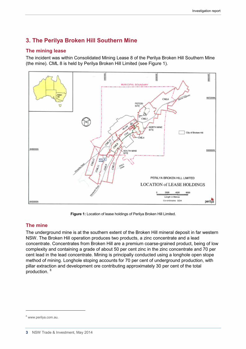
3. The Perilya Broken Hill Southern Mine The mining lease The incident was within Consolidated Mining Lease 8 of the Perilya Broken Hill Southern Mine (the mine). CML 8 is held by Perilya Broken Hill Limited (see Figure 1).
Figure 1: Location of lease holdings of Perilya Broken Hill Limited.
The mine The underground mine is at the southern extent of the Broken Hill mineral deposit in far western NSW. The Broken Hill operation produces two products, a zinc concentrate and a lead concentrate. Concentrates from Broken Hill are a premium coarse-grained product, being of low complexity and containing a grade of about 50 per cent zinc in the zinc concentrate and 70 per cent lead in the lead concentrate. Mining is principally conducted using a longhole open stope method of mining. Longhole stoping accounts for 70 per cent of underground production, with pillar extraction and development ore contributing approximately 30 per cent of the total production. 8
8 www.perilya.com.au.
Investigation report
4 NSW Trade & Investment, May 2014
4. The companies involved Perilya Limited The mine was acquired by Perilya Limited in May 2002.
Perilya Limited holds 1042 square kilometres of prospective terrain that includes the mine leases, incorporating the Southern Operations Mine, the North Mine, and the Potosi Trend, and the historic Little Broken Hill and Pinnacles areas.
Perilya Broken Hill Pty Ltd Perilya Broken Hill Pty Ltd is the nominated operator of the mine and the employer of the injured mine worker. Perilya Limited is the ultimate holding company of Perilya Broken Hill Pty Limited.
Consolidated Mining and Civil Pty Ltd Consolidated Mining and Civil Pty Ltd (CMC) was contracted by the mine operator to provide the loader and a loader operator for the work tasks associated with the incident on 8 June 2012.
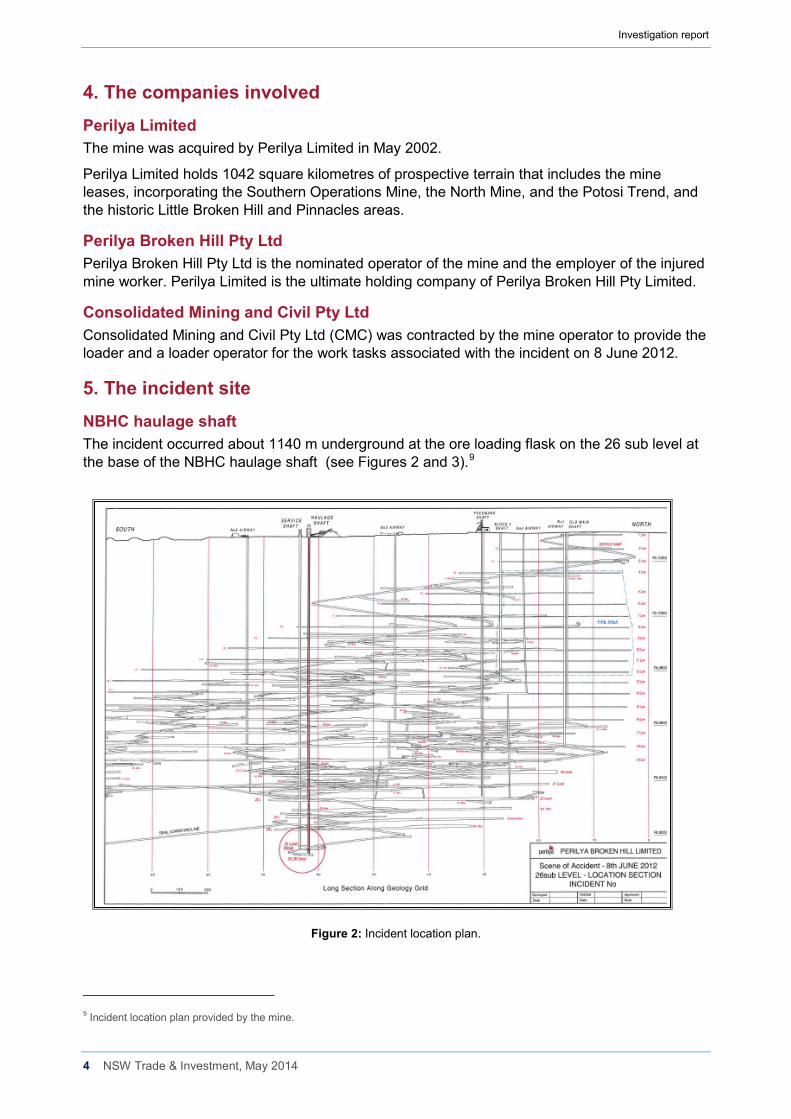
5. The incident site NBHC haulage shaft The incident occurred about 1140 m underground at the ore loading flask on the 26 sub level at the base of the NBHC haulage shaft (see Figures 2 and 3).9
Figure 2: Incident location plan.
9 Incident location plan provided by the mine.
Investigation report
5 NSW Trade & Investment, May 2014
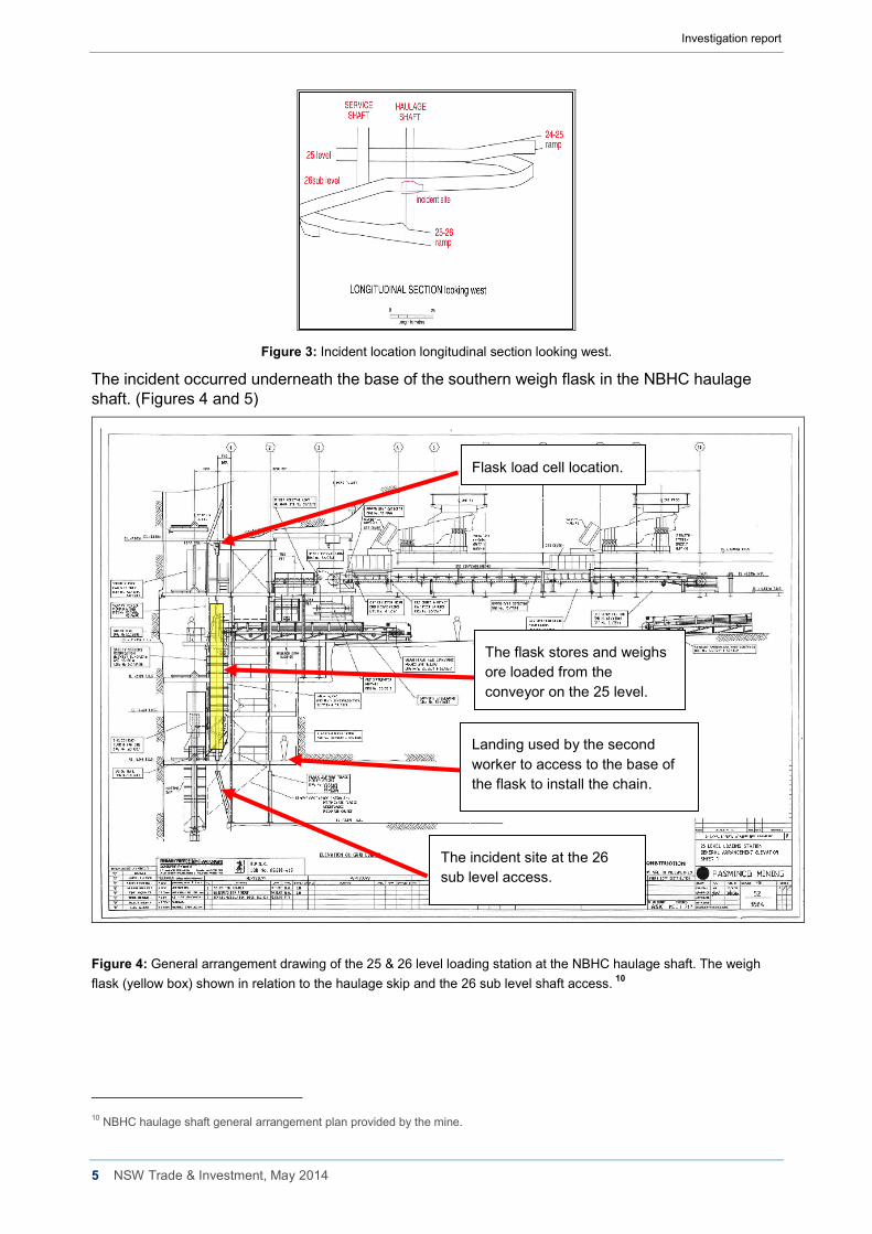
Figure 3: Incident location longitudinal section looking west.
The incident occurred underneath the base of the southern weigh flask in the NBHC haulage shaft. (Figures 4 and 5)
Figure 4: General arrangement drawing of the 25 & 26 level loading station at the NBHC haulage shaft. The weigh flask (yellow box) shown in relation to the haulage skip and the 26 sub level shaft access. 10
10 NBHC haulage shaft general arrangement plan provided by the mine.
The incident site at the 26 sub level access.
The flask stores and weighs ore loaded from the conveyor on the 25 level.
Landing used by the second worker to access to the base of the flask to install the chain.
Flask load cell location.
Investigation report
6 NSW Trade & Investment, May 2014
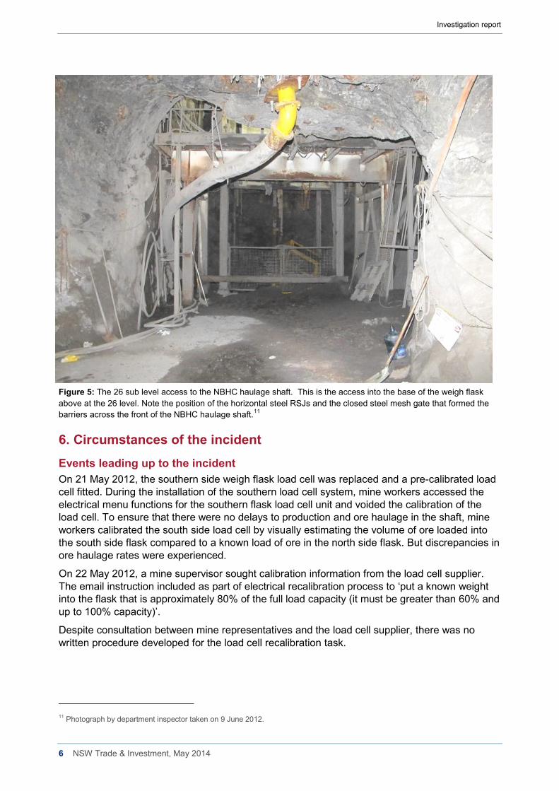
Figure 5: The 26 sub level access to the NBHC haulage shaft. This is the access into the base of the weigh flask above at the 26 level. Note the position of the horizontal steel RSJs and the closed steel mesh gate that formed the barriers across the front of the NBHC haulage shaft.11
6. Circumstances of the incident Events leading up to the incident On 21 May 2012, the southern side weigh flask load cell was replaced and a pre-calibrated load cell fitted. During the installation of the southern load cell system, mine workers accessed the electrical menu functions for the southern flask load cell unit and voided the calibration of the load cell. To ensure that there were no delays to production and ore haulage in the shaft, mine workers calibrated the south side load cell by visually estimating the volume of ore loaded into the south side flask compared to a known load of ore in the north side flask. But discrepancies in ore haulage rates were experienced.
On 22 May 2012, a mine supervisor sought calibration information from the load cell supplier. The email instruction included as part of electrical recalibration process to ‘put a known weight into the flask that is approximately 80% of the full load capacity (it must be greater than 60% and up to 100% capacity)’.
Despite consultation between mine representatives and the load cell supplier, there was no written procedure developed for the load cell recalibration task.
11 Photograph by department inspector taken on 9 June 2012.
Investigation report
7 NSW Trade & Investment, May 2014
The planned work task
On 23 May 2012, senior mine personnel informed mine supervisors that a known weight needed to be suspended from the mine’s NBHC shaft haulage flasks to recalibrate the weigh flask load cells.
Three mine supervisors inspected the NBHC shaft haulage flask work site, took measurements and photographs of the plant/equipment and discussed how the work could be undertaken from the landing at the 25 level at the base of the flask. Following this site visit, a supervisor made dimensional notations on several photographs of the work site, however there was no written work procedure documented specifying how to conduct the task.
A supervisor told investigators it was possible to remove the load cell and send it back to the load cell supplier for calibration. It was reported that it would take approximately six hours to remove the load cell and replace it with a new load cell. The mine operator did not adopt this course of action.
It was decided to suspend a known weight to the base of the weigh flask (9.8 tonnes). This involved rigging chains and slings that were adequate to suspend the designated weight below the flask.
Supervisors envisaged that the rigging components (including synthetic fibre slings, chain and rope) would be assembled on the ground. It was also envisaged that these components would be attached to the 9.8 tonne weight basket in a loader bucket. As the loader bucket was raised a worker could haul the components by hand from the landing above at the 25 level and attach them to the base of the weigh flask. Once secured it was envisaged that the loader bucket could be lowered and the 9.8 tonne weight basket would swing free of the loader bucket and would be suspended under the flask. This work process did not require a worker to be in the loader bucket. This proposed work procedure was not documented.
On 5 June 2012, a meeting was held between task planning supervisors and the rigger selected to undertake the task, in which the recalibration works were discussed. The discussions at the meeting were not documented nor were written instructions provided to the rigger about how the task was to be performed.
On 7 June 2012, the rigger received further verbal information about conducting the task from two supervisors. One supervisor told investigators that the mine worker was considered to be an experienced rigger in the shaft work group at the mine. All instructions provided to the rigger by supervisors were verbal.
Notably, the envisaged method of rigging the weight basket to the flask was not the method used when the incident occurred on 8 June 2012.
The use of a 10.2 tonne payload front end loader for the task The mine planned to use a 12.5 tonne payload front end loader to lift the weight 9.8 tonne weight basket. During the preparation for the task the 12.5 tonne payload loader was unavailable. A mine supervisor arranged for a Caterpillar 10.2 tonne payload loader and a loader operator from CMC to load the weight basket into the loader bucket on the surface of the mine. The weight basket was secured to the loader bucket with chains.
The loader operator was instructed to transport the loaded weight basket to the work site via the mine decline access roadway. This task was completed on 7 June 2012 in preparation for the recalibration task the following day.
Investigation report
8 NSW Trade & Investment, May 2014
Creation of task procedure documentation A shaft infrastructure risk assessment for shaft operations was undertaken in October 2009. The risk assessment scope of work included maintenance of shaft, services and ore pass operations.12 The risk assessment identified the foreseeable risk of ‘Falling down the shaft whilst carrying out maintenance’ and the risk was ranked as having a ‘possible likelihood’ and a ‘high risk level’.
The mine’s risk management guideline stated “All work is carried out with a risk based approach that seeks to identify and manage hazards”.
But there was no standard operating procedure (SOP) or safe work procedure (SWP) created for the task undertaken on 8 June 2012. The rigger created a job safety analysis form (JSA) before going underground, but no specific risk assessment was undertaken to develop a SWP.
The JSA created on 8 June 2012 On the morning of 8 June 2012, the shift supervisor instructed the rigger to complete a JSA in relation to the task.
The Perilya procedure for Job Safety Analysis stated: “Job safety analysis is a process where the hazards associated with each step of the job/task are identified and control measures are put in place to minimise the risk to personnel, environment and property”. 13
The rigger titled the JSA document ‘Skip Flask Weights’ and completed the document himself without assistance from any other person. The rigger wrote the JSA on the surface of the mine.
The mine’s documented JSA process required a JSA team to undertake the JSA in a team setting made up of a task supervisor and all the personnel who would be performing the task.14 This process did not occur.
The shift supervisor had returned to work on 6 June 2012 from rostered days off. During a changeover meeting he was informed that the rigger selected to undertake the recalibration task had been given instructions on how to conduct the task at the meeting on 5 June 2012.
The shift supervisor reviewed the JSA on the surface of the mine. The JSA identified five steps in the entire work process of rigging the weight basket to the flask. Below are extracts from the handwritten JSA signed by the supervisor on 8 June 2012.
• Step Number 1 o Clean area to work in,
Hazard; slips, trips, falls Controls; clean work area
• Step Number 2 o Place loader in position,
Hazard; clear line of site Control; One person to instruct loader driver
• Step Number 3
o Connect weights to bottom of flask, Hazards; Lifting equipment breakage Controls; Correct lifting equipment
12 Perilya Shaft infrastructure risk assessment dated 9/10/09 element 7.7 page 32. 13 Perilya HSE management system HSE Management system PBH procedure for JSA page 4. 14 Perilya HSE management system HSE Management system PBH procedure for JSA page 6 item 2.6.2.
Investigation report
9 NSW Trade & Investment, May 2014
• Step Number 4 o Lower loader bucket so flask takes the weight,
Hazard; Weight can swing away from the loader bucket Controls; Hold weights back with chain blocks
• Step Number 5 o Repeat job on other side
The JSA was inadequate and lacked the specific detail required for the task. Nevertheless, the shift supervisor signed the JSA without inquiring how the rigger would undertake the rigging procedure. The supervisor also signed the JSA before the other two workers involved in the task. The supervisor did not issue any instructions prohibiting the use of the loader bucket as an elevated work platform during the task. The supervisor told the rigger to start the task and not to wait for him to attend the work site. There were no approving signatories on the JSA in the required areas titled ‘Area Superintendent’ or ‘Area Manager’.
The ‘Take Time Take Charge’ document created on 8 June 2012 The same morning the rigger completed a ‘Take Time Take Charge’ pro-forma document, which the rigger titled ‘Skip Flask Weights’.
The form required a person to review, identify and control the hazards in the workplace. The form required the person to circle a ‘yes’ or ‘no’ answer to 23 questions related to hazards and circle a further 17 ‘yes’ or ‘no’ answers to questions related to planning, following the plan and any changes to the work plan.
The rigger circled ‘yes’ to all questions that asked ‘have you identified and controlled the hazards in your workplace?’ including the hazards of:
• Working at heights • All energy sources identified and unidentified
The rigger circled ‘no’ to the question that asked if the JSA could be improved and circled ‘yes’ that all personal protection equipment and safety equipment was correct.
Task preparation conducted at the work site The rigger travelled from the surface to 26 sub-level where he met the second mine worker who had been allocated to assist with the task and the CMC loader operator. The mine workers discussed the work procedure and the second worker and the loader operator signed the JSA without having input into its content or completion.
Before undertaking the task the chains tethering the weight basket into the loader bucket were removed. The workers conducted a trial lift of the weight basket without workers in the loader bucket. The loader operator lifted the untethered weight basket above the gate and into the shaft. The weight basket was lowered back to the ground without incident.
The proposed rigging procedure for the task The rigging procedure envisaged by supervisors but not documented involved hanging a 16 mm chain assembly (working load limit of 13.8 tonne including a ring and two shortening hooks) from two lugs on the base of the flask. It was intended that the 16 mm chain would be attached to the fibre slings placed around the base of the weight basket and adjusted to length on the ground before any lifting took place. Then a rope would be attached to the chain hooks and pulled upwards by a person on the landing above the loader at the same time the loader lifted the weight basket into position below the weigh flask. Once secured the loader bucket would be lowered and the weight basket would be suspended below the flask.
Investigation report
10 NSW Trade & Investment, May 2014
This rigging process did not require people to be in the loader bucket. Using this method all workers would be positioned behind fixed steel barriers to the shaft and therefore fall arrest equipment was not necessary.
The actual rigging procedure used for the task The access to the base of the flask was limited by a steel gate (1.51 m high) and fixed horizontal RSJ beam. The load had to be lifted over the gate and into the shaft. There was limited working space to position the loader bucket above the gate and below the base of the flask.
The actual rigging procedure was developed by the rigger. The actual rigging procedure required the rigger to be in the loader bucket with the weight basket. The rigger intended to be raised in the loader bucket and secure the slings and chain assembly to the base of the flask. The actual rigging system of work was not documented. There were no supervisors present to oversee the completion of the task.
The loader operator lifted the rigger in the bucket over the shaft gate and positioned the bucket under the weigh flask. The 9.8 tonne weight basket was unrestrained in the bucket during the lift. The rigger’s harness was attached to the loader bucket via a rope lanyard.
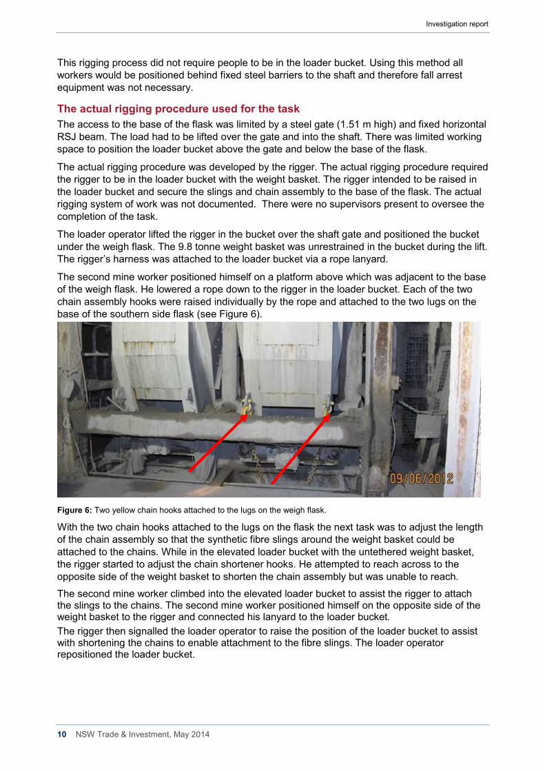
The second mine worker positioned himself on a platform above which was adjacent to the base of the weigh flask. He lowered a rope down to the rigger in the loader bucket. Each of the two chain assembly hooks were raised individually by the rope and attached to the two lugs on the base of the southern side flask (see Figure 6).
Figure 6: Two yellow chain hooks attached to the lugs on the weigh flask.
With the two chain hooks attached to the lugs on the flask the next task was to adjust the length of the chain assembly so that the synthetic fibre slings around the weight basket could be attached to the chains. While in the elevated loader bucket with the untethered weight basket, the rigger started to adjust the chain shortener hooks. He attempted to reach across to the opposite side of the weight basket to shorten the chain assembly but was unable to reach.
The second mine worker climbed into the elevated loader bucket to assist the rigger to attach the slings to the chains. The second mine worker positioned himself on the opposite side of the weight basket to the rigger and connected his lanyard to the loader bucket. The rigger then signalled the loader operator to raise the position of the loader bucket to assist with shortening the chains to enable attachment to the fibre slings. The loader operator repositioned the loader bucket.
Investigation report
11 NSW Trade & Investment, May 2014
The worker’s fall from the loader bucket When the loader bucket came to a halt, there was a jerking motion of the bucket and the bucket tilted forward. The rigger and the weight basket fell out of the front of the loader bucket and fell into the shaft. The rigger fell about 14 metres to the base of the shaft. The second mine worker did not fall. The second mine worker saw the rigger and the weight basket fall from the bucket at the same time. The loader operator in the cabin of the loader also saw the weight basket fall but did not see the rigger fall. The rigger’s right leg was severed during the fall. He also suffered three spinal fractures, seven broken ribs and a lacerated liver.
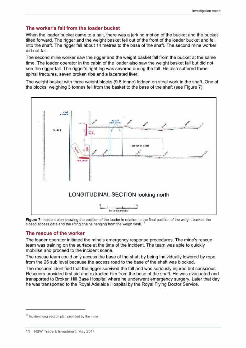
The weight basket with three weight blocks (9.8 tonne) lodged on steel work in the shaft. One of the blocks, weighing 3 tonnes fell from the basket to the base of the shaft (see Figure 7).
Figure 7: Incident plan showing the position of the loader in relation to the final position of the weight basket, the closed access gate and the lifting chains hanging from the weigh flask.15
The rescue of the worker The loader operator initiated the mine’s emergency response procedures. The mine’s rescue team was training on the surface at the time of the incident. The team was able to quickly mobilise and proceed to the incident scene. The rescue team could only access the base of the shaft by being individually lowered by rope from the 26 sub level because the access road to the base of the shaft was blocked. The rescuers identified that the rigger survived the fall and was seriously injured but conscious. Rescuers provided first aid and extracted him from the base of the shaft. He was evacuated and transported to Broken Hill Base Hospital where he underwent emergency surgery. Later that day he was transported to the Royal Adelaide Hospital by the Royal Flying Doctor Service.
15 Incident long section plan provided by the mine
Investigation report
12 NSW Trade & Investment, May 2014
Training and experience The rigger worked at the mine in a variety of roles for 35 years and had been a rigger for over 15 years. The rigger held certificates of competency as a Dogman (Class 2) and Rigger (Class 1) issued in 1986. The rigger also held competencies in ‘working at heights’ issued in 2007 and 2011. The rigger completed a one day working at heights course in 2007. In 2011, the rigger was deemed competent in ‘working at heights’ through recognition of prior learning.
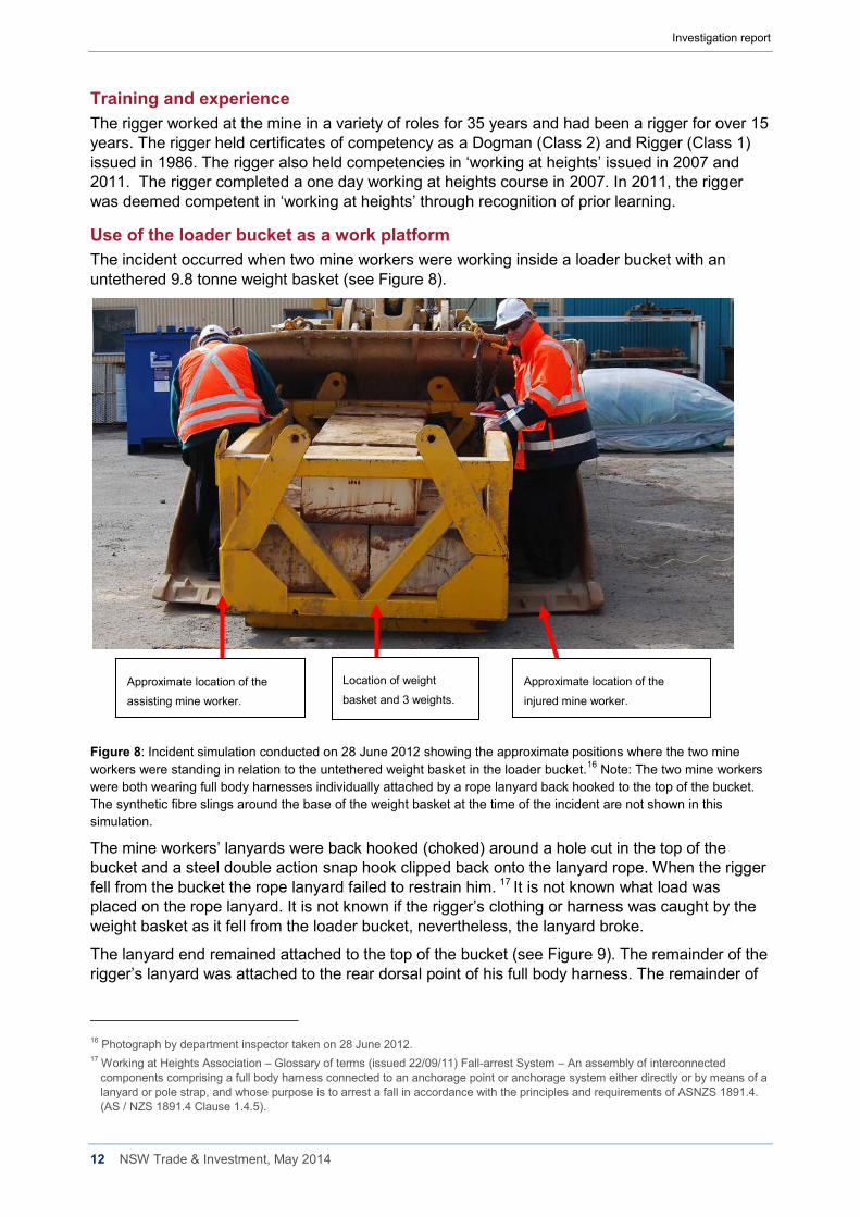
Use of the loader bucket as a work platform The incident occurred when two mine workers were working inside a loader bucket with an untethered 9.8 tonne weight basket (see Figure 8).
Figure 8: Incident simulation conducted on 28 June 2012 showing the approximate positions where the two mine workers were standing in relation to the untethered weight basket in the loader bucket.16 Note: The two mine workers were both wearing full body harnesses individually attached by a rope lanyard back hooked to the top of the bucket. The synthetic fibre slings around the base of the weight basket at the time of the incident are not shown in this simulation.
The mine workers’ lanyards were back hooked (choked) around a hole cut in the top of the bucket and a steel double action snap hook clipped back onto the lanyard rope. When the rigger fell from the bucket the rope lanyard failed to restrain him. 17 It is not known what load was placed on the rope lanyard. It is not known if the rigger’s clothing or harness was caught by the weight basket as it fell from the loader bucket, nevertheless, the lanyard broke.
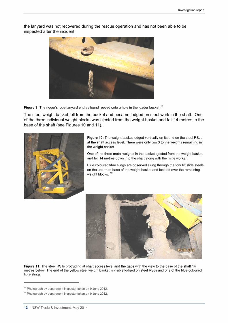
The lanyard end remained attached to the top of the bucket (see Figure 9). The remainder of the rigger’s lanyard was attached to the rear dorsal point of his full body harness. The remainder of
16 Photograph by department inspector taken on 28 June 2012. 17 Working at Heights Association – Glossary of terms (issued 22/09/11) Fall-arrest System – An assembly of interconnected
components comprising a full body harness connected to an anchorage point or anchorage system either directly or by means of a lanyard or pole strap, and whose purpose is to arrest a fall in accordance with the principles and requirements of ASNZS 1891.4. (AS / NZS 1891.4 Clause 1.4.5).
Approximate location of the
injured mine worker. Approximate location of the
assisting mine worker.
Location of weight
basket and 3 weights.
Investigation report
13 NSW Trade & Investment, May 2014
the lanyard was not recovered during the rescue operation and has not been able to be inspected after the incident.
Figure 9: The rigger’s rope lanyard end as found reeved onto a hole in the loader bucket.18
The steel weight basket fell from the bucket and became lodged on steel work in the shaft. One of the three individual weight blocks was ejected from the weight basket and fell 14 metres to the base of the shaft (see Figures 10 and 11).
Figure 10: The weight basket lodged vertically on its end on the steel RSJs at the shaft access level. There were only two 3 tonne weights remaining in the weight basket
One of the three metal weights in the basket ejected from the weight basket and fell 14 metres down into the shaft along with the mine worker.
Blue coloured fibre slings are observed slung through the fork lift slide steels on the upturned base of the weight basket and located over the remaining weight blocks. 19
Figure 11: The steel RSJs protruding at shaft access level and the gaps with the view to the base of the shaft 14 metres below. The end of the yellow steel weight basket is visible lodged on steel RSJs and one of the blue coloured fibre slings.
18 Photograph by department inspector taken on 9 June 2012. 19 Photograph by department inspector taken on 9 June 2012.
Investigation report
14 NSW Trade & Investment, May 2014
7. Post incident observations of loader functionality On 28 June 2012, investigators conducted functionality observations of the Caterpillar front end loader involved in the incident. The second mine worker involved in the incident assisted investigators to determine the approximate position of the weight basket in the loader bucket when the incident occurred.
The observations sought to determine the position at which loss of friction occurred between the steel weight basket and the steel loader bucket floor. A secondary purpose was to observe the operational functionality of the loader during the lifting activity. A third purpose was to determine if the seated loader operator could see the base of the weight basket when the bucket was in an elevated position.
An inclinometer was attached to the frame of the weight basket to observe the angle of inclination during the lifting and tilting actions of the loader bucket. The basket was secured to the loader bucket via loose chains to ensure that it did not fall from the bucket during operation.
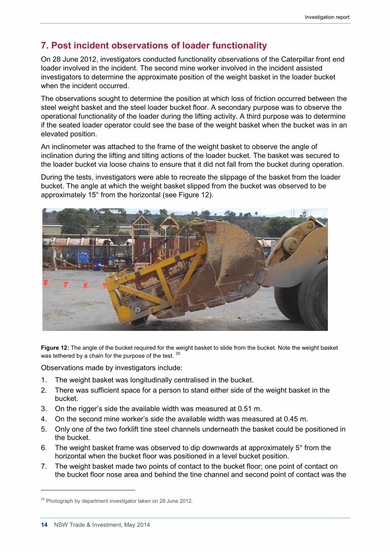
During the tests, investigators were able to recreate the slippage of the basket from the loader bucket. The angle at which the weight basket slipped from the bucket was observed to be approximately 15° from the horizontal (see Figure 12).
Figure 12: The angle of the bucket required for the weight basket to slide from the bucket. Note the weight basket was tethered by a chain for the purpose of the test. 20
Observations made by investigators include:
1. The weight basket was longitudinally centralised in the bucket. 2. There was sufficient space for a person to stand either side of the weight basket in the
bucket. 3. On the rigger’s side the available width was measured at 0.51 m. 4. On the second mine worker’s side the available width was measured at 0.45 m. 5. Only one of the two forklift tine steel channels underneath the basket could be positioned in
the bucket. 6. The weight basket frame was observed to dip downwards at approximately 5° from the
horizontal when the bucket floor was positioned in a level bucket position. 7. The weight basket made two points of contact to the bucket floor; one point of contact on
the bucket floor nose area and behind the tine channel and second point of contact was the
20 Photograph by department investigator taken on 28 June 2012.
Investigation report
15 NSW Trade & Investment, May 2014
tine channel inside the bucket. All points of contact were steel on steel contact between the weight basket and the bucket floor.
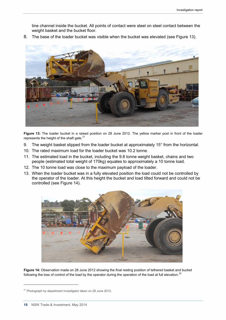
8. The base of the loader bucket was visible when the bucket was elevated (see Figure 13).
Figure 13: The loader bucket in a raised position on 28 June 2012. The yellow marker post in front of the loader represents the height of the shaft gate.21
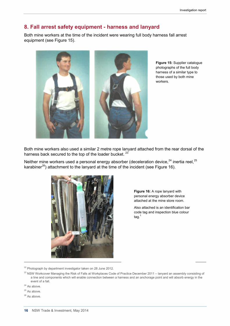
9. The weight basket slipped from the loader bucket at approximately 15° from the horizontal. 10. The rated maximum load for the loader bucket was 10.2 tonne. 11. The estimated load in the bucket, including the 9.8 tonne weight basket, chains and two
people (estimated total weight of 170kg) equates to approximately a 10 tonne load. 12. The 10 tonne load was close to the maximum payload of the loader. 13. When the loader bucket was in a fully elevated position the load could not be controlled by
the operator of the loader. At this height the bucket and load tilted forward and could not be controlled (see Figure 14).
Figure 14: Observation made on 28 June 2012 showing the final resting position of tethered basket and bucket following the loss of control of the load by the operator during the operation of the load at full elevation.22
21 Photograph by department investigator taken on 28 June 2012.
Investigation report
16 NSW Trade & Investment, May 2014
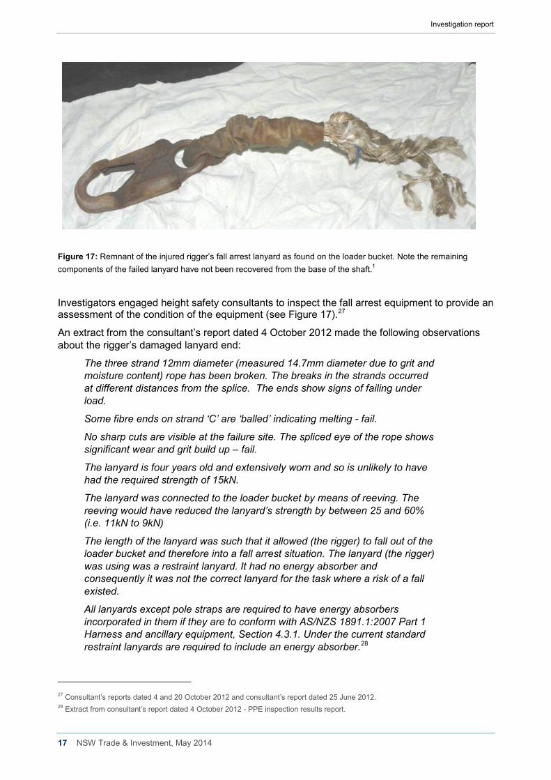
8. Fall arrest safety equipment - harness and lanyard Both mine workers at the time of the incident were wearing full body harness fall arrest equipment (see Figure 15).
Figure 15: Supplier catalogue photographs of the full body harness of a similar type to those used by both mine workers.
Both mine workers also used a similar 2 metre rope lanyard attached from the rear dorsal of the harness back secured to the top of the loader bucket. 23
Neither mine workers used a personal energy absorber (deceleration device,24 inertia reel,25 karabiner26) attachment to the lanyard at the time of the incident (see Figure 16).
22 Photograph by department investigator taken on 28 June 2012. 23 NSW Workcover Managing the Risk of Falls at Workplaces Code of Practice December 2011 – lanyard an assembly consisting of
a line and components which will enable connection between a harness and an anchorage point and will absorb energy in the event of a fall.
24 As above. 25 As above. 26 As above.
Figure 16: A rope lanyard with personal energy absorber device attached at the mine store room.
Also attached is an identification bar code tag and inspection blue colour tag.1
Investigation report
17 NSW Trade & Investment, May 2014
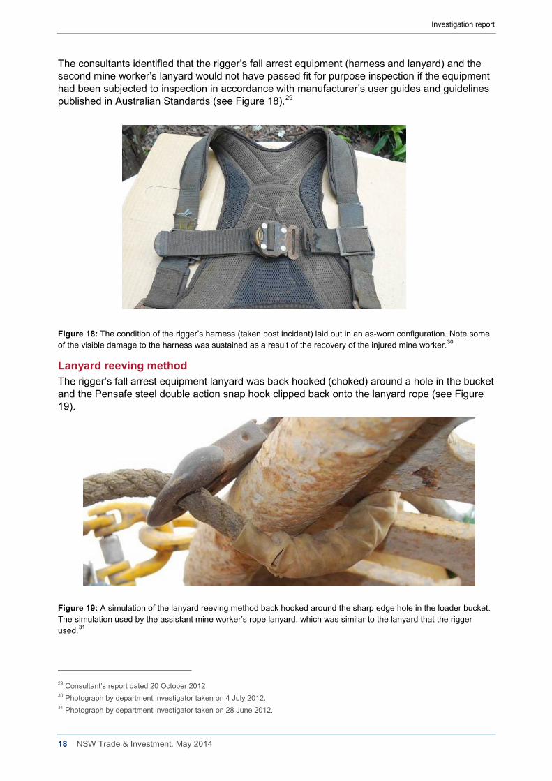
Figure 17: Remnant of the injured rigger’s fall arrest lanyard as found on the loader bucket. Note the remaining components of the failed lanyard have not been recovered from the base of the shaft.1
Investigators engaged height safety consultants to inspect the fall arrest equipment to provide an assessment of the condition of the equipment (see Figure 17).27
An extract from the consultant’s report dated 4 October 2012 made the following observations about the rigger’s damaged lanyard end:
The three strand 12mm diameter (measured 14.7mm diameter due to grit and moisture content) rope has been broken. The breaks in the strands occurred at different distances from the splice. The ends show signs of failing under load.
Some fibre ends on strand ‘C’ are ‘balled’ indicating melting - fail.
No sharp cuts are visible at the failure site. The spliced eye of the rope shows significant wear and grit build up – fail.
The lanyard is four years old and extensively worn and so is unlikely to have had the required strength of 15kN.
The lanyard was connected to the loader bucket by means of reeving. The reeving would have reduced the lanyard’s strength by between 25 and 60% (i.e. 11kN to 9kN)
The length of the lanyard was such that it allowed (the rigger) to fall out of the loader bucket and therefore into a fall arrest situation. The lanyard (the rigger) was using was a restraint lanyard. It had no energy absorber and consequently it was not the correct lanyard for the task where a risk of a fall existed.
All lanyards except pole straps are required to have energy absorbers incorporated in them if they are to conform with AS/NZS 1891.1:2007 Part 1 Harness and ancillary equipment, Section 4.3.1. Under the current standard restraint lanyards are required to include an energy absorber.28
27 Consultant’s reports dated 4 and 20 October 2012 and consultant’s report dated 25 June 2012. 28 Extract from consultant’s report dated 4 October 2012 - PPE inspection results report.
Investigation report
18 NSW Trade & Investment, May 2014
The consultants identified that the rigger’s fall arrest equipment (harness and lanyard) and the second mine worker’s lanyard would not have passed fit for purpose inspection if the equipment had been subjected to inspection in accordance with manufacturer’s user guides and guidelines published in Australian Standards (see Figure 18).29
Figure 18: The condition of the rigger’s harness (taken post incident) laid out in an as-worn configuration. Note some of the visible damage to the harness was sustained as a result of the recovery of the injured mine worker.30
Lanyard reeving method The rigger’s fall arrest equipment lanyard was back hooked (choked) around a hole in the bucket and the Pensafe steel double action snap hook clipped back onto the lanyard rope (see Figure 19).
Figure 19: A simulation of the lanyard reeving method back hooked around the sharp edge hole in the loader bucket. The simulation used by the assistant mine worker’s rope lanyard, which was similar to the lanyard that the rigger used.31
29 Consultant’s report dated 20 October 2012 30 Photograph by department investigator taken on 4 July 2012. 31 Photograph by department investigator taken on 28 June 2012.
Investigation report
19 NSW Trade & Investment, May 2014
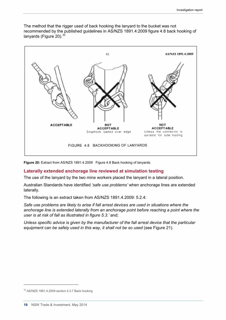
The method that the rigger used of back hooking the lanyard to the bucket was not recommended by the published guidelines in AS/NZS 1891.4:2009 figure 4.8 back hooking of lanyards (Figure 20).32
Figure 20: Extract from AS/NZS 1891.4.2009 Figure 4.8 Back hooking of lanyards.
Laterally extended anchorage line reviewed at simulation testing The use of the lanyard by the two mine workers placed the lanyard in a lateral position.
Australian Standards have identified ‘safe use problems’ when anchorage lines are extended laterally.
The following is an extract taken from AS/NZS 1891.4.2009: 5.2.4:
Safe use problems are likely to arise if fall arrest devices are used in situations where the anchorage line is extended laterally from an anchorage point before reaching a point where the user is at risk of fall as illustrated in figure 5.3.’ and;
Unless specific advice is given by the manufacturer of the fall arrest device that the particular equipment can be safely used in this way, it shall not be so used (see Figure 21).
32 AS/NZS 1891.4.2009 section 4.3.7 Back hooking
Investigation report
20 NSW Trade & Investment, May 2014
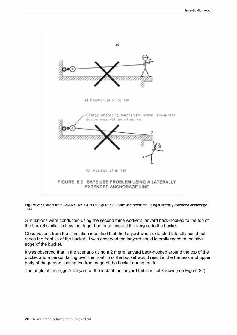
Figure 21: Extract from AS/NZS 1891.4.2009 Figure 5.3 - Safe use problems using a laterally extended anchorage lines. Simulations were conducted using the second mine worker’s lanyard back-hooked to the top of the bucket similar to how the rigger had back-hooked the lanyard to the bucket.
Observations from the simulation identified that the lanyard when extended laterally could not reach the front lip of the bucket. It was observed the lanyard could laterally reach to the side edge of the bucket.
It was observed that in the scenario using a 2 metre lanyard back-hooked around the top of the bucket and a person falling over the front lip of the bucket would result in the harness and upper body of the person striking the front edge of the bucket during the fall.
The angle of the rigger’s lanyard at the instant the lanyard failed is not known (see Figure 22).
Investigation report
21 NSW Trade & Investment, May 2014
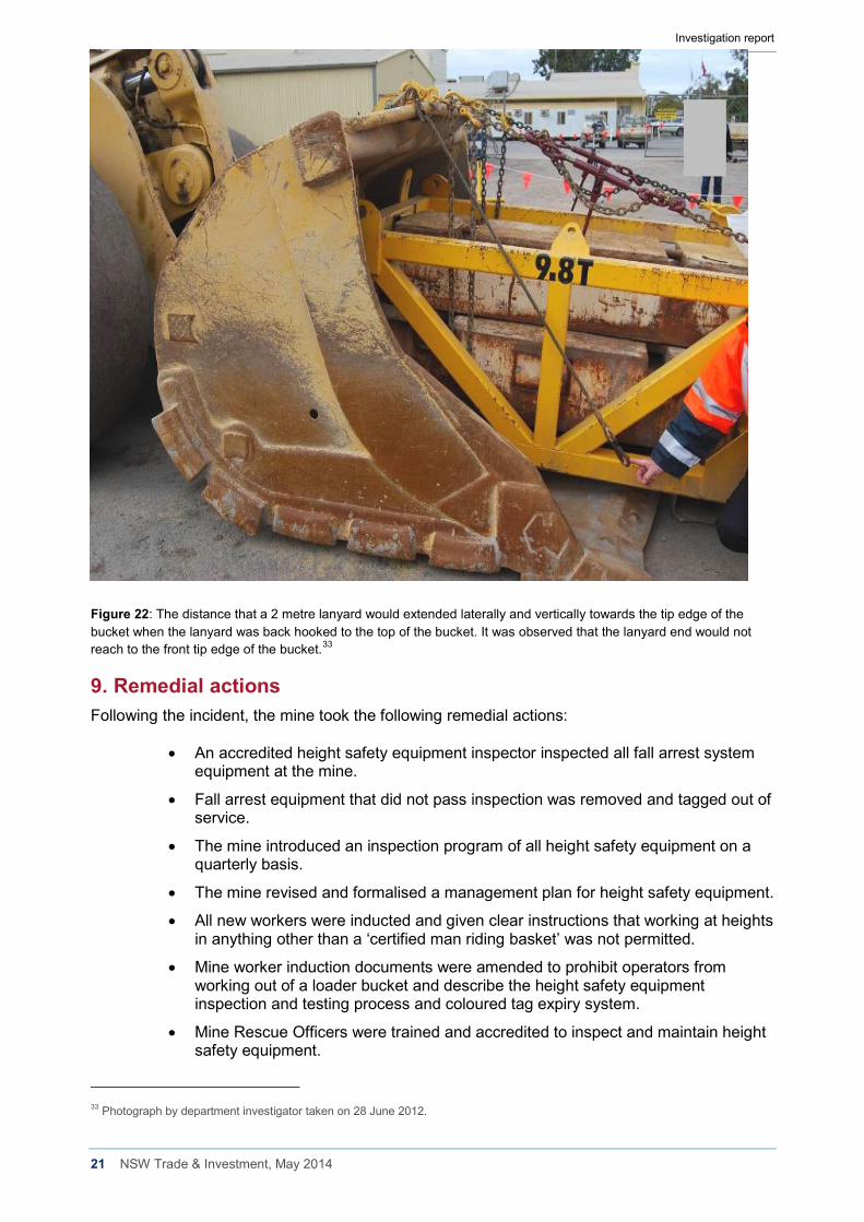
Figure 22: The distance that a 2 metre lanyard would extended laterally and vertically towards the tip edge of the bucket when the lanyard was back hooked to the top of the bucket. It was observed that the lanyard end would not reach to the front tip edge of the bucket.33
9. Remedial actions Following the incident, the mine took the following remedial actions:
• An accredited height safety equipment inspector inspected all fall arrest system equipment at the mine.
• Fall arrest equipment that did not pass inspection was removed and tagged out of service.
• The mine introduced an inspection program of all height safety equipment on a quarterly basis.
• The mine revised and formalised a management plan for height safety equipment.
• All new workers were inducted and given clear instructions that working at heights in anything other than a ‘certified man riding basket’ was not permitted.
• Mine worker induction documents were amended to prohibit operators from working out of a loader bucket and describe the height safety equipment inspection and testing process and coloured tag expiry system.
• Mine Rescue Officers were trained and accredited to inspect and maintain height safety equipment.
33 Photograph by department investigator taken on 28 June 2012.
Investigation report
22 NSW Trade & Investment, May 2014
• All height safety equipment was required to be stored in the safety store and issued on a shift by shift basis. A trained and accredited Mines Rescue Officer was to inspect it when it was returned to the store at the end of the shift.
• Any defective equipment was taken out of service until it was inspected by an external accredited height safety equipment inspector during the next quarterly visit to site.
• New harnesses and lanyards came into the system only after they were inspected, tagged and marked with a unique identification and added to the equipment register.
• Every item in the height safety equipment register was inspected and certified as ‘fit for purpose’ on a quarterly basis.
• All height safety equipment in use was required to display the nominated colour tag to verify that it was ‘fit for use’.
• The mine communicated the incident to the workforce and provided information about the injured workers’ conditions and the impact on the mine’s operation.
• Safety meetings were held where a PowerPoint presentation was delivered to all workers and included the department’s Safety Alert (SA 12-03) Worker loses leg in fall.
• The Perilya Mine Health and Safety Committee members were included in the information meetings and two committee members were involved in the incident investigation team.
10. Conclusion This incident resulted in a rigger falling from an elevated loader bucket about 14 metres to the base of a vertical mine haulage shaft and suffering serious injuries.
The investigation identified a range of factors that contributed to the incident, summarised below.
Safe work practices
• This was the first time the mine workers had undertaken the task.
• The system of work envisaged by mine supervisors was not the system of work the mine workers used to undertake the task.
• The task documentation created by mine supervisors did not specifically identify how the work task was to be performed.
• Verbal discussions had taken place between supervisors and the rigger before the incident but safe work procedures were not documented.
• The use of the loader bucket as an elevated work platform was not permitted by the mine. However, this prohibition was not specifically documented in mine procedures.
Fit-for-purpose equipment
• The loader bucket was not designed to be used as an elevated work platform.
• The loader bucket was not designed to be used for the purpose of lifting steel weight baskets or people.
• The fall arrest system used did not restrain the rigger’s fall.
• There was no energy absorbing device incorporated in the rigger’s fall arrest system.
Investigation report
23 NSW Trade & Investment, May 2014
• The method used by the rigger to connect the lanyard to the loader bucket was not recommended in the published guidelines in AS/NZS 1891.4:2009.
• The fall arrest system equipment that the two mine workers used had not been stored and inspected under the mine’s fall arrest equipment storage and inspection system.
• Several components of the fall arrest equipment used by the two mine workers would not have been passed a ‘fit for purpose’ inspection.
Competent people
• Supervisors involved in the task planning did not document how the task was to be performed.
• Task assessment documentation created by the rigger was inadequate and was not reviewed by the supervisors who had planned the task.
• There was no supervisory oversight of the task being undertaken.
• The rigger held certificates of competency as a Dogman (Class 2) and Rigger (Class 1). The rigger’s working at heights competencies were obtained following a one day training course completed in 2007 and recognition of prior learning in 2011.
11. Recommendations The preliminary findings of the investigation and recommendations were published by the department in Safety Alert (SA12-03) Worker loses leg in fall on 27 June 2012. The Safety Alert made the following recommendations to the NSW mining industry:
Review current practices and:
1. Prohibit people from working in the bucket of a front end loader or other similar apparatus.
2. When working at heights:
• Ensure compliance with the provisions of the Work Health and Safety Regulation 2011 (WHSR) Part 4.4 Falls.
• Consider the Model Code of Practice – Managing the Risk of Falls at Workplaces. See www.safeworkaustralia.gov.au
• Include in ‘fall from height’ protocols provision for training and instruction in fit-for-purpose equipment to ensure it is properly stored, tested, maintained and discarded where appropriate.
3. When lifting people:
• Ensure compliance with provisions of clause 219 and clause 220 of the WHSR, in particular that the workers are lifted or suspended in a work box.
• Use fit for purpose elevated work platforms with consideration to AS 2550, AS1418.10 and the recommendation in Safety Alert SA08-09 Workers injured on work platform attached to load haul dump. Note: elevated work platforms manufactured after 1 December 2003 must be design registered. See Schedule 5 of the WHSR.
4. When meeting obligations under Part 3.1 WHSR, ensure:
• Risk control measures are implemented in accordance with the hierarchy of controls.
Investigation report
24 NSW Trade & Investment, May 2014
• Safe systems of work are:
o developed through competent people
o developed through effective consultation
o effectively communicated
o consistent with established methodologies – refer to Risk Management Standard AS/NZS ISO 3100
5. In accordance with clause 37 and clause 38 of the WHSR, ensure competent people are involved in reviewing the adequacy and maintenance of risk controls.