Embed Size (px)
Citation preview
www.jgtte.com
51
Received 10/9/2016 Accepted 11/26/2015
Published 12/1/2016
Corresponding Author:
B. Uge; [email protected]/
Journal of Geotechnical and Transportation Engineering
Volume 2 | Issue 2
Investigation on the Swelling Characteristics and Unsatu-
rated Shear Strength of Expansive Soils ...
Uge
Investigation on the Swelling characteristics and
unsaturated shear strength of expansive soils
from Arba Minch in Ethiopia
Bantayehu Uba Uge
MSc, School of Civil Engineering, Hawassa University, Hawassa, Ethiopia
Email: [email protected]/[email protected]
Abstract
In Ethiopia, many researches were done on characterizing
expansive soils but only a very limited number of studies were
conducted on Addis Ababa expansive soil, exists on the unsaturated
shear strength behavior. The present study addresses examining
expansive soils in Arba Minch – a town in the Rift Valley with great
portion of its terrain covered by the same soil but not considered
previously. Laboratory-testing program was planned and performed
on undisturbed soil samples taken from 10 locations for swelling
pressure testing; and among these, one pit was allotted for
unsaturated shear strength study. The laboratory test results
revealed swelling pressure ranges from 74.53 to 571.29 kPa,
Plasticity Index from 49 to 77%, Shrinkage Index from 81 to 117%
and Free Swell from 94.0 to 165.0%. The results from unsaturated
shear strength tests performed with a 50kN modified double wall
triaxial machine on an undisturbed sample setting matric suction
100 kPa, 150 kPa and 200kPa for an effective consolidation
pressure of 200kPa have clearly indicated the saturated case to yield
smaller shear strength than the unsaturated one. The maximum
deviator stress showed to increase from 107.61kPa to 174.35kPa
with an increase in matric suction but the shape of the stress-strain
diagram remained identical.
Keyword: Unsaturated Shear Strength, Expansive Soil, Laboratory
Testing, Swelling Behavior
1. Introduction
1.1. The Present Problems of Expansive Soils
The worldwide spread problematic expansive soils have got a
great deal of attention due to its alarming amount of damage in the
locality of its occurrence. Scholars have tried to tackle the problem
focusing on examining the nature and mechanism of swell-shrink
behavior and developing empirical equations to predict the swelling
pressure from the basic soil index properties. However, several
considerations within the past two decades or so have shown an
increasing interest of geotechnical investigators in the unsaturated
state of these soils upon the development of advanced testing
equipment and techniques, which permit the control of pore- air
pressure in the test sample.
Expansive soils are clay soils with high plasticity (i.e. high liquid
limit) known for their peculiar nature of expanding or shrinkage
when exposed to moisture changes. During dry seasons, they shrink
forming cracks and swell during wet periods causing most damage
to structures particularly light buildings such as houses, apartments,
warehouses, small industrial buildings, and pavements in several
areas of the world. Aytekin [5] explained that, in the United States
alone, expansive clay has been estimated to produce annual
damages of $1.7 billion on streets and highways and more than $9.0
billion on all structures on expansive soils. The damage turns to be
more than double the cost associated with repair to damage from
floods, hurricanes, tornadoes, and earthquakes [3, 11]. As well, in
Sudan, expansive soils have caused an estimated annual damage of
$6.0 million to irrigation systems, water lines, sewer lines, buildings,
roads, and other structures [5].
The problems with expansive soils are still manifested globally.
Ethiopia is among the countries that have reported internationally
their problems at research conferences [1, 2, 11, 16, 33, 34]. The
damages will be much greater in coming years if expansive soils are
not recognized before builders start to build structures in/on
expansive soils [5]. Sisay [30], under his study on damage
assessment of buildings constructed on expansive soils of Addis
Ababa, has found 64% of the randomly surveyed buildings to be
adversely affected. Similarly, Sime [31] indicated that most of the
roads constructed failed before their expected design life, in some
cases after few months of completion and Teklu [35] on his study
on swelling pressure of Addis Ababa expansive soil also
enlightened a lot of damages being occurring to civil engineering
construction due to expansive soils, even if no organized economic
survey has been made in the country.

52
Journal of Geotechnical and Transportation Engineering - 2016 vol. 2 (2)
Resource Oriented Sanitation concepts for peri-urban areas in
Africa – ROSA (2009) in their sanitation project in Arba Minch
town indicated a significant portion of the town to comprise loose
black cotton soil, which is an expansive clay with high potential for
shrinking or swelling as a result of changing moisture content, in
which pit collapse is a major problem. Additional researches Tests
performed in Addis Ababa, Mekelle, Bahir Dar, Gambela and
Hawassa confirm that much has been done on characterizing the
behavior of the expansive soil and its distribution in Ethiopia [22,
37, 41]. Moreover, the outcomes of these investigations forwarded
various forms of empirical equations which relate swelling behavior
to certain physical properties of the soil which are well understood
by practicing engineers.
The degree of expansiveness depends on whether the soil mass
contains active clay minerals or not. The three most important
groups of clay minerals are Montmorillonite, Illite, and Kaolinite,
which are crystalline hydrous aluminosilicate. Of these groups,
Montmorillonite is the clay mineral that is mostly present in
expansive soil and responsible for its expansive nature. When these
minerals are exposed to moisture, water is absorbed between the
inter-layering lattice structures and exerts an upward pressure,
which is the cause for most damages associated with expansive soil.
The damages can occur within a few months following construction,
may develop slowly over a period of about 5 years, or may not
appear for many years until some activity occurs to disturb the soil
moisture [11].
1.2. Motivation and Objective of the Study
As mentioned above, in Ethiopia, most research works on
expansive soils were concentrated around Addis Ababa whilst very
little have been made on regional towns. The focus of the researches
was somewhat inclined on its characterization, blending it with
chemicals to mitigate its poor quality, the damages it resulted and
its distribution in Ethiopia but Tilahun [37] in continuation to the
work of Zewdie [41] studied its shear strength characteristic based
on Unconsolidated Undrained triaxial tests (UU) performed on
saturated and unsaturated samples apprizing that suction can have
major influence on the shear strength. Recently, Gebre [17] has
carried out the unsaturated shear strength characteristic and stress-
strain behavior of expansive soils still from Addis Ababa. However,
depending upon the type of material, climate and topography, the
engineering properties of expansive soils varies from place to place
[11]; thus requiring the behavior of the same soil to be investigated
in the other localities of the country. In this study investigation is
done on the swell potential, swelling pressure and the unsaturated
shear strength characteristic of expansive soils of Arba Minch – one
of the towns where no such investigation has been conducted so far,
even though expansive soil of residual deposit type covers most of
its terrain.
1.3. Description of the Study Area
Arba Minch, with a population of 75,000 and annual population
growth rate of 4.5% is one of the fast growing towns in Ethiopia. It
was founded in 1960s and received its name from the abundant local
springs which produce a groundwater forest. The town is located in
Gamo Gofa zone, the Southern Nations, Nationalities and Peoples
Region. To put this in a geographical positioning way, Arba Minch
is located at the floor of the southern part of the East African Rift
Valley between 6030’N to 6008’N latitude and 37 33’E to 37 37’E
longitude at an elevation of 1285m above sea level [6,12].
Arba Minch town consists of the uptown administrative center of
Shecha and 4km away the downtown commercial and residential
areas of Sikela, which are connected by a paved road. Recently, it
is divided into four sub-cities which are restructured into eleven
administrative kebeles. The area administered by the municipality
extends up to 20.8km2 and the expansion is fast particularly after
1980’s due to the establishment of different institutions and rapid
flow of rural migrants. The climate of Arba Minch area is
categorized as semi-arid. The mean annual rainfall, temperature,
humidity, sunshine hours are about 750mm, 25 C, 57%, 7.5 hours,
respectively [6].
Geologically, the area belongs to the category of the Rift Valley
system. The geological units in the Rift Valley region are mainly the
result of volcanic activity during the Tertiary period. The whole Rift
Valley is underlain by ancient basement rocks, which are defined as
genesis grading in metamorphic granites, ignimbrites (consolidated
hot-ash flows) and granodiorites. A more recent layer of volcanic
rocks and ignimbrites has been added over the basement [15]. Förch
[15] again referred basaltic flow and related spatter cones to be the
major geologic units from which the well-known ’forty springs’
flow. ROSA (2009) in their sanitation project of the town indicated
a significant portion of the town to comprise loose black cotton soil
in which pit collapse is a major problem. They highlighted the other
part by saying to have rocky ground where digging is very difficult.
1.4. Scope of the Investigation
In order to address the aforementioned purposes, ten test pits
were dug in the town at different locations where expansive soils
prevail as part of this work. The sites for the test pits were selected
systematically and are depicted in Figure 1. Undisturbed and
disturbed samples were extracted from each test pit for Swelling
pressure, Shear strength, and Index property tests. Among the rest,
one pit was chosen for further unsaturated shear strength
characteristic investigation where only undisturbed samples being
used for both the conventional and the modified triaxial testing.
The depth of the pits varied from 1.0m to 2.5m (as it is frequent
on the study area to place the foundation around these depths unless
a basement construction forces further). The results from this
research can be used in identifying and estimating the behavior of
the expansive soil of the area so that possible measures can be taken
to reduce the problems arising to the structures during and after
construction. It can also serve as a resource for further investigation
on expansive clay soil, especially the unsaturated state, in the other
locality of the country.
2. Expansive soils behavior, Laboratory Test
Result and Discussion
2.1. Identification and Classification of Expansive Soils

53
Uge
A major concern in geotechnical engineering is identification
of expansive soils, either in the field (by their color, shrinkage
crack, shiny surface etc. as stated in Murthy, [25,35]) or
laboratory [such as mineralogical (X-ray diffraction, Differential
thermal analysis, Dye absorption, Electron microscope, Base
Exchange capacity, etc)], direct (actual physical measurement
of swelling) and indirect (involving the use of indirect
information from soil index and physical properties)
identification techniques ( as stated in Chen, [11], and Tilahun,
[37]) , and estimation of their swelling magnitudes when subjected
to changes in environment so that problems posed by them can be
counteracted [3]. Geotechnical engineers generally prefer the
Unified Soil Classification System – USCS while the American
Association of State Highway and Transportation Officials –
AASHTO classification is common in state and country highway
departments [13].
Figure 1. Location of test pits.
Accordingly, with USCS, the soils from AMU-HSC and that
around Wubete Hotel touch the A-line with the rest falling near
below it, based on laboratory tests. Similarly, AASHTO classifies
the soil under interest as plastic clay having high volume change
capacity between wet and dry states.
According to Single Index Method of classification of Seed,
Woodward and Lundgreen [11], Plasticity Index of the soil of the
study area reveals that the soil falls in the range of very high swelling
potential.
(a)
(b)
Figure 2. Plasticity chart of the study area according to (a) USCS and (b) AASHTO
Moreover, Altmayer’s [11] measure of potential expansiveness
based on Shrinkage Limit indicates the soils at the Edgetber kebele
exhibit critical degree of expansion, those around Wubete Hotel,
Woreda Firdbet, Shecha Highschool and Chamo kebele on a
marginal state and the rest being non critical.
2.2. Mechanics of Swelling
Chen [11] deeply explained that effect of water on expansive soil is
54
Journal of Geotechnical and Transportation Engineering - 2016 vol. 2 (2)
the major concern to practicing engineers as the complex pattern and
magnitude of expansion cannot be predicted by the classical elastic
or plastic theory. In general, the swell-shrink potential is affected
by the soil characteristics that influence the basic nature of the
internal force field, the environmental factors that influence the
changes that may occur on the internal force system, and the state
of stress.
The swelling pressure test was done according to Method A (Swell
- Consolidation test) of ASTM D 4546 -96 with the seating pressure
of 7 k Pa and AST M D422 -63 was followed to carry out wet sieve
and hydrometer analysis on disturbed sample. BS -1377 -2: 1990 is
followed for Atterberg limits testing and ASTM D 854 -83 for
Specific Gravity test. The results are shown in Table 1.
2.3. Unsaturated Soil Mechanics
In tropical and arid regions, even in temperate climatic zones
soils exist above the ground water table and remain partially
saturated/ unsaturated. Tropical and arid regions of the world
comprise more than one-third of the earth's surface. Soils in these
regions are dry and desiccated near the ground surface. These
conditions may exist to a considerable depth below the ground
surface. Expansive soils are residual soils generally located in these
regions and are usually in an unsaturated state [19]. Several
International conferences on Expansive soils held to eliminate
the excessive financial losses due to their problem have been
the subject, if not the driving force, of unsaturated soil research
since the early stages in the formulation of unsaturated soil
mechanics principles [1, 32, 24]. The compacted soils used in
several engineering constructions, such as earth dams, highways,
embankments, and airport runways, are unsaturated soils.
2.3.1. Concept of Soil Suction
Soil suction, more often used in expansive soil studies, is a
parameter describing the state of the soil and indicates the intensity
with which it will attract water [11]. It is commonly referred to as
the free energy state of soil water. The free energy of the
soil water can be measured in terms of the partial vapor
pressure of the soil water. The theoretical concept of suction
was developed in early 1900’s and this concept was first applied to
unsaturated soils by United States Road Research Laboratory, now
known as United States Transport Research Laboratory [10].
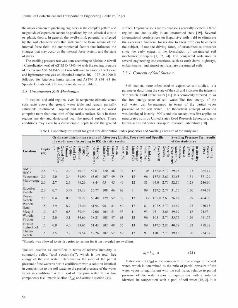
Table 1. Laboratory test result for grain size distribution, Index properties and Swelling Pressure of the study area.
Location Depth (m)
Grain size distribution results of
the study area (According to BS)
Atterberg Limits, Free swell and Specific
Gravity results
Swelling Pressure Test results
of the study area
Grav
el (%)
(size>2
.00m
m)
Sa
nd
(%)
(0.0
06-
2.0
mm
)
Silt (%
) (0
.00
2-
0.0
06m
m)
Cla
y (%
) (<
0.0
02
mm
)
Liq
uid
L
imit (%
)
Pla
stic
Lim
it (%)
Pla
stic
ind
ex (%
)
Vo
lum
etric
Sh
rink
ag
e
Lim
it (%)
Sh
rink
ag
e
ind
ex (%
)
Free S
well
(%)
Sp
ecific G
rav
ity
Na
tura
l
mo
isture
con
tent (%
) (G
ravim
etri
In situ
dry
den
sity,
d
(gm
/cc)
Sw
elling
Pressu
re (k
Pa
)
AMU –HSC*
2.5 2.3 2.9 40.13 54.67 120 46 74 12 108 137.0 2.72 29.03 1.23 265.17
Yetnebersh 2.0 2.0 2.4 31.99 63.63 107 49 58 12 96 137.5 2.69 33.65 1.31 571.29 Muluwengel
2.0 2.7 2.6 46.26 48.44 95 45 49 12 83 94.0 2.70 32.50 1.28 246.60
Edgetber Kebele
2.0 0.7 3.49 39.13 56.77 108 46 62 9 99 127.5 2.74 31.76 1.30 494.77
Doysa Kebele
2.0 0.4 0.9 30.22 68.48 129 52 77 12 117 165.0 2.63 26.82 1.29 464.90
Wubete Hotel
1.5 3.9 8.7 25.46 61.94 98 41 56 17 81 107.5 2.70 32.69 1.23 250.15
Mesgid 1.0 4.7 6.8 39.44 49.06 104 51 53 11 93 95 2.66 39.19 1.18 74.53 Woreda Firdbet
1.5 2.0 5.1 34.69 58.21 108 47 61 12 96 105 2.74 35.77 1.26 481.77
Shecha highschool
1.5 0.9 4.0 33.65 61.45 102 48 55 13 89 147.5 2.80 40.78 1.22 458.28
Chamo Kebele
1.5 3.5 7.7 29.54 59.26 102 52 50 12 91 110 2.73 39.15 1.20 224.37
*Sample was allowed to air-dry prior to testing for it has revealed no swelling.
The soil suction as quantified in terms of relative humidity is
commonly called “total suction (ht)”; which is the total free
energy of the soil water determined as the ratio of the partial
pressure of the water vapor in equilibrium with a solution identical
in composition to the soil water, to the partial pressure of the water
vapor in equilibrium with a pool of free pure water. It has two
components (i.e., matric suction (hm) and osmotic suction ( )).
ht hm
Matric suction (hm) is the component of free energy of the soil
water, which is determined as the ratio of partial pressure of the
water vapor in equilibrium with the soil water, relative to partial
pressure of the water vapor in equilibrium with a solution
identical in composition with a pool of soil water [16, 2]. It is

55
Uge
usually defined as the difference between pore-air pressure (ua)
and pore-water pressure (uw) in the soil.
Osmotic suction ( ) is a reduction in relative humidity in a pore,
due to the presence of dissolved salts in pore water. For most
practical geotechnical engineering applications, chemistry of pore
fluids in the soil is not changed and soil–water content varies
within a range in which concentrations of pore fluids are not
altered significantly, and so osmotic suction appears not to be
sensitive to changes in soil–water content [11, 28]. Therefore,
for most geotechnical problems involving unsaturated soils, matric
suction changes can be substituted for total suction changes, and
vice versa. However, in the case where the salt content of the soil
is altered by chemical contamination, it is necessary to consider
osmotic suction as part of the stress state [16].
2.3.2. Stress State Variables for Unsaturated Soil
Many geotechnical problems involving saturated soils have been
successfully addressed in the conventional soil mechanics with
the help of effective stress concept as all mechanical aspects
(i.e., the volume change, seepage and shear strength behavior) of a
saturated soil are governed by the effective stress. For such a soil,
one stress state variable is enough to describe the behavior of two
phases (solid and fluid/or gas) of the soil mass. The stress state
= uwuw is the pore-water pressure [36].
Unsaturated soil is normally considered as a three-phase
system, i.e., solid, gas (air), and fluid (water). In 1977, Fredlund
and Morgenstern added the contractile skin as a fourth phase and
these four phases were used by these two authors in the stress
analysis of unsaturated soil on the basis of continuum mechanics.
Several authors tried to define a single stress state variable for
unsaturated soil but soil properties were involved in the proposed
equations. State variables used to describe the state of the stress
have to be independent of soil properties [16, 28]. Bishop in 1959
proposed the following single effective stress equation for
unsaturated soil:
(2.2)
stress parameter) is a parameter that depends on the degree of
saturation and usually assumes a value of unity for saturated soil
and zero for a dry soil, but in rare instances, may exceed one [7].
In 1961, Bishop and Donald in Fredlund and Rahardjo [16]
performed a set of triaxial shear tests on unsaturated silt where the
total stress (i.e., cell pressure), pore-air pressure, and pore-water
pressure were varied 3 ua) and (ua
uw) constant. The result of these tests lent credibility to the use
3 ua) and (ua uw) as valid stress state variables for this
type of test. Fredlund and Rahardjo [16] stated that the stress state
variables have to be created from the individual force components
acting on the solid, water and air phases, and the air-water
contractile skin. ua)
and the matric suction (ua uw). Thus, following the multiphase
continuum mechanics methodology, each of these independent
stress variables in three – dimensional space can be represented
by two independent stress tensors as follows
&
2.3.3. Shear Strength of Unsaturated Soil
The shear strength of a soil can be related to the stress state in
the soil. There is a general agreement on the use of the net stress
ua) and the matric suction (ua uw) as a stress state
variables for unsaturated soils [16], with the matric suction
providing additional shear strength component which normally is
referred to as apparent cohesion.
Fredlund and Rahardjo [16] proposed the following equation to
explain the shear strength of unsaturated soils as an extension of
the shear strength equation of Terzaghi, 1943 for saturated soil:
(2.3)
Where =shear stress on the failure plane at failure
=intercept of the “extended “Mohr –Coulomb failure envelope
on the shear stress axis where the net normal stress and the matric suction at failure are equal to zero
=net normal stress state on the failure plane at
failure
=pore –air pressure on the failure plane at failure
=angle of internal friction associated with the net normal
stress state variable,
=matric suction on the failure plane at failure
=angle indicating the rate of increase in shear strength
relative to the matric suction
The above equation reverts to the equation for a saturated soil
when the matric suction vanishes as the soil approaches saturation
[24].
2.3.3.1. Laboratory Measurement of Shear Parameters for Unsaturated Soil
In unsaturated soil testing, conventional triaxial and direct shear
test equipment require adjustment prior to use as it is essential
)()(' waa uuu
azzyzx
yzayyx
xzxyax
u
u
u
wa
wa
wa
uu
uu
uu
00
00
00
ff
'c
faf u )(
afu
'
faf u )(
fwa uu )(
b
56
Journal of Geotechnical and Transportation Engineering - 2016 vol. 2 (2)
to control the pore-air pressure within the sample independently
of the pore-water pressure. This can be achieved by using ceramic
discs which in the case of full saturation enable water to pass but
prevent air from passing through it. This value of air pressure at
which the air can pass through the ceramic disc is called the air
entry value of the disc (AEV). At this point, air enters the water
compartment, which no longer maintains continuity between the
pore-water and the water in the measuring system. The measuring
system then becomes filled with air bubbles. Ceramic discs are
available with deferent diameters, thicknesses, and air-entry values
[16].
The other issue of concern is how to apply high values of matric
suction (i.e. how to apply high negative pore-water pressure within
the soil specimen). This can also be overcome by using the axis
translation technique with modification applied to the conventional
soil testing equipment. The term axis translation, which is based
on the work by Hilf’s [20], refers to the practice of elevating
pore air pressure in unsaturated soil while maintaining the pore
water pressure at a measurable reference value, typically
atmospheric [16]. As such, the matric suction variable may be
controlled over a range far greater than the cavitation limit for water
under negative pressure. The origin of reference, or “axis” for the
matric suction variable is “translated” from the condition of
atmospheric air pressure and negative water pressure to the
condition of atmospheric water pressure and positive air pressure
[24]. The main amendment on testing equipment is to provide
ceramic discs to facilitate the application of the matric suction.
Encompassing this improvement, the modified direct shear
devices and triaxial apparatuses are being in use to measure the
shear parameter of unsaturated soil [16]. As part of this work, only
triaxial tests are presented and for the modified direct shear testing
details, interested reader is directed to Fredlund and Rahardjo,
[16].
2.3.3.2. Triaxial Tests
Various triaxial test methods are defined on the basis of drainage
conditions during the application of the confining pressure, 3, and
the drainage condition upon the application of deviator stress, ( 1-
3) through the loading ram in contact with the top of a cylindrical
soil specimen enclosed in a rubber membrane placed in the triaxial
cell filled with water. The methods are usually given a two word
designation or abbreviated to a two- letter symbol with the first
letter indicating the drainage condition prior to shear whereas
the latter referring to the condition during shear [16].
The valves A, C and D in Figure 3 (a) are used for applying pore
water pressure and pore air pressure on the sample. By closing or
opening them one controls the type of the test being conducted. For
the current work, due to the very low permeability characteristic of
the soil under study and the long time duration needed for
unsaturated testing, Consolidated Undrained test will be presented
and for the rest, the interested reader is referred to Fredlund and
Rahardjo [16] for further information.
Initially, unsaturated samples either undisturbed or compacted
must be saturated prior to testing. The objective of the saturation
stage is to ensure that all the voids are filled with water without
producing undesirable prestressing of the specimen or allowing the
soil to swell. This is often achieved by raising the pore pressure in
the specimen to a level high enough for the water to absorb into
solution all the air originally in the voids. There are two methods of
saturating a sample: a) applying compression under undrained
condition; or b) back-pressuring de-aired water into the soil
specimen (BS – 1377-8: 1990). Saturation by compression the
specimen is not as efficient as applying a backpressure to the water
phase [16]. In the test series presented here, the saturation of the soil
specimen was accomplished by using the backpressure technique.
The consolidation stage was then followed to bring the specimen
to the state of effective stress and matric suction required for
carrying out the compression test. Here, the pore air pressure was
controlled to the value which is the sum of the required matric
suction and the pore water pressure at the end of the saturation stage
by opening the pore air line. The pore pressure record was made
when a steady value (ui) (in kPa) is reached and the reading of the
volume-change indicator was taken. At a convenient moment, the
consolidation stage was started by opening the back pressure valve
and the readings of the volume-change indicator was recorded at
suitable intervals of time until there is no further significant volume
change. When consolidation was complete, the total change in
the reading of the volume-change indicator. Then, the pore pressure
uc (in kPa) was recorded and the compression stage was proceeded
to axially load the samples in compression keeping the cell pressure
constant and monitoring drainage valves. The tests were performed
with a 50kN modified double wall triaxial machine with a 5 bar
capacity high air entry the ceramic disc on an undisturbed sample.
2.3.3.3. Consolidated Undrained (CU) Test
In this method of triaxial testing, the soil specimen is
consolidated first and then sheared by increasing the deviator
stress ( 1 3) until failure; maintaining the pore- air and pore
–water under undrained conditions during shear. The developing
excess pore- air and pore- water pressures should be measured
during the shearing process. The net confining pressure, ( 3 ua ) ,
and the matric suction, (ua uw ) , are altered throughout the test
due to the changing pore- air and pore-water pressures. At failure,
the magnitude of the net major and minor principal stresses and
the matric suction are a function of the pore –pressures.
Figure 4 points out the increase in shear strength of the soil
due to an increase in initial effective confining pressure for the
soil under saturated condition. Nevertheless, for the same effective
confining pressure, the stress strain diagram of unsaturated
specimen is observed to be higher than that of saturated soil sample
whilst its shape being maintained.

57
Uge
Table 2. Test parameters used for consolidated undrained test (for unsaturated and saturated soil case).
Test pit Sample Number
Effective Consolidation Pressure (kPa)
Initial Matric suction, hm (kPa)
AMU-HSC site
S-1 200 0
S-2 250 0
S-3 300 0
S-4 200 100
S-5 200 150
S-6 200 200
Figure 3. (a) Longitudinal section of Modified triaxial equipment for testing of unsaturated soils after Fredlund and Rahardjo (1993); (b) Applied stresses during the test.
Figure 4. Deviator stress vs axial strain for saturated soil under the effective consolidation stresses of 200 kPa, 250 kPa and 300 kPa.
What is more, from both deviator stress versus axial strain diagram
(Figure 4) and Table 6, the values of the deviator stress increase
when the matric suction of the soil increases. This is because as air
enters the pores, a contractile skin begins to form around the points
of contact between the particles. The capillary action arising from
the suction around the contractile skin increases the normal forces
at the inter-particle contacts. This additional normal force will
enhance the friction and cohesion at the inter-particle contacts. As
a result, the unsaturated soil exhibits more strength than that of
saturated soil.
The failure envelope for saturated soils is represented on two-
dimensional plots. But the shear strength of unsaturated soils are
dependent on the two stress state parameters (i.e. the normal stress
and the matric suction axis) as a result of this the failure envelope
0
30
60
90
120
150
180
0 5 10 15 20 25
Dev
iato
r S
tres
s (k
Pa)
Axial Strain (%)

58
Journal of Geotechnical and Transportation Engineering - 2016 vol. 2 (2)
Figure 5. Deviator stress vs axial strain for effective consolidation stress of 200 kPa varying matric suction.
Table 3. Parameters used to draw the Mohr circles for saturated soils (results obtained from the consolidated undrained test).
Site Sample No 3 Excess pore water uw
3) 1 1 1 w 3= 3 w
AMU-HSC
S-1 200 108.76 107.61 307.61 198.85 91.24
S-2 250 115.83 133.23 383.23 267.40 134.17
S-3 300 127.95 149.19 449.19 321.24 172.05
Table 4. Parameters used to draw the Mohr circles for unsaturated soils (results obtained from the consolidated undrained test).
Site Sample No
3 hmExcess pore air a
Excess pore water w
hfailure)
3) 1 1 1 a 3= 3-
ua
AMU-HSC
S-4 200 100 106.47 133.13 73.34 138.24 338.24 231.77 93.53
S-5 200 150 98.92 129.64 119.28 157.22 357.22 258.30 101.08
S-6 200 200 89.76 113.30 176.46 174.35 374.35 284.59 110.24
Table 5. Summary of the results obtained for the shear strength parameters.
Test pit Sample no.
Effective consolidation pressure(kPa)
(kPa) (for hm=0)
C (kPa) Matric suction, hm (kPa)
'(deg.) (for hm =0)
b(deg.)
AMU-HSC Site
S-4 200
25.6
36.9 73.34
11.7
8.8
S-5 200 43.9 119.28 8.6
S-6 200 49.1 176.46 7.2
Table 6. Comparison of failure deviator stress for saturated and unsaturated case
Test pit Sample state before shear commencement
Effective consolidation pressure(kPa)
Deviator Failure stress(kPa)
AMU-HSC site
Saturated soil sample
200
107.61
Matric suction 100 KPa 138.24
Matric suction 150 KPa 157.22
Matric suction 200 KPa 174.35
0
30
60
90
120
150
180
0 5 10 15 20 25
Dev
iato
r st
ress
(kp
a)
Axial strain (%)
Matric suction, hm = 200kPa
Matric suction, hm= 150kPa
Matric suction, hm= 100kPa
Matric suction, hm= 0kPa (Saturated)

59
Uge
50 200100 150 300250 400350
(ua-uw)=73.34
Ø 11.7°(ua-uw)=119.28
(ua-uw)=176.46
(ua-uw)=73.34
(ua-uw)=0
Øb = 7.9°
100
150
200
50
250300
Sh
ear
Str
ess,
kP
a
Normal Stress, kPa
(ua-
uw),
kPa
Figure 6. Failure envelopes for unsaturated soil from AMU-HSC area.
2.4. Comparison with Previous Works on Expansive Soils
2.4.1. Swelling Pressure Predictive Models
Since the laboratory-swelling test is a difficult and an expensive
process for practicing engineers and small builders, empirical
methods that make use of the routine index and/or physical
properties have got increasing popularity [3]. However, each
empirical equation needs to be applied to the site for which they
are developed in order to give fair evaluation as the swell potential
is dependent on the geology, environmental factors, soil
characteristics and many other factors, which vary from place to
place [38]. The following are developed in our country:
i) Daniel Teklu [35] based on Addis Ababa expansive soils
proposed:
(2.4)
(2.5)
Where is the swelling pressure in kPa; , LL, and PL are
the natural moisture content (gravimetric), liquid limit and plastic
index, respectively in percentage; and is the dry density in
kg/m3.
ii) Dagmawe Nigussie [27] suggested the following equation
from index tests performed on Bahir Dar expansive soils:
(2.6)
Where, is in gm /cc; is natural moisture content
(gravimetric) in % and the swelling pressure in kPa.
Komornik and David [22] ; Vijayvergiya and Ghazzaly [39] and
Nayak and Christensen [26] based on experimental data, proposed
relationships for swell potential and swelling pressure involving
both placement conditions and index properties. Though these
were developed for temperate climatic condition, their validity
has been verified in the African tropical black clays like Tanzanian
soils and Gebrehiwot [18] has used the equations as there is a
similarity of prevailing soil conditions in Tanzanian and the East
African occurrences, like the Ethiopian [18]. The relationships
have been selected for their simplicity, wide acceptance and
practical significance to field applications [18].
Komornik and David [22] proposed the following correlation for
swelling pressure of undisturbed clay:
(2.7)
Where, is the swelling pressure in kg/cm2, is the liquid
limit in %, is the dry density in kg/m3, and i the initial
moisture content (gravimetric) in %.
Vijayvergiya and Ghazzaly [39] proposed the following
correlations for swelling pressure of undisturbed samples tested
under a surcharge of 10 kPa.
(2.8)
Where, is the swell pressure in tons/ft2, is the dry
density of the soil in lb/ft3, is the liquid limit in %.
Nayak and Christensen [26] gave statistical relationships for
swelling pressure as:
(2.9)
Where, is the swelling pressure (kN/m2), PI is the plasticity
index, C is the clay content, and is the initial water content
(%).
Nonetheless, it is worthwhile to test the aforementioned
suggested equations on soils of the study area and to evaluate the
outcome; but unfortunately, none of the equations predict well the
swelling pressure for the soil under consideration, as can be
observed from table 7. This could mainly be due to variation of
the nature of the soil, environmental, climatic condition and
geologic formation of the region where the relation is developed
to the study area.
sP
d
dry
sP
iPLog dLs 0269.0000665.00208.0132.2
sP L
d
)5.13965.0(5.19
1LdsPLog
sP d
L
25*)(10*50.22
212.11
i
s
CPIP
sP
i
60
Journal of Geotechnical and Transportation Engineering - 2016 vol. 2 (2)
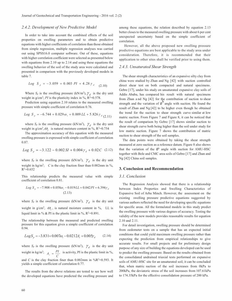
2.4.2. Development of New Predictive Model
In order to take into account the combined effects of the soil
properties on swelling parameters and to obtain predictive
equations with higher coefficients of correlation than those obtained
from simple regression, multiple regression analyses was carried
out using SPSS16.0 computer software. Out of these, equations
with higher correlation coefficient were selected as presented below
with equations from 2.10 up to 2.14 and using these equations the
swelling behavior of the soil of the study area were calculated and
presented in comparison with the previously developed models in
table 7.
dp PISLog 28.4003.0059.3 (2.10)
Where Sp is the swelling pressure (kN/m2), d is the dry unit
weight in g/cm3; PI is the plasticity index in %, R2=0.578.
Prediction using equation 2.10 relates to the measured swelling
pressure with simple coefficient of correlation 0.76.
dip LLSLog 826.5009.0029.0744.6(2.11)
where Sp is the swelling pressure (kN/m2), d is the dry unit
weight in g/cm3, i is natural moisture content in %, R2=0.754
The approximation accuracy of this equation with the measured
swelling pressure is expressed with simple coefficient of correlation
0.87.
CSISLog dp 02.0004.0002.0122.3 (2.12)
where Sp is the swelling pressure (kN/m2), d is the dry unit
weight in kg/m3; C is the clay fraction finer than 0.002mm in %, R2=0.652
This relationship predicts the measured value with simple coefficient of correlation 0.81.
dip PILLSLog 394.6042.0019.0058.0908.7
(2.13)
where Sp is the swelling pressure (kN/m2), d is the dry unit
weight in g/cm3, i , is natural moisture content in %, LL is
liquid limit in % & PI is the plastic limit in %, R2=0.891.
The relationship between the measured and predicted swelling pressure for this equation gives a simple coefficient of correlation 0.94.
dcip ASLog 005.00212.0007.0831.3 (2.14)
where Sp is the swelling pressure (kN/m2), d is the dry unit
weight in kg/m3; C
PIAc
is activity, PI is the plastic limit in %,
and C is the clay fraction finer than 0.002mm in %R2=0.593. It yields a simple coefficient of correlation 0.77.
The results from the above relations are tested to see how well
the developed equations have predicted the swelling pressure and
among these equations, the relation described by equation 2.13
better closes to the measured swelling pressure with about 6 per cent
unexpected uncertainty based on the simple coefficient of
correlation.
However, all the above proposed new swelling pressure
predictive equations are best applicable to the study area under
consideration. Therefore, it is recommended that their
application to other sites shall be verified prior to using them.
2.4.3. Unsaturated Shear Strength
The shear strength characteristics of an expansive silty clay from
china were studied by Zhan and Ng [42] with suction controlled
direct shear test on both compacted and natural specimens.
Gebre [17], under his study on unsaturated expansive clay soils of
Addis Ababa, has compared his result with natural specimens
from Zhan a nd Ng [42] for the contribution of suction to shear
strength and the variation of b
angle with suction. He found the
result of Zhan and Ng [42] to be higher even though he obtained
the trend for the suction to shear strength curve similar at low
matric suction. From Figure 7 and Figure 8, it can be noticed that
the result of comparison by Gebre [17] shows similar suction to
shear strength curve both being higher than the soil under study for
low matric suction. Figure 7 shows the contribution of matric
suction to shear strength of the soil samples.
The data points were obtained by taking the shear strength
measured at zero suction as a reference datum. Figure 8 also shows
that the variation of the b angle with suction for AMU-HSC
together with Bole and CMC area soils of Gebre [17] and Zhan and
Ng [42] China soil samples.
3. Conclusion and Recommendation
3.1. Conclusion
The Regression Analysis showed that there is a relationship
between Index Properties and Swelling Characteristics of
Expansive Soil of Arba Minch. However, the assessment on the
existing swelling pressure predictive equations suggested by
various authors reflected the need for developing specific equations
for specific areas. All the formulated models in this study predict
the swelling pressure with various degrees of accuracy. Testing the
validity of the new models provides reasonable results for equation
2.10 and 2.11.
For detail investigation, swelling pressure should be determined
from oedometer tests on a sample that has an expected initial
conditions that could yield maximum swelling pressure rather than
expecting the prediction from empirical relationships to give
accurate results. For small projects and for preliminary design
purpose of any size of building the equations developed can be used
to predict the swelling pressure. Based on the results obtained from
the consolidated undrained triaxial tests performed on expansive
soils of AMU-HSC site for an unsaturated soil, it can be concluded
that, when matric suction of the soil increases from 0kPa to
200kPa, the deviatoric stress of the soil increases from 107.61kPa
to 174.35kPa for the effective consolidation pressure of 200 kPa.

61
Uge
Table 7. Comparison of previously developed swell prediction equations with measured values and newly developed predictive model.
Previously Developed Swell Prediction Equations Predicted by the new models
Location
Dep
th o
f
Sa
mp
ling (m
)
Mea
sured
Sw
elling
Pressu
re (kP
a)
Pro
posed
Eq
n. b
y
Da
gm
aw
e
Nig
ussie (k
Pa)
Pro
posed
Eq
n.
by
Dan
iel Tek
lu
(kP
a)
Pro
posed
Eq
n.
by
Vija
yv
ergiy
a
an
d G
hazz
aly
(kP
a)
Pro
posed
Eq
n.
by
Nay
ak
an
d
Ch
ristense
n
(kP
a)
Pro
posed
Eq
n.
by
Kom
orn
ik
an
d D
av
id
(kP
a)
Usin
g E
qu
atio
n
2.1
0 (k
Pa
)
Usin
g E
qu
atio
n
2.11
(kP
a)
Usin
g E
qu
atio
n
2.1
2 (k
Pa
)
Usin
g E
qu
atio
n
2.1
3 (k
Pa
)
Usin
g E
qu
atio
n
2.1
4 (k
Pa
)
AMU–HSC 2.5 265.17 329.35 250.26 140.77 679.92 134.32 247.01 266.83 220.72 474.26 283.13 172.49
Yetnebersh 2.0 571.29 259.61 650.76 701.38 460.87 109.59 113.88 527.53 674.78 1581.69
667.41 576.43
Muluwengel 2.0 246.60 288.58 408.25 322.74 138.85 68.84 63.42 369.56 320.83 633.37 276.62 380.34
Edgetber Kebele
2.0 494.77 257.80 586.95 543.63 464.05 106.38 132.58 491.18 531.54 1034.71
625.09 456.55
Doysa Kebele
2.0 464.90 437.18 571.78 406.40 2143.94 235.77 482.42 492.75 515.37 1489.70
464.56 370.64
Wubete Hotel
1.5 250.15 411.49 220.42 138.29 124.30 107.19 68.19 236.98 178.13 748.20 231.09 226.28
Mesgid 1.0 74.53 202.04 109.54 76.18 137.74 58.62 56.67 141.64 159.66 247.38 148.20 129.77
Woreda Firdbet
1.5 481.77 216.00 339.59 318.41 329.99 90.81 94.52 328.09 401.23 777.79 533.90 314.93
Shecha highschool
1.5 458.28 188.62 189.47 185.27 163.60 75.06 50.57 211.99 293.72 643.78 402.03 232.38
Chamo Kebele
1.5 224.37 261.64 139.50 106.21 139.77 70.63 53.92 168.47 200.90 481.17 153.34 183.97
Figure 7. Contribution of suction to shear strength for AMU-HSC site together with Bole and CMC area soils of Gebre (2010) and
China soils of Zhan and Ng (2006)
Figure 8. Variations of b angles with matric suction for AMU-HSC together with Bole and CMC area soils of Gebre (2010) and
China soils of Zhan and Ng (2006)
The shape of the stress-strain curve is kept unaltered for the raise
in matric suction. Furthermore, as the matric suction of the soil
increases, the shear strength of the soil increases nonlinearly for the
applied matric suction ranges (i.e., 100kPa to 200kPa). However,
the rates of increase in the apparent shear strength due to increase
in matric suction, as expressed by the angle shows to decrease.
4. Recommendation
Although it is not expected to have an accurate swelling
pressure result from empirical equation, an improved model can
be fitted by increasing the database from tests done on a number
of undisturbed samples during driest season. For preliminary
estimation of the swelling characteristics of the study area, the
formulated equations can be utilized. In addition, their application
to other soils shall be carefully checked for their suitability before
utilizing partly and/or as a whole.
Further detail investigation on the unsaturated state can be
carried out by taking more number of samples and conducting the
test on matric suctions out of the limit used (i.e., lower than 100kPa
and higher than 200kPa) in order to see the effect. The
nonlinearity of the shear stress versus matric suction becomes
more noticeable when soils are being tested over a wider range of
matric suctions.
0
20
40
60
80
100
0 50 100 150 200 250
Con
trib
uti
on
of
suct
ion
to s
hea
r st
ren
gth
(k
Pa)
Matric suction (kPa)
Soil from China (Zhan and Ng)
Soil from CMC (Gebre)
Soil from Bole (Gebre)
Soil from AMU-HSC
0
5
10
15
20
25
30
0 50 100 150 200
, an
gle
(d
egre
e)
Matric suction (kPa)
Soil from China (Zhan and Ng)
Soil from CMC (Gebre)
Soil from Bole (Gebre)
Soil from AMU-HSC

62
Journal of Geotechnical and Transportation Engineering - 2016 vol. 2 (2)
References
[1] Abed, A. (2008). Numerical Modelling of Expansive Soil Behavior. Ph.D. Dissertation, Institut für Geotechnik, Universität Stuttgart, Germany.
[2] Alla P. (2009). Dynamic behavior of unsaturated soils. Msc. Thesis, Graduate Faculty of the Louisiana State University, U.S.A.
[3] Al-Rawas, A.A. and Goosen, M.F. (2006). Expansive soils: Recent advances in characterization and treatment. Taylor & Francis Group, London, UK.
[4] ASTM. (2004). Standard Test Method for soil and rock. Annual Book of ASTM Standards, Philadelphia, U.S.A.
[5] Ayteken, M. (1992). Finite Element Modeling of Lateral Swelling Pressure Distributions behind Earth Retaining Structures. Ph.D. Dissertation, Texas Tech University, U.S.A.
[6] Belachew, A (2000). Dry-spell analysis for studying the sustainability of rain-fed agriculture in Ethiopia: the case of the Arba Minch area. 8
th Nile 2002 Conference, Addis
Ababa, Ethiopia. [7] Blight, G. E. (1997). Mechanics of Residual Soils. A.A
Balkema, Rotterdam, Netherlands. [8] British Standards Institution, (1990). British standard
methods of test for soils for civil engineering purposes. British Standards Institution, London.
[9] Budhu, M. (2007). Soil Mechanics and Foundations.2nd
ed., John Wiley & Sons Inc., New York. [10] Chakraborty, S. (2009). Numerical Modeling for Long Term
Performance of Soil-Bentonite Cut- Off Walls in Unsaturated Soil Zone. Msc. Thesis, Graduate Faculty of the Louisiana State University, U.S.A.
[11] Chen, F.H.(1988). Foundation on Expansive Soils. Elsevier scientific publishing company. Craig, R.F.(2004). Craig’s Soil Mechanics. 7th ed., Spon Press, London and New York.
[12] CSA. (2007). The 2007 Population and Housing Census of Ethiopia: Statistical Report for Southern Nations, Nationalities and Peoples’ Region; Part I: Population Size and Characteristics. http://www.csa.gov.et 4/26/2011.
[13] Das, B. M. (2002). Principles of Geotechnical Engineering. 5th ed., Thomson Learning, U.S.A.
[14] Field, A. (2005). Discovering Statistics using SPSS. 2nd ed., SAGE publications, London.
[15] Förch, G. (2009). CICD Series Vol.3: Summary of Master Theses from Arba Minch University, Ethiopia. Printing Office, Universität Siegen, Germany.
[16] Fredlund, D.G. and Rahardjo, H.(1993). Soil Mechanics for Unsaturated Soils. John Wiley & Sons Inc. New York.
[17] Gebre, H. (2010). Unsaturated Shear Strength Characteristics and Stress Strain Behavior Of Expansive Soils of Addis Ababa. Msc. Thesis, Addis Ababa University, Addis Ababa, Ethiopia.
[18] Gebrehiwot, T. (2003). Ameliorated Design and Construction Techniques of Pavements on Expansive Soils. Msc. Thesis, Addis Ababa University, Addis Ababa, Ethiopia.
[19] Hilf, J.W. (1956). An Investigation of pore-water pressure in compacted cohesive soils. Ph.D. Dissertation, Texas Tech University, Texas.
[20] The Variation of Swelling Characteristics with EPS Geofoam in Expansive Soils. 18
th European Young Geotechnical
Engineers’ Conference, Portonovo, Ancona, Italy. [21] Kerry Rowe, R. (2001). Geotechnical and
Geoenvironmental Engineering Hand Book. Kulwer Academic Publishers, USA.
[22] Komornik, J. and David, A.(1969). Prediction of swelling potential for compacted clays. Journal of the Soil
Mechanics and Foundation Engineering Division, ASCE, Vol. 95, No. 1, 209–225.
[23] Legesse, M. (2004). Investigating Index Property of Expansive Soil of Ethiopia. Msc Thesis, Addis Ababa University, Addis Ababa, Ethiopia.
[24] Lu, N. and Likos, W.J. (2004). Unsaturated soil Mechanics. John Wiley & Sons Inc. New Jersey.
[25] Murray, H.H. (2007). Applied Clay Mineralogy: Occurrences, Processing and Application of Kaoines, Bentonites, Palygorskite-Sepiolite, and Common Clays. Elsevier scientific publishing company.
[26] Nayak, N.V. and Christensen, R.W.(1974). Swelling characteristics of compacted expansive soils. Clays and Clay Minerals, Vol. 19, No. 4, 251–261. Nelson, J.D. and Miller, D.J. (1992). Expansive Soils: Problems and Practice in Foundation and Pavement Engineering. New York: Wiley Interscience.
[27] Nigussie D. (2007). Indepth Investigation of Relationship between Index Property and Swelling Characteristics of Expansive soil in Bahir Dar. Msc. Thesis, Addis Ababa University, Addis Ababa, Ethiopia.
[28] Advanced unsaturated soil Mechanics and Engineering. Taylor &Francis Group, London and New York.
[29] Sabtan, A. A., (2005). Geotechnical properties of expansive clay shale in Tabuk, Saudi Arabia. Journal of Asian Earth Sciences 25, 747 -757, Elsevier scientific publishing company.
[30] Sisay A. (2004). Assessment of Damage of Buildings constructed in Expansive soil areas of Addis Ababa. Msc Thesis, Addis Ababa University Technology Faculty, Addis Ababa, Ethiopia.
[31] Sime, A., (2006). Further Investigation of Road Failures Constructed on Expansive Soils of Central Ethiopia: Addis Ababa –Jimma Road as a case Study. Msc. Thesis, Addis Ababa University, Addis Ababa, Ethiopia.
[32] Stephen G. F., Donald A.C., and Paul F.W.(2005). The shrink Swell Test. Geotechnical Testing Journal, Vol. 28, No.1.
[33] Teferra, A. (2009). Principles of Foundation Engineering. 2nd
ed. Addis Ababa University Press, Addis Ababa. [34] Teferra, A. And Leikun, M. (1999). Soil Mechanics. Addis
Ababa University press. Addis Ababa. [35] Teklu, D. (2003). Examining the swelling pressure of Addis
Ababa Expansive soil. Msc Thesis, Addis Ababa University Technology Faculty, Addis Ababa, Ethiopia.
[36] Theoretical soil mechanics. Wiley Publications, New York.
[37] Tilahun, D. (2004). Influence of Drainage Condition on Shear Strength Parameters of Expansive soils. Msc Thesis, Addis Ababa University Technology Faculty, Addis Ababa, Ethiopia.
[38] Ulusay R. (2002). A simple test and predictive models for assessing swell potential of Ankara (Turkey) Clay. Elsevier scientific publishing company.
[39] Prediction of swelling potential for natural clays. Proceedings of 3
rd
International Conference on Expansive Soils, Haifa, Israel, Vol. 1, 227–236.
[40] W/Medhin G., (2010). A Study on Shear Strength Characteristics of Addis Ababa Red Clay Soil for Unsaturated Case. Msc Thesis, Addis Ababa University, Addis Ababa, Ethiopia.
[41] Zewdie, A. (2004). Investigation into shear strength characteristics of Expansive soil of Ethiopia. Msc Thesis, Addis Ababa University, Addis Ababa, Ethiopia.