Embed Size (px)
Citation preview
Guo, D., et al.: Investigation on Steady and Unsteady Performance of a SCO2 ... THERMAL SCIENCE: Year 2017, Vol. 21, Suppl. 1, pp. S185-S192 S185
INVESTIGATION ON STEADY AND UNSTEADY PERFORMANCE OF A SCO2 CENTRIFUGAL COMPRESSOR WITH SPLITTERS
by
Ding GUO, Dongbo SHI, and Di ZHANG*
MOE Key Laboratory of Thermo-Fluid Science and Engineering, School of Energy and Power Engineering, Xi’an Jiaotong University, Xi’an, China
Original scientific paper https://doi.org/10.2298/TSCI17S1185G
Supercritical carbon dioxide (SCO2 ) is widely concerned with its excellent physical properties. Its high density helps to achieve a compact mechanical structure, espe-cially in all kinds of turbomachinery. In this paper, a SCO2 centrifugal compressor with splitter blades is displayed and numerically investigated. A thorough numerical analysis of the steady and unsteady performance of this SCO2 centrifugal compres-sor is performed in ANSYS-CFX with SST turbulence model. Streamlines, pressure and temperature under steady- and unsteady-state are compared and analyzed. Moreover, the trans-critical phenomenon at the leading edge of the rotor blade and the aerodynamic performance are covered. The results in this paper provide the foun-dation for the design and numerical investigation of SCO2 centrifugal compressors.Key words: SCO2, centrifugal compressor, unsteady flow, numerical simulation
Introduction
Supercritical SCO2 is a kind of supercritical fluid which has a critical point at around room temperature. Concretely, its critical temperature and pressure are, respectively, 304.2 K and 7.4 MPa [1]. The CO2 has high density like fluid, low viscosity like gas and low surface tension and has good flow, penetration and transfer performance under supercritical condition [2-4]. The research on SCO2 has gradually been increasing lately. In recent years, the investiga-tions on SCO2 Brayton cycle or SCO2-based solar Rankine cycle system have been covered [5]. As a thermodynamic cycle refrigerant, supercritical CO2 makes it possible to take advantage of the characteristics of the high density near the critical point, reduce the compression power of the whole cycle [6] and improve cycle efficiency.
Based on the special characteristics of SCO2, some scholars have carried out theoretical analysis, numerical simulation, and experimental research on the design, parameter optimization and efficiency of SCO2 centrifugal compressor. Budinis and Thornhill [7] studied the comput-er-based design and analysis of control systems for centrifugal compressors when the operating fluid is supercritical CO2. Pecnik et al. [8] used the Spalart-Allmaras (S-A) model and two equa-tion k-ω SST turbulence model to carry out the numerical analysis of the radial-flow SCO2 com-pressor, and compared the numerical results with the SCO2 compression cycle test data of Sandia National Laboratories, Albuquerque, N. Mex., USA. Behafarid and Podowski [9] presented a novel modeling approach and the corresponding computer simulation of the SCO2 flow inside a high-speed compact centrifugal compressor. Compared to normal CO2, the centrifugal compres-
* Corresponding author, e-mail: [email protected]
Guo, D., et al.: Investigation on Steady and Unsteady Performance of a SCO2 ... S186 THERMAL SCIENCE: Year 2017, Vol. 21, Suppl. 1, pp. S185-S192
sor with SCO2 has higher efficiency, a more compact mechanical structure, and a larger pressure ratio [10]. Hence, the work in this paper is of great importance for future power systems.
Based on the current research, this paper aims at a 5 MW SCO2 centrifugal compres-sor with splitter blades and conducts the steady and unsteady simulation in ANSYS-CFX. Af-terwards, the flow characteristics and performance are analyzed and compared in detail, which provide the theoretical foundation for SCO2 centrifugal compressors in engineering research.
Numerical methods
Boundary conditions
Here, the working fluid is SCO2, and the physical parameters are the same with CO2RK in the MATERIAL-redkw database in ANSYS-CFX 15.0. The database is based on the Redlich Kwong equation, and provides a variety of amendments. Kim et al. [11] estimate the error between the real properties obtained from the NIST REFPROP and the ones calculated within the CFX code to verify the reliability of the CO2RK. The boundary conditions of mass, flow and temperature are given in the rotor fluid flow field, the inlet flow rate is 273.1 kg/s, and the inlet temperature is 306.7 K. Besides, the rotor fluid flow field is set around the Z-axis with a rotational speed of 15000 rpm. The diffuser fluid flow field is set as the pressure outlet boundary condition, and the outlet pressure is 18.8 MPa. Meanwhile, the wall surface of the diffuser is set as an absolutely stationary wall, and the wall of the rotor impeller is set as a relatively stationary wall, and the upper and the lower walls of all the regions are adiabatic walls, which can meet the requirements of non-slip flow conditions.
A turbulence model
The SST k-ω turbulence model is adopted in this paper, which was proposed by Men-ter [12] based on the k-ω and k-ω turbulence model. This model combines the advantages of the k-ω turbulence model and k-ω turbulence model. It not only overcomes the limitations of k-ω turbulence model to simulate the wall region of low Reynolds number, but also overcomes the disadvantage that the k-ω turbulence model has a high requirement for grid quality, so it is efficient and accurate to simulate turbulent flow. Some other scholars [13] have also used this turbulence model in the analysis of centrifugal compressor, and obtained reasonable results. The transport equation for this model is as follows.
The k and ω equations are [12, 13]:
( ) ( )( )
∂ ∂ ∂ ∂′+ = − + + ∂ ∂ ∂ ∂
jk k t
j j j
kuk kP kt x x x
ρρβ ρ ω µ σ µ (1)
( ) ( )( ) ( )2
1 21 12 1
∂ ∂ ∂ ∂ ∂ ∂′+ = − + + + − ∂ ∂ ∂ ∂ ∂ ∂
jk t
j t j j j j
u kP k Ft x v x x x xω ω
ρωρω ω ωα β ρ ω µ σ µ ρσω
(2)
respectively, where α , ′β , and 2ωσ are constants, ρ – the density, ju – the velocity, k – the turbu-lent kinetic energy, ω – the specific dissipation rate, tµ – the dynamic viscosity, tν – the kinemat-ic viscosity, kP – the pressure, and 1F – the weighting function.
Generation of mesh
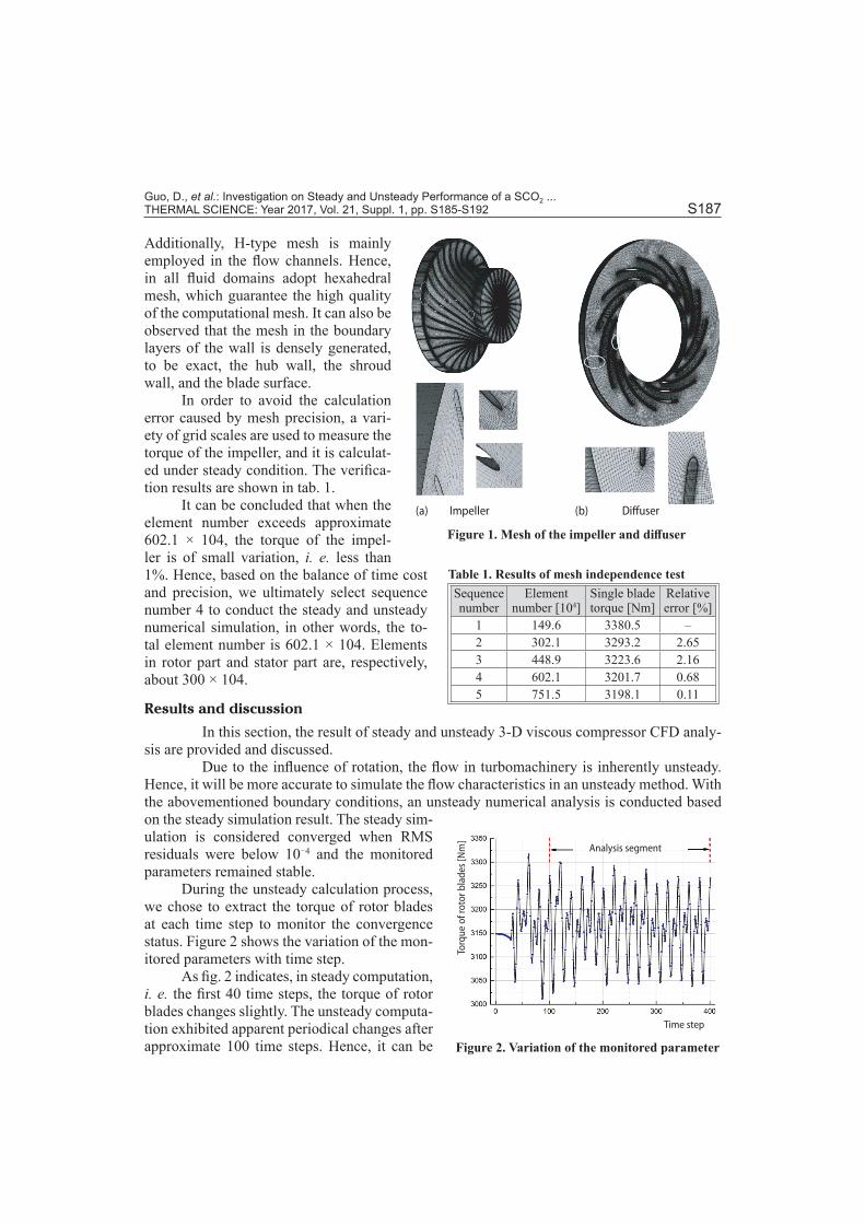
As shown in fig. 1, O-type mesh is applied around impeller and diffuser blades, which greatly improved the mesh quality at the leading edge (LE) and the trailing edge of the blades.
Guo, D., et al.: Investigation on Steady and Unsteady Performance of a SCO2 ... THERMAL SCIENCE: Year 2017, Vol. 21, Suppl. 1, pp. S185-S192 S187
Additionally, H-type mesh is mainly employed in the flow channels. Hence, in all fluid domains adopt hexahedral mesh, which guarantee the high quality of the computational mesh. It can also be observed that the mesh in the boundary layers of the wall is densely generated, to be exact, the hub wall, the shroud wall, and the blade surface.
In order to avoid the calculation error caused by mesh precision, a vari-ety of grid scales are used to measure the torque of the impeller, and it is calculat-ed under steady condition. The verifica-tion results are shown in tab. 1.
It can be concluded that when the element number exceeds approximate 602.1 × 10⁴, the torque of the impel-ler is of small variation, i. e. less than 1%. Hence, based on the balance of time cost and precision, we ultimately select sequence number 4 to conduct the steady and unsteady numerical simulation, in other words, the to-tal element number is 602.1 × 10⁴. Elements in rotor part and stator part are, respectively, about 300 × 104.
Results and discussion
In this section, the result of steady and unsteady 3-D viscous compressor CFD analy-sis are provided and discussed.
Due to the influence of rotation, the flow in turbomachinery is inherently unsteady. Hence, it will be more accurate to simulate the flow characteristics in an unsteady method. With the abovementioned boundary conditions, an unsteady numerical analysis is conducted based on the steady simulation result. The steady sim-ulation is considered converged when RMS residuals were below 10−4 and the monitored parameters remained stable.
During the unsteady calculation process, we chose to extract the torque of rotor blades at each time step to monitor the convergence status. Figure 2 shows the variation of the mon-itored parameters with time step.
As fig. 2 indicates, in steady computation, i. e. the first 40 time steps, the torque of rotor blades changes slightly. The unsteady computa-tion exhibited apparent periodical changes after approximate 100 time steps. Hence, it can be
Table 1. Results of mesh independence testSequence number
Element number [104]
Single blade torque [Nm]
Relative error [%]
1 149.6 3380.5 –2 302.1 3293.2 2.653 448.9 3223.6 2.164 602.1 3201.7 0.685 751.5 3198.1 0.11
Analysis segment
Torq
ue o
f rot
or b
lade
s [N
m]
Time step
Figure 2. Variation of the monitored parameter
(a) (b) Impeller Diffuser
Figure 1. Mesh of the impeller and diffuser
Guo, D., et al.: Investigation on Steady and Unsteady Performance of a SCO2 ... S188 THERMAL SCIENCE: Year 2017, Vol. 21, Suppl. 1, pp. S185-S192
concluded that the unsteady calculation reached convergence criterion. To run the analysis that will be mentioned later, we have chosen one revolution of impeller as the analysis segment, as shown in fig. 2 (i. e., 300 time steps).
Steady and unsteady flow phenomenon
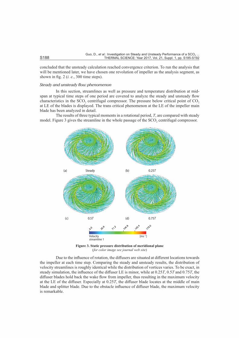
In this section, streamlines as well as pressure and temperature distribution at mid-span at typical time steps of one period are covered to analyze the steady and unsteady flow characteristics in the SCO2 centrifugal compressor. The pressure below critical point of CO2 at LE of the blades is displayed. The trans critical phenomenon at the LE of the impeller main blade has been analyzed in detail.
The results of three typical moments in a rotational period, T, are compared with steady model. Figure 3 gives the streamline in the whole passage of the SCO2 centrifugal compressor.
(a) Steady (b) 0.25T
(c) 0.5T (d) 0.75T
[ms−1]Velocitystreamline 1
Figure 3. Static pressure distribution of meridional plane (for color image see journal web site)
Due to the influence of rotation, the diffusers are situated at different locations towards the impeller at each time step. Comparing the steady and unsteady results, the distribution of velocity streamlines is roughly identical while the distribution of vortices varies. To be exact, in steady simulation, the influence of the diffuser LE is minor, while at 0.25T, 0.5T and 0.75T, the diffuser blades hold back the wake flow from impeller, thus resulting in the maximum velocity at the LE of the diffuser. Especially at 0.25T, the diffuser blade locates at the middle of main blade and splitter blade. Due to the obstacle influence of diffuser blade, the maximum velocity is remarkable.
Guo, D., et al.: Investigation on Steady and Unsteady Performance of a SCO2 ... THERMAL SCIENCE: Year 2017, Vol. 21, Suppl. 1, pp. S185-S192 S189
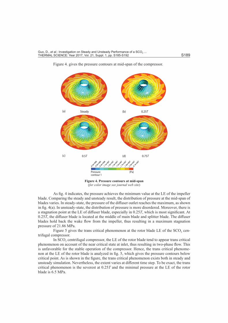
Figure 4. gives the pressure contours at mid-span of the compressor.
(a) Steady (b) 0.25T
(c) 0.5T (d) 0.75T
[Pa]Pressurecontour 1
Figure 4. Pressure contours at mid-span (for color image see journal web site)
As fig. 4 indicates, the pressure achieves the minimum value at the LE of the impeller blade. Comparing the steady and unsteady result, the distribution of pressure at the mid-span of blades varies. In steady-state, the pressure of the diffuser outlet reaches the maximum, as shown in fig. 4(a). In unsteady-state, the distribution of pressure is more disordered. Moreover, there is a stagnation point at the LE of diffuser blade, especially in 0.25T, which is most significant. At 0.25T, the diffuser blade is located at the middle of main blade and splitter blade. The diffuser blades hold back the wake flow from the impeller, thus resulting in a maximum stagnation pressure of 21.86 MPa.
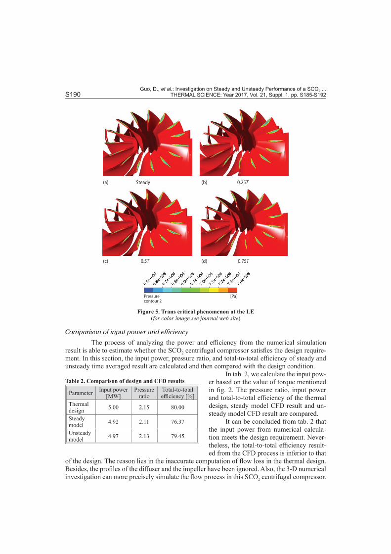
Figure 5 gives the trans critical phenomenon at the rotor blade LE of the SCO2 cen-trifugal compressor.
In SCO2 centrifugal compressor, the LE of the rotor blade tend to appear trans critical phenomenon on account of the near critical state at inlet, thus resulting in two-phase flow. This is unfavorable for the stable operation of the compressor. Hence, the trans critical phenome-non at the LE of the rotor blade is analyzed in fig. 5, which gives the pressure contours below critical point. As is shown in the figure, the trans critical phenomenon exists both in steady and unsteady simulation. Nevertheless, the extent varies at different time step. To be exact, the trans critical phenomenon is the severest at 0.25T and the minimal pressure at the LE of the rotor blade is 6.5 MPa.
Guo, D., et al.: Investigation on Steady and Unsteady Performance of a SCO2 ... S190 THERMAL SCIENCE: Year 2017, Vol. 21, Suppl. 1, pp. S185-S192
Comparison of input power and efficiency
The process of analyzing the power and efficiency from the numerical simulation result is able to estimate whether the SCO2 centrifugal compressor satisfies the design require-ment. In this section, the input power, pressure ratio, and total-to-total efficiency of steady and unsteady time averaged result are calculated and then compared with the design condition.
In tab. 2, we calculate the input pow-er based on the value of torque mentioned in fig. 2. The pressure ratio, input power and total-to-total efficiency of the thermal design, steady model CFD result and un-steady model CFD result are compared.
It can be concluded from tab. 2 that the input power from numerical calcula-tion meets the design requirement. Never-theless, the total-to-total efficiency result-ed from the CFD process is inferior to that
of the design. The reason lies in the inaccurate computation of flow loss in the thermal design. Besides, the profiles of the diffuser and the impeller have been ignored. Also, the 3-D numerical investigation can more precisely simulate the flow process in this SCO2 centrifugal compressor.
(a) Steady (b) 0.25T
(c) 0.5T (d) 0.75T
[Pa]Pressurecontour 2
Figure 5. Trans critical phenomenon at the LE (for color image see journal web site)
Table 2. Comparison of design and CFD results
Parameter Input power [MW]
Pressure ratio
Total-to-total efficiency [%]
Thermal design 5.00 2.15 80.00
Steady model 4.92 2.11 76.37
Unsteady model 4.97 2.13 79.45
Guo, D., et al.: Investigation on Steady and Unsteady Performance of a SCO2 ... THERMAL SCIENCE: Year 2017, Vol. 21, Suppl. 1, pp. S185-S192 S191
Comparing steady and unsteady model, we can conclude that the result of unsteady simulation is more close to the thermal design. Hence, it is more precise to use an unsteady model in CFD process, which has taken the influence of rotation into account.
Conclusions
In this paper, a SCO2 centrifugal compressor with splitter blades is displayed and numerically investigated. A thoroughly numerical analysis of the steady and unsteady perfor-mance of this SCO2 centrifugal compressor is performed in ANSYS-CFX. The computation adopts hexahedral mesh and SST turbulence model.
Streamlines, pressure and temperature distribution under steady- and unsteady-state are compared and analyzed. In the meantime, the trans critical phenomenon at the leading edge of the rotor blade is covered. The result in steady computation is obviously different from the unsteady simulation. Due to the influence of rotation, the diffusers are situated at different lo-cations towards the impeller at each time step. Hence, the distribution of the parameters varies at each time step. The unsteady flow characteristics are prominent in the SCO2 centrifugal compressor.
The pressure ratio, input power, and total-to-total efficiency mainly meet the design requirement, although the efficiency was slightly lower in the 3-D CFD computation owing to the inaccurate calculation of flow loss in the thermal design. And comparing steady- and un-steady-state, the result of unsteady simulation is more close to the thermal design.
In conclusion, the unsteady flow characteristics are prominent in the SCO2 centrifugal compressor, and unsteady CFD simulation is able to provide a more accurate estimation of compressor performance. The results in this paper provide the foundation for the design and numerical investigation of SCO2 centrifugal compressors.
Acknowledgment
This work is funded by the Foundation of the Key Laboratory of Thermal Power Technology (TPL2016BA001).
Nomenclature
kP – pressure, [Pa]t – time co-ordinate, [m]uj – velocity, [ms–1]xj – space co-ordinates, [s]
Greek symbol
ρ – density, [kgm–3]
References[1] Gil, L., et al., Experimental Setup to Measure Critical Properties of Pure and Binary Mixtures and Their
Densities at Different Pressures and Temperatures Determination of the Precision and Uncertainty in the Results, J. Supercrit. Fluids, 44 (2008), 2, pp. 123-138
[2] Hemrann, H., et al., CO2 as Refrigerant-Possible Applications, Proceedings, 4th IIR-Gustav Lorenzten Conference on Natural Working Fluids, Purdue University, West Lafayette, Ind., USA, 2000, pp. 43-50
[3] Tanaka, H., et al., Forced Convection Heat Transfer to Fluid Near Critical Point Flowing in Circular Tube, Int. J. of Heat and Mass Transfer, 14 (1971), 6, pp. 7395-7400
[4] Brassington, D. J., et al., Measurements of Forced Convective Heat Transfer to Supercritical Helium, International Journal of Heat and Mass Transfer, 20 (1977), 3, pp. 207-214
[5] Ahn, Y., et al., Review of Supercritical CO2 Power Cycle Technology and Current Status of Research and Development, Nuclear Engineering & Technology, 47 (2015), 6, pp. 647-661
[6] Parma, E. J., et al., Supercritical CO2 Direct Cycle Gas Fast Reactor (SC-GFR) Concept, Proceedings, ASME 2011 Small Modular Reactors Symposium, Washington, D.C., USA, 2011, pp. 91-94
Guo, D., et al.: Investigation on Steady and Unsteady Performance of a SCO2 ... S192 THERMAL SCIENCE: Year 2017, Vol. 21, Suppl. 1, pp. S185-S192
[7] Budinis, S., Thornhill, N. F., Supercritical Fluid Recycle for Surge Control of CO2 Centrifugal Compres-sors, Comput. Chem. Eng, 91 (2016), Aug., pp. 329-342
[8] Pecnik, R., et al., Computational Fluid Dynamics of a Radial Compressor Operating with Supercritical CO2, ASME Journal of Engineering for Gas Turbines and Power, 134 (2012), 12, pp. 201-213
[9] Behafarid, F., Podowski, M. Z., Modeling and Computer Simulation of Centrifugal CO2 Compressors at Supercritical Pressures, J. Fluids Eng.-Trans. ASME, 138 (2016), 6, 061106
[10] Kimball, K. J., Clementoni, E. M, Supercritical Carbon Dioxide Brayton Power Cycle Development Overview, Proceedings, ASME Turbo Expo 2013: Turbine Technical Conference and Exposition, San Antonio, Tex., USA, 2013, pp. 931-940
[11] Kim, S. G., et al., CFD Investigation of a Centrifugal Compressor Derived from Pump Technology for Su-percritical Carbon Dioxide as a Working Fluid, Journal of Supercritical Fluids, 86 (2014), 1, pp. 160-171
[12] Menter, F. R., Two-Equation Eddy-Viscosity Turbulence Models for Engineering Applications, AIAA, 32 (1994), 8, pp. 1598-1605
[13] Mojaddam, M., et al., Experimental and Numerical Investigations of Radial Flow Compressor Compo-nent Losses, Journal of Mechanical Science and Technology, 28 (2014), 6, pp. 2189-2196
Paper submitted: March 8, 2017Paper revised: June 8, 2017Paper accepted: June 10, 2017
© 2017 Society of Thermal Engineers of SerbiaPublished by the Vinča Institute of Nuclear Sciences, Belgrade, Serbia.
This is an open access article distributed under the CC BY-NC-ND 4.0 terms and conditions