Embed Size (px)
Citation preview
ENGINEERING JOURNAL / FIRST QUARTER / 2017 / 21
INTRODUCTION
C astellated beams have been used since the 1940s (Zaar-our and Redwood, 1996) because of their ability to
offer wide and open spaces, reduce floor-to-floor heights, increase illumination, and improve aesthetic appeal. Engi-neering advantages of castellated beams include superior load deflection characteristics, higher strength and stiffness, lower weight, and the ability to span up to 90 ft without field splicing. Also, the automation process has reduced the cost of their fabrication to the level where, for certain applica-tions, they may be competitive with open-web steel joists (Zaarour and Redwood, 1996). Castellated beams have con-sisted typically of hexagonal or octagonal openings, with the octagonal openings made possible by the addition of incre-mental plates between the cut webs. Figure 1 illustrates an
application of castellated beams with hexagonal openings. Another similar form is the cellular beam, which consists of circular web openings. Cellular beams have gained popular-ity because of the aesthetic appeal they offer in architectur-ally exposed surfaces. Some manufacturers have recently developed new opening shapes for castellated beams. For example, ArcelorMittal presented castellated beams with sinusoidal web openings, called the Angelina Beam (Wang et al., 2014). Durif and Bouchair (2013) performed an exper-imental study on beams with such openings. Tsavdaridis and D’Mello (2011, 2012) investigated the behavior of castellated beams with novel, elliptically based web openings.
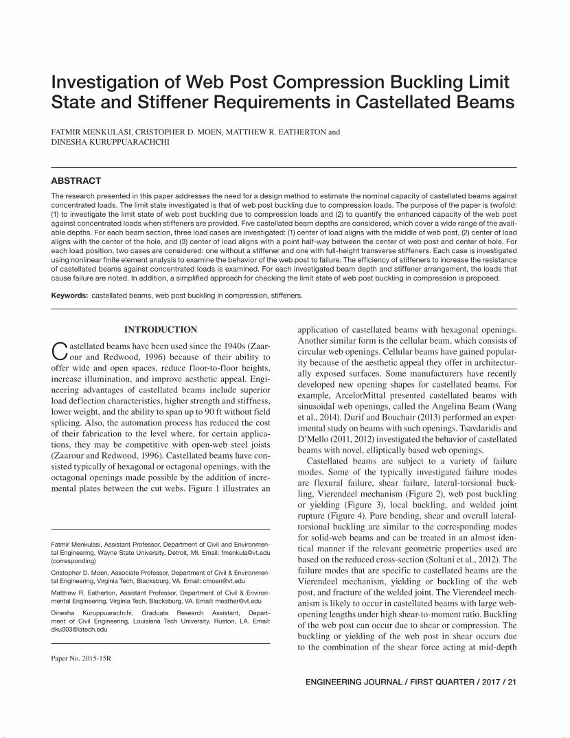
Castellated beams are subject to a variety of failure modes. Some of the typically investigated failure modes are flexural failure, shear failure, lateral-torsional buck-ling, Vierendeel mechanism (Figure 2), web post buckling or yielding (Figure 3), local buckling, and welded joint rupture (Figure 4). Pure bending, shear and overall lateral-torsional buckling are similar to the corresponding modes for solid-web beams and can be treated in an almost iden-tical manner if the relevant geometric properties used are based on the reduced cross-section (Soltani et al., 2012). The failure modes that are specific to castellated beams are the Vierendeel mechanism, yielding or buckling of the web post, and fracture of the welded joint. The Vierendeel mech-anism is likely to occur in castellated beams with large web-opening lengths under high shear-to-moment ratio. Buckling of the web post can occur due to shear or compression. The buckling or yielding of the web post in shear occurs due to the combination of the shear force acting at mid-depth
Investigation of Web Post Compression Buckling Limit State and Stiffener Requirements in Castellated BeamsFATMIR MENKULASI, CRISTOPHER D. MOEN, MATTHEW R. EATHERTON and DINESHA KURUPPUARACHCHI
ABSTRACT
The research presented in this paper addresses the need for a design method to estimate the nominal capacity of castellated beams against concentrated loads. The limit state investigated is that of web post buckling due to compression loads. The purpose of the paper is twofold: (1) to investigate the limit state of web post buckling due to compression loads and (2) to quantify the enhanced capacity of the web post against concentrated loads when stiffeners are provided. Five castellated beam depths are considered, which cover a wide range of the avail-able depths. For each beam section, three load cases are investigated: (1) center of load aligns with the middle of web post, (2) center of load aligns with the center of the hole, and (3) center of load aligns with a point half-way between the center of web post and center of hole. For each load position, two cases are considered: one without a stiffener and one with full-height transverse stiffeners. Each case is investigated using nonlinear finite element analysis to examine the behavior of the web post to failure. The efficiency of stiffeners to increase the resistance of castellated beams against concentrated loads is examined. For each investigated beam depth and stiffener arrangement, the loads that cause failure are noted. In addition, a simplified approach for checking the limit state of web post buckling in compression is proposed.
Keywords: castellated beams, web post buckling in compression, stiffeners.
Fatmir Menkulasi, Assistant Professor, Department of Civil and Environmen-tal Engineering, Wayne State University, Detroit, MI. Email: [email protected] (corresponding)
Cristopher D. Moen, Associate Professor, Department of Civil & Environmen-tal Engineering, Virginia Tech, Blacksburg, VA. Email: [email protected]
Matthew R. Eatherton, Assistant Professor, Department of Civil & Environ-mental Engineering, Virginia Tech, Blacksburg, VA. Email: [email protected]
Dinesha Kuruppuarachchi, Graduate Research Assistant, Depart-ment of Civil Engineering, Louisiana Tech University, Ruston, LA. Email: [email protected]
Paper No. 2015-15R
021-044_EJQ117_2015-15R.indd 21 12/6/16 5:01 PM
22 / ENGINEERING JOURNAL / FIRST QUARTER / 2017
of the web post with a double curvature bending moment over the height of the web post. The buckling of the web post in compression can occur when the web post is sub-ject to concentrated forces. The horizontal shear force can also cause the fracture of the welded joint in the web post, especially in cases when the length of the welded joint is small. Local buckling may occur in three ways in castellated beams: (1) buckling of the compression flange, (2) buckling of the T-section in compression and (3) vertical instability of the sides of the web openings in high shear zones. Ellobody (2011, 2012) reports that additional failure modes may occur independently or interact with each other.
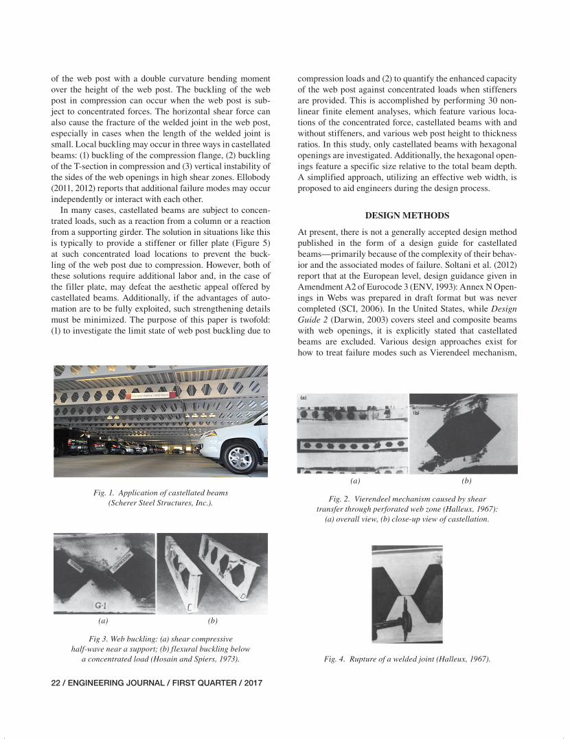
In many cases, castellated beams are subject to concen-trated loads, such as a reaction from a column or a reaction from a supporting girder. The solution in situations like this is typically to provide a stiffener or filler plate (Figure 5) at such concentrated load locations to prevent the buck-ling of the web post due to compression. However, both of these solutions require additional labor and, in the case of the filler plate, may defeat the aesthetic appeal offered by castellated beams. Additionally, if the advantages of auto-mation are to be fully exploited, such strengthening details must be minimized. The purpose of this paper is twofold: (1) to investigate the limit state of web post buckling due to
compression loads and (2) to quantify the enhanced capacity of the web post against concentrated loads when stiffeners are provided. This is accomplished by performing 30 non-linear finite element analyses, which feature various loca-tions of the concentrated force, castellated beams with and without stiffeners, and various web post height to thickness ratios. In this study, only castellated beams with hexagonal openings are investigated. Additionally, the hexagonal open-ings feature a specific size relative to the total beam depth. A simplified approach, utilizing an effective web width, is proposed to aid engineers during the design process.
DESIGN METHODS
At present, there is not a generally accepted design method published in the form of a design guide for castellated beams—primarily because of the complexity of their behav-ior and the associated modes of failure. Soltani et al. (2012) report that at the European level, design guidance given in Amendment A2 of Eurocode 3 (ENV, 1993): Annex N Open-ings in Webs was prepared in draft format but was never completed (SCI, 2006). In the United States, while Design Guide 2 (Darwin, 2003) covers steel and composite beams with web openings, it is explicitly stated that castellated beams are excluded. Various design approaches exist for how to treat failure modes such as Vierendeel mechanism,
Fig. 1. Application of castellated beams (Scherer Steel Structures, Inc.).
(a) (b)
Fig. 2. Vierendeel mechanism caused by shear transfer through perforated web zone (Halleux, 1967):
(a) overall view, (b) close-up view of castellation.
Fig. 4. Rupture of a welded joint (Halleux, 1967).
(a) (b)
Fig 3. Web buckling: (a) shear compressive half-wave near a support; (b) flexural buckling below
a concentrated load (Hosain and Spiers, 1973).
021-044_EJQ117_2015-15R.indd 22 12/6/16 5:01 PM
ENGINEERING JOURNAL / FIRST QUARTER / 2017 / 23
fracture of a welded joint, and web-post buckling due to the horizontal shear and bending moments. Soltani et al. (2012) provide a summary of these design methods and propose a numerical model to predict the behavior of castellated beams with hexagonal and octagonal openings up to failure. Tsavdaridis and D’Mello (2011, 2012) performed an optimi-zation study on perforated steel beams with various novel web-opening shapes through nonlinear finite element analy-ses and an investigation on the behavior of perforated steel beams with closely spaced web openings. Zaarour and Red-wood (1996) investigated the strength of castellated beams susceptible to web-post buckling due to horizontal shear and bending moments. Wang et al. (2014) examined the Vierend-eel mechanism failure of castellated beams with fillet corner web openings.
One of the studies that addresses the resistance of castel-lated beams against concentrated loads, in addition to the other modes of failure, is the one performed by Hosain and Spiers (1973), in which they tested 12 castellated beams with the objective of investigating the effect of hole geom-etry on the mode of failure and ultimate strength of such
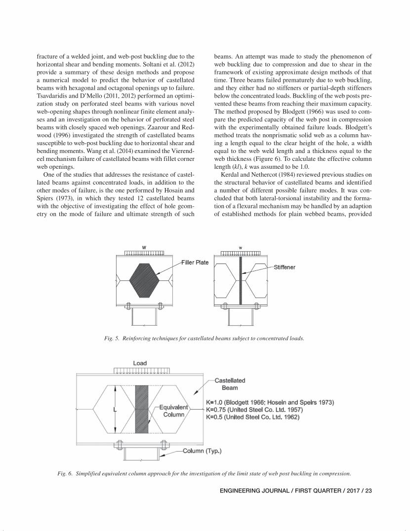
beams. An attempt was made to study the phenomenon of web buckling due to compression and due to shear in the framework of existing approximate design methods of that time. Three beams failed prematurely due to web buckling, and they either had no stiffeners or partial-depth stiffeners below the concentrated loads. Buckling of the web posts pre-vented these beams from reaching their maximum capacity. The method proposed by Blodgett (1966) was used to com-pare the predicted capacity of the web post in compression with the experimentally obtained failure loads. Blodgett’s method treats the nonprismatic solid web as a column hav-ing a length equal to the clear height of the hole, a width equal to the web weld length and a thickness equal to the web thickness (Figure 6). To calculate the effective column length (kl), k was assumed to be 1.0.
Kerdal and Nethercot (1984) reviewed previous studies on the structural behavior of castellated beams and identified a number of different possible failure modes. It was con-cluded that both lateral-torsional instability and the forma-tion of a flexural mechanism may be handled by an adaption of established methods for plain webbed beams, provided
Fig. 5. Reinforcing techniques for castellated beams subject to concentrated loads.
Fig. 6. Simplified equivalent column approach for the investigation of the limit state of web post buckling in compression.
021-044_EJQ117_2015-15R.indd 23 12/6/16 5:01 PM
24 / ENGINEERING JOURNAL / FIRST QUARTER / 2017
that the cross-sectional properties are those corresponding to the centerline of castellation. It was also concluded that the methods available at that time for the determination of collapse in the other modes, while rather less accurate, were adequate for design except in the case of web post buck-ling in compression. Kerdal and Nethercot state that while the web post could be considered to be a column having the depth of the hole and the area of the welded joint, there does not seem to be an agreement as to which effective length of the column to use. For example, an effective length factor of 0.75 was used in the study by the United Steel Co. Ltd. (1957). This was later (1962) reduced to 0.5 in a report by the same agency. Finally, Hosain and Spiers (1973) assumed the web posts to be pinned at both ends. Accordingly, one of the conclusions in the report by Kerdal and Nethercot is that no satisfactory method has been identified for the prediction of the load causing vertical buckling of the web post under a concentrated load or at a reaction point. As a result, this failure mode was reported as an area of uncertainty in the design of castellated beams, and there is a need to obtain a better idea as to what is the effective area of the column and its effective length.
In the light of this discussion, the investigation described in this paper was undertaken with the goal of investigating the capacity of castellated beams under concentrated loads using nonlinear finite element analysis and models that spe-cifically address this condition by isolating the beam sec-tions from the other modes of failure.
RESEARCH APPROACH
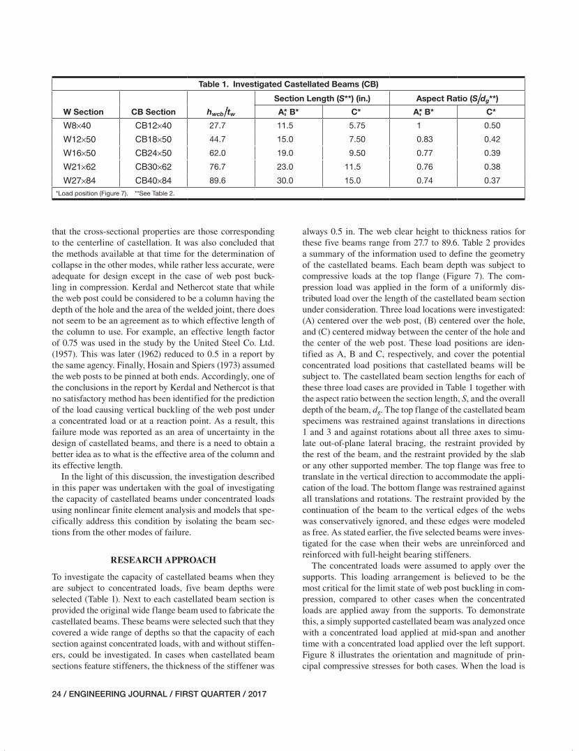
To investigate the capacity of castellated beams when they are subject to concentrated loads, five beam depths were selected (Table 1). Next to each castellated beam section is provided the original wide flange beam used to fabricate the castellated beams. These beams were selected such that they covered a wide range of depths so that the capacity of each section against concentrated loads, with and without stiffen-ers, could be investigated. In cases when castellated beam sections feature stiffeners, the thickness of the stiffener was
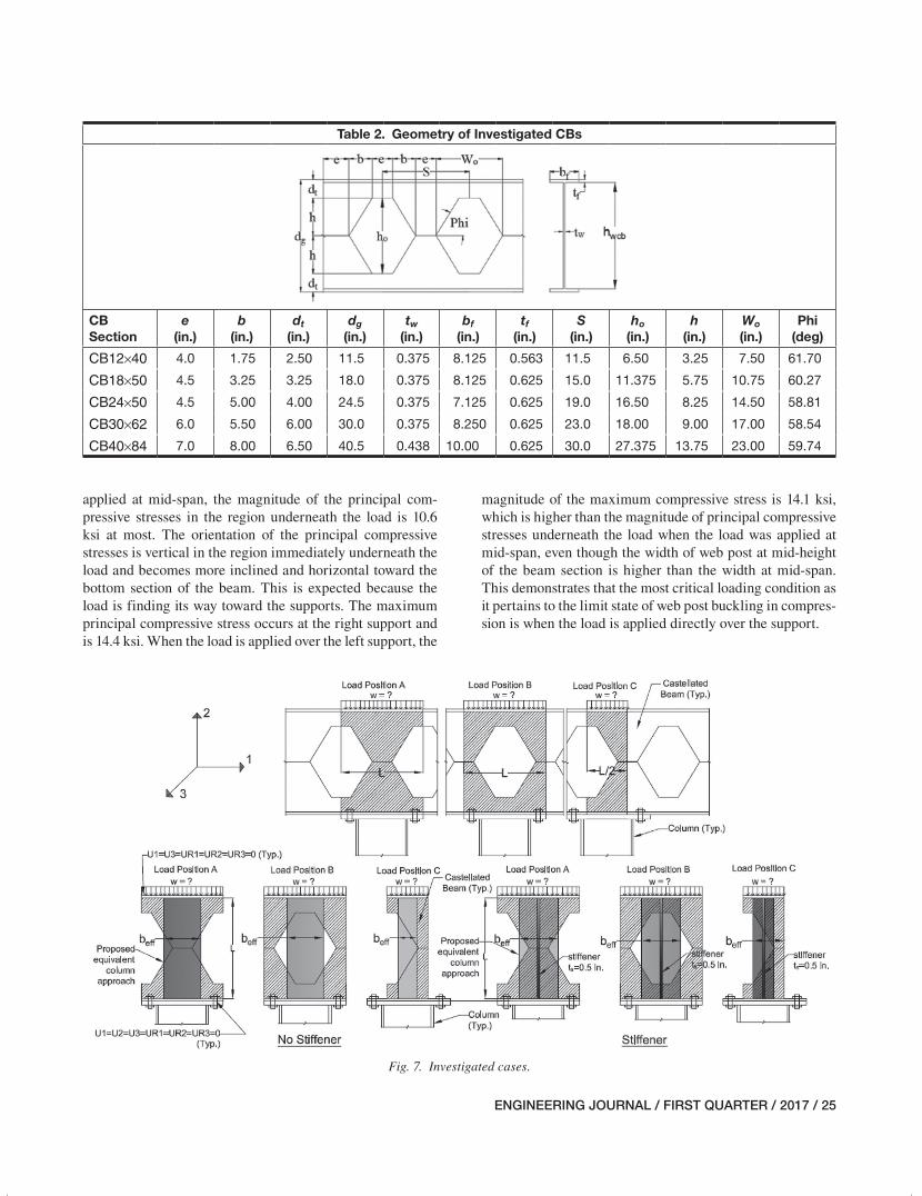
always 0.5 in. The web clear height to thickness ratios for these five beams range from 27.7 to 89.6. Table 2 provides a summary of the information used to define the geometry of the castellated beams. Each beam depth was subject to compressive loads at the top flange (Figure 7). The com-pression load was applied in the form of a uniformly dis-tributed load over the length of the castellated beam section under consideration. Three load locations were investigated: (A) centered over the web post, (B) centered over the hole, and (C) centered midway between the center of the hole and the center of the web post. These load positions are iden-tified as A, B and C, respectively, and cover the potential concentrated load positions that castellated beams will be subject to. The castellated beam section lengths for each of these three load cases are provided in Table 1 together with the aspect ratio between the section length, S, and the overall depth of the beam, dg. The top flange of the castellated beam specimens was restrained against translations in directions 1 and 3 and against rotations about all three axes to simu-late out-of-plane lateral bracing, the restraint provided by the rest of the beam, and the restraint provided by the slab or any other supported member. The top flange was free to translate in the vertical direction to accommodate the appli-cation of the load. The bottom flange was restrained against all translations and rotations. The restraint provided by the continuation of the beam to the vertical edges of the webs was conservatively ignored, and these edges were modeled as free. As stated earlier, the five selected beams were inves-tigated for the case when their webs are unreinforced and reinforced with full-height bearing stiffeners.
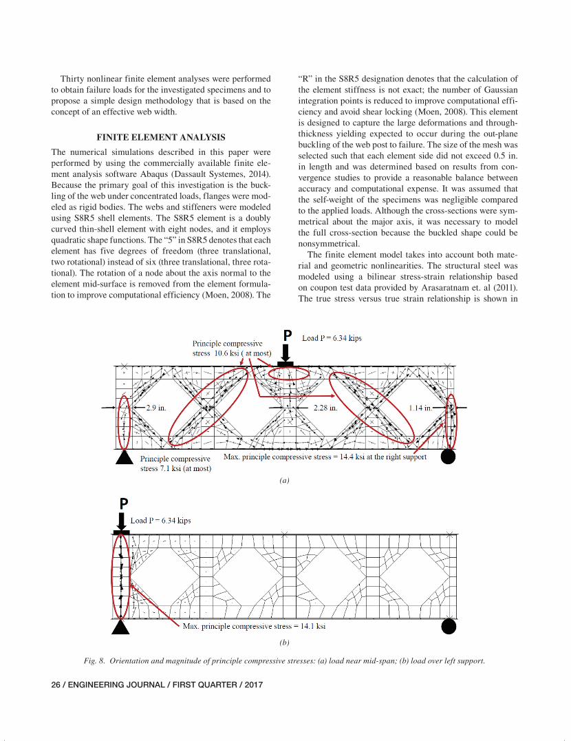
The concentrated loads were assumed to apply over the supports. This loading arrangement is believed to be the most critical for the limit state of web post buckling in com-pression, compared to other cases when the concentrated loads are applied away from the supports. To demonstrate this, a simply supported castellated beam was analyzed once with a concentrated load applied at mid-span and another time with a concentrated load applied over the left support. Figure 8 illustrates the orientation and magnitude of prin-cipal compressive stresses for both cases. When the load is
Table 1. Investigated Castellated Beams (CB)
W Section CB Section hwcb/tw
Section Length (S**) (in.) Aspect Ratio (S/dg**)
A,* B* C* A,* B* C*
W8×40 CB12×40 27.7 11.5 5.75 1 0.50
W12×50 CB18×50 44.7 15.0 7.50 0.83 0.42
W16×50 CB24×50 62.0 19.0 9.50 0.77 0.39
W21×62 CB30×62 76.7 23.0 11.5 0.76 0.38
W27×84 CB40×84 89.6 30.0 15.0 0.74 0.37
*Load position (Figure 7). **See Table 2.
021-044_EJQ117_2015-15R.indd 24 12/6/16 5:01 PM
ENGINEERING JOURNAL / FIRST QUARTER / 2017 / 25
applied at mid-span, the magnitude of the principal com-pressive stresses in the region underneath the load is 10.6 ksi at most. The orientation of the principal compressive stresses is vertical in the region immediately underneath the load and becomes more inclined and horizontal toward the bottom section of the beam. This is expected because the load is finding its way toward the supports. The maximum principal compressive stress occurs at the right support and is 14.4 ksi. When the load is applied over the left support, the
magnitude of the maximum compressive stress is 14.1 ksi, which is higher than the magnitude of principal compressive stresses underneath the load when the load was applied at mid-span, even though the width of web post at mid-height of the beam section is higher than the width at mid-span. This demonstrates that the most critical loading condition as it pertains to the limit state of web post buckling in compres-sion is when the load is applied directly over the support.
Table 2. Geometry of Investigated CBs
CB Section
e (in.)
b (in.)
dt (in.)
dg (in.)
tw (in.)
bf (in.)
tf (in.)
S (in.)
ho (in.)
h (in.)
Wo (in.)
Phi (deg)
CB12×40 4.0 1.75 2.50 11.5 0.375 8.125 0.563 11.5 6.50 3.25 7.50 61.70
CB18×50 4.5 3.25 3.25 18.0 0.375 8.125 0.625 15.0 11.375 5.75 10.75 60.27
CB24×50 4.5 5.00 4.00 24.5 0.375 7.125 0.625 19.0 16.50 8.25 14.50 58.81
CB30×62 6.0 5.50 6.00 30.0 0.375 8.250 0.625 23.0 18.00 9.00 17.00 58.54
CB40×84 7.0 8.00 6.50 40.5 0.438 10.00 0.625 30.0 27.375 13.75 23.00 59.74
Fig. 7. Investigated cases.
021-044_EJQ117_2015-15R.indd 25 12/6/16 5:01 PM
26 / ENGINEERING JOURNAL / FIRST QUARTER / 2017
Thirty nonlinear finite element analyses were performed to obtain failure loads for the investigated specimens and to propose a simple design methodology that is based on the concept of an effective web width.
FINITE ELEMENT ANALYSIS
The numerical simulations described in this paper were performed by using the commercially available finite ele-ment analysis software Abaqus (Dassault Systemes, 2014). Because the primary goal of this investigation is the buck-ling of the web under concentrated loads, flanges were mod-eled as rigid bodies. The webs and stiffeners were modeled using S8R5 shell elements. The S8R5 element is a doubly curved thin-shell element with eight nodes, and it employs quadratic shape functions. The “5” in S8R5 denotes that each element has five degrees of freedom (three translational, two rotational) instead of six (three translational, three rota-tional). The rotation of a node about the axis normal to the element mid-surface is removed from the element formula-tion to improve computational efficiency (Moen, 2008). The
“R” in the S8R5 designation denotes that the calculation of the element stiffness is not exact; the number of Gaussian integration points is reduced to improve computational effi-ciency and avoid shear locking (Moen, 2008). This element is designed to capture the large deformations and through-thickness yielding expected to occur during the out-plane buckling of the web post to failure. The size of the mesh was selected such that each element side did not exceed 0.5 in. in length and was determined based on results from con-vergence studies to provide a reasonable balance between accuracy and computational expense. It was assumed that the self-weight of the specimens was negligible compared to the applied loads. Although the cross-sections were sym-metrical about the major axis, it was necessary to model the full cross-section because the buckled shape could be nonsymmetrical.
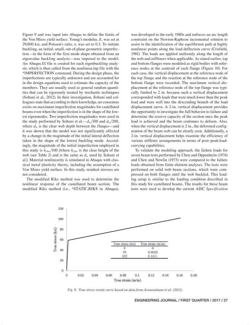
The finite element model takes into account both mate-rial and geometric nonlinearities. The structural steel was modeled using a bilinear stress-strain relationship based on coupon test data provided by Arasaratnam et. al (2011). The true stress versus true strain relationship is shown in
(a)
(b)
Fig. 8. Orientation and magnitude of principle compressive stresses: (a) load near mid-span; (b) load over left support.
021-044_EJQ117_2015-15R.indd 26 12/6/16 5:01 PM
ENGINEERING JOURNAL / FIRST QUARTER / 2017 / 27
Figure 9 and was input into Abaqus to define the limits of the Von Mises yield surface. Young’s modulus, E, was set at 29,000 ksi, and Poisson’s ratio, ν, was set to 0.3. To initiate buckling, an initial, small, out-of-plane geometric imperfec-tion—in the form of the first mode shape obtained from an eigenvalue buckling analysis—was imposed to the model. An Abaqus.fil file is created for each eigenbuckling analy-sis, which is then called from the nonlinear.inp file with the *IMPERFECTION command. During the design phase, the imperfections are typically unknown and are accounted for in the design equations used to estimate the capacity of the members. They are usually used as general random quanti-ties that can be rigorously treated by stochastic techniques (Soltani et al., 2012). In their investigation, Soltani and col-leagues state that according to their knowledge, no consensus exists on maximum imperfection magnitudes for castellated beams even when the imperfection is in the shape of the low-est eigenmodes. Two imperfection magnitudes were used in the study performed by Soltani et al.—dw/100 and dw/200, where dw is the clear web depth between the flanges—and it was shown that the model was not significantly affected by a change in the magnitude of the initial lateral deflection taken in the shape of the lowest buckling mode. Accord-ingly, the magnitude of the initial imperfection employed in this study is hcbw/100 [where hcbw is the clear height of the web (see Table 2) and is the same as dw used by Soltani et al.]. Material nonlinearity is simulated in Abaqus with clas-sical metal plasticity theory, including the assumption of a Von Mises yield surface. In this study, residual stresses are not considered.
The modified Riks method was used to determine the nonlinear response of the castellated beam section. The modified Riks method (i.e., *STATIC,RIKS in Abaqus),
was developed in the early 1980s and enforces an arc length constraint on the Newton-Raphson incremental solution to assist in the identification of the equilibrium path at highly nonlinear points along the load-deflection curve (Crisfield, 1981). The loads are applied uniformly along the length of the web and stiffeners when applicable. As stated earlier, top and bottom flanges were modeled as rigid bodies with refer-ence nodes at the centroid of each flange (Figure 10). For each case, the vertical displacement at the reference node of the top flange and the reaction at the reference node of the bottom flange were recorded. The maximum vertical dis-placement at the reference node of the top flange was typi-cally limited to 2 in. because such a vertical displacement corresponded with loads that were much lower than the peak load and were well into the descending branch of the load displacement curve. A 2-in. vertical displacement provides the opportunity to investigate the full behavior to failure and determine the reserve capacity of the section once the peak load is achieved and the beam continues to deform. Also, when the vertical displacement is 2 in., the deformed config-uration of the beam web can be clearly seen. Additionally, a 2-in. vertical displacement helps examine the efficiency of various stiffener arrangements in terms of post–peak-load-carrying capabilities.
To validate the modeling approach, the failure loads for seven beam tests performed by Chen and Oppenheim (1974) and Chen and Newlin (1973) were compared to the failure loads obtained from finite element analyses. The tests were performed on solid web beam sections, which were com-pressed on both flanges until the web buckled. This load-ing setup is similar to the loading condition described in this study for castellated beams. The results for these beam tests were used to develop the current AISC Specification
Fig. 9. True stress-strain curve based on data from Arasaratnam et al. (2011).
021-044_EJQ117_2015-15R.indd 27 12/6/16 5:01 PM
28 / ENGINEERING JOURNAL / FIRST QUARTER / 2017
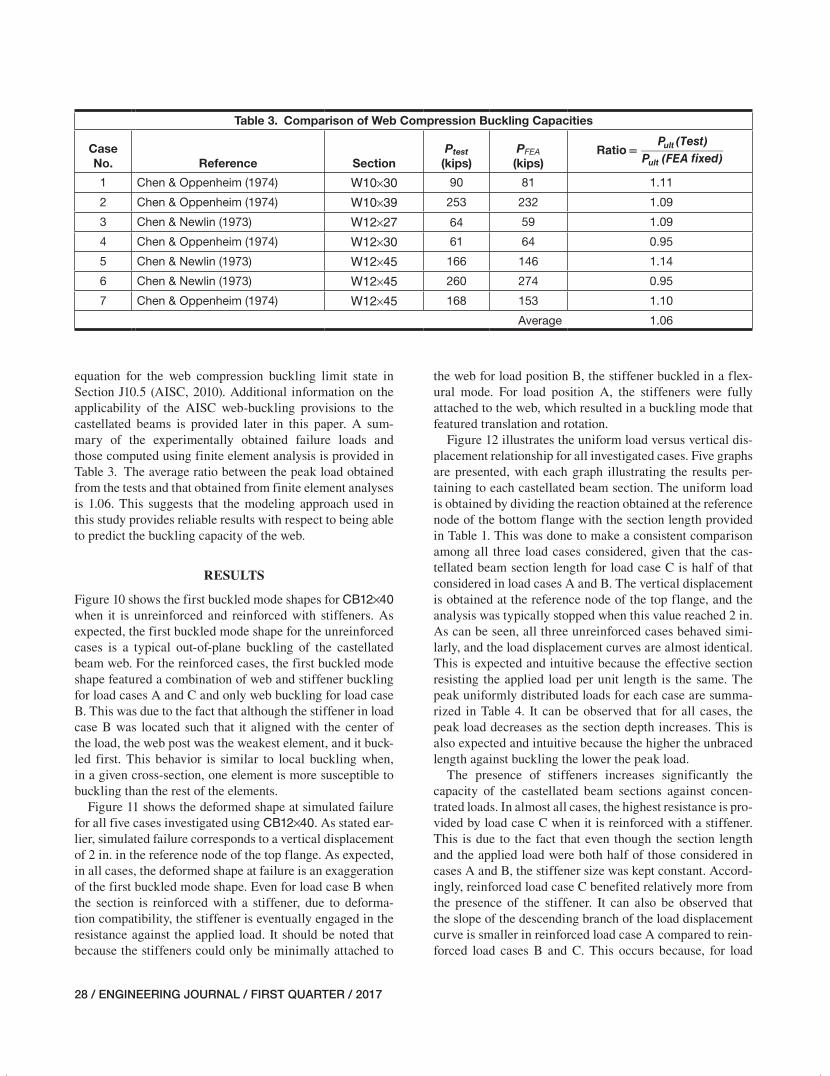
equation for the web compression buckling limit state in Section J10.5 (AISC, 2010). Additional information on the applicability of the AISC web-buckling provisions to the castellated beams is provided later in this paper. A sum-mary of the experimentally obtained failure loads and those computed using finite element analysis is provided in Table 3. The average ratio between the peak load obtained from the tests and that obtained from finite element analyses is 1.06. This suggests that the modeling approach used in this study provides reliable results with respect to being able to predict the buckling capacity of the web.
RESULTS
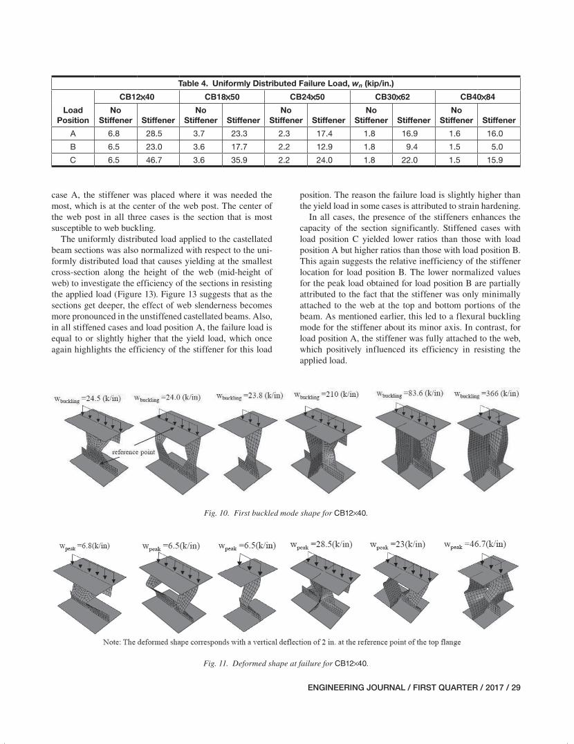
Figure 10 shows the first buckled mode shapes for CB12×40 when it is unreinforced and reinforced with stiffeners. As expected, the first buckled mode shape for the unreinforced cases is a typical out-of-plane buckling of the castellated beam web. For the reinforced cases, the first buckled mode shape featured a combination of web and stiffener buckling for load cases A and C and only web buckling for load case B. This was due to the fact that although the stiffener in load case B was located such that it aligned with the center of the load, the web post was the weakest element, and it buck-led first. This behavior is similar to local buckling when, in a given cross-section, one element is more susceptible to buckling than the rest of the elements.
Figure 11 shows the deformed shape at simulated failure for all five cases investigated using CB12×40. As stated ear-lier, simulated failure corresponds to a vertical displacement of 2 in. in the reference node of the top flange. As expected, in all cases, the deformed shape at failure is an exaggeration of the first buckled mode shape. Even for load case B when the section is reinforced with a stiffener, due to deforma-tion compatibility, the stiffener is eventually engaged in the resistance against the applied load. It should be noted that because the stiffeners could only be minimally attached to
the web for load position B, the stiffener buckled in a flex-ural mode. For load position A, the stiffeners were fully attached to the web, which resulted in a buckling mode that featured translation and rotation.
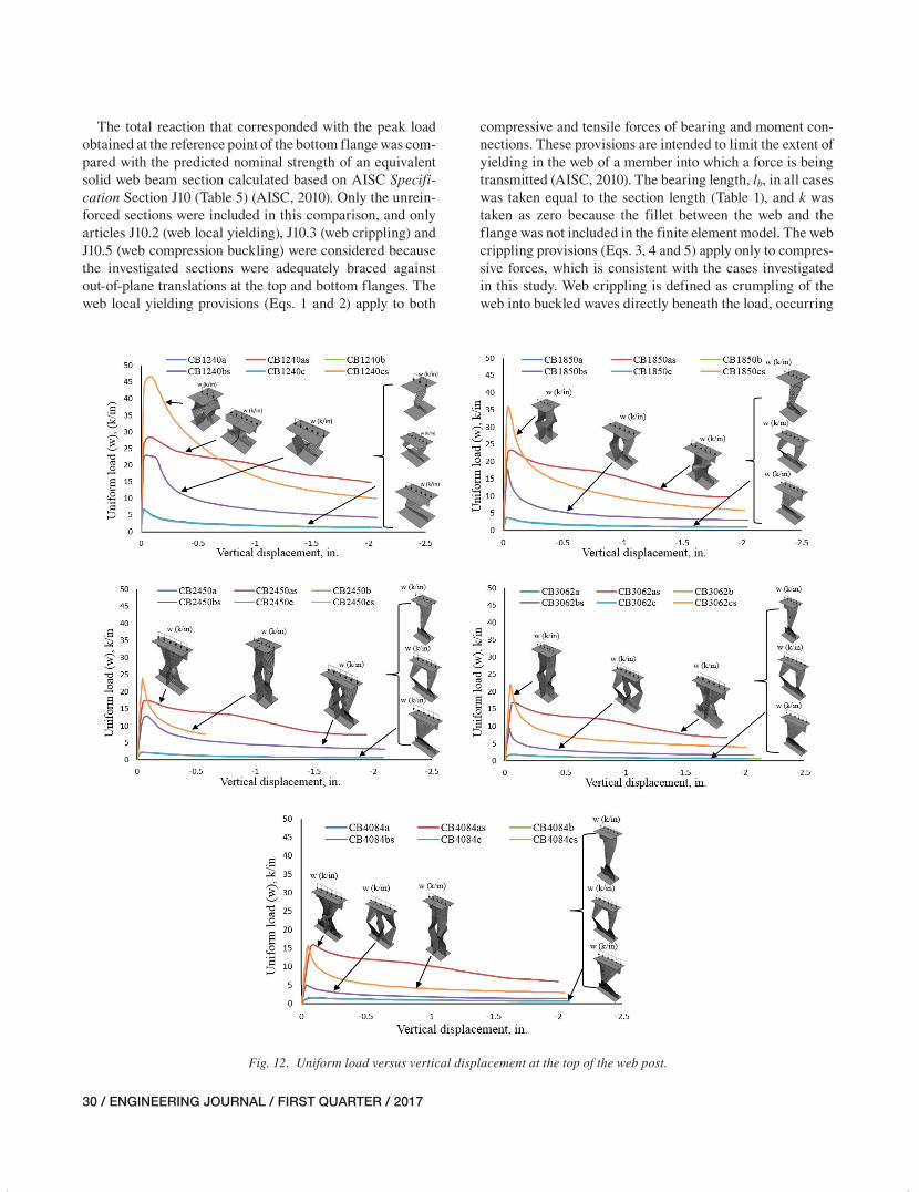
Figure 12 illustrates the uniform load versus vertical dis-placement relationship for all investigated cases. Five graphs are presented, with each graph illustrating the results per-taining to each castellated beam section. The uniform load is obtained by dividing the reaction obtained at the reference node of the bottom flange with the section length provided in Table 1. This was done to make a consistent comparison among all three load cases considered, given that the cas-tellated beam section length for load case C is half of that considered in load cases A and B. The vertical displacement is obtained at the reference node of the top flange, and the analysis was typically stopped when this value reached 2 in. As can be seen, all three unreinforced cases behaved simi-larly, and the load displacement curves are almost identical. This is expected and intuitive because the effective section resisting the applied load per unit length is the same. The peak uniformly distributed loads for each case are summa-rized in Table 4. It can be observed that for all cases, the peak load decreases as the section depth increases. This is also expected and intuitive because the higher the unbraced length against buckling the lower the peak load.
The presence of stiffeners increases significantly the capacity of the castellated beam sections against concen-trated loads. In almost all cases, the highest resistance is pro-vided by load case C when it is reinforced with a stiffener. This is due to the fact that even though the section length and the applied load were both half of those considered in cases A and B, the stiffener size was kept constant. Accord-ingly, reinforced load case C benefited relatively more from the presence of the stiffener. It can also be observed that the slope of the descending branch of the load displacement curve is smaller in reinforced load case A compared to rein-forced load cases B and C. This occurs because, for load
Table 3. Comparison of Web Compression Buckling Capacities
Case No. Reference Section
Ptest (kips)
PFEA (kips)
(Test)PRatio =
P (FEA fixed)ult
ult
1 Chen & Oppenheim (1974) W10×30 90 81 1.11
2 Chen & Oppenheim (1974) W10×39 253 232 1.09
3 Chen & Newlin (1973) W12×27 64 59 1.09
4 Chen & Oppenheim (1974) W12×30 61 64 0.95
5 Chen & Newlin (1973) W12×45 166 146 1.14
6 Chen & Newlin (1973) W12×45 260 274 0.95
7 Chen & Oppenheim (1974) W12×45 168 153 1.10
Average 1.06
021-044_EJQ117_2015-15R.indd 28 12/6/16 5:01 PM
ENGINEERING JOURNAL / FIRST QUARTER / 2017 / 29
case A, the stiffener was placed where it was needed the most, which is at the center of the web post. The center of the web post in all three cases is the section that is most susceptible to web buckling.
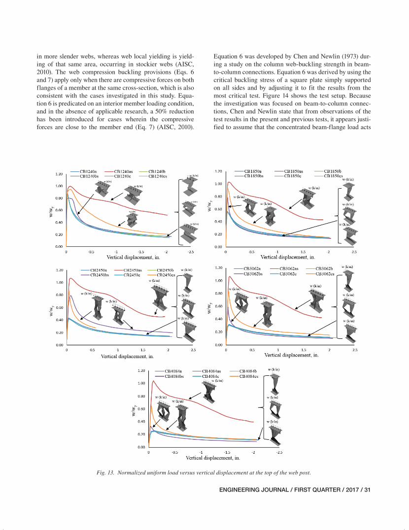
The uniformly distributed load applied to the castellated beam sections was also normalized with respect to the uni-formly distributed load that causes yielding at the smallest cross-section along the height of the web (mid-height of web) to investigate the efficiency of the sections in resisting the applied load (Figure 13). Figure 13 suggests that as the sections get deeper, the effect of web slenderness becomes more pronounced in the unstiffened castellated beams. Also, in all stiffened cases and load position A, the failure load is equal to or slightly higher that the yield load, which once again highlights the efficiency of the stiffener for this load
position. The reason the failure load is slightly higher than the yield load in some cases is attributed to strain hardening.
In all cases, the presence of the stiffeners enhances the capacity of the section significantly. Stiffened cases with load position C yielded lower ratios than those with load position A but higher ratios than those with load position B. This again suggests the relative inefficiency of the stiffener location for load position B. The lower normalized values for the peak load obtained for load position B are partially attributed to the fact that the stiffener was only minimally attached to the web at the top and bottom portions of the beam. As mentioned earlier, this led to a flexural buckling mode for the stiffener about its minor axis. In contrast, for load position A, the stiffener was fully attached to the web, which positively influenced its efficiency in resisting the applied load.
Fig. 10. First buckled mode shape for CB12×40.
Fig. 11. Deformed shape at failure for CB12×40.
Table 4. Uniformly Distributed Failure Load, wn (kip/in.)
Load Position
CB12×40 CB18×50 CB24×50 CB30×62 CB40×84
No Stiffener Stiffener
No Stiffener Stiffener
No Stiffener Stiffener
No Stiffener Stiffener
No Stiffener Stiffener
A 6.8 28.5 3.7 23.3 2.3 17.4 1.8 16.9 1.6 16.0
B 6.5 23.0 3.6 17.7 2.2 12.9 1.8 9.4 1.5 5.0
C 6.5 46.7 3.6 35.9 2.2 24.0 1.8 22.0 1.5 15.9
021-044_EJQ117_2015-15R.indd 29 12/6/16 5:01 PM
30 / ENGINEERING JOURNAL / FIRST QUARTER / 2017
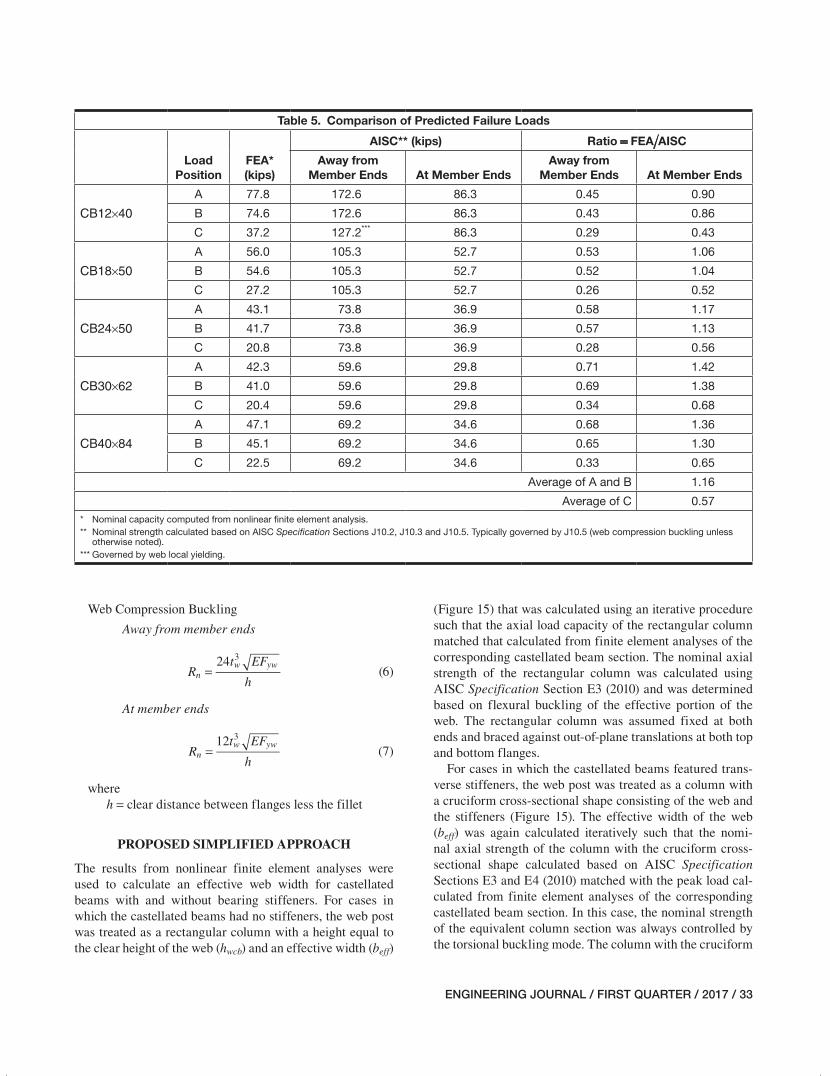
The total reaction that corresponded with the peak load obtained at the reference point of the bottom flange was com-pared with the predicted nominal strength of an equivalent solid web beam section calculated based on AISC Specifi-cation Section J10 (Table 5) (AISC, 2010). Only the unrein-forced sections were included in this comparison, and only articles J10.2 (web local yielding), J10.3 (web crippling) and J10.5 (web compression buckling) were considered because the investigated sections were adequately braced against out-of-plane translations at the top and bottom flanges. The web local yielding provisions (Eqs. 1 and 2) apply to both
compressive and tensile forces of bearing and moment con-nections. These provisions are intended to limit the extent of yielding in the web of a member into which a force is being transmitted (AISC, 2010). The bearing length, lb, in all cases was taken equal to the section length (Table 1), and k was taken as zero because the fillet between the web and the flange was not included in the finite element model. The web crippling provisions (Eqs. 3, 4 and 5) apply only to compres-sive forces, which is consistent with the cases investigated in this study. Web crippling is defined as crumpling of the web into buckled waves directly beneath the load, occurring
Fig. 12. Uniform load versus vertical displacement at the top of the web post.
021-044_EJQ117_2015-15R.indd 30 12/6/16 5:01 PM
ENGINEERING JOURNAL / FIRST QUARTER / 2017 / 31
in more slender webs, whereas web local yielding is yield-ing of that same area, occurring in stockier webs (AISC, 2010). The web compression buckling provisions (Eqs. 6 and 7) apply only when there are compressive forces on both flanges of a member at the same cross-section, which is also consistent with the cases investigated in this study. Equa-tion 6 is predicated on an interior member loading condition, and in the absence of applicable research, a 50% reduction has been introduced for cases wherein the compressive forces are close to the member end (Eq. 7) (AISC, 2010).
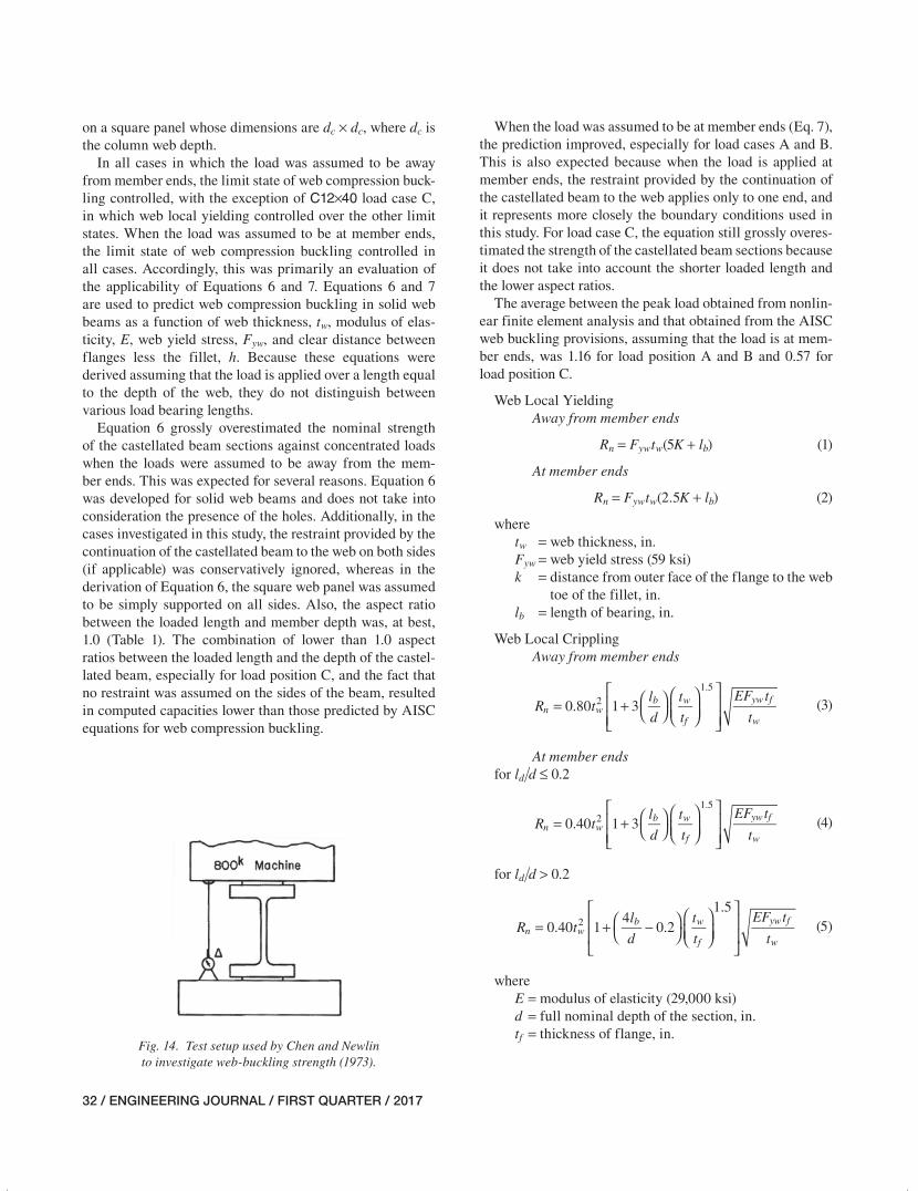
Equation 6 was developed by Chen and Newlin (1973) dur-ing a study on the column web-buckling strength in beam-to-column connections. Equation 6 was derived by using the critical buckling stress of a square plate simply supported on all sides and by adjusting it to fit the results from the most critical test. Figure 14 shows the test setup. Because the investigation was focused on beam-to-column connec-tions, Chen and Newlin state that from observations of the test results in the present and previous tests, it appears justi-fied to assume that the concentrated beam-flange load acts
Fig. 13. Normalized uniform load versus vertical displacement at the top of the web post.
021-044_EJQ117_2015-15R.indd 31 12/6/16 5:01 PM
32 / ENGINEERING JOURNAL / FIRST QUARTER / 2017
on a square panel whose dimensions are dc × dc, where dc is the column web depth.
In all cases in which the load was assumed to be away from member ends, the limit state of web compression buck-ling controlled, with the exception of C12×40 load case C, in which web local yielding controlled over the other limit states. When the load was assumed to be at member ends, the limit state of web compression buckling controlled in all cases. Accordingly, this was primarily an evaluation of the applicability of Equations 6 and 7. Equations 6 and 7 are used to predict web compression buckling in solid web beams as a function of web thickness, tw, modulus of elas-ticity, E, web yield stress, Fyw, and clear distance between flanges less the fillet, h. Because these equations were derived assuming that the load is applied over a length equal to the depth of the web, they do not distinguish between various load bearing lengths.
Equation 6 grossly overestimated the nominal strength of the castellated beam sections against concentrated loads when the loads were assumed to be away from the mem-ber ends. This was expected for several reasons. Equation 6 was developed for solid web beams and does not take into consideration the presence of the holes. Additionally, in the cases investigated in this study, the restraint provided by the continuation of the castellated beam to the web on both sides (if applicable) was conservatively ignored, whereas in the derivation of Equation 6, the square web panel was assumed to be simply supported on all sides. Also, the aspect ratio between the loaded length and member depth was, at best, 1.0 (Table 1). The combination of lower than 1.0 aspect ratios between the loaded length and the depth of the castel-lated beam, especially for load position C, and the fact that no restraint was assumed on the sides of the beam, resulted in computed capacities lower than those predicted by AISC equations for web compression buckling.
When the load was assumed to be at member ends (Eq. 7), the prediction improved, especially for load cases A and B. This is also expected because when the load is applied at member ends, the restraint provided by the continuation of the castellated beam to the web applies only to one end, and it represents more closely the boundary conditions used in this study. For load case C, the equation still grossly overes-timated the strength of the castellated beam sections because it does not take into account the shorter loaded length and the lower aspect ratios.
The average between the peak load obtained from nonlin-ear finite element analysis and that obtained from the AISC web buckling provisions, assuming that the load is at mem-ber ends, was 1.16 for load position A and B and 0.57 for load position C.
Web Local Yielding Away from member ends
Rn = Fywtw(5K + lb) (1)
At member ends
Rn = Fywtw(2.5K + lb) (2)
where tw = web thickness, in. Fyw = web yield stress (59 ksi) k = distance from outer face of the flange to the web
toe of the fillet, in. lb = length of bearing, in.
Web Local Crippling Away from member ends
= + ⎛⎝
⎞⎠⎛⎝⎜
⎞⎠⎟
⎡
⎣⎢⎢
⎤
⎦⎥⎥
R tl
d
t
t
EF t
t0.80 1 3n w
b w
f
yw f
w
21.5
(3)
At member endsfor ld/d ≤ 0.2
= + ⎛⎝
⎞⎠⎛⎝⎜
⎞⎠⎟
⎡
⎣⎢⎢
⎤
⎦⎥⎥
R tl
d
t
t
EF t
t0.40 1 3n w
b w
f
yw f
w
21.5
(4)
for ld/d > 0.2
= + −⎛⎝
⎞⎠⎛⎝⎜
⎞⎠⎟
⎡
⎣
⎢⎢
⎤
⎦
⎥⎥
R tl
d
t
t
EF t
t0.40 1
40.2
1.5
n wb w
f
yw f
w
2
(5)
where E = modulus of elasticity (29,000 ksi) d = full nominal depth of the section, in. tf = thickness of flange, in.
Fig. 14. Test setup used by Chen and Newlin to investigate web-buckling strength (1973).
021-044_EJQ117_2015-15R.indd 32 12/6/16 5:01 PM
ENGINEERING JOURNAL / FIRST QUARTER / 2017 / 33
Web Compression Buckling
Away from member ends
=R
t EF
h
24n
w yw3
(6)
At member ends
=R
t EF
h
12n
w yw3
(7)
where h = clear distance between flanges less the fillet
PROPOSED SIMPLIFIED APPROACH
The results from nonlinear finite element analyses were used to calculate an effective web width for castellated beams with and without bearing stiffeners. For cases in which the castellated beams had no stiffeners, the web post was treated as a rectangular column with a height equal to the clear height of the web (hwcb) and an effective width (beff)
Table 5. Comparison of Predicted Failure Loads
LoadPosition
FEA* (kips)
AISC** (kips) Ratio = FEA/AISC
Away from Member Ends At Member Ends
Away fromMember Ends At Member Ends
CB12×40
A 77.8 172.6 86.3 0.45 0.90
B 74.6 172.6 86.3 0.43 0.86
C 37.2 127.2*** 86.3 0.29 0.43
CB18×50
A 56.0 105.3 52.7 0.53 1.06
B 54.6 105.3 52.7 0.52 1.04
C 27.2 105.3 52.7 0.26 0.52
CB24×50
A 43.1 73.8 36.9 0.58 1.17
B 41.7 73.8 36.9 0.57 1.13
C 20.8 73.8 36.9 0.28 0.56
CB30×62
A 42.3 59.6 29.8 0.71 1.42
B 41.0 59.6 29.8 0.69 1.38
C 20.4 59.6 29.8 0.34 0.68
CB40×84
A 47.1 69.2 34.6 0.68 1.36
B 45.1 69.2 34.6 0.65 1.30
C 22.5 69.2 34.6 0.33 0.65
Average of A and B 1.16
Average of C 0.57* Nominal capacity computed from nonlinear finite element analysis.** Nominal strength calculated based on AISC Specification Sections J10.2, J10.3 and J10.5. Typically governed by J10.5 (web compression buckling unless
otherwise noted).*** Governed by web local yielding.
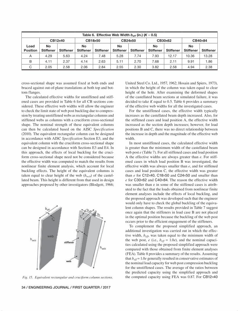
(Figure 15) that was calculated using an iterative procedure such that the axial load capacity of the rectangular column matched that calculated from finite element analyses of the corresponding castellated beam section. The nominal axial strength of the rectangular column was calculated using AISC Specification Section E3 (2010) and was determined based on flexural buckling of the effective portion of the web. The rectangular column was assumed fixed at both ends and braced against out-of-plane translations at both top and bottom flanges.
For cases in which the castellated beams featured trans-verse stiffeners, the web post was treated as a column with a cruciform cross-sectional shape consisting of the web and the stiffeners (Figure 15). The effective width of the web (beff) was again calculated iteratively such that the nomi-nal axial strength of the column with the cruciform cross-sectional shape calculated based on AISC Specification Sections E3 and E4 (2010) matched with the peak load cal-culated from finite element analyses of the corresponding castellated beam section. In this case, the nominal strength of the equivalent column section was always controlled by the torsional buckling mode. The column with the cruciform
021-044_EJQ117_2015-15R.indd 33 12/6/16 5:01 PM
34 / ENGINEERING JOURNAL / FIRST QUARTER / 2017
cross-sectional shape was assumed fixed at both ends and braced against out-of-plane translations at both top and bot-tom flanges.
The calculated effective widths for unstiffened and stiff-ened cases are provided in Table 6 for all CB sections con-sidered. These effective web widths will allow the engineer to check the limit state of web post buckling due to compres-sion by treating unstiffened webs as rectangular columns and stiffened webs as columns with a cruciform cross-sectional shape. The nominal strength of these equivalent columns can then be calculated based on the AISC Specification (2010). The equivalent rectangular column can be designed in accordance with AISC Specification Section E3, and the equivalent column with the cruciform cross-sectional shape can be designed in accordance with Sections E3 and E4. In this approach, the effects of local buckling for the cruci-form cross-sectional shape need not be considered because the effective width was computed to match the results from nonlinear finite element analysis, which account for local buckling effects. The height of the equivalent columns is taken equal to clear height of the web (hwcb) of the castel-lated beam. This height is different from that used in design approaches proposed by other investigators (Blodgett, 1966;
United Steel Co. Ltd., 1957, 1962; Hosain and Spiers, 1973), in which the height of the column was taken equal to clear height of the hole. After examining the deformed shapes of the castellated beam sections at simulated failure, it was decided to take K equal to 0.5. Table 6 provides a summary of the effective web widths for all the investigated cases.
For the unstiffened cases, the effective width typically increases as the castellated beam depth increased. Also, for the stiffened cases and load position A, the effective width increased as the section depth increases; however, for load positions B and C, there was no direct relationship between the increase in depth and the magnitude of the effective web width.
In most unstiffened cases, the calculated effective width is greater than the minimum width of the castellated beam web post e (Table 7). For all stiffened cases and load position A the effective widths are always greater than e. For stiff-ened cases in which load position B was investigated, the effective width was always smaller than e, and for stiffened cases and load position C, the effective width was greater than e for C12×40, C18×50 and C24×50 and smaller than e for C30×62 and C40×84. The reason the effective width was smaller than e in some of the stiffened cases is attrib-uted to the fact that the loads obtained from nonlinear finite element analyses include the effects of local buckling, and the proposed approach was developed such that the engineer would only have to check the global buckling of the equiva-lent column shapes. The results provided in Table 7 suggest once again that the stiffeners in load case B are not placed in the optimal position because the buckling of the web post occurs prior to the efficient engagement of the stiffeners.
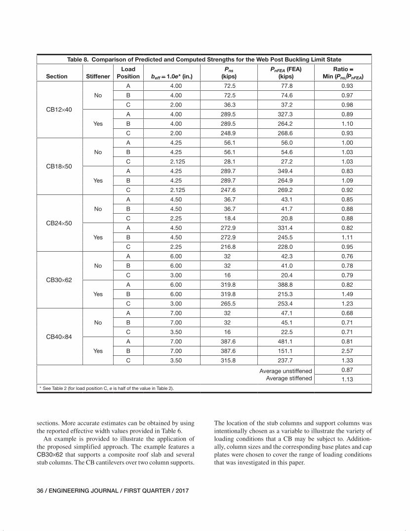
To complement the proposed simplified approach, an additional investigation was carried out in which the effec-tive width, beff, was taken equal to the minimum width of the web post, e (i.e., beff = 1.0e), and the nominal capaci-ties calculated using the proposed simplified approach were compared with those obtained from finite element analyses (FEA). Table 8 provides a summary of the results. Assuming that beff = 1.0e generally resulted in conservative estimates of the nominal load capacity for web post compression buckling for the unstiffened cases. The average of the ratios between the predicted capacity using the simplified approach and the computed capacity using FEA was 0.87. For CB12×40
Table 6. Effective Web Width beff (in.) (K = 0.5)
Load Position
CB12×40 CB18×50 CB24×50 CB30×62 CB40×84
No Stiffener Stiffener
No Stiffener Stiffener
No Stiffener Stiffener
No Stiffener Stiffener
No Stiffener Stiffener
A 4.29 5.63 4.24 7.48 5.28 7.74 7.93 12.17 10.36 13.28
B 4.11 2.37 4.14 2.63 5.11 2.70 7.68 2.11 9.91 1.86
C 2.05 2.58 2.06 2.84 2.55 2.30 3.82 2.58 4.94 2.38
Fig. 15. Equivalent rectangular and cruciform column sections.
021-044_EJQ117_2015-15R.indd 34 12/6/16 5:01 PM
ENGINEERING JOURNAL / FIRST QUARTER / 2017 / 35
and CB18×50, this assumption led to rather accurate results for the unstiffened cases. However, as the castellated beam depth increased, this assumption led to more conservative results for castellated beams with no stiffeners.
For castellated beams with stiffeners and load position A, assuming that beff = 1.0e resulted in conservative esti-mates. For stiffened cases and load position B, this assump-tion always led to estimates that were higher than those
Table 7. Comparison of Effective Web Width with Minimum Width of Web Post (K = 0.5)
Section StiffenerLoad
Position beff* (in.) e** (in.)Section Width
(S**) (in.) Ratio = beff/e
CB12×40
No
A 4.29 4.00 11.5 1.07
B 4.11 4.00 11.5 1.03
C 2.05 2.00 5.75 1.03
Yes
A 5.63 4.00 11.5 1.41
B 2.37 4.00 11.5 0.59
C 2.58 2.00 5.75 1.29
CB18×50
No
A 4.24 4.25 15 1.00
B 4.14 4.25 15 0.97
C 2.06 2.125 7.5 0.97
Yes
A 7.48 4.25 15 1.76
B 2.63 4.25 15 0.62
C 2.84 2.125 7.5 1.34
CB24×50
No
A 5.28 4.50 19 1.17
B 5.11 4.50 19 1.14
C 2.55 2.25 9.5 1.13
Yes
A 7.74 4.50 19 1.72
B 2.70 4.50 19 0.60
C 2.30 2.25 9.5 1.02
CB30×62
No
A 7.93 6.00 23 1.32
B 7.68 6.00 23 1.28
C 3.82 3.00 11.5 1.27
Yes
A 12.17 6.00 23 2.03
B 2.11 6.00 23 0.35
C 2.58 3.00 11.5 0.86
CB40×84
No
A 10.36 7.00 30 1.48
B 9.91 7.00 30 1.42
C 4.94 3.50 15 1.41
Yes
A 13.28 7.00 30 1.90
B 1.86 7.00 30 0.27
C 2.38 3.50 15 0.68
* See Figure 7.** See Table 2.
computed from FEA. For stiffened cases and load position C, the results varied. For the first three castellated beams, the assumption led to rather accurate estimates, and for the last two, it led to estimates that were higher than those com-puted from FEA. In general, assuming that beff = 1.0e serves as a good starting point to create a general idea for the capac-ity of the web post in compression, with the exception of the stiffened cases for load position B and the two deeper beam
021-044_EJQ117_2015-15R.indd 35 12/6/16 5:01 PM
36 / ENGINEERING JOURNAL / FIRST QUARTER / 2017
Table 8. Comparison of Predicted and Computed Strengths for the Web Post Buckling Limit State
Section StiffenerLoad
Position beff = 1.0e* (in.)Pns
(kips)PnFEA (FEA)
(kips)Ratio =
Min (Pns/PnFEA)
CB12×40
No
A 4.00 72.5 77.8 0.93
B 4.00 72.5 74.6 0.97
C 2.00 36.3 37.2 0.98
Yes
A 4.00 289.5 327.3 0.89
B 4.00 289.5 264.2 1.10
C 2.00 248.9 268.6 0.93
CB18×50
No
A 4.25 56.1 56.0 1.00
B 4.25 56.1 54.6 1.03
C 2.125 28.1 27.2 1.03
Yes
A 4.25 289.7 349.4 0.83
B 4.25 289.7 264.9 1.09
C 2.125 247.6 269.2 0.92
CB24×50
No
A 4.50 36.7 43.1 0.85
B 4.50 36.7 41.7 0.88
C 2.25 18.4 20.8 0.88
Yes
A 4.50 272.9 331.4 0.82
B 4.50 272.9 245.5 1.11
C 2.25 216.8 228.0 0.95
CB30×62
No
A 6.00 32 42.3 0.76
B 6.00 32 41.0 0.78
C 3.00 16 20.4 0.79
Yes
A 6.00 319.8 388.8 0.82
B 6.00 319.8 215.3 1.49
C 3.00 265.5 253.4 1.23
CB40×84
No
A 7.00 32 47.1 0.68
B 7.00 32 45.1 0.71
C 3.50 16 22.5 0.71
Yes
A 7.00 387.6 481.1 0.81
B 7.00 387.6 151.1 2.57
C 3.50 315.8 237.7 1.33
Average unstiffenedAverage stiffened
0.87
1.13* See Table 2 (for load position C, e is half of the value in Table 2).
sections. More accurate estimates can be obtained by using the reported effective width values provided in Table 6.
An example is provided to illustrate the application of the proposed simplified approach. The example features a CB30×62 that supports a composite roof slab and several stub columns. The CB cantilevers over two column supports.
The location of the stub columns and support columns was intentionally chosen as a variable to illustrate the variety of loading conditions that a CB may be subject to. Addition-ally, column sizes and the corresponding base plates and cap plates were chosen to cover the range of loading conditions that was investigated in this paper.
021-044_EJQ117_2015-15R.indd 36 12/6/16 5:01 PM
ENGINEERING JOURNAL / FIRST QUARTER / 2017 / 37
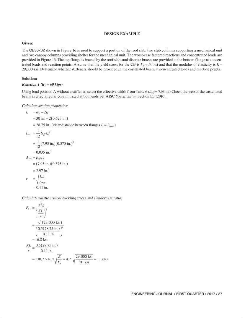
DESIGN EXAMPLE
Given:
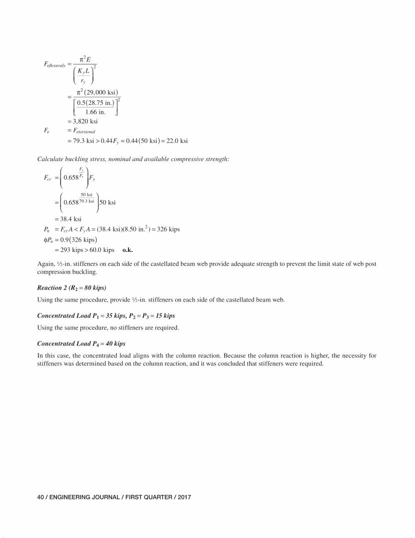
The CB30×62 shown in Figure 16 is used to support a portion of the roof slab, two stub columns supporting a mechanical unit and two canopy columns providing shelter for the mechanical unit. The worst-case factored reactions and concentrated loads are provided in Figure 16. The top flange is braced by the roof slab, and discrete braces are provided at the bottom flange at concen-trated loads and reaction points. Assume that the yield stress for the CB is Fy = 50 ksi and that the modulus of elasticity is E = 29,000 ksi. Determine whether stiffeners should be provided in the castellated beam at concentrated loads and reaction points.
Solution:
Reaction 1 (R1 = 60 kips)
Using load position A without a stiffener, select the effective width from Table 6 (beff = 7.93 in.) Check the web of the castellated beam as a rectangular column fixed at both ends per AISC Specification Section E3 (2010).
Calculate section properties:
( )( )
= −= −
= =
L d t
L h
2
30 in. 2 0.625 in.
28.75 in. clear distance between �anges
g f
wcb
( )( )
=
=
=
I b t1
121
127.93 in. 0.375 in.
0.035 in.
rec eff w3
3
4
( )( )==
=
A b t
7.93 in. 0.375 in.
2.97 in.
rec eff w
2
=
=
rI
A
0.11 in.
rec
rec
Calculate elastic critical buckling stress and slenderness ratio:
( )( )
=π
⎛⎝
⎞⎠
=π
⎛⎝⎜
⎞⎠⎟
=
FE
KL
r
29,000 ksi
0.5 28.75 in.0.11 in.
16.8 ksi
e
2
2
2
2
( )=
= > = =
KL
r
E
F
0.5 28.75 in.
0.11 in.
130.7 4.71 4.7129,000 ksi
50 ksi113.43
y
021-044_EJQ117_2015-15R.indd 37 12/6/16 5:01 PM
38 / ENGINEERING JOURNAL / FIRST QUARTER / 2017
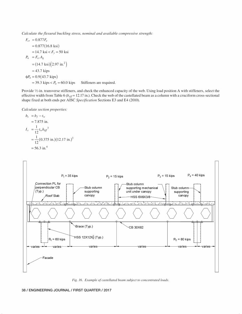
Calculate the flexural buckling stress, nominal and available compressive strength:
( )=== < =
F F
F
0.877
0.877 16.8 ksi
14.7 ksi 50 ksi
cr e
y
( )( )=
=
=
P F A
14.7 ksi 2.97 in.
43.7 kips
n cr g
2
( )ϕ == < =
P
P
0.9 43.7 kips
39.3 kips 60.0 kips Stiffeners are required.n
u
Provide 2-in. transverse stiffeners, and check the enhanced capacity of the web. Using load position A with stiffeners, select the effective width from Table 6 (beff = 12.17 in.). Check the web of the castellated beam as a column with a cruciform cross-sectional shape fixed at both ends per AISC Specification Sections E3 and E4 (2010).
Calculate section properties:
= −=
b b t
7.875 in.s f w
( )( )
=
=
=
I t b1
121
120.375 in. 12.17 in.
56.3 in.
x w eff3
3
4
Fig. 16. Example of castellated beam subject to concentrated loads.
021-044_EJQ117_2015-15R.indd 38 12/6/16 5:01 PM
ENGINEERING JOURNAL / FIRST QUARTER / 2017 / 39
( )( ) ( )( )
= ⎛⎝
⎞⎠ + ⎛
⎝⎞⎠ +⎛⎝
⎞⎠
⎡
⎣⎢
⎤
⎦⎥
= + +⎛⎝
⎞⎠
⎡
⎣⎢
⎤
⎦⎥
=
I tb
tb b t
21
12 2 2 4 2
21
120.5 in. 3.9375 in. 0.5 in. 3.9375 in.
3.9375 in.
2
0.375 in.
2
23.39 in.
y ss
ss s w
3 2
32
4
( )( ) ( )( )= += +
=
A b t b t
12.17 in. 0.375 in. 7.875 in. 0.5 in.
8.50 in.
eff w s s
2
( )( ) ( )( )
= +
= +
=
J b t b t1
3
1
31
37.875 in. 0.5 in.
1
312.17 in. 0.375 in.
0.542 in.
s s eff w3 3
3 3
4
( )( ) ( )( )
= +
= +
=
C b t b t1
9
1
91
97.875 in. 0.5 in.
1
912.17 in. 0.375 in.
0.181 in.
w s s eff w3 3
3 3
4
=
=
=
rI
A
56.3 in.
8.50 in.2.57 in.
xx
4
2
=
=
=
rI
A
23.39 in.
8.50 in.1.66 in.
yy
4
2
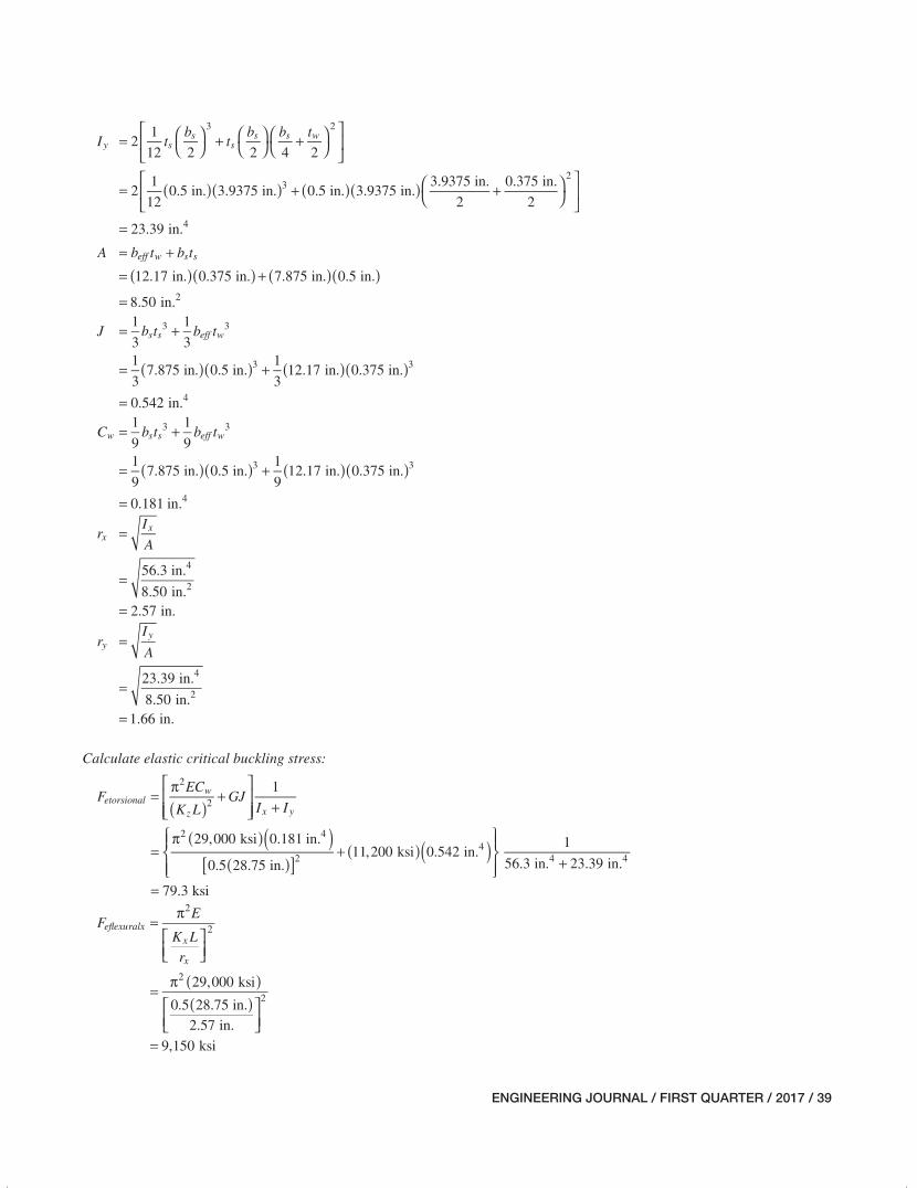
Calculate elastic critical buckling stress:
( ) ( )[ ]
( )( )
( )( )
=π
+⎡
⎣⎢⎢
⎤
⎦⎥⎥ +
=π
+⎧⎨⎪
⎩⎪
⎫⎬⎪
⎭⎪ +
=
FEC
K LGJ
I I
1
29,000 ksi 0.181 in.
0.5 28.75 in.11,200 ksi 0.542 in.
1
56.3 in. 23.39 in.
79.3 ksi
etorsionalw
z x y
2
2
2 4
24
4 4
( )( )
=π
⎡⎣⎢
⎤⎦⎥
=π
⎡⎣⎢
⎤⎦⎥
=
FE
K L
r
29,000 ksi
0.5 28.75 in.2.57 in.
9,150 ksi
e�exuralxx
x
2
2
2
2
021-044_EJQ117_2015-15R.indd 39 12/6/16 5:01 PM
40 / ENGINEERING JOURNAL / FIRST QUARTER / 2017
( )( )
=π
⎛⎝⎜
⎞⎠⎟
=π
⎡⎣⎢
⎤⎦⎥
=
FE
K L
r
29,000 ksi
0.5 28.75 in.1.66 in.
3,820 ksi
e�exuraly
y
y
2
2
2
2
( )== > = =
F F
F79.3 ksi 0.44 0.44 50 ksi 22.0 ksi
e etorsional
y
Calculate buckling stress, nominal and available compressive strength:
=⎛
⎝⎜⎜
⎞
⎠⎟⎟
=⎛
⎝⎜
⎞
⎠⎟
=
FF 0.658
0.658 50 ksi
38.4 ksi
cr
F
Fy
50 ksi
79.3 ksi
y
e
= < = =P F A F A (38.4 ksi)(8.50 in. ) 326 kipsn cr y2
o.k.
( )φ == >
P 0.9 326 kips
293 kips 60.0 kipsn
Again, 2-in. stiffeners on each side of the castellated beam web provide adequate strength to prevent the limit state of web post compression buckling.
Reaction 2 (R2 = 80 kips)
Using the same procedure, provide 2-in. stiffeners on each side of the castellated beam web.
Concentrated Load P1 = 35 kips, P2 = P3 = 15 kips
Using the same procedure, no stiffeners are required.
Concentrated Load P4 = 40 kips
In this case, the concentrated load aligns with the column reaction. Because the column reaction is higher, the necessity for stiffeners was determined based on the column reaction, and it was concluded that stiffeners were required.
021-044_EJQ117_2015-15R.indd 40 12/6/16 5:01 PM
ENGINEERING JOURNAL / FIRST QUARTER / 2017 / 41
CONCLUSIONS
The research presented in this paper addressed the need for a design method to estimate the nominal capacity of cas-tellated beams against concentrated loads as it pertains to the limit state of web post buckling in compression. The other limit states summarized in the Introduction—such as flexural failure, shear failure, lateral torsional buckling, Vierendeel mechanism, local buckling, buckling of the web post due to shear and fracture of a welded joint—should each be checked as described in the provided References so that the overall safety of the castellated beam in question is ensured. This investigation dealt with a loading condition in which the load is applied over a support. This was done to specifically study the limit state of web post buckling in compression. It was demonstrated that this loading condi-tion represents the worst-case scenario with respect to the limit state of web post buckling in compression and that other conditions in which the load is away from the supports can be conservatively checked using the simplified approach presented herein.
Five castellated beam section depths were considered, which cover a wide range of the available depths. For each section three load cases were considered: (A) center of load aligns with the middle of web post, (B) center of load aligns with the center of the hole, and (C) center of load aligns with a point halfway between the center of web post and center of hole. For each load position, two cases were considered: one without a stiffener and one with a full-height stiffener. This resulted in a total of 30 cases, which were investigated using nonlinear finite element analyses that accounted for geometric and material nonlinearities, including the effect of initial imperfections.
The peak loads obtained from the analyses of unstiffened cases were compared with AISC Specification (2010) provi-sions for flanges and solid webs with concentrated forces. Only Sections J10.2, J10.3 and J10.5 were considered for comparison because the castellated beam sections were assumed to be adequately braced for out-of-plane trans-lations at the top and bottom flanges. When the load was considered to be away from member ends, AISC provisions for solid web beams grossly overestimated the capacity of the sections under consideration. This was expected for sev-eral reasons. Equation 6 was developed for solid web beams and does not take into consideration the presence of the holes. Additionally, in the cases investigated in this study, the restraint provided by the continuation of the castellated beam to the web on both sides (if applicable) was conserva-tively ignored, whereas in the derivation of Equation 6, the square web panel was assumed to be simply supported on all sides. Also, the aspect ratio between the loaded length and member depth was, at best, 1.0 (Table 1). When the load was assumed to be at member ends (Eq. 7), the predic-tion improved, especially for load cases A and B. This is
also expected because, when the load is applied at member ends, the restraint provided by the continuation of the beam to the web applies only to one end, and it represents more closely the boundary conditions used in this study. For load case C, the equation still grossly overestimated the capac-ity of the castellated beam sections because it does not take into account the shorter loaded length and the lower aspect ratios. The average between the peak load obtained from nonlinear finite element analysis and that obtained from the AISC Specification web buckling provisions, assuming that the load is at member ends, was 1.16 for load position A and B and 0.57 for load position C. It was pointed out that the current equations in the AISC Specification in Section J10.5 for checking the limit state of web compression buckling in wide flange beams do not distinguish between various load-bearing lengths. This shortcoming is currently being addressed as part of another study.
A simplified approach was presented for checking the limit state of web post buckling in compression, which con-siders the web of a castellated beam as an equivalent col-umn whose height is equal to the clear height of the web. This simplified approach assumes that the top and bottom flanges are adequately braced against out-of-plane transla-tions. For the unstiffened cases, the equivalent column has a rectangular cross-section whose thickness is equal to the thickness of the web, and the width can be determined based on the effective width values presented in this paper. This equivalent rectangular column can be checked using AISC Specification provisions in Section E3 (AISC, 2010). For the stiffened case, the equivalent column has a cruciform cross-sectional shape that consists of the beam web and the stiffener. The width of the castellated beam web that can be used to determine the capacity of the column can be determined based on the effective width values presented in this paper. The equivalent column with a cruciform cross-sectional shape need only be checked for global buckling using the provisions of AISC Specification in Sections E3 and E4 because the effects of local buckling were included in the calculation of the effective web width. A K value equal to 0.5 is recommended based on an examination of the deformed shapes of castellated beam sections at simulated failure. It was demonstrated that taking beff = 1.0e provided a rather accurate estimate of the load capacities for CB12×40 and CB18×50, and a conservative estimate for the rest of the castellated beams examined. It was also demonstrated that beff = 1.0e taking for all stiffened cases and load position A resulted in conservative estimates for the web post buckling capacity. The estimated capacity for stiffened cases and load position B based on this assumption was always higher than that computed from FEA. The results for stiffened cases and load position C varied.
The capacity of the unstiffened beams against concen-trated loads, as it relates to the limit state of buckling of the
021-044_EJQ117_2015-15R.indd 41 12/6/16 5:01 PM
42 / ENGINEERING JOURNAL / FIRST QUARTER / 2017
web post in compression, ranged from 1.5 kip/in. to 6.8 kip/in., assuming that the load was applied over a distance equal to the spacing of the holes for load cases A and B and half the distance between the holes for load case C. These capac-ities were significantly increased when the castellated beam sections were reinforced with stiffeners, and they ranged from 5 kip/in. to 47 kip/in.
The results presented in this paper can be used to deter-mine the requirement for stiffeners in castellated beams to prevent the buckling of the web post due to compression. Physical testing of castellated beam sections subject to com-pression loads similar to the tests performed by Chen and Oppenheim (1974) and Chen and Newlin (1973) should be conducted to complement the results obtained from the ana-lytical work presented in this study.
Recommendations for Other Cases
The results presented in this paper can be directly applied in cases where the castellated beam sizes match those investigated herein. For other cases, the following practi-cal approaches are recommended unless a finite element study is undertaken. For unstiffened castellated beams that are properly braced against out-of-plane translations at the top and bottom flanges, the effective web width, beff, for all loading cases considered can be taken equal to e (minimum width of the web post) because, in all investigated cases, the calculated effective width was typically larger than e. In the CB18×50 case, for load positions B and C, the ratio beff/e was slightly smaller than one (0.97); however, such a small difference is inconsequential given the level of accuracy considered in structural design. Additionally, it was demon-strated that taking beff = 1.0e provided a rather accurate esti-mate of the load capacities for the CB12×40 and CB18×50 and a conservative estimate for the rest of the castellated beams examined. As discussed in the previous sections, the height of the equivalent rectangular column can be taken equal to hwcb, and K can be taken equal to 0.5. Additionally, if a more accurate estimate is desired, interpolation between the reported effective widths may be used for castellated beams that fall between CB24×50 and CB40×84 for the unstiffened cases.
For stiffened cases and load position A, Figure 13 sug-gests that the capacity for the limit state of web compression buckling can be based on the yield strength of the section at mid-height of the web. Additionally, it was demonstrated that taking beff = 1.0e for all stiffened cases and load posi-tion A resulted in conservative estimates for the web post buckling capacity.
For stiffened cases and load positions B and C, a ratio-nal comparison between the case in question and the cases investigated in this paper can be used to arrive at a reason-able conclusion.
REFERENCES
AISC (2010), Specification for Structural Steel Buildings, ANSI/AISC 360-10, American Institute of Steel Con-struction, Chicago, IL.
Arasaratnam, P., Sivakumaran, K.S. and Tait, M.J. (2011), “True Stress-True Strain Models for Structural Steel Ele-ments,” ISRN Civil Engineering, Vol. 2011, Article ID 656401, 11 pages, 2011. doi:10.5402/2011/656401.
Blodgett, O.W. (1966), Design of Welded Structures, The James F. Lincoln Arc Welding Foundation, Cleveland, OH.
Chen, W.F. and Newlin, D.E. (1973), “Column Web Strength in Steel Beam-to-Column Connections,” Journal of the Structural Division, ASCE, Vol. 99, ST9, September.
Chen, W.F. and Oppenheim, I.J. (1974), “Web Buckling Strength of Beam-to-Column Connections,” Journal of the Structural Division, ASCE, Vol. 100, ST1, January.
Crisfield, M.A. (1981), “A Fast Incremental/Iteration Solu-tion Procedure That Handles Snapthrough,” Computers and Structures, Vol. 13, pp. 55–62.
Darwin, D. (2003), Design Guide 2: Design of Steel and Composite Beams with Web Openings, American Insti-tute of Steel Construction, Chicago, IL.
Dassault Systemes Simulia Corp. (2014), Abaqus User’s Manual, Version 6.14-2.
Durif, S., Bouchaïr, A. and Vassart, O. (2013), “Experimen-tal Tests and Numerical Modeling of Cellular Beams with Sinusoidal Openings,” Journal of Constructional Steel Research, Vol. 82, pp. 72–87.
Ellobody, E. (2011), “Interaction of Buckling Modes in Cas-tellated Steel Beams,” Journal of Constructional Steel Research, Vol. 67, No. 5, pp. 814–825.
Ellobody, E. (2012), “Nonlinear Analysis of Cellular Steel Beams Under Combined Buckling Modes,” Thin-Walled Structures, Vol. 52, pp. 66–79.
ENV 1993-1-1 (1993), Eurocode 3: Design of Steel Struc-tures—Part 1–1: General Rules and Rules for Buildings, and Amendment A2 of Eurocode 3: Annex N Openings in Webs, British Standards Institution.
Halleux, P. (1967), “Limit Analysis of Castellated Steel Beams,” Acier-Stahl-Steel, Vol. 32, No. 3, pp. 133–144, March.
Hosain, M.U. and Spiers, W.G. (1973), “Experiments on Cas-tellated Steel Beams,” Supplement to Welding Journal, American Welding Society and the Welding Research Council.
Kerdal, D. and Nethercot, D.A. (1984), “Failure Modes for Castellated Beams,” Journal of Constructional Steel Research, Vol. 4, No. 4, pp. 295–315.
021-044_EJQ117_2015-15R.indd 42 12/6/16 5:01 PM
ENGINEERING JOURNAL / FIRST QUARTER / 2017 / 43
Moen, D.C. (2008), Direct Strength Design of Cold-Formed Steel Members with Perforations, Ph.D. Dissertation, John Hopkins University, Baltimore, MD.
Scherer Steel Structures, Inc. (2015), http://scherersteel.com/joists-girders/image001/.
Soltani, M.R., Bouchaïr, A. and Mimoune, M. (2012), “Non-linear FE Analysis of the Ultimate Behavior of Steel Castellated Beams,” Journal of Constructional Steel Research, Vol. 70, pp. 101–114.
SCI (2006), Design of Composite Beams with Large Open-ings for Services, Publication document RT959, version 05, May, Imperial College London, Silwood Park Cam-pus, Buckhurst Road, Ascot, West Berkshire, United Kingdom.
Tsavdaridis, K.D. and D’Mello, C. (2011), “Web Buckling Study of the Behavior and Strength of Perforated Steel Beams with Different Novel Web Opening Shapes,” Jour-nal of Constructional Steel Research, Vol. 67, No. 10, pp. 1605–1620.
Tsavdaridis, K. D., D’Mello, C. (2012), “Optimisation of Novel Elliptically-Based Web Opening Shapes of Per-forated Steel Beams,” Journal of Constructional Steel Research, vol. 76, pp. 39-53.
United Steel Co. Ltd., Research and Development Depart-ment (1957), Properties and Strengths of Castella Beams: Consideration of Previous Tests, Report D.GE. 71/262, Swinden Laboratories, Rotherham, April.
United Steel Co. Ltd., Research and Development Depart-ment (1962), Web Strength of Castella Beams, Report D.TS. 6/262/6, Swinden Laboratories, Rotherham, May.
Wang, P., Ma, Q. and Wang, X. (2014), “Investigation on Vierendeel Mechanism Failure of Castellated Steel Beams with Fillet Corner Web Openings,” Engineering Structures, Vol. 74, pp. 44–51.
Zaarour, W. and Redwood, R. (1996), “Web Buckling in Thin Webbed Castellated Beams,” Journal of Structural Engineering, ASCE, Vol. 122, No. 8, pp. 860–866.
021-044_EJQ117_2015-15R.indd 43 12/6/16 5:01 PM