Embed Size (px)
Citation preview

Investigation of the March 15, 2008 Fatal Tower Crane Collapse at 303 East 51st Street, New York, NY U.S. Department of Labor Occupational Safety and Health Administration Directorate of Construction September 2008
1
REPORT
Investigation of the March 15, 2008 Fatal Tower Crane Collapse at
303 East 51st Street, New York, NY
Report Prepared by Mohammad Ayub, PE Directorate of Construction, OSHA Washington, DC

2
Contributions to this report made by Dinesh Shah, PE, Directorate of Construction, OSHA National Office Manhattan OSHA Area Office, New York, NY
3
REPORT
The incident:
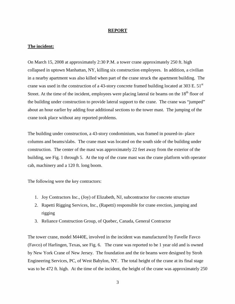
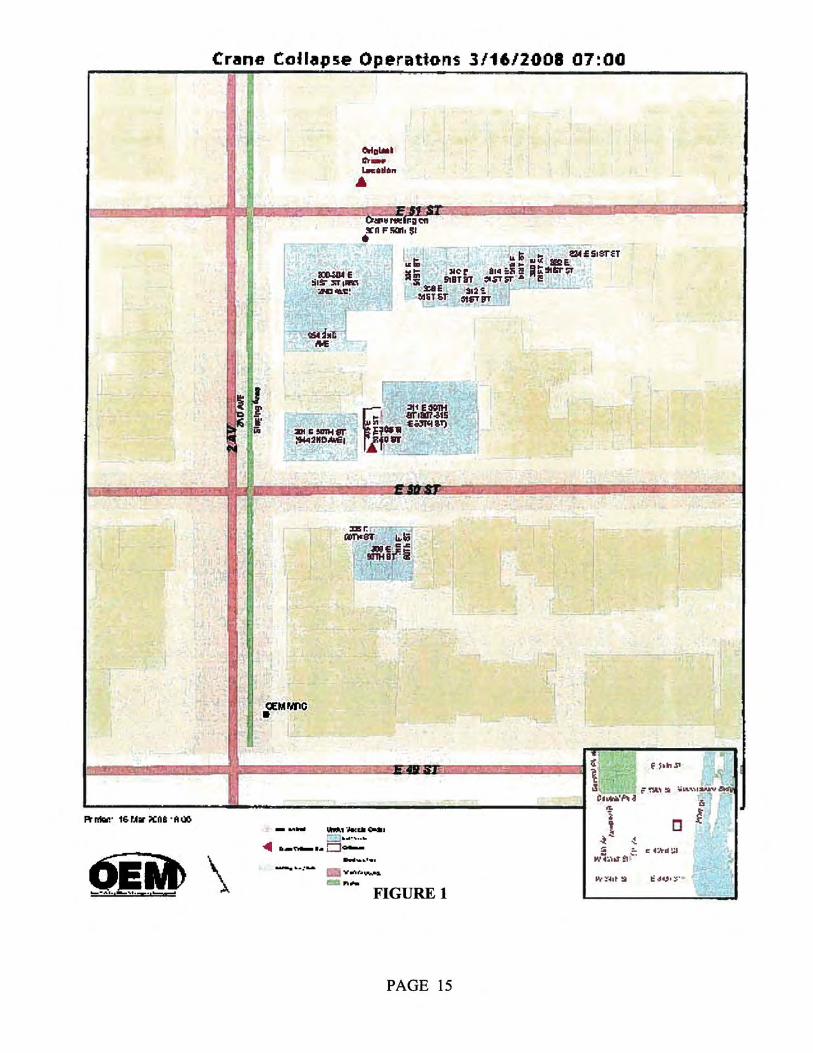
On March 15, 2008 at approximately 2:30 P.M. a tower crane approximately 250 ft. high
collapsed in uptown Manhattan, NY, killing six construction employees. In addition, a civilian
in a nearby apartment was also killed when part of the crane struck the apartment building. The
crane was used in the construction of a 43-story concrete framed building located at 303 E. 51st
Street. At the time of the incident, employees were placing lateral tie beams on the 18th floor of
the building under construction to provide lateral support to the crane. The crane was “jumped”
about an hour earlier by adding four additional sections to the tower mast. The jumping of the
crane took place without any reported problems.
The building under construction, a 43-story condominium, was framed in poured-in- place
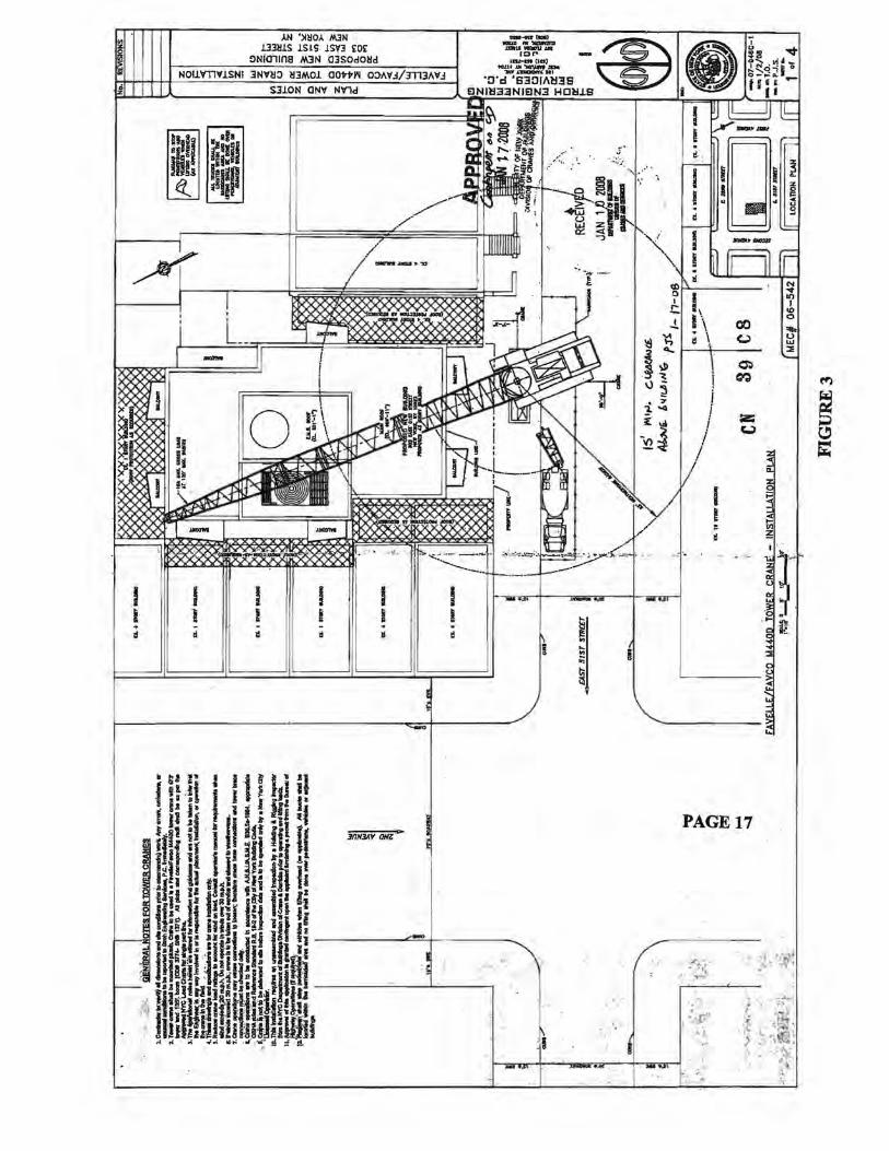
columns and beams/slabs. The crane mast was located on the south side of the building under
construction. The center of the mast was approximately 22 feet away from the exterior of the
building, see Fig. 1 through 5. At the top of the crane mast was the crane platform with operator
cab, machinery and a 120 ft. long boom.
The following were the key contractors:
1. Joy Contractors Inc., (Joy) of Elizabeth, NJ, subcontractor for concrete structure
2. Rapetti Rigging Services, Inc., (Rapetti) responsible for crane erection, jumping and
rigging
3. Reliance Construction Group, of Quebec, Canada, General Contractor
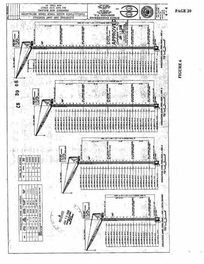
The tower crane, model M440E, involved in the incident was manufactured by Favelle Favco
(Favco) of Harlingen, Texas, see Fig. 6. The crane was reported to be 1 year old and is owned
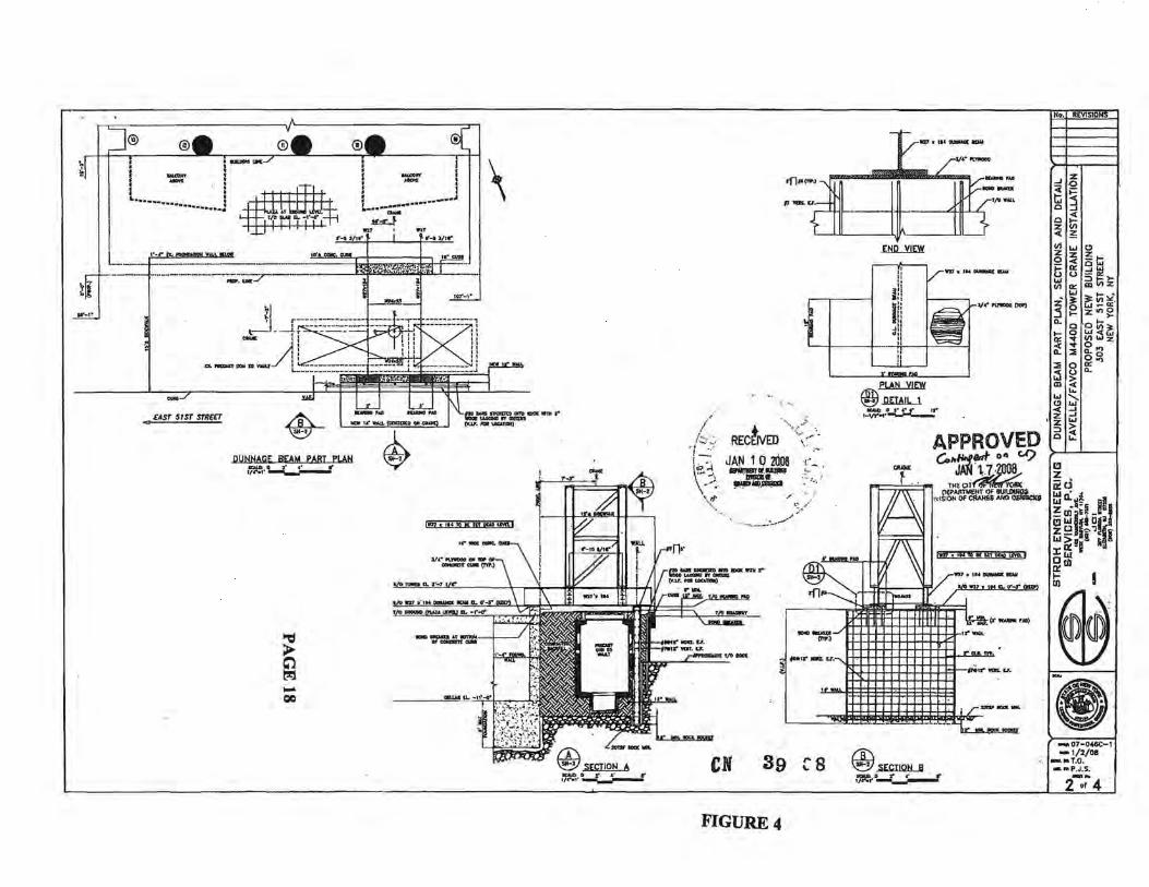
by New York Crane of New Jersey. The foundation and the tie beams were designed by Stroh
Engineering Services, PC, of West Babylon, NY. The total height of the crane at its final stage
was to be 472 ft. high. At the time of the incident, the height of the crane was approximately 250
4
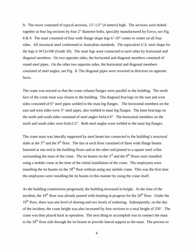
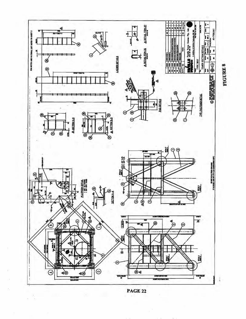
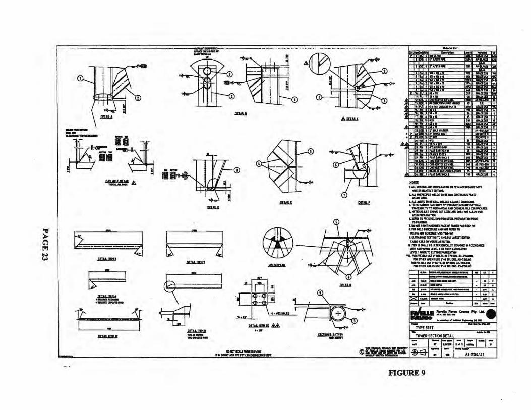
ft. The tower consisted of typical sections, 13’-1/2” (4 meters) high. The sections were bolted
together at four leg sections by four 2” diameter bolts, specially manufactured by Favco, see Fig.
8 & 9. The mast consisted of four wide flange shape legs 6’-10” center to center on all four
sides. All structural steel conformed to Australian standards. The equivalent U.S. steel shape for
the legs is W12x106 (Grade 50). The mast legs were connected to each other by horizontal and
diagonal members. On two opposite sides, the horizontal and diagonal members consisted of
round steel pipes. On the other two opposite sides, the horizontal and diagonal members
consisted of steel angles, see Fig. 8. The diagonal pipes were reversed in direction on opposite
faces.
The crane was erected so that the crane column flanges were parallel to the building. The north
face of the crane mast was closest to the building. The diagonal bracings on the east and west
sides consisted of 6” steel pipes welded to the mast leg flanges. The horizontal members on the
east and west sides were 5” steel pipes, also welded to mast leg flanges. The knee bracings on
the north and south sides consisted of steel angles 6x6x3/4”. The horizontal members on the
north and south sides were 6x6x1/2”. Both steel angles were welded to the mast leg flanges.
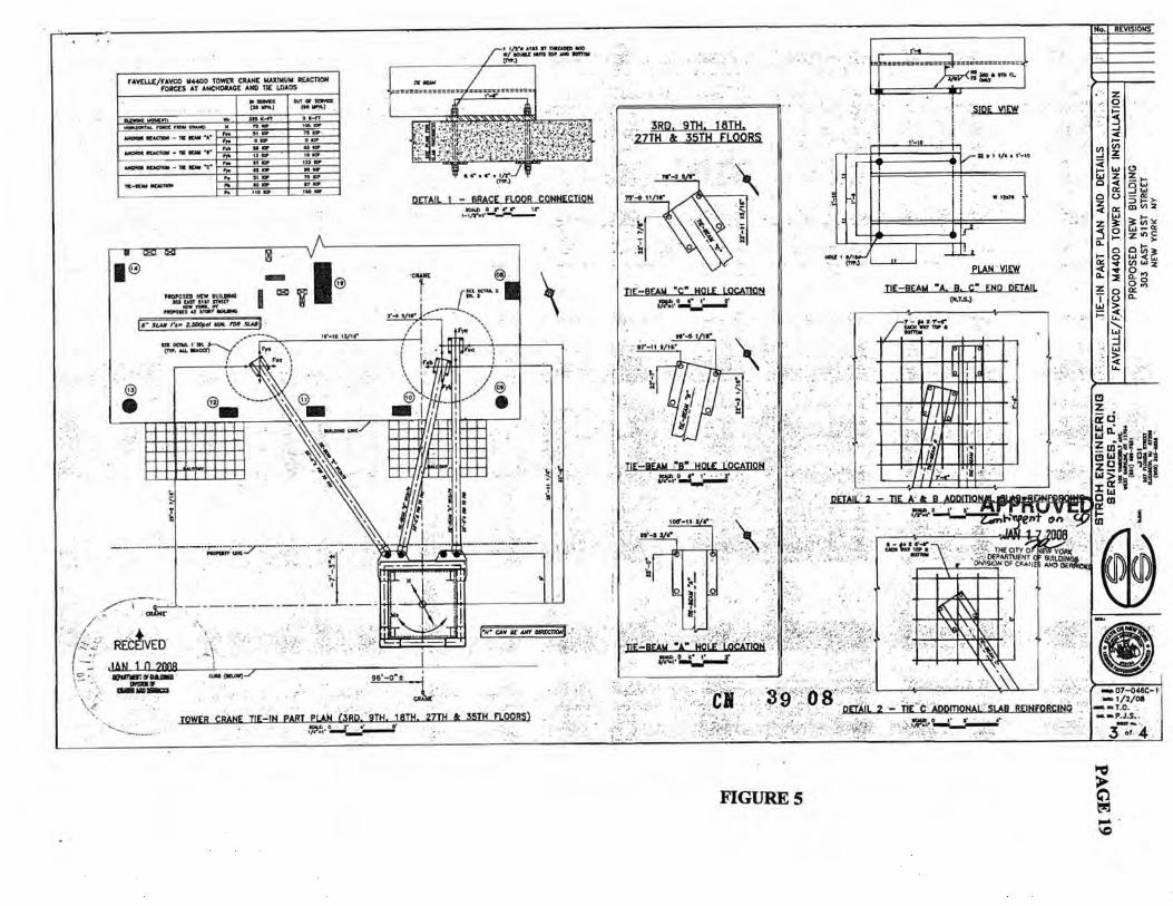
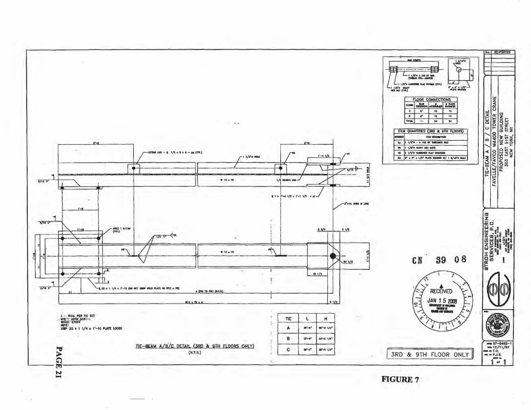
The crane mast was laterally supported by steel beam ties connected to the building’s structural
slabs at the 3rd and the 9th floor. The ties at each floor consisted of three wide flange beams
fastened at one end to the building floors and at the other end pinned to a square steel collar
surrounding the mast of the crane. The tie beams on the 3rd and the 9th floors were installed
using a mobile crane at the time of the initial installation of the crane. The employees were
installing the tie beams on the 18th floor without using any mobile crane. This was the first time
the employees were installing the tie beams in this manner by using the crane itself.
As the building construction progressed, the building increased in height. At the time of the
incident, the 19th floor was already poured with forming in progress for the 20th floor. Under the
19th floor, there was one level of shoring and two levels of reshoring. Subsequently, on the day
of the incident, the crane height was also increased by four sections to a total height of 250’. The
crane was then placed back in operation. The next thing to accomplish was to connect the mast
to the 18th floor slab through the tie beams to provide lateral support to the mast. The process to
5
accomplish this task was first to erect a steel collar around the crane mast by suspending it from
the mast steel members above the collar. At this time, the collar would not be physically
connected to the mast but will have an approximate gap of 2” between the collar and the mast.
Then the collar to the 18th floor was to be connected by three tie beams. One end of the tie beams
would be fastened to the structural floor slab, and the other end placed in the collar pocket and
pinned. The crane mast would then be re-plumbed, and the gap between the collar and the mast
would then be eliminated by tightening the blocks to provide a tight fit. There would be no
positive connection between the collar and the mast. The tie beams were to transfer lateral loads
only, and not the gravity loads.
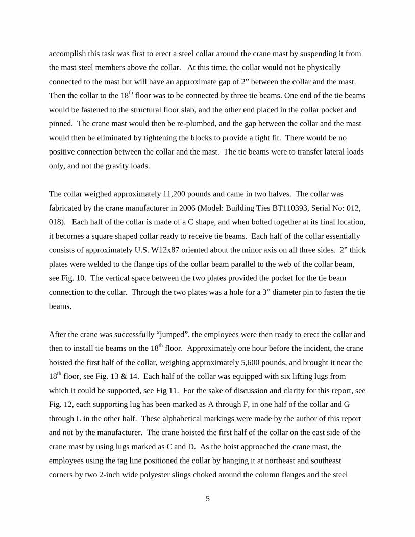
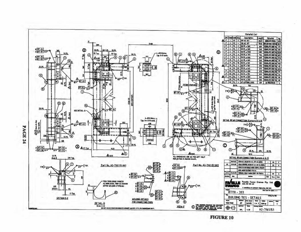
The collar weighed approximately 11,200 pounds and came in two halves. The collar was
fabricated by the crane manufacturer in 2006 (Model: Building Ties BT110393, Serial No: 012,
018). Each half of the collar is made of a C shape, and when bolted together at its final location,
it becomes a square shaped collar ready to receive tie beams. Each half of the collar essentially
consists of approximately U.S. W12x87 oriented about the minor axis on all three sides. 2” thick
plates were welded to the flange tips of the collar beam parallel to the web of the collar beam,
see Fig. 10. The vertical space between the two plates provided the pocket for the tie beam
connection to the collar. Through the two plates was a hole for a 3” diameter pin to fasten the tie
beams.
After the crane was successfully “jumped”, the employees were then ready to erect the collar and
then to install tie beams on the 18th floor. Approximately one hour before the incident, the crane
hoisted the first half of the collar, weighing approximately 5,600 pounds, and brought it near the
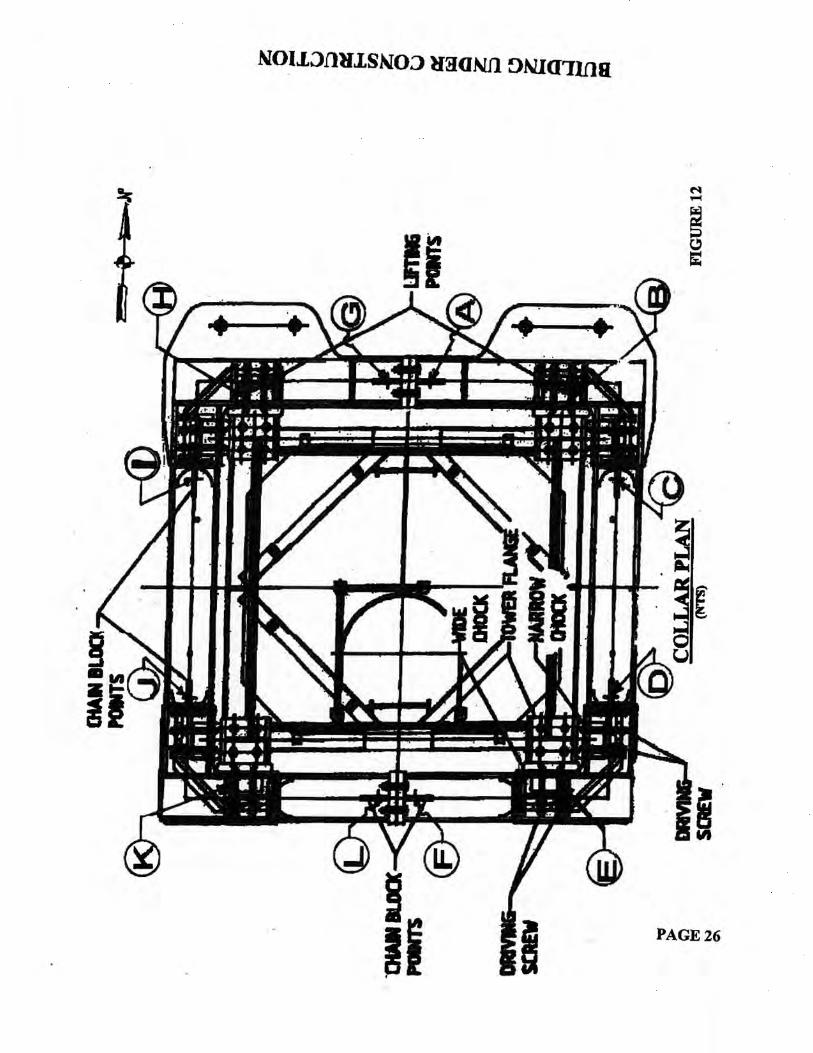
18th floor, see Fig. 13 & 14. Each half of the collar was equipped with six lifting lugs from
which it could be supported, see Fig 11. For the sake of discussion and clarity for this report, see
Fig. 12, each supporting lug has been marked as A through F, in one half of the collar and G
through L in the other half. These alphabetical markings were made by the author of this report
and not by the manufacturer. The crane hoisted the first half of the collar on the east side of the
crane mast by using lugs marked as C and D. As the hoist approached the crane mast, the
employees using the tag line positioned the collar by hanging it at northeast and southeast
corners by two 2-inch wide polyester slings choked around the column flanges and the steel
6
angles of the K braces. Each sling was attached to a come along which was, in turn, connected
to chain fall fastened to the collar lifting lugs marked B and E. Both slings used at the southeast
and northeast corners were manufactured by LiftAll.
In a similar manner, the other half of the collar was then brought by the crane on the west side of
the crane mast, again lifting at lugs marked I and J, see Fig. 12. This half of the collar was also
hung by two 2” wide polyester slings on the northwest and southwest corners using lugs marked
H and K using the same arrangement described above. The sling at the northwest corner was
manufactured by LiftAll Company. The sling at the southwest corner was manufactured by
Metro Wire Rope of Union, NJ. When both halves of the collar were leveled and plumbed, the
two halves were bolted together with four bolts on the north side and four bolts on the south side.
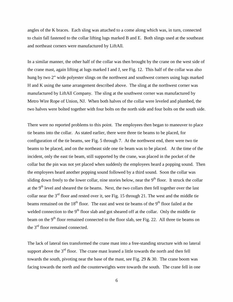
There were no reported problems to this point. The employees then began to maneuver to place
tie beams into the collar. As stated earlier, there were three tie beams to be placed, for
configuration of the tie beams, see Fig. 5 through 7. At the northwest end, there were two tie
beams to be placed, and on the northeast side one tie beam was to be placed. At the time of the
incident, only the east tie beam, still supported by the crane, was placed in the pocket of the
collar but the pin was not yet placed when suddenly the employees heard a popping sound. Then
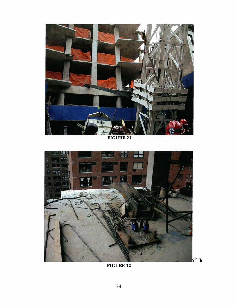
the employees heard another popping sound followed by a third sound. Soon the collar was
sliding down freely to the lower collar, nine stories below, near the 9th floor. It struck the collar
at the 9th level and sheared the tie beams. Next, the two collars then fell together over the last
collar near the 3rd floor and rested over it, see Fig. 15 through 21. The west and the middle tie
beams remained on the 18th floor. The east and west tie beams of the 9th floor failed at the
welded connection to the 9th floor slab and got sheared off at the collar. Only the middle tie
beam on the 9th floor remained connected to the floor slab, see Fig. 22. All three tie beams on
the 3rd floor remained connected.
The lack of lateral ties transformed the crane mast into a free-standing structure with no lateral
support above the 3rd floor. The crane mast leaned a little towards the north and then fell
towards the south, pivoting near the base of the mast, see Fig. 29 & 30. The crane boom was
facing towards the north and the counterweights were towards the south. The crane fell in one

7
piece striking the building, known as 300-304 E. 51 St., across the street. The crane mast was
sheared off at the roof of the building with the top portion of the mast including the crane super-
structure separating from the lower portion of the mast. The top portion of the crane
somersaulted and landed one block away over another building, see Fig. 32 & 33. The tie beam
hoisted by the crane which was placed in the pocket of the collar but not yet pinned flew over
306 and 308 E. 50th Street buildings, damaging both structures.
At the time of the incident, there were six Joy employees on the crane mast assisting with the
placement of the tie beams. Five were killed, and one was seriously injured. The crane operator,
also a Joy employee, was also killed. In addition, a civilian located in the building where the
crane superstructure landed was also killed. The president of Rapetti, located on the 18th floor
assisting with the placement of the tie beams, sustained serious injuries.
Analysis:
Based upon review of available information, eyewitness statements, and all documents, the use
of polyester slings and the manner they were rigged around the mast column, resting in the V
shape made by the column legs and the steel angle braces, warranted further engineering
evaluation by OSHA. It was readily acknowledged that none of the slings were protected against
sharp edges of the column legs and the steel angle legs. OSHA proceeded to determine whether
the slings placed in the V-shaped crotch could have a significantly reduced capacity to support
the load.
There were four slings used to support the collar. All were 2” wide polyester slings, 6 ft. long.
Three were manufactured by LiftAll Company, and one was manufactured by Metro Wire Rope.
Post-collapse examination of the slings revealed that the Metro sling was used at the southwest
corner of the collar, and had a rated capacity of 6,400 pounds, 5,100 pounds and 12,800 pounds
under vertical, choker and V basket configurations, respectively, see Fig. 23. The Metro sling
bore a serial # Sample-028. The Liftall slings had a similar rated capacity i.e., 6,400 pounds,
5,000 pounds and 12,800 pounds under vertical, choker and basket configurations, respectively,
see Fig. 24. Two LiftAll slings, type EE2-802D, bore serial numbers 1049068. The other
8
LiftAll sling had a serial number, 1020620. The come alongs, Series 653 hand operated load
hoists, were manufactured by Columbus McKinnon Corporation of Amherst, NY, and had a
rated capacity of 3 tons each. With a usual factor of safety of 4, each sling, if choked properly
and in a good condition, would provide an ultimate failure capacity of approximately 20,000
pounds. Given the weight of the collar to be 11,200 pounds, four slings, if all are supporting the
collar weight equally, would provide a factor of safety of approximately 7 or more. However, if
the slings are not choked properly, and if one of the four slings fails, the capacity of the
remaining slings would be greatly reduced.
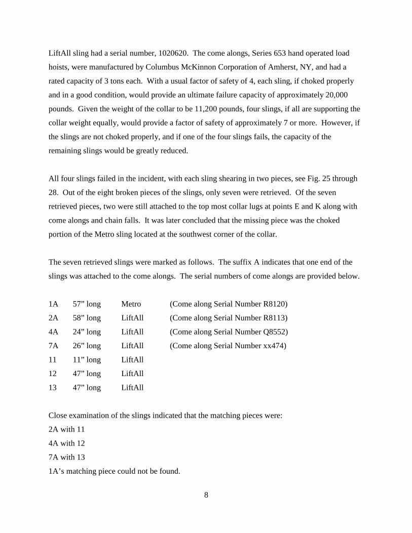
All four slings failed in the incident, with each sling shearing in two pieces, see Fig. 25 through
28. Out of the eight broken pieces of the slings, only seven were retrieved. Of the seven
retrieved pieces, two were still attached to the top most collar lugs at points E and K along with
come alongs and chain falls. It was later concluded that the missing piece was the choked
portion of the Metro sling located at the southwest corner of the collar.
The seven retrieved slings were marked as follows. The suffix A indicates that one end of the
slings was attached to the come alongs. The serial numbers of come alongs are provided below.
1A 57” long Metro (Come along Serial Number R8120)
2A 58” long LiftAll (Come along Serial Number R8113)
4A 24” long LiftAll (Come along Serial Number Q8552)
7A 26” long LiftAll (Come along Serial Number xx474)
11 11” long LiftAll
12 47” long LiftAll
13 47” long LiftAll
Close examination of the slings indicated that the matching pieces were:
2A with 11
4A with 12
7A with 13
1A’s matching piece could not be found.
9
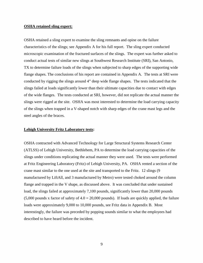
OSHA retained sling expert:
OSHA retained a sling expert to examine the sling remnants and opine on the failure
characteristics of the slings; see Appendix A for his full report. The sling expert conducted
microscopic examination of the fractured surfaces of the slings. The expert was further asked to
conduct actual tests of similar new slings at Southwest Research Institute (SRI), San Antonio,
TX to determine failure loads of the slings when subjected to sharp edges of the supporting wide
flange shapes. The conclusions of his report are contained in Appendix A. The tests at SRI were
conducted by rigging the slings around 4” deep wide flange shapes. The tests indicated that the
slings failed at loads significantly lower than their ultimate capacities due to contact with edges
of the wide flanges. The tests conducted at SRI, however, did not replicate the actual manner the
slings were rigged at the site. OSHA was most interested to determine the load carrying capacity
of the slings when trapped in a V-shaped notch with sharp edges of the crane mast legs and the
steel angles of the braces.
Lehigh University Fritz Laboratory tests:
OSHA contracted with Advanced Technology for Large Structural Systems Research Center
(ATLSS) of Lehigh University, Bethlehem, PA to determine the load carrying capacities of the
slings under conditions replicating the actual manner they were used. The tests were performed
at Fritz Engineering Laboratory (Fritz) of Lehigh University, PA. OSHA rented a section of the
crane mast similar to the one used at the site and transported to the Fritz. 12 slings (9
manufactured by LiftAll, and 3 manufactured by Metro) were tested choked around the column
flange and trapped in the V shape, as discussed above. It was concluded that under sustained
load, the slings failed at approximately 7,100 pounds, significantly lower than 20,000 pounds
(5,000 pounds x factor of safety of 4.0 = 20,000 pounds). If loads are quickly applied, the failure
loads were approximately 9,000 to 10,000 pounds, see Fritz data in Appendix B. Most
interestingly, the failure was preceded by popping sounds similar to what the employees had
described to have heard before the incident.
10
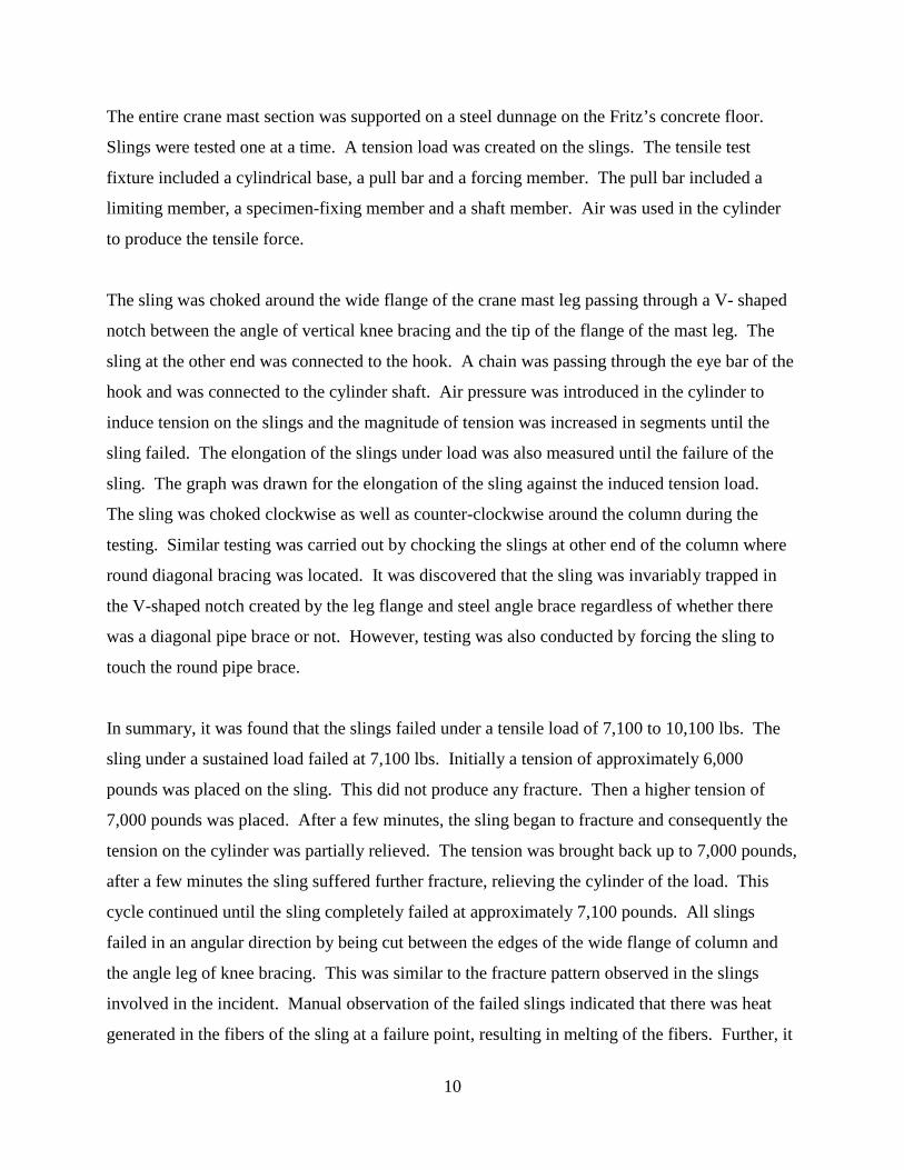
The entire crane mast section was supported on a steel dunnage on the Fritz’s concrete floor.
Slings were tested one at a time. A tension load was created on the slings. The tensile test
fixture included a cylindrical base, a pull bar and a forcing member. The pull bar included a
limiting member, a specimen-fixing member and a shaft member. Air was used in the cylinder
to produce the tensile force.
The sling was choked around the wide flange of the crane mast leg passing through a V- shaped
notch between the angle of vertical knee bracing and the tip of the flange of the mast leg. The
sling at the other end was connected to the hook. A chain was passing through the eye bar of the
hook and was connected to the cylinder shaft. Air pressure was introduced in the cylinder to
induce tension on the slings and the magnitude of tension was increased in segments until the
sling failed. The elongation of the slings under load was also measured until the failure of the
sling. The graph was drawn for the elongation of the sling against the induced tension load.
The sling was choked clockwise as well as counter-clockwise around the column during the
testing. Similar testing was carried out by chocking the slings at other end of the column where
round diagonal bracing was located. It was discovered that the sling was invariably trapped in
the V-shaped notch created by the leg flange and steel angle brace regardless of whether there
was a diagonal pipe brace or not. However, testing was also conducted by forcing the sling to
touch the round pipe brace.
In summary, it was found that the slings failed under a tensile load of 7,100 to 10,100 lbs. The
sling under a sustained load failed at 7,100 lbs. Initially a tension of approximately 6,000
pounds was placed on the sling. This did not produce any fracture. Then a higher tension of
7,000 pounds was placed. After a few minutes, the sling began to fracture and consequently the
tension on the cylinder was partially relieved. The tension was brought back up to 7,000 pounds,
after a few minutes the sling suffered further fracture, relieving the cylinder of the load. This
cycle continued until the sling completely failed at approximately 7,100 pounds. All slings
failed in an angular direction by being cut between the edges of the wide flange of column and
the angle leg of knee bracing. This was similar to the fracture pattern observed in the slings
involved in the incident. Manual observation of the failed slings indicated that there was heat
generated in the fibers of the sling at a failure point, resulting in melting of the fibers. Further, it
11
was observed that there were three angular cut marks or impressions where the sling touched the
other (remaining three) flanges of the wide flange legs.
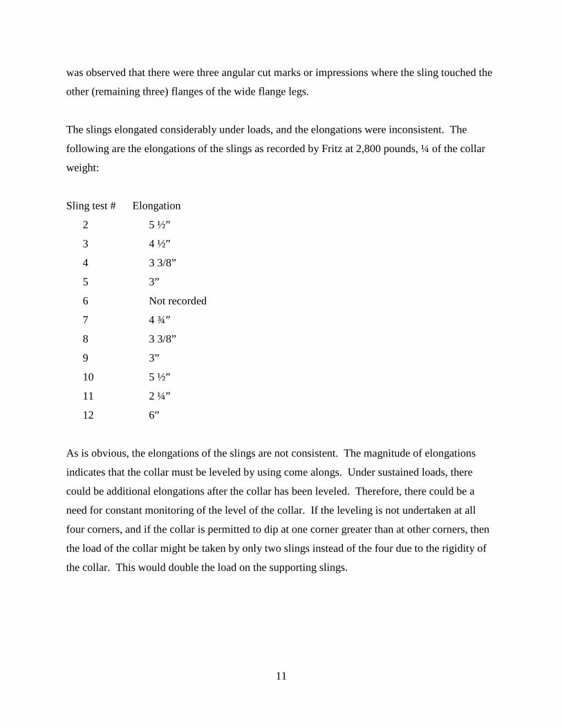
The slings elongated considerably under loads, and the elongations were inconsistent. The
following are the elongations of the slings as recorded by Fritz at 2,800 pounds, ¼ of the collar
weight:
Sling test # Elongation
2 5 ½”
3 4 ½”
4 3 3/8”
5 3”
6 Not recorded
7 4 ¾”
8 3 3/8”
9 3”
10 5 ½”
11 2 ¼”
12 6”
As is obvious, the elongations of the slings are not consistent. The magnitude of elongations
indicates that the collar must be leveled by using come alongs. Under sustained loads, there
could be additional elongations after the collar has been leveled. Therefore, there could be a
need for constant monitoring of the level of the collar. If the leveling is not undertaken at all
four corners, and if the collar is permitted to dip at one corner greater than at other corners, then
the load of the collar might be taken by only two slings instead of the four due to the rigidity of
the collar. This would double the load on the supporting slings.
12
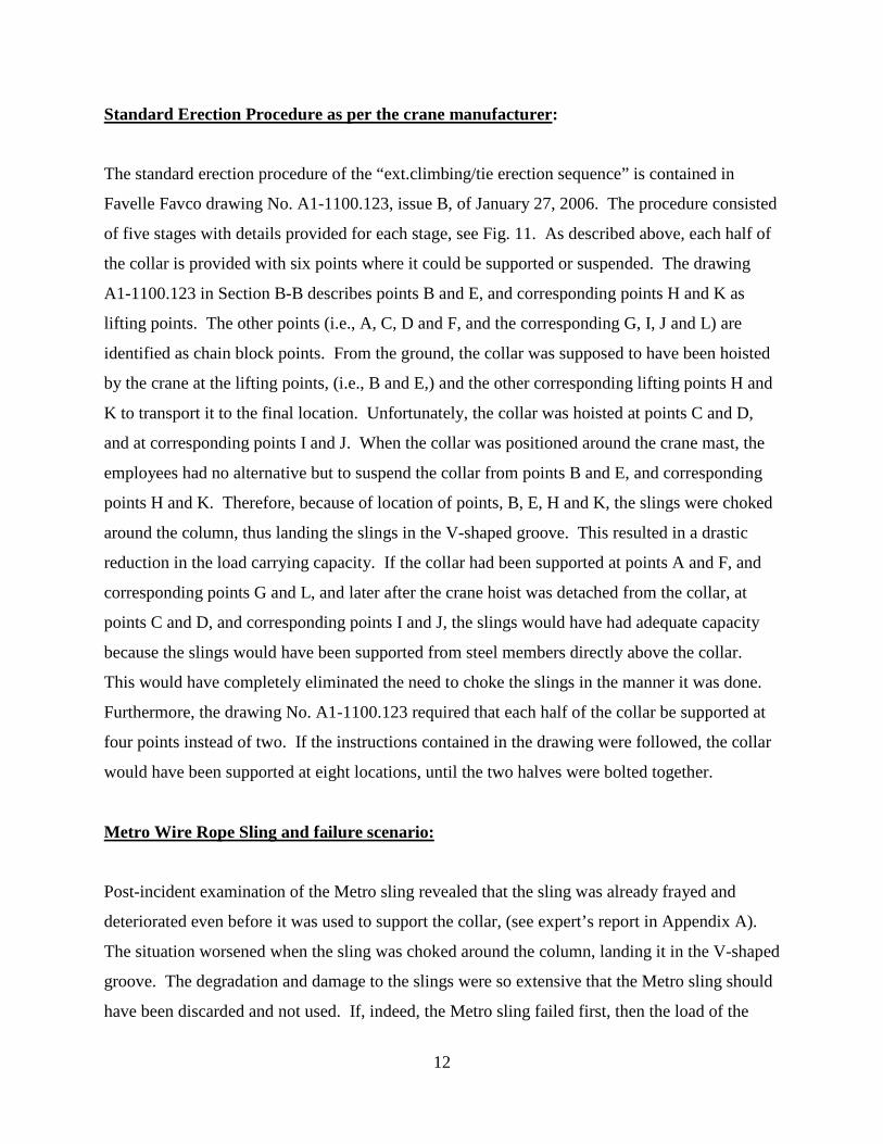
Standard Erection Procedure as per the crane manufacturer:
The standard erection procedure of the “ext.climbing/tie erection sequence” is contained in
Favelle Favco drawing No. A1-1100.123, issue B, of January 27, 2006. The procedure consisted
of five stages with details provided for each stage, see Fig. 11. As described above, each half of
the collar is provided with six points where it could be supported or suspended. The drawing
A1-1100.123 in Section B-B describes points B and E, and corresponding points H and K as
lifting points. The other points (i.e., A, C, D and F, and the corresponding G, I, J and L) are
identified as chain block points. From the ground, the collar was supposed to have been hoisted
by the crane at the lifting points, (i.e., B and E,) and the other corresponding lifting points H and
K to transport it to the final location. Unfortunately, the collar was hoisted at points C and D,
and at corresponding points I and J. When the collar was positioned around the crane mast, the
employees had no alternative but to suspend the collar from points B and E, and corresponding
points H and K. Therefore, because of location of points, B, E, H and K, the slings were choked
around the column, thus landing the slings in the V-shaped groove. This resulted in a drastic
reduction in the load carrying capacity. If the collar had been supported at points A and F, and
corresponding points G and L, and later after the crane hoist was detached from the collar, at
points C and D, and corresponding points I and J, the slings would have had adequate capacity
because the slings would have been supported from steel members directly above the collar.
This would have completely eliminated the need to choke the slings in the manner it was done.
Furthermore, the drawing No. A1-1100.123 required that each half of the collar be supported at
four points instead of two. If the instructions contained in the drawing were followed, the collar
would have been supported at eight locations, until the two halves were bolted together.
Metro Wire Rope Sling and failure scenario:
Post-incident examination of the Metro sling revealed that the sling was already frayed and
deteriorated even before it was used to support the collar, (see expert’s report in Appendix A).
The situation worsened when the sling was choked around the column, landing it in the V-shaped
groove. The degradation and damage to the slings were so extensive that the Metro sling should
have been discarded and not used. If, indeed, the Metro sling failed first, then the load of the

13
collar could have been supported by the two opposite diagonal slings, each supporting
approximately 5,600 pounds under static loading. With the impact factor due to dynamic
loading, and the contributing load of the tie beam, the slings could have reached the failure loads.
14
Conclusions:
1. The choice of using polyester slings to suspend the collar at four points was questionable
as they are subject to large elongations under tensile loads, thus creating a need to
constantly monitor and level the collar.
2. The collar was rigged improperly in that the slings used to suspend the collar were
choked around the vertical legs of the crane mast and was seated in the V-shaped groove
between the angle bracing and the flange of the crane mast leg. This significantly
reduced the load carrying capacity of the slings.
3. The slings were not protected against sharp edges for cuts and abrasions.
4. A deteriorated sling, which should have been discarded if proper inspection of the sling
was done prior to its use, was used to suspend the collar.
5. The crane raised the collar from the ground hoisting it at locations different from the
crane manufacturer’s recommendations. This led the employees to suspend the collar
from locations above which there were no horizontal members. This resulted in choking
the slings around the legs of the crane mast.
6. Each collar half was suspended at two points instead of at four points as recommended by
the crane manufacturer.
Crane Cofl~p!5.e Operations 3/16/2008 07:00
~81~~ "il'=" i;ocn F sc.t. !Jil
. l
- ...... ~, "Hcdl ~· r::::J ..... 'Io ....
'4 r..-a.- •• CJ~ ............ ..__ ..... -
FIGURE 1
PAGE 15
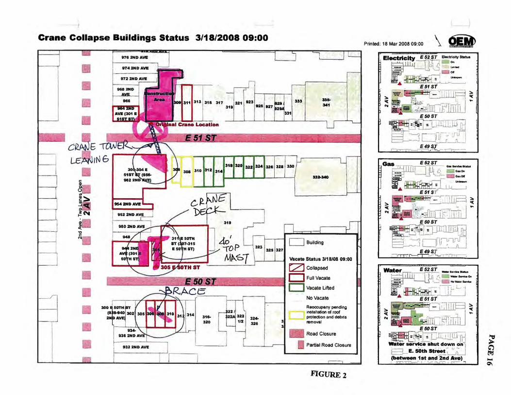
Crane Collapse Buildings Status 3/18/2008 09:00
c
~ ~
~~ ~::::. as.-_,1 o . ~N
~ .., c: N
W62NDAVE
S3a.340
Vacate Status 3/18/08 09:00
I:2:J Collapsed
r ..11""""="'" _____.- ___ :A:• ~ . ,, .I c:J Full Vacate
I
c:J Vacate Lifted
No Vacate
Reoccupany pending installation of roof protection and debris removal
Partial Road Closure
FIGVRE2
J
Printed: 18 Mar 2008 09:00 \ <iW
E52ST
::. · ~ ! ..
I--- - L - - .... ...., .. .,...,
1 ""' l_jl jlJ; [.• - - Guo. ••• ' ' l.J 'L.i:::: c::J Gao 011
..;< ,-j -~ ... :iffij.J~~
- .-:.7 -!ill=\ ::. ::. ~~- ~-- ~ ... ¥~ - - ..... ~ - -· ' pi" ........ F-'"' c-. - ~~;:{ITO 11 ~TIJ
E50ST
~r ='~ ~-Lj..::~J"'"[L:.,r-r-- _j tJ r4 ~ r-t[Jju"L.rSl c=:i---'""~.J L___j _ _,. ..__)u
E49ST ;-,,...-~,.,....~.-;-r,.---;
Water . E52ST _ .. .....,......,
~~ tfjr, _ __ ....... ""
-~ .. Nowaters.tvb
S ~~-,- JfL'i .& E51ST
::. ~c.JJl.l.lli---i ~ ~~--~
~ ~AL~irl~lj .. E50ST
~. ' .=~r~IW· I · · =d':i~= = L,rU-.L.!_t.:.J In M-: ~~ jl ~ .).,!
water service shut down on 1 8-E. sOth st~t ~~ (between 1st and 2nd Ave)
"r"'T"'1~- : . ~_,- """'Ll'-;- • ~ ;
~ g_? -Q\
.I i· . d
I I
I I -d
-d
I i . II
3flN3AY ON&
~. .
... ~ .. '
. I I . d
. . -
PAGE 17
-; . --r~J:~--· .:~*~-
.•· '; :;._, . .. ...,.
1!\ . ! """'"' I """"" ·- ' - !
':!
.... cAsr srsr srRccr f!'~~-=IDCII·TM ~
~ ,_. QC
..
~~~·iij
,. ' ,.
;' ~ ... , ."> ' . '(, .
f.~, ~~ RECEIVED < ·. ",\t-~· JAN 1 0 21i!l8 ,. :~ . e_, ~:- -~-,-"'\ MDII!SB!Iil* - ~- ··:· \ . ..,if / ..... /
~ . '.-..... , ~ ......_ ___ ::-~""_,. ..
'3 '9 c·s
FIGURE4
i
IW::-: I~
..Etm....YJ£Yl
1/4. f'UWIIIOa CIOf'l
@.nmJJ.....1 ICILC 0 t·~~ tr-t-t.rr-_,•--
APPROVED c,.,.~,. 0.. cJ)
L JANm n 1h \ J"' DE~~Jf!IT QF BUIDINO$ . •
MSION oF~ AHO OIRIIIicQ
....,..
HO.rREVISIO
I~ z -0
~ c -' 0~ :z: en <( ~
I~ .... z
0 <(
ti 0:: 0 ...,
en o:: .... rz j ~ a. a
·•I-
~
l!)
5~;; 5~>-..,cn:z
~~~-:Z:"'~ ·o ... :;:3~
~ ~ 0 :z a."'
~ 0~~~ ~ 0 Q.
m ~ ...,, CIJ.&J -< -' :z: -' :z: .... :::1 > 0 ~
I!J z iid 1.&1 • i!
- ·~ ':h ill i; ffi I;* ii_la. ze ~~·~l~r ~~,,! li9l! 01.&1 ~Ill 1-Ul
* -e· -o7-o4&C-1 -1/2/08
@SECTION B ··· •-•T.o.
c&ntP.J.S • -•u •• •• ,, .... ,.~ .. 2-.;-4
· ..
.··'
r AVf.US./rAVC!J W«<D Towtll CltANE loCAXIM\IN REAC110N foacD AT AHC;IIOtill£ AND t1[ LOADS
~-...,.,,.,._
( ...... , C'M..,..) .. US""" · 1- 11'
~A&.t'OIIICniiWOWIIP . .... ..... AIICtiiiii·ACTIOit - •ICMII•A• ·~
.... ..... .... .... ...--...nw- ..... · .. ... .... .... , .. ..... AMCMIII~ -TII IOW~
... '"'" ...... .... ... ,, .... .... .......... ~ .. ...... '""' ..... DETAIL 1 - BRACE flQQB COHHi:CJlON
.@ fmPOSftl NlW tui.CING
MJIAif 1111'"'"' IU'tr1WII'.Illt
.... OIA,JIT'Cil'f--I
~ . -CBI vi@
ICoiUI: o .. -"' t:" 1r 1-i.,...-1._-
\ -eullt @
i 1"""'"'' . .... j ---J'"- Y"'.,- . .... ...
.> . I ... ..,. ',
\ \
,. ...... ----..., ,_.•10 •.yu;· 1 ~~~~~/ I '~
... @
' . . \
' \
@ -L---mm+l+~- --:-, ---:--~ ,_ .... "". ~~\ .
• "'• ' A. ·:;· · '\:~~~-- - ·
- '\:' ~ •
i ~~
I /@)
_.-' . .. •_:
• .~ I ' •,
---~ · -
' ~---·--··-'-·l-·-·:·;;;;;-~::-~-';~ ,:-~'7- • -tl. ·.~· .\f-t ·1- ····· I
;... I
- --·-_-~_ . \ . '
.-.
- · f •
,;.::. ..
.-::. ·' -~-:---- ---------:---- ---tllr·· , 11 11 ":tfl ~ED . \ .· •, . ·;;. ~;·,, ~~~ ":~;-'":1t~';\
t--:: .!AN 1 0 2008 . I · · ~ ~ - - __ .. _ .. _7 96·-o·t L.
I • ' -Of , .. -, :·; ,_ ~~~ ,- .. -··.' ~~ et ·.•,' .. .. .
-.~ - .. TOWER CRANE TIE-IN PARI PV.N <JBp: 9TH, 181}!. 27TH &: 35TH FlOORS) ....... '--~--- . ... ' ,~-~ ..
·:;i. '{ ~ -::".~. :-:· ,;· . - .
~ .·<;:· :' . . . ,. ~ .,
lo.l RViSIONS .
... ·-:/.·.' .. ·,.:-.· ; :..: ::&·· ·.~ ~- -- . ":·'· ::.•eTMft.
• '· IZ
.. · . i' SIDE VIEW 0
..... 3R(}. ·9TH; 18TH • ·"; 27TH a: 35TH fLOORS
',-'. I . I
I :· j ·· · ..
5 t ..J
-4: ,_
· · 1.;,: :.
l-.·:~
;:"1r.¢_.:~·- ~ .i- ·
... , . ··~·
. :.~\ ;· ~
!~:~-?: ··.· ···
11•1 ,, •• ,._,.
__ ,;::?_\· .. - .
- .... .A'8. . • w ,,.
- ~
~ en ~
< ... ,_ toJ z Q -4: ~
Q u z :<( ~
C!l
~l;j ..JW -a: :::>o->ID VI :Z
,.) ... . z -~
-~
... ::11: ~:;; )<
w-'" Z"'c
Tit BtAhl •A. B. c• END DETAIL (II.T.s.)
: I
j 0 a.. ....
0 t-o ~ "<t <C( "<t a..::::E
~ 0 I u ... >
>-
f;l~~ en ... :z
~~ ~ .... a..
/.
, .... ,. • . ,.-c"' ~-J"1111"•
; ·. t;::: -4: Lo.: ....... ...
' ' ::l LoJ >
. .. ·· ~~;• .:, ' ·-<,~ ,, _ L· I~ rn-·,.\.-''
::; 1 .. rwn ...... .. .
; .
~<z~~:-~ . ; .... •, ~ . :
·_:_./ .. :,:_:~:~;c~-~ -::--~_::- .~~~~~~;~,..-$~~>{~~? ' . - ~-·~:~~: .. ::_ ·:·:· : .. _:_ ·-:~-~ -.-: -:·:(:;:~ :. : • _. .•• . ~ ;--: :. . :.:.. ,,., ., ..... . . . DpAIL 2 • Tit C" AQD!T!ONA[i' SLAB RE!NfOBCINO ..
. ::~~z@:f·.,_.. ·ft::_;·:~·:j/:·;~,_:;·~~,.{:.£-K~i/- ·,_ , -,_~.:~~~:~.:.....r · :. ... ;: --~·,:-~, :
FIGURES
-
-w ..... 07-0<16!:-1· --1/2/01
-..t.o . ... -..P.J.S~ . --·· ·- .. ,3. or.·4 ·.
~ ~ .... \C>
AN '>!!lOA M3N !33!1!S !SlS !SY3 £Of
DNIOllnS t,\3N 03SOdO~d
NOilVllVlSNI 3NV~:> ~3M01 OOttVi O:>AV.:I/3113AV.:I
121 . --~ ·
·J u
n_ I l;! - -· z f T . ... 1=-
~ ! -...
!i " . -~
" 0
~~ ...
~ !i ~ ... ::I
" ~ ~~ 'i ! ~§ ; ::I
~ •II ~
~ I! I
t -
I .
"
" . " ~
~
• 'R . = a . ~
~
"
3ln03HOS dl'inr ONV SN011VA313
1: 1-i = II -
" . .
. . I ' .
• . . " • I d
~ ~ -
" I ! ~
& ~ ' . , I '>l != ~ ! ! f 1:) § ... i {-· -~~l, • = Is . @~jt . . '-
: • !i .\ ,. I \~
.. ~ •i \;; . i e~ - ':.
iii ..
" .
~;J~ --~- · . : :e··~J~ bq~,.-; ·. 'M'fl......,AIIU ; - - · o- .... a.. ...a.
":J.-d '.S301A'tl38 .. ,_ ' ... ~ .,. fll-.1 '' ?' EINI'ti33NIEIN3 HO't!J.S . · i . • - · ·1 f ,':;
PAGE20
. ... .... - ~~~\-
·, ·
~ : · .. I - • .
·->. ·-/·;~ --~ -:-· ·'
. -
-. .··;.
l -~~
·- ·
0
,._, r ...
;wo-t •t•••••-,.<m-1 !' 1/l"- MOU / .. , .... '" -v' I
~--· r '"l----------- --·- --- t-· - - - - L - - ----· ---P.l I /--~~- i ., - . u_,_..,....~• ---~
~ • 11• 71 vl....,...._J /,/ ,, .. ., "' I ! :
I ! ! ,_/ t t .. !·-· 1/2 • ,._, t/J - ,
I I I i i /J•IIMLIDUilllft
i 1'-1 i i 1 i i I
"" v -~ ! 1 I ·-·· i./ Hou t t/IW • f i tV• ''" ,,.,_,
~"'· J. --~-'--~ ' . I
T . . i i : I
. --~------ ~--~---~--!\1__- -4~ i i ---- s . -·-· --!----------~- --I I ~
,:. / .
1.~- - _ __._ ~ . I It t/4 ., / .I ~~ .. , .. ··-··, .. lOOT_ ............... ,.,
r
"" v II L (PoliO "'I (M.T.i.)
i ........ ··~
I - REQ. Pt:R n£ SET
· -- ~~;-~~~>~. · 1181!:: S1IP 22 X I 1/4 x 1'-10 PIAl!: LOOSE
nE·
I L
1 .. :.~1/1" A. ...,. -B I JS'- ... (34"-J ,,,.
-
w · ... ..r..u-:~ FLOOR CONNECTIONS
,_ ..... -I- .e.= -' ,. ,
" I .. ll II
TOTAl. - .. .. ITEII QUANTmES JRD I< gTH FLOORS ...... ,.,._... .. I 1/r'# - " IN U -.cADQ toO
" I t/1('11 Ht,.., 111)1. US .. 1 1/'1"- HAIDOP fUJ' "'AIHEII
14 I" • r a 1/r 1'\Alt WAIMDI W/ 1 1/""11 HOU
CN 39 08
No.I REVISIORS
1!1 z «ti
C>
~w 9w __ , ffit;;~
LLI' LLI a.~t I ~ gj~~-~! J i r: [!J 1.&.1 : ~~ Diia z9.§"''1~~~ ~~!l iii!
LLI li! w I ID
* ,. I,.. .. ,, .. ""C' TIE !!£AM AIB/C PETAIL (JRD ~ 9TH fLOORS ONLY)
> (N.T.S.) I c •I ...... I I I 3RD & 9TH FLOQR ONLY u -~ ~ 1~1
'-----~
N ioo-0 FIGURE7
PAGE22
---:i--~~
&.
~ ~ - _-_ - ~ I K ~ ~ N
.IIIJMJIII!.Z (.N
~ 4-MDIMII .. _...,._
1r -\r I .. I
.llmLIJIIIJZ
A.llll.M...t
' 11~ li '<J_
..III.6U .amu
1m
I ~ II
4J JmiJliiU
.IIWiliM.
~ .I&WJI
..... mtiiHHttypJ --·
DOIIIfstAUI'IallltA- •
··~ASIIII'CPTYL~-IIIPT. - -·--
: ..
Jl!lm tALL...- Am IIIDWU.1111[ IIAa.MUWTM
AIISDUIIA1!S11111Dt. Z.AU.UIIS?lti!IOWILOS~IIl-!lliiiiiiiiUSIII.n
WII.IIIWID.
I. AU. .IIIIlS ~I! .... --CDIIIIGSa 4.ITIICS -CA!UIIII''P'II'IIM.Irll- MATIIUI.
TUIIAIIJIY 1IIIIBIWICAL Alll OIIIOI.ItiiiRTI'EA1D. 5. MA101AL LST SHDVS M SIZD All) OIU •t .w.DW ,_
IIILD-AMTDL
LIIRI T11 II'C If£. I .. AI SIIB. ---TIP
lOIIIIITPAIITIMOWIUAIEIIf,_PM_ .. LPIIR wn.NIIIriUf .. IIIT IIRIT11 ...... ,lllf_. ........ 1 I.IL--~AWUl1lATlSTTAIII' t.2U .. WlUIIS AI linED.
W.lliiiWSIWI.IIliL,........_Y -·AaqoDAIII W1111Ama-Ll¥11.111RAIIMA5111AS'IIII IM111'11i11~0111111PAIIDTIII
Ill PIIRifCUSAUII!r'-TS-liTPIIIII.A,__ PIIRimtiii-.ISir_.'II'L_U._
PIIRIKUSAIIIIriiiTI-11li'I_U._ ,.IIMII AliAS USl r-e1111.-. AJo.1eiM1
FIGURE9
2118
Ill ~,5 = ~ "' i
~
~ ~
Ai.Mn
m. part No. A2-7161.151.001 Pi!rl No AZ-7161151.002
IYP.
17TJP.
lli.Im!I.H
.Qf.IAIIdj stAlE~~~
00 •1 «AU fiCIIDIAIIIII&I'IROIIIIll ASIIIfl PrYl1D 1-0EPl. ~
FIGURE 10

~ ~ N tJl
PAIIII.PIIIII
DIOCICS
~-SECDQNH
mliU l1..,_~ _,.A 'IIIII 01'- MIDCIUlaDILM TI!MlVD EATM TD 111 Tllll!lt. TilE- CIIWillltiiAU' -A TIS 1MI Pllc.EC'IIIIIMA!ICETS TOIIIIIET lfTliM-YIA TIIETI! .-. liE-R IIIU.UIItiiAU'IIIDIUI IE DIIEIITIII10 SPAI nt! TWOTIMII IllS a.DSDT 111 AID PMIII'II£-M IIUTIII CIIU.ARTEHAI.I' SIIDII.DI! IIIIIIITIDT11 IPA1111E OTID TWO.TIMII U6S WIIDtAAEI'UIITIIEST -ne--. ' . UllaiiC-'IIOIIOI'THI!CIIIICIISIIIIOIHTHI!CIIU.AITRIW.VDAIID_F_. ATIAQICIIIIIIRCFEACH CIIWRTIIHAI.I'-IIIDIUIII!A-AII)AIIIIEDai<.TIIE .. _CIIIICICSIIU.DII!I.OCATIDSOliiATII'WII!ARIII MMIEOI''IIIETIJWliU:GPUII&E.MIDM-DtDCISIIIIUIDili.GCATIDSO'IItATifiiiJ.II!AIIIIMroGESGFTIIETIMIIWI FUIIID AS-IISK'IIIIIt.-A. ·
U I'W Y llriUCT AU.aaDm 1IIE Cll.UISIY ._ 111-ICIIlVI 10-MAXIUICWIAICE II!TWQJI CIIIICIIS' '!CM1U!CISIIIJ.II!-~-TIE CIILLM11111Al'ftSM110 IIATTADIDTIITIETIMII-VIIHTIIE CIIIICIISIDITOPII!-TIIICIIIIIIUEOI' TIECGU.AR.PTIIEmnm.OI' THI!CIIWII WIIII!UNTIC..atsTTIMII P..._ --ATTADID 111M- llllll THE CIIWilliiiW.¥11 SIIIIIUII!II!DTED11111! LPT1D lft!'IITIE IIIDCICS -1111! 111111 TOI' IF THE CGU.AR Tl Ml'ID. CITIEIMilP THE CIJIIIIIIJIE 01' TilE CIIWJl WILli AIOYl TilE 1RM11T T1MIIP ..... -IIIIIIIATTAOB11111t1'- TIIIIITHt:CIILLNITIIW.WISIIU.DII!-TOII!I.PTUIVIIIIMCIIIIOC IIITHI!-IIIMCIIWRTaiiAL.U. -'IIECIJIIIIIIJIEIIIHOIIOIIAIET111£LGCATIDIDT-TIWI--A'!CMI Nm-IFAD-.m -·-----·--II.ISTII!USD.
t5 ATTAOINOEOIIAL UlllliiSUS 10 M-'lf 1.1'1111_. 01' TilE IIUTIII CIIUIITI! ... ,. SIWIIU!S.111 ~-ATMAIIXOI'TIIERJmSIIU.DIIITDICI!OU-MIDL\DIOU.SIIU.DiltATml'aiATWSTI
. T-CI&.
1.6--NIII1UIDMCIIWRTI!IIW'TOII-THI!T1MIILI8-IWS!OT11MCIIIIIIKTHB111T-I& AnMIIAS11PTOU.10MIIImi!OPMCIIWII111HALI'OI'SII'RWINTLDIIIII.TOIIUII.I-.TDURIT10PIIJ.11E CDUAIIIIAIIIIAIII -111'111W1111.115vmtM CtANl-I.FTIIIM COUAITEIIAU' AT--
\Til'T Mautacau.AI TIIWI'10TIE IIUIIIDATTACHI!lt!IIT 1'0111 111111110WIII-1111.FT111IIIIll MID TIE CRAIEItOIST II1TH Till-AT--
lUll
.- -1 --·· ., _ , _I ll It!"\\ Il L...
illlil!! 4.1ATTAQiaa&TOTHI!~TI!IIMSOTIIATITISLPTUIIIA UIIITM.L_TO_M-.ETI!TOTI£-1'11 -'AlAT111111L -IIACICIT,AIOTIIECIIU.AIIPII~IIACill.
U UHOG THE CRAIE .. OTIU SUITAaEUF11111DMCII LrTTHE 4.4 OIPUT IT AlliS 4.1 TOUlllliiOIH OUTER TI!IAIS. -.ETJEIMm-llmi!DIITSIIESPICTMPII ~lltACII!TIOITIIECIILAIIMIDTHI!I'IIATTAONIIT _,.011.,._
CMAIIIIIUICU
WliU t11111H THE OUIIR CIIWJl TE HAI.I' AT THE~ IIB1IIT Pill 11'11111POSITIIIAIOTI!IT111TIIETOIIIRIIIS101M'1111Tif --IIACICour. UATTACHAI'--CIIAIIIUICIC10WIIOPTIE4 IIIISID DWIIIUICIC POIIIS OR THE OUflll CIIWJl 11! IIAlP AID llllllltTTIIlOTIUEIIISTOMTliiiER .. C.C
u.-111E4CIIAIIIIlOCICS. TAIIlTIIELOAOOI'THEIIUTIII CIIWJl 11! IIALf OPP THE LI'IIIIIUIGIIO 111AT THEY CAlli! ~PIIOIIII'.
2."01PUTITAGISUTOU -TIIIICATETHEMIIICIIWII IIEHAI.I'.
WliU U USIIIOIMMIICIIlVI AO.UIT AU. D10C1S IIIII. EACH- .uT TIUOIISAT-Lm UTIIIIIIIII~-YOIITOM-LIIIS-AUm£ IUOII ... M. U-AU.IIIAIIII.OIIIS AOJAai!TlDTIIEIOlTID...cTIIL
------··--RMUI-~
- C11UAR TE HALF DIAlllllOIIIS
CIIWR
nAGU
Ll-'1111 DWIIIII.OCIIS 01 THE CIIUAR TE IU.VES RAISE Ia UMITIIMAS-IMliLTHEYARECIIIIIECII.YI.OCATIIIAT llEIIIIHTIDDII -Oil TIE TOWill U&S.
1.210l T liE ... MID IIUIIII Cll1AII 11! HALY!S TOI&liD, USIII THEIOlT-ANOIOLT-SPl<IPIIIIORTIIlRillYAIIT CIILAIIASSIIB.YORAIIIIIO.
Simi SECTIO_N B-8.
'TWEAI.~TDur.......-UIIItiiiWUI
-·-llltNIW''IPilllli --·---~- -...
• Dl_,,_ __ L __ Favell• Pavu Cl'ane. Pt)'. Ltd. • .................. . . ....... . _ .. ___ _ H440E
FIGURE 11
........... ... B
PAGE26
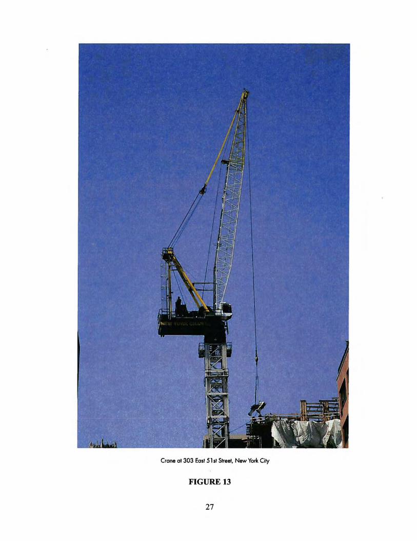
Crane at 303 East 51 st Street, New York City
FIGURE 13
27
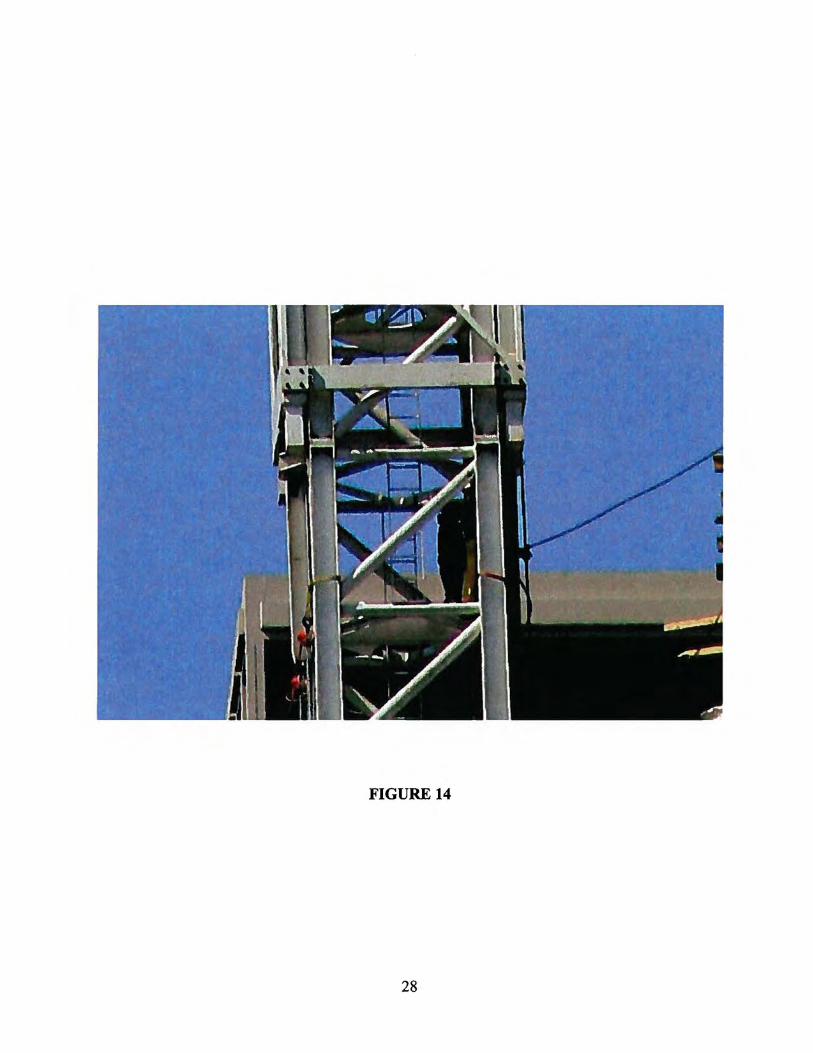
FIGURE 14
28
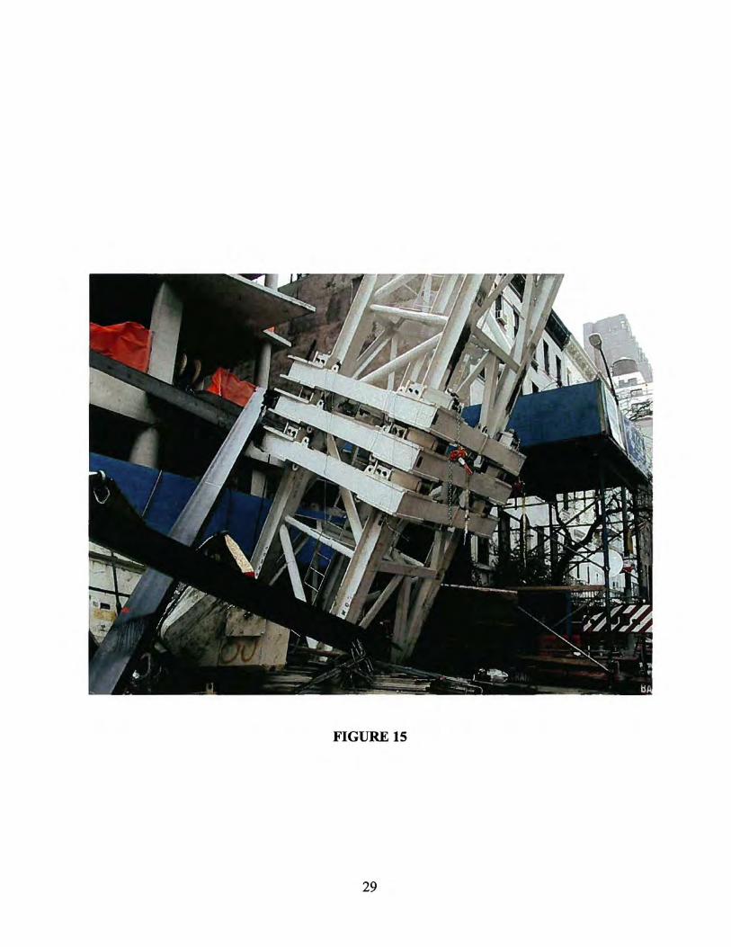
FIGURE 15
29
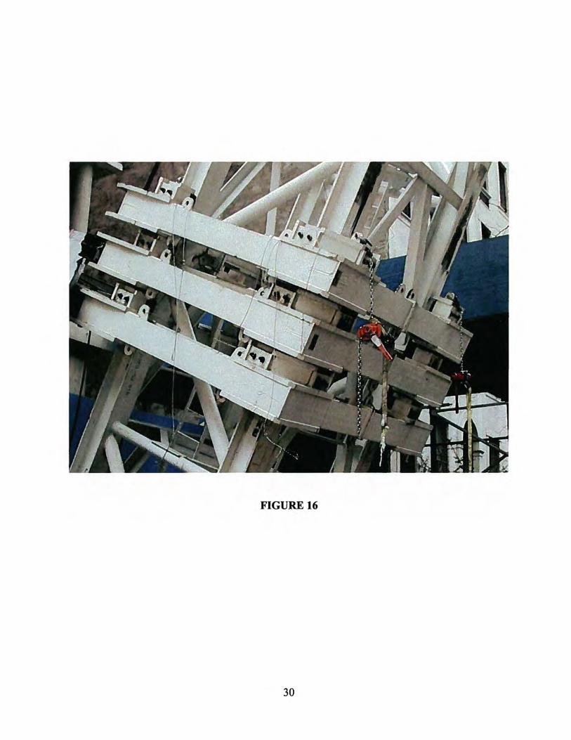
FIGURE 16
30
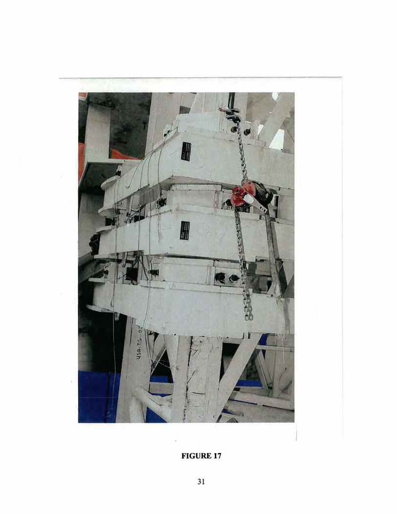
FIGURE 17
31
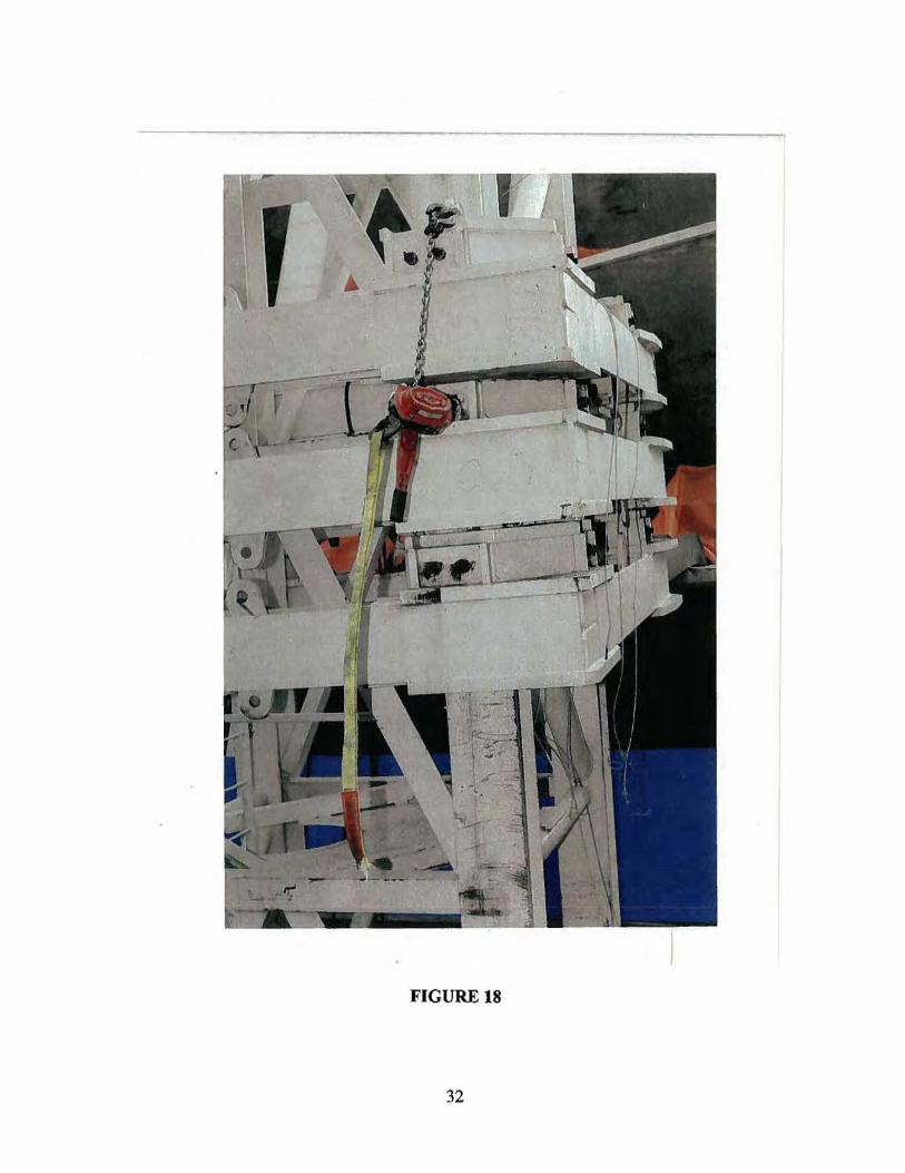
FIGURE 18
32
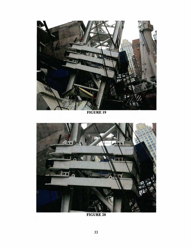
FIGURE 19
FIGURE 20
33
34
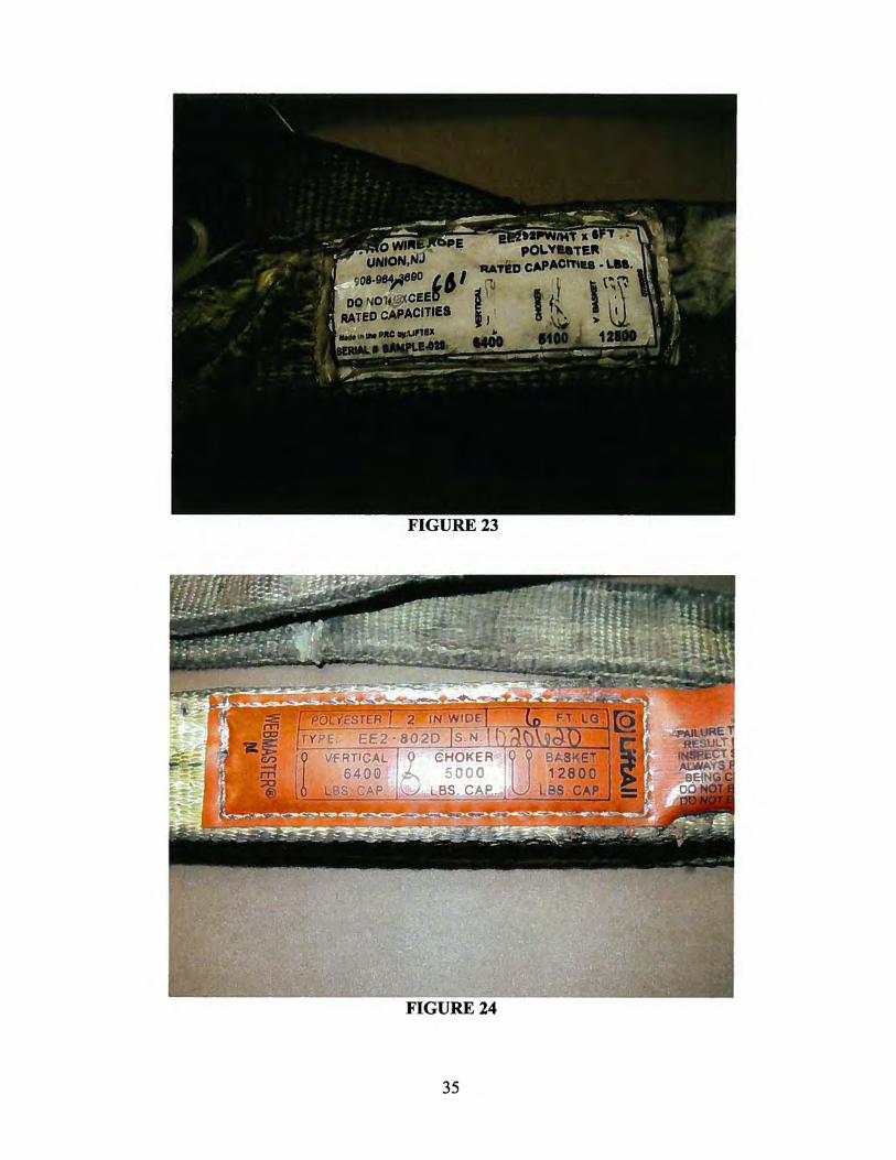
FIGURE 23
FIGURE24
35

36
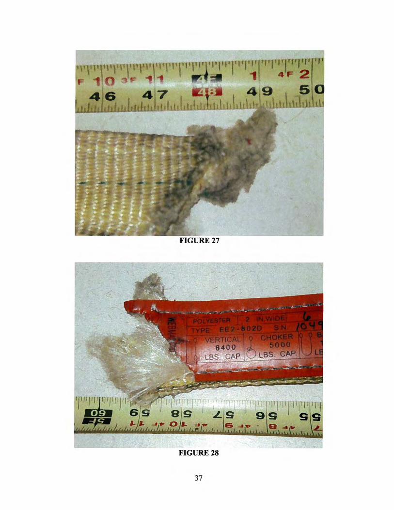
FIGURE28
37

FIGURE29 FIGURE30
FIGURE31 FIGURE32
38
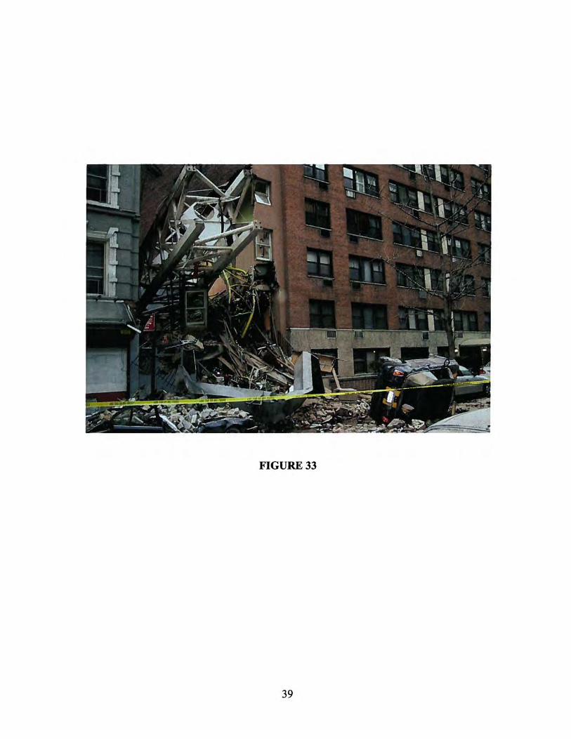
FIGURE33
39
APPENDIX A (No. of sheets 41 including this sheet)
APPENDIX A
SLING BREAKAGE INVESTIGATION FOR
DEPARTMENT OF LABOR- OSHA
CRANE COLLAPSE EAST 51 ST STREET
NEW YORK, NY
DONALD L. PELLOW- P.E. ENGINEERING CONSULTANT
AUGUST, 2008
406 WEST 50TH STREET • KANSAS CITY, MO 64112 • TEIJ'FAX 816 • 931 • 41 f 3 WWW.DONPELLOW.COM • [email protected]
SLING BREAKAGE INVESTIGATIO~ FOR DEPARTMENT OF LABOR- OSHA
CRANE COLLAPSE EAST Sl ST STREET- NEW YORK, NY
AUGUST, 2008
INTRODUCTION
APPENDIX A
On March 15, 2008, a tower crane on East 51 a Street collapsed while being erected against the side of a building. The tower carne structural sections had reached approximately 190' above ground level when the mishap occurred. As a 11,280 pound steel collar was being maneuvered into pace around the tower structure, the web slings holding the collar ruptured, resulting in the collar falling. The collar proceeded to descend to the ground, stripping a second collar from its connection to the building at about the 1 00' level, resulting in these two collars falling further and striking a third collar at about the 30' level.
The tower crane then became totally unsupported and began to topple, and finally fell against an adjacent building. The boom of the crane, along with the counterweights and cab, was catapulted across the top of several buildings, finally crushing through the top of a housing unit. This crane collapse resulted in the death of several persons and injuries many others.
Pellow Engineering Services, Inc. was contacted to review the evidence, with specific focus on the cause of failure of the four web slings supporting the top collar. The investigation was to include an examination of the rigging at the Manhattan New York OSHA office, followed by an inspection of several tower crane remnants and the steel collar in a warehouse at Pier #39 in New York City. Subsequent to this initial inspection, a more in depth arialysis of the web slings and testing of new, unused exemplar web slings was conducted at Southwest Research Institute, a Nationally Recognized Testing Laboratory in San Antonio, Texas. At the testing and evaluation at SWRI, multiple photographs were taken and a video recording was made of various inspection and testing procedures. Following this testing, another series of tests was conducted at Lehigh University using an actual section of the crane tower and exemplar web slings.
FINDINGS
INVESTIGATION AT OSHA & WAREHOUSE IN NEW YORK
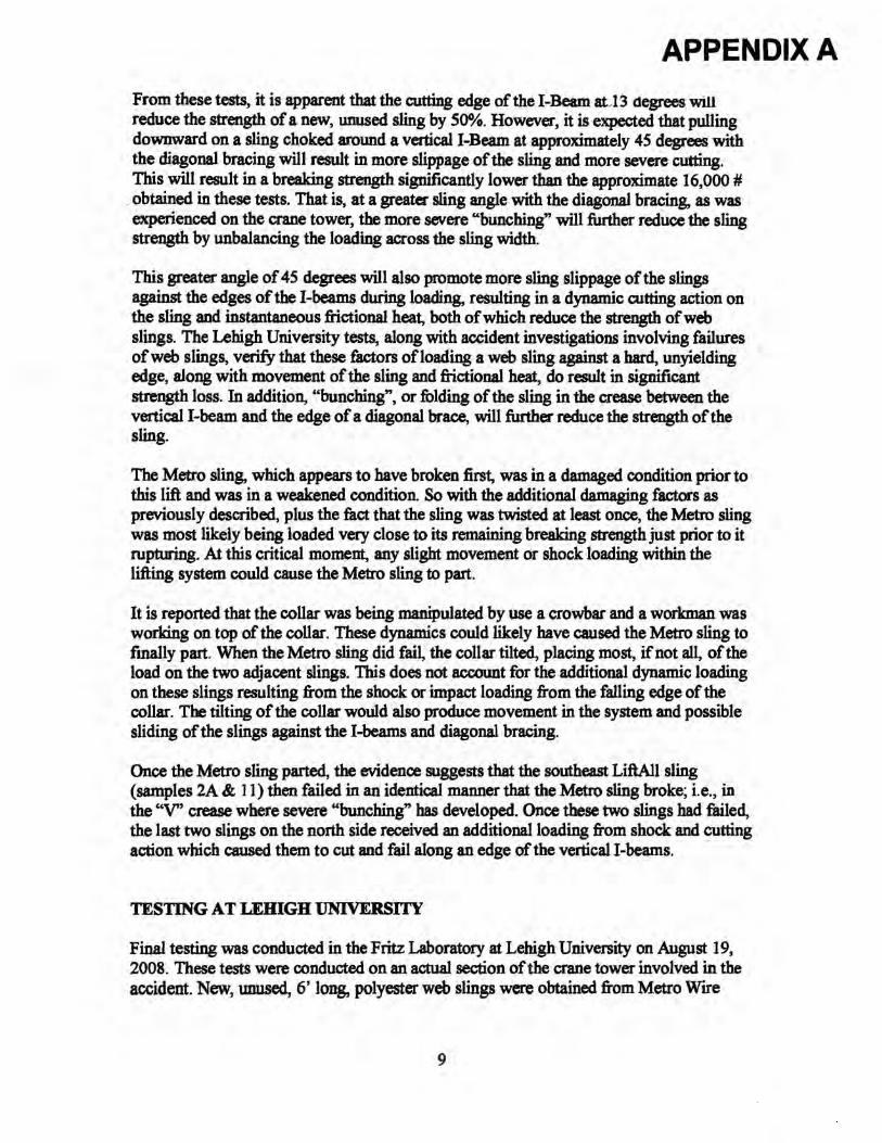
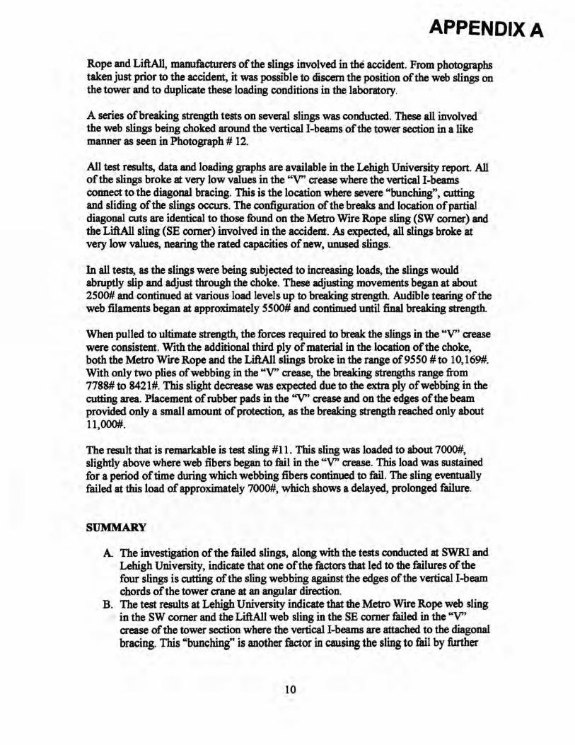
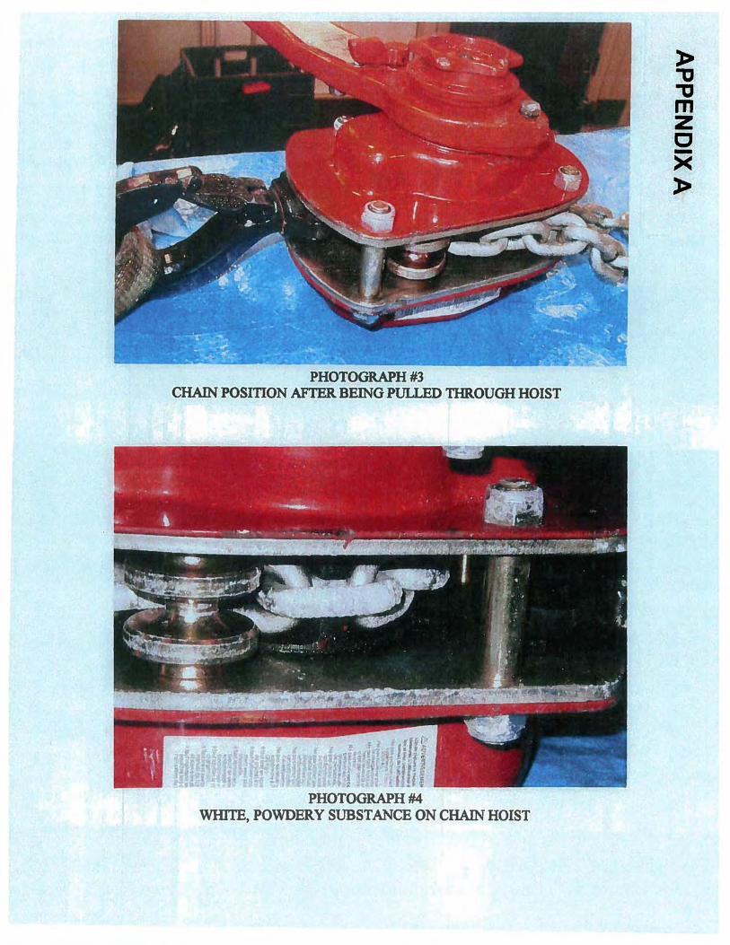
The initial investigation at the Manhattan OSHA office in New York City involved reviewing the evidence collected regarding the rigging supporting the steel collar. The four chain hoists and seven of the web sling remnants were inspected, measured and photographed (Photograph #1). Each of the chain hoists is rated at 3 tons, thereby
2
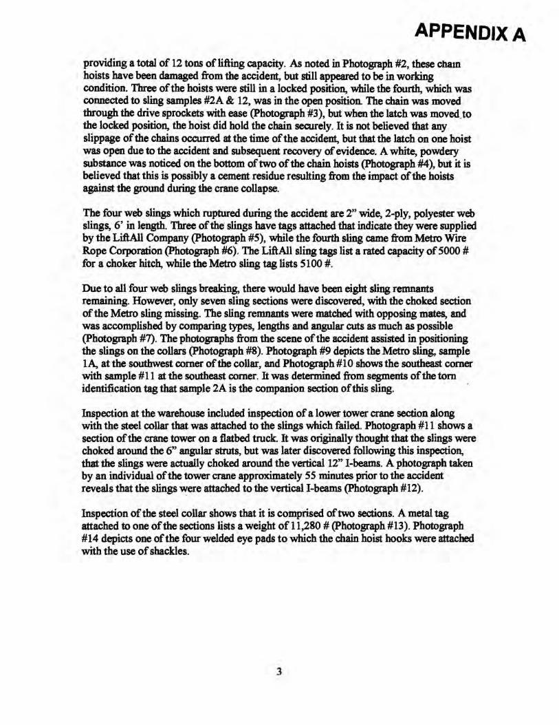
APPENDIX A providing a total of 12 tons of lifting capacity. As noted in Photograph #2, these cham hoists have been damaged from the accident, but still appeared to be in working condition. Three of the hoists were still in a locked position, while the fourth, which was connected to sling samples #2A & 12, was in the open position. The chain was moved through the drive sprockets with ease (Photograph #3), but when the latch was moved. to the locked position, the hoist did hold the chain securely. It is not believed that any slippage of the chains occurred at the time of the accident, but that the latch on one hoist was open due to the accident and subsequent recovery of evidence. A white, powdery substance was noticed on the bottom of two of the chain hoists (Photograph #4), but it is believed that this is possibly a cement residue resulting from the impact of the hoists against the ground during the crane collapse.
The four web slings which ruptured during the accident are 2" wide, 2-ply, polyester web slings, 6' in length. Three of the slings have tags attached that indicate they were supplied by the LiftAll Company (Photograph #5), while the fourth sling came from Metro Wrre Rope Corporation (Photograph #6). The LiftAll sling tags list a rated capacity of 5000 # for a choker hitch, while the Metro sling tag lists 5100 #.
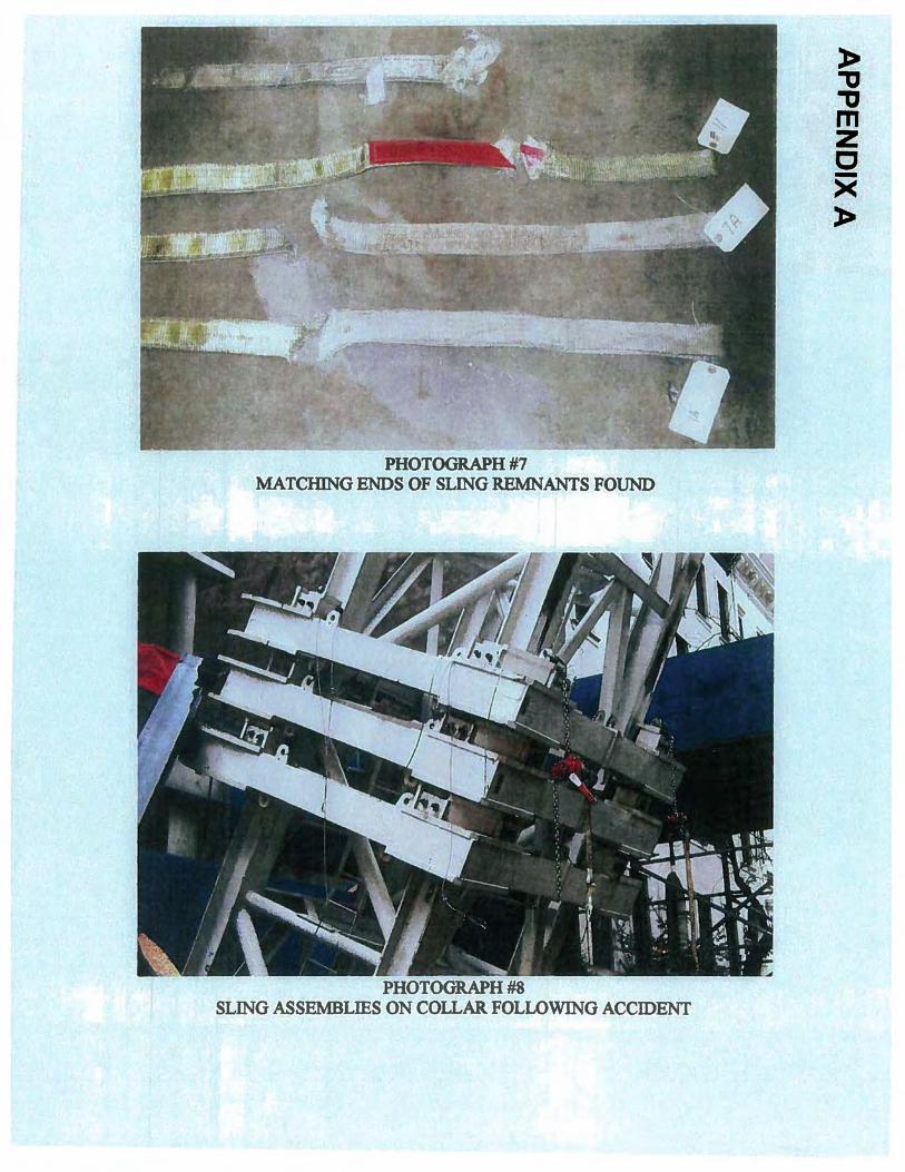
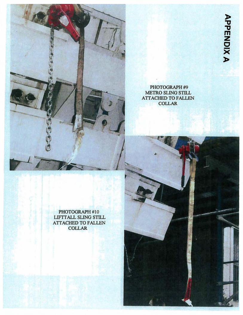
Due to all four web slings breaking, there would have been eight sling remnants remaining. However, only seven sling sections were discovered, with the choked section of the Metro sling missing. The sling remnants were matched with opposing mates, and was accomplished by comparing types, lengths and angular cuts as much as possible (Photograph #7). The photographs from the scene of the accident assisted in positioning the slings on the collars (Photograph #8). Photograph #9 depicts the Metro sling, sample lA, at the southwest comer of the collar, and Photograph #10 shows the southeast comer with sample #11 at the southeast comer. It was determined from segments of the tom identification tag that sample 2A is the companion section of this sling.
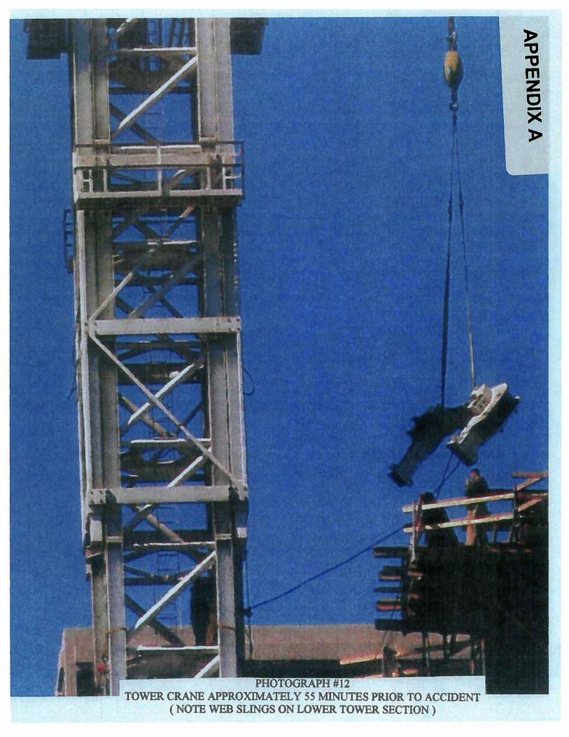
Inspection at the warehouse included inspection of a lower tower crane section along with the steel collar that was attached to the slings which failed. Photograph # 11 shows a section of the crane tower on a flatbed truck. It was originally thought that the slings were choked around the 6" angular struts, but was later discovered following this inspection, that the slings were actually choked around the vertical 12" !-beams. A photograph taken by an individual of the tower crane approximately 55 minutes prior to the accident reveals that the slings ~ere attached to the vertical !-beams (Photograph #12).
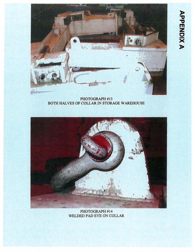
Inspection of the steel collar shows that it is comprised of two sections. A metal tag attached to one of the sections lists a weight of 11,280 #(Photograph #13). Photograph #14 depicts one of the four welded eye pads to which the chain hoist hooks were attached with the use of shackles.
3
APPENDIX A
INSPECTION & TESTING AT SOUTHWEST RESEARCH INSTITuTE
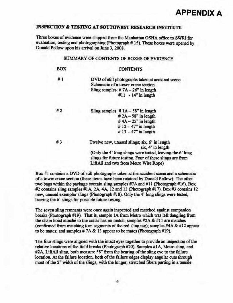
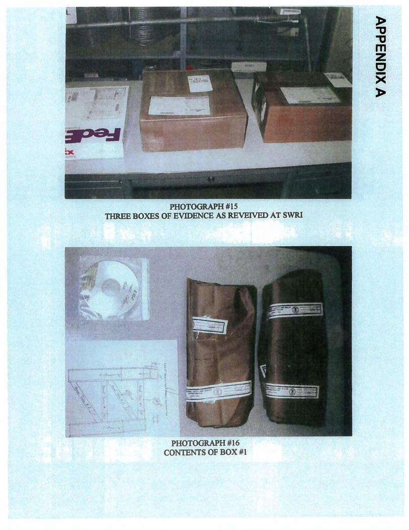
Three boxes of evidence were shipped from the Manhattan OSHA office to ·sWR.I for evaluation, testing and photographing (Photograph# 15). These boxes were o~ed by Donald Pellow upon his arrival on June 3, 2008.
SUMMARY OF CONTENTS OF BOXES OF EVIDENCE
BOX CONTENTS
# 1 DVD of still photographs taken at accident scene Schematic of a tower crane section Sling samples: # 7 A - 26" in length
#11 - 14" in length
# 2 Sling samples: # 1A- 58" in length # 2A- 58" in length # 4A- 25" in le~h # 12 - 4T' in length # 13 - 47'' in length
# 3 Twelve new, unused slings; six, 6' in length six, 4' in length
(Only the 4' long slings were tested, leaving the 6' long slings for future testing. Four of these slings are from LiftAII and two from Metro W~re Rope)
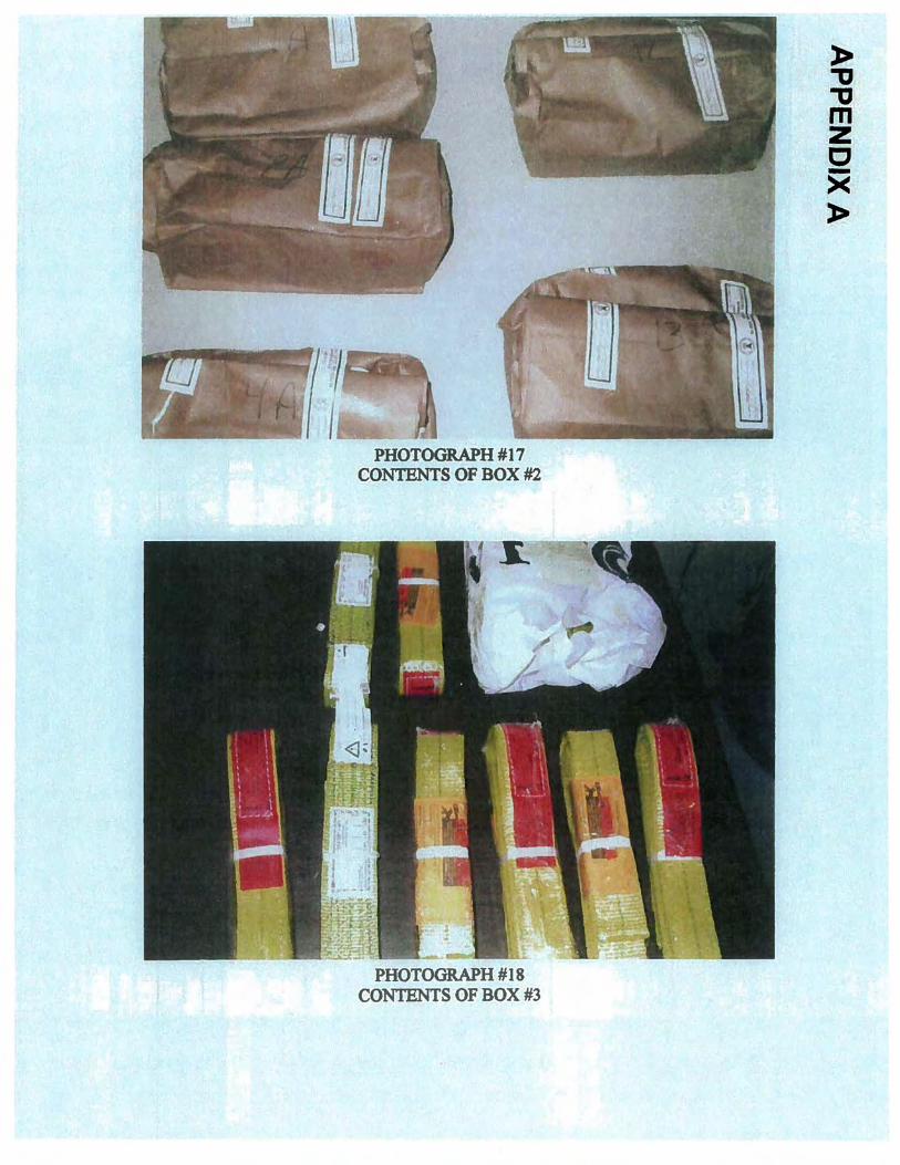
Box #1 contains a DVD of still photographs taken at the accident scene and a schematic of a tower crane section (these items have been retained by Donald Pellow). The other two bags within the package contain sling samples #7 A and #11 (Photograph #16). Box #2 contains sling samples #1A, 2A, 4A, 12 and 13 (Photograph #17). Box #3 contains 12 new, unused exemplar slings (Photograph #18). Only the 4' long slings were tested, leaving the 6' slings for possible future testing.
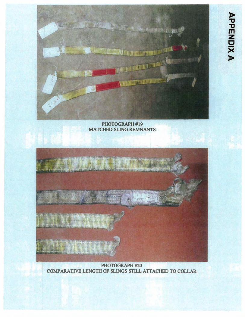
The seven sling remnants were once again inspected and matched against companion breaks (Photograph #19). That is, sample 1A from Metro which was left dangling from the chain hoist attache to the collar has no match; samples #2A & #11 are matches (confirmed from matching tom segments of the red sling tag); samples #4A & #12 appear to be mates; and samples# 7 A & 13 appear to be mates (Photograph #19).
The four slings were aligned with the intact eyes together to provide an inspection of the relative locations of the field breaks (Photograph #20). Samples #1A, Metro sling, and #2A, LiftAII sling, both measure 58" from the bearing of the sling eye to the failure location. At the failure location, both of the failure edges display angular cuts through most of the 2" width of the slings, with the longer, stretched fibers parting in a tensile
4
APPENDIX A
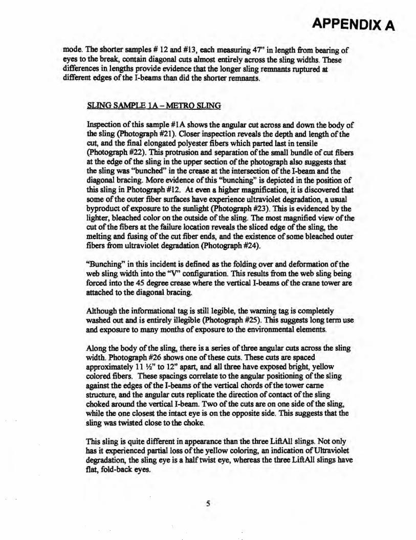
mode. The shorter samples# 12 and #13, each measuring 47" in length from bearing of eyes to the break, contain diagonal cuts almost entirely across the sling widths. These differences in lengths provide evidence that the longer sling remnants ruptured at different edges of the 1-beams than did the shorter remnants.
SLING SAMPLE 1A- METRO SLING
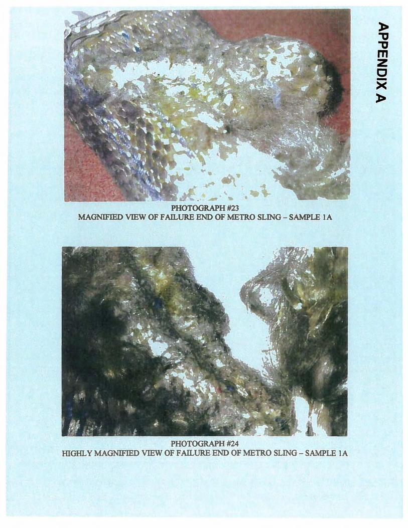
Inspection of this sample # lA shows the angular cut across and down the body of the sling (Photograph #21 ). Closer inspection reveals the depth and length of the cut, and the final elongated polyester fibers which parted last in tensile (Photograph #22). This protrusion and separation of the small bundle of cut fibers at the edge of the sling in the upper section of the photograph also suggests that the sling was "bunched" in the crease at the intersection of the 1-beam and the diagonal bracing. More evidence of this "bunching" is depicted in the position of this sling in Photograph #12. At even a higher magnification, it is discovered that some of the outer fiber surfaces have experience ultraviolet degradation, a usual byproduct of exposure to the sunlight (Photograph #23). This is evidenced by the lighter, bleached color on the outside of the sling. The most magnified view of the cut of the fibers at the failure location reveals the sliced edge of the sling, the melting and fusing of the cut fiber ends, and the existence of some bleached outer fibers from ultraviolet degradation (Photograph #24).
"Bunching" in this incident is defined as the folding over and deformation of the web sling width into the "V" configuration. This results from the web sling being forced into the 45 degree crease where the vertical !-beams of the crane tower are attached to the diagonal bracing.
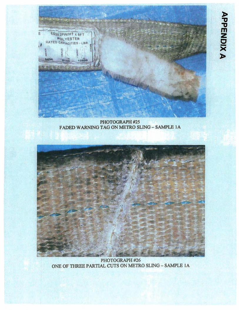
Although the informational tag is still legible, the warning tag is completely washed out and is entirely illegible (Photograph #25). This suggests long term use and exposure to many months of exposure to the environmental elements.
Along the body of the sling, there is a series of three angular cuts across the sling width. Photograph #26 shows one of these cuts. These cuts are spaced approximately 11 W' to 12" apart, and all three have exposed bright, yellow colored fibers. These spacings correlate to the angular positioning of the sling against the edges of the !-beams of the vertical chords of the tower carne structure, and the angular cuts replicate the direction of contact of the sling choked around the vertical 1-beam. Two of the cuts are on one side of the sling, while the one closest the intact eye is on the opposite side. This suggests that the sling was twisted close to the choke.
This sling is quite different in appearance than the three Lift.All slings. Not only has it experienced partial loss of the yellow coloring, an indication ofUltraviolet degradation, the sling eye is a half twist eye, whereas the three Lift.All slings have flat, fold-back eyes.
5
APPENDIX A
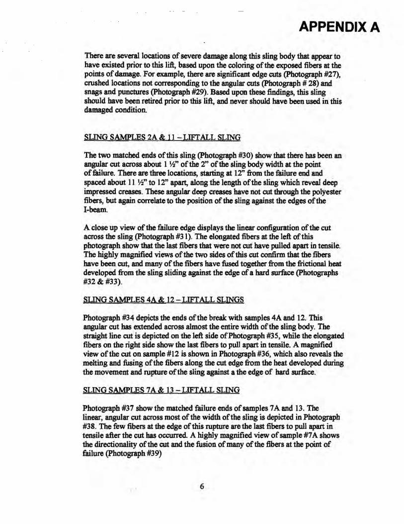
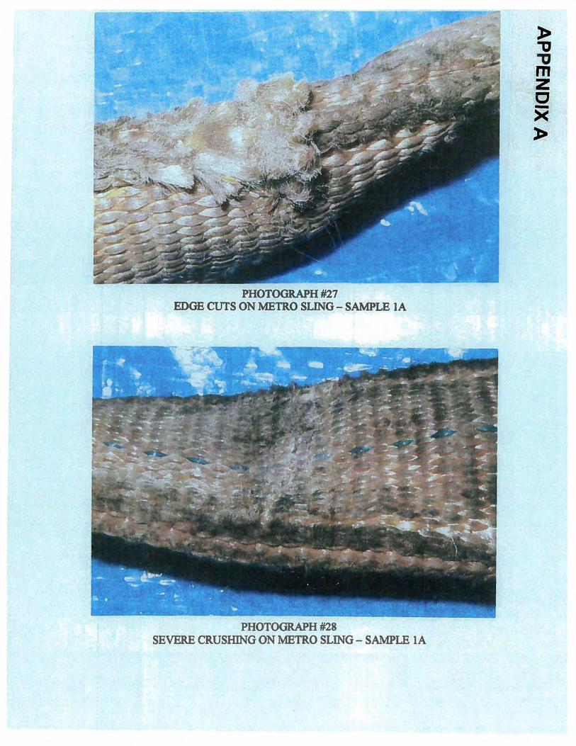
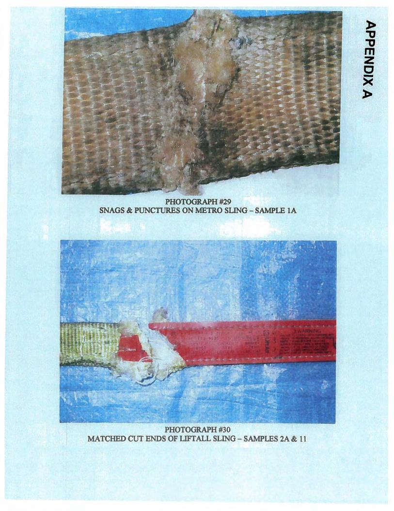
There are several locations of severe damage along this sling body that appear to have existed prior to this lift, based upon the coloring of the exposed fibers at the points of damage. For example, there are significant edge cuts (Photograph #27), crushed locations not corresponding to the angular cuts (Photograph # 28) and snags and punctures (Photograph #29). Based upon these findings, this sling should have been retired prior to this lift, and never should have been used in this damaged condition.
SLING SAMPLES 2A & 11 -LIFT ALL SLING
The two matched ends of this sling (Photograph #30) show that there has been an angular cut across about 1 ~"of the 2" of the sling body width at the point of failure. There are three locations, starting at 12" from the failure end and spaced about 11 W' to 12" apart, along the length ofthe sling which reveal deep impressed creases. These angular deep creases have not cut through the polyester fibers, but again correlate to the position of the sling against the edges of the 1-beam.
A close up view of the failure edge displays the linear configuration of the cut across the sling (Photograph #31). The elongated fibers at the left of this photograph show that the last fibers that were not cut have pulled apart in tensile. The highly magnified views of the two sides of this cut confirm that the fibers have been cut, and many of the fibers have fused together from the frictional heat developed from the sling sliding against the edge of a hard surface (Photographs #32!).
SLING SAMPLES 4A & 12- LIFT ALL SLINGS
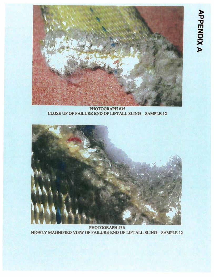
Photograph #34 depicts the ends of the break with samples 4A and 12. This angular cut bas extended across almost the entire width of the sling body. The straight line cut is depicted on the left side of Photograph #35, while the elongated fibers on the right side show the last fibers to pull apart in tensile. A magnified view of the cut on sample #12 is shown in Photograph #36, which also reveals the melting and fusing of the fibers along the cut edge from the heat developed during
· the movement and rupture of the sling against a the edge of hard surface.
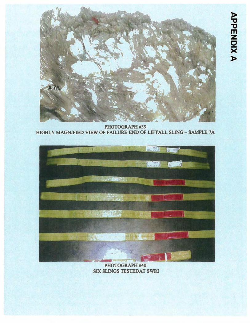
SLING SAMPLES 7A& 13 -LIFTALL SLING
Photograph #37 show the matched failure ends of samples 7 A and 13. The linear, angular cut across most of the width of the sling is depicted in Photograph #38. The few fibers at the edge of this rupture are the last fibers to pull apart in tensile after the cut has occurred. A highly magnified view of sample #7 A shows the directionality of the cut and the fusion of many of the fibers at the point of failure (Photograph #39)
6

APPENDIX A
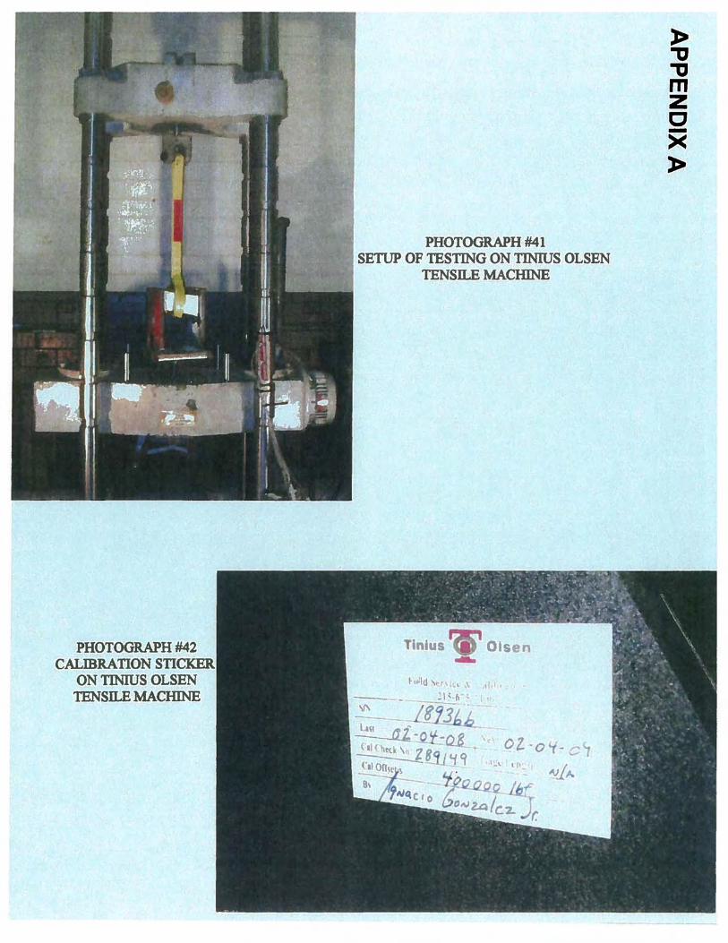
TESTING OF EXEMPLAR SLINGS AT SWRI
The six slings tested are shown.in Photograph #40. Four of these slings are from Lift:All and two are from Metro Wire Rope. However, the sling tags containing the lifting capacities are similar to the tag on the Metro sling which ruptured on the tower crane. The ultimate strength tests were conducted at SWRI on a 400,000 # Tinius Olsen tensile testing machine. The configuration of testing consists of placing one eye of a sling around a 1 %" diameter pin at the top dead end, and choking the other end around the live end (Photograph #41 ). This machine was last calibrated on February 4, 2008 by the Tinius Olsen Company (photograph #42).
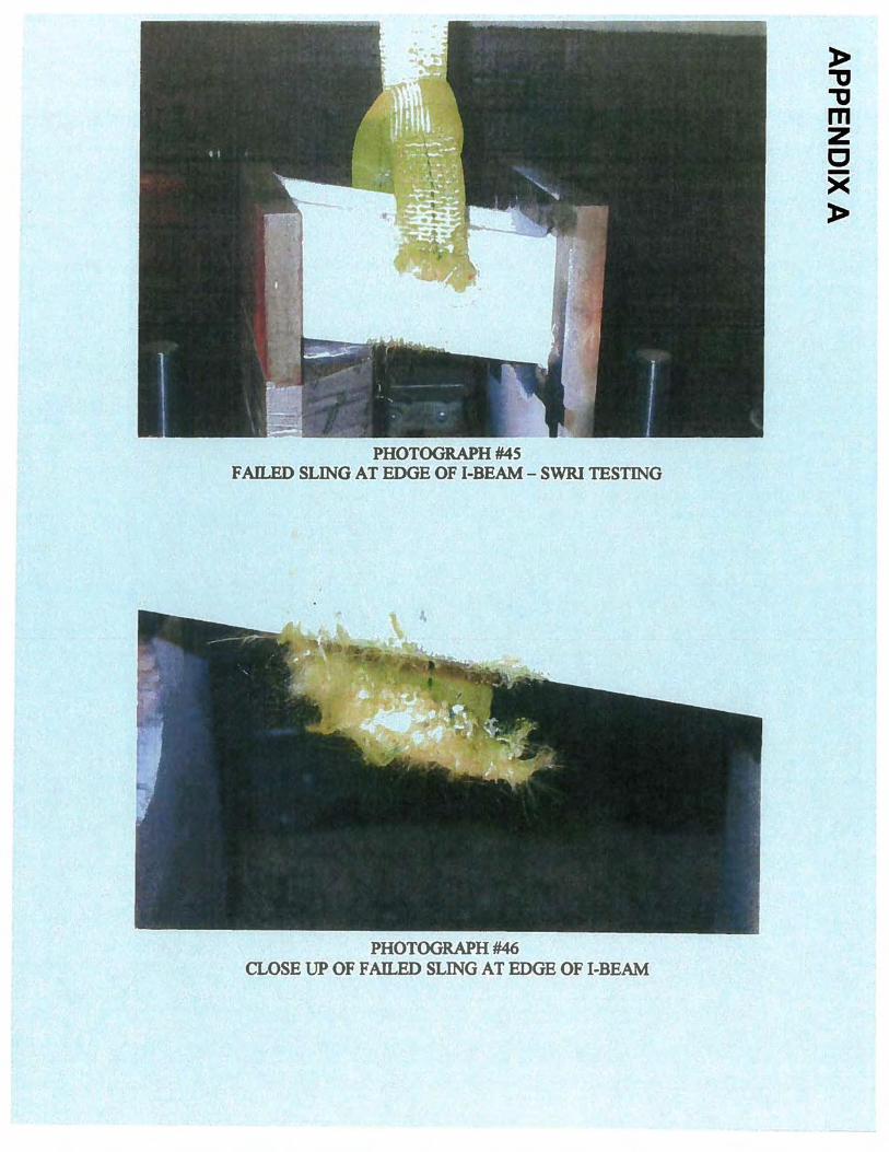
When testing was initially planned at SWRI, the information provided stated that the slings were choked round the 6' angular struts of the crane. Therefore, SWRI set up testing to replicate this condition. Two working days prior to testing, it was discovered that the slings had actually been choke around the 12" vertical 1-beam chords of the tower crane, and not the 6' horizontal struts. SWRI was able to expedite fabrication of a new test frame using an I -beam so testing could continue on the imposed, limited time schedule to complete this phase of testing. However, this test frame was unable to accommodate a 12" 1-beam. Therefore, a section of a 4" 1-beam, which is the largest that could be accommodated in the test frame, was welded to the two plates, at about a 13 degree angle. This angle is the largest that could be used in this testing equipment without side loading and possible fracturing the testing pin on the bottom of the frame. Therefore, these tests reflect the loading of the sling against similar edges of an 1-beam, but at a small diagonal angle than was experienced on the tower crane. Testing at a larger horizontal angle, as was experienced on the crane at the time of the accident, provides more sliding of the slings against the steel edges and more "bunching'' of the slings in the "V'' area where the vertical !-beams of the crane tower are attached to diagonal bracing. This was accomplished at Lehigh University.
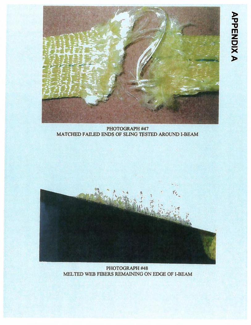
The first series of SWRI tests positions the lower sling eye choked around the angular 1-beam (Photograph #43). The edges of the 1-beam closely duplicate the edges of the 1-beam chords of the tower crane, and the angle will induce some limited movement of the sling along the 1-beam during testing (Photograph #44). The first test, involving a Lift:All sling, broke at 15,275 #at the lower edge of the beam closest to the choked eye (Photograph #45). A close up view of the break shows the cutting of the sling along the edge of the beam, and reveals that the fibers have fused along this cut from movement of the sling against the edge of the 1-beam (Photograph #46). After removal of the sling from the test frame, the side view of the sling break reveals that the break occurred at the angle of the beam in relation to the sling body and that the cut fibers extend across most of the sling body width (photograph # 47).
Inspection of the edge of the 1-beam where the web sling broke reveals that the polyester fibers of the sling have been cut and melted on the edge of the beam (Photograph #48). There is also evidence of slight slippage of the sling at the edge of the beam. A larger included angle of the beam with the sling would be expected to produce more slippage and a lower breaking strength.
7

APPENDIX A
The second sling tested was from Metro Wire Rope. The same type of break occurred at the same location at a force of 16,291 #.
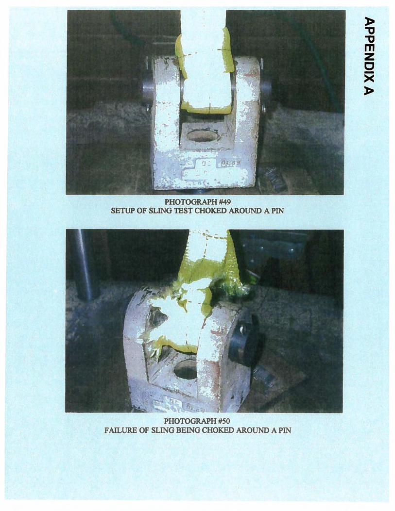
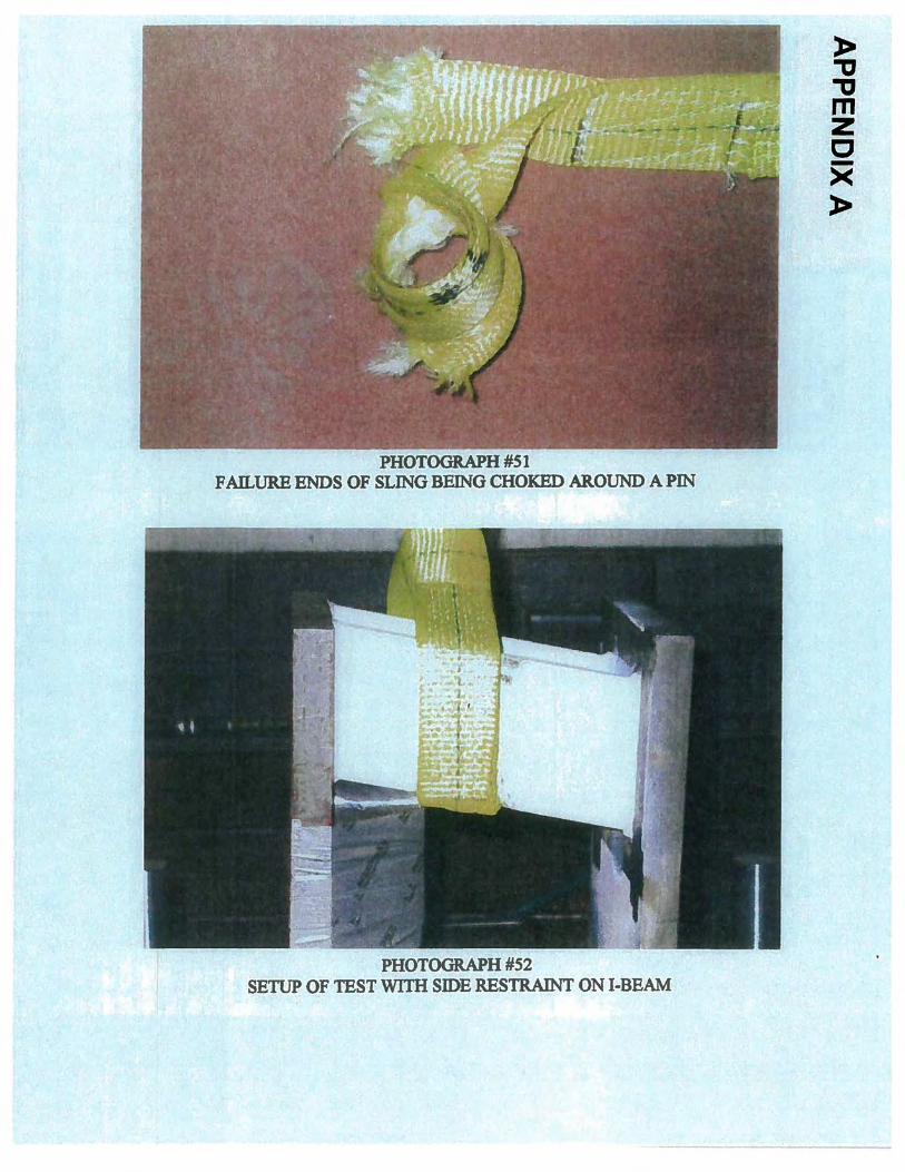
The second series of tests consists of choking the lower eyes around a 1 %" diameter pin (Photograph #49). As expected, the slings failed at the choked location on the pin. The LiftAll sling broke at 21,410 # and the unidentified sling broke at 20, 102 # (Photograph #50). After removal from the pin, the sling break show that the fibers have parted in a tensile and shearing (Photograph #51) and there is no sign of cut fibers.
The fifth test involves placing a side restraint against the side of the sling as it is choked around the I-Beam (Photograph #52). It was the intent to possibly introduce a sideward shearing force and bunching, but this small angle resulted in only preventing the sling from sliding along the 1-beam. This test sample broke at 16,576 #.
The last test involves testing a sling with both eyes around 1 %"pins. This is expected to produce the highest breaking strength of all tests. The sling began parting at 32,767 # with all fibers elo~ing and pulling apart in a tensile mode (Photograph #53). There is no cutting, and the elongation and stretching of the fibers are identical in appearance to the last fibers in the incident slings which pulled apart in tensile after cutting occurred.
SUMMARY OF TEST DATA & OPINIONS
SLING SAMPLE RIGGING BREAKING STRENGTH LOCATION OF BREAK
Lift All Choke around I-Beam
Metro Wire Rope " LiftAII Choke around
1 %"Pin Metro Wire Rope " LiftAII Choke around
1-Beam LiftAII Eye & Eye with
Both Ends Around 1 %"Pins
15,275 #
16,291 # 21,410 #
20,102# 16,576 #
32,767 #
Leading Edge ofi-Beam
Lead;ng Edge ofi-Beam At Choke of Eye
At Choke ofEye Leading Edge ofi-Beam
In Body of Sling
These tests could not fully model the sling configuration that was present at the time of the incident. However, this data does confirm that a significant loss in web sling strength is experienced. when pulling against the edge of an 1-beam. Only slight "bunching" and sliding of the web slings did occur during these tests; however, more severe "bunching" and sliding of the slings on the tower of the crane will produce much more loss in strength. Additional testing at Lehigh University, as described later, confirms this expectation of greater loss with a more severe angle of loading.
8
APPENDIX A
From these tests, it is apparent that the cutting edge of the 1-Beam at.l3 degrees. will reduce the strength of a new, unused sling by 500/o. However, it is expected that pulling downward on a sling choked around a vertical 1-Beam at approximately 45 degrees with the diagonal bracing will result in more slippage of the sling and more severe cutting. This will result in a breaking strength significantly lower than the approximate 16,000 #
. obtained in these tests. That is, at a greater sling angle with the diagonal bracing, as was experienced on the crane tower, the more severe "bunching" will further reduce the sling strength by unbalancing the loading across the sling width.
This greater angle of 45 degrees will also promote more sling slippage of the slings against the edges of the 1-beams during loading, resulting in a dynamic cutting action on the sling and instantaneous frictional heat, both of which reduce the strength of web slings. The Lehigh University tests, along with accident investigations involving failures of web slings, verify.that these factors ofloading a web sling against a hard, unyielding edge, along with movement of the sling and frictional heat, do result in significant strength loss. In addition, "bunching", or folding of the sling in the crease between the vertical 1-beam and the edge of a diagonal brace, will further reduce the strength of the sling.
The Metro sling, which appears to have broken first, was in a damaged condition prior to this lift and was in a weakened condition. So with the additional damaging factors as previously described, plus the fact that the sling was twisted at least once, the Metro sling was most likely being loaded very close to its remaining breaking strength just prior to it rupturing. At this critical moment, any slight movement or shock loading within the lifting system could cause the Metro sling to part.
It is reported that the collar was being manipulated by use a crowbar and a workman was working on top of the collar. These dynamics could likely have caused the Metro sling to fmally part. When the Metro sling did faiL the collar tilted, placing most, if not alL of the load on the two adjacent slings. This does not account for the additional dynamic loading on these slings resulting from the shock or impact loading from the falling edge of the collar. The tilting of the collar would also produce movement in the system and possible sliding of the slings against the 1-beams and diagonal bracing.
Once the Metro sling parted, the evidence suggests that the southeast Lift:All sling (samples 2A & 11) then failed in an identical manner that the Metro sling broke; i.e., in the "V" crease where severe "bunching" has developed. Once these two slings had failed, the last two slings on the north side received an additional loading from shock and cutting action which caused them to cut and fail along an edge of the vertical I -beams.
TESTING AT LEHIGH UNIVERSITY
Final testing was conducted in the Fritz Laboratory at Lehigh University on August 19, 2008. These tests were conducted on an actual section of the crane tower involved in the accident. New, unused, 6' long, polyester web slings were obtained from Metro Wtre
9
APPENDIX A
Rope and LiftAll, manufacturers of the slings involved in the accident. From photographs taken just prior to the accident, it was possible to discern the position of the web slings on the tower and to duplicate these loading conditions in the laboratory.
A series of breaking strength tests on several slings was conducted. These all involved the web slings being choked around the vertical !-beams of the tower section in a like manner as seen in Photograph # 12.
All test results, data and loading graphs are available in the Lehigh University report. All of the slings broke at very low values in the "V" crease where the vertical !-beams connect to the diagonal bracing. This is the location where severe "bunching", cutting and sliding of the slings occurs. The configuration of the breaks and location of partial diagonal cuts are identical to those found on the Metro Wire Rope sling (SW comer) and the LiftAll sling (SE comer) involved in the accident. As expected, all slings broke at very low values, nearing the rated capacities of new, unused slings.
In all tests, as the slings were being subjected to increasing loads, the slings would abruptly slip and adjust through the choke. These adjusting movements began at about 2500# and continued at various load levels up to breaking strength. Audible tearing of the web filaments began at approximately 5500# and continued until final breaking strength.
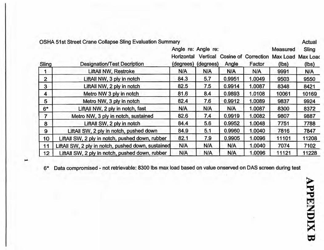
When pulled to ultimate strength, the forces required to break the slings in the "V'' crease were consistent. With the additional third ply of material in the location of the choke, both the Metro Wire Rope and the Lift.All slings broke in the range of 9550 #to 10, 169#. With only two plies of webbing in the "V'' crease, the breaking strengths range from 7788# to 8421#. This slight decrease was expected due to the extra ply of webbing in the cutting area. Placement of rubber pads in the "V" crease and on the edges of the beam provided only a small amount of protection, as the breaking strength reached only about 11,000#.
The result that is remarkable is test sling #11. This sling was loaded to about 7000#, slightly above where web fibers began to fail in the "V" crease. This load was sustained for a period of time during which webbing fibers continued to fail. The sling eventually failed at this load of approximately 7000#, which shows a delayed, prolonged failure.
SUMMARY
A The investigation of the failed slings, along with the tests conducted at SWRI and Lehigh University, indicate that one of the factors that led to the failures of the four slings is cutting of the sling webbing against the edges of the vertical !-beam chords of the tower crane at an angular direction.
B. The test results at Lehigh· University indicate that the Metro Wire Rope web sling in the SW comer and the Lift.All web sling in the SE comer failed in the "V'' crease of the tower section where the vertical !-beams are attached to the diagonal bracing. This "bunching" is another factor in causing the sling to fail by further
APPENDIX A
decreasing the strength of the slings and promoting additional cutting against the diagonal bracing.
C. A third awse of the slings failing was the use of a deteriorated web sling that showed conditions of retirement prior to the lift. The Metro Wire Rope web sling (SW comer) was in a highly worn and used condition prior to this accident. It is believed that this was the first sling to fail. Because of an identical mode and location of break, it is believed that the second sling to fail was the LiftAll sling on the SE comer. The last two slings to break appear to be the LiftAll slings on the NE and NW comers. These two slings o the north side broke at the edges of the vertical I-beams from being cut under a shock loading.
D. The Metro web sling in the SW comer appears to have been used for a much longer period of time than the three LiftAll slings. Prior to being used in this lift, the Metro sling appears to have lost a considerable amount of strength from ultraviolet degradation, edge cuts, snags, punctures and crushing. The fact that the edges of the I-beam cut through the sling fibers at all contacts points of this sling, as opposed to only crushing the other three slings at the contact points (aside from the failure of the two slings on the north side), is further evidence of the weakened condition of the Metro sling.
E. The inspection criteria used for synthetic web slings is listed in the ASME B 30.9 -Slings safety standard and in the OSHA regulation 29 CFR 1910.184 regarding slings. Directions on inspections and warnings against using damaged slings are provided in ASME B 30.9, OSHA Regulation 29 CFR 1910.184 and on the LiftAll warning tags attached to the slings. If these standards, regulations and industry warnings on inspection had been followed, this sling would never have been used. In addition, if these standards, regulations and warnings on use of synthetic web slings had been followed, this rigging procedure would never have been done.
F. The choking of the web slings around the vertical I-beams was inappropriate and dangerous. This rigging promotes downward sliding of the slings and abrasion and cutting of the slings against the edges of the I -beam. The 90 degree tum from the normal and expected pulling direction also decreases the sling strength. There should have been a reduced loading capacity determined by the riggers when using a choke angle less than the normal expected ~mum of 120 degrees, as noted in ASME B 30.9.
G. The choking of slings around the vertical I-beam also placed a shearing and cutting action on the sling during downward loading from the resulting angular positioning of the slings against the I-beam edges. From the downward pulling of the sling at the choked location the slings will reposition themselves at an angle around the I-beam, as depicted in Photograph #12. This action places more pressure on one edge or'the sling and will cause slings to filii in shearing and cutting at greatly reduced values as compared to the same loading conditions without this angular loading.
H. Appropriate comer protectors or other proven sling protection system should have been used to prevent cutting, abrasion or other damage to the sling. ASME B 30.9, OSHA Regulation 29 CFR 1910.184 and the LiftAll sling warning tag all state that slings shall be padded to protect siing from being damaged or cut from
11

APPENDIX A
edges of the load. No padding or protection was provided to the slings to prevent the cutting which occurred. The Lehigh University tests show that a soft rubber cushion is insufficient to protect web slings from being cut when positioned as they were at the time of the accident.
ROOT CAUSES OF WEB SLING FAILURES
A Use of the highly worn and weakened Metro sling from previous wear and damage. If properly inspected according to ASME safety standard on slings, government OSHA regulation 29 CFR 1910.184 and sling manufacturers warnings, this sling would not have been used.
B. Choking the slings around vertical 1-beam chords of the tower crane structure which induced sliding of the slings along the 1-beam edges; shearing and cutting of the sling at reduced strength levels; and reduced sling capacity due to decreasing the choker angle below the nonnal120 degrees.
C. Placing web slings in the "V" crease of the 1-beams and diagonal bracing subjected the slings to severe "bunching" and reduced strength.
D. Not providing padding or other devices which would prevent cutting and damaging the sling from the edges of the 1-beam.
E. Not providing sling protection which would have prevented "bunching" at the "V" crease at the intersection of the vertical 1-beams and diagonal bracing.
COMMENTS AND DISCUSSION
The SWRI testing provides supportive evidence that the slings were cut and that greatly reduced sling strengths are the result of cutting and abrasion action against hard edges.
The Lehigh University tests provides supportive evidence that "bunching'' of web slings in a "V'' crease results in additional significant strength loss of the slings. The rigging of slings against vertical columns and/or diagonal bracing allows slings to slide along the steel edges, resulting in cutting and frictional heat, both of which reduce sling strength.
Inspection of slings prior to each use is critical in assuring the use of undamaged slings. It is extremely important that a sling be removed from service if any of the retirement criteria is evident.
12
Donald. L. Pellow- P.E. Engineering Consultant
PHOTOGRAPH #I INSPECTION AT NEW YORK OSHA OFFICE
PHOTOGRAPH #2 ONE OF THE FOUR CHAIN HOISTS BEING USED AT TIME OF ACCIDENT
)> "tJ -a m z ~ ->< :a:-
PHOTOGRAPH #3 CHAIN POSITION AFTER BEING PULLED THROUGH HOIST
)> 'lJ 1l m z c ->< >

PHOTOGRAPH #S TAG ON ONE OF LIFT ALL WEB SLINGS
908-~6~69(
DO NO. CEE RATED CAPACITIES
IHT x 6FT POLYE,TER
I RATED r APACmEs- ~B .
PHOTOGRAPH #6 TAG ON THE ONLY METRO WEB SLING
)> "tJ "tJ m z c >< )>
PHOTOGRAPH #7 MATCHING ENDS OF SLING REMNANTS FOUND
PHOTOGRAPH #8 SLING ASSEMBLffiS ON COLLAR FOLLOWING ACCIDENT
> "'0 "'0 m z c >< l>
PHOTOGRAPH #10 LIF'ITALL SLING STnL ATTACHED TO FALLEN
COLLAR
PHOTOGRAPH #9 METRO SLING STILL
ATTACHED TO FALLEN COLLAR

PHOTOGRAPH #11 CRANE SECTION IN STORAGE AT WAREHOUSE
)> ., ., m z c >< )>
TOWER CRANE APPROXIMATELY 55 MINUTES PRIOR TO ACCIDENT (NOTE WEB SLINGS ON LOWER TOWER SECTION)
> -a \J m z c ->< >
PHOTOGRAPH #13 BOTH HALVES OF COLLAR IN STORAGE WAREHOUSE
PHOTOGRAPH #14 WELDED PAD EYE ON COLLAR
)> ., ., m z c )( )>
PHOTOGRAPH #15 THREE BOXES OF EVIDENCE AS REVEIVED AT SWRI
PHOTOGRAPH #16 CONTENTS OF BOX #1
)> ""0 ., m z tJ >< )>
PHOTOGRAPH #17 CONTENTS OF BOX #2
PHOTOGRAPH #18 CONTENTS OF BOX #3
> "'tJ -o m z c ->< )>
PHOTOGRAPH #19 MATCHED SLING REMNANTS
PHOTOGRAPH #20 COMPARATIVE LENGTH OF SLINGS STILL ATTACHED TO COLLAR
)> -o -a m z c >< )>

PHOTOGRAPH #21 FAU..URE END OF METRO SLING- SAMPLE IA
PHOTOGRAPH #22 CLOSE UP OF F.All..URE END OF METRO SLING- SAMPLE IA
~ , "'0 m z c ->< )>
PHOTOGRAPH #23 MAGNIFIED VIEW OFF AlLURE END OF METRO SLING- SAMPLE lA
PHOTOGRAPH #24 IDGHL Y MAGNlFIED VIEW OF FAILURE END OF METRO SLING- SAMPLE IA
l> ., ., m z c >< l>
PHOTOGRAPH #25 FADED WARNING TAG ON METRO SLING- SAMPLE IA
PHOTOGRAPH #26 ONE OF THREE PARTIAL CUTS ON METRO SLING- SAMPLE lA
> "lJ , m z c ->< ~
PHOTOGRAPH #27 EDGE CUTS ON METRO SLING- SAMPLE lA
PHOTOGRAPH #28 SEVERE CRUSHING ON METRO SLING- SAMPLE lA
l> ~ m z c >< >
PHOTOGRAPH #29 SNAGS & PUNCTURES ON METRO SLING- SAMPLE lA
PHOTOGRAPH #30 MATCHED CUT ENDS OF LIFT ALL SLING- SAMPLES 2A & 11
> ., , m z c ->< ~

PHOTOGRAPH #31 CLOSE UP OFF AlLURE END OF LIFT ALL SLING- SAMPLE 2A
PHOTOGRAPH #32 MAGNIFIED VIEW OFF AlLURE END OF LIFT ALL SLING- SAMPLE 2A
> ., ., m z c ->< >

PHOTOGRAPH #33 lllGHL Y MAGNIFIED VIEW FAILURE END OF LIFT ALL SLING- SAMPLE II
PHOTOGRAPH #34 MATCHED F AlLURE ENDS OF LIFT ALL SLING- SAMPLES 4A & 12
)> ., ., m z c >< >
PHOTOGRAPH #35 CLOSE UP OFF All..URE END OF LIFT ALL SLING- SAMPLE 12
PHOTOGRAPH #36 ffiGHL Y MAGNJFIED VIEW OFF All..URE END OF LIFT ALL SLING- SAMPLE 12
)> "'0 "'0 m z c >< )>

7 PHOTOGRAPH #37
MATCHED F AlLURE ENDS OF LIFT ALL SLING- SAMPLES 7 A & 13
H- I ,;;) ' 1'\
PHOTOGRAPH #38 MAGNIFIED VIEW OFF AlLURE END OF LIFT ALL SLING- SAMPLE 13
l> "'0 "'0 m z c >< l>
PHOTOGRAPH #39 InGHL Y MAGNIFIED VIEW OF FAILURE END OF LIFT ALL SLING- SAMPLE 7A
PHOTOGRAPH #40 SIX SLINGS TESTEDAT SWRI
> "tJ ., m z c ->< >
PHOTOGRAPH #42 CALIBRATION STICKER
ON TINIUS OLSEN TENSILE MACHINE
PHOTOGRAPH #41 SETIJP OF TESTING ON TINIUS OLSEN
TENSILE MACHINE
Ol-o't-c... l 'l
)> "tJ "tJ m z c ->< l>

PHOTOGRAPH #44 CHOKED EYE AROUND PIN PRIOR TO TESTING
PHOTOGRAPH #43 LOWER EYE CHOKED AROUND I-BEAM
EYE AROUND 1 %"DIAMETER PIN
)> ., ., m z c >< )>
PHOTOGRAPH #45 FAn..ED SLING AT EDGE OF I-BEAM- SWRI 1ESTING
PHOTOGRAPH #46 CLOSE UP OF FAILED SLING AT EDGE OF I-BEAM
)> \J \J m z c -)(
)>
PHOTOGRAPH #47 MATCHED FAILED ENDS OF SLING 'roSTED AROUND I-BEAM
PHOTOGRAPH #48 MELTED WEB FIBERS REMAINING ON EDGE OF I-BEAM
)> ., ., m z c >< )>
PHOTOGRAPH #49 SETUP OF SLING TEST CHOKED AROUND A PIN
PHOTOGRAPH #50 FAILURE OF SLING BEING CHOKED AROUND A PIN
l> ""0 ""0 m z c ->< )>
PHOTOGRAPH #51 FAILURE ENDS OF SLING BEING CHOKED AROUND A PIN
PHOTOGRAPH #52 SETUP OF TEST WITH SIDE RESTRAINT ON I-BEAM
)> ., ., m z c >< )>

PHOTOGRAPH #53 FIBERS OF WEB SLING F All..ING IN TENSILE TEST
BOTH EYES ON PINS
,. "lJ ., m z c ->< >

APPENDIXB (No. of sheets 2 including this sheet)
--
OSHA 51st Street Crane Collapse Sling Evaluation Summary Actual Angle re: Angle re: Measured Sling
Horizontal Vertical Cosine of Correction Max Load Max Loac
~nng ues1gnat1on! 1 es1 uecnp11on (aegreesJ (aegrees Angle r-ac10r (IDS} \IDSl
1 LiftAII NW Restroke N/A N/A N/A N/A 9991 N/A
2 LiftAII NW, 3 ply in notch 84.3 5.7 0.9951 1.0049 9503 9550
3 LittAU NW, 2 ply in notch 82.5 7.5 0.9914 1.0087 8348 8421
4 Metro NW 3 ply in notch 81.6 8.4 0.9893 1.0108 10061 10169
5 Metro NW, 3 ·ply in notch 82.4 7.6 . 0.9912 1.0089 9837 9924
6* LiftAII NW, 2 ply in notch, fast N/A N/A N/A 1.0087 8300 8372
7 Metro NW, 3 ply in notch, sustained 82.6 7.4 0.9919 1.0082 9807 9887
8 LittAU sw; 2 ply_ in notch 84.4 5.6 0.9952 1.0048 7751 7788
9 LittAU SW 2 ply in notch pushed down 84.9 5.1 0.9960 1.0040 7816 7847
10 LittAU SW 2 ply in notch, pushed down, rubber 82.1 7.9 0.9905 1.0096 11101 11208
11 LittAU SW, 2 ply in notch pushed down sustained N/A N/A N/A 1.0040 7074 7102
12 l.._iftAII SW, 2 ply in notch, pushed down, rubber N/A N/A N/A 1.0096 11121 11228
6* Data compromised - not retrievable: 8300 lbs max load based on value onserved on DAS screen during test
> ~ ~ ~ ~ ~
>< ==