Embed Size (px)
Citation preview
HAL Id: hal-01695338https://hal-mines-paristech.archives-ouvertes.fr/hal-01695338
Submitted on 9 Mar 2018
HAL is a multi-disciplinary open accessarchive for the deposit and dissemination of sci-entific research documents, whether they are pub-lished or not. The documents may come fromteaching and research institutions in France orabroad, or from public or private research centers.
L’archive ouverte pluridisciplinaire HAL, estdestinée au dépôt et à la diffusion de documentsscientifiques de niveau recherche, publiés ou non,émanant des établissements d’enseignement et derecherche français ou étrangers, des laboratoirespublics ou privés.
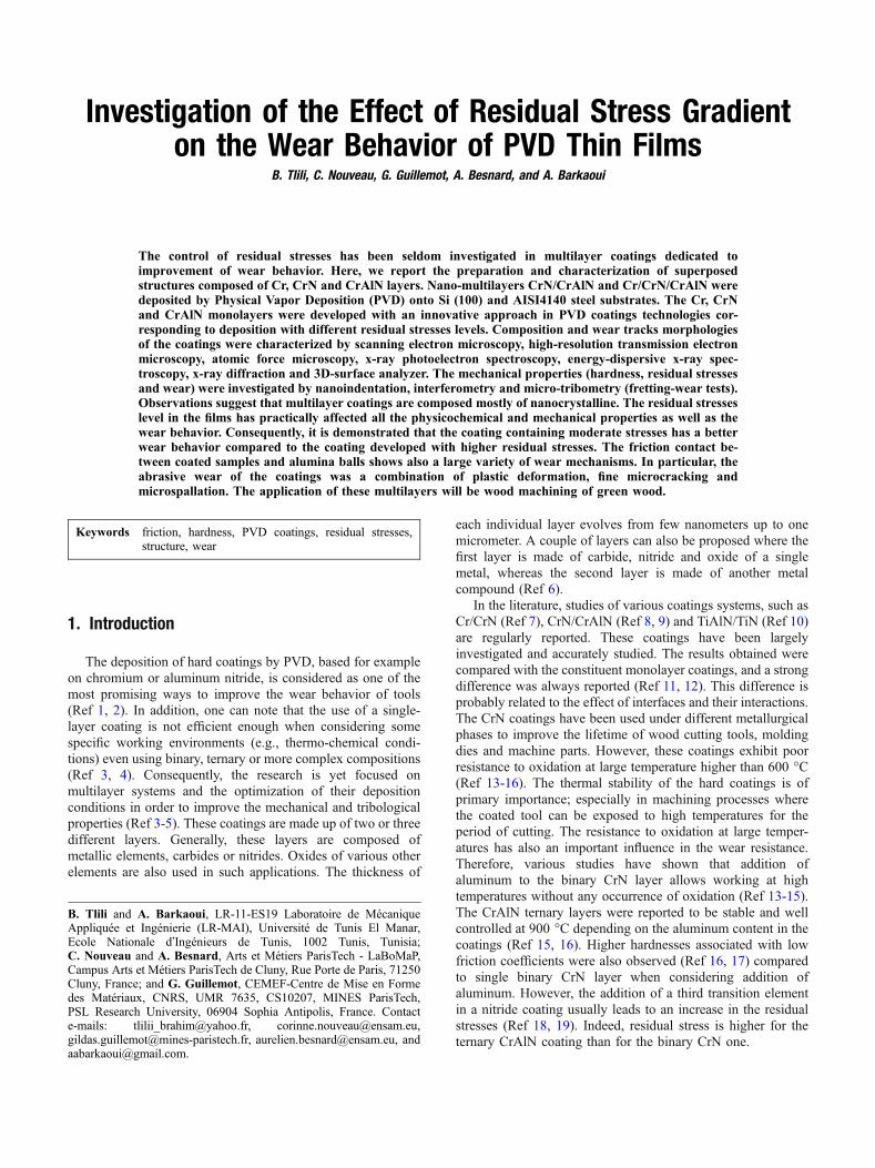
Investigation of the Effect of Residual Stress Gradienton the Wear Behavior of PVD Thin Films
Brahim Tlili, Corinne Nouveau, Gildas Guillemot, Aurélien Besnard, A.Barkaoui
To cite this version:Brahim Tlili, Corinne Nouveau, Gildas Guillemot, Aurélien Besnard, A. Barkaoui. Investigationof the Effect of Residual Stress Gradient on the Wear Behavior of PVD Thin Films. Journal ofMaterials Engineering and Performance, Springer Verlag/ASM International, 2018, 27 (2), pp.457-470. �10.1007/s11665-018-3132-1�. �hal-01695338�
Investigation of the Effect of Residual Stress Gradienton the Wear Behavior of PVD Thin Films
B. Tlili, C. Nouveau, G. Guillemot, A. Besnard, and A. Barkaoui
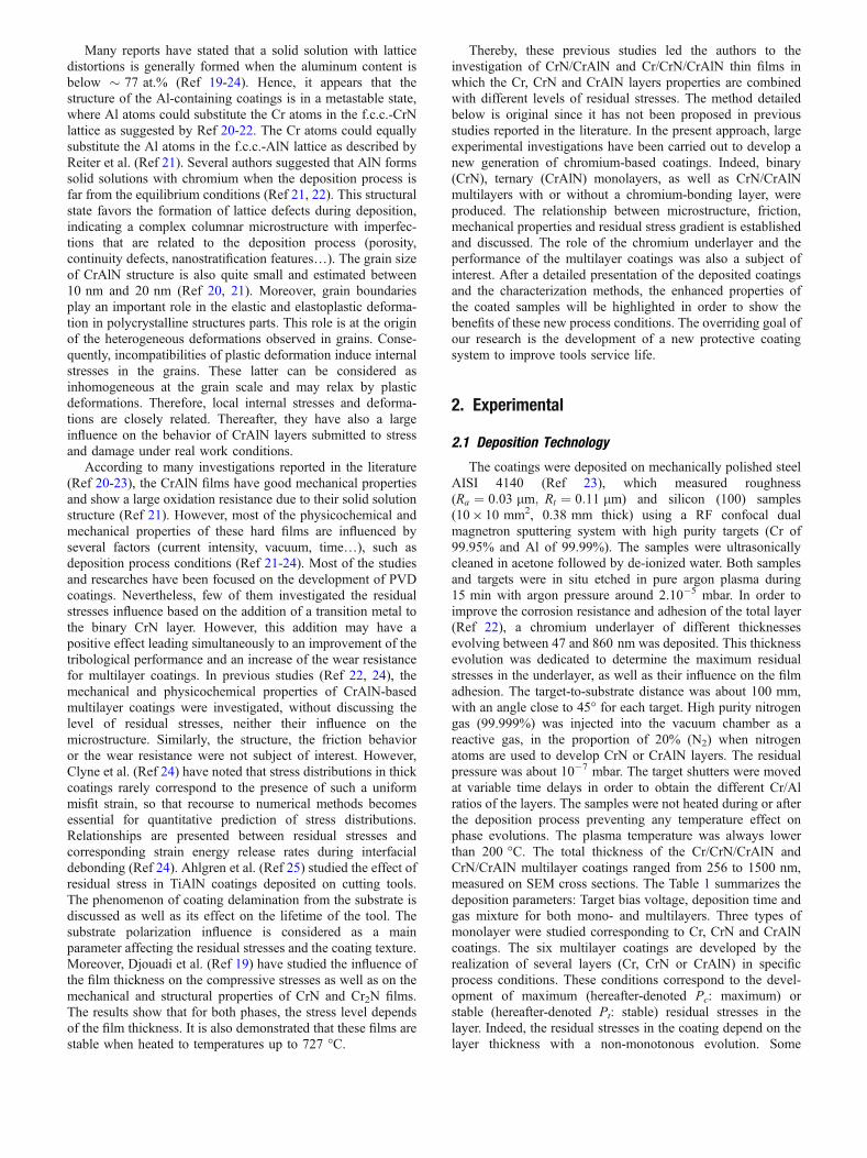
The control of residual stresses has been seldom investigated in multilayer coatings dedicated toimprovement of wear behavior. Here, we report the preparation and characterization of superposedstructures composed of Cr, CrN and CrAlN layers. Nano-multilayers CrN/CrAlN and Cr/CrN/CrAlN weredeposited by Physical Vapor Deposition (PVD) onto Si (100) and AISI4140 steel substrates. The Cr, CrNand CrAlN monolayers were developed with an innovative approach in PVD coatings technologies cor-responding to deposition with different residual stresses levels. Composition and wear tracks morphologiesof the coatings were characterized by scanning electron microscopy, high-resolution transmission electronmicroscopy, atomic force microscopy, x-ray photoelectron spectroscopy, energy-dispersive x-ray spec-troscopy, x-ray diffraction and 3D-surface analyzer. The mechanical properties (hardness, residual stressesand wear) were investigated by nanoindentation, interferometry and micro-tribometry (fretting-wear tests).Observations suggest that multilayer coatings are composed mostly of nanocrystalline. The residual stresseslevel in the films has practically affected all the physicochemical and mechanical properties as well as thewear behavior. Consequently, it is demonstrated that the coating containing moderate stresses has a betterwear behavior compared to the coating developed with higher residual stresses. The friction contact be-tween coated samples and alumina balls shows also a large variety of wear mechanisms. In particular, theabrasive wear of the coatings was a combination of plastic deformation, fine microcracking andmicrospallation. The application of these multilayers will be wood machining of green wood.
Keywords friction, hardness, PVD coatings, residual stresses,structure, wear
1. Introduction
The deposition of hard coatings by PVD, based for exampleon chromium or aluminum nitride, is considered as one of themost promising ways to improve the wear behavior of tools(Ref 1, 2). In addition, one can note that the use of a single-layer coating is not efficient enough when considering somespecific working environments (e.g., thermo-chemical condi-tions) even using binary, ternary or more complex compositions(Ref 3, 4). Consequently, the research is yet focused onmultilayer systems and the optimization of their depositionconditions in order to improve the mechanical and tribologicalproperties (Ref 3-5). These coatings are made up of two or threedifferent layers. Generally, these layers are composed ofmetallic elements, carbides or nitrides. Oxides of various otherelements are also used in such applications. The thickness of
each individual layer evolves from few nanometers up to onemicrometer. A couple of layers can also be proposed where thefirst layer is made of carbide, nitride and oxide of a singlemetal, whereas the second layer is made of another metalcompound (Ref 6).
In the literature, studies of various coatings systems, such asCr/CrN (Ref 7), CrN/CrAlN (Ref 8, 9) and TiAlN/TiN (Ref 10)are regularly reported. These coatings have been largelyinvestigated and accurately studied. The results obtained werecompared with the constituent monolayer coatings, and a strongdifference was always reported (Ref 11, 12). This difference isprobably related to the effect of interfaces and their interactions.The CrN coatings have been used under different metallurgicalphases to improve the lifetime of wood cutting tools, moldingdies and machine parts. However, these coatings exhibit poorresistance to oxidation at large temperature higher than 600 �C(Ref 13-16). The thermal stability of the hard coatings is ofprimary importance; especially in machining processes wherethe coated tool can be exposed to high temperatures for theperiod of cutting. The resistance to oxidation at large temper-atures has also an important influence in the wear resistance.Therefore, various studies have shown that addition ofaluminum to the binary CrN layer allows working at hightemperatures without any occurrence of oxidation (Ref 13-15).The CrAlN ternary layers were reported to be stable and wellcontrolled at 900 �C depending on the aluminum content in thecoatings (Ref 15, 16). Higher hardnesses associated with lowfriction coefficients were also observed (Ref 16, 17) comparedto single binary CrN layer when considering addition ofaluminum. However, the addition of a third transition elementin a nitride coating usually leads to an increase in the residualstresses (Ref 18, 19). Indeed, residual stress is higher for theternary CrAlN coating than for the binary CrN one.
B. Tlili and A. Barkaoui, LR-11-ES19 Laboratoire de MecaniqueAppliquee et Ingenierie (LR-MAI), Universite de Tunis El Manar,Ecole Nationale d�Ingenieurs de Tunis, 1002 Tunis, Tunisia;C. Nouveau and A. Besnard, Arts et Metiers ParisTech - LaBoMaP,Campus Arts et Metiers ParisTech de Cluny, Rue Porte de Paris, 71250Cluny, France; and G. Guillemot, CEMEF-Centre de Mise en Formedes Materiaux, CNRS, UMR 7635, CS10207, MINES ParisTech,PSL Research University, 06904 Sophia Antipolis, France. Contacte-mails: [email protected], [email protected],[email protected], [email protected], [email protected].
Many reports have stated that a solid solution with latticedistortions is generally formed when the aluminum content isbelow � 77 at.% (Ref 19-24). Hence, it appears that thestructure of the Al-containing coatings is in a metastable state,where Al atoms could substitute the Cr atoms in the f.c.c.-CrNlattice as suggested by Ref 20-22. The Cr atoms could equallysubstitute the Al atoms in the f.c.c.-AlN lattice as described byReiter et al. (Ref 21). Several authors suggested that AlN formssolid solutions with chromium when the deposition process isfar from the equilibrium conditions (Ref 21, 22). This structuralstate favors the formation of lattice defects during deposition,indicating a complex columnar microstructure with imperfec-tions that are related to the deposition process (porosity,continuity defects, nanostratification features…). The grain sizeof CrAlN structure is also quite small and estimated between10 nm and 20 nm (Ref 20, 21). Moreover, grain boundariesplay an important role in the elastic and elastoplastic deforma-tion in polycrystalline structures parts. This role is at the originof the heterogeneous deformations observed in grains. Conse-quently, incompatibilities of plastic deformation induce internalstresses in the grains. These latter can be considered asinhomogeneous at the grain scale and may relax by plasticdeformations. Therefore, local internal stresses and deforma-tions are closely related. Thereafter, they have also a largeinfluence on the behavior of CrAlN layers submitted to stressand damage under real work conditions.
According to many investigations reported in the literature(Ref 20-23), the CrAlN films have good mechanical propertiesand show a large oxidation resistance due to their solid solutionstructure (Ref 21). However, most of the physicochemical andmechanical properties of these hard films are influenced byseveral factors (current intensity, vacuum, time…), such asdeposition process conditions (Ref 21-24). Most of the studiesand researches have been focused on the development of PVDcoatings. Nevertheless, few of them investigated the residualstresses influence based on the addition of a transition metal tothe binary CrN layer. However, this addition may have apositive effect leading simultaneously to an improvement of thetribological performance and an increase of the wear resistancefor multilayer coatings. In previous studies (Ref 22, 24), themechanical and physicochemical properties of CrAlN-basedmultilayer coatings were investigated, without discussing thelevel of residual stresses, neither their influence on themicrostructure. Similarly, the structure, the friction behavioror the wear resistance were not subject of interest. However,Clyne et al. (Ref 24) have noted that stress distributions in thickcoatings rarely correspond to the presence of such a uniformmisfit strain, so that recourse to numerical methods becomesessential for quantitative prediction of stress distributions.Relationships are presented between residual stresses andcorresponding strain energy release rates during interfacialdebonding (Ref 24). Ahlgren et al. (Ref 25) studied the effect ofresidual stress in TiAlN coatings deposited on cutting tools.The phenomenon of coating delamination from the substrate isdiscussed as well as its effect on the lifetime of the tool. Thesubstrate polarization influence is considered as a mainparameter affecting the residual stresses and the coating texture.Moreover, Djouadi et al. (Ref 19) have studied the influence ofthe film thickness on the compressive stresses as well as on themechanical and structural properties of CrN and Cr2N films.The results show that for both phases, the stress level dependsof the film thickness. It is also demonstrated that these films arestable when heated to temperatures up to 727 �C.
Thereby, these previous studies led the authors to theinvestigation of CrN/CrAlN and Cr/CrN/CrAlN thin films inwhich the Cr, CrN and CrAlN layers properties are combinedwith different levels of residual stresses. The method detailedbelow is original since it has not been proposed in previousstudies reported in the literature. In the present approach, largeexperimental investigations have been carried out to develop anew generation of chromium-based coatings. Indeed, binary(CrN), ternary (CrAlN) monolayers, as well as CrN/CrAlNmultilayers with or without a chromium-bonding layer, wereproduced. The relationship between microstructure, friction,mechanical properties and residual stress gradient is establishedand discussed. The role of the chromium underlayer and theperformance of the multilayer coatings was also a subject ofinterest. After a detailed presentation of the deposited coatingsand the characterization methods, the enhanced properties ofthe coated samples will be highlighted in order to show thebenefits of these new process conditions. The overriding goal ofour research is the development of a new protective coatingsystem to improve tools service life.
2. Experimental
2.1 Deposition Technology
The coatings were deposited on mechanically polished steelAISI 4140 (Ref 23), which measured roughness(Ra ¼ 0:03 lm; Rt ¼ 0:11 lm) and silicon (100) samples(109 10 mm2, 0.38 mm thick) using a RF confocal dualmagnetron sputtering system with high purity targets (Cr of99.95% and Al of 99.99%). The samples were ultrasonicallycleaned in acetone followed by de-ionized water. Both samplesand targets were in situ etched in pure argon plasma during15 min with argon pressure around 2.10�5 mbar. In order toimprove the corrosion resistance and adhesion of the total layer(Ref 22), a chromium underlayer of different thicknessesevolving between 47 and 860 nm was deposited. This thicknessevolution was dedicated to determine the maximum residualstresses in the underlayer, as well as their influence on the filmadhesion. The target-to-substrate distance was about 100 mm,with an angle close to 45� for each target. High purity nitrogengas (99.999%) was injected into the vacuum chamber as areactive gas, in the proportion of 20% (N2) when nitrogenatoms are used to develop CrN or CrAlN layers. The residualpressure was about 10�7 mbar. The target shutters were movedat variable time delays in order to obtain the different Cr/Alratios of the layers. The samples were not heated during or afterthe deposition process preventing any temperature effect onphase evolutions. The plasma temperature was always lowerthan 200 �C. The total thickness of the Cr/CrN/CrAlN andCrN/CrAlN multilayer coatings ranged from 256 to 1500 nm,measured on SEM cross sections. The Table 1 summarizes thedeposition parameters: Target bias voltage, deposition time andgas mixture for both mono- and multilayers. Three types ofmonolayer were studied corresponding to Cr, CrN and CrAlNcoatings. The six multilayer coatings are developed by therealization of several layers (Cr, CrN or CrAlN) in specificprocess conditions. These conditions correspond to the devel-opment of maximum (hereafter-denoted Pc: maximum) orstable (hereafter-denoted Pt: stable) residual stresses in thelayer. Indeed, the residual stresses in the coating depend on thelayer thickness with a non-monotonous evolution. Some
specific thicknesses hereafter named Pt lead to stable values inresidual stresses. Some other deposited thicknesses lead to asudden variation in same stresses before stabilizing again.These specific thicknesses are hereafter named Pc. The stressesrelated to these thicknesses (Pc and Pt) correspond to specificmonolayer thicknesses used to develop the multilayer coatings.Thicknesses corresponding to both specific residual stresses (Pc
and Pt) have been separately estimated in the preliminarymonolayer experiments before secondary experiments dedi-cated to multilayer coatings. The process parameters leading tothese levels of residual stresses are determined separately, asdetailed hereafter. All the multilayer coatings are rated byPVDi. Properties and characteristics of six specific coatingshave been investigated corresponding to the following combi-nations:
PVD1: (CrN/CrAlN) Pt/Pt
PVD2: (Cr/CrN/CrAlN) Pt/Pt/Pt
PVD3: (CrN/CrAlN) Pc/Pc
PVD4: (Cr/CrN/CrAlN) Pc/Pc/Pc
PVD5: (CrN/CrAlN) Pt/Pc
PVD6: (Cr/CrN/CrAlN) Pt/Pc/Pc
This choice of combination gives the possibility to treat theextreme levels of the residual stresses in all multilayer coatings.Other combinations on these films and related analyses may beachieved in future experiments. However, the associated resultswould be expected in the range of observations detailedhereafter. Our primary focus was only restricted to the analysesof extreme combinations.
2.2 Characterization Methods
The morphological and physicochemical properties as wellas the thin film coating thicknesses have been determined byScanning Electron Microscopy (SEM) and Transmission Elec-tron Microscopy (TEM) observations, followed by energy-dispersive x-ray spectroscopy (JEOL JSM-5900 LV) micro-analyses in the surface. A Siemens D500 x-ray diffractometer(40 kV, 30 mA) has been used to determine the crystal structurewith h–2h scanning mode, using CoKa as the radiation source(k = 0.78 nm). The scanning has been performed at an angleranging from 20 to 120�, for which the angle size and the scoretime at each step were set to 0.05� and 10 s, respectively. Thedetermination of the surface composition is carried out by EDSmicroanalysis. The cross-sectional microstructure was observedby HR-TEM (HF3300 I2TEM). The nanoindentation experi-
ments (nanoindenter type: CSM 2-107) were performed with aBerkovich diamond indenter, and a load ranging from 0.1 to700 mN (load resolution of 50 nN and depth resolution lowerthan 0.01 nm). The hardness measurements were performedinto five points on the same sample surface. Therefore, twenty-five indentation tests by sample were developed in this range ofloads. Several indentation tests have been made for all coatings,and the average value was calculated for more accurate resultswith the associated standard deviation. The load was held at70% of the highest load for 60 s to correct the thermal drift (Ref26). The tip geometry and instrument compliance werecalibrated before any test. The theoretical model developedby Rahmoun (Ref 27) was applied to determine the hardness ofthe films. Surface topography and morphology of the layerwere observed by AFM (Digital Instruments-Santa Barbara-MultiMode SPM Model NanoScope IIIa-CA). AFM wasoperated in tapping mode imaging by acquiring three fieldswith a scan size of 39 3 lm2. The coating composition wascharacterized by XPS using ESCA 3000 (VG Microtech),equipped with a monochromatic aluminum system Ka x-raybeam (energy = 1486.5 eV and 150 W).
In the case of the study of residual stresses, only the internalstress, rt was considered and evaluated (thermal stress andexternal stresses were not considered as their values are lowerthat internal stresses contribution) (Ref 28-34). The Stoneyformula based on the curvature measurement of samples isgenerally used to determine the residual stress value (Ref 33):
ri ¼1
6
Es
1� vs
t2stf
1
R� 1
R0
� �ðEq 1Þ
where Es and vs are the Young�s modulus (130 GPa) andPoisson�s ratio (0.28) of the silicon (100) (Ref 28), ts and tfare the substrate and the film thicknesses, respectively. R0
and R are the substrate curvature radius before and after coat-ing.
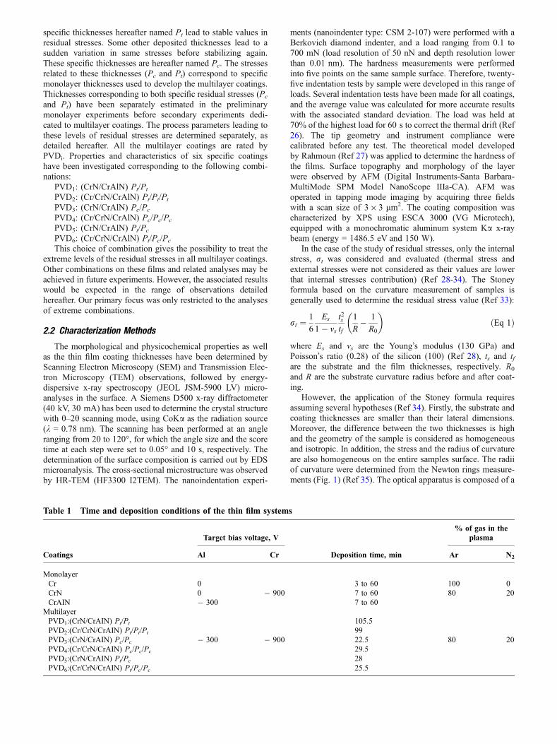
However, the application of the Stoney formula requiresassuming several hypotheses (Ref 34). Firstly, the substrate andcoating thicknesses are smaller than their lateral dimensions.Moreover, the difference between the two thicknesses is highand the geometry of the sample is considered as homogeneousand isotropic. In addition, the stress and the radius of curvatureare also homogeneous on the entire samples surface. The radiiof curvature were determined from the Newton rings measure-ments (Fig. 1) (Ref 35). The optical apparatus is composed of a
Table 1 Time and deposition conditions of the thin film systems
Coatings
Target bias voltage, V
Deposition time, min
% of gas in theplasma
Al Cr Ar N2
MonolayerCr 0 3 to 60 100 0CrN 0 � 900 7 to 60 80 20CrAIN � 300 7 to 60
MultilayerPVD1:(CrN/CrAIN) Pt/Pt 105.5PVD2:(Cr/CrN/CrAIN) Pt/Pt/Pt 99PVD3:(CrN/CrAIN) Pc/Pc � 300 � 900 22.5 80 20PVD4:(Cr/CrN/CrAIN) Pc/Pc/Pc 29.5PVD5:(CrN/CrAIN) Pt/Pc 28PVD6:(Cr/CrN/CrAIN) Pt/Pc/Pc 25.5
sodium vapor source (k = 589.3 nm), a semi-transparent lens, asample holder as well as focusing and projection lenses. Thefollowing relation links the experimental observations devel-oped through this optical device:
d2 ¼ 4Rkm ðEq 2Þ
where d is the diameter of the ring, m is the ring number andR is the curvature radius of the sample. After the analysis ofthe interference rings, the linear relation (Eq 2) is used todetermine this curvature radius. Indeed, the calculation of theslope, a, of the relation between square diameter and associ-ated ring number after experimental observations allows us toestimate this parameter, which is given by the simple rela-tion:
R ¼ a4k
ðEq 3Þ
The radius value is then replaced in the STONEY equation(Eq 1). A tensile stress is obtained when the curvature of thesample is concave, while a compressive stress is consideredwhen this curvature radius is convex. The positive sign isused regarding the international convention for tensile stress.In the opposite case (convex shape), a compressive film stressis obtained corresponding to a negative value. This approachhas been developed on the three monolayer coatings (Cr, CrNand CrAlN) developed on the silicon substrate for variousdeposition times.
Reciprocating wear tests have been performed using amicro-tribometer (Oscillating TRIBO-tester, TRIBO tech-nique), equipped with an alumina ball (Al2O3) with a diameterof 10 mm and a roughness Ra of about 0.52 lm. The tests havebeen conducted under different normal loads (3, 5, 8, 10, and12 N) during 15 min, reciprocated at a frequency of about 2 Hzand with amplitude of 5 mm. The tests have been performed atambient atmosphere (temperature of 22 �C with 31% humidity)
without lubrication. 3D optical profilometer (VEECO-OPTI-CAL 3030) was used to determine the wear track morphology.
3. Results and Discussions
3.1 Monolayer Coatings Study
Cr, CrN and CrAlN monolayer coatings were synthesized bymagnetron sputtering (Table 1). The limiting factors for theapplication of these coatings for protecting cutting tools aretheir lack of adhesion and wear resistance. Consequently, asmentioned previously, it is proposed to superimpose thesecoatings with different level of residual stresses in order todevelop a multilayer coating with enhanced mechanical andtribological properties.
3.1.1 Mechanical Properties. The nanoindentation mea-surements permit to determine the average hardness inmonolayer coating as shown in Fig. 2(a) for a 1-lm-thickCrAlN layer. The Young modulus of coatings could also bemeasured with this approach if required. The hardness values ofeach load cycle are plotted as a function of the penetrationdepth as shown in Fig. 2(b) for the CrAlN coatings. Thisnanohardness-depth profile can be explained by the presence ofthe hard film and its intrinsic properties leading to large value inthe initial depth domain. The mean values of hardness andresidual stresses were determined for all monolayers withdifferent thicknesses based on the Martens hardness analysismethod as proposed by Rahmoun et al. (Ref 27). Figure 3shows that the residual stress deviates directly from the sampleto reach a maximum (Pc) and then stabilizes (Pt) over the rest ofthe film thicknesses for longer deposition times, meaning thatcompressive stress is present and stable. In particular, severalauthors studied the thickness effect on the residual stresses andhave shown that the residual stresses are inhomogeneous
Fig. 1 Newton rings experimental equipment

depending from the layer thickness (Ref 36-38). In our study,the maximum hardness values for the Cr, CrN and CrAlNlayers are, respectively, 16, 28 and 26.5 GPa (accu-racy�± 1GPa) associated with the thickness values of 110,120 and 150 nm. The associated residual stresses are, respec-tively, � 4, � 5.3 and � 3.6 GPa (Fig. 3). It should also benoticed that similar evolutions are observed for residual stressand hardness as a function of the indentation depth. Differenteffects can explain the stress peak (Pc): the creation of defects,the change of crystal orientation or the densification during thelayer growth (Ref 36-48). This peak generally depends on thedeposition conditions and the composition of the layer itself.
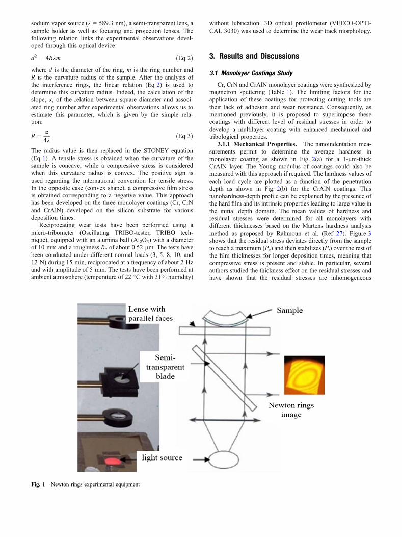
3.1.2 Residual Stresses and Morphology Interac-tion. The AFM observations showed that in the initial stageof film deposition, the development of layer occurs unevenly inan island growth mode. Indeed, Fig. 4 shows this phenomenonas observed in the direction normal to the surface (upper view).An average island stress is smaller than the one encountered ina uniform layer thickness due to the partial stress reduction in aland�s peripheral area. The stress reduction rate is commonlydetermined by the ratio of thickness to size of the islands. Earlyin the formation of the CrAlN layer, the nucleation andprogressive development of many tiny islands are observed onthe substrate corresponding to the initial step before coales-cence mechanism (Fig. 4a). The residual stresses level isconsidered significantly small since these nuclei are tiny andminor. These stresses are attributed to a balance betweensurface stresses and interface stresses, and not only to the
spontaneous generation of residual stresses in the island. Asdeposition time gradually increases, a progressive coalescenceof the tiny nuclei is observed aiming at forming continuousislands (Fig. 4b).
3.2 Multilayers Coatings Study
The superposition of monolayers with different levels ofresidual stresses leads to the development of multilayercoatings (Table 2). The analysis and comparative studybetween the various multilayer coatings systems (PVD1 toPVD6) are based on the nature of layers, the total thickness ofthe film and the residual stress levels in the monolayers.
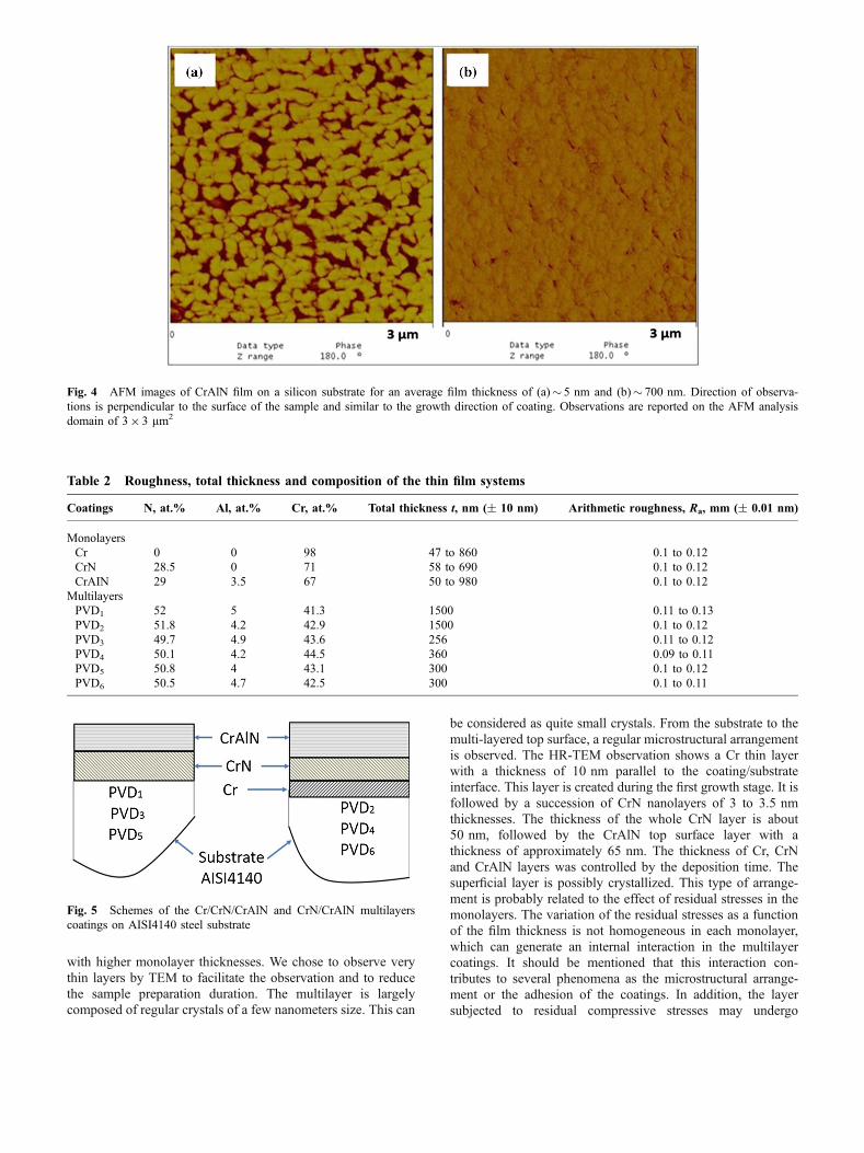
3.2.1 Composition and Structure. The Cr, CrN andCrAlN coatings with different thicknesses were successfullydeposited on a silicon substrate in order to control and optimizethe residual stresses. Through the development of binary andternary layers under optimal conditions, we developed Cr/CrN/CrAlN and CrN/CrAlN multilayer coatings Cr-based (Fig. 5)on AISI 4140 steel substrate. The thickness, roughness andchemical composition of the films are detailed in Table 2. Evenif the SEM observations show a dense multilayer coating, theydo not provide sufficient accurate information on the finemicrostructure. Then, HR-TEM was used to provide additionalobservations. Observations (Fig. 6) have been done on coatingswith specific thicknesses corresponding to minimal residualstresses (Fig. 3) (i.e., the Cr, CrN and CrAlN monolayersthicknesses with, respectively, thicknesses of 10, 50 and65 nm). The PVD2 coating was developed with Pt condition
Fig. 2 Characterization of the CrAlN monolayers (thickness of 1 lm) through five nanoindentation instrumented tests. (a) Loading–unloadingcurves with the load evolution, P, as a function of the indenter displacement, h, (b) Variation of current hardness, H, as a function of the indentdisplacement, h, measured with the indent vibration approach (Frequency 45 Hz, Amplitude of displacement 2 nm)
Fig. 3 Evolution of the hardness (plain lines), H, and residual stresses (dashed lines), rr, as a function of the film thickness, for: (a) Cr, (b)CrN and (c) CrAlN layers deposited on silicon substrate. The magnitudes of compressive residual stresses (negative) are shown in the lower do-main due to their negative values (compressive stresses)
with higher monolayer thicknesses. We chose to observe verythin layers by TEM to facilitate the observation and to reducethe sample preparation duration. The multilayer is largelycomposed of regular crystals of a few nanometers size. This can
be considered as quite small crystals. From the substrate to themulti-layered top surface, a regular microstructural arrangementis observed. The HR-TEM observation shows a Cr thin layerwith a thickness of 10 nm parallel to the coating/substrateinterface. This layer is created during the first growth stage. It isfollowed by a succession of CrN nanolayers of 3 to 3.5 nmthicknesses. The thickness of the whole CrN layer is about50 nm, followed by the CrAlN top surface layer with athickness of approximately 65 nm. The thickness of Cr, CrNand CrAlN layers was controlled by the deposition time. Thesuperficial layer is possibly crystallized. This type of arrange-ment is probably related to the effect of residual stresses in themonolayers. The variation of the residual stresses as a functionof the film thickness is not homogeneous in each monolayer,which can generate an internal interaction in the multilayercoatings. It should be mentioned that this interaction con-tributes to several phenomena as the microstructural arrange-ment or the adhesion of the coatings. In addition, the layersubjected to residual compressive stresses may undergo
Fig. 4 AFM images of CrAlN film on a silicon substrate for an average film thickness of (a)� 5 nm and (b)� 700 nm. Direction of observa-tions is perpendicular to the surface of the sample and similar to the growth direction of coating. Observations are reported on the AFM analysisdomain of 39 3 lm2
Table 2 Roughness, total thickness and composition of the thin film systems
Coatings N, at.% Al, at.% Cr, at.% Total thickness t, nm (± 10 nm) Arithmetic roughness, Ra, mm (± 0.01 nm)
MonolayersCr 0 0 98 47 to 860 0.1 to 0.12CrN 28.5 0 71 58 to 690 0.1 to 0.12CrAIN 29 3.5 67 50 to 980 0.1 to 0.12
MultilayersPVD1 52 5 41.3 1500 0.11 to 0.13PVD2 51.8 4.2 42.9 1500 0.1 to 0.12PVD3 49.7 4.9 43.6 256 0.11 to 0.12PVD4 50.1 4.2 44.5 360 0.09 to 0.11PVD5 50.8 4 43.1 300 0.1 to 0.12PVD6 50.5 4.7 42.5 300 0.1 to 0.11
Fig. 5 Schemes of the Cr/CrN/CrAlN and CrN/CrAlN multilayerscoatings on AISI4140 steel substrate

delamination or some other damages. One can note that theinitial delamination process occurs by crack extension along aplan parallel to the deposition surface. This phenomenongenerally occurs at the film/substrate interface and is describedin our case by the delamination of the chromium underlayerdeposited on the substrate (Fig. 6a). Subsequently, an increasein the coating thickness leads to the disappearance of theordered superimposed monolayers. Indeed the formation of amixed phase (amorphous and crystalline) is observed withspheroidal grains (20 nm of diameter) in the magnification ofthe upper coating domain (Fig. 6b). The behavior is probablyrelated to the relaxation of residual stresses. This phenomenonis also due to the substitution of Cr atoms with the smaller Alones, which results in the contraction of the CrN lattice. Inaddition, this phenomenon can be related to phase separation ofthe hexagonal aluminum nitride h-AlN from the supersaturatedsolid solution of CrAlN. Although the maximum solubility ofAlN in cubic CrN is around 77 mol.% (Ref 48, 49), thesupersaturated CrAlN phase is thermodynamicallymetastable and its stability strongly depends on the depositionconditions. This nanocrystallized phase is attributed to CrN(111) phase while Al is implanted in the amorphous phase.Therefore, small localized and dispersed nanocrystals can beidentified in the rest of the surface after cross-sectionalobservation. It is reasonable to consider that this morphologicalevolution in the multilayer coatings is particularly related tothose internal stresses.
Concerning the structure analysis by XRD, we limited ourstudy to PVD1 and PVD2 patterns due to the thinness of theother films. These thin films are elaborated with moderateresidual stresses (ri < 0.4 GPa). Figure 7 shows the synthe-sized XRD patterns of PVD1 and PVD2 nanoscale multilayers1500 nm thick. Both multilayers were well crystallized in acubic structure. For PVD1 film, the main diffraction peaks (111)and (220) are detected at 43.7� and 76.7�, respectively. This canbe related to the CrN cubic phase structure (JCPS N� 11-0065).The analysis of the PVD2 thin film shows that the CrN (111)diffraction peak has completely disappeared, while the CrN(311) diffraction peak appeared predominantly at 91�, com-
pared to the lower (220) crystalline orientation. This result canbe explained by the higher growth speed of (311) planscompared to (111) plans, or by the preferential sputtering effectof nitrogen atoms on (111) plans (Ref 44).
Qualitative XPS profiles of PVD2 multilayers (deposited onsilicon) elementary composition were established after threeargon etching durations (t1 = 600 s, t2 = 1500 s andt3 = 2520 s). The interlayers/underlayer and underlayer/sub-strate interfaces are not greatly sharp (Fig. 8a). Moreover,Fig. 8(b) shows high-resolution XPS core-level spectra of Crmetal formed by two peaks centered at 574.81 (Cr2p 3/2) and584 eV (Cr2p 1/2). The N1s spectrum (Fig. 8c) reveals thepresence of a nitrogen characteristic peak in cubic chromiumnitride centered at 396.46 eV. Similarly, the Al2p spectrum(Fig. 8d) shows a main peak with a binding energy of 74.3 eVcorresponding to AlN (Ref 44). Furthermore, the Cr3s with Al2pXPS peaks are very similar because the energy level corre-sponding to these two elements are close to each other. Tocomplete this study, we measured the width at half-height onthe same profile spaces of all elements of the PVD1 thin film. Itshould be noticed that the Cr peak becomes more intense when
Fig. 6 HR-TEM cross-sectional images of a Cr/CrN/CrAlN multilayer (respective thicknesses: Cr = 10 nm, CrN = 50 nm and CrAlN = 65 nm)(a) Nanolayers at the substrate/film interface (thickness period of 3 to 3.5 nm), and columnar grains, (b) Dispersion of the crystallites in a par-tially amorphous structure
Fig. 7 XRD patterns of the PVD1, PVD2 multilayers and of theAISI4140 steel substrate
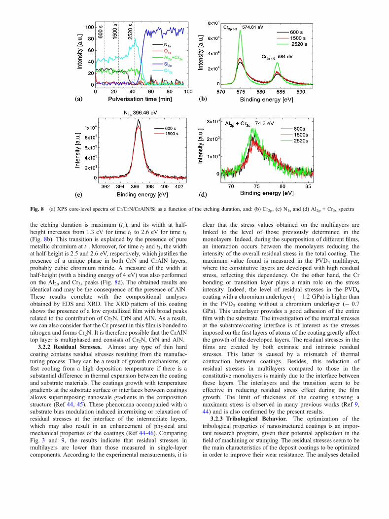
the etching duration is maximum (t3), and its width at half-height increases from 1.3 eV for time t1 to 2.6 eV for time t3(Fig. 8b). This transition is explained by the presence of puremetallic chromium at t1. Moreover, for time t2 and t3, the widthat half-height is 2.5 and 2.6 eV, respectively, which justifies thepresence of a unique phase in both CrN and CrAlN layers,probably cubic chromium nitride. A measure of the width athalf-height (with a binding energy of 4 eV) was also performedon the Al2p and Cr3s peaks (Fig. 8d). The obtained results areidentical and may be the consequence of the presence of AlN.These results correlate with the compositional analysesobtained by EDS and XRD. The XRD pattern of this coatingshows the presence of a low crystallized film with broad peaksrelated to the contribution of Cr2N, CrN and AlN. As a result,we can also consider that the Cr present in this film is bonded tonitrogen and forms Cr2N. It is therefore possible that the CrAlNtop layer is multiphased and consists of Cr2N, CrN and AlN.
3.2.2 Residual Stresses. Almost any type of thin hardcoating contains residual stresses resulting from the manufac-turing process. They can be a result of growth mechanisms, orfast cooling from a high deposition temperature if there is asubstantial difference in thermal expansion between the coatingand substrate materials. The coatings growth with temperaturegradients at the substrate surface or interfaces between coatingsallows superimposing nanoscale gradients in the compositionstructure (Ref 44, 45). These phenomena accompanied with asubstrate bias modulation induced intermixing or relaxation ofresidual stresses at the interface of the intermediate layers,which may also result in an enhancement of physical andmechanical properties of the coatings (Ref 44-46). ComparingFig. 3 and 9, the results indicate that residual stresses inmultilayers are lower than those measured in single-layercomponents. According to the experimental measurements, it is
clear that the stress values obtained on the multilayers arelinked to the level of those previously determined in themonolayers. Indeed, during the superposition of different films,an interaction occurs between the monolayers reducing theintensity of the overall residual stress in the total coating. Themaximum value found is measured in the PVD4 multilayer,where the constitutive layers are developed with high residualstress, reflecting this dependency. On the other hand, the Crbonding or transition layer plays a main role on the stressintensity. Indeed, the level of residual stresses in the PVD4
coating with a chromium underlayer (� 1.2 GPa) is higher thanin the PVD3 coating without a chromium underlayer (� 0.7GPa). This underlayer provides a good adhesion of the entirefilm with the substrate. The investigation of the internal stressesat the substrate/coating interface is of interest as the stressesimposed on the first layers of atoms of the coating greatly affectthe growth of the developed layers. The residual stresses in thefilms are created by both extrinsic and intrinsic residualstresses. This latter is caused by a mismatch of thermalcontraction between coatings. Besides, this reduction ofresidual stresses in multilayers compared to those in theconstitutive monolayers is mainly due to the interface betweenthese layers. The interlayers and the transition seem to beeffective in reducing residual stress effect during the filmgrowth. The limit of thickness of the coating showing amaximum stress is observed in many previous works (Ref 9,44) and is also confirmed by the present results.
3.2.3 Tribological Behavior. The optimization of thetribological properties of nanostructured coatings is an impor-tant research program, given their potential application in thefield of machining or stamping. The residual stresses seem to bethe main characteristics of the deposit coatings to be optimizedin order to improve their wear resistance. The analyses detailed
Fig. 8 (a) XPS core-level spectra of Cr/CrN/CrAlN/Si as a function of the etching duration, and: (b) Cr2p, (c) N1s and (d) Al2p + Cr3s spectra

hereafter are mainly dedicated to the characterization of frictionproperties and wear mechanisms in multilayer coatings depend-ing from their residual stress levels related to the depositconditions.
3.2.3.1 a- Friction Coefficient. The Cr/CrN/CrAlN andCrN/CrAlN multilayer systems are formed by monolayerswhose residual stresses levels are identical (�plate� (Pt) forPVD1 and PVD2 or �peak� (Pc) for PVD3 and PVD4) orcombined (�plate� and �peak� for the PVD5 and PVD6 systems).It should also be pointed out that the total thickness of eachcouples of coatings (i.e., PVD1/PVD2; PVD3/PVD4 and PVD5/PVD6) is of the same order of magnitude or even identical(Table 2). This methodology gives the opportunity to studyproperties of multilayer coatings developed with same phasesbut different level of residual stress leading to various intrinsicproperties. The tribological properties of the as-depositednanocomposite films were determined by reciprocating weartests against an Al2O3 alumina ball under dry wear conditions.Figure 10 shows the evolution of the instantaneous frictioncoefficient (COF) as a function of sliding distance for themultilayers against the alumina ball. Each multilayer showstypical running-in behavior corresponding to an initial transientstage followed by an increase in the COF until a steady state.The initial transient stage corresponds to contact between thehighest asperities of the ball and the coating surface. Vibrationsand noise are also present in the evolutions reported in Fig. 10.
Against alumina, the COF of PVD1 is 0.36 at the beginningof the test in a short running-in period. An increase to 0.65(Fig. 10a) of the COF is observed afterward. The wear becomesmore severe leading to coating failure and to the creation ofdebris which participate to the wear kinetics. Moreover, PVD2
has an initial COF value of 0.28. After a friction distance ofabout 6 m, PVD1 and PVD2 have the same COF value(� 0.57). The shift in the transition period between the twocoatings explains that PVD2 has a better tribological behaviorcompared to PVD1. The PVD3 coating presents a short steadystate period of constant COF of 0.6. The COF of PVD4 starts at0.22 and increases slowly to around 0.5. A small change in thefriction behavior corresponds to the breakdown of the twocoatings after 8 m, and the COF becomes similar, as shown inFig. 10(b). As a result, the superposition of the layers withmaximum residual stresses (PVD3 and PVD4) does not improvethe tribological behavior. The COF shows similar behavior withthe PVD5 coating (Fig. 10c). At the very beginning of thetribological test, a low value of COF property is observed(0.25), but a higher value is quickly reached (0.6) probably due
to high wear and coating�s delamination. A stable domain isobserved after this transient period with a value of � 0.45. Onthe other hand, PVD6 also quickly reaches the high COF valueof 0.6 before a stable domain where a COF value of 0.5 isobserved. This coating contains a Cr bonding underlayer with�plate� stress (Pt) reinforcing its tribological behavior.
As mentioned previously, it is noteworthy that a Transitionzone (Tz) exists for all the multilayers where COF valueevolves quickly. Although the surface layer is always the same,this zone differs from one coating to another with largedifferences. The length of this transient domain can beestimated as follows:
Tz (PVD1)� 3 m<Tz (PVD2)� 4 m (Fig. 10a)Tz (PVD3)� 0.75 m<Tz (PVD4)� 1.2 m (Fig. 10b)Tz (PVD5)� 0.1 m<Tz (PVD6)� 0.4 m (Fig. 10c).This variation is probably related to superficial tribological
transformation (STT). Coatings developed with a bondingunderlayer (Cr) have also a longer Tz domain. Moreover, thisdifference in Tz depends mainly on several factors such as thesurface topography ðRa;RtÞ, the residual stresses in theunderlayer, the adhesion energy at the interface of single-constitutive layers, as well as the adhesion of the coatings withthe substrate (Ref 50). This transition zone corresponds to theoriginal plastic deformation (effect of the friction contact).After this transition period, the coefficient of friction stabilizesat a specific sliding length for each multilayer system. Thevalues obtained are close to 0:58 when the surface layer isproduced with �plate� stresses (Pt) (Fig. 10a), and close to 0:5,when multilayer systems are developed with peak (Pc) orcombined (Pt/Pc) residual stresses (Fig. 10b and c). Conse-quently, similar COF values are obtained on the six differentmultilayer systems. Thereby, residual stresses in the top layer ofthe coating (PVD3-6) have only a slight effect on the COFparameter. However, the accumulation of the plastic deforma-tion in turn causes a shear stress and produces a layer failure.Two consequences of the existence of the transition zone can benoticed:
(1) The exerted shear stress exceeds the adhesion stress andcauses a sudden cracking at the interface and conse-quently the layer spalling.
(2) The shear stress is not sufficient to generate an immedi-ate delamination of the coating. However, when com-bined with the stress at the substrate interface, aninitiation and/or propagation of an interfacial crack oc-curs and grows until a critical size is reached leading toa delamination process.
Consequently, this initial crack causes the initiation ofdamage under the effect of compressive residual stresses in thefilm. The transition period is systematically longer (Tz� 4 mfor PVD2) (Fig. 10a) and more significant in the presence ofhigher residual stresses (rr�� 0.38 GPa for PVD2) (Fig. 9)proving their contribution to the wear resistance and theirimpact to delay the damage at the contact interface. De Wit (Ref51) found in the case of TiN layers that the transition periodcorresponds to the formation of third body « debris » composedof amorphous rutile and nanocrystalline grains. A transforma-tion from the amorphous to the crystalline phase is subse-quently achieved, contributing to further wear. Against aluminaballs, only the PVD2 coating survived to the tribological tests asshown hereafter on Fig. 13 with the negligible value of wearvolume associated to the AISI4140 substrate. The best wear
Fig. 9 Residual stresses of the PVD multilayer coatings with theuncertainties domains

Fig. 10 Friction coefficient vs. the wear track length, d [m], for: (a) PVD1 and PVD2, (b) PVD3 and PVD4, (c) PVD5 and PVD6 (duration offriction test: t = 30 min, Normal force applied: Fn = 5 N, Speed: m = 8 mm s�1 and Amplitude of displacement: d =± 2.5 mm). Left imagesshow the entire observation and right images provide a magnification corresponding to the transition period
Fig. 11 SEM observations developed on the PVD2 thin film corresponding to (a) detached debris from the worn surface and, (b) wear scarmorphologies (duration of the friction test: t = 15 min, normal force applied: Fn = 5 N, speed: v = 8 mm s�1 and amplitude of displacement:d =± 2.5 mm)
behavior was achieved in comparison with the other multilayersystems. Consequently, the PVD2 coating improves the frictionbehavior against Al2O3 balls.
The analysis of wear track after SEM observations revealsthat the debris removed by the friction effect are present at thefirst contact cycles between the antagonists and that the particlesize is lower than 0.5 lm (Fig. 11a). Thereby, some of theparticles are ejected outside the contact zone, whereas theothers remain trapped. Similar results were found in theliterature (Ref 52). The particle forms a third body, whichparticipates to kinematic readjustment of the contact (Fig. 11b).The transition period is reached when the pull-off flow ofparticles becomes steady.
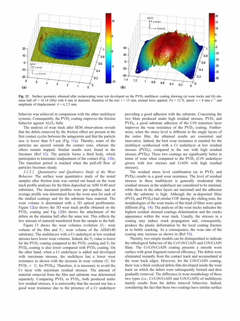
3.2.3.2 Quantitative and Qualitative Study of the WearBehavior. The surface wear quantitative study of the testedsamples after friction tests was carried out based on the weartrack profile analyses for the films deposited on AISI 4140 steelsubstrates. The measured profiles were put together, and anaverage profile was determined from the worn area for each ofthe studied coatings and for the substrate base material. Thewear volume is determined with a 3D optical profilometer.Figure 12(a) shows the 3D wear track profile obtained on thePVD2 coating and Fig. 12(b) shows the attachment of thedebris on the alumina ball after the same test. This reflects thelow amount of material transferred from the sample to the ball.
Figure 13 shows the wear volumes evolution (Vf : wearvolume of the film and Vs: wear volume of the AISI4140substrate). The multilayers with a Cr underlayer at low residualstresses have lower wear volumes. Indeed, the Vf value is lowerfor the PVD2 coating compared to the PVD1 coating and Vf forPVD6 coating is also lower compared with PVD5 coating. Onthe other hand, when a Cr underlayer is added and developedwith maximum stresses, the multilayer has a lower wearresistance as shown with the increase in wear volume (Vf forPVD3< Vf for PVD4). Therefore, it is necessary to avoid theCr layer with maximum residual stresses. The amount ofmaterial removed from the film and substrate was determinedseparately. Comparing PVD1 to PVD2, both produced underlow residual stresses, it is noteworthy that the second one has agood wear resistance due to the presence of a Cr underlayer
providing a good adhesion with the substrate. Concerning thetwo films produced under high residual stresses, PVD3 andPVD4, a good substrate adhesion of the CrN transition layerimproves the wear resistance of the PVD3 coating. Further-more, when the stress level is different in the single layers ofthe entire film, the obtained results are consistent andinnovative. Indeed, the best wear resistance is reached for themultilayer synthesized with a Cr underlayer at low residualstresses (PVD6), compared to the one with high residualstresses (PVD4). These two coatings are significantly better interms of wear when compared to the PVD5 (CrN underlayergrown with low stresses and CrAlN with high residualstresses).
The residual stress level combination (as in PVD5 andPVD6) results in a good wear resistance. The level of residualstresses in these multilayers is generally moderated (theresidual stresses in the underlayer are considered to be minimal,while those in the other layers are maximal) and the adhesionwith the substrate is high. Although the as-deposited films(PVD5 and PVD6) had similar COF during dry sliding tests, themorphologies of the wear tracks of this kind of films were quitedifferent (Fig. 14). The analysis of the wear tracks indicates thehighest residual stressed coatings delamination and the cracksappearance within the wear track. Usually, the stresses in acoating may induce crack propagation and, consequently,produce the plastic deformation by the local coating fractureas in brittle cracking. As a consequence, the wear rate of thecoating may increase as shown in (Ref 53).
Thereby, two simple models can be distinguished to indicatethe tribological behavior of the Cr/CrN/CrAlN and CrN/CrAlNfilms. The Cr/CrN/CrAlN coating presents a smooth wornsurface with great fragment removal efficiency. The debris wereeliminated instantly from the contact track and accumulated atthe wear track edges. However, for the CrN/CrAlN coating,there was a thick oxidized debris film developed inside the weartrack on which the debris were subsequently formed and thengradually removed. The difference in wear morphology of thesetwo types (i.e., Cr/CrN/CrAlN and CrN/CrAlN) of multilayersmainly results from the debris removal behaviors. Indeed,considering the fact that these two coatings have similar surface
Fig. 12 Surface geometry obtained after reciprocating wear test developed on the PVD2 multilayer coating showing (a) wear tracks and (b) alu-mina ball (H = 16.14 GPa) with 6 mm in diameter. Duration of the test: t = 15 min, normal force applied: Fn = 12 N, speed: v = 8 mm s�1 andamplitude of displacement: d =± 2.5 mm

roughness, the wear difference can be attributed to thedifference in the characteristics of debris as well as in thelevel of residual stresses. The results previously detailedindicate that coatings were oxidized during the wear testprobably because of frictional heat (Ref 54). Generally, there isno significant difference in the tribological behavior ofmultilayer coating systems. This behavior is related to the typeof oxides incorporated and formed during friction is similar forall films (Cr2O3, FeO2 and Al2O3) (Ref 55, 56). This shouldlead to the same debris removal behavior between the coatings.It is recognized that the type of multilayers Cr/CrN/CrAlN and
CrN/CrAlN shows the same oxidation resistance; the Al oxidefilms formed during high temperatures are expected to be anefficient thermal barrier as well as a lubricating layer (Ref 55-57). Therefore, it can probably have a crucial role in the wearprocess and slightly affect the tribological behavior. In the lightof these experimental investigations, it is noteworthy that thewear resistance of coatings depends significantly from theirlevel of residual stresses, their tribological properties andchemical composition.
4. Conclusion
Characteristics and properties of Cr, CrN and CrAlNmonolayer coatings deposited by dual RF magnetron sputteringare investigated as a preliminary study. These results lead to thedevelopment of multilayer CrN/CrAlN and Cr/CrN/CrAlN thinfilms with different levels of residual stresses in their constitutivelayers. The physicochemical properties of these coatings aresubsequently investigated. Reciprocating sliding wear tests wereperformed and compared to investigate the tribological proper-ties of the multilayers. Observations and characterizations arefocused on their tribological behavior, wear mechanisms andadhesion properties. The effect on the wear properties andoxidation were also subject of investigation. Several conclusionsare given based on the observations and associated discussions:
1. The multilayers exhibit a prominent reflection along(200) and (111) planes corresponding to the cubic CrNphase,
Fig. 13 Wear volume of the PVDi films (Vf ) and wear volume ofAISI4140 substrate (Vs). Duration of the test: t = 15 min, normalforce applied: Fn = 5 N, speed: v = 8 mm s�1, amplitude of dis-placement: d =± 2.5 mm
Fig. 14 SEM images of the (a) PVD5, (b) PVD6, (c) PVD6. PVDi films worn surfaces sliding against Al2O3 alumina ball and (d) EDS micro-analyses of the debris (duration of the test: t = 15 min, normal force applied: Fn = 5 N, speed: v = 8 mm s�1 and amplitude of displacement:d =± 2.5 mm)

2. The residual stresses in the multilayers are lower thanthose of their single-layer components. This result is re-lated to the physicochemical properties of the layer inter-face and the variation of the partial thickness,
3. The coatings present good adhesion to the substrate,especially the Cr/CrN/CrAlN one. This is due to the pres-ence of the chromium underlayer. This layer reduces thestress extent between the substrate and the main film,
4. Cr/CrN/CrAlN multilayers show a sparsely better frictionproperty and higher wear resistance (in particular PVD2)compared to CrN/CrAlN multilayers developed without aCr underlayer. However, PVD3 and PVD4 thin films pre-pared under high residual stresses suffered severe weareven when moderate normal loads were applied (Fn ‡ 5N). These wear are characterized by a combination ofdelamination, abrasive and oxidative wear,
5. The thin multilayers prepared with low residual stresseslevel are mainly characterized by concentrated wear.Other films, such as PVD6 prepared with combined resid-ual stresses level (lower in Cr, higher in CrN andCrAlN), show considerable improvement in debris re-moval of wear despite a lower thickness and better wearresistance under moderate normal loads.
Acknowledgments
The authors would like to thank Mr. Romain Fliti, Mr. DenisLagadrillere for experimental support, Pr. Alain Iost and Pr. LucImhoff for helpful discussions and collaboration during this work.
References
1. A. Pilkington, S.J. Dowey, J.T. Toton, and E.D. Doyle, Machining withAlCr-Oxinitride Coated Cutting Tools, Tribol. Int., 2013, 65, p 303–313
2. J. Heinrichs, J. Gerth, T. Thersleff, U. Bexell, M. Larsson, and U.Wiklund, Influence of Sliding Speed on Modes of Material Transfer asSteel Slides Against PVD Tool Coatings, Tribol. Int., 2013, 58, p 55–64
3. S. PalDey and S.C. Deevi, Single Layer and Multilayer Wear ResistantCoatings of (Ti, Al) N: A Review, Mater. Sci. Eng. A, 2003, 342(1), p58–79
4. Z. Li, P. Munroe, Z. Jiang, X. Zhao, J. Xu, Z. Zhou, J. Jiang, F. Fang,and Z. Xie, Designing Superhard, Self-Toughening CrAlN CoatingsThrough Grain Boundary Engineering, Acta Mater., 2012, 60(16), p5735–5744
5. M. Cekada, P. Panjan, M. Macek, and P. Amid, Comparison ofStructural and Chemical Properties of Cr-Based Hard Coatings, Surf.Coat. Technol., 2002, 151–152, p 31–35
6. G.S. Kim and S.Y. Lee, Microstructure and Mechanical Properties ofAlCrN Films Deposited by CFUBMS, Surf. Coat. Technol., 2006, 201,p 4361–4366
7. I.M. Penttinen, A.S. Korhonen, E. Harju, M.A. Turkia, O. Forsen, andO. Ristolainen, Comparison of the Corrosion Resistance of TiN and(Ti, Al)N Coatings, Surf. Coat. Technol., 1992, 50, p 161–168
8. M. Vanstappen, B.Malliet, L. De Schepper, L.M. Stals, J.P. Celis, and J.R.Roos, Influence of Ti Intermediate Layer on Properties of Tin CoatingsDeposited on Various Substrates, Surf. Eng., 1989, 5(4), p 305–310
9. G.A. Fontalvo, R. Daniel, and C. Mitterer, Interlayer ThicknessInfluence on the Tribological Response of bi-Layer Coatings, Tribol.Int., 2010, 43, p 108–112
10. C.A. Dobrzanski, M. Polok, P. Panjan, S. Bugliosi, and M. Adaniak,Improvement of Wear Resistance of Hot Work Steels by PVD CoatingsDeposition, J. Mater. Process. Technol., 2004, 155–156, p 1995–2001
11. Y. Birol, Sliding Wear of CrN, AlCrN and AlTiN Coated AISI, H13Hot Work Tool Steels in Aluminum Extrusion, Tribol. Int., 2013, 57, p101–106
12. M. Okumiya and M. Griepentrog, Mechanical Properties and Tribo-logical Behavior of TiN/CrAlN and CrN/CrAlN Multilayer Coatings,Surf. Coat. Technol., 1999, 112, p 123–128
13. B. Warcholinski, A. Gilewicz, and J. Ratajski, Cr2N/CrN MultilayerCoatings for Wood Machining Tools, Tribol. Int., 2011, 44, p 1076–1082
14. Y. Birol, High-Temperature Abrasive Wear Testing of Potential ToolMaterials for Thixoforming of Steels, Tribol. Int., 2010, 43, p 2222–2230
15. M. Kawate, A.K. Hashimoto, and T. Suzuki, Oxidation Resistance ofCr1-xAlxN and Ti1-xAlxN Films, Surf. Coat. Technol., 2003, 165, p163–167
16. Y.C. Chim, X.Z. Ding, X.T. Zeng, and S. Zhang, Oxidation Resistanceof TiN, CrN, TiAlN and CrAlN Coatings Deposited by LateralRotating Cathode Arc, Thin Solid Films, 2009, 517, p 4845–4849
17. M. Uchida, N. Nihira, A. Mitsuo, K. Toyoda, K. Kubota, and T.Aizawa, Friction and Wear Properties of CrAlN and CrVN FilmsDeposited by Cathodic Arc Ion Plating Method, Surf. Coat. Technol.,2004, 177–178, p 627–630
18. O. Knotek, F. Loffler, and H.-J. Scholl, Properties of Arc-EvaporatedCrN and (Cr, Al)N Coatings, Surf. Coat. Technol., 1991, 45, p 53–58
19. M.-A. Djouadi, C. Nouveau, O. Banakh, R. Sanjines, F. Levy, and G.Nouet, Stress Profiles and Thermal Stability of CrxNy Films Depositedby Magnetron Sputtering, Surf. Coat. Technol., 2002, 151–152, p 510–514
20. J.L. Mo and M.H. Zhu, Tribological Oxidation Behaviour of PVDHard Coatings, Tribol. Int., 2009, 42, p 1758–1764
21. A.E. Reiter, V.H. Derflinger, B. Hanselmann, T. Bachmann, and B.Sartory, Investigation of the Properties of Al1�xCrxN CoatingsPrepared by Cathodic Arc Evaporation, Surf. Coat. Technol., 2005,200, p 2114–2122
22. J. Sun, C. Sun, and Y. Wang, Effect of Cr Content on theElectrochemical Behavior of Low Chromium X65 Steel in CO2
Environment, Int. J. Electrochem. Sci., 2016, 11, p 8599–861123. A. Ben Cheikh Larbi and B. Tlili, Fretting Wear of Multilayered PVD
TiAlCN/TiAlN/TiAl on AISI, 4140 Steel, Surf. Coat. Technol., 2006,201, p 1511–1518
24. T.W. Clyne and S.C. Gill, Residual Stresses in Thermal Spray Coatingsand Their Effect on Interfacial Adhesion, J. Therm. Spray Technol.,1996, 5, p 401–418
25. M. Ahlgren and H. Blomqvist, Influence of Bias Variation on ResidualStress and Texture in TiAlN PVD Coatings, Surf. Coat. Technol., 2005,200, p 157–160
26. G.D. Quinn, P.L. Patel, and I. Lloyd, Effect of Loading Rate UponConventional Ceramic Microindentation Hardness, J. Res. Nat. Inst.Stand. Technol., 2002, 107, p 299–306
27. K. Rahmoun, A. Iost, V. Keryvin, G. Guillemot, and N.E. ChabaneSari, A Multilayer Model for Describing Hardness Variations of AgedPorous Silicon Low-Dielectric-Constant Thin Films, Thin Solid Films,2009, 518, p 213–221
28. T. Ghrib, B. Tlili, C. Nouveau, Y. Benlatreche, M. Lambertin, N.Yacoubi, and M. Ennasri, Experimental Investigation of the Mechan-ical Micro Structural and Thermal Properties of Thin CrAIN LayersDeposited by PVD Technique for Various Aluminum Percentages,Phys. Proc., 2009, 2, p 1327–1336
29. F. Vaz, L. Rebouta, Ph. Goudeau, J.P. Riviere, E. Schaffer, G. Kleer,and M. Bodmann, Residual Stress States in Sputtered Ti1�xSixNy
Films, Thin Solid Films, 2002, 402, p 195–20230. G. Dehm, D. Weiss, and E. Arzt, In Situ Transmission Electron
Microscopy Study of Thermal-Stress Induced Dislocations in a ThinCu Film Constrained by a Si Substrate, Mat. Sci. Eng., 2001, A309–310, p 468–472
31. B. Tlili, N. Mustapha, C. Nouveau, Y. Benlatreche, G. Guillemot, andM. Lambertin, Correlation Between Thermal Properties and AluminumFractions in CrAlN Layers Deposited by PVD Technique, Vacuum,2010, 84, p 1067–1074
32. C. Nouveau, B. Tlili, H. Aknouche, Y. Benlatreche, and B. Patel,Comparison of CrAlN Layers Obtained with One (CrAl) or TwoTargets (Cr and Al) by Magnetron Sputtering, Thin Solid Films, 2012,520, p 2932–2937

33. G.G. Stoney, The Tension of Metallic Films Deposited by Electrolysis,Proc. R. Soc. Lond. A, 1909, 82, p 172–175
34. A. Mezin, Coating Internal Stress Measurement Through the CurvatureMethod: A Geometry-Based Criterion Delimiting the Relevance ofStoney�s Formula, Surf. Coat. Technol., 2006, 200, p 5259–5267
35. K.H. Raveesha, K. Kumar, and B.K. Prasad, On Alternative Methodsof Determining Radius of Curvature Using Newton�s Rings Set Up, Int.Lett. Chem. Phys. Astron., 2015, 48, p 27–31
36. W.J. Meng, J.A. Sell, T.A. Perry, L.E. Rehn, and P.M. Baldo, Growthof Aluminum Nitride Thin Films on Si (111) and Si (001): StructuralCharacteristics and Development of Intrinsic Stresses, J. Appl. Phys.,1994, 75, p 3446–3455
37. D.R. McKenzie, D. Muller, and B.A. Pailthorpe, Compressive-Stress-Induced Formation of Thin-Film Tetrahedral Amorphous Carbon,Phys. Rev. Lett., 1991, 67, p 773
38. C. Quaeyhaegens, G. Knyt, J. D�Haen, and L.M. Stals, ExperimentalStudy of the Growth Evolution from Random Towards a (111)Preferential Orientation of PVD TiN Coatings, Thin Solid Films, 1995,258, p 170–173
39. W.J. Meng, J.A. Sell, and T.A. Perry, Measurement of Intrinsic StressesDuring Growth of Aluminum Nitride Thin Films by Reactive SputterDeposition, J. Appl. Phys., 1993, 74(4), p 2411–2414
40. C. Nouveau. Etude de revetements durs (CrxNy) obtenus par methodesPVD: realisation et caracterisations, applications a l�usinage du bois.These de doctorat n�21-2001, CER ENSAM Cluny, France
41. L. Chekour, C. Nouveau, A. Chala, C. Labidi, N. Rouag, and M.A.Djouadi, Growth Mechanism for Chromium Nitride Films Depositedby Magnetron and Triode Sputtering Methods, Surf. Coat. Technol.,2005, 200, p 241–244
42. H. Holleck and H. Schulz, Preparation and Behaviour of Wear-Resistant TiC/TiB2, TiN/TiB2 and TiC/TiN Coatings with HighAmounts of Phase Boundaries, Surf. Coat. Technol., 1988, 36, p707–714
43. P. Panjan, B. Navinsek, A. Cvelbar, and I. Milosev, Oxidation of TiN,ZrN, TiZrN, CrN, TiCrN and TiN/CrN Multilayer Hard CoatingsReactively Sputtered at Low Temperature, Thin Solid Films, 1996, 282,p 298–301
44. A. Gilewicz and B. Warcholinski, Tribological Properties of CrCN/CrNMultilayer Coatings, Tribol. Int., 2014, 80, p 34–40
45. Q. Wang, F. Zhoub, and J. Yana, Evaluating Mechanical Properties andCrack Resistance of CrN, CrTiN, CrAlN and CrTiAlN Coatings by
Nanoindentation and Scratch Tests, Surf. Coat. Technol., 2016, 285, p203–213
46. Y.X. Wang, S. Zhang, J.-W. Lee, W.S. Lew, and B. Li, Influence ofBias Voltage on the Hardness and Toughness of CrAlN Coatings viaMagnetron Sputtering, Surf. Coat. Technol., 2012, 206, p 5103–5107
47. I. Rahil, Elaboration et caracterisation de revetements a base de nitrurede Chrome, carbonitrure et carbure de Titane elabores par pulverisationmagnetron. These de doctorat n�432-2013, CER ENSAM Cluny,France
48. Y.C. Chim, X.Z. Ding, X.T. Zeng, and S. Zhang, Oxidation Resistanceof TiN, CrN, TiAlN and CrAlN Coatings Deposited by LateralRotating Cathode Arc, Thin Solid Films, 2009, 517, p 4845–4849
49. J. Musil and H. Hruby, Superhard Nanocomposite Ti1�xAlxN FilmsPrepared by Magnetron Sputtering, Thin Solid Films, 2000, 365, p104–109
50. A.G. Evans, J.W. Hutchinson, and Y. Wei, Interface Adhesion: Effectsof Plasticity and Segregation, Acta Mater., 1999, 47, p 4093–4113
51. E. de Wit, B. Blanpain, L. Froyen, and J.-P. Celis, The TribochemicalBehaviour of TiN-Coatings During Fretting Wear, Wear, 1998, 217, p215–224
52. B. Alemon, M. Flores, W. Ramırez, J.C. Huegel, and E. Broitman,Tribocorrosion Behavior and Ions Release of CoCrMo Alloy Coatedwith a TiAlVCN/CNx Multilayer in Simulated Body Fluid Plus BovineSerum Albumin, Tribol. Int., 2015, 81, p 159–168
53. A.A. Voevodin, C. Rebholz, J.M. Schneider, P. Stevenson, and A.Matthews, Wear Resistant Composite Coatings Deposited by ElectronEnhanced Closed Field Unbalanced Magnetron Sputtering, Surf. Coat.Technol., 1995, 73, p 185–197
54. Y. Mu, M. Liu, and Y. Zhao, Carbon Doping to Improve the HighTemperature Tribological Properties of VN Coating, Tribol. Int., 2016,97, p 327–336
55. H. Hasegawa, M. Kawate, and T. Suzuki, Effects of Al Contents onMicrostructures of Cr1�xAlxN and Zr1-xAlxN Films Synthesized byCathodic Arc Method, Surf. Coat. Technol., 2005, 200, p 2409–2413
56. S. Tao, Z. Yin, X. Zhou, and C. Ding, Sliding Wear Characteristics ofPlasma-Sprayed Al2O3 and Cr2O3 Coatings Against Copper AlloyUnder Severe Conditions, Tribol. Int., 2010, 43, p 69–75
57. J. Nohava, P. Dessarzin, P. Karvankova, and M. Morstein, Character-ization of Tribological Behavior and Wear Mechanisms of NovelOxynitride PVD Coatings Designed for Applications at High Temper-atures, Tribol. Int., 2015, 81, p 231–239