Embed Size (px)
Citation preview
Investigation of the Computer-Aided Drafting
J. Peklenik, B. Logar, G. Hlebanja
The workshop drawing represents the basic document f o r forming the p a r t spectrum data base fo r process planning and the generat ion of the NC - tapes. The paper repor ts on a u n i f i e d approach t o develop a sof tware f o r computer-aided d r a f t i n g on a comnon basis w i th the CAPP and CAM inc lud ing the computer- a ided pa r t c lass i f i ca t i on . The proposal i s based on the b inary mat r ix o f p r im i t i ves i n CSG presentat ion. The organ isa t ion and the operations on the se ts o f contours are explained i n d e t a i l . It i s shown how t h i s approach i s used i n computer-aided d ra f t i ng .
1.INTRODUCTION
Recently i t was reported / 1 / about an in tegra ted approach t o CAD/ CAPP/CAtI based on a newly developed computer-aided f ' ona t i on o f a p a r t spectrum data base. The basic in fo rmat ion i n t h i s case i s represented by the workshop drawing containing the fo l l ow ing f i v e sets o f i n f o n a t i o n :
- shape representat ion w i th various cross-sections; - dimensions wi th to lerance and designations o f the cross-sec-
- surface qua l i t y ; - complementary in fo rmat ion on fab r i ca t i on ( s ta te o f mater ia l ,
- o rgan isa t iona l data ( i d e n t i f i c a t i o n No, c l a s s i f i c a t i o n No,
I n order t o process the sets o f in fo rmat ion and data o f the draw- i n g i n a systemat ic way i t i s necessary t o form an i n f o n a t i o n s t ruc tu re - c a l l e d the geometric model o f a p a r t and an a loor i thm f o r manipulat ion o f t h i s s t ruc tu re .
The advantages o f t h i s approach are obvious:
- coord ina t ion o f various views o f the ob jec t (30-Model); - in te rconnect ion o f the tolerances, dimensions and surfaces
w i t h the geometrical and topo log ica l s t ruc tu re o f the object ; - an e f f e c t i v e design o f a geometr ical ly s i m i l a r pa r t , and - in teg ra t i on between the desipn and fab r i ca t i on .
t ions ;
f ab r i ca t i on processes e tc . ) ;
t i t l e o f the par t , scale; format e tc . ) .
The ob jec t i ve o f t h i s research i s t o f o n u l a t e an in teora ted pro- cedure f o r CAD/C4PP/CAM w i th the c m n base f o r a l l th ree a c t i - v i t i e s being the geometrical model o f a par t . I n add i t i on t o the G-model i t i s necessary t h a t the data base f o r a l l the spec i f i c and re levant in fo rmat ion i s re la ted t o each module.
A f u r the r con t r i bu t i on to the in tegra ted system i s the appl ica- t i o n of macros e x h i b i t i n g the geometrical and technological s im i - l a r i t y o f the par ts . These macros should have a common basis - the b inary ma t r i x o f the basic shapes i n a l l components o f the system.
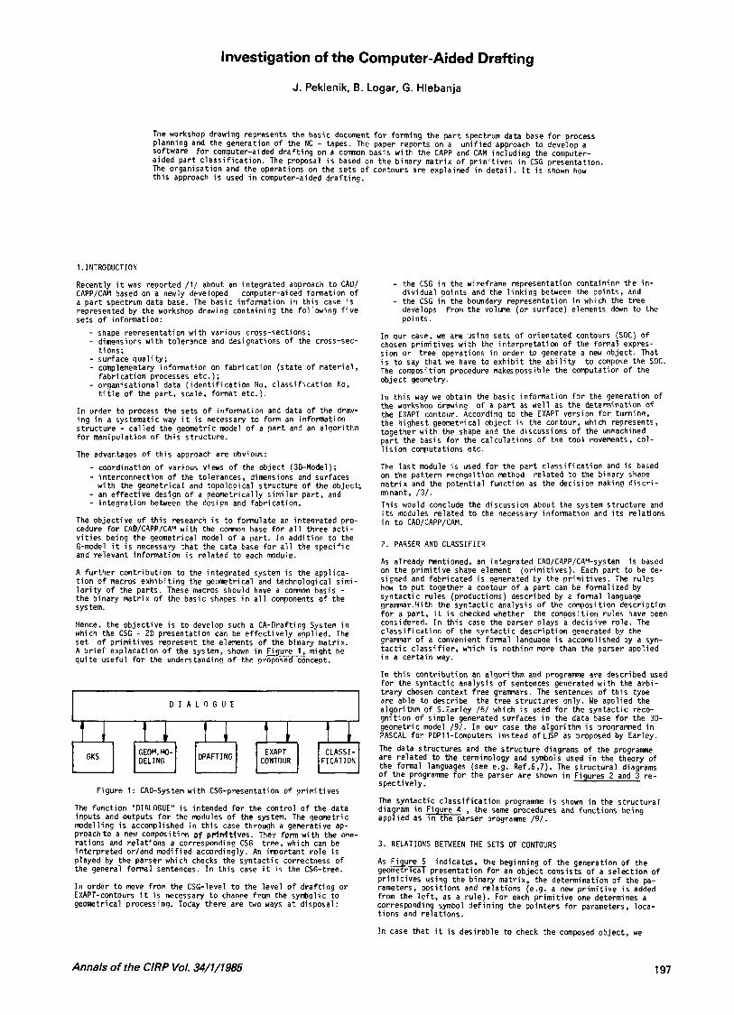
Hence, the ob jec t i ve i s t o develop such a CA-Drafting System i n which the CSG - 20 presentat ion can be e f fec t i ve l y applied. The se t of p r im i t i ves represent the elements o f the b inary matr ix. A b r i e f explanat ion o f the system, shown i n F i ure 1, might be q u i t e use fu l f o r the understanding o f the p r h n c e p t .
D I A L O G U E
EXAPT CLASSI- F I CAT I O N
Figure 1: CAD-System w i t h CSG-presentation o f p r im i t i ves
The func t ion "DI4LOGUE" i s intended f o r the cont ro l o f the data inputs and outputs f o r the modules o f the system. The geometric model l ing i s accomplished i n t h i s case through a generat ive ap- p roachto a new cornposition of pr imt t tves . T5e. form w i t h the one- ra t i ons and re la t i ons a correspondinq CSG t ree , which can be i n te rp re ted or/and modif ied accordingly. An inpor tan t r o l e i s played by the parser which checks the syn tac t i c correctness o f the general formal sentences. I n t h i s case i t i s the CSG-tree.
I n order t o move from the CSG-level t o the l eve l o f d r a f t i n g o r EXAPT-contours i t i s necessary t o chanw from the symbolic t o geometrical processing. Today there are two ways a t disposal:
- the CSG i n the wireframe representat ion containinn the i n - d i v idua l po in ts and the l i n k i n g between the po in ts , and - the CSG i n the boundary representat ion i n which the t ree develops po in ts .
from the volume ( o r surface) elements down t o the
I n our case, we are usina sets o f o r ien ta ted contours (SOC) of chosen p r im i t i ves w i th the i n te rp re ta t i on o f the formal expres- s ion o r t ree operations i n order t o generate a new object . That i s t o say t h a t we have t o e x h i b i t the a b i l i t y The composition procedure makes poss ib le the conputation o f the ob jec t geometry.
I n t h i s way we ob ta in the basic in fo rmat ion f o r the generation o f the workshop drawing o f a p a r t as w e l l as the d e t e n i n a t i o n o f the EXAPT contour. According t o the EXAPT version f o r tu rn inn , the highest geometrical ob jec t i s the contour, which represents, together w i t h the shape and the discussions o f the unmachined p a r t the basis f o r the ca lcu la t ions o f the t o o l movements, co l - l i s i o n computations etc.
The l a s t module i s used f o r the p a r t c l a s s i f i c a t i o n and i s based on the pa t te rn recogn i t ion nethod re la ted t o the b inary shaoe mat r i x and the po ten t i a l func t ion as the decis ion making d i s c r i - minant, / 3 / . This would conclude the discussion about the system s t ruc tu re and i t s modules r e l a t e d t o the necessary in fo rmat ion and i t s relat ions i n t o CAD/CAPP/CAM.
t o compose the SOC.
2. PARSEF AND CLASSIFIER
As already mentioned, an in tegra ted CAD/CAPP/CAl%ystem on the p r i m i t i v e shape element signed and fab r i ca ted i s generated by the p r im i t i ves . The ru les how t o p u t together a contour o f a p a r t can be formal ized by syn tac t i c ru les (product ions) described by a formal language gramar.!.li t h the syn tac t i c analysis o f the corposi t i o n d e s c r i p t i m f o r a par t , i t i s checked whether the composition ru les have been considered. I n t h i s case the parser plays a dec is ive ro le . The c l a s s i f i c a t i o n o f the syn tac t i c descr ip t ion generated by the g ramar o f a convenient formal languape i s accomolished by a syn- t a c t i c c l a s s i f i e r . which i s no th inn more than the parser apo l ied i n a ce r ta in way.
I n t h i s con t r i bu t i on an a lgor i thm and p r o g r a m are described used f o r the syn tac t i c analysis o f sentences generated w i th the a rb i - t r a r y chosen context f ree gramars . The sentences o f t h i s type are able t o describe the t ree s t ruc tu res only. Ne appl ied the a lqor i thm o f S.Earley /6/ which i s used f o r the syn tac t i c reco- g n i t i o n o f simple generated surfaces i n the data base f o r the 30- geometric model /9/. I n our case the a lgor i thm i s prosrammed i n PASCAL f o r PDP11-Computers ins tead o f LBP as proposed by Earley.
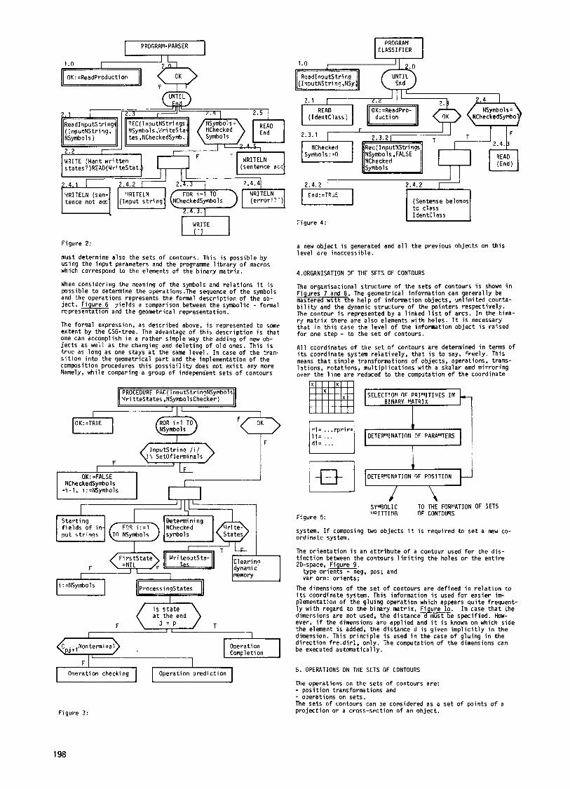
The data s t ruc tu res and the s t ruc tu re diagrams o f the p r o g r a m are re la ted to the terminology and symbols used i n the theory of the formal languages (see e.g. Ref.6-7). The s t ruc tu ra l diagrams of t he programne f o r the parser a re shown i n Figures 2 and 3 re - spec t ive ly .
The syn tac t ic c l a s s i f i c a t i o n programme i s shown i n the s t ruc tu ra l diagram i n F i ure 4 app l ied as b w k - programne /9/ .
i s based (o r im i t i ves ) . Each p a r t t o be de-
the same procedures and func t ions being
3. RELATIONS BETWEEN THE SETS OF CONTOURS
As F i ure 5 indicates, the beginning of the generat ion o f the g e o b presentat ion fo r an ob jec t consists o f a se lec t i on o f p r im i t i ves using the b inary matr ix, the determinat ion o f the pa- rameters, pos i t ions and re la t i ons (e.9. a new p r i m i t i v e i s added from the l e f t , as a ru le ) . For each p r i m i t i v e one determines a corresponding symbol de f in ing the po in te rs f o r parameters, loca- t i ons and re la t i ons .
I n case tha t i t i s des i rab le t o check the composed object , we
Annals of the ClRP Vol. 34/1/1985 197
PROGRAM-PARSER PROGRAM
WRITE (Yant w r i t t e n states?)READ(Yri t e s t a t
* -. I WRITE I , -.
1 4 . 1 r-, 1.4.2 y'(.'y ][.4.41 , VRITELN (sen- 'IRITELN FOR 1 = 1 TO 1441 TELN tence no t aa: ( Input s t r i n g NCheckedSymbols (e r ro r ! ' - )
I i gure 4:
Figure 2:
must determine a lso the se ts o f contours. This i s possible by using the i npu t parameters and the programme l i b r a r y o f macros which correspond to the elements o f the b inary mat r ix .
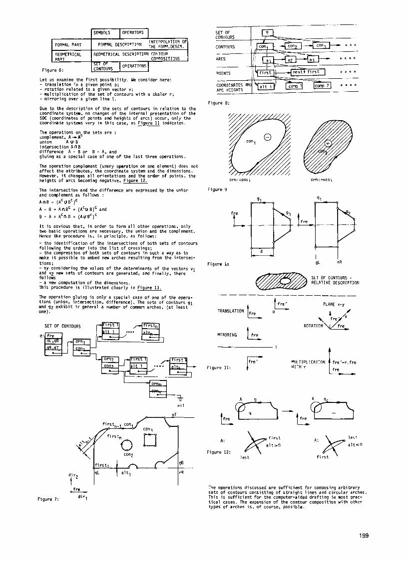
When consider ing the meaning o f the symbols and re la t i ons it i s possible t o determine the operations.The sequence o f the symbols and the operat ions represents the formal descr ip t ion o f the ob- j e c t . Figure 6 y ie lds a comparison between the symbolic - formal representat ion and the geometrical representat ion.
The formal expression, as described above, i s represented to some ex ten t by the CSG-tree. The advantage o f t h i s desc r ip t i on i s t ha t one can accomplish i n a ra the r simple way the adding o f new ob- j e c t s as we l l as the changing and de le t i ng of o l d ones. This i s t rue as long as one stays a t the same l e v e l . I n case o f the t ran- s i t i o n i n t o the geometrical p a r t and the implementation o f the composition procedures t h i s p o s s i b i l i t y does not e x i s t any mare Namely, wh i le comparing a group o f independent se ts o f contours
PROCEDURE P~C(innutStrin?YSymbols Vri t teStates ,NSymbolsChecker)
?----
OK: =TRUE CzI Gs;) ROR i - 1 TO f<T> InputSt r inq /i/
F I
NCheckedSymbol s = i - 1 i:=NSymhols
a new ob jec t i s generated and a l l t he previous objects on t h i s leve l a re inaccessible.
4.ORGANISATION OF THE SETS OF CONTOURS
The organisat ional s t ruc tu re o f t he se ts o f contours i s shown i n Figures 7 and 8. The geometrical in fo rmat ion can general ly be mastered w i t h the he lp o f in fo rmat ion objects, un l im i ted counta- b i l i t y and the dynamic s t ruc tu re o f the po in te rs respec t ive ly . The contour i s represented by a l i nked l i s t o f arcs. I n the bina- ry mat r ix there are a lso elements w i t h holes. It i s necessary tha t i n t h i s case the leve l o f the informat ion ob jec t i s ra ised f o r one step - to the se t o f contours.
A l l coordinates o f the se t o f contours a re determined i n terms o f i t s coordinate system r e l a t i v e l y , t h a t i s t o say, f ree l y . This means t h a t simple t ransformat ions o f objects, operations, t rans- l a t i ons , ro ta t i ons , m u l t i p l i c a t i o n s w i t h a skalar and m i r ro r i ng over the l i n e a re reduced t o the computation o f t he coordinate
I I r l = ... r p r i r =
I I 1-1 I/? DETEWINATION OF POSITION
SYMROLIC '.ID I T T I YG OF CONTOUTS
TO THE FORI'ATION OF SETS
Figure 5:
system. If composing two ob jec ts i t i s requ i red t o se t a new co- o rd ina te system.
The o r i e n t a t i o n i s an a t t r i b u t e o f a contour used f o r the d i s - t i n c t i o n between the contours l i m i t i n a the holes o r the e n t i r e 2D-space, F i ure 9
type o r i h e g . pos; and var orn: o r ien ts ;
The dimensions o f the se t o f contours a re def ined i n r e l a t i o n t o i t s coordinate system. This in fo rmat ion i s used f o r easier im- plementation o f the g lu ing opera t ion which appears q u i t e f requent- l y w i t h regard t o the b inary mat r ix , F i ure lo. I n case t h a t the dimensions are no t used, t he distance-&Z?Te spec i f ied . How- ever, i f the dimensions are app l ied and i t i s known on which s ide the element i s added, the distance d i s given i m p l i c i t l y i n the dimension. This p r i n c i p l e i s used i n the case o f g lu ing i n the d i r e c t i o n fre.dit-1, on ly . The computation o f the dimensions can be executed automat ical ly.
5. OPERATIONS ON THE SETS OF CONTOURS
The operat ions on the sets o f contours are: - pos i t i on t ransformat ions and - operat ions on sets. The se ts o f contours can be considered as a se t o f po in ts o f a p ro jec t i on o r a cross-sect ion o f an ob jec t . Figure 3:
198
I s Y i n L s I OPERATORS I
Figure 6:
Le t us examine the f i r s t p o s s i b i l i t y . We consider here: - t r a n s l a t i o n i n a given p o i n t p; - r o t a t i o n re la ted t o a given vector v; - m u l t i p l i c a t i o n o f t h e se t o f contours w i th a skalar r; - m i r ro r i ng over a given l i n e 1.
Due t o the descr ip t ion o f the sets o f contours i n r e l a t i o n t o the coordinate system, no changes o f the i n te rna l presentat ion o f the SOC (coordinates o f points and heights o f a rcs) occur, on ly the coordinate systems vary i n t h i s case, as Figure 11 ind ica tes .
The operat ions on t h e sets a re : compl ement, A + nC union A U B i n te rsec t i on An6 d i f fe rence A - B o r B - A, and g lu ing as a special case o f one o f t he l a s t th ree operat ions.
The opera t ion complement (unary opera t ion on one element) does no t a f f e c t the a t t r i bu tes , the coordinate system and the dimensions. However, i t changes a l l o r i en ta t i ons and the order o f po in ts , the heights o f arcs becoming negative. Figure 12.
The in te rsec t i on and the d i f f e rence are expressed by the union and compl ement as f o l 1 ows : A ~ B = ( A ~ u B ~ ) ~
A - B = A n B C = (ACU 6)' and B - A = ~~n B = ( A U B ~ ) ~
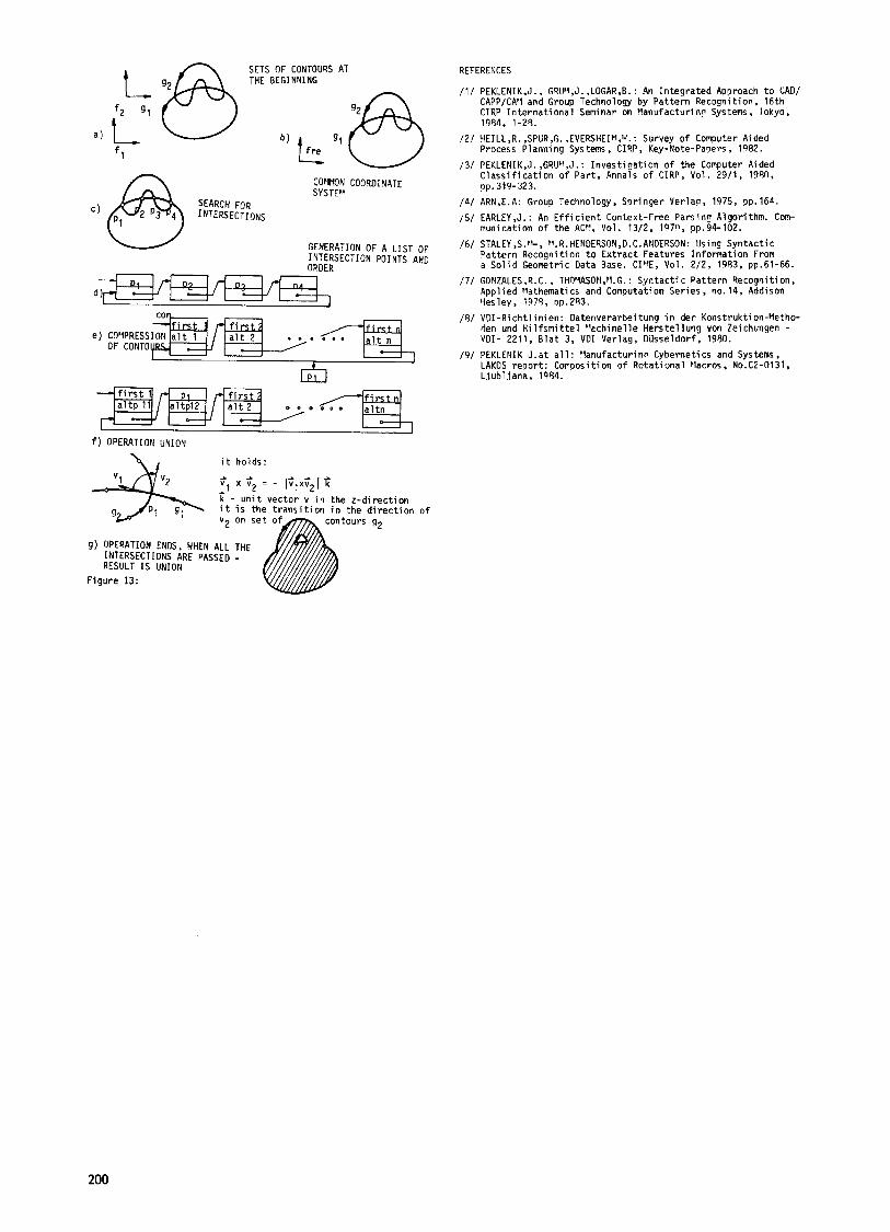
I t i s obvious that, i n order t o form a l l o ther operations, on ly two basic operat ions a re necessary, the union and the complement. Hence the procedure i s , i n p r i nc ip le , as fo l lows: - the i d e n t i f i c a t i o n o f the in te rsec t ions o f both sets o f contours fo l l ow ing the order i n t o the l i s t o f crossings; - the compression o f both sets o f contours i n such a way as t o make i t poss ib le t o embed new arches r e s u l t i n g from the in te rsec- t ions ; - by consider ing the values o f the determinants o f the vectors v1 and vp new sets o f contours a re generated, and f i n a l l y , there fo l lows - a new computation o f the dimensions. This procedure i s i l l u s t r a t e d c l e a r l y i n Figure 13.
The opera t ion g lu ing i s on ly a special case o f one o f the opera- t i ons (union, in te rsec t ion , d i f fe rence) . The sets o f contours g1 and g2 e x h i b i t i n general a number o f c o m n arches, ( a t l e a s t one).
SET OF CONTOURS
9:
Figure 8:
orn: =pos ; orn:=neo;
Figure 9
I-.
Figure l o gL
SET OF CONTOURS - RELATIVE DESCRIPTION
lf.. PLANE X-y TRANSLATION p \j/yf
ROTATION'
Y IRORING ffre 1
Figure 11: aITH r
A n A a-
n i 1 y7)-L p7-j
A: * last
f r e - a l t e 0
f i r s t
a l t 9 J k f i r s t l a s t
A:
Figure 12:
The operat ions discussed are s u f f i c i e n t f o r composing a r b i t r a r y se ts o f contours cons is t ing o f s t r a i g h t l i n e s and c i r c u l a r arches. This i s s u f f i c i e n t f o r the computer-aided d r a f t i n g i n most prac- t i c a l cases. The expansion o f t he contour composition w i t h other types o f arches i s , o f course, poss ib le .
d i r , F igure 7:
199
COfllrON COORDINATE @,, SEARCH FOR SYSTEV
C ) 2 P3 4 INTERSECTIONS
- f i r s t f i rst i e ) COYPRESSION a l t 1 a l t 2
OF CONTO c
W
a l t n . 0 -- c
GENERATION OF A LIST OF INTERSECTION POINTS AND ORDER
- f i r s t 1 P I - f i r s t 4 / . f i r s t a l t p 11 a l t p l 2 a l t 2 o D o o o o a l t n
0- 0-
f ) OPERATION UNION
1' i t holds:
i t
x c2 = - I t( . u n i t vec tor v i n the z - d i r e c t i o n i s the t r a n s i t i o n i n the d i r e c t i o n o f
REFERENCES
/3/
I d l
I 5 1
/6/
/71
/ 5 /
/9/
/1/ PEKLEN1K.J.. G4Ut4,J. ,LOGAR,B. : An I n t e g r a t e d Approach t o C A D I CAPPICA'l and Group Technology by Pat te rn Recognition, 16th CIRP I n t e r n a t i o n a l Seminar on blanufacturino Systems, Tokyo, 1'154, 1-25.
Process Planning Systems, C IRP, Key-Note-Papers, 1982. /2/ VEILL,R. ,SPUR,G. ,EVERSHEIf!,lJ. : Survey o f Computer t i d e d
PEKLENIK,J. ,GRUIq,J.: I n v e s t i g a t i o n o f the Computer Aided C l a s s i f i c a t i o n o f Par t , 4nnals o f C I R P , Vol. 2911, 1990,
ARN,E.A: Group Technology, Spr inger Verlag, 1975, pp. 164. EARLEY , J . : An E f f i c i e n t Context-Free Parsin5 Algorithm. Com- municat ion o f the ACY, Vol. 1312. 1070, pp.94-102. STALEY ,S."-, '4.4. HENDErlSON,D. C.AN0ERSON: Using Syntac t ic Pat te rn Recogni t ion t o E x t r a c t Features I n f o r n a t i o n From a S o l i d Geometric Data Base. CI'rE, Vol. 212, 1953, pp.61-66. GONZALES,R.C., THOMASObl,pl.G.: S y n t a c t i c Pat te rn Recognition, Appl ied frathematics and Computation Ser ies, no. 14, Addison I.lesley, 1974, op.283. V D I - R i c h t l i nien: Datenverarbei tung i n der Konstrukt i on-Metho- den und H i l f s n i t t e l "ach ine l le Hers te l lung von Zeichungen - V D I - 2211, B l a t 3, V D I Verlag, DUsseldorf, 1980. PEKLENIK J .a t a l l : Vanufacturino Cybernetics and Systems, LAKOS repor t : Composition o f Rota t iona l Vacros. No.C2-0131, L jub l jana, 1984.
pp. 319-323.
9) OPERATION ENDS, WHEN ALL INTERSECTIONS ARE PASSED RESULT IS UNION
F igure 13:
200