Embed Size (px)
Citation preview
Investigation of process parameters of electrohydrodynamic jetting for 3D printed PCL fibrous scaffolds with complex geometries. © 2016 Hui Wang, et al. This is an Open Access article distributed under the terms of the Creative Commons Attribution-NonCommercial 4.0 International License (http://creativecommons.org/licenses/by-nc/4.0/), permitting all non-commercial use, distribution, and reproduction in any medium, provided the original work is properly cited.
63
RESEARCH ARTICLE
Investigation of process parameters of electrohydro-dynamic jetting for 3D printed PCL fibrous scaffolds with complex geometries
Hui Wang1, Sanjairaj Vijayavenkataraman2, Yang Wu2, Zhen Shu1, Jie Sun1 and Jerry Fuh Ying Hsi1,2* 1 NUS Suzhou Research Institute (NUSRI), No. 377 Linquan Street, Dushu Lake Science and Education Innovation
District, Suzhou Industrial Park, Suzhou, Jiangsu, China 215123 2 Department of Mechanical Engineering, National University of Singapore, 9 Engineering Drive 1, Singapore 117575
Abstract: Tissue engineering is a promising technology in the field of regenerative medicine with its potential to create tissues de novo. Though there has been a good progress in this field so far, there still exists the challenge of providing a 3D micro-architecture to the artificial tissue construct, to mimic the native cell or tissue environment. Both 3D printing and 3D bioprinting are looked upon as an excellent solution due to their capabilities of mimicking the native tissue architecture layer-by-layer with high precision and appreciable resolution. Electrohydrodynamic jetting (E-jetting) is one type of 3D printing, in which, a high electric voltage is applied between the extruding nozzle and the substrate in order to print highly controlled fibres. In this study, an E-jetting system was developed in-house for the purpose of 3D printing of fibrous scaffolds. The effect of various E-jetting parameters, namely the supply voltage, solution concentra-tion, nozzle-to-substrate distance, stage (printing) speed and solution dispensing feed rate on the diameter of printed fibres were studied at the first stage. Optimized parameters were then used to print Polycaprolactone (PCL) scaffolds of highly complex geometries, i.e., semi-lunar and spiral geometries, with the aim of demonstrating the flexibility and ca-pability of the system to fabricate complex geometry scaffolds and biomimic the complex 3D micro-architecture of na-tive tissue environment. The spiral geometry is expected to result in better cell migration during cell culture and tissue maturation. Keywords: 3D printing, PCL scaffolds, E-jet printing
*Correspondence to: Jerry Fuh Ying Hsi, Department of Mechanical Engineering, National University of Singapore, 9 Engineering Drive 1, Singapore 117575; Email: [email protected]
Received: October 26, 2015; Accepted: November 24, 2015; Published Online: January 5, 2016 Citation: Wang H, Vijayavenkataraman S, Wu Y, et al., 2016, Investigation of process parameters of electrohydrodynamic jetting for 3D printed PCL fibrous scaffolds with complex geometries. International Journal of Bioprinting, vol.2(1): 63–71. http://dx.doi.org/10.18063/IJB.2016.01.005.
1. Introduction
caffolds have a significant role in tissue engi-neering. In brief, cells are cultured in vitro on a scaffold and allowed to migrate, proliferate and
differentiate, which eventually attached to the scaf-
fold and developed into a tissue. Most of the times, the engineered tissue is incubated in a bioreactor to facilitate maturation. The structure and properties of the final engineered tissue predominantly depends on the material, structure and properties of the scaffold. Many requirements are expected in order for scaffolds
S
Investigation of process parameters of electrohydrodynamic jetting for 3D printed PCL fibrous scaffolds with complex geometries
64 International Journal of Bioprinting (2016)–Volume 2, Issue 1
to be successful in engineering a tissue[1–2], namely (i) scaffold should biomimic the native tissue environ-ment as close as possible, (ii) material selection, should be biocompatible and biodegradable, (iii) ap-propriate surface chemistry to promote cell attachment, proliferation and differentiation, (iv) adequate me-chanical properties, and (v) fabrication flexibility to have a variety of shapes and sizes. The utmost cha-llenge with the current tissue engineering techniques is imitation of the native tissue environment. Tradi-tional tissue engineering methods use 2D materials or scaffolds for cell culture and tissue construction. The main drawback of 2D substrate is that it fails to pro-vide the cell with its native architecture. Most impor-tantly, native tissue micro-architecture is highly complex and highly oriented due to its 3D environ-ment. Obviously, when a 3D environment is provided rather than 2D or 2.5D, the cells grow, proliferate and differentiate closer to the native tissue[3–5]. There are several techniques to create a3D environment, such as solvent-casting particulate-leeching, gas foaming, ph-ase separation, melt moulding, solution casting, freeze drying and emulsion freeze drying, however, they suf-fer from the drawback of producing only a foam structure, and not a highly controlled porous 3D mi-cro-architecture, which leads to several other prob-lems[6]. Though microscale fabrication technologies like soft lithography were able to create a microscale resolution scaffold[7–8], they a l s o suffer from several limitations associated with inflexibility in fabricating complex geometries and the optimization of scaffold architecture[9]. Electrospinning is looked at as an al-ternate technology to fabricate nanofibrous scaffolds for tissue engineering applications[10–14] and shows a considerable progress with several reports portraying its successfulness. Nonetheless, electrospinning tech-nology suffers from the limitation of randomly ori-ented fibres and inability to fabricate a controlled uniformly porous scaffolds. 3D printing is currently seen as the potential solution to fabricate layer by layer, controlled 3D porous scaffolds[6,15–19]. A new term known as 3D bioprinting has emerged recently and researchers are working towards the realization of printing functional human organs with this novel technology. An et al.[20] reviewed vastly on various state-of-the-art 3D printing technologies for tissue engineering applications, limitations of the current technologies and the possible future improvements. Electrohydrodynamic Jetting, which is also known as EHD-Jetting or E-jetting is one type of bioprinting
technology. E-jetting has the same working principle as Electrospinning technique which is widely used to fabricate controlled porous scaffolds for tissue engineering applications[21–26]. Various studies were made on the effect of Electrospinning parameters on the electrospun fibres[27–28]. Subsequently, the most important parameters that have been identified were namely, the volumetric charge density, distance from nozzle to collector, initial jet/orifice radius, relaxation time, and viscosity[29]. Numerous novel and hybrid techniques of Electrospinning were developed in or-der to overcome the limitation of non-orientated ran-dom fibres from the Electrospinning process. Bu et al.[30] developed a mechano-electrospinning technique for fabricating oriented nanofibres and the controlled parameter was the moving speed of the substrate. Chanthakulchan et al.[31] developed an Electrospin-ning-based rapid prototyping method for fabrication of patterned scaffolds but only achieved a certain level, due to the challenges of controlling the vibration. Au-yson et al.[32] studied the effect of various parameters of the hybrid Electrospinning / Fused Depositio Mod-elling (FDM) on the fabricated scaffold and concluded that two most important parameters to get a conti-nuous jet are the voltage applied and the standoff dist-ance between the nozzle and the substrate. On the other hand, a low voltage near-field Electrospinning method reported by Bisht et al.[33] was able to pattern nanofi-bres continuously on both 2D and 3D substrates, re-spectively. Besides that, other vital parameters were namely, the viscosity and elasticity of the polymer ink[34].
In this study, an E-jetting setup was built in-house in order to fabricate 3D scaffolds out of PCL material. PCL material is widely used as a biomaterial for scaf-folds which possess extremely good mechanical pro-perties. The structure of the printed scaffold depends on two important elements namely, the fibre diameter and the pore size. The parameters of the E-jetting system, i.e. the supply voltage, solution concentration, nozzle- to-substrate distance, stage (printing) speed and solu-tion dispensing feed rate greatly influences the fibre diameter of the printed structure. Briefly, the relation between these parameters and the fibre diameter were discussed in this work. Parameters were optimized and scaffolds of complex geometries i.e. semi-lunar and spiral shapes have been successfully printed.
2. Experimental Section
2.1 Materials
Acetate (Aladdin A116171, electronic grade, >99.7%)
Hui Wang, Sanjairaj Vijayavenkataraman, Yang Wu, et al.
International Journal of Bioprinting (2016)–Volume 2, Issue 1 65
which is commonly referred to acetic acid was used as the solvent. Polycaprolactone (PCL) pellets with an average molecular weight of 80 kDa (Polycaprolac-tone, Scientific Polymer Products Inc, Ontario, NY) was used as the solute biomaterial. PCL pellets were put in the acetic acid solution (50%, 60%, 70%, 80% and 90%) (w/v) and sonicated by using an ultrasonic sonicator at 30°C and 40 kHz for 3 hours. Then, the mixture was stirred well and re-sonicated for another 1.5 hours in order to obtain a homogeneous solution. The solution was left at room temperature for a while before unloaded it into the syringe for E-jetting pur-pose. Polished silicon wafers with the diameter of 100 mm were used as substrates.
2.2 Experimental Setup
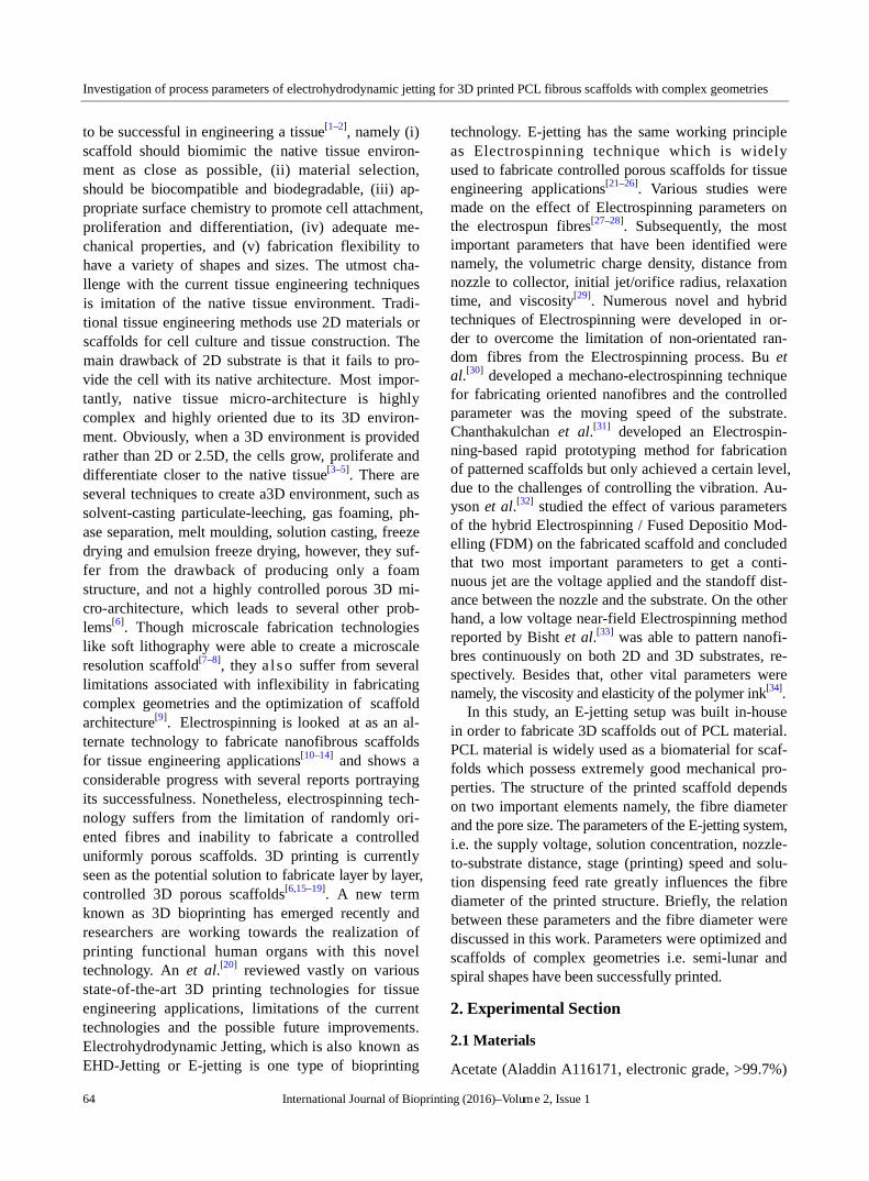
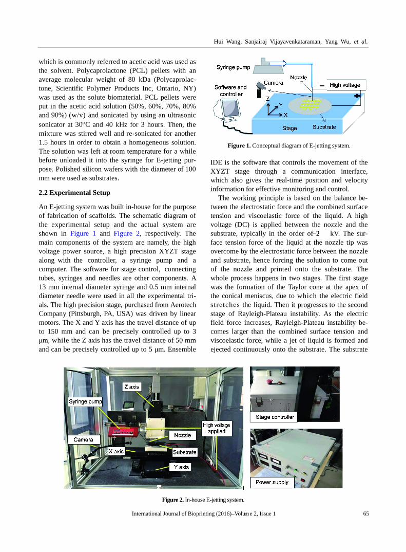
An E-jetting system was built in-house for the purpose of fabrication of scaffolds. The schematic diagram of the experimental setup and the actual system are shown in Figure 1 and Figure 2, respectively. The main components of the system are namely, the high voltage power source, a high precision XYZT stage along with the controller, a syringe pump and a computer. The software for stage control, connecting tubes, syringes and needles are other components. A 13 mm internal diameter syringe and 0.5 mm internal diameter needle were used in all the experimental tri-als. The high precision stage, purchased from Aerotech Company (Pittsburgh, PA, USA) was driven by linear motors. The X and Y axis has the travel distance of up to 150 mm and can be precisely controlled up to 3 μm, while the Z axis has the travel distance of 50 mm and can be precisely controlled up to 5 μm. Ensemble
Figure 1. Conceptual diagram of E-jetting system.
IDE is the software that controls the movement of the XYZT stage through a communication interface, which also gives the real-time position and velocity information for effective monitoring and control.
The working principle is based on the balance be-tween the electrostatic force and the combined surface tension and viscoelastic force of the liquid. A high voltage (DC) is applied between the nozzle and the substrate, typically in the order of 2−3 kV. The sur-face tension force of the liquid at the nozzle tip was overcome by the electrostatic force between the nozzle and substrate, hence forcing the solution to come out of the nozzle and printed onto the substrate. The whole process happens in two stages. The first stage was the formation of the Taylor cone at the apex of the conical meniscus, due to which the electric field stretches the liquid. Then it progresses to the second stage of Rayleigh-Plateau instability. As the electric field force increases, Rayleigh-Plateau instability be-comes larger than the combined surface tension and viscoelastic force, while a jet of liquid is formed and ejected continuously onto the substrate. The substrate
Figure 2. In-house E-jetting system.
Investigation of process parameters of electrohydrodynamic jetting for 3D printed PCL fibrous scaffolds with complex geometries
66 International Journal of Bioprinting (2016)–Volume 2, Issue 1
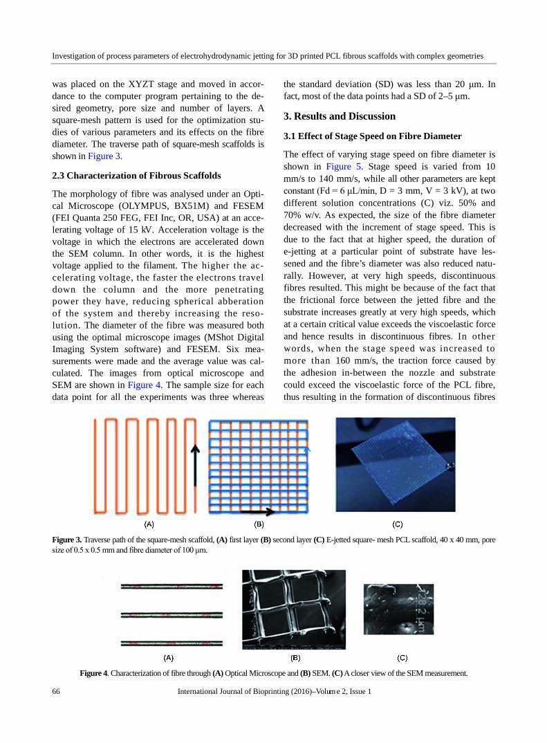
was placed on the XYZT stage and moved in accor-dance to the computer program pertaining to the de-sired geometry, pore size and number of layers. A square-mesh pattern is used for the optimization stu-dies of various parameters and its effects on the fibre diameter. The traverse path of square-mesh scaffolds is shown in Figure 3.
2.3 Characterization of Fibrous Scaffolds
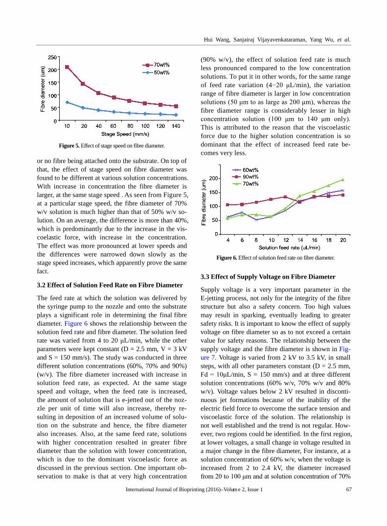
The morphology of fibre was analysed under an Opti-cal Microscope (OLYMPUS, BX51M) and FESEM (FEI Quanta 250 FEG, FEI Inc, OR, USA) at an acce-lerating voltage of 15 kV. Acceleration voltage is the voltage in which the electrons are accelerated down the SEM column. In other words, it is the highest voltage applied to the filament. The higher the ac-celerating voltage, the faster the electrons travel down the column and the more penetrating power they have, reducing spherical abberation of the system and thereby increasing the reso-lution. The diameter of the fibre was measured both using the optimal microscope images (MShot Digital Imaging System software) and FESEM. Six mea-surements were made and the average value was cal-culated. The images from optical microscope and SEM are shown in Figure 4. The sample size for each data point for all the experiments was three whereas
the standard deviation (SD) was less than 20 μm. In fact, most of the data points had a SD of 2–5 μm.
3. Results and Discussion
3.1 Effect of Stage Speed on Fibre Diameter
The effect of varying stage speed on fibre diameter is shown in Figure 5. Stage speed is varied from 10 mm/s to 140 mm/s, while all other parameters are kept constant (Fd = 6 μL/min, D = 3 mm, V = 3 kV), at two different solution concentrations (C) viz. 50% and 70% w/v. As expected, the size of the fibre diameter decreased with the increment of stage speed. This is due to the fact that at higher speed, the duration of e-jetting at a particular point of substrate have les-sened and the fibre’s diameter was also reduced natu-rally. However, at very high speeds, discontinuous fibres resulted. This might be because of the fact that the frictional force between the jetted fibre and the substrate increases greatly at very high speeds, which at a certain critical value exceeds the viscoelastic force and hence results in discontinuous fibres. In other words, when the stage speed was increased to more than 160 mm/s, the traction force caused by the adhesion in-between the nozzle and substrate could exceed the viscoelastic force of the PCL fibre, thus resulting in the formation of discontinuous fibres
Figure 3. Traverse path of the square-mesh scaffold, (A) first layer (B) second layer (C) E-jetted square- mesh PCL scaffold, 40 x 40 mm, pore size of 0.5 x 0.5 mm and fibre diameter of 100 μm.
Figure 4. Characterization of fibre through (A) Optical Microscope and (B) SEM. (C) A closer view of the SEM measurement.
Hui Wang, Sanjairaj Vijayavenkataraman, Yang Wu, et al.
International Journal of Bioprinting (2016)–Volume 2, Issue 1 67
Figure 5. Effect of stage speed on fibre diameter.
or no fibre being attached onto the substrate. On top of that, the effect of stage speed on fibre diameter was found to be different at various solution concentrations. With increase in concentration the fibre diameter is larger, at the same stage speed . As seen from Figure 5, at a particular stage speed, the fibre diameter of 70% w/v solution is much higher than that of 50% w/v so-lution. On an average, the difference is more than 40%, which is predominantly due to the increase in the vis-coelastic force, with increase in the concentration. The effect was more pronounced at lower speeds and the differences were narrowed down slowly as the stage speed increases, which apparently prove the same fact.
3.2 Effect of Solution Feed Rate on Fibre Diameter
The feed rate at which the solution was delivered by the syringe pump to the nozzle and onto the substrate plays a significant role in determining the final fibre diameter. Figure 6 shows the relationship between the solution feed rate and fibre diameter. The solution feed rate was varied from 4 to 20 μL/min, while the other parameters were kept constant (D = 2.5 mm, V = 3 kV and S = 150 mm/s). The study was conducted in three different solution concentrations (60%, 70% and 90%) (w/v). The fibre diameter increased with increase in solution feed rate, as expected. At the same stage speed and voltage, when the feed rate is increased, the amount of solution that is e-jetted out of the noz-zle per unit of time will also increase, thereby re-sulting in deposition of an increased volume of solu-tion on the substrate and hence, the fibre diameter also increases. Also, at the same feed rate, solutions with higher concentration resulted in greater fibre diameter than the solution with lower concentration, which is due to the dominant viscoelastic force as discussed in the previous section. One important ob-servation to make is that at very high concentration
(90% w/v), the effect of solution feed rate is much less pronounced compared to the low concentration solutions. To put it in other words, for the same range of feed rate variation (4−20 μL/min), the variation range of fibre diameter is larger in low concentration solutions (50 μm to as large as 200 μm), whereas the fibre diameter range is considerably lesser in high concentration solution (100 μm to 140 μm only). This is attributed to the reason that the viscoelastic force due to the higher solution concentration is so dominant that the effect of increased feed rate be-comes very less.
Figure 6. Effect of solution feed rate on fibre diameter.
3.3 Effect of Supply Voltage on Fibre Diameter
Supply voltage is a very important parameter in the E-jetting process, not only for the integrity of the fibre structure but also a safety concern. Too high values may result in sparking, eventually leading to greater safety risks. It is important to know the effect of supply voltage on fibre diameter so as to not exceed a certain value for safety reasons. The relationship between the supply voltage and the fibre diameter is shown in Fig-ure 7. Voltage is varied from 2 kV to 3.5 kV, in small steps, with all other parameters constant (D = 2.5 mm, Fd = 10μL/min, S = 150 mm/s) and at three different solution concentrations (60% w/v, 70% w/v and 80% w/v). Voltage values below 2 kV resulted in disconti-nuous jet formations because of the inability of the electric field force to overcome the surface tension and viscoelastic force of the solution. The relationship is not well established and the trend is not regular. How-ever, two regions could be identified. In the first region, at lower voltages, a small change in voltage resulted in a major change in the fibre diameter, For instance, at a solution concentration of 60% w/v, when the voltage is increased from 2 to 2.4 kV, the diameter increased from 20 to 100 μm and at solution concentration of 70%

Investigation of process parameters of electrohydrodynamic jetting for 3D printed PCL fibrous scaffolds with complex geometries
68 International Journal of Bioprinting (2016)–Volume 2, Issue 1
w/v, when the voltage is increased from 2 to 2.4 kV, the diameter increased from 55 to 95 μm. This is fol-lowed by the second region, where the effect of in-creased voltage has less pronounced effect on the fibre diameter. This may be due to the reason that in region one, there lies the transition point at which the electric field force reaches a critical value and when it exceeds the combined effect of surface tension and viscoelastic forces. However, at a higher solution concentration, the trend looks murky and no stable pattern and the effect is also less pronounced, due to the dominant viscoelas-tic force. This may also be attributed to the complex interaction between the supply voltage and nozzle-to- substrate distance, which goes hand in hand.
Figure 7. Effect of supply voltage on fibre diameter.
3.4 Effect of Nozzle-to-substrate Distance on Fibre Diameter
Another important parameter which plays a significant role in the E-jetting process is the gap between the nozzle and the substrate. This parameter works rela-tive to the supply voltage, i.e., if the gap is very small, applying a higher voltage will result in sparking and if the gap is very large, a very high voltage is required to overcome the surface tension and viscoelastic forces of the solution. The relationship between the nozzle- to-substrate distance and the fibre diameter is shown in Figure 8. Nozzle-to-substrate distance is varied from 1.5 to 3.5 mm, in small steps, with all other pa-rameters constant (V = 2.5 kV, Fd = 10μL/min, S = 150 mm/s) and at three different solution concentra-tions (60% w/v, 70% w/v and 80% w/v). Values below 1.5 mm resulted in sparking. The observed relation-ship has no regular trend. But certain important ob-servations can be made. While at lower values of gap, the fibre diameter increases at some concentrations and decreases at some other concentrations when the gap is increased, eventually there is a plateau region,
where the fibre diameter doesn’t vary much and is sta-ble. After a certain higher value of nozzle-to-substrate distance, the fibre diameter tends to decrease drasti-cally. This is due to the reason that when the gap is larger, at the same supply voltage, the electric field force at the nozzle tip reduces greatly and hence una-ble to overcome the surface tension and viscoelastic forces and also the fibres were not very stable and discontinuous. The trend is a bit different at very high solution concentration; in the plateau (middle) region where for other lower concentrations (60% w/v, 70% w/v) the fibre diameter does not vary much, it de-creases in the higher concentration solution (80% w/v), again due to the dominant viscoelastic force.
Figure 8. Effect of nozzle-to-substrate distance on fibre diameter.
3.5 3D Printing of PCL Scaffolds with Complex Geometries
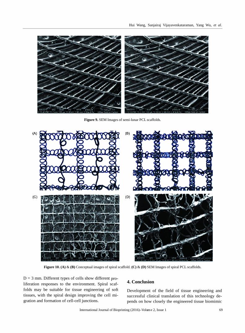
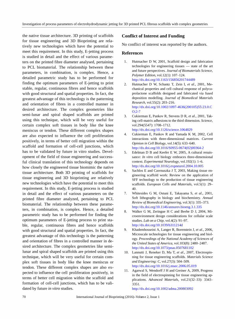
From the parametric study, the E-jetting process was optimized and range for each parameter is obtained so as to get stable, continuous E-jetting fibres. The concentration of the PCL solution was fixed at 70% w/v, stage speed at 150 mm/s, supply voltage 2.5 to 3 kV, solution feed rate 4−10μL/min and nozzle -to-substrate distance 2.5 or 3 mm for all the subsequent experimental trials. Scaffolds of different geometries, with complex architecture were printed. Semi-lunar or curved scaf-folds are printed as shown in Figure 9. This geometry is necessary for reconstruction of soft tissues espe-cially the knee meniscus[35]. The E-jetting parameters were C = 70%, Fd = 8uL/min, V = 3 kV, S = 150 mm/s and D = 2.5 mm. Several trials were made and the fibre diameter measured was 90 ± 5 µm. A novel spir-al scaffold was also printed as shown in Figure 10 for the first time. The E-jetting parameters were, for Fig-ure 10C, C = 70%, Fd = 6 uL/min, V = 2.5 kV, S = 100 mm/s and D = 3 mm, and for Figure 10D, C = 70%, Fd = 0.4 uL/min, V = 2.55 kV, S = 100 mm/s and
Hui Wang, Sanjairaj Vijayavenkataraman, Yang Wu, et al.
International Journal of Bioprinting (2016)–Volume 2, Issue 1 69
Figure 9. SEM Images of semi-lunar PCL scaffolds.
Figure 10. (A) & (B) Conceptual images of spiral scaffold. (C) & (D) SEM Images of spiral PCL scaffolds.
D = 3 mm. Different types of cells show different pro-liferation responses to the environment. Spiral scaf-folds may be suitable for tissue engineering of soft tissues, with the spiral design improving the cell mi-gration and formation of cell-cell junctions.
4. Conclusion
Development of the field of tissue engineering and successful clinical translation of this technology de-pends on how closely the engineered tissue biomimic
Investigation of process parameters of electrohydrodynamic jetting for 3D printed PCL fibrous scaffolds with complex geometries
70 International Journal of Bioprinting (2016)–Volume 2, Issue 1
the native tissue architecture. 3D printing of scaffolds for tissue engineering and 3D Bioprinting are rela-tively new technologies which have the potential to meet this requirement. In this study, E-jetting process is studied in detail and the effect of various parame-ters on the printed fibre diameter analysed, pertaining to PCL biomaterial. The relationship between these parameters, in combination, is complex. Hence, a detailed parametric study has to be performed for finding the optimum parameters of E-jetting to print stable, regular, continuous fibres and hence scaffolds with good structural and spatial properties. In fact, the greatest advantage of this technology is the patterning and orientation of fibres in a controlled manner in desired architecture. The complex geometries like semi-lunar and spiral shaped scaffolds are printed using this technique, which will be very useful for certain complex soft tissues in body like the knee meniscus or tendon. These different complex shapes are also expected to influence the cell proliferation positively, in terms of better cell migration within the scaffold and formation of cell-cell junctions, which has to be validated by future in vitro studies. Devel-opment of the field of tissue engineering and success-ful clinical translation of this technology depends on how closely the engineered tissue biomimic the native tissue architecture. Both 3D printing of scaffolds for tissue engineering and 3D bioprinting are relatively new technologies which have the potential to meet this requirement. In this study, E-jetting process is studied in detail and the effect of various parameters on the printed fibre diameter analyzed, pertaining to PCL biomaterial. The relationship between these parame-ters, in combination, is complex. Hence, a detailed parametric study has to be performed for finding the optimum parameters of E-jetting process to print sta-ble, regular, continuous fibres and hence scaffolds with good structural and spatial properties. In fact, the greatest advantage of this technology is the patterning and orientation of fibres in a controlled manner in de-sired architecture. The complex geometries like semi- lunar and spiral shaped scaffolds are printed using this technique, which will be very useful for certain com-plex soft tissues in body like the knee meniscus or tendon. These different complex shapes are also ex-pected to influence the cell proliferation positively, in terms of better cell migration within the scaffold and formation of cell-cell junctions, which has to be vali-dated by future in vitro studies.
Conflict of Interest and Funding
No conflict of interest was reported by the authors.
References
1. Hutmacher D W, 2001, Scaffold design and fabrication technologies for engineering tissues — state of the art and future perspectives. Journal of Biomaterials Science, Polymer Edition, vol.12(1): 107–124. http://dx.doi.org/10.1163/156856201744489
2. Hutmacher D W, Schantz T, Zein I, et al., 2001, Me-chanical properties and cell cultural response of polyca-prolactone scaffolds designed and fabricated via fused deposition modelling. Journal of Biomedical Materials Research, vol.55(2): 203–216. http://dx.doi.org/10.1002/1097-4636(200105)55:23.0.CO;2-7
3. Cukierman E, Pankov R, Stevens D R, et al., 2001, Tak-ing cell-matrix adhesions to the third dimension. Science, vol.294(5547): 1708–1712. http://dx.doi.org/10.1126/science.1064829
4. Cukierman E, Pankov R and Yamada K M, 2002, Cell interactions with three-dimensional matrices. Current Opinion in Cell Biology, vol.14(5): 633–640. http://dx.doi.org/10.1016/S0955-0674(02)00364-2
5. Edelman D B and Keefer E W, 2005, A cultural renais-sance: In vitro cell biology embraces three-dimensional context. Experimental Neurology, vol.192(1): 1–6. http://dx.doi.org/10.1016/j.expneurol.2004.10.005
6. Sachlos E and Czernuszka J T, 2003, Making tissue en-gineering scaffold work: Review on the application of SFF technology to the production of tissue engineering scaffolds. European Cells and Materials, vol.5(1): 29– 40.
7. Whitesides G M, Ostuni E, Takayama S, et al., 2001, Soft lithography in biology and biochemistry. Annual Review of Biomedical Engineering, vol.3(1): 335–373. http://dx.doi.org/10.1146/annurev.bioeng.3.1.335
8. Walker G M, Zeringue H C and Beebe D J, 2004, Mi-croenvironment design considerations for cellular scale studies. Lab on a Chip, vol.4(2): 91–97. http://dx.doi.org/10.1039/b311214d
9. Khademhosseini A, Langer R, Borenstein J, et al., 2006, Microscale technologies for tissue engineering and biol-ogy. Proceedings of the National Academy of Sciences of the United States of America, vol.103(8): 2480–2487. http://dx.doi.org/10.1073/pnas.0507681102
10. Lannutti J, Reneker D, Ma T, et al., 2007, Electrospin-ning for tissue engineering scaffolds. Materials Science and Engineering: C, vol.27(3): 504–509. http://dx.doi.org/10.1016/j.msec.2006.05.019
11. Agarwal S, Wendorff J H and Greiner A, 2009, Progress in the field of electrospinning for tissue engineering ap-plications. Advanced Materials, vol.21(32–33): 3343– 3351. http://dx.doi.org/10.1002/adma.200803092
Hui Wang, Sanjairaj Vijayavenkataraman, Yang Wu, et al.
International Journal of Bioprinting (2016)–Volume 2, Issue 1 71
12. Li W J, Laurencin C T, Caterson E J, et al., 2002, Elec-trospun nanofibrous structure: A novel scaffold for tissue engineering. Journal of Biomedical Materials Research, vol.60(4): 613–621. http://dx.doi.org/10.1002/jbm.10167
13. Sill T J and von Recum H A, 2008, Electrospinning: Ap-plications in drug delivery and tissue engineering. Bio-materials, vol.29(13): 1989–2006. http://dx.doi.org/10.1016/j.biomaterials.2008.01.011
14. Yang F, Murugan R, Wang S, et al., 2005, Electrospin-ning of nano/micro scale poly (L-lactic acid) aligned fi-bers and their potential in neural tissue engineering. Biomaterials, vol.26(15): 2603–2610. http://dx.doi.org/10.1016/j.biomaterials.2004.06.051
15. Richards D J, Tan Y, Jia J, et al., 2013, 3D printing for tissue engineering. Israel Journal of Chemistry, vol.53(9–10): 805–814. http://dx.doi.org/10.1002/ijch.201300086
16. Mironov V, Boland T, Trusk T, et al., 2003, Organ print-ing: Computer-aided jet-based 3D tissue engineering. Trends in Biotechnology, vol.21(4): 157–161. http://dx.doi.org/0.1016/S0167-7799(03)00033-7
17. Hollister S J, 2005, Porous scaffold design for tissue en-gineering. Nature Materials, vol.4(7): 518–524. http://dx.doi.org/10.1038/nmat1421
18. Boland T, Xu T, Damon B, et al., 2006, Application of inkjet printing to tissue engineering. Biotechnology Journal, vol.1(9): 910–917. http://dx.doi.org/10.1002/biot.200600081
19. Yeong W Y, Chua C K, Leong K F, et al., 2004, Rapid prototyping in tissue engineering: Challenges and poten-tial. Trends in Biotechnology, vol.22(12): 643–652. http://dx.doi.org/10.1016/j.tibtech.2004.10.004
20. An J, Teoh J E M, Suntornnond R, et al., 2015, Design and 3D printing of scaffolds and tissues. Engineering, vol.1(2), 261–268. http://dx.doi.org/10.15302/J-ENG-2015061
21. Gupta A, Seifalian A M, Ahmad Z, et al., 2007, Novel electrohydrodynamic printing of nanocomposite biopo-lymer scaffolds. Journal of Bioactive and Compatible Polymers, vol.22(3), 265–280. http://dx.doi.org/10.1177/0883911507078268
22. Wei C and Dong J, 2013, Direct fabrication of high-res-olution three-dimensional polymeric scaffolds using ele-ctrohydrodynamic hot jet plotting. Journal of Microme-chanics and Microengineering, vol.23(2): 025017. http://dx.doi.org/10.1088/0960-1317/23/2/025017
23. Ahmad Z, Rasekh M and Edirisinghe M, 2010, Electro-hydrodynamic direct writing of biomedical polymers and composites. Macromolecular Materials and Engineering, vol.295(4): 315–319. http://dx.doi.org/10.1002/mame.200900396
24. Li J L, Cai Y L, Guo Y L, et al., 2014, Fabrication of three-dimensional porous scaffolds with controlled fila-ment orientation and large pore size via an improved E-jetting technique. Journal of Biomedical Materials Res-
earch Part B: Applied Biomaterials, vol.102(4): 651–658. http://dx.doi.org/10.1002/jbm.b.33043
25. Gasperini L, Maniglio D, Motta A, et al., 2014, An elec-trohydrodynamic bioprinter for alginate hydrogels con-taining living cells. Tissue Engineering Part C: Methods, vol.21(2): 123–132. http://dx.doi.org/10.1089/ten.TEC.2014.0149
26. Cai Y, Li J L, Poh C K, et al., 2013, Collagen grafted 3D polycaprolactone scaffolds for enhanced cartilage rege-neration. Journal of Materials Chemistry B, vol.1(43): 5971–5976. http://dx.doi.org/0.1039/C3TB20680G
27. Doshi J and Reneker D H, 1993, Electrospinning process and applications of electrospun fibers, In Industry Ap-plications Society Annual Meeting, Conference Record of the 1993 IEEE: 1698–1703.
28. Mitchell G R, Ahn K H and Davis F J, 2011, The poten-tial of electrospinning in rapid manufacturing processes. Virtual and Physical Prototyping, vol.6(2): 63–77. http://dx.doi.org/10.1080/17452759.2011.590387
29. Thompson C J, Chase G G, Yarin A L, et al., 2007, Ef-fects of parameters on nanofiber diameter determined from electrospinning model. Polymer, vol.48(23): 6913– 6922. http://dx.doi.org/10.1016/j.polymer.2007.09.017
30. Bu N, Huang Y, Wang X, et al., 2012, Continuously tun-able and oriented nanofiber direct-written by mechano- electrospinning. Materials and Manufacturing Processes, vol.27(12): 1318–1323. http://dx.doi.org/10.1080/10426914.2012.700145
31. Chanthakulchan A, Koomsap P, Auyson K, et al., 2015, Development of an electrospinning-based rapid proto-typing for scaffold fabrication. Rapid Prototyping Jour-nal, vol.21(3): 329–339. http://dx.doi.org/10.1108/RPJ-11-2013-0119
32. Auyson K, Koomsap P, Chanthakulchan A, et al., 2013, Investigation of applying electrospinning in fused depo-sition modeling for scaffold fabrication. In High Value Manufacturing: Advanced Research in Virtual and Rapid Prototyping, Proceedings of the 6th International Confe-rence on Advanced Research in Virtual and Rapid Pro-totyping, CRC Press: 149.
33. Bisht G S, Canton G, Mirsepassi A, et al., 2011, Con-trolled continuous patterning of polymeric nanofibers on three-dimensional substrates using low-voltage near-field Electrospinning. Nano Letters, vol.11(4): 1831–1837. http://dx.doi.org/10.1021/nl2006164
34. Chang C, Limkrailassiri K and Lin L, 2008, Continuous near-field electrospinning for large area deposition of orderly nanofiber patterns. Applied Physics Letters, vol.93(12): 123111. http://dx.doi.org/10.1063/1.2975834
35. Li J L, Guo Y L, Thian E S, et al., 2013, 3-Dimensional meniscal fibrillar scaffolds, apparatus and process for the fabrication thereof, UK Patent filing, 2013. Application No. 1315074.3.


![Experimental investigation on the effects of process ...Experimental investigation on the effects of process parameters ... et al. [11] monitored the weld joint strength in pulsed](https://img.pdfslide.us/doc/110x75/5f1202453849b60c8e74f2c4/experimental-investigation-on-the-effects-of-process-experimental-investigation.jpg)


![Investigation of Process Parameters during MIG …taking welding current, arc voltage, welding speed, heat input rate as welding parameters. Rakesh kumar et al., [2], Satish kumar](https://img.pdfslide.us/doc/110x75/5e6c0ac208da340d900ef82d/investigation-of-process-parameters-during-mig-taking-welding-current-arc-voltage.jpg)