Embed Size (px)
Citation preview

Investigation of Meteorological Tower Siting Criteria
Ken SejkoraEntergy Nuclear Northeast – Pilgrim
Station
Presented at the 15th Annual RETS-REMP WorkshopWilmington, NC / 27-29 June 2005

Tower Siting Criteria Safety Guide 23 (1972) Regulatory Guide 1.23 – draft, never formally
issued Proposed Revision 1 to Regulatory Guide 1.23
(1980) NUREG-0654 (1980) Second Proposed Revision 1 to Regulatory Guide
1.23 (1986) ANSI/ANS-2.5-1984 (1984) ANSI/ANS-3.11-2000 (2000)

Safety Guide 23 - 1972 “The tower or mast should be sited
at approximately the same elevation as finished plant grade and in an area where plant structures will have little or no influence on the meteorological measurements.”

Proposed Revision 1 to Regulatory Guide 1.23 - 1980
Same requirements as Safety Guide 23, plus Located upwind of heat dissipating structures Height of natural & man-made obstructions
lower than measuring level out to a horizontal distance of 10 times the sensor-height
Instrument booms oriented into prevailing wind to minimize influence of tower
Aspirated temperature shields
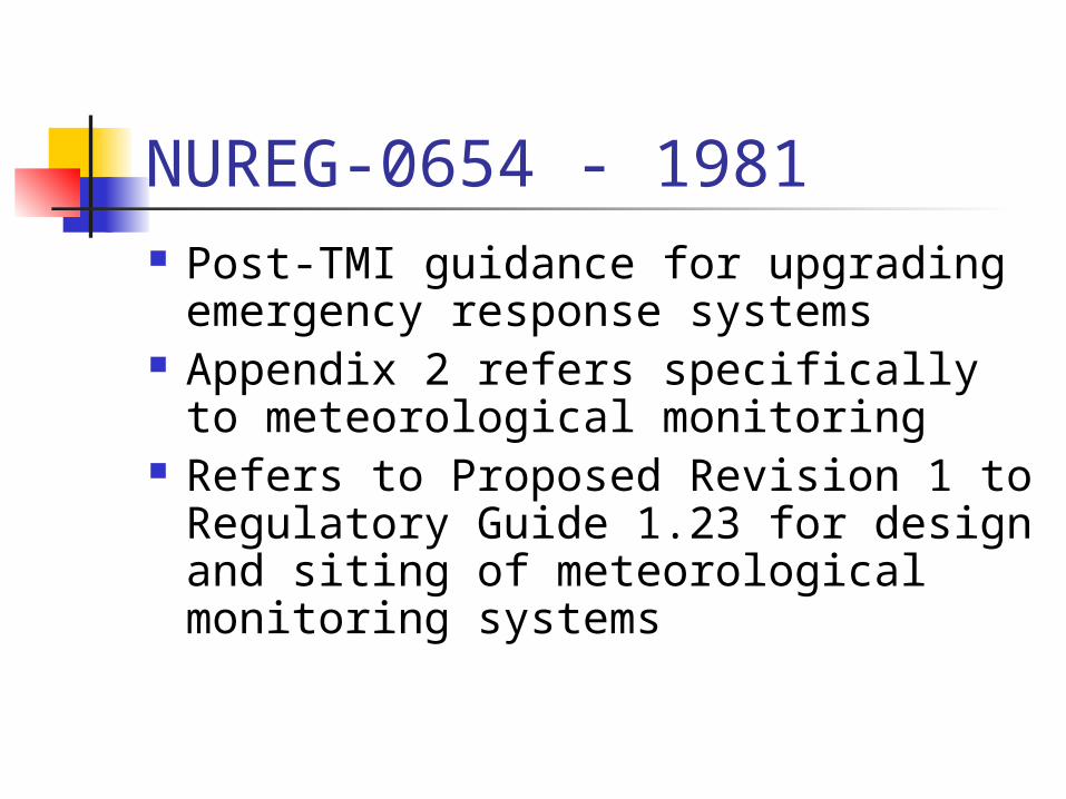
NUREG-0654 - 1981 Post-TMI guidance for upgrading
emergency response systems Appendix 2 refers specifically to
meteorological monitoring Refers to Proposed Revision 1 to
Regulatory Guide 1.23 for design and siting of meteorological monitoring systems
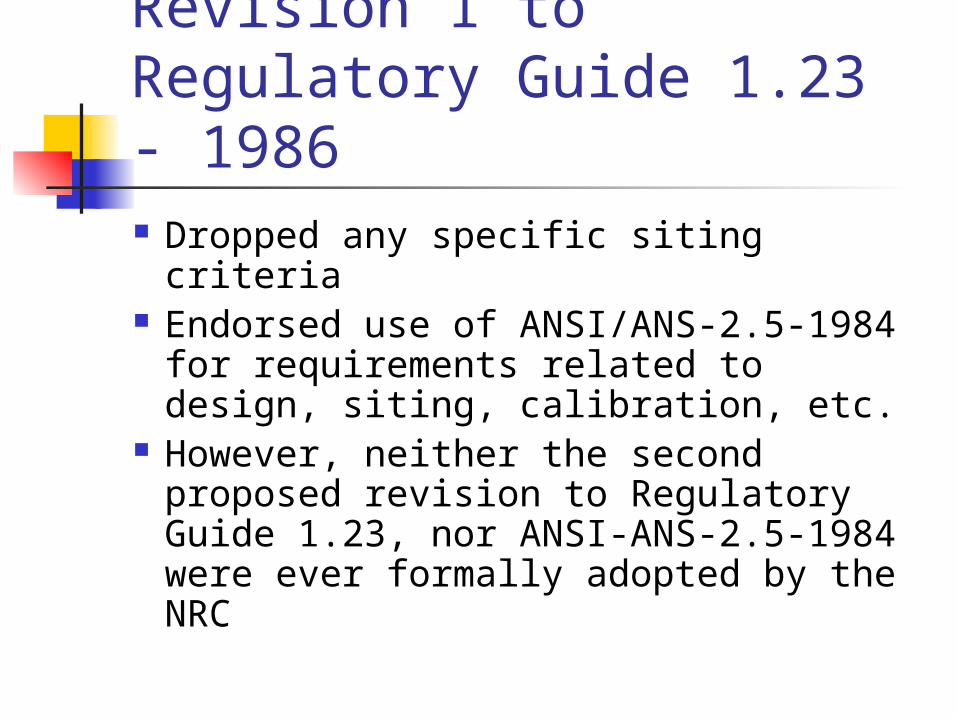
Second Proposed Revision 1 to Regulatory Guide 1.23 - 1986 Dropped any specific siting criteria Endorsed use of ANSI/ANS-2.5-
1984 for requirements related to design, siting, calibration, etc.
However, neither the second proposed revision to Regulatory Guide 1.23, nor ANSI-ANS-2.5-1984 were ever formally adopted by the NRC

ANSI-ANS-2.5-1984 “The meteorological tower site
shall represent as closely as possible the same meteorological characteristics as the region into which any airborne material will be released”
What about ground-level effluents released ‘on-site’?
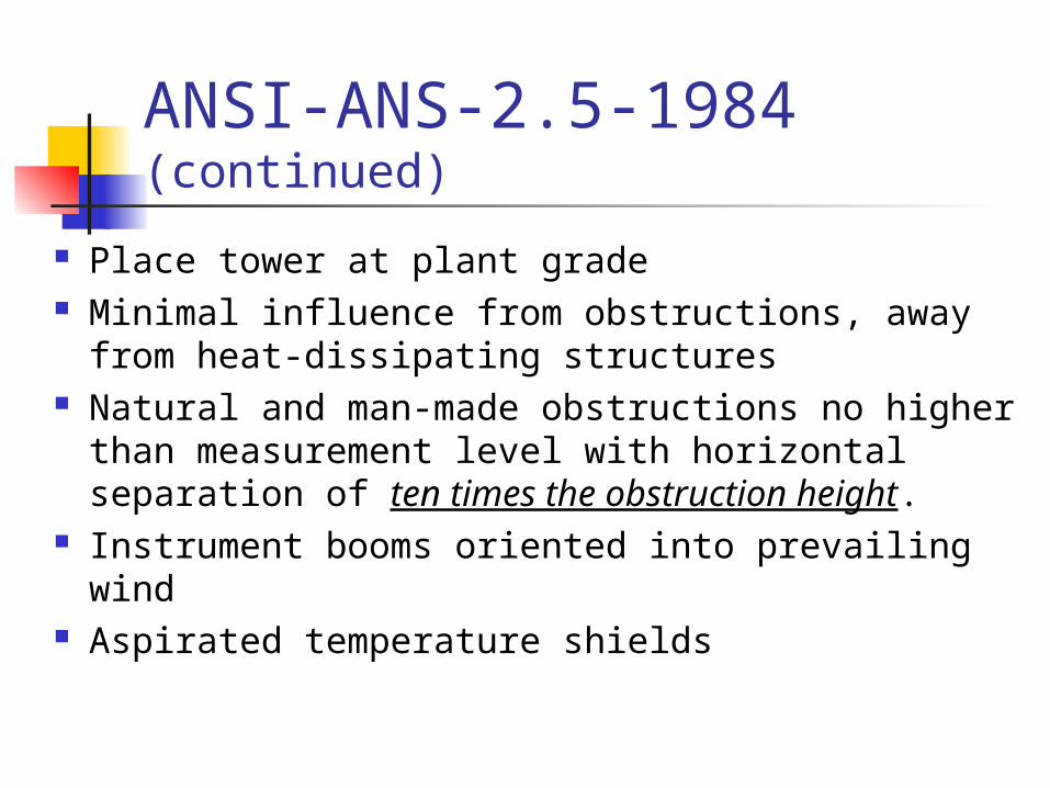
ANSI-ANS-2.5-1984 (continued)
Place tower at plant grade Minimal influence from obstructions, away from
heat-dissipating structures Natural and man-made obstructions no higher
than measurement level with horizontal separation of ten times the obstruction height.
Instrument booms oriented into prevailing wind Aspirated temperature shields

ANSI/ANS-3.11-2000 Much more detailed guidance than previous Guidance provided for flat-terrain, complex-land,
and complex-water sites Locate tower away from obstacles (buildings,
cooling towers, trees, ponds, large paved areas) in flat terrain.
Separation between anemometer and obstruction should be ten time obstruction height; can be reduced to 5X for objects with cross-sectional dimension of 1 meter (utility poles, small trees)

ANSI/ANS-3.11-2000 (continued)
Wind instruments mounted two tower widths away from tower, in upwind direction
Avoid air modifications by heat and moisture sources, water bodies, large parking lots; tower should not be located on or near man-made surfaces such as concrete, asphalt, etc.
Aspirated temperature shields

Ideal vs. Realistic Reg Guide and ANSI/ANS standards
provide standard guidance with the intent of providing consistent siting, while minimizing effects of physical factors
Is such guidance/requirement realistic? Does it represent real conditions on-site, especially for on-site ground-level release points?
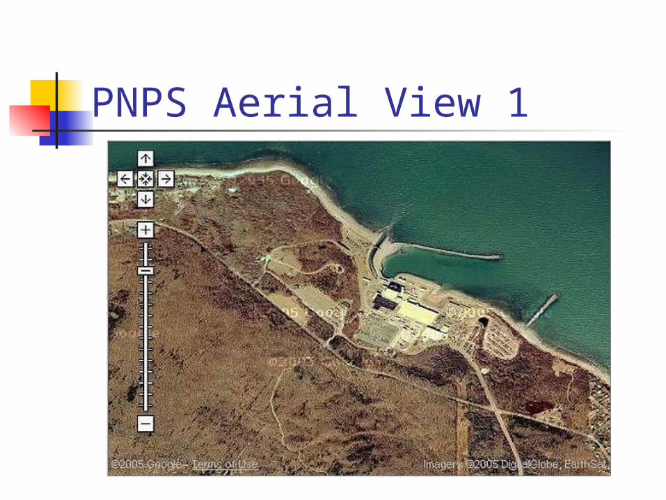
PNPS Aerial View 1

PNPS Aerial View 2

Ground-level Release Points
Plant grade at 23 feet above Mean Sea Level
Reactor Building Vent 158 ft above plant grade, 181 ft MSL 15 ft above reactor building roof Nominal flow rate ~150,000 scfm, 1800 ft/min
Turbine Building Roof Exhausters 85 ft above plant grade, 108 ft MSL 1 to 6 fans (2 typical), at 35,000 scfm each

Primary Met Tower Located 1350 ft WNW from on-site
release point Guyed tower 220 ft tall, base at 80 ft MSL
WS,WD,Temp sensors at 33 ft, 113 ft MSL WS,WD,Temp sensors at 220 ft, 300 ft MSL Upper level corresponds to elevated release
point, 335 ft stack at 65 ft MSL (400 ft MSL)
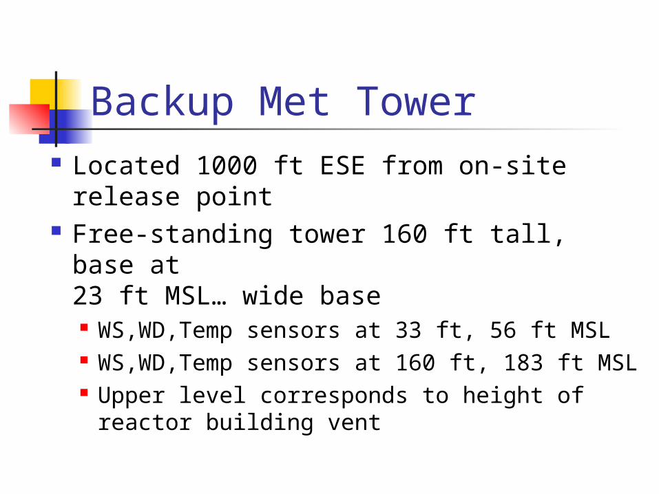
Backup Met Tower Located 1000 ft ESE from on-site
release point Free-standing tower 160 ft tall, base at
23 ft MSL… wide base WS,WD,Temp sensors at 33 ft, 56 ft MSL WS,WD,Temp sensors at 160 ft, 183 ft MSL Upper level corresponds to height of
reactor building vent
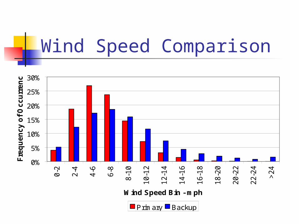
Wind Speed Comparison
0%
5%
10%
15%
20%
25%
30%
0-2
2-4
4-6
6-8
8-10
10-12
12-14
14-16
16-18
18-20
20-22
22-24
>24
Wind Speed Bin - mph
Fre
qu
en
cy
of
Oc
cu
rre
nc
e
Primary Backup
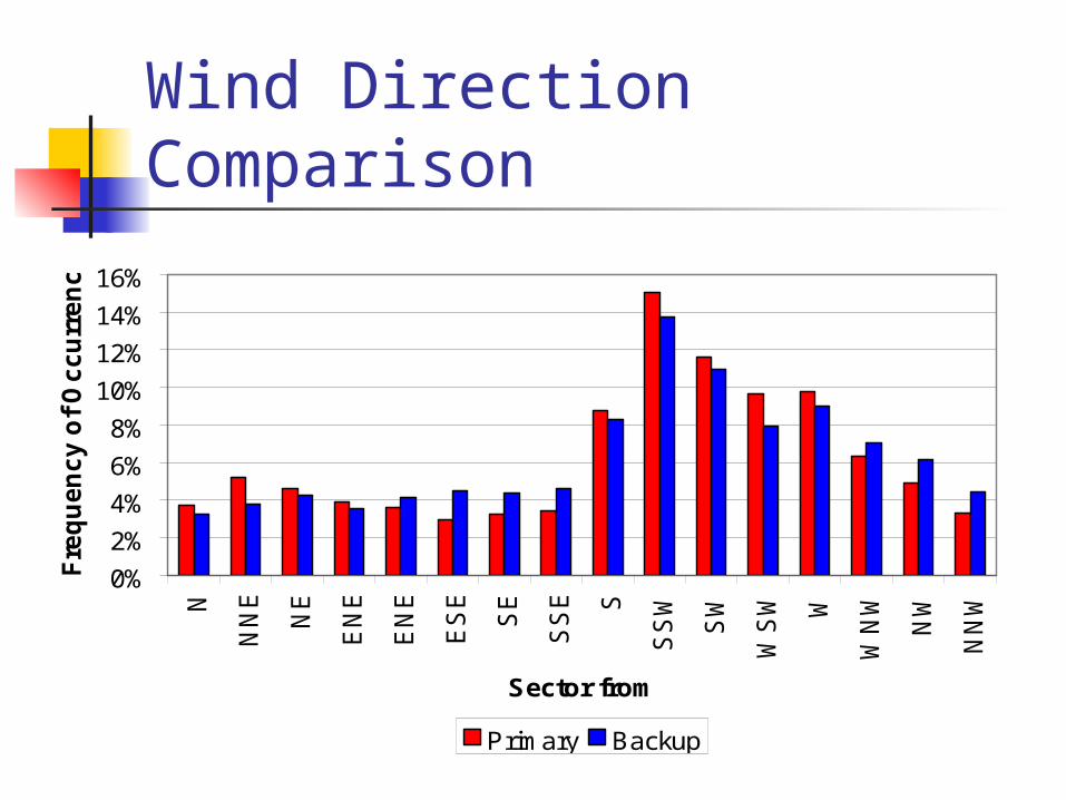
Wind Direction Comparison
0%
2%
4%
6%
8%
10%
12%
14%
16%
N
NNE
NE
ENE
ENE
ESE
SE
SSE S
SSW
SW
WSW W
WNW
NW
NNW
Sector from
Fre
qu
en
cy
of
Oc
cu
rre
nc
e
Primary Backup
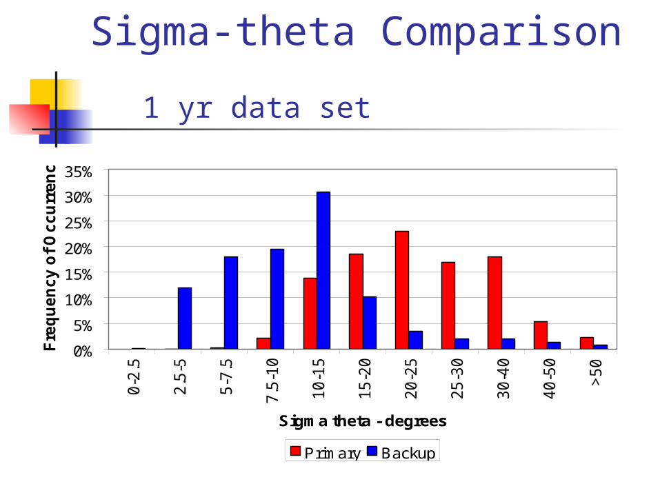
Sigma-theta Comparison 1 yr data set
0%
5%
10%
15%
20%
25%
30%
35%
0-2.5
2.5-5
5-7.5
7.5-10
10-15
15-20
20-25
25-30
30-40
40-50
>50
Sigma theta - degrees
Fre
qu
en
cy o
f O
ccu
rren
ce
Primary Backup

Stability Class ComparisonSigma-theta Method – 1 yr data set
0%
10%
20%
30%
40%
50%
60%
A B C D E F G
Stability Class
Fre
qu
en
cy
of
Oc
cu
rre
nce
Primary Backup

Stability Class ComparisonDelta-T Method – 10 yr data set
0%
5%
10%
15%
20%
25%
30%
35%
A B C D E F G
Stability Class
Fre
qu
en
cy o
f O
ccu
rren
ce
Primary Backup

Delta-T Stability Class Results were opposite of expected… Predicted backup tower, located near parking
lot with asphalt and cars, would shift stability toward unstable classes Expected asphalt and cars would result in 10-meter
temperature value biased in positive direction Since Delta-T = Upper-T minus Lower-T,
subtracting a larger 10-m temperature should bias Delta-T in negative direction
More negative Delta-T values should bias toward more unstable stability classes
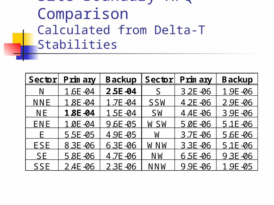
Site Boundary X/Q ComparisonCalculated from Delta-T Stabilities
Sector Primary Backup Sector Primary BackupN 1.6E-04 2.5E-04 S 3.2E-06 1.9E-06
NNE 1.8E-04 1.7E-04 SSW 4.2E-06 2.9E-06NE 1.8E-04 1.5E-04 SW 4.4E-06 3.9E-06ENE 1.0E-04 9.6E-05 WSW 5.0E-06 5.1E-06E 5.5E-05 4.9E-05 W 3.7E-06 5.6E-06
ESE 8.3E-06 6.3E-06 WNW 3.3E-06 5.1E-06SE 5.8E-06 4.7E-06 NW 6.5E-06 9.3E-06SSE 2.4E-06 2.3E-06 NNW 9.9E-06 1.9E-05

Site Boundary X/Q ComparisonCalculated from Delta-T Stabilities
1.E-06
1.E-05
1.E-04
1.E-031
23
4
5
6
78
910
11
12
13
14
1516
Primary Backup
0.E+00
1.E-04
2.E-04
3.E-041
23
4
5
6
78
910
11
12
13
14
1516
Primary Backup

Considerations Which tower is “best” for on-site
releases? Consider… Backup tower doesn’t meet ANSI/ANS
siting criteria Plant is surrounded by asphalt… like
backup tower – effect of delta-T, stability? Plant is on flat grade… like backup tower
– effect on wind profiles? Plant is near ocean… like backup tower

Considerations (continued)
Which level of instrumentation should be applied to on-site ground-level releases? Upper level of backup tower is at same
level as building vent. Convention is to apply 10-meter
meteorological measurements to ground-level and mixed-mode releases

Summary PNPS backup tower is typically discounted
because it does not meet ANSI/ANS siting criteria… site QA won’t accept it
However, backup tower is situated in an environment that more closely mimics the on-site ground-level release points
Use of backup tower meteorology yields a maximum site-boundary X/Q 39% HIGHER than that from the primary tower for ground-level releases
Summary (continued)
Questions for the experts… Is it always necessary, or
desirable, for a meteorological tower to meet ANSI/ANS siting criteria?
Should I use data from a tower that does not meet ANSI/ANS siting criteria?