Embed Size (px)
Citation preview
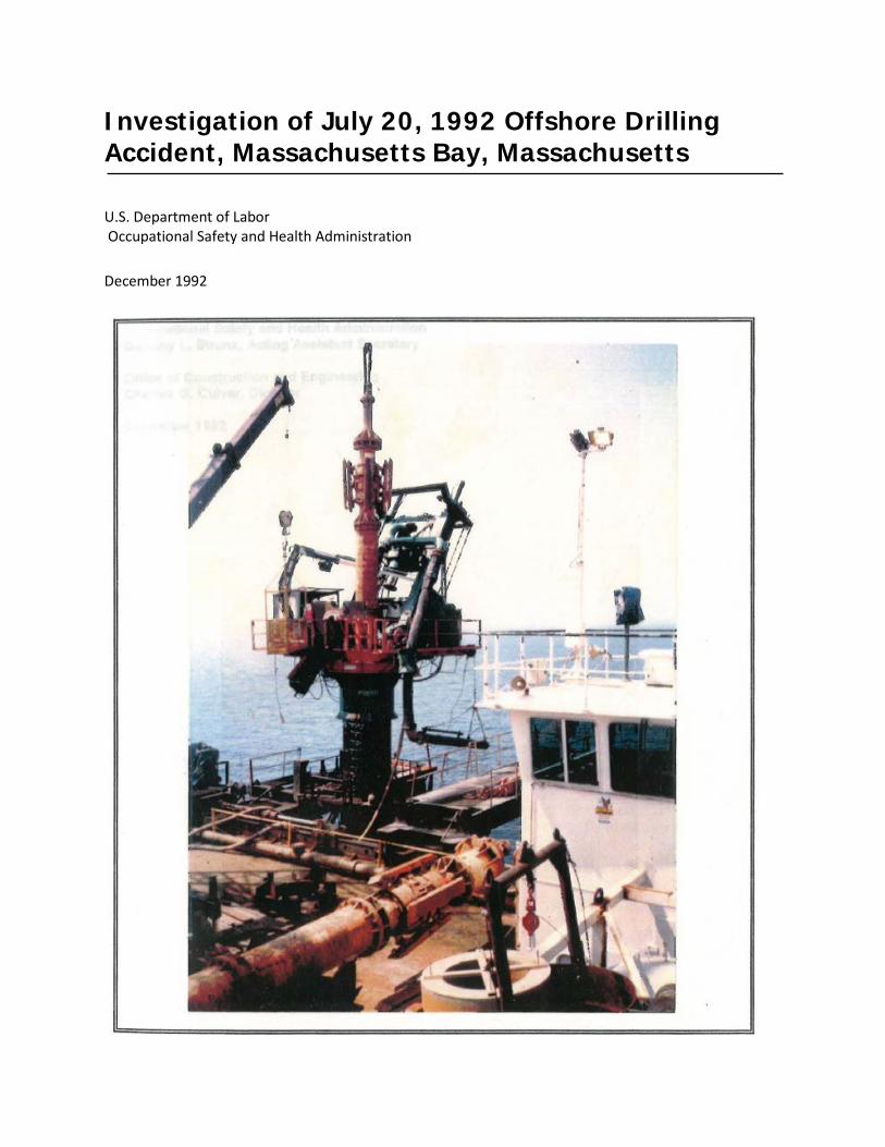
Investigation of July 20, 1992 Offshore Drilling Accident, Massachusetts Bay, Massachusetts U.S. Department of Labor Occupational Safety and Health Administration December 1992
Investigation of JUly 20, 1992 Offshore Drilling Accident, Massachusetts Bay, Massachusetts
u.s. Department of Labor Lynn Martin, Secretary
Occupational Safety and Health Administration Dorothy L. Strunk, Acting Assistant Secretary
Office of Construction and Engineering Charles G. Culver, Director
December 1992
Material contained In this publication Is In the public domain and may be reproduced, fully or partially, without permission of the Federal Government. Source credit Is requested but not required.
This report was written by:
J. Scott Jln
This Information will be made available to sensory Impaired Individuals upon requeat. Voice phone: (202) 219·8259 TOO message referral phone: 1·800·326·2577
)
TABLE OF CONTENTS )
EXECUTIVE SUMMARY ..................••....... . . . . .. v
1.0 INTRODUCTION "' 1
2.0 CONDUCT OF INVESTIGATION. . . . . . . . . . . . . . . . . . . . . . .. 5
) 3.0 DESCRIPTION OF THE OFFSHORE DRILLING PROCEDURE AND THE ACCIDENT. . . . . . . . . . . . . . • . . . . . . . . . . . . . . .. 7 3.1 Offshore Drilling Procedure ..........••......... 7 3.2 Description of the Accident . . . . . . . • • . . . . . . . . . . . .. 9
4.0 DISCUSSION AND CONCLUSIONS . . . . . . . . . . . . . . . . . . .. 23 4.1 Discussion................................. 23 4.2 Conclusion................................. 26
5.0 REFERENCES.................................... 32
APPENDIX A, GEOTECHNICAL EVALUATION AND CALCULATIONS 33
) APPENDIX B, SUMMARY OF LABORATORY TEST RESULTS 38
iv
I
I
EXECUTIVE SUMMARY
On July 20, 1992, at approximately 6:30 am, a 68 inch diameter, 206 feet long, steel pipe casing suddenly dropped vertically approximately 25 feet in about 2 seconds into the soft ocean sediment bed as the crane of the jack-up barge was releasing a 80 ton weight of the bottom hole assembly onto the platform of the drill unit, supported on top of the pipe casing. The accident occurred about nine miles offshore in the Massachusetts Bay during the construction of a sewage rehabilitation construction project, known as the Boston Harbor Cleanup Project. This vertical fall of the drill unit caused injuries to three employees working on the platform. One of them died during the next night at the Boston City Hospital.
Personnel from the Boston South Area Office of the Occupational Safety and Health Administration (OSHA), arrived at the scene within six hours after the accident. The Office of Construction and Engineering, OSHA, Washington, D.C., was requested to provide assistance in the technical assessment of the fallen drill unit and in determining the cause of the accident.
The OSHA investigation began soon after the accident and included interviewing witnesses, inspecting the drill unit and the hoist crane, reviewing the contract geotechnical and design documents, examining the Contractor's installation manual and associated records, and performing the geotechnical analysis and evaluation of the soil strata at the site. Based on the results of the investigation, OSHA concludes that:
1. The accident was caused by the drop of the steel pipe supporting casing into the soft ocean sediment layer when the casing, having penetrated through the five feet granular backfill, suddenly lost its bearing support. The sudden loss of the bearing support occurred when the dead load of the "bottom hole assembly" was imposed on the casing resulting in a total load in excess of the ultimate bearing capacity of the soft sediment. Subsequently, the platform doors of the drill unit were pushed upward by the wider flange of the bottom hole assembly. A worker was thrown up by the platform doors and fell half way into the top of the casing and later died. Two other workers standing on the fixed part of the platform, fell over each other, sustaining injuries.
2. This sudden and fast drop of the supporting casing with the drill unit could have been expected to occur, based on the geotechnical information available to the Contractor before the accident and the installation experience gained by him earlier in the project. In other words, the Contractor could have reasonably expected the supporting casing to penetrate through the entire
v
thickness of the soft sediment under the weight of the casing, the drill unit and the bottom hole assembly. In addition, the Contractor could have fully evaluated the impacts of the granulate backfill, a known factor, on the installation procedure.
3. It was an unsafe practice on the part of the Contractor to allow the employees to work on the drill platform, while the supporting casing was not adequately founded on the firm soil strata and a significant weight was being added onto the system.
)
vi
1.0 INTRODUCTION
On July 20, 1992, at approximately 6:30 am, a pile top drill unit and a 206 feet long pipe casing suddenly dropped vertically approximately 25 feet in about 2 seconds into the soft ocean sediment bed of the Massachusetts Bay as the crane of the jack-up barge was releasing a 80 ton bottom hole assembly onto the platform of the drill unit. This drill unit was on the last location of the contract, and the casing was installed over a 5 feet thick granular backfill which was placed due to a design change by the Construction Manager. This vertical fall of the drill unit caused injuries to three employees working on the platform. One of them was severely injured and died the next night at the Boston City Hospital.
The drilling unit, including the platform, was vertically supported by a 68-inch diameter steel casing, which was seated in the seabed. The steel casing was horizontally held above the sea level by the jack-up barge, which was supported on four legs, each 7.5 feet square in cross-section, embedded in the hard glacial till layer. Figures 1-1 through 1-3 present the relative locations of the jack-up barge and the drill unit. This operation took place, about 9.5 miles offshore in the Massachusetts Bay, for the installation of the underwater discharge points (riser-diffusers) for the treated sewage in the sewage rehabilitation construction project, known as the Boston Harbor Cleanup Project. The risers-diffusers were to be connected to the outfall tunnel from Deer Island.
Personnel from the Occupational Safety and Health Administration (OSHA), Boston South Area Office, were on the jack-up barge with the assistance of the Coast Guard within six hours of the accident, to conduct an on-site inspection, to interview employees, and to collect evidence in the form of photographs and videotapes. The Office of Construction and Engineering (OCE), National OSHA Office, Washington D.C., was subsequently requested, by OSHA Region I, to provide technical assistance to the Boston South Area Office in the investigation of the accident. Two engineers from the OCE, accompanied by a Safety Compliance Officer from the Boston South Area Office and an OSHA offshore drilling consultant visited the accident site on July 27, 1992 to inspect the drill unit, the hoist crane and the jack-up barge, to review the drilling procedures with the Contractor's engineering staff, and to collect the related records of the operation. In addition, the OCE held discussions with the Contractor's project manager and project engineer on July 29, 1992 regarding the engineering aspect of the operation.
The OSHA investigation included: (1) reviewing the geotechnical reports, contract plans and specifications of the project; (2) examining the Contractor's installation manual, drilling records and daily reports; (3) evaluating the witness statements; and (4) performing geotechnical analysis and computations for the bearing capacity of the soil strata under the seabed and for the depth of settlements of the supporting casing at different stages of the drilling operation.
1
)
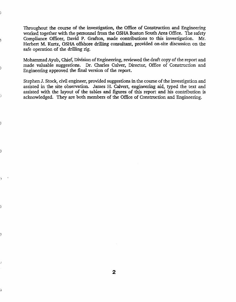
Throughout the course of the investigation, the Office of Construction and Engineering worked together with the personnel from the OSHA Boston South Area Office. The safety Compliance Officer, David P. Grafton, made contributions to this investigation. Mr. Herbert M. Kurtz, OSHA offshore drilling consultant, provided on-site discussion on the safe operation of the drilling rig.
Mohammad Ayub, Chief, Division of Engineering, reviewed the draft copy of the report and made valuable suggestions. Dr. Charles Culver, Director, Office of Construction and Engineering approved the final version of the report.
Stephen J. Stock, civil engineer, provided suggestions in the course of the investigation and assisted in the site observation. James H. Calvert, engineering aid, typed the text and assisted with the layout of the tables and figures of this report and his contribution is
) acknowledged. They are both members of the Office of Construction and Engineering.
)
)
2
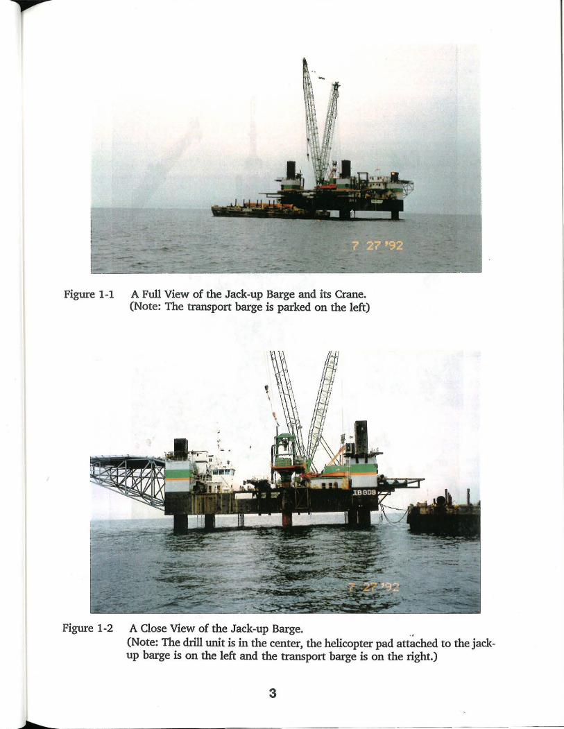
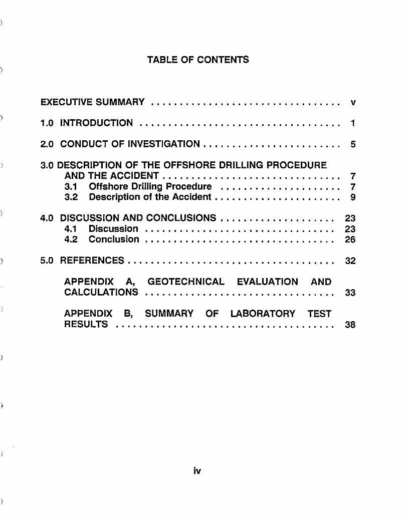
Figure 1-1 A Full View of the Jack-up Barge and its Crane. (Note: The transport barge is parked on the left)
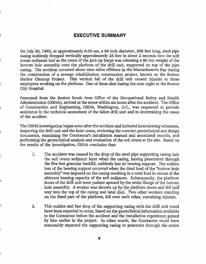
Figure 1-2 A Close View of the Jack-up Barge. .. (Note: The drill unit is in the center, the heUcopter pad attached to the jackup barge is on the left and the transport barge is on the right.)
3
I
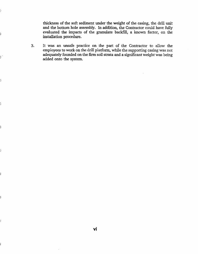
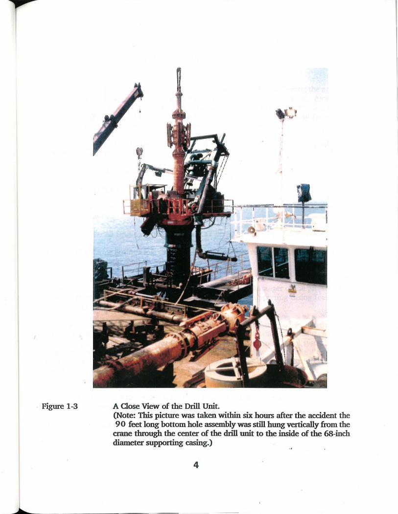
Figure 1-3 A Close View of the Drill Unit. (Note: This picture was taken within six hours after the accident the 9 0 feet long bottom hole assembly was still hung vertically from the crane through the center of the drill unit to the inside of the 68-inch diameter supporting casing.)
4

2.0 CONDUCT OF INVESTIGATION
As a result of the inspection by the OSHA Boston South Area Office following the accident, the Contractor submitted a Preliminary Accident Report, dated July 21, 1992. Along with this report, sketches were provided showing the various stages of the construction leading to the accident. The deck foreman's report, the emergency medical technician's report and three personal injury reports were also included in the package.
At the request of the OSHA Area Office, the Contractor transmitted the following documents on July 24, 1992:
o Compact Installation Manual (1992), prepared by the Contractor.
o Jack-up log for period 7/15/92 through 7/23/92.
o Elevated Condition Limits for Jack-up Barge (1991), prepared by Marine Structure Consultants.
o 1988 Marine Drilling Summary Report (1989), prepared by Metcalf & Eddy.
o 1989 Marine Boring Program, Geotechnical Interpretive Report (1990), prepared by Parsons Brinckerhoff Quade & Douglas, Inc.
About the same date, the OSHA Area Office was also provided with a copy of the ROV (remotely operated vehicles) video tape by the Construction Manager of the project. This tape recorded the survey of the seabed surface outside the supporting casing (casing A), approximately 9 hours after the accident.
On July 27, 1992, two engineers from the OSHA Office of Construction and Engineering, an OSHA offshore drilling consultant and a Safety Compliance Officer, visited the accident site. The purpose of this visit was to inspect the mechanical and control systems of the drill unit and the hoist crane, to review the drilling procedures with the Contractor's engineering staff to inspect the jack-up barge, and to collect the related records of the operation. Subsequent to this visit, the contractor submitted the following records and documents on July 28, 1992.
o Complete set of field records for Riser Nos. 55, 28, and 2, each with a checklist of the temporary casing A. (Form IILA.6)
o Field record for Riser No.1 (the accident hole) as completed up to 7/27/92, with a checklist of the temporary casing A. (Form IILA.6)
5
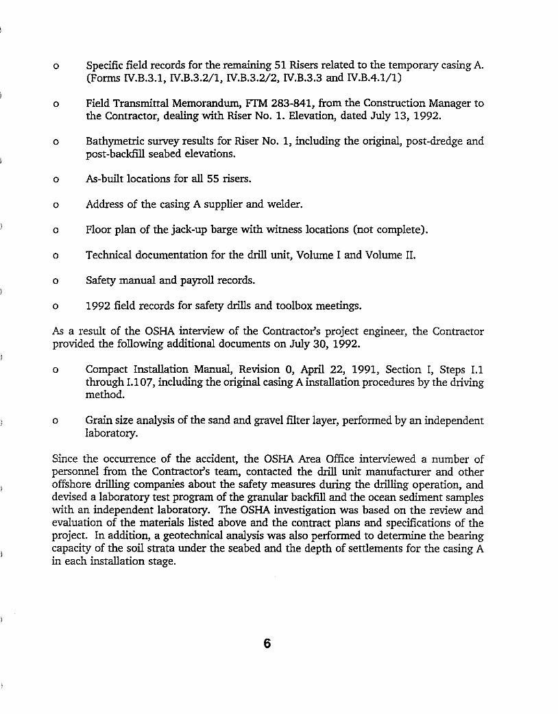
o Specific field records for the remaining 51 Risers related to the temporary casing A. (Forms IV.B.3.1, IV.B.3.2/1, IV.B.3.2/2, IV.B.3.3 and IV.BA.l/1)
o Field Transmittal Memorandum, FTM 283-841, from the Construction Manager to the Contractor, dealing with Riser No. 1. Elevation, dated July 13, 1992.
o Bathymetric survey results for Riser No.1, including the original, post-dredge and post-backfill seabed elevations.
o As-built locations for all 55 risers.
o Address of the casing A supplier and welder.
o Floor plan of the jack-up barge with witness locations (not complete).
o Technical documentation for the drill unit, Volume I and Volume II.
o Safety manual and payroll records.
o 1992 field records for safety drills and toolbox meetings.
As a result of the OSHA interview of the Contractor's project engineer, the Contractor provided the following additional documents on July 30, 1992.
o Compact Installation Manual, Revision 0, April 22, 1991, Section I, Steps I.1 through 1.107, including the original casing A installation procedures by the driving method.
o Grain size analysis of the sand and gravel filter layer, performed by an independent laboratory.
Since the occurrence of the accident, the OSHA Area Office interviewed a number of personnel from the Contractor's team, contacted the drill unit manufacturer and other offshore drilling companies about the safety measures during the drilling operation, and devised a laboratory test program of the granular backfill and the ocean sediment samples with an independent laboratory. The OSHA investigation was based on the review and evaluation of the materials listed above and the contract plans and specifications of the project. In addition, a geotechnical analysis was also performed to determine the bearing capacity of the soil strata under the seabed and the depth of settlements for the casing A in each installation stage.
6
3.0 DESCRIPTION OF THE OFFSHORE DRILLING PROCEDURE AND THE ACCIDENT
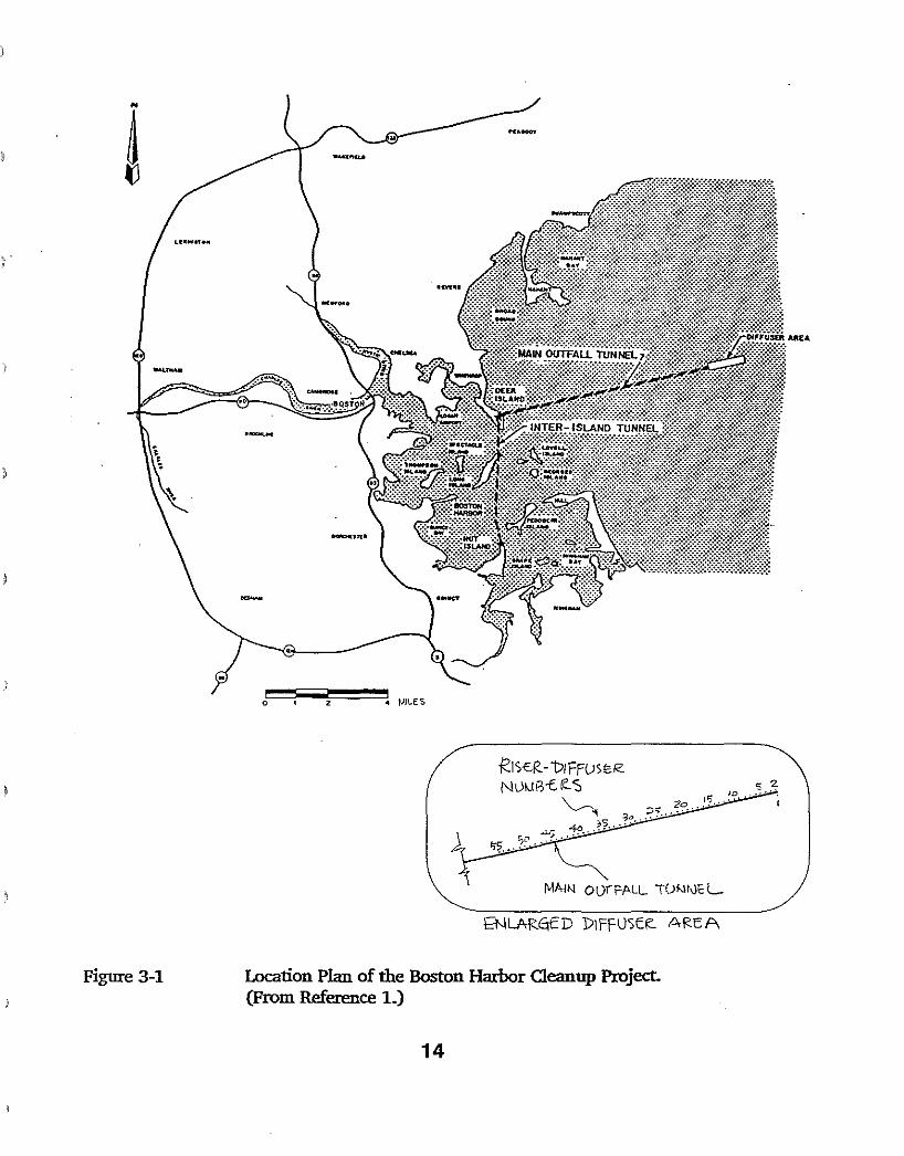
The Effluent Outfall Diffusers Project, Contract Package 283, undertakes the installation of 55 Riser-Diffusers as a part of a much larger construction project called the Boston Harbor Cleanup Project. This $6 billion project, under the Massachusetts Water Resources Authority, includes the construction of a sewage treatment facilities on Deer Island, a new headworks facility on Nut Island, a tunnel and shafts connecting the Nut Island facilities to the Deer Island treatment plant, and a shaft, a 10 mile long outfall tunnel, and a diffuser system which will discharge the treated sewage into the Massachusetts Bay. (See Figure
) 3-1)
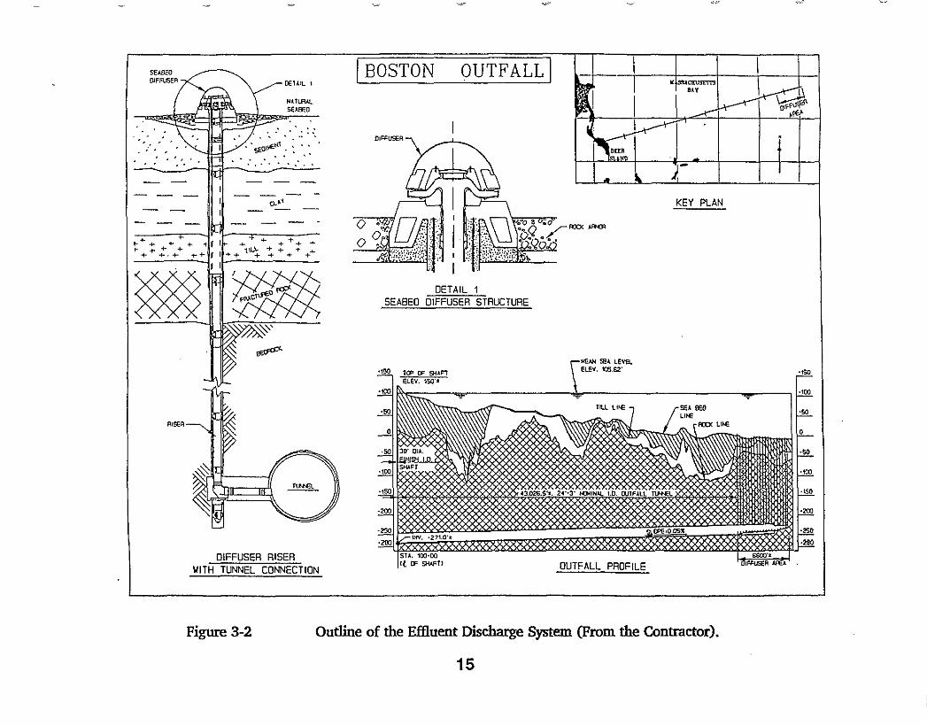
The effluent discharge takes place over the last 6600 feet of the 10 miles long tunnel through the 55 fiberglass reinforced plastic (FRP) pipe risers. Each FRP riser consisting of a 30 inch diameter pipe with 1.75 inches wall thickness and 250 feet length was lowered and grouted in a predrilled shaft in the seabed. Each riser is capped with a diffuser consisting of a concrete base latched onto a 50 feet long, 58 inches diameter, and 1.5 inches wall thickness permanent steel casing, grouted to the bedrock, an 8 ports FRP manifold cast into concrete, a concrete ringwall and a high density polyethylene protective dome. (See Figure 3-2). A generalized geological profile from the Deer Island shaft to the end of diffuser area is also presented in the figure. Note that the selection of the diffuser installation procedure and the design of all special equipment and temporary work items for the selected procedures were done at the discretion of the Contractor of the Effluent Outfall Diffusers Project, CP-283.
Based on the Compact Installation Manual provided by the Contractor, there were 24 major steps (phases) to install a riser-diffuser unit. However, only the first three steps and other related activities are described in the following section, as they pertain to this investigation.
3.1 Offshore Drilling Procedure
The procedures for the installation of the diffusers are outlined as follows:
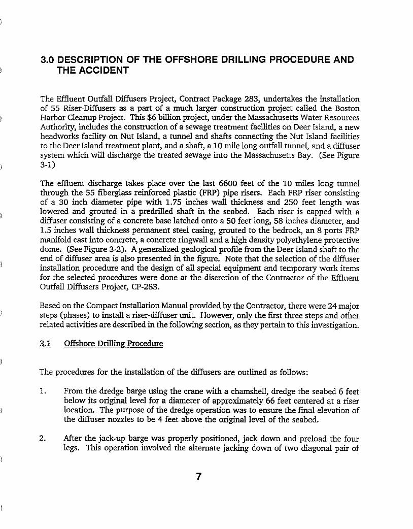
1. From the dredge barge using the crane with a chamshell, dredge the seabed 6 feet below its original level for a diameter of approximately 66 feet centered at a riser location. The purpose of the dredge operation was to ensure the final elevation of the diffuser nozzles to be 4 feet above the original level of the seabed.
2. After the jack-up barge was properly positioned, jack down and preload the four legs. This operation involved the alternate jacking down of two diagonal pair of
7
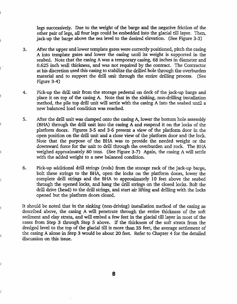
legs successively. Due to the weight of the barge and the negative friction of the other pair oflegs, all four legs could be embedded into the glacial till layer. Then, jack-up the barge above the sea level to the desired elevation. (See Figure 3-3)
3. After the upper and lower template gates were correctly positioned, pitch the casing A into template gates and lower the casing until its weight is supported in the seabed. Note that the casing A was a temporary casing, 68 inches in diameter and 0.625 inch wall thickness, and was not required by the contract. The Contractor at his discretion used this casing to stabilize the drilled hole through the overburden material and to support the drill unit through the entire drilling process. (See Figure 3-4)
4. Pick-up the drill unit from the storage pedestal on deck of the jack-up barge and place it on top of the casing A. Note that in the sinking, non-drilling installation method, the pile top drill unit will settle with the casing A into the seabed until a new balanced load condition was reached.
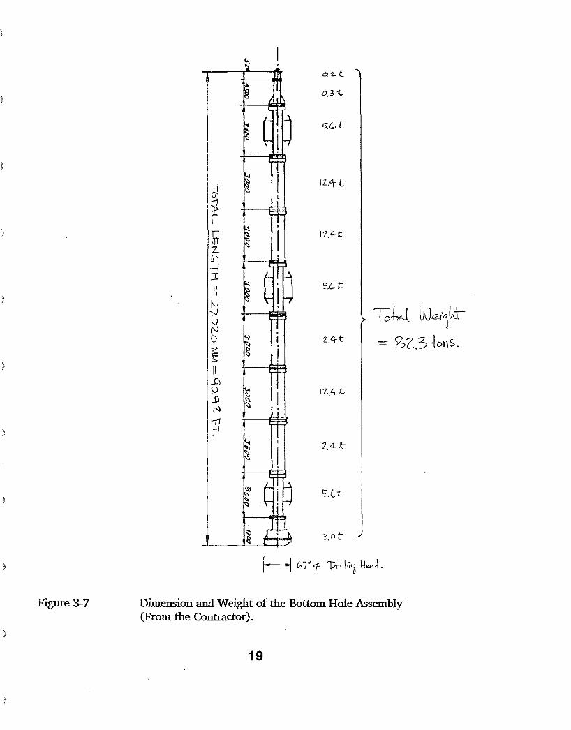
5. After the drill unit was clamped onto the casing A, lower the bottom hole assembly (BHA) through the drill unit into the casing A and suspend it on the locks of the platform doors. Figures 3-5 and 3-6 present a view of the platform door in the open position on the drill unit and a close view of the platform door and the lock. Note that the purpose of the BHA was to provide the needed weight or the downward force for the unit to drill through the overburden and rock. The BHA weighed approximately 80 tons. (See Figure 3-7) Again, the casing A will settle with the added weight to a new balanced condition.
6. Pick-up additional drill strings (rods) from the storage rack of the jack-up barge, bolt these strings to the BHA, open the locks on the platform doors, lower the complete drill strings and the BHA to approximately 10 feet above the seabed through the opened locks, and hang the drill strings on the closed locks. Bolt the drill drive (head) to the drill strings, and start air lifting and drilling with the locks opened but the platform doors closed.
It should be noted that in the sinking (non-driving) installation method of the casing as described above, the casing A will penetrate through the entire thickness of the soft sediment and clay strata, and will embed a few feet in the glacial till layer in most of the cases from Step 3 through Step 5 above. If the thickness of the soft strata from the dredged level to the top of the glacial till is more than 35 feet, the average settlement of the casing A alone in Step 3 would be about 20 feet. Refer to Chapter 4 for the detailed discussion on this issue.
8
3.2 Description of the Accident
The day after the accident, the contractor submitted a preliminary accident report, which included the details of the installation procedures leading to the accident and a brief description of the accident. Based on this preliminary report, the witness accounts (See Table 3-1), our review of the provided documents, and our evaluation and assessment of the operation, the accident could be described as follows. Note that the accident occurred in Step 5 of Section 3.1, when the 80 tons BHA was being suspended on the locks of the platform doors.
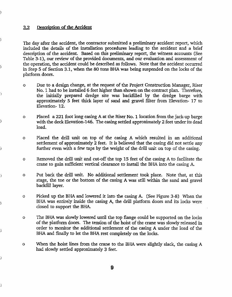
o Due to a design change, at the request of the Project Construction Manager, Riser No. 1 had to be installed 6 feet higher than shown on the conttact plan. Therefore,
) the initially prepared dredge site was backfilled by the dredge barge with approximately 5 feet thick layer of sand and gravel filter from Elevation- 17 to Elevation- 12.
o Placed a 221 foot long casing A at the Riser No.1 location from the jack-up barge with the deck Elevation-I46. The casing settled approximately 2 feet under its dead load.
o Placed the drill unit on top of the casing A which resulted in an additional settlement of approximately 2 feet. It is believed that the casing did not settle any further even with a few taps by the weight of the drill unit on top of the casing.
o Removed the drill unit and cut-off the top 15 feet of the casing A to facilitate the crane to gain sufficient vertical clearance to install the BHA into the casing A.
o Put back the drill unit. No additional settlement took place. Note that, at this stage, the toe or the bottom of the casing A was still within the sand and gravel backfill layer.
o Picked up the BHA and lowered it into the casing A. (See Figure 3-8) When the BHA was entirely inside the casing A, the drill platform doors and its locks were closed to support the BHA.
o The BHA was slowly lowered until the top flange could be supported on the locks of the platform doors. The tension of the hoist of the crane was slowly released in order to monitor the additional settlement of the casing A under the load of the BHA and finally to let the BHA rest completely on the locks.
o When the hoist lines from the crane to the BHA were slightly slack, the casing A had slowly settled approximately 3 feet.
9
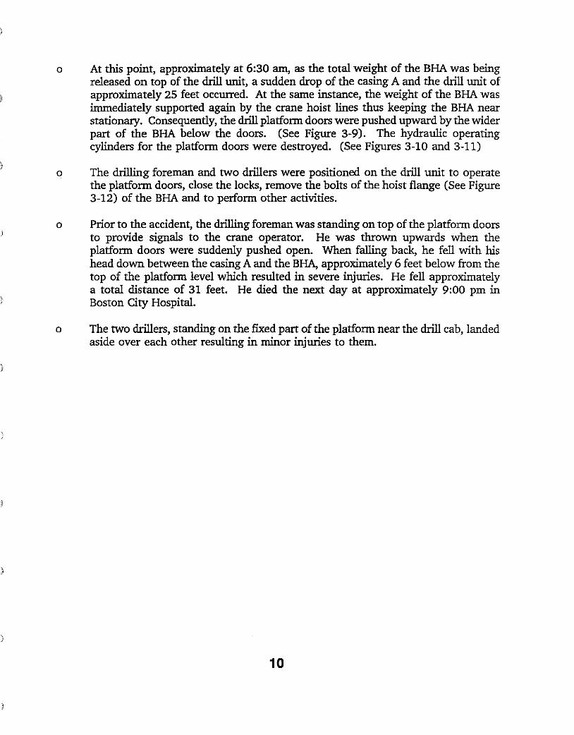
o At this point, approximately at 6:30 am, as the total weight of the BHA was being released on top of the drill unit, a sudden drop of the casing A and the drill unit of approximately 25 feet occurred. At the same instance, the weight of the BHA was immediately supported again by the crane hoist lines thus keeping the BHA near stationary. Consequently, the drill platfonn doors were pushed upward by the wider part of the BHA below the doors. (See Figure 3-9). The hydraulic operating cylinders for the platfonn doors were destroyed. (See Figures 3-10 and 3-11)
o The drilling foreman and two drillers were positioned on the drill unit to operate the platfonn doors, close the locks, remove the bolts of the hoist flange (See Figure 3-12) of the BHA and to perfonn other activities.
o Prior to the accident, the drilling foreman was standing on top of the platfonn doors to provide signals to the crane operator. He was thrown upwards when the platfonn doors were suddenly pushed open. When falling back, he fell with his head down between the casing A and the BHA, approximately 6 feet below from the top of the platfonn level which resulted in severe injuries. He fell approximately a total distance of 31 feet. He died the next day at approximately 9:00 pm in Boston City Hospital.
o The two drillers, standing on the fixed part of the platfonn near the drill cab, landed aside over each other resulting in minor injuries to them.
10
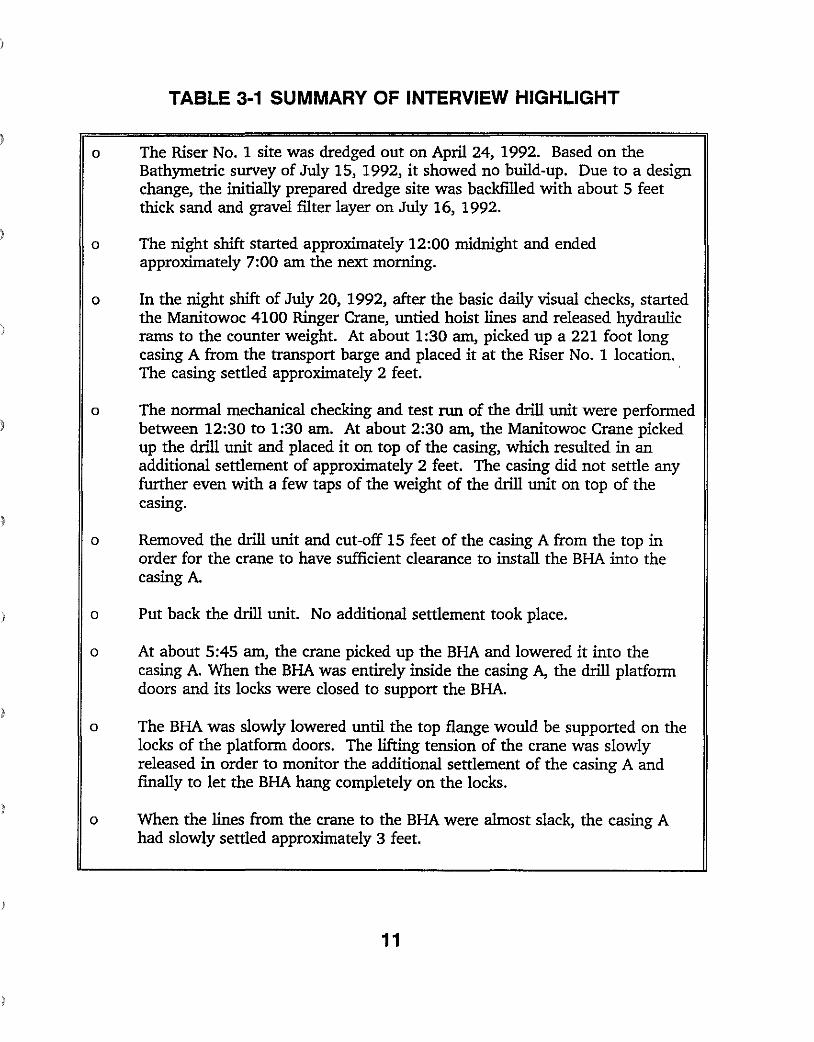
TABLE 3·1 SUMMARY OF INTERVIEW HIGHLIGHT
o The Riser No. 1 site was dredged out on April 24, 1992. Based on the Bathymetric survey of July 15, 1992, it showed no build-up. Due to a design change, the initially prepared dredge site was backfilled with about 5 feet thick sand and gravel filter layer on July 16, 1992.
o The night shift started approximately 12:00 midnight and ended approximately 7:00 am the next morning.
o In the night shift of July 20, 1992, after the basic daily visual checks, started the Manitowoc 4100 Ringer Crane, untied hoist lines and released hydraulic rams to the counter weight. At about 1:30 am, picked up a 221 foot long casing A from the transport barge and placed it at the Riser No. 1 location. The casing settled approximately 2 feet.
o The normal mechanical checking and test run of the drill unit were performed between 12:30 to 1:30 am. At about 2:30 am, the Manitowoc Crane picked up the drill unit and placed it on top of the casing, which resulted in an additional settlement of approximately 2 feet. The casing did not settle any further even with a few taps of the weight of the drill unit on top of the casing.
o Removed the drill unit and cut-off 15 feet of the casing A from the top in order for the crane to have sufficient clearance to install the BHA into the casing A.
o Put back the drill unit. No additional settlement took place. !
o At about 5:45 am, the crane picked up the BHA and lowered it into the casing A. When the BHA was entirely inside the casing A, the drill platform doors and its locks were closed to support the BHA.
o The BHA was slowly lowered until the top flange would be supported on the locks of the platform doors. The lifting tension of the crane was slowly released in order to monitor the additional settlement of the casing A and finally to let the BHA hang completely on the locks.
o When the lines from the crane to the BHA were almost slack, the casing A had slowly settled approximately 3 feet.
11
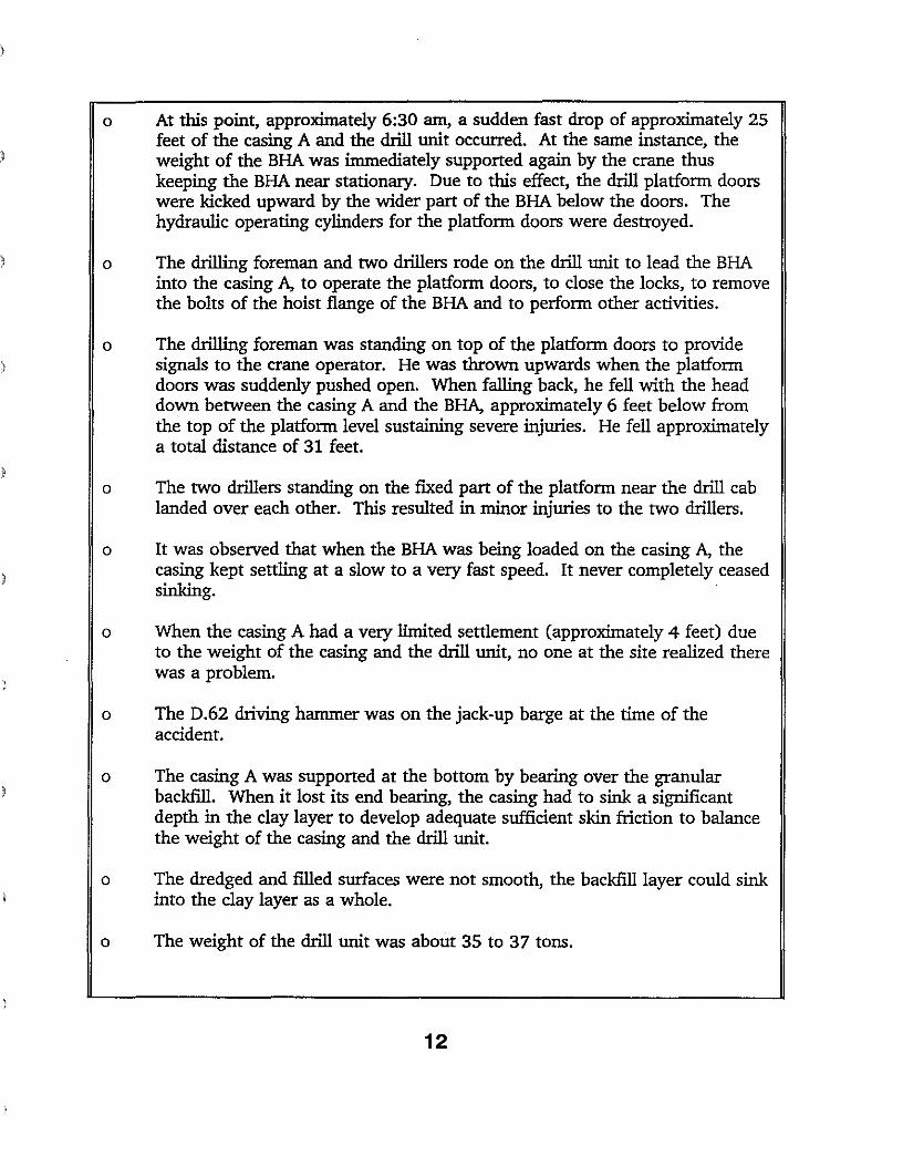
o At this point, approximately 6:30 am, a sudden fast drop of approximately 25 feet of the casing A and the drill unit occurred. At the same instance, the weight of the BHA was immediately supported again by the crane thus keeping the BHA near stationary. Due to this effect, the drill platform doors were kicked upward by the wider part of the BHA below the doors. The hydraulic operating cylinders for the platform doors were destroyed.
o The drilling foreman and two drillers rode on the drill unit to lead the BHA into the casing A, to operate the platform doors, to close the locks, to remove the bolts of the hoist flange of the BHA and to perform other activities.
o The drilling foreman was standing on top of the platform doors to provide signals to the crane operator. He was thrown upwards when the platform doors was suddenly pushed open. When falling back, he fell with the head down between the casing A and the BHA, approximately 6 feet below from the top of the platform level sustaining severe injuries. He fell approximately a total distance of 31 feet.
)
o The two drillers standing on the fixed part of the platform near the drill cab landed over each other. This resulted in minor injuries to the two drillers.
o It was observed that when the BHA was being loaded on the casing A, the casing kept settling at a slow to a very fast speed. It never completely ceased sinking.
o When the casing A had a very limited settlement (approximately 4 feet) due to the weight of the casing and the drill unit, no one at the site realized there was a problem.
o The D.62 driving hammer was on the jack-up barge at the time of the accident.
o The casing A was supported at the bottom by bearing over the granular backfill. When it lost its end bearing, the casing had to sink a significant depth in the clay layer to develop adequate sufficient skin friction to balance the weight of the casing and the drill unit.
o The dredged and filled surfaces were not smooth, the backfill layer could sink into the clay layer as a whole.
o The weight of the drill unit was about 35 to 37 tons.
12
)
o There were nonnally 3 to 4 employees stationed on the drill unit, while it was hoisted to or removed from the casing A.
o After the accident, the Contractor did not experience any difficulties in drilling on Riser No.1, because of sand and gravel.
o The emergency medical technician (EMT) worked on the 10:00 pm to 10:00 am shift, he/she also acted as a flight controller for the helicopter.
)
13
o z .. Mll..ES
1<:IS£R.- "DIFFUSei<C N0fJfl-e re. ~
~, .~'?.
!'IAIN OOfFAlL T()IJI0l: L
Figure 3-1 Location Plan of the Boston Harbor Cleanup Project. (From Reference 1.)
14
·,so
·100
.,.
~ O\FF~ .t<J'
~AH se.l. LEva REV. -'(5,62'-150 t()'> OF SHAFT
ELE.... 150'1;
'1001 Rtt=:r:::: """!P ~ "!!"'"
·so AlSEA
o
·so
'100
·200
'150
~
.""(PE,o.osx
OUTFALL PROFILE
43.02G.5'!.24·'3' /'OIrN.IJ.. 1.0. OJTF.l,LL T1..N'EL·,so
·200
~ m.... -271.0'" .",
SUo 100-00 It a= SHAFTl
D1FFI,JSER RISER \11TH TI,JNNEL CONNECTION
~'
*"'*
oeUIL I
,#JlFl.IJ..
"""' : 1M './ .. :.' :: ~ ··'EJE.O\~~'.: '.:'
- ....
(1.'<
t-+-+--+--t,I4- ++++ ~ I r. "+ + t- + + + ,IL\' + ... ... .... -+- -+- + , I ...... ... ++
~" ~
IBOSTON OUTFALL I
Dll+lJSEA
."0 ,"I":. '.'.. ;J '. QU"d """ ".'"tH!:: P'rlC:'.1 ':,\i/i.O'l;'~· 0
KEY PLAN
DETAIL 1 SEABED DIFFUSER STRUCTURE
Figure 3-2 Outline of the Effluent Discharge System (From the Contractor).
15
I

-=:'==--==--~_=-=-=-==-=-=-=--4L_=_---=~+;:--+---r+--:---~+:'-- -"5'5- CoS + +1'J?ACiUI<&D eocK.+ + ++ +
-110 + +
RoPE SO~PE:IJPGD lEAvE;!<. N\T~ D~'1.
HAMM'e\<..
'RA"'P<>r.T UR6E FOr. C)\S1"'G p.
Iv\AN\TOWOC 4100 S'S e'No, \:;R.. CQA~E,
IgoPr &>oM.
TA(J:: -\)P BAt<G E
~~m·~
J,iI<I:-up MR..", ANUIOI'. L"oE CASINO. A
-'2
1--+----'=-- -"5
..
MA'I<IMUIJ
":£;l\<lf;V pC~TIDt--I d C4SlrJG.t A
-2<:;'oF., "1Ot>1~IE!", i cJ.P'f
-2';
) TIL-L- -- - -
Figure 3-3 Elevation of the Jack-up Barge and the Casing A (From the Contractor)
16
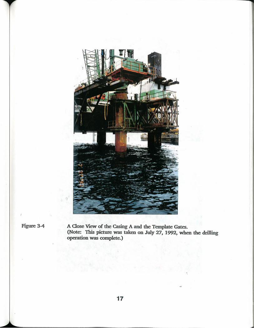
Figure 3-4 A Close View of the Casing A and the Template Gates. (Note: This picture was taken on July 27, 1992, when the drilling operation was complete.)
•,
17
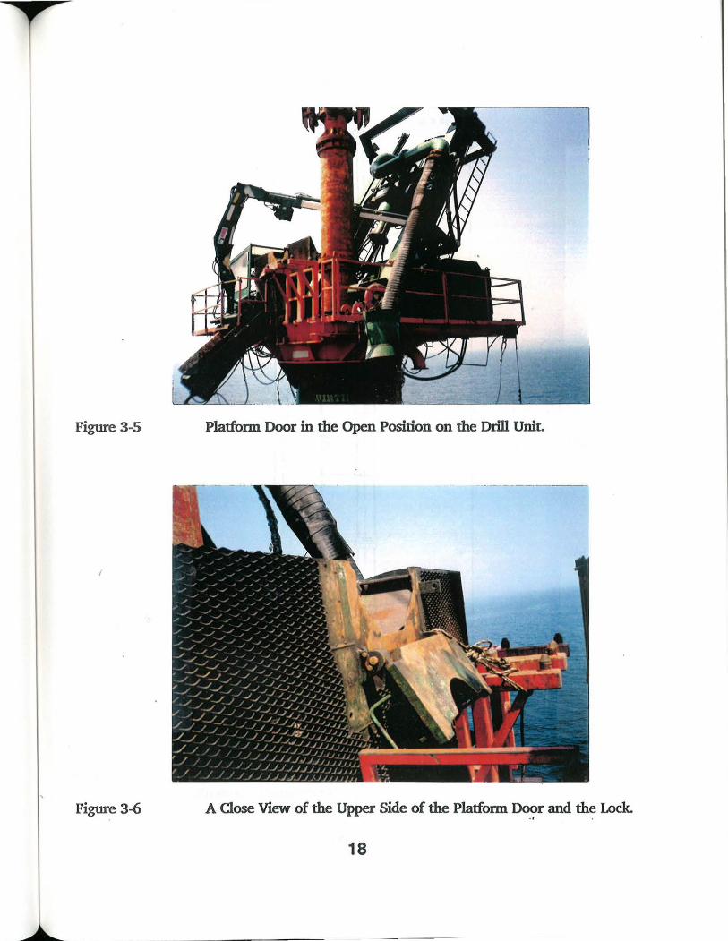
Figure 3-5 Platform Door in the Open Position on the Drill Unit.
Figure 3-6 A Close View of the Upper Side of the Platform Door and the Lock. • • 0
18
I I I ! [-I10'
!:i1 r
) Irr z. fi' -I J:
II IV -"J -J ('J 0 s: ~
II J:\ 9 .1l f"\ -r1 -I
,~
~ ,
Ff
1-'f ,~ l 1:-;
n= ~ I
1
~ I ...L
~.J .-1
,
~ L:
rr I~
l; I,
Fr ~ I~ i
if, ~ I
~~~ tu :J=~~ f
6,3t
12.'\- t
1'2.4t:
124t
17..41:
1),(, t
3.0t
~w WeiJW:= SZ,3 +Ons.
Figure 3-7 Dimension and Weight of the Bottom Hole Assembly (From the Contractor).
19
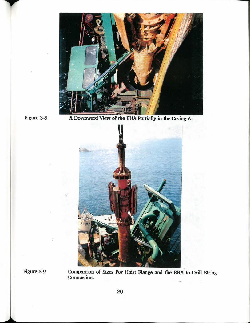
Figure 3-8
I
Figure 3-9
A Downward View of the BHA Partially in the Casing A
Comparison of Sizes For Hoist Flange and the BHA' to Drill String Connection.
20
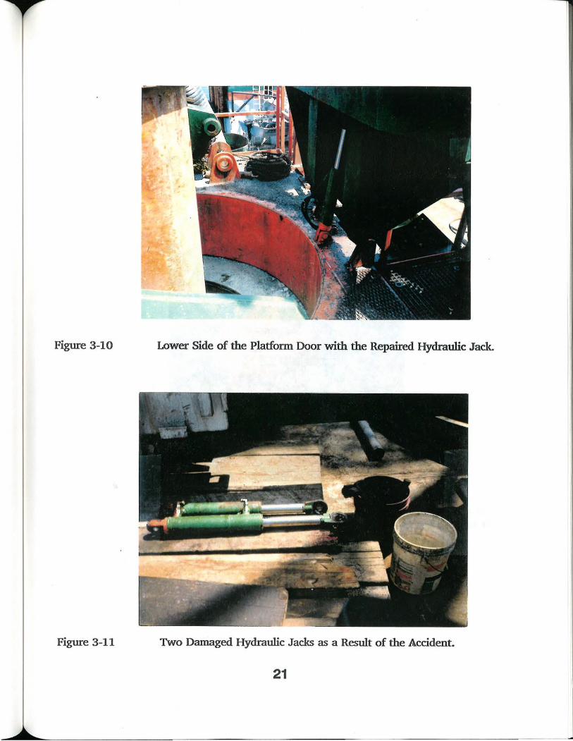
Figure 3-10 Lower Side of the Platform Door with the Repaired Hydraulic Jack.
Figure 3-11 Two Damaged Hydraulic Jacks as a Result of the Accident.
21
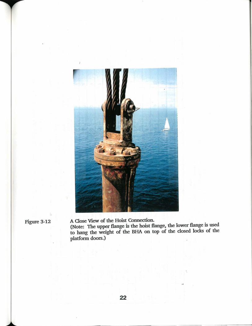
Figure 3-12 A Close View of the Hoist Connection. (Note: The upper flange is the hoist flange, the lower flange is used to hang the weight of the BHA on top of the closed locks of the platform doors.)
22
4.0 DISCUSSION AND CONCLUSIONS
4.1 Discussion
Based on the OSHA initial inspection of July 20, 1992, within 6 hours of the accident, it was detennined that there was no failure of any gear or equipment which might have led to the sudden drop of the supporting casing. During the July 27, 1992 visit to the jack-up barge by three OSHA officials and an OSHA offshore drilling consultant, the mechanical and control systems of both the drill unit and hoist crane were examined. Besides, the crane successfully supported the 80 tons BHA during the accident and held this load for several hours. In fact, after the accident, both equipments completed the installation of the Riser No. 1 without any difficulties. Therefore, the OSHA investigation concentrated on the drilling procedure and the geotechnical consideration of the soil encountered at the seabed.
Based on the review of the ROV video tape, the seabed surface outside the casing A appeared relatively flat and level subsequent to the accident. There were no sink holes. However, a two feet wide sloped surface around and toward the casing was observed. The angle of this slope was approximately 45 degrees, thus, the maximum surface settlement adjacent to the casing was about 2 feet. The type of the material exposed on the seabed near the casing was angular sand and gravel, with some rocks sized up to 6 inches. Based on this tape, it is believed that there were no significant pre-existing large voids or other geotechnical anomaly.
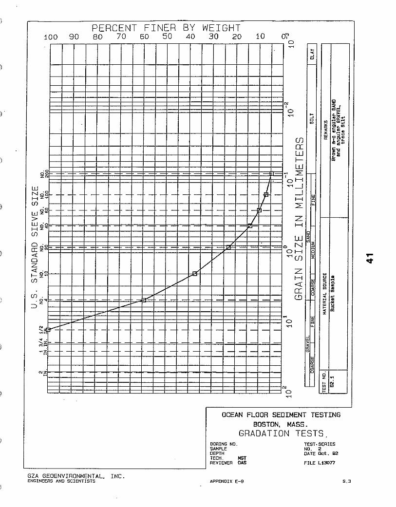
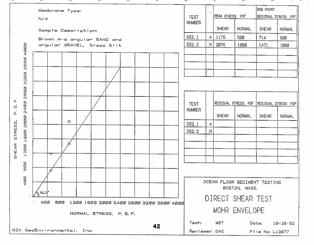
Laboratory tests were performed on the two samples submitted by the Contractor. The test results are included in Appendix B. Sieve analysis and direct shear tests were conducted on the sand and gravel backfill (bucket sample). The gradation of this sample conformed to the contract requirement as a sand and gravel filter layer. However, a high friction angle of 56 degrees indicated a relatively high angularity of constituents. Natural water contents, Atterberg limits and torvane tests were performed on a 12 inches diameter, 2 to 4 inches thick block sample. Based on the natural water content and the gradation, this sample appeared coming from the lower level clay layer near the top of the till, rather than the upper level soft sediment. The above information was considered in the evaluation of the bearing capacity.
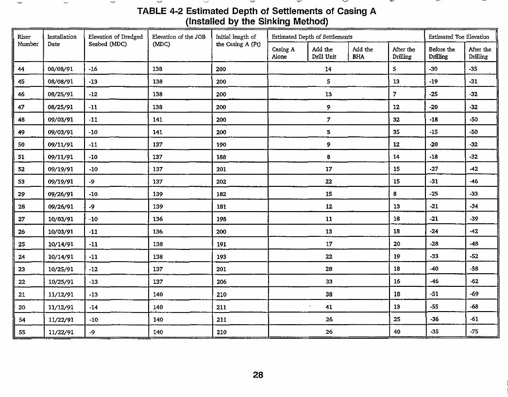
The settlement or sinking depth of the temporary casing A is tabulated, based on the Forms IV.B.3.1, IV.B.3.2/1, IV.B.3.2/2, IV.B.3.3 and IV.BA.1/1, or similar forms used in an earlier stage of the project. The purpose of this effort is to correlate the depth of the settlement at various installation stages with the type of soil strata encountered. This information is presented in Tables 4-1 through 4-3. The sequence of presentation is based on the date of installation for each riser. Due to the change in the installation procedures by the
23
Contractor from driving to sinking, and the modification of the forms, the format of Tables 4-1 through 4-3 is also adjusted accordingly. Note that in these tables, if the direct record of the dredged seabed elevation is not available, this elevation is assumed to be either 6 feet below the natural seabed or 7 feet below the top of the permanent casing.
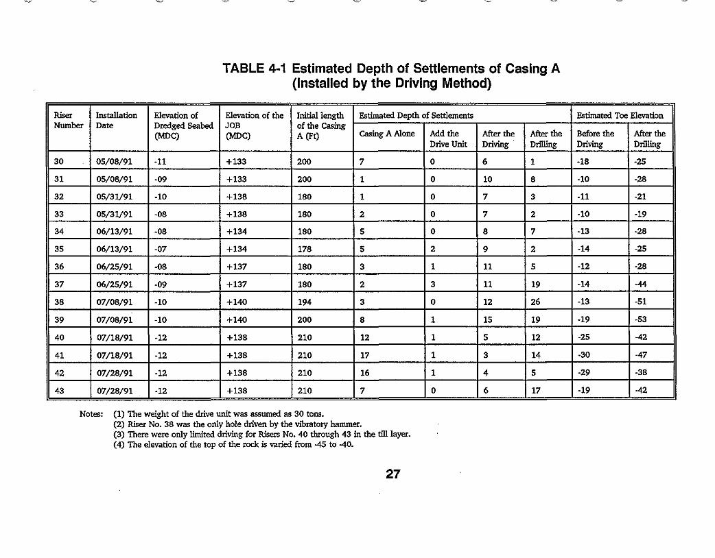
Based on the review of the casing A installation records as listed above, the first 14 casing were installed by the driving method. They were Risers No. 30 through 43, and tabulated in Table 4-1. From this table, only one casing at Riser No. 38 was driven by the vibratory method, the remaining 13 casing were installed by the D.62 diesel hanuner. From the comparison of the casing toe elevation before driving and the corresponding Geological Profile (Reference 2), most of the casings were set on top of the glacial till layer prior to the driving operation.
In other words, the Contractor gained all his experience by driving casing A through a relatively hard and boulderous glacial till layer. Upon further examining Table A-I, it was observed that the first 7 casings would definitely have sustained damage to the casing A. It was due to the fact that the toe of the casings could not reach the top of the rock as intended and the associated lengthy installation time. For the remaining 7 casings, no such problems were identified. This was probably due to the assistance provided by the casing driving shore and a limited driving of the casing A in the till layer. Therefore, there were no sufficient records to demonstrate that a limited driving would cause the damage of the casing A, particularly in the upper soft sediment and clay strata.
Table 4-2 presents the next 22 casings installed before the winter of 1991 by the sinking method. There were no separate records of the settlement depths for the casing A alone or the casing A with the drill unit. However, the available records showed that, in most of the cases, the toe of the casing A penetrated through the entire thickness of the soft sediment and clay layer with the combined weight of the casing, the drill unit and the
) bottom hole assembly (BHA). The combined weight of this system was approximately 160 tons. The skin friction of the soft sediment and clay layer was not adequate to support this system, and as a result the end bearing of the casing A was placed at the bottom of this layer or in the glacial till layer to balance the entire weight of the system. Therefore, the depth of the settlement for the combined system was dependent on the thickness of the soft sediment and clay layer. In addition, the toe of the casing after the drilling operation was advanced to within 5 feet of the top of the rock, as expected.
The installation records for the last 19 casing, including the one involved with the accident are presented in Table 4-3. They were installed since the Spring of 1992. In this table, the same trends were observed as in Table 4-2. However, since a separate record of the casing settlements in each stage was kept, additional correlations could be made. The average thickness of the soft sediment and clay layer was 35.8 feet and the average depth of settlement for the casing A alone weighing approximately 54 tons, was 20.2 feet for Risers No.2 through 19. An estimated cohesion of this layer could be obtained through back analysis. This information is very valuable for the estimation of the bearing capacity
24
of the soft sediment below the granular backfill prior to the accident. The detail of this estimation is presented in the Appendix A.
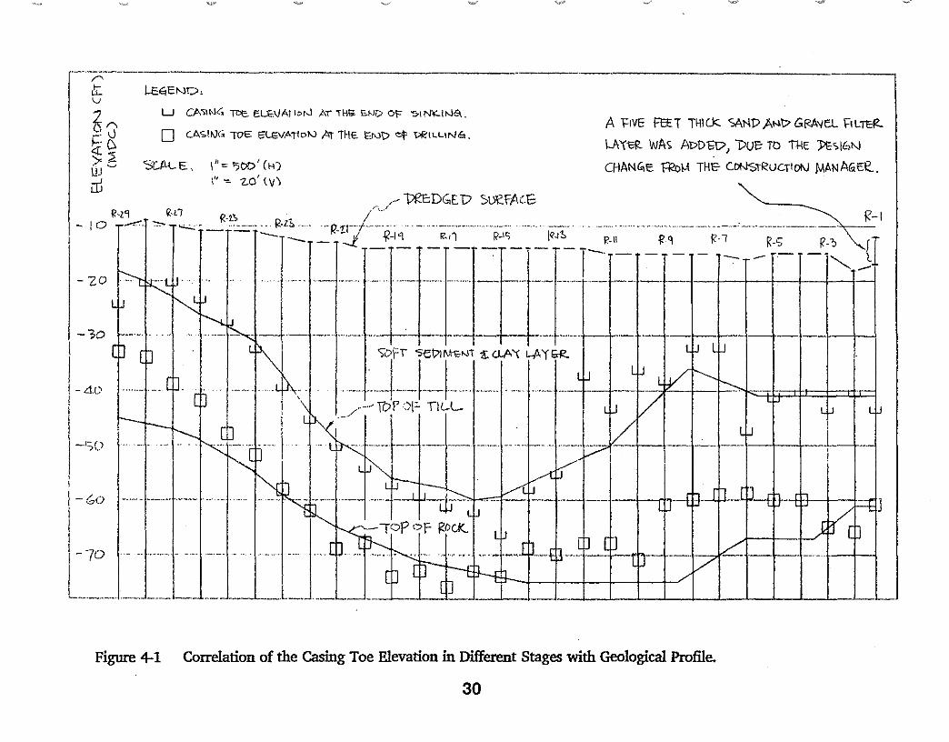
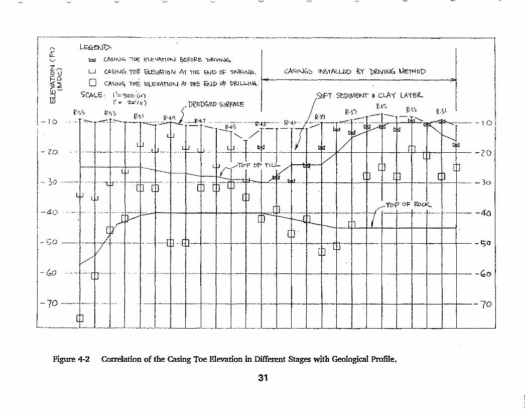
In order to identify the cause of the accident, all the settlement data relating to the casing A were tabulated in Tables 4-1 through 4-3. In addition, Figures 4-1 and 4-2 presented the correlation between the geological profile and the casing toe evaluation at different stages. Based on the review of the above infonnation, OSHA arrived at the following findings:
(1) The damage of the casing A from driving was due to the hard driving (5 blow/in) of this casing in the till layer.
(2) It appeared that no such damage would occur, if limited driving (1 blow/in) of this casing in the till layer would take place.
(3) There was no infonnation to demonstrate that the casing would be damaged from driving in the soft sediment and clay layer.
(4) Under the weight of the casing, the drill unit and the BHA, the sinking depth of the casing A was approximately equal to the entire thickness of the soft sediment and clay layer.
(5) The geotechnical infonnation contained in the contract documents closely reflected the existing site conditions and should have been sufficient to properly install casing A.
From Appendix A, the ultimate bearing capacity of the casing A on top of a 5 feet thick angular sand and gravel layer was estimated as 127 tons. Thus, the accident is interpreted as follows:
o When the 85 ton load of the casing A and the drill unit was imposed on the backfill layer, the system did not fail because the ultimate capacity of the soft sediment layer, computed to be 127 tons, was higher than the imposed load. (See Appendix A)
o Even with the tappings, the total weight might have increased to 120 tons, but still remained less than 127 tons.
o When the casing Awas cut-off 15 feet, the total weight was reduced to 81 tons with the drill unit.
o When the bottom hole assembly was added to the system, the total weight was increased to 161 tons, greater than the ultimate bearing capacity of the soft sediment layer. The soft sediment layer, therefore, failed first following which the
25
)
granular backfill lost all its confinement and its internal friction. Then, the casing A penetrated through the granular backfill losing most of its bearing area. The bearing capacity was reduced from 127 tons to 0.64 ton. (See Appendix A.) Even with the weight of the bottom hole assembly supported by the crane after the initiation of the sudden drop of the casings, the casing A had to penetrate a total of 30 feet to develop adequate skin friction from the clay to balance the 81 ton load.
4.2 Conclusion
Based on the results of the investigation, Occupational Safety and Health Administration concludes that:
)
1. The accident was caused by the drop of the steel pipe supporting casing into the soft ocean sediment layer when the casing, having penetrated through the five feet granular backfill, suddenly lost its bearing support. The sudden loss of the bearing support occurred when the dead load of the "bottom hole assembly" was imposed on the casing resulting in a total load in excess of the ultimate bearing capacity of the soft sediment. Subsequently, the platform doors of the drill unit were pushed upward by the wider flange of the bottom hole assembly. A worker was thrown up by the platform doors and fell half way into the top of the casing and later died. Two other workers standing on the fixed part of the platform, fell over each other, sustaining injuries.
2. This sudden and fast drop of the supporting casing with the drill unit could have been expected to occur, based on the geotechnical information available
) to the Contractor before the accident and the installation experience gained by him earlier in the project. In other words, the Contractor could have reasonably expected the supporting casing to penetrate through the entire thickness of the soft sediment under the weight of the casing, the drill unit and the bottom hole assembly. In addition, the Contractor could have fully evaluated the impacts of the granulate backfill, a known factor, on the installation procedure.
3. It was an unsafe practice on the part of the Contractor to allow the employees to work on the drill platform, while the supporting casing was not adequately founded on the firm soil strata and a significant weight was being added onto the system.
26
~ ~~ '"-"
TABLE 4-1 Estimated Depth of Settlements of Casing A (Installed by the Driving Method)
Riser Installation Elevation of Elevation of the Initial length Estimated Depth of Settlements Estimated Toe Elevation Number Date Dredged Seabed
(MOC) JOB (MOC)
of the Casing A (Ft) Casing A Alone Add the
Drive Unit After the Driving
After the Drilling
Before the Driving
After the Drilling
30 05/08/91 -11 +133 200 7 0 6 1 -18 -25
31 05/08/91 -09 +133 200 1 0 10 8 -10 -28
32 05/31/91 -10 +138 180 1 0 7 3 -11 -21
33 05/31/91 -08 +138 180 2 0 7 2 -10 -19
34 06/13/91 -08 +134 180 5 0 8 7 -13 -28
35 06/13/91 -07 +134 178 5 2 9 2 -14 -25
36 06/25/91 -08 +137 180 3 1 11 5 -12 -28
37 06/25/91 -09 +137 180 2 3 11 19 -14 -44
38 07/08/91 -10 +140 194 3 0 12 26 -13 -51
39 07/08/91 -10 +140 200 8 1 15 19 -19 -53
40 07/18/91 -12 +138 210 12 1 5 12 -25 -42
41 07/18/91 -12 +138 210 17 1 3 14 -30 -47
42 07/28/91 -12 +138 210 16 1 4 5 -29 -38
43 07/28/91 -12 +138 210 7 0 6 17 -19 -42
Notes: (1) The weight of the drive unit was assumed as 30 toIlS. (2) Riser No. 38 was the only hole driven by the VIbratory hammer. (3) There were only limited driving for Risers No. 40 through 43 in the ti1llayer. (4) The elevation of the top of the rock is varied from -45 to -40.
27
,,,"y'.,/
TABLE 4-2 Estimated Depth of Settlements of Casing A (Installed by the Sinking Method)
Riser Installation Elevation of Dredged Elevation of the JOB Initial length of Estimated Depth of Settlements Estimated Toe Elevation Number Date Seabed (MOC) (MOC) the Casing A (Pt)
Casing A Add the Add the After the Before the After the Alone Drill Unit BHA Drilling Drilling Drilling
44 08/08/91 -16 138 200 14 5 -30 -35
45 08/08/91 -13 138 200 5 13 -19 -31
46 08/25/91 -12 138 200 13 7 -25 -32
47 08/25/91 -11 138 200 9 12 -20 -32
48 09/03/91 -11 141 200 7 32 -18 -50
49 09/03/91 -10 141 200 5 35 -15 -50
50 09/11/91 -11 137 190 9 12 -20 -32
51 09/11/91 -10 137 188 8 14 -18 -32
52 09/19/91 -10 137 201 17 15 -27 -42
53 09/19/91 -9 137 202 22 15 -31 -46
29 09/26/91 -10 139 182 15 8 -25 -33
28 09/26/91 -9 139 181 12 13 -21 -34
27 10/03/91 -10 136 198 11 18 -21 -39
26 10/03/91 -11 136 200 13 18 -24 -42
25 10/14/91 -11 138 191 17 20 -28 -48
24 10/14/91 -11 138 193 22 19 -33 -52
23 10/25/91 -12 137 201 28 18 -40 -58
22 10/25/91 -13 137 206 33 16 -46 -62
21 11/12191 -13 140 210 38 18 -51 -69
20 11/12191 -14 140 211 41 13 -55 -68
54 11/22191 -10 140 211 26 25 -36 -61
55 11/22191 -9 140 210 26 40 -35 -75
28
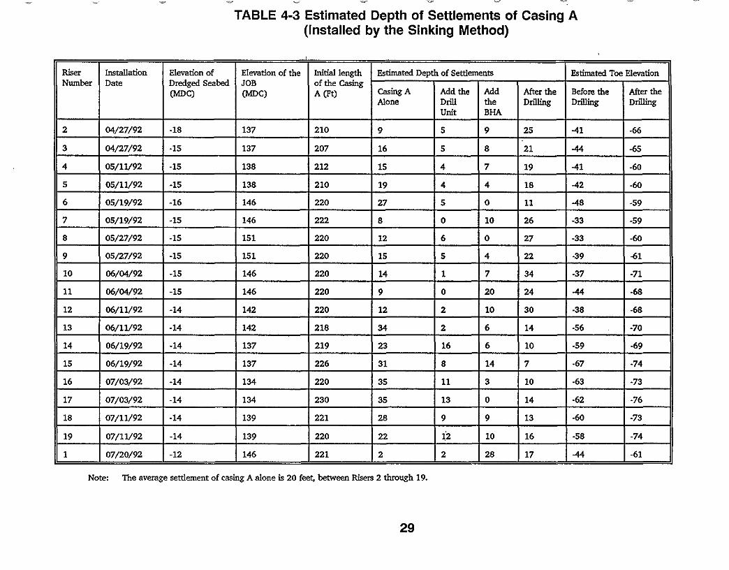
TABLE 4-3 Estimated Depth of Settlements of Casing A (Installed by the Sinking Method)
,
Riser Installation Elevation of Elevation of the Initial length Estimated Depth of Settlements Estimated Toe Elevation Number Date Dredged Seabed JOB of the Casing
Casing A Add the Add Before the After theAfter the(MOC) (MOC) A (Ft) Alone Drill the Drilling Drilling Drilling
Unit BHA
2 04/27/92 -18 137 210 5 25 -419 9 -66
3 13704/27/92 -15 207 5 816 21 -44 -65
4 05/11/92 -15 138 212 15 4 7 -4119 -60
5 05/11/92 -15 138 210 4 18 -42 -6019 4
6 05/19/92 -16 146 220 027 5 11 -48 -59
05/19/92 ·15 146 2227 8 0 10 26 -33 -59
8 OS/27/92 -15 151 220 12 6 0 27 -33 -60
OS/27/92 -15 151 220 59 15 4 22 -39 -61
10 06/04/92 -15 146 220 14 1 7 34 -37 -71
11 06/04/92 -15 146 220 0 20 -6824 -449
12 06/11/92 142 220 12 2 10 30 -38 -68-14
13 06/11/92 -14 142 218 2 6 14 -5634 -70
14 06/19/92 137 219 16 6-14 23 10 -59 -69
15 06/19/92 137 226 31 8 14-14 7 -67 -74
16 07/03/92 134 220 3 10 -63-14 35 11 -73
17 07/03/92 134 230 13 0 -62·14 35 14 -76
18 07/11/92 139 221 28 13 -60-14 9 9 -73
220 10 -5819 07/11/92 -14 139 22 16 -741:2
146 221 281 07/20/92 -12 2 2 17 -44 -61
Note: The average settlement of casing A alone is 20 feet, between Risers 2 through 19.
29
--
...,/
" Ii::. U=G,Ei'l!::>, v
U CASII'U; Toe EL.HIA) IoN AT';~ H.lD of 'Sl N;:.1i'J!E<. A l=1VE FaT THiCk SIINP )\1'1t> Gf<A'IEL. j:IL~~'0 o C.A<;I!IJ(; TOE "'LEVAr1D'" Ar lHIO nut> ':f Pf<ILLlN6.
~.C> !-A'f-eF- WAs ADDB17, l/ue TO tHE Jl\;;'>IC~W ~;a UJ '-' 'SC.tlt.. IS .. \"= ')00' (>4) CHANG,E fl2c}.,\ THE- CoNsTRUCTlDI\l M"NA(,lt~.
\'i -::. 1.0' (v)ill ,.- VRE:DGEP SUi?fA(·S
i-I 0 'F-"j ~'i~j-'i'T-"::': ~'d'-:,,-.~;-~,- ..i"'. ·;,,·,;--,;----;:;-~:I -<0 -- . .. .. - -- ··l-JJr[J]] I[[r:CrIJ~ """ j
I - ~o .-.. . ... ...... --. -. -I
'--~1;~t:t~~1~--' -- ..- -- '- Lt;"+-+-l I I 1-+ ._....-1- M--.----;-- ~----l·-··-J--l-·--·.._- --- ..----. - .. t-:=tt---t=J:t=F=::tf=ji ! I /_.., 17)r~)I- TIL-L. I I-so ..rb~. - i I H---.-.. -.- 0_._- -- "- -..~-. -----1·- .• .. -- .
j~n::-- -ttl - . .,.__~ ._.__••__.J_L .L_•.J. __L __.L_tf .. _ / L_
Figure 4-1 Correlation of the Casing Toe Elevation in Different Stages with Geological Profile.
30
---.. --..·-----·.... '- ,.... ,........ ----..... --.........- ...----..---,----,..... " LI;,Q-etS\),r. ll: v l»;I CASING, "lot IOLtVAr\oW &;FoR-E- 1>!'Jv,Nf" \ Zr- LAS,"-J(;~ INS1ALu;{) 1S'( DRJVI~ 1..1ejHOJ)0<J U CASING, TD" B.:EvATlbN AT 'I-\E. "Nt> 01= SINf:>l'J"". i=CI o CA~IN~ 1t>-E, Et..EVAnON Al mE- !:tOP D1' DR-ILLIlJ6" I... »I~::2
"'tALE:: I"= SOD '(H) SofT set>tr,-\tNT ~ CLA'{ LA'{SI1..I ~-!" - 7.0' IV) r DCE01)(,tD S\lI<FAcE I t.;; •
! r-·,"" l?"" \<.\") JU, R·~I1- 10, - 10 i
I -Zi)
1--+--+--+--+,,__ ToP bP ilL\..
:So --'--ll''''-''''---''-'' , . ---- ->0 ToP of Roc.K.
i dO-- --- ...... -' I I _.-. -·r·--f-- -40
i- ';0 ---' ------1--·-·1..-1--1-·..+--+-l----!---·-+----m---f---I-·+--l- I I I I - .. So
II '
1- (,,0 ,-,' "-W--+ - 1'" 1- .+ ...+....! ..··+---f----I-·--!----+--+-I----l---·---+-+-+--+·..I----l__+__!_+_+_ .. "0
70 ---~.:~.:_~:~~_ ...~~~~~.~~:.~._:!~.~:~~.~:-:~~~.~---~~:::: I I I I I I ! ! I -70 !
Figure 4-2 Correlation of the Casing Toe Elevation in Different Stages with Geological Profile.
31
5.0 REFERENCES
(1) Boston Harbor Project Shafts and Tunnels (1990), by L.A. Williamson, H.P. Caspe, and B.J. Van Weele, Tunneling Technology Newsletter.
(2) Effluent Outfall Tunnel and Diffusers, Contract Plan (1990), by Parsons Brinckerhoff, for Massachusetts Water Resources Authority.
(3) 1989 Marine Boring Program, Geotechnical Interpretive Report (1990), by Parsons Brinckerhoff Quade & Douglas, Inc.
(4) Design Manual 7.02, Foundations & Earth Structures (1986), by Naval Facilities Engineering Corrunand.
32
)
APPENDIXA GEOTECHNICAL EVALUATION AND CALCULATIONS
)
33
)
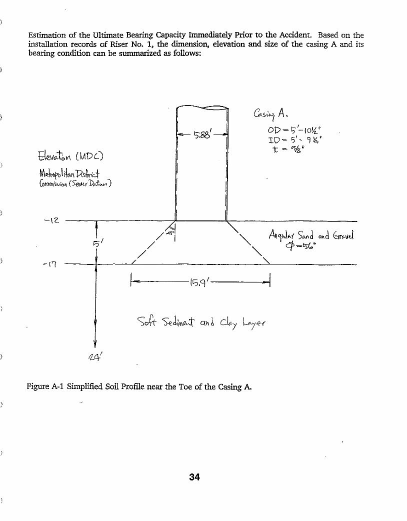
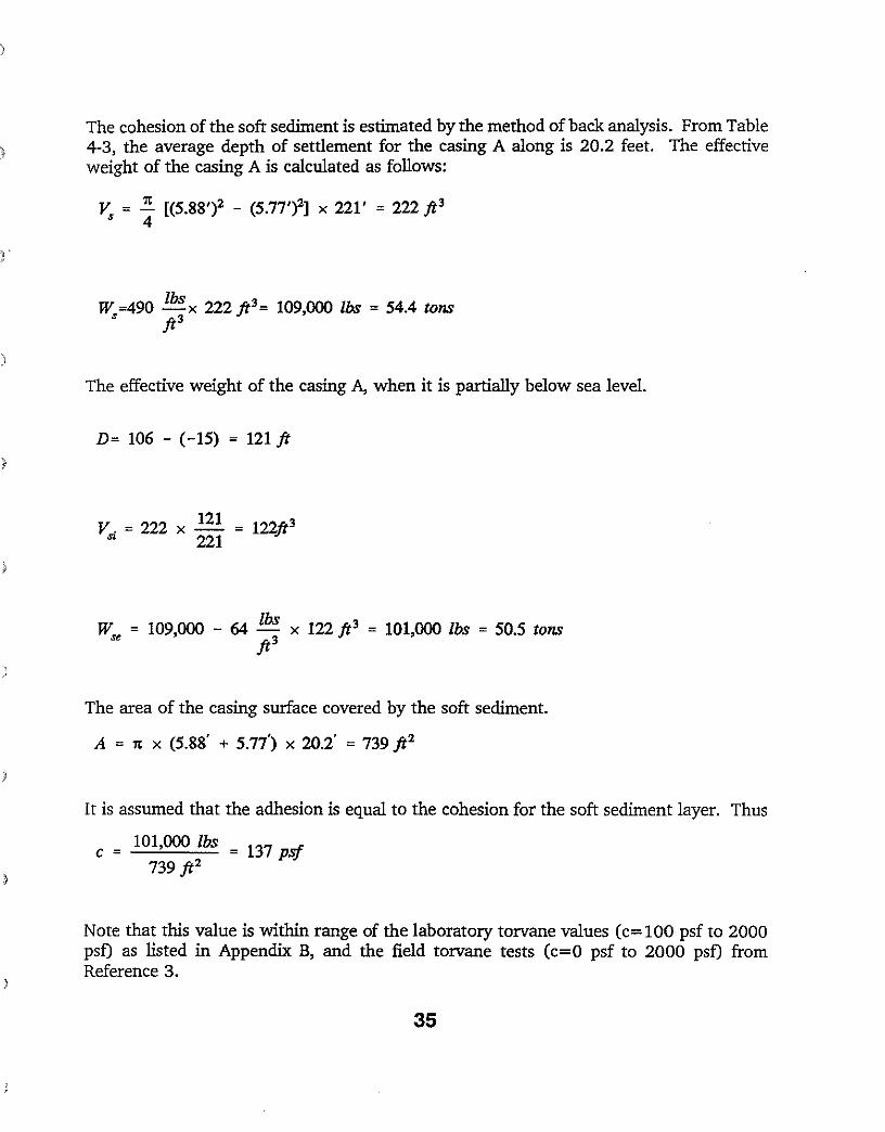
Estimation of the Ultimate Bearing Capacity Immediately Prior to the Accident. Based on the installation records of Riser No.1, the dimension, elevation and size of the casing A and its bearing condition can be summarized as follows:
tkW.ti:>VI (l.ADCj )
~\ikn l).$-\r,4 ~rni"\O>, (S'€Oltf1)"t",,,,,")
/~ / I
/ -1'1
c..Si"'f A, 01)= ;'-1O~('~~.MI-l ID= '5'- 'J!4' t = "'.i'
I I I I I
I_E~~~(C::;.CJ/-----1-1
)
Figure A-I Simplified Soil Profile near the Toe of the Casing A.
34
)
The cohesion of the soft sediment is estimated by the method of back analysis. From Table 4-3, the average depth of settlement for the casing A along is 20.2 feet. The effective weight of the casing A is calculated as follows:
v = ..::. [(5.88')2 - (5.77')2] x 221' = 222 ft3 s 4
W =490 lbs x 222 ft3 = 109,000 lbs = 54.4 tons S ft3
The effective weight of the casing A, when it is partially below sea level.
D= 106 - (-15) = 121ft
v = 222 x 121 = 122ft3 ~ 221
lbsW = 109,000 - 64 - x 122 ft3 = 101,000 lbs = 50.5 tons ~ ft3
)
The area of the casing surface covered by the soft sediment.
A = Tt x (5.88' + 5.77) x 20.2' = 739 ft2
It is assumed that the adhesion is equal to the cohesion for the soft sediment layer. Thus
c = 101,000 lbs = 137 psf 739 ft2
Note that this value is within range of the laboratory torvane values (c=100 psf to 2000 psf) as listed in Appendix B, and the field torvane tests (c=O psf to 2000 psf) from Reference 3.
J
35
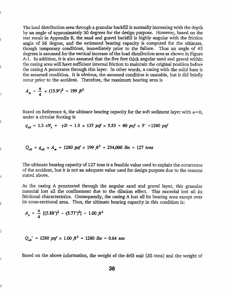
The load distribution area through a granular backfill is normally increasing with the depth by an angle of approximately 30 degrees for the design purpose. However, based on the test result in Appendix B, the sand and gravel backfill is highly angular with the friction angle of 56 degree, and the estimated bearing capacity is computed for the ultimate, though temporary conditions, immediately prior to the failure. Thus an angle of 45 degrees is assumed for the vertical increase of the load distribution area as shown in Figure A-I. In addition, it is also assumed that the five feet thick angular sand and gravel within the casing area will have sufficient internal friction to maintain the original position before the casing A penetrates through this layer. In other words, a casing with the solid base is the assumed condition. It is obvious, the assumed condition is unstable, but it did briefly occur prior to the accident. Therefore, the maximum bearing area is
Based on Reference 4, the ultimate bearing capacity for the soft sediment layer with 0=0, under a circular footing is
quit = 1.3 eN, + yD = 1.3 x 137 psf x 5.53 + 60 pel x 5' =1280 psf
Quit = quit x Am = 1280 psf x 199 ft2 = 254,000 Ibs = 127 tons
The ultimate bearing capacity of 127 tons is a feasible value used to explain the occurrence of the accident, but it is not an adequate value used for design purpose due to the reasons stated above.
As the casing A penetrated through the angular sand and gravel layer, this granular material lost all the confinement due to the dilation effect. This material lost all its frictional characteristics. Consequently, the casing A lost all its bearing area except over its cross-sectional area. Thus, the ultimate bearing capacity in this condition is:
Quit' = 1280 psf x 1.00 ft2 = 1280 Ibs = 0.64 ton
Based on the above information, the weight of the drill unit (35 tons) and the weight of
36
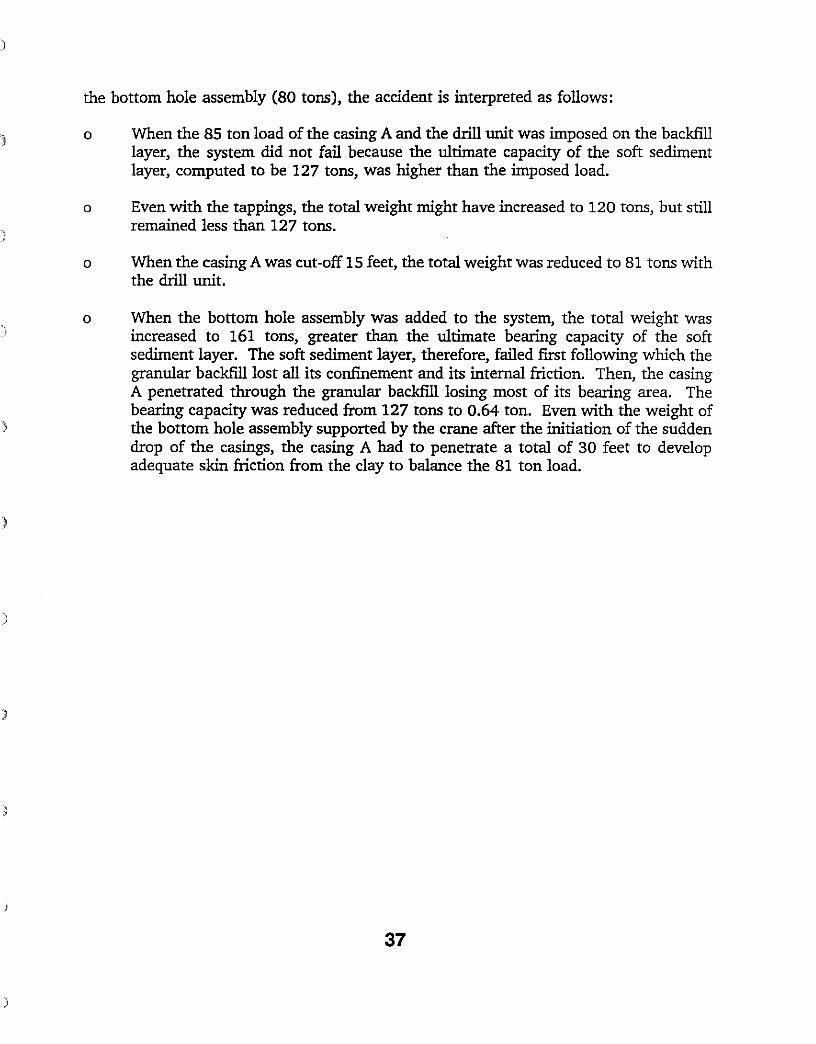
the bottom hole assembly (80 tons), the accident is interpreted as follows:
o When the 85 ton load of the casing A and the drill unit was imposed on the backfill layer, the system did not fail because the ultimate capacity of the soft sediment layer, computed to be 127 tons, was higher than the imposed load.
o Even with the tappings, the total weight might have increased to 120 tons, but still remained less than 127 tons.
o When the casing A was cut-off 15 feet, the total weight was reduced to 81 tons with the drill unit.
o When the bottom hole assembly was added to the system, the total weight was increased to 161 tons, greater than the ultimate bearing capacity of the soft sediment layer. The soft sediment layer, therefore, failed first following which the granular backfill lost all its confinement and its internal friction. Then, the casing A penetrated through the granular backfill losing most of its bearing area. The bearing capacity was reduced from 127 tons to 0.64 ton. Even with the weight of the bottom hole assembly supported by the crane after the initiation of the sudden drop of the casings, the casing A had to penetrate a total of 30 feet to develop adequate skin friction from the clay to balance the 81 ton load.
)
}
37

APPENDIX B SUMMARY OF LABORATORY TEST RESULTS
38
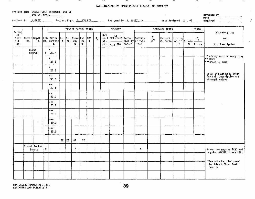
LABORATORY TESTING DATA SUMMARY
Project Name OCEAN FLOOR SEDIMENT TESTING BOSTON. MASS.
Revfewed by ======= Date Pro j ec t No. -b.L1c;3~OCL7L7 _ project Engr. D. SCHULZE Assigned By J. SCOTT JIN Date Assigned OCT. 92 Required
Boring or
Test Pit
No.
Sample No.
Depth ft.
Lab No.
IDENTIFICATION TESTS DENSITY
Permeabll lty em/sec
STRENGTH TESTS CONSOL. Laboratory Log
and
Soil Description
Water Content
%
* 24.7
* 21.2
*
LL %
PL %
Sieve -200
%
Hyd -2~ %
ORG %
Gs Dry unit wt. pef
MAXY?pcf) Torvane or Type Test
-a psI'
Failure Criteria
a1 • a3 or T psf
Strail') %
Cc
1 + eOWoPt (%)
BLOCK SAMPLE ,
* clayey sand or sandy cLay** CLay ***gravelly sand
24.8
** 30.0
**
Note: See Attached sheet for Soil Description and strength values
29.1
** 32.0
*** 25.2
*** 25.0
*** 19.9
*** 23.9
32 23 41 12
Gravel Bucket Sample 2 5 * Brown m~c angular SAND and
angular GRAVEL, trace Silt
*See attached plot sheet for Direct Sheer Test results
GZA GEOENVIRONMENTAL. INC. ENGINEERS AND SCIENTISTS 39
-- - -
- - - -
••
--
100 90
'0 00z",
wN '0
00 HZ
(f)
0 0 zW '"
> ~g~ (f)
°00a: z'" <l: 0 Z <l: '0 I- ~ .. (f)
(f) . .0..,
Z ::J
'" ...... % _H
..,. ..... z <'>H
-is
'''is
PERCENT FINER BY WEIGHT 80 70 60 50 40 30 20 10 cr.'
a -y:J
1/
I1l
l)
a
H
C\l
/
II - -
I If' I1J
-f- - f- I- - - - - j - - - - - -
f- - 1- - - - -
7'
-I
V
1/ - - - - - - - - -
../ /
",
/
/
f- - - - - - - - - - - - - - - - - - -
f- f- f- - - - - - - - - - - - - - - - -
..... ~... -' u
-
C\l, a ...
-'"'"' H
'"
en 0: w I W-, :L
at-! "'"'-l
-l w Zt-! :;:::L
Z t-!
0 Z
W ... N "'" ::;at-! "
w :E..... en
Z t-! w <:( '" "... 00:
'-' (!)
W Za H ..... ....
~ w >... " '"
w
'" ... " a '-'
a .....
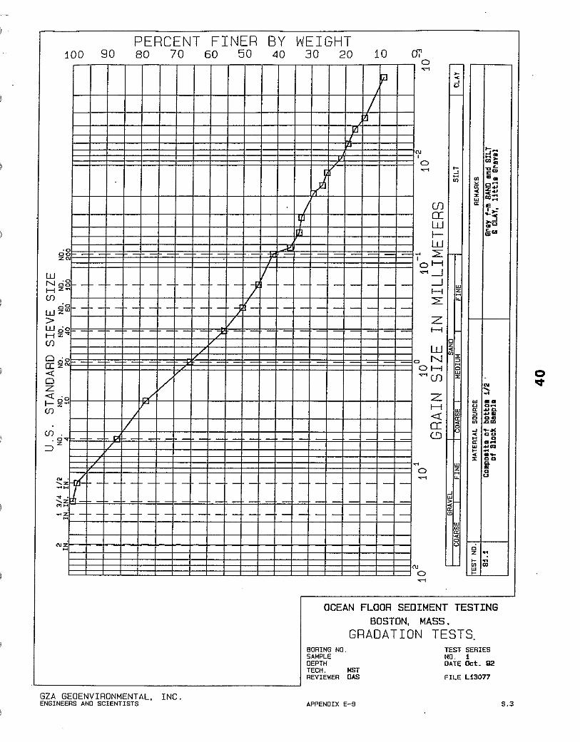
OCEAN FLOOR SEDIMENT TESTING
~-H·CoOt ~L c'"a.
" ~ OH '" z'"... % ..'"00;::w
I • " "->~::l .u /j;"
N .....-w 0_
::Hr" ae0
'" ..,00 "u
_... ~ ... au H .... w
H "'''.-00" i
.."... 0
a U
..ci -:Z
00 w..'" H
BORING NO, SAMPLE DEPTH TECH. REVIEWER
BOSTON, MASS. GRADATION TESTS
TEST SEAlES NO. 1 DATE Oct. Q2
MST OAS FILE L130n
GZA GEOENVIRONMENTAL. INC. ENGINEERS AND SCIENTISTS APPENDIX E-9 S.3
- - --
--
---- - - - -
100 90
WN
00 HZ ...
(fl
0 0
>w z '"
W '0 H~""l (fl
°00a: z'" <l: 0 Z <l: '0
I--- ~-(fl
(fl. .0..,
Z :::::J
'" . ~"l .., . '-.z <'>H
... z H
",z H
PERCENT FINER BY WEIGHT 80 70 60 50 40 30 20 10 (),'
0
'0 00 Z'"
'01- I- 1- - - - - - - - - - - - - - t -- - - - - - - - - - - - - - - - -
/
/
V /'
,/
,/
- 1- I- - - - - - - - - - - - - - - - -
1- 1- 1- - - - - - - - - - - - - - -
r ..,.; >< -' u
e-
N, 0 ..,.; ~
~
'"
(fJ
0:: W ~ W ... 2:
I oH ..,.;...-J
...-J w zH " "2:
z H
" ..W z
"'z 0 N
c:" OH w"";(fJ z
Z H <t co..'"w
0:: u " c..':J
~ w 0 ;;'; ..,.; "
..-'W > co
'" '" ..W
co
u " N
0 ..,.;
0 Z
<lid ..c.> ~ ...
"co",,"' ...'" Qc."co.. ~
~C1C1Z "u co w u" ..I Qc.
e~+,
11"0 OC ..c."
w u .. " co
.,.. Co " .. .. '" 0
-'
..
... " u
H
..cow
.. .><
~
z
a ...z .,OJ
w '" ~
~
OCEAN FLOOR SEDIMENT TESTING BOSTON, MASS.
GRADATION TESTS BOAING NO. SAMPLE DEPTH TECH. NST REVIEWER CAS
GZA GEOENVIRONMENTAL, INC. ENGINEERS AND SCIENTISTS APPENDIX E-9
TEST· SERIES NO. 2 DATE Oct. Q2
FILE U,30n
S.3
Membrane Type:
N/A
Samp Ie Deser I pt Ion:
B~own m-c angular SAND and (9 angu I ar GRAVEL, traee S lit(9 (9 '<l (9 (9 <0 I')
(9 (9 (\J I')
(9 (9 (jJ (\I
LL (9 (Ij (9
'<l (\I0: (9 (9vi (9
(f) (\Iw
(9a (9J
(f) <0 ... cr (9-0: (9W (\JI ... (f)
& & OJ
& & '<l
P. s. F.
......, "",y
/1/
/
1//X
1/ /
II /
II /
.I~.,· 400 800 1200 161210 2000 2400 2800 3200 3600 40012
NORMAL STRESS,
42 GZA GeoEnv 1r-onmeryto l , Inc.
END POINT PEAK STRESS: PSF RESIDUAL STRESS: PSF
NUMBER SHEAR
TEST
NORMAL SHEAR NORMAL
OS2. 1 + 1175 500 714 500 OS2. 2 X 2076 1000 1471 1000
RESIDUAL STRESS: PSF RESIDUAL STRESS: PSF NUMBER
SHEAR
TEST
NORMAL SHEAR NORMAL
OS2.1 + OS2.2 X
OCEAN FLOOR SEDIMENT TESTING BOSTON, MASS.
DIRECT SHEAR TEST MOHR ENVELOPE
Tech: MST Date: 10-28-92
Rev I ewer: DAS F I I e No: L13077
3. 5
3. 0
~
Z "U I ~
2. 5 W W m l
.jJ (/)
-o 2.0 E l 0 Z
"W ~ 1. 5 m L I~ .jJ (f)
L 0 (j)o 1. 0
111 I I I I I I I I I I I I I I I I I I I I L L 0 0
0. 5
(. 2. 0
Shea~ Displacement (Inches) 43GZA GeoEnv i ronmenta l. Inc.
0. 0 0. 4 0. 8 1.2 1.6
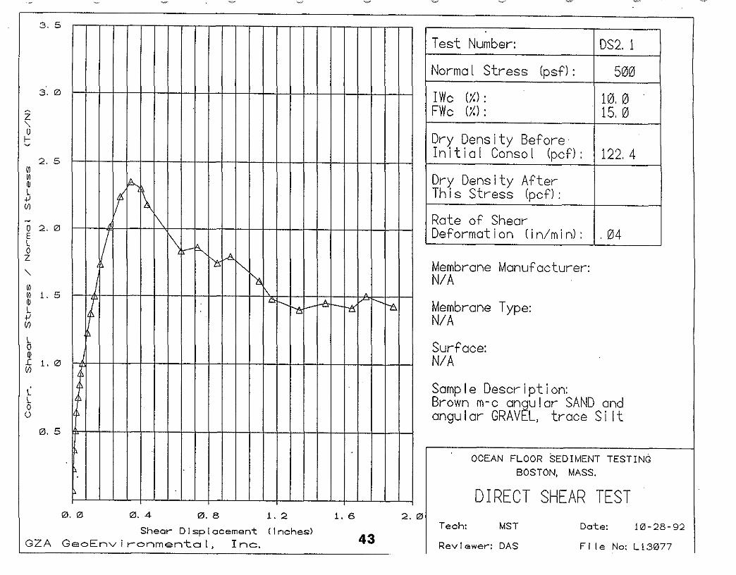
Test Number: DS2. 1
Norma I Stress (psf): 500
Membrane Manufacturer: N/A
Membrane Type:N/A
Surface: N/A
Rate of Shear Deformation (in/min): 1.04
10.0 15.0
122.4
Dry Density After This stress (pcf):
IWc (1.): FWc (1.):
Dry Density Before In i t ia I Canso I (pcf):
Sample Description:Brown m-c angular SAND and angular GRAVEL, trace Si It
OCEAN FLOOR SEDIMENT TESTING BOSTON, MASS.
DIRECT SHEAR TEST Tech: MST
Rev I ewe~: DAS
Date: j 0 - 28 - 92
File No: Ll3077
\_J~ -3. 5
3. 0
z ~
"U f
2. 5 ~ ~ m L +' II)
-o 2.0 E L o Z
"~ ~ 1. 5 (j) L +' I/)
L o (j)
~ 1. 0
L L o o
0. 5
!I',
~ ~1'~ 1b
! zI~
t '1j
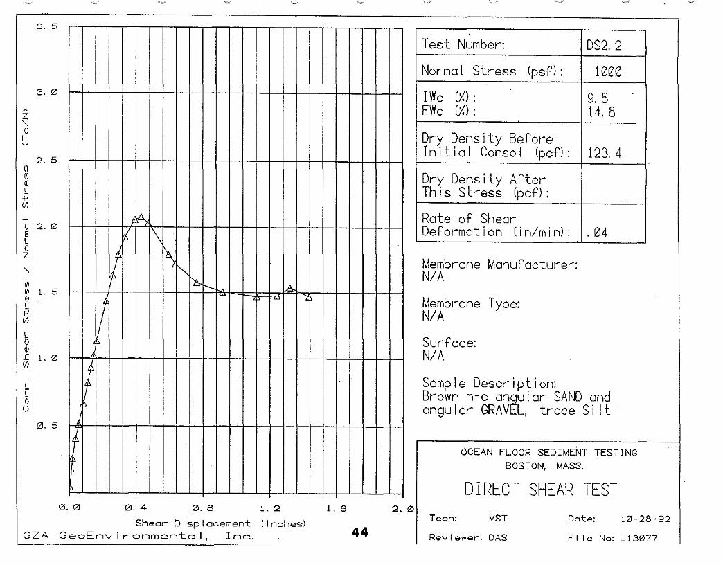
Test Number: DS2. 2
Norma I Stress (pst): 1000
IWc FWc
(.1.): (.1.):
9. 5 14, 8
Dry Density Before' In it ia I Canso I (pefl: 123.4
Dry Density After This stress (pef):
Rate of Shear Deformation (in/min): 1,04
Membrane Manufacturer: N/A
Membrane Type:N/A
Surface: N/A
Sample Description:Brown m-c angular SAND and angular GRAVEL, trace Si It·
OCEAN FLOOR SEDIMENT
BOSTON, MASS.
TESTING
DIRECT SHEAR TEST
GZA Shea.. D I sp I acement
GeoEnv i ,.-onmenta I, Inc.
0. 0 0. 4 0. 8
(I nches)
1.2 1.6
44
2. 0 Tech:
Rev 1ewer:
MST
DAS
Date:
F I I e No:
10-28-92
Ll3077
)
LAaORATORY TEST PROCEDURES
OCEAN FLOOR SEDIMENT TESTING BOSTON, MASS.
L13077
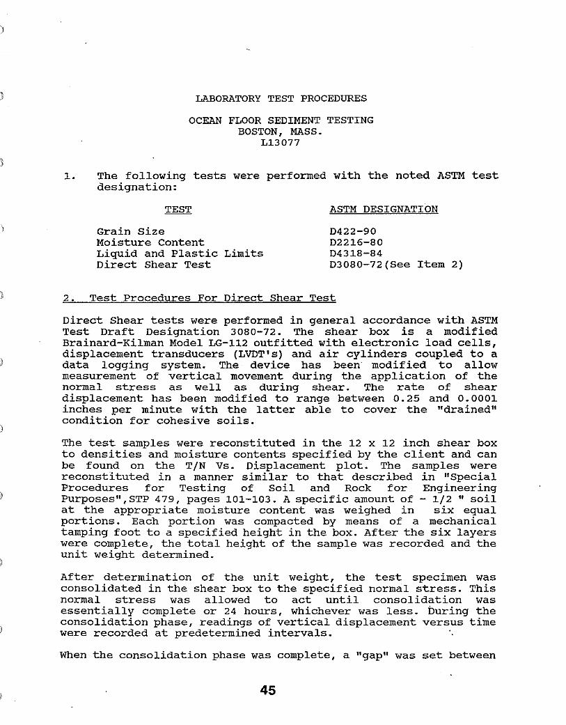
1. The following tests were performed with the noted ASTM test designation:
ASTM DESIGNATION
Grain size D422-90 Moisture Content D2216-80 Liquid and Plastic Limits D4318-84 Direct Shear Test D3080-72(See Item 2)
2. Test Procedures For Direct Shear Test
Direct Shear tests were performed in general accordance with ASTM Test Draft Designation 3080-72. The shear box is a modified Brainard-Kilman Model LG-112 outfitted with electronic load cells, displacement transducers (LVDT's) and air cylinders coupled to a data logging system. The device has been modified to allow measurement of vertical movement during the application of the normal stress as well as during shear. The rate of shear displacement has been modified to range between 0.25 and 0.0001 inches per minute with the latter able to cover the "drained" condition for cohesive soils.
)
The test samples were reconstituted in the 12 x 12 inch shear box to densities and moisture contents specified by the client and can be found on the TIN Vs. Displacement plot. The samples were reconstituted in a manner similar to that described in "Special Procedures for Testing of Soil and Rock for Engineering Purposes",STP 479, pages 101-103. A specific amount of - 1/2 " soil at the appropriate moisture content was weighed in six equal portions. Each portion was compacted by means of a mechanical tamping foot to a specified height in the box. After the six layers were complete, the total height of the sample was recorded and the unit weight determined.
After determination of the unit weight, the test specimen was consolidated in the shear box to the specified normal stress. This normal stress was allowed to act until consolidation was essentially complete or 24 hours, whichever was less. buring the consolidation phase, readings of vertical displacement versus time were recorded at predetermined intervals.
When the consolidation phase was complete, a "gap" was set between
45
the upper and lower shear boxes which would force the failure to occur in this zone. Shearing then took place at a rate of shear displacement of 0.04 in/min. During application of the shearing phase, readings of shear load, shear displacement, and vertical displacement were recorded at regular intervals. After the "peak" and "residual" shear strengths were defined or when the end point of shear travel was reached the sample was removed from the test apparatus and its moisture content dete~ined.
For determination of the Mohr Envelope plot, subsequent samples were set up and run as outlined above at different normal stresses.
)
)
46
i
OCEAN FWOR SEDIMENT TESTING BWCKSAMPLE DESCRIPTION
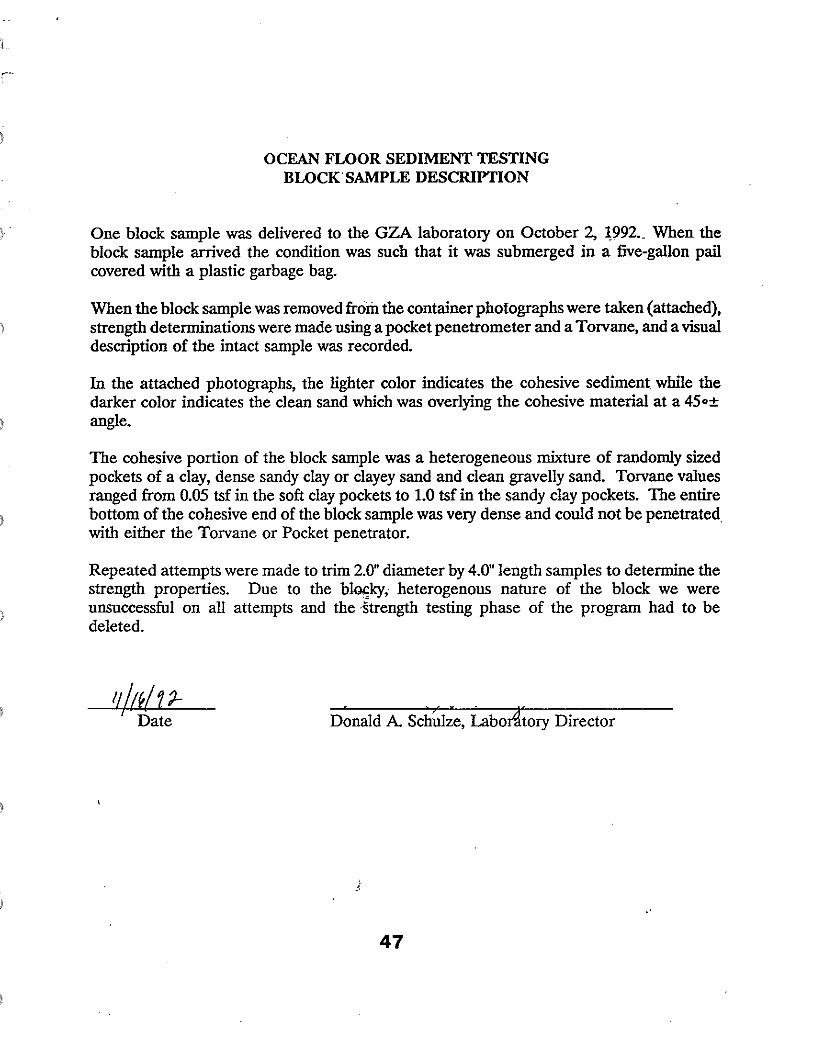
One block sample was delivered to the GZA laboratory on October 2, ~992._ When the block sample arrived the condition was such that it was submerged in a five-gallon pail covered with a plastic garbage bag.
When the block sample was removed from the container photographs were taken (attached), a Torvane, and a visual strength determinations were made using a pocket penetrometer and
description of the intact sample was recorded.
In the attached photographs, the lighter color indicates the cohesive sediment while the darker color indicates the clean sand which was overlying the cohesive material at a 45o± angle.
The cohesive portion of the block sample was a heterogeneous mixture of randomly sized pockets of a clay, dense sandy clay or clayey sand and clean gravelly sand. Torvane values ranged from 0.05 tsf in the soft clay pockets to 1.0 tsf in the sandy clay pockets. The entire bottom of the cohesive end of the block sample was very dense and could not be penetrated with either the Torvane or Pocket penetrator.
Repeated attempts were made to trim 2.0" diameter by 4.0" length samples to determine the strength properties. Due to the b~kyi heterogenous nature of the block we were unsuccessful on all attempts and the -strength testing phase of the program had to be deleted.
Date
47