Embed Size (px)
DESCRIPTION
investigation of Fine Structure of textile Fibre
Citation preview
FINE STRUCTURE OF FIBRE A fiber is defined as a unit matter characterized by flexiblity, fineness, and a high
ratio of length sufficient high temperature stability and a certain minimum
strength and extension are also required.
Fine structure relates to the physical arrangements of molecules
constituting the fiber from general consideration and also chemical analysis it is
known that the molecules constituting the fiber are considerably long as
compared to their width. Further these molecules are made a large number of
smaller units called monomers repeating them several times. For this reason
these fiber forming molecule are called as polymers (derived from Latin word
poly-many and mer-unit).the unit of the polymer is the monomer, it is also
derived from the Latin word mono-one. At the molecular level the polymer is
extremely long and linear, whereas the monomer is very small. Monomers are
usually chemically reactive where as the polymers are unreactive. “The chemical
reaction which causes the monomers to join end to end to form a polymer is
called polymerization.”
Polymer are chemically unreactive this does not prevent its being subsequently
attacked by chemicals and other degrading agents. The length of the polymer is
important .all fibbers both of man-made or natural have to extremely long
polymers. For measuring the length of the polymer is a complicated task and can
be determined by its DEGREE OF POLYMERISATION.
Degree of polymerization = average molecular weight of the polymer
Molecular weight in repeating unit in the polymer

METHODS OF INVESTIGATION OF FINE STRUCTURE The optical methods are not suitable for this purpose, since the smallest object
which cannot be seen with the help of visible light is equal to its wavelength
which is in the range of 0.5µ where as the molecules have dimensions of the
order of few Ao . So we have to use the waves or rays which have a very fine wave
length ( prefferably high frequency). Infrared rays,X-rays,and electron beam are
used for investigation of fine structure of fiber.
Infrared red rays The infrared radiation gives the idea about the atoms constituting the moleculrs
and the type of bonds between them. Where as the X-ray gives the idea about the
physical arrangement of the molecules,and the electron beam gives the idea very
much enlarged images of fine stucture as agains the indiret information given by
X-rays and infrared rays.
The infrared radiation are composed of electromagnetic waves whose
wave length varies between 1 µ -15 µ. When these rays are passed through the
material , it is mostly absorbed at certain characterstic frequency. With the help
of the sprectometer the variation in the absorption can found and plotted against
wave length of more commonly called wave number.
The wave number on which the absorption takes place depend upon the
nature of two atoms and the bond between them. The absorption frequency of
such group are as ≥C-H,>C=O, C-O-,-O-H-,>N-H, ,>C=C and so on. To a
smaller extent it also depends upon the group of its neighborhoods. For example
the absorption frequency for a carbon hydrogen bond in a terminant group is
different from that for the same bond in(-CH2 -) therefore infrared spectroscopy
can help in deducting the chemical structure of fiber. This method can also be
used for estimating quantity of substance like water and other chemical present
in the fiber.
Further if infrared rays are polarized than they give maximum absorption for
orientation and minimum absorption at an orientation at right angles. This is also
known as infrared diachroism. This can be used in investigate the degree of
orientation of molecule in the fiber.
An advantage of the infrared absorption meted is that it is influenced by all the
molecule in the fiber in both the crystalline and non-crystalline regions. Whereas
X-ray diffraction method gives detailed information only about crystalline region.
One of the major techniques involves exposure of a material to the vapour of the
heavy water (D2O) there by replacement of hydrogen atoms by deuterium atoms.
In case of the fibers only non crystalline region are assessable to heavy water.
Hydrogen atom of this entire region will be replaced by deuterium. Whereas as
those in crystalline region will remain unaffected. From this difference in infrared
absorption the percentage of two regions can be estimated.
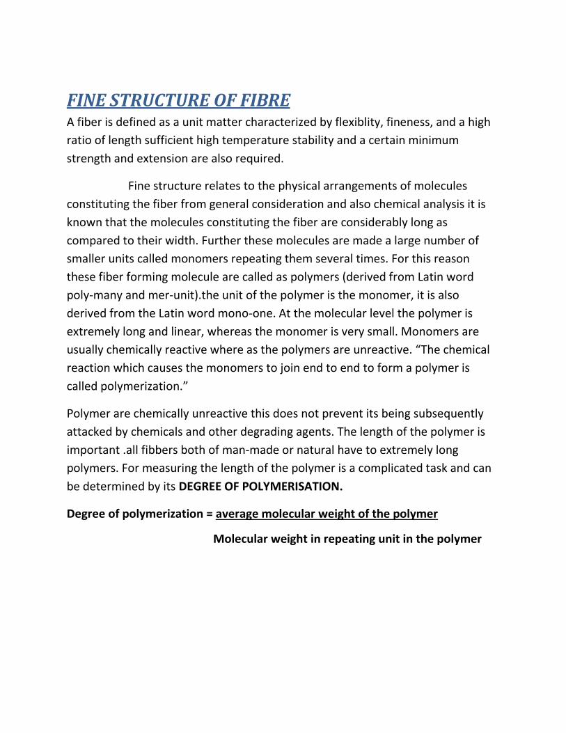
X-RAY DIFFRACTION METHOD If a beam of X-ray is directed at a crystalline region it is strongly reflected
whenever it strikes the layer of atoms at an angle θ such that
nλ=2dsinθ
Where, n=integer, λ=wavelength of X-ray, d= distance between atomic layer.
Under this condition the reflection from individual layer rain force each other
since they are in phase with each other whereas at other angle they interface
with one another.
There may be many layers of atoms of varying density in different direction. There
will be a series of characteristics angle for each case. From these angles and from
the variation in the intensity of reflection, the general crystal structure can be
work out.
In fibers we are not dealing with single crystal there will be a lot of small crystal
and they are oriented parallel to the fiber axis. But it is simpler to consider first
the diffraction pattern which is found where there is no preferred orientation.
This is what we get, the process of passing an X-ray beam through powdered
crystals is called powder photograph.
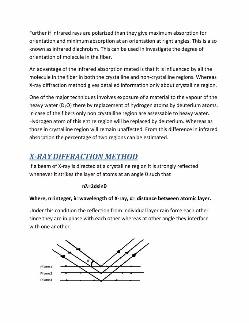
For a strong reflection to occur the layer of atoms should make the required angle
with X-ray beam. This will happen for a series of orientation of crystals distributed
around a cone. The X-rays will be reflected around a cone of twice this angle. Due
to this all the orientation present and all the other reflection will occur with the
appropriate layers of the atoms distributed around the cones given in a
characteristic angle of incidence.
Thus, the powdered photograph, therefore series of circles subtending angle can
be determined by the distance between the layers of the atoms.
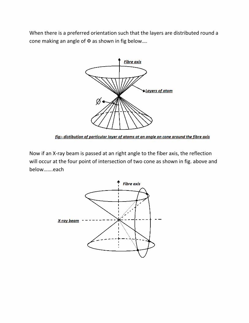
When there is a preferred orientation such that the layers are distributed round a
cone making an angle of Ф as shown in fig below….
Now if an X-ray beam is passed at an right angle to the fiber axis, the reflection
will occur at the four point of intersection of two cone as shown in fig. above and
below…….each
Each of the layers of atoms will contribute different sets of four spots distributed
symmetrically in the four quadrants and these will be repeated at different value
of ‘n’. There are two special cases:-
1. If Ф =∏/2 then the cone of fig-2 become a plane cutting the other one in
only two places& the reflection occur at two spots on the equator of the
photograph.
2. If Ф = (∏/2—θ) than the two cones just touch and again we obtain two
spots but this time at the poles.
If Ф < (∏/2—θ) than no reflection occurs.
If the orientation is not perfect we get reflection over a wide range of angle
& the spots can be converted into arcs. Due to imperfect or varying crystal
structure, the arcs become thicker in the radial direction.
Apart from the strong reflection from the crystalline region , there is a
scattering of X-rays from the non-crystalline region which gives the diffuse
back ground from the relative intensities of the two, the proportion of
crystalline and amorphous region can be obtained.
Electron microscope The observation of fine structure of fibers by optical microscope is restricted by
the limit of resolution imposed by the wavelength of the light i.e., 0.5µ. The
development of electron microscope enables picture to be obtained which shows
much finer structure. The wavelength of electron used in electron microscope is
of 0.05 A0 . In practice the best resolution so far obtained in the most favorable
condition is about 5 A0 which almost enables to identify individual atoms of fiber
or fine structure.
There are mainly 3 types of electron microscope. They are as follows:-
1. Transmission electron microscope
2. Reflection electron microscope
3. scanning electron microscope
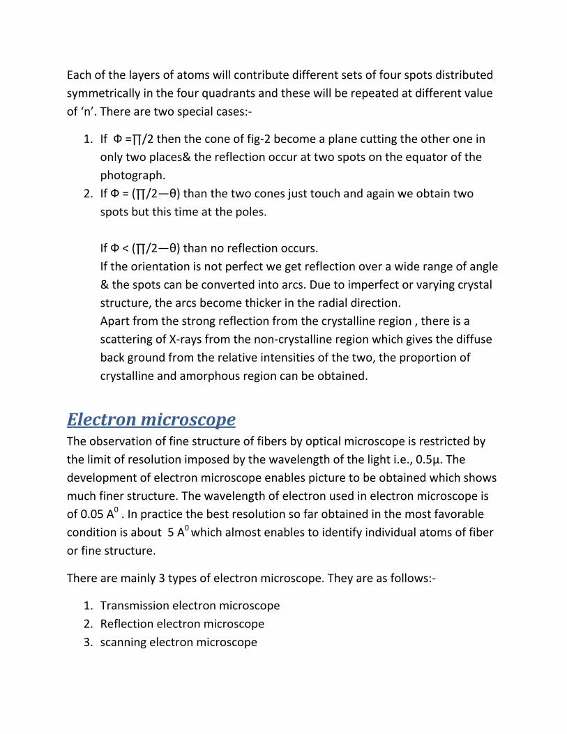
Transmission electron microscope
The ray from the electron source are condensed on the specimen and then
focused by electric or magnetic fields acting as lenses to give a magnified image
on a fluorescent screen or photographic plate. For the passage of electrons, it is
necessary for the instrument to be evacuated. Only dry specimen can be
examined. Contrast in the image depends on the variation on the scatterings of
the electrons by the parts of the specimen of different density. The unscattered
electrons are focused on the screen. The scattered electrons, which have lost
their energy and slowed down, would come to focus at a different point. They
form a diffuse background to a picture so reducing the contrast.
In principle, the electron microscope is similar to the optical microscope. The
electron beam is analogous to the ray of light where magnetic or electric fields
are similar to optical lenses. On major advantage of electric lenses is that they can
be continuously varied by varying the current but magnetic lenses are more
preferable because there is no danger of high voltage as in case of electric lenses.
One condition is provided in case of using the specimen in transmission electron
microscope that the specimen should be very thin i.e. less than 0.1µ which allows
the passage of electron.
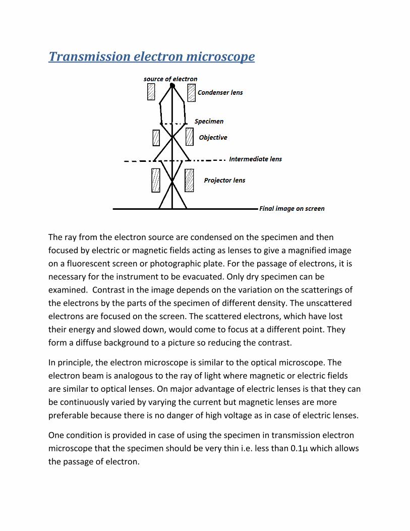
Reflection electron microscope
This is useful for the direct examination of surface of materials against indirect
method of replica technique used in the transmission electron microscope. The
elements of this microscope are the same as that of the transmission type but the
illuminating system (electron beam) is inclined at small angle ‘α’ (which generally
lies between 80-150) to the axis of the instrument. The specimen which is not
much thin is arranged with its surface at an angle ‘β’ such that α>β>α/2. The
image is formed by objective and projector lenses system from electrons
scattered or reflected from the specimen surface into the objective aperture.
A thin layer or sliver is evaporated on to the specimen so as to make it conductive
and prevent accumulate of charge. The magnification in the direction
perpendicular to the plane of a incidence is much greater than that right angles to
parallel, but because of great depth of focus of image a considerable length of
fiber is in focus and it helps in evaluating the shape and surface characteristics. A
serious drawback of this method is that the possibility of fiber damage by electron
bombardment.
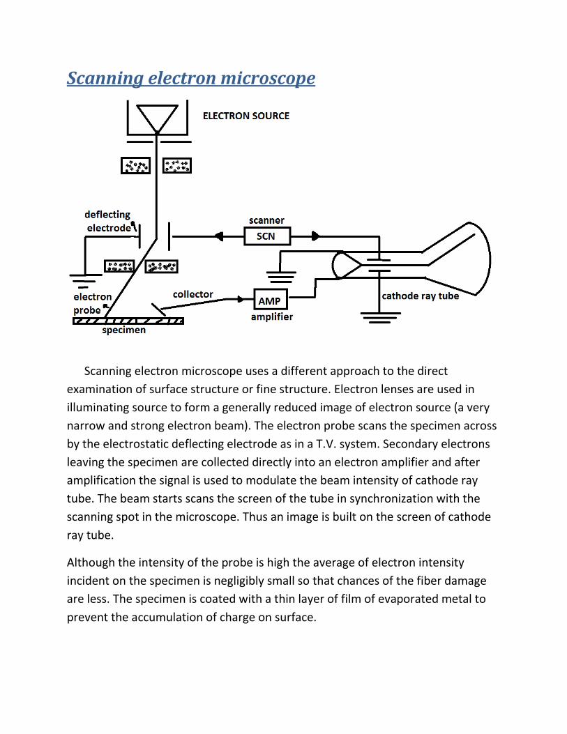
Scanning electron microscope
Scanning electron microscope uses a different approach to the direct
examination of surface structure or fine structure. Electron lenses are used in
illuminating source to form a generally reduced image of electron source (a very
narrow and strong electron beam). The electron probe scans the specimen across
by the electrostatic deflecting electrode as in a T.V. system. Secondary electrons
leaving the specimen are collected directly into an electron amplifier and after
amplification the signal is used to modulate the beam intensity of cathode ray
tube. The beam starts scans the screen of the tube in synchronization with the
scanning spot in the microscope. Thus an image is built on the screen of cathode
ray tube.
Although the intensity of the probe is high the average of electron intensity
incident on the specimen is negligibly small so that chances of the fiber damage
are less. The specimen is coated with a thin layer of film of evaporated metal to
prevent the accumulation of charge on surface.
Specimen preparation For getting proper contrast of image of the specimen or fine structure by electron
microscope, we have to use the test specimen very thin. Since the fibers are
mainly composed of lighter atoms they scattered the electrons to a lesser extent
so that many of the scattered electrons reach the screen there by reducing the
contrast. Improving contrast is one of the main problems in electron microscope.
Supporting films As in the case of t5he optical microscope the specimen is held on a glass plate
which is transparent to light. We need supporting films in electron microscope
which do not scatter electrons but are strong enough to support the specimen.
Generally colloidal or framework film are used. The films are prepared by
dissolving this substance in a volatile solvents and spreading the solution either
on a water surface or glass plate. The thickness is in the range of 100Ao. for the
high resolution work carbon films are used which are prepared by evaporating a
thin film of carbon on a substance which is subsequently dissolved away.
Shadow casting The contrast may be increased by evaporating on to the surface of the specimen
or by thin coating of a suitable metal at a small angle. The metals used are
paradium alloy of gold and palladium, chromium or platinum, since these metals
have high atomic weight their scattering power is much more and hence they
improve the contrast. The metal is evaporated in vacuum in such an angle that
the shadow to object ratio is about 4:1. Knowledge of shadow angle and the
length of shadow enable the height of the specimen above the supporting
membranes to be determined.
Thinner section Section for the examination in the electron microscope should be thinner than
0.1µ and some time they should be only a few hundred A0 thick. Special section
machine called “microtome” are available for this purpose. Since fibers are
flexible a hard embedding medium is necessary during section cutting. The
material is embedded in a mixture of butyl& methyl Meta crystal monomers
which is than polymerized, epoxy resins are also used for this purpose. The
forward movement of specimen on the microtome which is equal to the thickness
read is obtained by the thermal expansions of a metal rod to ensure smooth and
regulate movement. Steel glass and diamond knives are used for this section
cutting.
One of the limitations of this section is that some of the features observed may be
a result of the section cutting.
Disintegration method This method overcomes the difficulties involved in the section cutting but they
provide a different type of information. Fibers may be disintegrated into small
fragments by mechanical action (grinding), irradiation with ultrasonic’s,
dissolution by chemicals or enzymatic attack or by a combination of these
techniques. The suspension of a disintegration product in a suitable liquid
(generally water) is placed on a membrane coated grid and the liquid is allowed to
evaporate. The particles from the suspension dry down on to the supporting film
and are usually shadow cast to increase contrast. With this technique the fibril
structure of cellulosic and fibers can be clearly visible and identified.