Embed Size (px)
Citation preview
4504 Journal of The Electrochemical Society,146 (12) 4504-4513 (1999)S0013-4651(99)01-100-3 CCC: $7.00 © The Electrochemical Society, Inc.
Dow
Investigation of Electrocodeposition Using a Rotating Cylinder ElectrodeJean L. Stojaka and Jan B. Talbot*
Chemical Engineering Program, University of California, San Diego, La Jolla, California 92093-0411, USA
A rotating cylinder electrode was used to study the electrocodeposition of composite films containing alumina particles in a cop-per matrix. Deposition conditions ranging from kinetically controlled through mass-transfer limitation were investigated. Theeffects of hydrodynamics, particle loading in suspension, particle characteristics (size and crystallographic phase), as well as elec-trode orientation, were studied. Particle incorporation was analyzed using a precise, reproducible electrogravimetric technique.© 1999 The Electrochemical Society. S0013-4651(99)01-100-3. All rights reserved.
Manuscript submitted January 29, 1999; revised manuscript received August 11, 1999.
t
he
nn
eo
y
o
o
c-f angele
sit-tra-de-d toa
hasthe
ectm-
atethisherhel of
they-
-
ro-e-
r-fil-sed ofly-n
ua-ic
r-u-ric
ateereE)the
of
re
Electrocodeposition is a process in which metal matrix compite films are obtained by electroplating from a suspension of smparticles which are codeposited with the plated metal. The advtages of electrocodeposition over other coating methods are theformity of deposition for complex shapes, reduction of waste ofencountered in dipping or spraying techniques, low levels of conmination, and the ability to process parts continuously.1-4 In addi-tion, this process avoids problems associated with high temperaand vacuum processes, such as with sputtering and chemical vdeposition.
A wide range of composite films have been used for a varietyapplications by tailoring the composition via electrocodepositioFor example, these films have been used to protect against abraoxidation, and hot corrosion; to provide lubrication; or to createhigh hardness surface for cutting or grinding tools.3-9 The electro-codeposition process has been used to make dispersion-strengtalloy components9 and high surface area cathodes which have bused as electrocatalysts for hydrogen electrodes in industrial welectrolysis.10
Particles of carbides, oxides, polymers, and industrial diamowith diameters ranging from 2 to 100 mm have been embedded ielectroplated metals.1-9 The metals that have been used to form tmatrix of the composite films include gold, silver, copper, iron, nicel, cobalt, chromium, and their alloys. Metallic particles also habeen codeposited within an electroplated metal matrix. These mmetal composite films can then be heat-treated to form alloy cpositions, such as stainless steel.1
Film thickness can range from several microns up to a few mlimeters and is most often controlled by adjusting the deposittime. The amount of particle incorporation in the composite fidepends on the particle-matrix system of interest. For electrolwithout bath additives, incorporation levels typically range from 10 vol %. This level of incorporation requires a concentration of pticles suspended in the plating bath ranging from 2 to 200 depending on the desired composition of the film.3,9,11-19As muchas 50 vol % of particles has been incorporated into a compositewhen the particles were allowed to settle while plating onto a hzontal electrode.12 However, bath agitation typically is used to keethe particles in suspension. Incorporation levels as high as 70 vhave been reported without the aid of sedimentation, but requireduse of surfactants.4
While a significant amount of research has been conductedelectrocodeposition, most of the work has focused on maximizparticle incorporation or improving a specific property of the codposited film rather than understanding the process. The improvemof a specific film property is related to the particular application,i.e.,better corrosion or oxidation resistance, lower wear rates, and oall increase in the longevity of the coating. Despite its narrow focthe research to date has helped to identify important parameter
a Present address: Composite Optics, Inc., San Diego, CA 92121.* Electrochemical Society Active Member.
address. Redistribution subject to ECS 134.208.103.160nloaded on 2014-04-08 to IP
os-allan- uni-enta-
tureapor
ofn.sion, a
enedenater
ds
hek-vetal-m-
il-ionlmtes1-ar-g/L
filmri-
pl % the
oninge-ent
ver-us,s in-
volved in the electrocodeposition mechanism.9,11-19 These includehydrodynamics, current density, bath composition, particle charateristics, and particle loading in the suspension. The influence oparticular variable on the process is typically assessed by the chain the amount of particle incorporation obtained when that variabis adjusted.
While the effects of each of the process variables on the depoed film have been reported in the literature, results are often condictory and thus, it is uncertain how these variables affect the coposited film. For instance, while alpha alumina has been observereadily codeposit into copper films, the ability to codeposit gammalumina is debated. Even in the cases where gamma aluminabeen incorporated, the amount is about ten times less than amount obtained with the alpha phase.12,14,16,20
Some of the contradictions reported in the literature are a dirconsequence of uncontrollable, hence incomparable, hydrodynaics. The bulk of experimental electrocodeposition research to dwas conducted using a vertical parallel plate electrode setup. In configuration, the particles are maintained in suspension by eitstirring the solution, vibrating a perforated plate at the bottom of tcell, bubbling gas, or pumping the suspension through the cell, alwhich result in incomparable hydrodynamics.
Several analytical methods that have been used to determineparticle concentration in the deposit include: gravimetric analsis,18,20,21 X-ray fluorescence,19 atomic absorption spectros-copy,14,22-24 and microscopic analysis using optical light microscopy15,25 or scanning electron microscopy (SEM).26,27 In all of thepublished data, there is little discussion of the accuracy or repducibility of the analytical technique used for determining the corrsponding matrix and particle composition.28,29
While gravimetric analysis is a good technique when larger paticles are involved, it was not considered as the readily available ters were too coarse for the separation of the smaller particles uin this study. Three other analytical methods for the determinationthe amount of particle incorporation were considered for the anasis of the electrocodeposited films in this work: atomic absorptiospectroscopy, microscopic evaluation, and electrochemical evaltion.30 However, the accuracy of atomic absorption spectroscopmethod of 61-3 wt % particle incorporation was insufficient for thisstudy. Although analysis by SEM was useful for confirmation of paticle incorporation, it was found to be too problematic to yield accrate particle incorporation data. Therefore, an electrogravimetevaluation method was developed.
Using a reproducible experimental procedure and an accurmethod for determining the amount of particle incorporation, theffects of various process variables on the film composition weevaluated. For this investigation, a rotating cylinder electrode (RCconfiguration was chosen and optimally designed, as it provided best control of the hydrodynamics.30 With this system, electrocode-position experiments were conducted over the complete rangedeposition conditions,i.e., from kinetically controlled through mass-transfer limitation of electrocodeposition. Polarization scans we
) unless CC License in place (see abstract). ecsdl.org/site/terms_useterms of use (see
Journal of The Electrochemical Society,146 (12) 4504-4513 (1999) 4505S0013-4651(99)01-100-3 CCC: $7.00 © The Electrochemical Society, Inc.
o
a
e
d
f
e
ac
o
c
e
i
ater the sur-
positis-
ri-
lec-nce).uterry in
rentsi- arear-is-ssen- theow-
htnges not
the
Dow
conducted using this system to optimize the bath composition, alling the full range of deposition to be studied without the complictions due to the onset of hydrogen evolution.30 The optimized bathcomposition was determined to be 0.1 M CuSO4 1 1.2 M H2SO4.
Alumina was the particle of choice since it is readily availablemonodispersed sizes and different crystallographic phases (e.g.,alpha, gamma,and theta) with which to address the controversy cocerning the effect of particle phase on codeposition. Additional matransfer studies identified the limiting current density as a functionparticle loading in suspension and electrode rotational rate.30 Alphaalumina particle loadings at or below 120 g/L had little or no affeon the mass-transfer limiting conditions. However, particle loadinof 158 g/L were found to increase the limiting current density bymuch as 32%. In addition to raising the limiting current density, t158 g/L particle loading significantly lowered the current density vues in the kinetically controlled region.
Experimental
RCE electrochemical cell.—The electrochemical cell housingused in this study was a 200 mL glass cylinder with a separate chber for the reference electrode. Two different cathode-anode orietions were used for the electrochemical system. Both orientatiinvolved a rotating cylindrical electrode positioned in the centerthe cell with a stationary cylindrical electrode concentric to the cter electrode and located against the cell wall. The electrodes walso centered with respect to each other,i.e., the midheight of theelectrodes were on the same horizontal plane.
The first orientation utilized the inner rotating cylinder as thcathode,with the concentric outer stationary cylinder as the anoas shown in Fig. 1. The inner rotating electrode with a Teflon encsulated rotating shaft was a removable stainless steel cylinmachined to a diameter of 12 and 8 mm in height. The surface orotating cylinder electrode was recessed slightly from the Teflon sfaces above and below it, in order to reduce the effect of the curdiscontinuity at the electrode edges.
Oxygen-free high-conductivity (OFHC) copper foil was used tmake the stationary outer cylindrical anodes. The stationary anopositioned flush against the inside of the cell wall to minimize flodisturbance, was 9 mm high with an inner radius of 24 mm. Insulaing tape was used to cover the outside surface of the cylindrical anfoil, as well the submerged portion of the anode’s electrical conntion and support, which was also positioned flush against the cell w
A saturated calomel electrode (SCE) was used as the referelectrode, which was placed in a separate compartment connectthe electrochemical cell via a Luggin capillary. Typically, a Luggcapillary is extended close to the surface of the working electroHowever, flow visualization experiments conducted with dye indcated that when the capillary was extended toward the inner rotacylinder,the flow around the RCE was disrupted. Therefore, the cillary was positioned flush with the cell wall to minimize disturbanto the flow, as shown in Fig. 1.
The second configuration is similar to that shown in Fig. 1; hoever, the polarization was reversed, making the outer stationcylinder the cathode. A stainless steel ring machined to an indiameter of 2.4 cm with a height of 4 mm was used as the cathA thin coating of an insulating polymer was applied to the outer sface of the cathode and on the submerged portion of the stainsteel rod used to support the cathode ring and to connect to the electrical leads.
The anodes which were initially used as the RCE were machifrom OFHC copper and prepared for the plating experiments in same manner as the stationary anodes. OFHC copper was chosthe anode material due to its high quality and ability to electchemically dissolve uniformly. Copper anodes made from lowequality material tend to form loose particles in the electrolyte whcould collect on the cathode and cause dendrite formation.31 How-ever,it was determined that anodes prepared by plating copper ostainless steel RCEs gave the same results as OFHC copper 30; there-fore,both substrates were used.
address. Redistribution subject to ECS 134.208.103.160nloaded on 2014-04-08 to IP
w-a-
in
n-ss- of
ctgsashel-
am-nta-onsofn-ere
ee,
ap-der, theur-rent
ode,wt-odeec-all.nce
ed toinde.i-tingp-e
w-arynerde.
ur-lessell’s
nedthen for
ro-rch
nto
The height of the outer anode was chosen to be slightly grethan the rotating cathode for ease of alignment. The height ofouter cathode was constrained due to weight considerations andface area. If the weight of the cathode is large relative to the deweight, the error involved in the analysis of the deposit, to be dcussed, would be excessive.
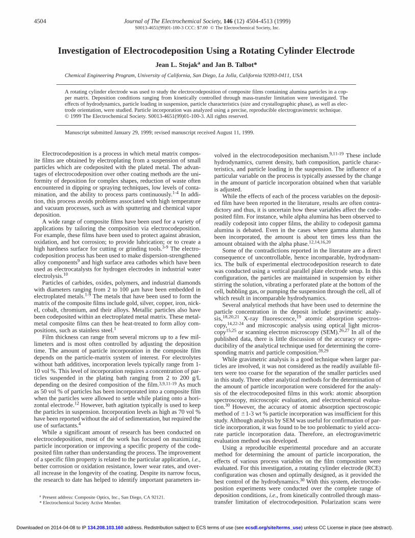
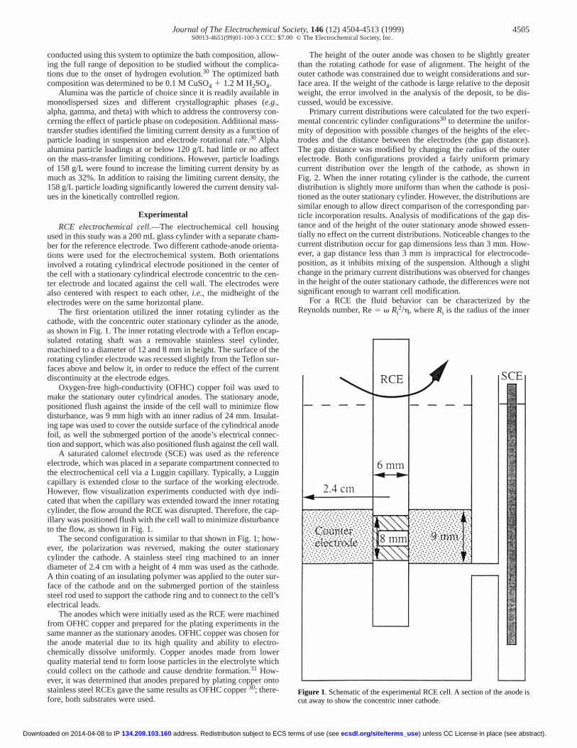
Primary current distributions were calculated for the two expemental concentric cylinder configurations30 to determine the unifor-mity of deposition with possible changes of the heights of the etrodes and the distance between the electrodes (the gap distaThe gap distance was modified by changing the radius of the oelectrode. Both configurations provided a fairly uniform primacurrent distribution over the length of the cathode, as shownFig. 2. When the inner rotating cylinder is the cathode, the curdistribution is slightly more uniform than when the cathode is potioned as the outer stationary cylinder. However, the distributionssimilar enough to allow direct comparison of the corresponding pticle incorporation results. Analysis of modifications of the gap dtance and of the height of the outer stationary anode showed etially no effect on the current distributions. Noticeable changes tocurrent distribution occur for gap dimensions less than 3 mm. Hever,a gap distance less than 3 mm is impractical for electrocode-position,as it inhibits mixing of the suspension. Although a sligchange in the primary current distributions was observed for chain the height of the outer stationary cathode, the differences weresignificant enough to warrant cell modification.
For a RCE the fluid behavior can be characterized by Reynolds number, Re 5 vRi
2/h, where Ri is the radius of the inner
Figure 1. Schematic of the experimental RCE cell. A section of the anode iscut away to show the concentric inner cathode.
) unless CC License in place (see abstract). ecsdl.org/site/terms_useterms of use (see
4506 Journal of The Electrochemical Society,146 (12) 4504-4513 (1999)S0013-4651(99)01-100-3 CCC: $7.00 © The Electrochemical Society, Inc.
-
c
o
c
aa
e
edtn
Da
ntco
sb
l.
ich
par-asn anm-
after
ndhedgsnen
ndpm.l
den-rentom-ingrom
sit,
epro-he theee
by
e(upesshefilm
in wast of
ndeel is steelde-
ero-unt ap-eas-Thedyta-osi-
of
red.tingn of
h
Down
rotating cylinder,v is rotational speed of the cylinder (rad/s), and his the kinematic viscosity.32 The onset of turbulence occurs at a critical Re between 100 and 200. This means that the flow in a conctric RCE cell is generally turbulent. Laminar flow in a concentricylinder configuration is not of much practical interest, since thflow moves in concentric circles without enhancement to the ratemass transfer.33 In a narrow region between laminar and turbulenflow conditions, concentric cylindrical flow experiences a phenomenon referred to as Taylor vortices. Since both electrode orientatiused for the electrocodeposition experiments used a 6 mm radrotating cylinder, the onset of turbulence occurs at a rotational rateof 60 rpm. In order to maintain adequate mixing of the particledepositions were conducted only in turbulent flow.
Deposition experiments.—All deposition experiments were con-ducted using a three-electrode system consisting of a RCE, a contric stationary electrode, and a SCE as a reference. An EG&G Printon Applied Research potentiostat/galvanostat model 273 was used tocontrol the current (or voltage) and to monitor the correspondinvoltage (or current) during the depositions. The current and voltameasurements were recorded using a computer data acquisition stem. The data was first collected in the buffer of a Hewlett-Packa(HP 7090) plotter and then down-loaded to an IBM XT personcomputer. The RCE was rotated using a Pine Instrument CompASR 589 analytical rotator. The rate was adjusted using the rotacontroller until the desired rotational rate was obtained and confirmusing a light-emitting diode (LED)-oscilloscope system.30
All glassware was first cleaned in a solution of sulfuric acidnitric acid, and distilled deionized (DDI) water with a 4:2:1 volumratio. This was followed by five thorough rinses with deionizewater before a final rinse with DDI water. The stainless steel caodes were polished to a 1 mm finish using a slurry of alpha-alumiin DDI water and then buffed using Wenol® polish. The cathodeswere degreased by soaking in methanol for 30 min, rinsed with Dwater,and then soaked in isopropanol for 30 min. Just prior to experiment,the cathode was soaked in 0.1 M sulfuric acid for 5 minrinsed in DDI water, and dried using an inert gas (nitrogen or argo
The anodes machined from OFHC copper were prepared for plating experiments in the same manner as the cathodes. The setype of RCE copper anodes were made just prior to each codeption experiment by plating copper onto the stainless steel RCThese anodes were removed from the copper plating bath, rinwith DDI water, dried using an inert gas, and immediately sumerged into the electrolyte.
Fresh electrolyte was prepared for each experiment using reaggrade sulfuric acid and copper sulfate. The solutions were th
Figure 2. Comparison of primary current distribution for the two RCE configurations. The ratio of current density at a certain cylinder height to theight-averaged current density,i/iavg, is plotted vs. the normalized height(X/L) from bottom (X 5 0) to top (X 5 L) of the cathode.
address. Redistribution subject to ECS te134.208.103.160loaded on 2014-04-08 to IP
en-
eoft-nsius
s,
en-ce-
ggeys-rdlnytord
,
h-a
In,).
heondsi-
E.ed-
enten
passed through a 0.2 mm filter to remove any suspended materiaThe pH was adjusted to a value of 0.30 6 0.01 using sulfuric acid.The pH was measured using an Orion model 5A720 pH meter whwas calibrated prior to each set of measurements.
Suspensions were prepared by adding a specified weight of ticles to 200 mL of solution in a 250 mL beaker. The mixture wcovered and stirred using a magnetic stirrer for 12-24 h, placed iultrasonic bath for 15 min, and cooled to room temperature. Teperature and pH of the suspensions were recorded before andeach experiment.
Conductivity was recorded for all suspensions just prior to aimmediately after each experiment until the values were establisfor each particle loading and particle composition. A Yellow SprinInstrument (YSI) conductivity probe, model 3401, in conjunctiowith a YSI conductivity meter, model 34, was calibrated and thused for these measurements.
Galvanostatic depositions with a rotating cylinder cathode wereconducted as a function of particle loading (3.9, 20, 39, 120, a158g/L) at three electrode rotational rates: 500, 1000, and 1500 rGalvanostatic deposition was utilized since it provided better controthan was possible under potentiostatic conditions. The current sities investigated ranged between 5 and 90% of the limiting curdensity. Each parameter set was defined by a particular particle cposition, particle loading, and electrode rotational rate. The limitcurrent density for each set of experiments was determined fpolarization scans.30
Due to the number of variables which affect the resulting depoa minimum of three separate experiments,conducted on separatedays, for each parameter set were completed to establish the rducibility of the results. The amount of particle incorporation, tdetermination of which is discussed, was the basis for evaluatingexperiments. If the amount of particle incorporation of the threxperiments for each parameter set were not all within 60.5 wt % ofeach other, additional experiments were conducted.
The galvanostatic deposition experiments were conductedadjusting the time of deposition to obtain 15-30 mm thick deposits.It was determined that the 15 mm thick deposits provided the samrelative amounts of particle incorporation as the thicker deposits to 30 mm thick) over the range of parameters investigated. Films lthan 15 mm thick were not appropriate since the relative error in tamount of particle incorporation increased as the weight of the decreased due to the weight of the cathode itself.
Galvanostatic deposition experiments were also conducted which the cathode was the outer stationary cylinder and the RCEthe anode. Composite films of 15 mm thickness were deposited a1500 rpm with 120 g/L particle loading in suspension as a functioncurrent density from 10 to 90% of the limiting current density.
After each deposition, the cathode was removed from the platingbath, thoroughly rinsed with DDI water, dried using an inert gas, aweighed. Since the adhesion of copper coatings on stainless stvery poor, the copper-based deposit was peeled off the stainlesscathodes, allowing them to be used repeatedly. The removed coposited films could be analyzed further.
Determination of particle incorporation.—To determine thamount of particle incorporation, an electrogravimetric analysis pcedure was developed following Faraday’s law, relating the amoof copper electrodeposited to the total charge passed. In thisproach,the number of coulombs passed during deposition was mured by a coulometer, which is internal to the galvanostat used. efficiency of copper deposition using the sulfate bath of this stuwas evaluated from 10 to 90% of the limiting current for each rotional rate with the cathode in both the rotating and stationary ptions. In all cases, the current efficiency was 100% (60.2%, withinthe accuracy of the calibrated Sartorius model 1712 MP860.2 mg). Thus,the amount of copper that was electrodepositedduring codeposition was calculated from the total charge measuThe amount of particle incorporation was determined by subtracthe calculated amount of copper deposited from the weight gai
-e
) unless CC License in place (see abstract). ecsdl.org/site/terms_userms of use (see
Journal of The Electrochemical Society,146 (12) 4504-4513 (1999) 4507S0013-4651(99)01-100-3 CCC: $7.00 © The Electrochemical Society, Inc.
.1 %
gof
wm tmt
s
Th
a
wfr-
tu
cdn
etot hwin
-tt
d
05ic
esrea
ds of toofpmnt oftheThengusly ofnd
mi- par-
at- for
a
clesrre-
poth-bedt
ad-
ota-
Dow
the cathode. The typical weight of the codeposited films were 0resulting in an accuracy in the particle incorporation of 60.2 wtThis technique was used for film thicknesses of 15 and 30 mm andthe results were found to be within the accuracy of the scale.
Particle characterization.—Electron microscopy.—Scanninelectron microscopy (SEM) and transmission electron microsc(TEM) were used to observe the size and surface features o0.05 mm gamma alumina and the 0.3 mm alpha alumina powdused in the electrocodeposition experiments. The SEM samplesprepared by applying an adhesive tape to a standard SEM sastub and pressing the adhesive side of the stub into the powderanalyzed. Excess powder was removed by gently tapping the sastub. The remaining powder was coated with gold prior to inserinto the SEM for observation.
The powders were also evaluated using TEM to observe thefaces of the individual particles. The alumina powders were pended in ethanol, mixed, and placed in an ultrasonic bath priodepositing onto standard TEM specimen grid via a pipette. ethanol evaporated, leaving the particles to electrostatically adonto the grid. Prior to coating with the particle suspensions, the sple grids were degreased in methanol and isopropanol and etched in 0.5 M sulfuric acid, rinsed in distilled deionized water,dried using an inert gas (argon or nitrogen).
X-ray diffraction.—The X-ray diffraction scans of the alumina poders used in this study were obtained using a Scintag X-ray diftion unit. The scan rate used for the 0.3 mm and larger alumina powders was 18/min over the theta range of 15-1208. For the 0.05mmgamma alumina powders an X-ray scan rate of 0.508/min over thetheta range of 15-1208 was used. A slower scan rate was used forgamma phase due to the smaller particle size, which prodbroader peaks and required a longer count time at each angle toimize the background noise.
Density.—Density measurements of the powders were conduusing Archimedes’ principle. Average weights of the clean,10 mL volumetric flask and stopper and the flask filled with deioized distilled water at 228C with the stopper in place were measuThe volume within the flask and stopper was determined fromweight of the water in the flask and the density of water at this tperature,0.9977 g/cm3. 34 From the weight of the powder added the flask and the weight of the water needed to finish filling flask, the corresponding volume of the water and powder coulddetermined, providing the necessary information to calculate tdensity of the powder. The weights of the water and the powder the water were obtained after evacuating the dissolved air usNalgene® sink-based aspirator.
Results and DiscussionRotating cathode experiments.—The first stage of the investiga
tion was the electrocodeposition of composite films on the inner rotaing cathode. Depositions were conducted as a function of parloading in suspension, electrode rotational rate, current density,size and crystallographic phase of the alumina particles. The gamphase particles were used first since this was the smallest sizemina powder available,0.05 mm diam supplied by Buehler, Ltd.
Particle loading.—Preliminary experiments were conductedparticle loadings of 3.9, 19.5, and 39 g/L (corresponding to 0.1,and 1.2 vol % in solution) at three electrode rotational rates (1000,1500 rpm) for several different current densities. When usless than 39 g/L particle loading in suspension, the amount of inporation was less than 0.2 wt %, which was the detection limit ofanalytical method used in this investigation. However, the amounparticle incorporation obtained with 39 g/L loading of particlessuspension was just at the lower limit of reliable detection. Thfore, codeposition experiments were conducted using 39 g/L (aminimum particle loading), 120, and 158 g/L loadings, which corspond to 1.2, 3.5, and 4.6 vol % of particles suspended in the trolyte. Settling of particles became a problem with loadings grethan 158 g/L.
address. Redistribution subject to ECS 134.208.103.160nloaded on 2014-04-08 to IP
g,.
py theersereple
o beple
ing
sur-us-r toheere
am-thennd
-ac-
hecedmin-
tedry-
red.them-
hebeeithg a
-icleandma- alu-
at.5,00,ngor-
thet ofinre- thee-lec-ter
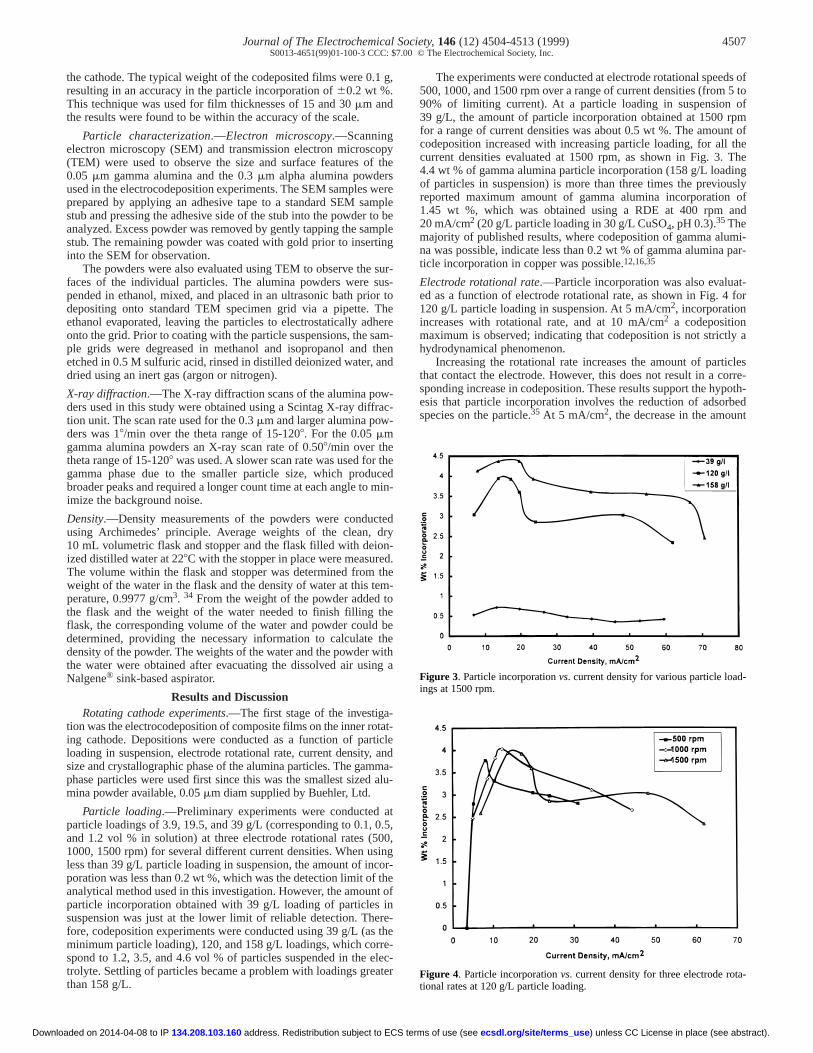
The experiments were conducted at electrode rotational spee500, 1000,and 1500 rpm over a range of current densities (from 590% of limiting current). At a particle loading in suspension 39 g/L, the amount of particle incorporation obtained at 1500 rfor a range of current densities was about 0.5 wt %. The amoucodeposition increased with increasing particle loading, for all current densities evaluated at 1500 rpm, as shown in Fig. 3. 4.4wt % of gamma alumina particle incorporation (158 g/L loadiof particles in suspension) is more than three times the previoreported maximum amount of gamma alumina incorporation1.45 wt %, which was obtained using a RDE at 400 rpm a20 mA/cm2 (20 g/L particle loading in 30 g/L CuSO4, pH 0.3).35Themajority of published results, where codeposition of gamma aluna was possible, indicate less than 0.2 wt % of gamma aluminaticle incorporation in copper was possible.12,16,35
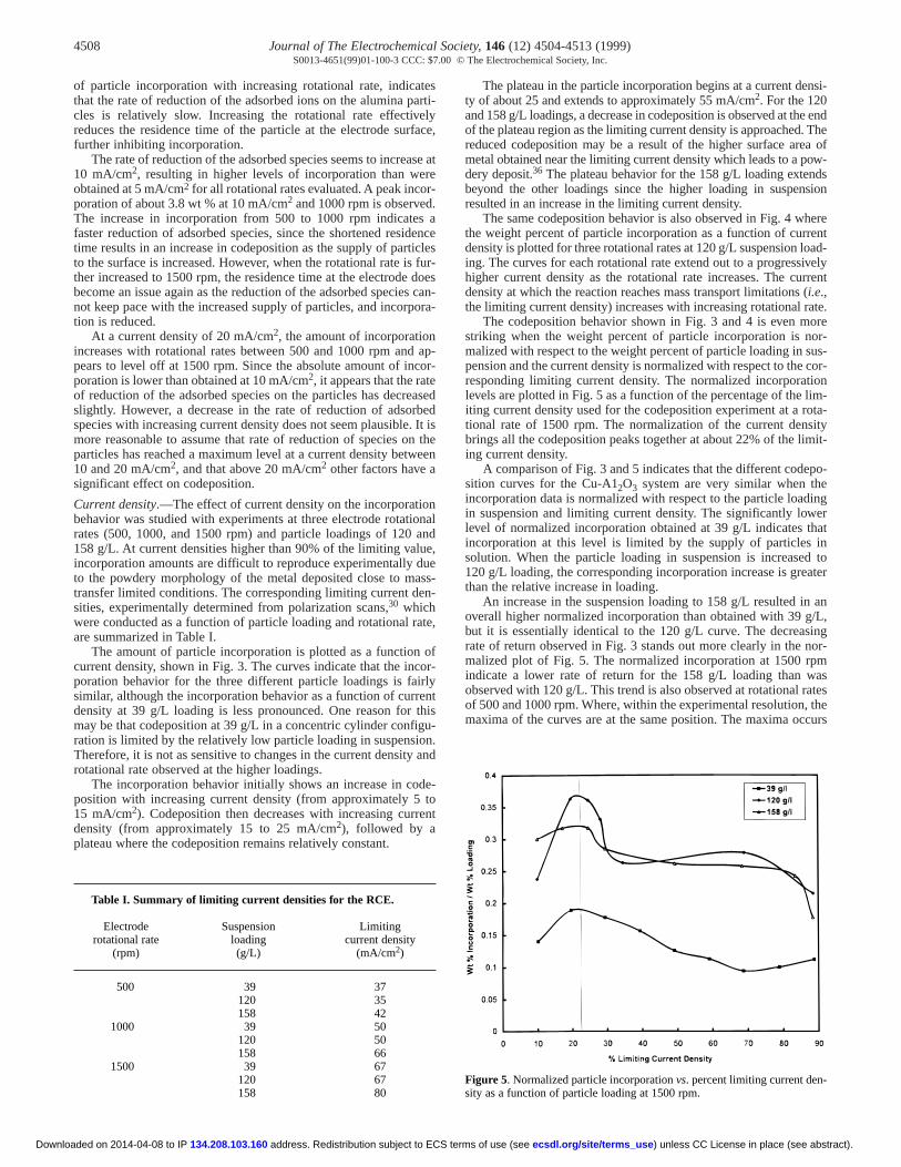
Electrode rotational rate.—Particle incorporation was also evalued as a function of electrode rotational rate, as shown in Fig. 4120 g/L particle loading in suspension. At 5 mA/cm2, incorporationincreases with rotational rate, and at 10 mA/cm2 a codepositionmaximum is observed; indicating that codeposition is not strictlyhydrodynamical phenomenon.
Increasing the rotational rate increases the amount of partithat contact the electrode. However, this does not result in a cosponding increase in codeposition. These results support the hyesis that particle incorporation involves the reduction of adsorspecies on the particle.35 At 5 mA/cm2, the decrease in the amoun
Figure 3. Particle incorporation vs. current density for various particle loings at 1500 rpm.
Figure 4. Particle incorporation vs. current density for three electrode rtional rates at 120 g/L particle loading.
) unless CC License in place (see abstract). ecsdl.org/site/terms_useterms of use (see
4508 Journal of The Electrochemical Society,146 (12) 4504-4513 (1999)S0013-4651(99)01-100-3 CCC: $7.00 © The Electrochemical Society, Inc.
f
r.
s
b
n
i
a
r
e
nsi-
e endThefow-dssion
hereentoad-ivelyrrent(ate.oreor-us- cor-ionlim-ota-sitymit-
po-einger
hatin
d toater
an/L,ingnor-mastesthecurs
n-
Dow
of particle incorporation with increasing rotational rate, indicatthat the rate of reduction of the adsorbed ions on the alumina pcles is relatively slow. Increasing the rotational rate effectivereduces the residence time of the particle at the electrode surfurther inhibiting incorporation.
The rate of reduction of the adsorbed species seems to increa10 mA/cm2, resulting in higher levels of incorporation than werobtained at 5 mA/cm2 for all rotational rates evaluated. A peak incoporation of about 3.8 wt % at 10 mA/cm2 and 1000 rpm is observedThe increase in incorporation from 500 to 1000 rpm indicatesfaster reduction of adsorbed species, since the shortened residtime results in an increase in codeposition as the supply of partito the surface is increased. However, when the rotational rate isther increased to 1500 rpm, the residence time at the electrode become an issue again as the reduction of the adsorbed specienot keep pace with the increased supply of particles, and incorption is reduced.
At a current density of 20 mA/cm2, the amount of incorporationincreases with rotational rates between 500 and 1000 rpm andpears to level off at 1500 rpm. Since the absolute amount of incporation is lower than obtained at 10 mA/cm2, it appears that the rateof reduction of the adsorbed species on the particles has decreslightly. However, a decrease in the rate of reduction of adsorspecies with increasing current density does not seem plausible.more reasonable to assume that rate of reduction of species oparticles has reached a maximum level at a current density betw10 and 20 mA/cm2, and that above 20 mA/cm2 other factors have asignificant effect on codeposition.
Current density.—The effect of current density on the incorporatbehavior was studied with experiments at three electrode rotationalrates (500, 1000, and 1500 rpm) and particle loadings of 120 158 g/L. At current densities higher than 90% of the limiting valuincorporation amounts are difficult to reproduce experimentally dto the powdery morphology of the metal deposited close to matransfer limited conditions. The corresponding limiting current desities, experimentally determined from polarization scans,30 whichwere conducted as a function of particle loading and rotational rare summarized in Table I.
The amount of particle incorporation is plotted as a functioncurrent density, shown in Fig. 3. The curves indicate that the incporation behavior for the three different particle loadings is faisimilar,although the incorporation behavior as a function of curredensity at 39 g/L loading is less pronounced. One reason for may be that codeposition at 39 g/L in a concentric cylinder configu-ration is limited by the relatively low particle loading in suspensioTherefore,it is not as sensitive to changes in the current density arotational rate observed at the higher loadings.
The incorporation behavior initially shows an increase in codposition with increasing current density (from approximately 5 15 mA/cm2). Codeposition then decreases with increasing currdensity (from approximately 15 to 25 mA/cm2), followed by aplateau where the codeposition remains relatively constant.
Table I. Summary of limiting current densities for the RCE.
Electrode Suspension Limitingrotational rate loading current density
(rpm) (g/L) (mA/cm2)
500 39 37120 35158 42
1000 39 50120 50158 66
1500 39 67120 67158 80
address. Redistribution subject to ECS 134.208.103.160nloaded on 2014-04-08 to IP
esarti-lyace,
se ate-
aenceclesfur-does can-
ora-
ap-or-
aseded
It is theeen
on
ande,uess-n-
te,
ofor-lyntthis
n.nd
e-tont
The plateau in the particle incorporation begins at a current dety of about 25 and extends to approximately 55 mA/cm2. For the 120and 158 g/L loadings, a decrease in codeposition is observed at thof the plateau region as the limiting current density is approached. reduced codeposition may be a result of the higher surface area ometal obtained near the limiting current density which leads to a pdery deposit.36 The plateau behavior for the 158 g/L loading extenbeyond the other loadings since the higher loading in suspenresulted in an increase in the limiting current density.
The same codeposition behavior is also observed in Fig. 4 wthe weight percent of particle incorporation as a function of currdensity is plotted for three rotational rates at 120 g/L suspension ling. The curves for each rotational rate extend out to a progresshigher current density as the rotational rate increases. The cudensity at which the reaction reaches mass transport limitations i.e.,the limiting current density) increases with increasing rotational r
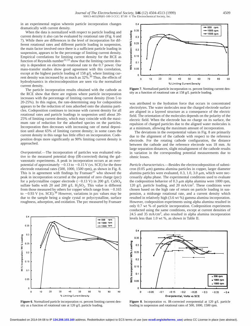
The codeposition behavior shown in Fig. 3 and 4 is even mstriking when the weight percent of particle incorporation is nmalized with respect to the weight percent of particle loading in spension and the current density is normalized with respect to theresponding limiting current density. The normalized incorporatlevels are plotted in Fig. 5 as a function of the percentage of the iting current density used for the codeposition experiment at a rtional rate of 1500 rpm. The normalization of the current denbrings all the codeposition peaks together at about 22% of the liing current density.
A comparison of Fig. 3 and 5 indicates that the different codesition curves for the Cu-A12O3 system are very similar when thincorporation data is normalized with respect to the particle loadin suspension and limiting current density. The significantly lowlevel of normalized incorporation obtained at 39 g/L indicates tincorporation at this level is limited by the supply of particles solution. When the particle loading in suspension is increase120g/L loading, the corresponding incorporation increase is grethan the relative increase in loading.
An increase in the suspension loading to 158 g/L resulted inoverall higher normalized incorporation than obtained with 39 gbut it is essentially identical to the 120 g/L curve. The decreasrate of return observed in Fig. 3 stands out more clearly in the malized plot of Fig. 5. The normalized incorporation at 1500 rpindicate a lower rate of return for the 158 g/L loading than wobserved with 120 g/L. This trend is also observed at rotational raof 500 and 1000 rpm. Where, within the experimental resolution,maxima of the curves are at the same position. The maxima oc
Figure 5. Normalized particle incorporation vs. percent limiting current desity as a function of particle loading at 1500 rpm.
) unless CC License in place (see abstract). ecsdl.org/site/terms_useterms of use (see
Journal of The Electrochemical Society,146 (12) 4504-4513 (1999) 4509S0013-4651(99)01-100-3 CCC: $7.00 © The Electrochemical Society, Inc.
s
.acf
ei
i
oy
v
g
(
t
br
tedrfaceectric the, thees is
rilyencence. At
sultse to
i-eternec-luate,
sus-ichon.d inntses ofn
e
n-
icle
Do
in an experimental region wherein particle incorporation chandramatically with current density.
When the data is normalized with respect to particle loadingcurrent density it also can be evaluated by rotational rate (Fig. 67). While there are differences in the level of incorporation for ferent rotational rates and different particle loading in suspenthe main factor involved once there is a sufficient particle loadinsuspension, appears to be the percentage of limiting current densEmpirical correlations for limiting current density for the RCE function of Reynolds number32,33show that the limiting current density is dependent on electrode rotational rate to the 0.7 powermass-transfer studies show good agreement with this correlexcept at the highest particle loading of 158 g/L where limiting rent density was increased by as much as 32%.30 Thus, the effects ohydrodynamics in electrocodeposition are seen via the normacurrent density.
The particle incorporation results obtained with the cathodthe RCE show that there are regions where particle incorporatincreases with the percentage of limiting current density (from 20-25%). In this region, the rate-determining step for codeposappears to be the reduction of ions adsorbed onto the alumina pcles. Codeposition continues to increase with current density forotational rates and particle loadings in suspension until abou25% of limiting current density, which may coincide with the mamum rate of reduction for the adsorbed species on the partIncorporation then decreases with increasing rate of metal detion until about 65% of limiting current density; in some casescurrent density in this range has little effect on incorporation. Cposition drops more significantly as 90% limiting current densitapproached.
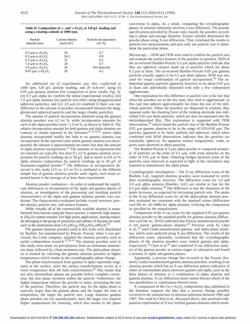
Overpotential.—The incorporation of particles was evaluated retive to the measured potential drop (IR-corrected) during thevanostatic experiments. A peak in incorporation occurs at an opotential of approximately 20.13 to 20.15 V (vs. SCE) for the thelectrode rotational rates (500, 1000, 1500 rpm), as shown in FiThis is in agreement with findings by Fransaer37 who showed thepeak in incorporation occurred at the potential of zero charge for a polycrstalline copper electrode (20.13 V) in 200 g/L CuS4sulfate baths with 20 and 200 g/L H2SO2. This value is differenfrom those measured by others for copper which range from 20to 20.93 V (vs. SCE).38 However, variations in pzc values may due to the sample being a single cystal or polycrystalline, suroughness, adsorption,and oxidation. The pzc measured by Frans
Figure 6. Normalized particle incorporation vs. percent limiting current dsity as a function of rotational rate at 120 g/L particle loading.
address. Redistribution subject to ECS134.208.103.160wnloaded on 2014-04-08 to IP
ges
and and
dif-ion,
g inity.as- Ourtion,ur-
lized
ason5 totionarti-r all
t 20-xi-icles.posi-thede- is
la-gal-er-ree. 8.
pzc)O
.165efaceaer
was attributed to the hydration force that occurs in concentraelectrolytes. The water molecules near the charged electrode suare aligned in a layered structure as a consequence of the elfield. The orientation of the molecules depends on the polarity ofelectric field. When the electrode has no charge on its surfacerepulsion of charged particles due to the aligned water moleculat a minimum, allowing the maximum amount of incorporation.
The deviations in the overpotential values in Fig. 8 are primadue to the alignment of the cathode with respect to the referelectrode. For the rotating cathode configuration, the distabetween the cathode and the reference electrode was 18 mmlarge separation distances, slight misalignment of the cathode rein variation in the corresponding potential measurements duohmic losses.
Particle characteristics.—Besides the electrocodeposition of submcron (0.05 mm) gamma alumina particles in copper, larger diamalumina particles were evaluated, 0.3, 1.0, 3.0 mm, which were cessarily alpha phase. The experimental conditions used to evathe codeposition behavior of 0.3 mm alpha alumina were 1000 rpm120 g/L particle loading, and 20 mA/cm2. These conditions werechosen based on the high rate of return on particle loading in pension,a midrange rotational rate, and a current density whresulted in relatively high (3.6 wt %) gamma alumina incorporatiHowever, codeposition experiments using alpha alumina resulteonly 0.7 wt % of particle incorporation. Codeposition experimeconducted using the same conditions, except at current densiti24.5 and 35 mA/cm2, also resulted in alpha alumina incorporatiolevels less than 1.0 wt %, as shown in Table II.
n-
Figure 7. Normalized particle incorporation vs. percent limiting current desity as a function of rotational rate at 158 g/L particle loading.
Figure 8. Incorporation vs. IR-corrected overpotential at 120 g/L partloading in suspension and rotational rates of 500, 1000, 1500 rpm.
) unless CC License in place (see abstract). ecsdl.org/site/terms_use terms of use (see
4510 Journal of The Electrochemical Society,146 (12) 4504-4513 (1999)S0013-4651(99)01-100-3 CCC: $7.00 © The Electrochemical Society, Inc.
3i
ae
n
tc
co
uueu
d
u
t
em
hicderrd-the toter-
zeM ofthatout
a
d
at, in
ndi-ey
ndi-heMirheenareor
ri-
thetep
efyndeeeaksw-tionn
c-er
mi-heicpha,
und
or- anofs thend
he
iblyand-
Down
An additional set of experiments was also conducted1000 rpm, 120 g/L particle loading, and 20 mA/cm2, using (i)0.05 mm gamma alumina (for comparison to prior results, Fig. (ii) 0.3 mm alpha (to confirm the initial experimental results), (ii)1.0 mm alpha alumina (for particle size effect using deagglomeraspherical particles), and (iv) 3.0 mm (to establish if there was difference in the amount of powders incorporated between the dglomerated spherical particles and the larger chunky particles).
The amount of particle incorporation obtained using the gamalumina powders was 4.2 wt %, while incorporation amounts each of the alpha powders were <1.0 wt %, as shown in Table II.relative incorporation amount for both gamma and alpha aluminacontrary to results reported in the literature12,14,16,20where alphaalumina incorporated readily but little to no gamma alumina wincorporated. In the reported cases where gamma alumina was iporated,the amount is approximately ten times less than the amoof alpha alumina incorporation.12 The amounts of incorporation thaare reported are typically less than 0.1 wt % gamma alumina inporation for particle loadings up to 30 g/L and as much as 8.8 walpha alumina codeposition for particle loadings up to 50 g/LSumitomo-supplied powder.18 The difference in incorporation ob-served in this study (3.6 vs. 4.2 wt %) is attributed to the differesample lots of gamma alumina powder used. Again, each result re-ported herein is the average of at least three experiments.
Alumina powder evaluation.—In order to understand the signcant differences in incorporation of the alpha and gamma phasealumina,an investigation of the processing and resulting particharacteristics of the alpha and gamma alumina powder was cducted. The characteristics evaluated include crystal structure, pder density, particle size, and surface features.
While virtually all of the commercially available alumina is manfactured from bauxite using the Bayer process, a relatively high impty (Na2O) content remains. For high purity applications, starting matals belonging to the group of ammonias and sulfates of alumina are such as the ammonium-alum [A12(SO4)2-NH4)2SO4-24H2O].39
The gamma alumina powders used in this work were distribuby Buehler, but manufactured by Praxair. Praxair, when it was pviously the Linde company, supplied the alumina powders useearlier codeposition research.12,14,16The alumina powders used inthis study were made via precipitation from an aluminum ammoum alum, followed by a heat-treatment step. The alpha-phase alna is formed by calcining the gamma alumina powders at higtemperatures which results in the crystallographic phase change
The phase transformation from gamma to alpha reportedly ornates at the surface, since the surface transformation occurslower temperature than the bulk transformation.40 This means thatnot only intermediate phases are possible before complete conver-sion, but also phase mixtures within the particle. Futhermore,higher temperature induces the powder to sinter, increasing theof the particles. Therefore, the particle size for the alpha phastypically larger than the gamma phase and the longer the timtemperature,the larger the particle size. Large diameter gamphase powders are not manufactured, since the larger size reqhigher temperatures for sintering, which also results in the ph
Table II. Codeposition of a- and g-A12O3 at 120 g/L loading andusing a rotating cathode at 1000 rpm.
Particle Current density Particle incorporationidentification (mA/cm2) (wt %)
0.3 mm a-A12O3 20 0.70.3 mm a-A12O3 24.5 0.90.3 mm a-A12O3 35 0.51.0 mm a-A12O3 20 0.73.0 mm a-A12O3 20 Not detected0.05 mm g-A12O3 20 4.2
address. Redistribution subject to ECS 134.208.103.160loaded on 2014-04-08 to IP
at
),
tednyag-
maforTheare
ascor-unt
or-t %of
nt
ifi-s oflen-ow-
-ri-ri-sed,
tedre- in
ni-mi-
her. igi-at a
hesizee is ata
uiresase
conversion to alpha. As a result, comparing the crystallograpphases of alumina inherently involves a size difference. The powspecifications provided by Praxair only classify the powders accoing to phase and average diameter. Praxair initially determined powder phase using X-ray diffraction. They correlated the resultsparticle-size measurements and now only use particle size to demine the particulate phase.
Microscopy.—SEM and TEM were used to confirm the particle siand evaluate the surface features of the powders in question. SEthe as-received Buehler-Praxair 0.3 mm alpha particles indicate they are spherical clusters made up of particles which are ab0.3 mm in diam. The as-received Buehler-Praxair 0.05 mm gammparticles actually appear to be 0.5 mm diam spheres. SEM was alsoused for visual confirmation of particle incorporation.30 The as-deposited gamma particles appeared, however, to be about 0.05mmin diam and individually deposited with only a few codepositeagglomerates.
One explanation for this difference in particle size is the fact thwhen the powders are in the dry state, they tend to agglomeratethis case into spheres approximately ten times the size of the ividual particles. When the powders are dispersed in solution, thseparate under the shearing force of the rotating electrode into ividual 0.05 mm diam particles, which are then incorporated into telectrodeposited film. This explanation is supported with TEobservations,30 which found the particle size of the Buehler-Praxa0.05 mm gamma alumina to be in the range of 0.03-0.06 mm. Tparticles appeared to be fairly uniform and spherical, which whcombined with SEM observations indicates that the particles essentially spherical. No apparent surface irregularities, voids,pores were observed in these particles.
The Buehler-Praxair 0.3 mm alpha powder is composed primaly of particles on the order of 0.1 mm, with some particles on theorder of 0.01 mm in diam. Sintering bridges between some of particles were observed as expected in light of the calcination srequired to manufacture the alpha phase.
Crystallographic investigation.—The X-ray diffraction scans of thBuehler, Ltd.,supplied alumina powders were evaluated to veritheir crystallographic structure. The diffraction scans for 1.0 a3.0 mm alpha alumina (Buehler, Ltd.) are similar to that for th0.3 mm alpha alumina.30 The difference is that the sharpness of thpeaks increases, as expected for increasing particle size. The pin the X-ray diffraction scans for all the alpha-phase alumina poders evaluated are consistent with the standard values (diffraccard file no. 42-1468) for alpha alumina, verifying the compositioas specified by the manufacturer.
Comparison of the X-ray scans for the supplied 0.05 mm gammaalumina powder to the standard profile for gamma alumina (diffration card file no. 29-63) indicated that Praxiar manufactured powdis not purely gamma-phase alumina.30 Previous work by Chenet al.,20 used Linde-manufactured gamma- and alpha-phase alunas, which were analyzed using X-ray diffraction. The results of tdiffraction scans, reportedly, confirmed that the crystallographphases of the alumina powders were indeed gamma and alrespectively.20 Chen et al.20 also conducted X-ray diffraction analy-sis of the gamma powder at various stages of calcination and foa mixture of alpha and gamma phases.
Apparently,a process change has occurred in the Praxair (fmerly Linde) manufactured gamma alumina powders, resulting inalumina powder which has an X-ray diffraction pattern indicative either an intermediate phase (between gamma and alpha, such atheta phase) of alumina or a combination of alpha alumina agamma alumina. X-ray diffraction alone cannot discern which of ttwo possibilities or combination thereof exists.
A comparison of the Cu-g Al2O3 codeposition data published inthe literature supports the idea that a process change possoccurred in the manufacture of alumina sometime between 1983 1987. The work by Chen et al., discussed above, also involved codeposition experiments of X-ray verified gamma alumina which result-
) unless CC License in place (see abstract). ecsdl.org/site/terms_useterms of use (see
Journal of The Electrochemical Society,146 (12) 4504-4513 (1999) 4511S0013-4651(99)01-100-3 CCC: $7.00 © The Electrochemical Society, Inc.
o a
ys-mma-rayreistaluat-mmaouritiesow-
nfig-the
lec-cen-tingsults con-iontions
the
bout
icalndTherentlyns.
e,imi-ts of
for
marticle, ton ofode per-
ur-sultsn on to asesntrs tonsi-
Dow
ed in no measurable particle incorporation.20 The experiments wereconducted using vertical parallel plates,with a 30 g/L particle load-ing kept in suspension at a pH of 1, 2, and 3 using a magnetic sbar at 450 rpm, 40 mA/cm2 with g particle diameters of 0.05 and0.02 mm. When the 0.02 mm gamma particles were calcined obtain a mix of gamma and alpha alumina, codeposition increase2.9 vol %, under the same codeposition conditions (pH 2.0).20 Fur-thermore, when the 0.02 mm gamma powders were completely converted to the alpha phase of alumina, incorporation rose to 3.3 vounder the same codeposition conditions (pH 2.0).20
In 1983, Buelenset al. conducted studies using Linde-manufactured 0.05 mm gamma-alumina powder.16 This work used aRDE at rotational rates of 325 and 500 rpm with 20 g/L particloading at 34 mA/cm2, and resulted in incorporation levels of0.035 and 0.0175 wt %,i.e., no significant incorporation. Workpublished in 1987 by the same group, using a RDE at 400 rwith 20 g/L loading, for 20, 30, and 40 mA/cm2, resulted in code-position of 1.45, 0.55, and 0.30 wt %.35 Comparison of this latterwork to the work from 1983 shows codeposition increased more than an order of magnitude. While the absolute amounts questionable in accuracy, the relative increase is significant. Nther of the RDE studies16,35 involved X-ray verification of theLinde powders, presumably since Chen et al.,20 had publishedsuch verification.
Density measurements.—The densities of the Buehler, Ltd., supplied0.05 mm gamma- and 0.3 mm alpha-alumina powders were determined to be 3.3 and 3.8 g/cm3, respectively. The alpha powders areabout 97% of the theoretical density, while the “gamma” powdeare only 89% of theoretical density. This indicates that when coparing the gamma phase and the alpha phases of alumina, not is there a crystallographic and size difference, but a density diffence as well.
Stationary cathode experiments.—The Buehler-supplied gamma-alumina powder was codeposited onto a rotating cylindrical eletrode at unprecedented levels. Furthermore, as determined in work alpha-alumina powder codeposited less than one-fourth of amount possible with gamma alumina (Table II). Yet, previous re-ports stated that alpha alumina had incorporated to levels an ordemagnitude higher than was possible with gamma alumina.20 As dis-cussed above, the Buehler-supplied gamma-alumina powder usethis study was actually a combination of alpha- and gamma-phalumina,to be referred to hereafter as alpha-gamma alumina. Hoever, the relatively high particle incorporation obtained with thialpha-gamma alumina cannot be attributed to the partial alpha crtallographic character of the powder, since the pure alpha alumcodeposited to a lesser extent.
The centrifugal force acting on a particle increases both wincreasing particle diameter and density. Therefore, it was hypotsized that the difference in incorporation amounts between 0.05mm alpha-gamma and the 0.3, 1.0, and 3.0 mm alpha alumpowders was due to the centrifugal force pulling the larger, highdensity particles away from the rotating cathode. To evaluate thypothesis,the cell was modified so that the cathode was positionas the outer stationary electrode. Of course, abrasive wear of
address. Redistribution subject to ECS t134.208.103.160nloaded on 2014-04-08 to IP
tir-
tod to
-l %,
-
le
pm
byareei-
-
rsm-onlyer-
c-thisthe
r of
d inasew-sys-ina
ithhe-theinaerhised the
impacting particles on weakly or partially bonded particles is alscomplicating factor.
Crystallographic phase.—To further investigate the effect the crtallographic phase of the particle has on codeposition, pure gaalumina was sought from several additional manufacturers. Xdiffraction, unfortunately, indicated that none of the powders wepurely gamma phase. However, two of the powders (from VChemical Company) were predominantly gamma and were evaed to compare with the Buehler-supplied alpha-gamma and gaalumina studied previously. The average particle size of all fpowders,as determined using SEM, and the corresponding densare listed in Table III. Galvanostatic codepositions using these pders were conducted at 20 mA/cm2, 1000 rpm, and 120 g/L particleloading. The depositions were conducted for both electrode courations,i.e., with the cathode as the inner rotating, as well as outer stationary electrode.
Higher incorporation was expected on the outer stationary etrode for the larger size and higher density particles, since the trifugal force acts to pull the particles away from the center rotacathode and into the stationary electrode. However, the reobtained with the four different powders using the same processditions as shown in Table III indicate that higher incorporatoccurred on the rotating electrode. Although the process condiwere the same, the relative current densities,i.e., the percent limit-ing current densities between the two configurations were notsame. A current density of 20 mA/cm2 is only 40% of the limitingcurrent density for the rotating electrode, but is estimated to be a80% of the limiting current density at the stationary electrode.
The predominantly gamma powders supplied by Vista Chemand the alpha-gamma mixed-phase supplied by Buehler were fouto have a higher codeposition rate than the pure alpha phase. was a difference in incorporation between the two predominagamma powders by about a factor of three for both configuratioThe presence of Cl2 has been found earlier in our work30 and else-where15,40to inhibit codeposition of alumina with copper. Thereforthe difference in codeposition behavior between the otherwise slar powders may be attributed to the presence of trace amounCl2, resulting from the HCl-based manufacturing process usedthe gamma-alumina (Vista SPA- g TMX), which resulted in the low-est level of incorporation.
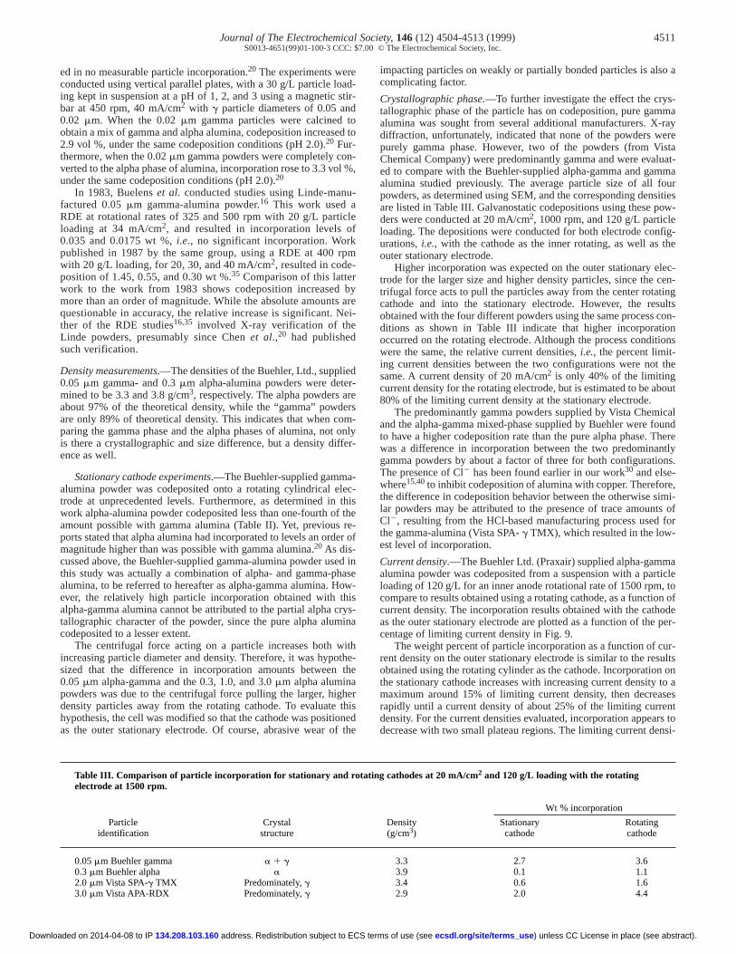
Current density.—The Buehler Ltd. (Praxair) supplied alpha-gamalumina powder was codeposited from a suspension with a paloading of 120 g/L for an inner anode rotational rate of 1500 rpmcompare to results obtained using a rotating cathode, as a functiocurrent density. The incorporation results obtained with the cathas the outer stationary electrode are plotted as a function of thecentage of limiting current density in Fig. 9.
The weight percent of particle incorporation as a function of crent density on the outer stationary electrode is similar to the reobtained using the rotating cylinder as the cathode. Incorporatiothe stationary cathode increases with increasing current densitymaximum around 15% of limiting current density, then decrearapidly until a current density of about 25% of the limiting curredensity. For the current densities evaluated, incorporation appeadecrease with two small plateau regions. The limiting current de
Table III. Comparison of particle incorporation for stationary and rotating cathodes at 20 mA/cm2 and 120 g/L loading with the rotatingelectrode at 1500 rpm.
Wt % incorporation
Particle Crystal Density Stationary Rotatingidentification structure (g/cm3) cathode cathode
0.05 mm Buehler gamma a 1 g 3.3 2.7 3.60.3 mm Buehler alpha a 3.9 0.1 1.12.0 mm Vista SPA-gTMX Predominately,g 3.4 0.6 1.63.0 mm Vista APA-RDX Predominately,g 2.9 2.0 4.4
) unless CC License in place (see abstract). ecsdl.org/site/terms_useerms of use (see
4512 Journal of The Electrochemical Society,146 (12) 4504-4513 (1999)S0013-4651(99)01-100-3 CCC: $7.00 © The Electrochemical Society, Inc.
f thery as
HCl-ode-po-posi-
luat-w-gs,. Asut atnif-
he
ention, fol-cor-ass-
therrentase,
rentletesit-
de-ontoeas-ntilpsithings aithting
ticleus-sity,po-alut-rent
e atm.
Down
ty on the stationary cathode with 120 g/L particle loading in suspesion at an anode rotational rate of 1500 rpm was experimentadetermined using polarization scans to be 34.4 mA/cm2. Whereasthe limiting current density on the inner rotating electrode for thsame combination of experimental parameters was 67 mA/cm2. Al-though the limiting current densities differ by almost a factor of twthe data for the two anode-cathode configurations can be compawhen incorporation is plotted vs. the percent limiting current densi-ty, in Fig. 9.
At the peak of the curve in Fig. 9, higher incorporation was otained on the stationary cathode, indicating that the centrifugal foenhances the codeposition at the point where codeposition is a mimum. This supports the idea that the maximum codeposition of amina in copper coincides with the point of zero charge of the caode. The centrifugal force increases the concentration of the pacles at the stationary electrode surface and holds them in place wthe metal fills in around the particles.
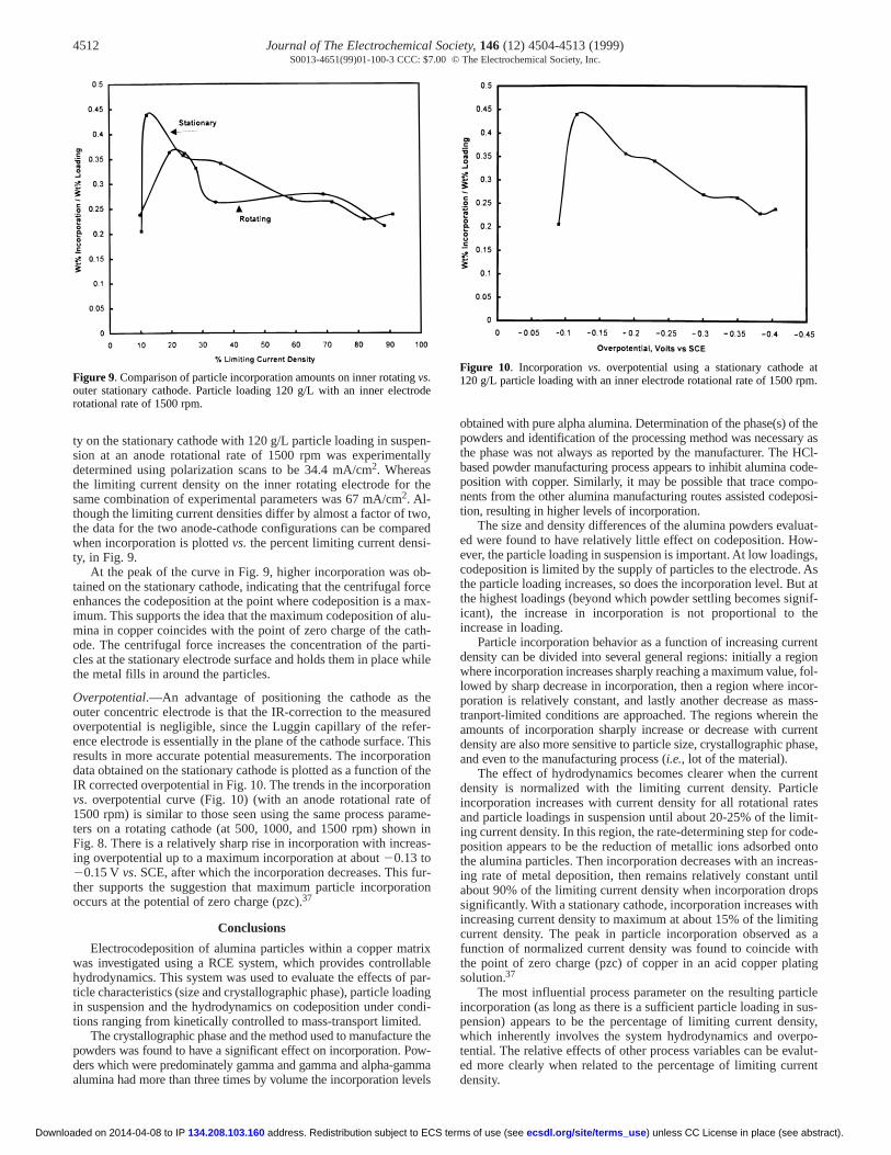
Overpotential.—An advantage of positioning the cathode as thouter concentric electrode is that the IR-correction to the measuoverpotential is negligible, since the Luggin capillary of the refeence electrode is essentially in the plane of the cathode surface. results in more accurate potential measurements. The incorporadata obtained on the stationary cathode is plotted as a function ofIR corrected overpotential in Fig. 10. The trends in the incorporativs. overpotential curve (Fig. 10) (with an anode rotational rate1500 rpm) is similar to those seen using the same process paraters on a rotating cathode (at 500, 1000, and 1500 rpm) shownFig. 8. There is a relatively sharp rise in incorporation with increaing overpotential up to a maximum incorporation at about 20.13 to20.15 Vvs. SCE,after which the incorporation decreases. This futher supports the suggestion that maximum particle incorporatoccurs at the potential of zero charge (pzc).37
Conclusions
Electrocodeposition of alumina particles within a copper matrwas investigated using a RCE system, which provides controllahydrodynamics. This system was used to evaluate the effects of ticle characteristics (size and crystallographic phase), particle loadin suspension and the hydrodynamics on codeposition under cotions ranging from kinetically controlled to mass-transport limited.
The crystallographic phase and the method used to manufacturepowders was found to have a significant effect on incorporation. Poders which were predominately gamma and gamma and alpha-gamalumina had more than three times by volume the incorporation lev
Figure 9. Comparison of particle incorporation amounts on inner rotating outer stationary cathode. Particle loading 120 g/L with an inner electrorotational rate of 1500 rpm.
address. Redistribution subject to ECS t134.208.103.160loaded on 2014-04-08 to IP
n-lly
e
o,red
b-rceax-lu-th-rti-hile
eredr-Thistion theon ofme- ins-
r-ion
ixblepar-ingndi-
thew-ma
els
obtained with pure alpha alumina. Determination of the phase(s) opowders and identification of the processing method was necessathe phase was not always as reported by the manufacturer. Thebased powder manufacturing process appears to inhibit alumina cposition with copper. Similarly, it may be possible that trace comnents from the other alumina manufacturing routes assisted codetion, resulting in higher levels of incorporation.
The size and density differences of the alumina powders evaed were found to have relatively little effect on codeposition. Hoever,the particle loading in suspension is important. At low loadincodeposition is limited by the supply of particles to the electrodethe particle loading increases, so does the incorporation level. Bthe highest loadings (beyond which powder settling becomes sigicant), the increase in incorporation is not proportional to tincrease in loading.
Particle incorporation behavior as a function of increasing currdensity can be divided into several general regions: initially a regwhere incorporation increases sharply reaching a maximum valuelowed by sharp decrease in incorporation, then a region where inporation is relatively constant, and lastly another decrease as mtranport-limited conditions are approached. The regions whereinamounts of incorporation sharply increase or decrease with cudensity are also more sensitive to particle size, crystallographic phand even to the manufacturing process (i.e., lot of the material).
The effect of hydrodynamics becomes clearer when the curdensity is normalized with the limiting current density. Particincorporation increases with current density for all rotational raand particle loadings in suspension until about 20-25% of the liming current density. In this region, the rate-determining step for coposition appears to be the reduction of metallic ions adsorbed the alumina particles. Then incorporation decreases with an incring rate of metal deposition, then remains relatively constant uabout 90% of the limiting current density when incorporation drosignificantly. With a stationary cathode, incorporation increases wincreasing current density to maximum at about 15% of the limitcurrent density. The peak in particle incorporation observed afunction of normalized current density was found to coincide wthe point of zero charge (pzc) of copper in an acid copper plasolution.37
The most influential process parameter on the resulting parincorporation (as long as there is a sufficient particle loading in spension) appears to be the percentage of limiting current denwhich inherently involves the system hydrodynamics and overtential. The relative effects of other process variables can be eved more clearly when related to the percentage of limiting curdensity.
vs.de
Figure 10. Incorporation vs. overpotential using a stationary cathod120g/L particle loading with an inner electrode rotational rate of 1500 rp
) unless CC License in place (see abstract). ecsdl.org/site/terms_useerms of use (see
Journal of The Electrochemical Society,146 (12) 4504-4513 (1999) 4513S0013-4651(99)01-100-3 CCC: $7.00 © The Electrochemical Society, Inc.
t
c
g
Do
Acknowledgments
This research was supported in part by the American Elecplaters and Surface Finishers Society (AESF), Graduate WomenScience-Sigma Delta Epsilon, and a Patricia Harris Fellowship. Tauthors would like to thank Professor J. Fransaer (now at CathoUniversity, Leuven, Belgium) for calculating the primary currendistributions.
The University of California, San Diego, assisted in meeting the publition costs of this article.
References1. R.V. Williams,Electroplat. Met. Finish.,3, 92 (1966).2. E. C. Kedward,Cobalt,3, 53 (1973).3. V. P. Greco,Plat. Surf. Finish.,76, 68 (1989). 4. A. Hovestad and L. J. J. Janssen,J. Appl. Electrochem.,40, 519 (1995).5. P. R. Ebdon,Plat. Surf Finish.,75, 65 (1988).6. Y. Sofer, Y. Yarnitzky, and S. F. Dimfeld,Surf. Coat. Technol.,42, 227 (1990).7. I. Ahmad, V. P. Greco, and J. M. Barranco,Composite J.,2, 18 (1967).8. R. Mevrel,Mater. Sci. Eng.,A120, 13 (1989).9. G. A. Malone,Plat. Surf. Finish.,78, 58 (1991).
10. S. Pushpavanam, M. Pushpavanam, S. R. Natarajan, K. C. Narasimham, aChinnasamy,Int. J. Hydrogen Energy,18, 277 (1993).
11. M. Viswanathan,Met. Finish.,71, 38 (1973).12. J. R. Roos, J. P. Celis, and J. A. Hensen,Trans. Inst. Met. Finish.,55, 113 (1977).13. D. W. Snaith and P. D. Groves,Trans. Inst. Met. Finish.,56, 9 (1978).14. J. P. Celis, H. Kelchtermans, and J. R. Roos,Trans. Inst. Met. Finish.,56, 41
(1978).15. C. White and J. Foster,Trans. Inst. Met. Finish.,59, 9 (1981).16. C. Buelens, J. P. Celis, and J. R. Roos,J. Appl. Electrochem.,13, 541 (1983).17. S. W. Watson and R. P. Walters,J. Electrochem. Soc.,138, 3633 (1991).
address. Redistribution subject to ECS 134.208.103.160wnloaded on 2014-04-08 to IP
ro- inhelict
a-
nd S.
18. H. Hayashi, S. Izumi, and I. Tari,J. Electrochem. Soc.,140, 362 (1993).19. P. R. Webb and N. L. Robertson,J. Electrochem. Soc.,121, 669 (1994).20. E. S. Chen, G. R. Lakshminarayanan, and F. K. Sautter,Metall. Trans.,2, 937
(1971).21. N. Guglielmi and G. Icardi,Metall. Ital., (11), 420 (1970).22. G. N. K. R. Bapu,Surf. Coat. Tech.,67, 105 (1994).23. M. Yoshida and T. Izaki, in Proceedings of AESF Continuous Steel Strip Platin
Symposium, pp.111-122, May 4-6, 1993.24. M. Kimoto, A. Yakawa, T. Tsuda, and R. Kammel,Metallwiss. Tech.,44, 1148
(1990).25. C. Vest and D. F. Bazzarre,Metal Finish., (11), 52 (1967).26. J. Zahavi and J. Hazen,Plating Surf. Finish., (2) 57 (1983).27. J. L. Valdes, Ph.D. Thesis, Columbia University, New York, New York (1987).28. C. Buelens, Ph.D. Thesis, Catholic University, Leuven, Belgium (1984).29. J. P. Celis, J. A. Helsen, P. Hermans, and J. R. Roos,Anal. Chim. Acta,92, 413
(1977).30. J. L. Stojak, Ph.D. Thesis, University of California, San Diego (1997).31. M. A. Brimi and J. R. Luck,Electrofinishing, American Elsevier Publishing Com-
pany, Inc., New York (1965).32. M. Eisenberg, C. W. Tobias, and C. R. Wilke,J. Electrochem. Soc.,101, 306
(1954).33. J. S. Newman,Electrochemical Systems, 2nd ed., p. 379, 116, Prentice Hall, Engle-
wood Cliffs, NJ (1973).34. CRC Handbook of Chemistrv and Physics, R. C. Weast, Editor, CRC Press, Inc.,
Boca Raton, FL (1979).35. J. P. Celis, J. R. Roos, and C. Buelens,J. Electrochem. Soc.,134, 1402 (1987).36. D. R. Gabe and D. J. Robinson,Trans. Inst. Met. Finish.,49, 17 (1971).37. J. Fransaer, Ph.D. Thesis, Catholic University, Leuven, Belgium (1994).38. M. L. Foresti, G. Pezzatini, and M. Innocenti,J. Electroanal. Chem.,434, 191
(1997).39. F. Dorre and H. Hubner,Alumina: Processing, Properties and Applications,
Springer-Verlag, New York (1984).40. G. Hutting,Angew. Chem.,53, 35 (1940).41. C. C. Lee and C. C. Wan,J. Electrochem. Soc.,135, 1930 (1988).
) unless CC License in place (see abstract). ecsdl.org/site/terms_useterms of use (see