Embed Size (px)
Citation preview
HAL Id: hal-00987387https://hal.archives-ouvertes.fr/hal-00987387
Submitted on 13 May 2014
HAL is a multi-disciplinary open accessarchive for the deposit and dissemination of sci-entific research documents, whether they are pub-lished or not. The documents may come fromteaching and research institutions in France orabroad, or from public or private research centers.
L’archive ouverte pluridisciplinaire HAL, estdestinée au dépôt et à la diffusion de documentsscientifiques de niveau recherche, publiés ou non,émanant des établissements d’enseignement et derecherche français ou étrangers, des laboratoirespublics ou privés.
Investigation of delamination mechanisms during a laserdrilling on a cobalt-base superalloy
Jérémy Girardot, Matthieu Schneider, Laurent Berthe, Véronique Favier
To cite this version:Jérémy Girardot, Matthieu Schneider, Laurent Berthe, Véronique Favier. Investigation of delamina-tion mechanisms during a laser drilling on a cobalt-base superalloy. Journal of Materials ProcessingTechnology, Elsevier, 2013, 213, pp.1682-1691. �10.1016/j.jmatprotec.2013.04.003�. �hal-00987387�

Science Arts & Métiers (SAM)is an open access repository that collects the work of Arts et Métiers ParisTech
researchers and makes it freely available over the web where possible.
This is an author-deposited version published in: http://sam.ensam.euHandle ID: .http://hdl.handle.net/10985/8106
To cite this version :
Jérémy GIRARDOT, Matthieu SCHNEIDER, Laurent BERTHE, Véronique FAVIER - Investigationof delamination mechanisms during a laser drilling on a cobalt-base superalloy - Journal ofMaterials Processing Technology - Vol. 213, p.1682-1691 - 2013
Any correspondence concerning this service should be sent to the repositoryAdministrator : [email protected]

Investigation of delamination mechanisms during a laser drilling on a
cobalt-base superalloy�
J. Girardot ∗, M. Schneider, L. Berthe, V. Favier
Arts et Metiers ParisTech, PIMM UMR CNRS 8006, 151 Bd de l’Hôpital, 75013 Paris, France
Keywords:
Cobalt-base superalloy
Laser drilling
Fast camera analysis
Thermal barrier coating
Haynes 188
a b s t r a c t
Temperatures in the high pressure chamber of aircraft engines are continuously increasing to improve
the engine efficiency. As a result, constitutive materials such as cobalt and nickel-base superalloys need
to be thermally protected. The first protection is a ceramic thermal barrier coating (TBC) cast on all the
hot gas-exposed structure. The second protection is provided by a cool air layer realized by the use of
a thousand of drills on the parts where a cool air is flowing through. The laser drilling process is used
to realize these holes at acute angles. It has been shown on coated single crystal nickel-base superalloy
that the laser drilling process causes an interfacial cracking (also called delamination), detected by a
cross section observation. The present work aims at characterizing interfacial cracking induced by laser
drilling on coated cobalt-base super alloy. On the one hand, this work attempted to quantify the crack by
several microscopic observations with regards to the most significant process parameters related as the
angle beam. On the other hand, we studied the difference of the laser/ceramic and the laser/substrate
interaction with real time observation by using a fast movie camera.
1. Introduction
In order to reduce gases emission and improve engine efficiency,
temperatures in the high pressure chamber of aircraft engines are
continuously increasing (currently up to 2300 K). As a result, con-
stitutive materials such as cobalt and nickel-base superalloys need
to be thermally protected. The first protection consists in covering
the hot gas-exposed structure with a ceramic thermal barrier coat-
ing (TBC) and a bond coating (BC) (Fig. 1). The second protection
is provided by a cool air layer produced by the use of thousands of
drills made on the components through which a cool air is flowing.
This protection method is illustrated in Fig. 2 where the typical
geometry of a turbine blade in an aircraft high pressure chamber is
shown.
Laser drilling is a non-contact machining process which is very
useful to make acute angled holes. Two different drilling modes,
labeled as percussion drilling and trepan drilling are typically used
in the industry. The percussion mode is a fixed beam drilling
� This is an open-access article distributed under the terms of the Creative Com-
mons Attribution-NonCommercial-No Derivative Works License, which permits
non-commercial use, distribution, and reproduction in any medium, provided the
original author and source are credited.∗ Corresponding author. Tel.: +33 1 71 93 65 62.
E-mail addresses: [email protected] (J. Girardot),
[email protected] (M. Schneider), [email protected]
(L. Berthe), [email protected] (V. Favier).
whereas the trepan mode involves cutting with a circular trajec-
tory centered with the hole. The range of power density generally
used for both trajectories is about 1–50 MW/cm2 during a pulse
of about 1 ms. In percussion drilling mode, multiples pulses are
produced until the breakthrough of the sheet. The advantage of
this last method with regard to the trepan mode is a reduction in
processing time by a factor of four (Sezer et al., 2006). In this range
of power density, the physics process consists in heating the sur-
face by focusing the laser beam with temperatures up to the vapor
point. The melt part is then ejected by the vapor pressure and the
hole is created (Semak, 1997). In this study, only the percussion
mode was used to drill.
Laser drilling induces different types of defects such as a recast
layer and spatters on the surface (Sezer et al., 2006) which are
already observed in literature by means of cross section observa-
tion. Especially, the effect of the process parameters on the different
heat affected layer across the hole was studied. Voisey et al. (2004)
studied the effect of assist gas pressure on the geometry and the
residual metallurgical state after a percussion laser drilling. It has
been reported that the pressure and the nature of the gas have no
mechanical or chemical effect on the component. On the contrary,
the angle beam, its power density and the repetition rate are three
parameters which modify the geometry of the hole and the size of
the recast layer.
But as report in Sezer et al. (2006) and Sezer and Li (2009), the
major default is the delamination of TBC. Delamination is cracking
which leads to failure of the coating, damaging the turbine engine.

Fig. 1. Micrography of the multilayer material used in critical aircraft parts.
The frequency of multipulses is the major factor for the localization
of the delamination (Sezer and Li, 2009). At low frequency (around
1 Hz), the crack initiates at the BC/substrate interface due to several
thermal shock cycling and the associated thermally grown oxide. At
high frequency (around 10 Hz), it is located at the BC/TBC interface
which is a major threat to the integrity of the engine. The integrity of
the component is assessed by the delamination length: the larger,
the more harmful. The delamination length increases with the angle
beam and is commonly measured in the cross section of the hole
(Sezer et al., 2006; Voisey et al., 2001; Kamalu et al., 2002) using
optical micrographs.
Results in literature refer to a nickel-base superalloy substrate.
The material drilled in this study is the cobalt-base superalloy
(Haynes 188 (HS188 or ams5608)) which offers high strength and
oxidation resistance to 1100 ◦C (Van Deventer, 1977) and is used in
turbine engine typically working at 2000 ◦C. The substrate is cov-
ered with a ceramic coating. The present work aims at describing
and quantifying delamination induced by percussion laser drilling
at various angles on this multilayer material. Laser repetition rate
is 10 Hz. Thus, the observed crack is expected to be located at the
Fig. 2. Representation of the cooling method of turbine blade using thousands of
holes in which a cool air is flowing in a turbine blade.
Table 1
Plasma spraying parameters.
Ceramic layer powder YSZ
Binding layer powder NiCrAlY
Ceramic layer plasma gas flow 30 l/min (Ar)
Binding layer plasma gas flow 4 l/min (H2)
Spray distance 80 mm
Number of passes from 5 to 10
BC/TBC interface. The first section goes over longitudinal section
observations of the holes pulse after pulse with a new approach to
observe the evolution of the crack. The second section shows a new
investigation to observe the morphology of the crack surface always
with a micrography observation. Furthermore, visualization in real
time of the laser drilling with a fast camera allowed us to discuss
phenomena in relation with material observations.
2. Experimental set up
2.1. Materials
The laser-drilled material was a multilayer material. The metal
substrate was a cobalt-base superalloy used in the manufacture of
aircraft components. Its denomination is “Haynes 188” or “HS188”
or “ams5608”. A nickel/chromium (NiCrAlY) bond coating was
first sprayed on the workpiece surface to enhance the adhesion
of the thermal barrier coating. The thickness of the BC is around
0.2 mm. The TBC consisted of a Zirconium–Yttrium oxide ceramic
and is 0.5 mm thick. The manufacturing process is the conven-
tional plasma spraying (Fauchais, 2004) and parameters are listed
in Table 1. Laser drilling was carried out on sheets of 2 mm.
2.2. Process and fast camera parameters
The laser source is a TRUMPF HL201p (Nd:YAG) operating at
1.064 �m. It delivers a reliable circular and uniform spatial intensity
distribution of light. The beam spot diameter can be fixed whatever
the peak power of the laser source. It was here equal to 300 �m. The
absorbed intensity which is the effective energy can be deduced
from the peak power measurement (Schneider et al., 2007a, 2008).
In this study, the incident intensity, so called Iinc, was held constant
and equal to 18.4 MW/cm2 which coresponds to a peak power of
13 kW. The focal distance was held constant for all the drillings. The
work piece was drilled from TBC side. One to eight pulses with a
frequency of 10 Hz were delivered. The pulse duration is 1 ms. The
shot angles, so called ˇ, were selected equal to 20◦, 30◦ and 40◦
because they induced delamination on nickel-base superalloy AM1
with coating (Kamalu et al., 2002). Shots at 90◦ were also performed
as shot references. Oxygen assist gas was used coaxially with the
laser beam via a 1.5 mm exit diameter converging nozzle. The gas
pressure was held constant at 6 bar.
The laser process parameters are listed in Table 2:
A Photron RS 250k camera with a band pass filter was used
to investigate the fluid ejection dynamics following the work of
Schneider et al. (2007a). The experimental set up is described in
Table 2
Laser process parameters.
Laser source TRUMPF HL201p (Nd:YAG)
Laser incident intensity Iinc = 18.4 MW/cm2
Beam diameter 300 �m
Pulse duration 1 ms
Assist gas O2
Shot angle ˇ = 40◦ , 30◦ and 20◦
Number of pulse from 1 to 8 pulses
Repetition rate 10 Hz
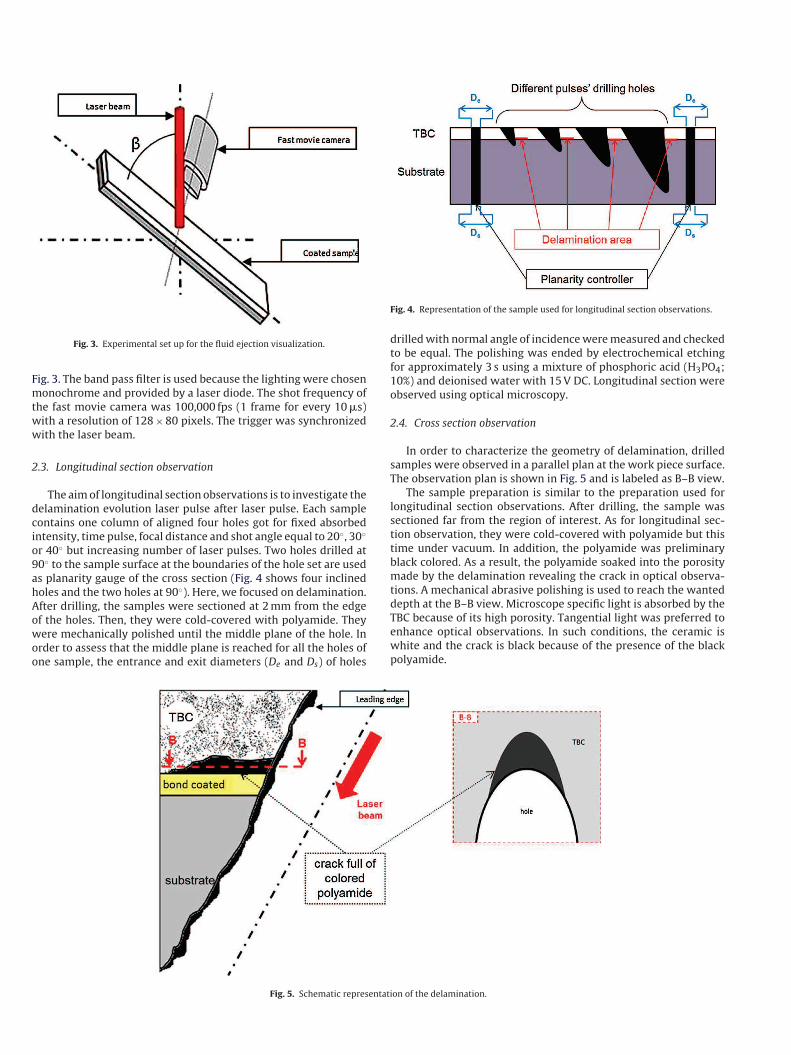
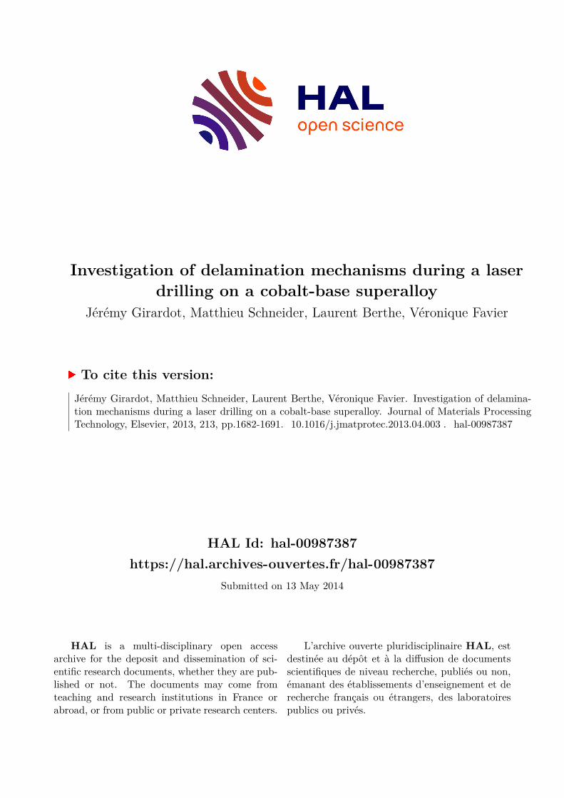
Fig. 3. Experimental set up for the fluid ejection visualization.
Fig. 3. The band pass filter is used because the lighting were chosen
monochrome and provided by a laser diode. The shot frequency of
the fast movie camera was 100,000 fps (1 frame for every 10 �s)
with a resolution of 128 × 80 pixels. The trigger was synchronized
with the laser beam.
2.3. Longitudinal section observation
The aim of longitudinal section observations is to investigate the
delamination evolution laser pulse after laser pulse. Each sample
contains one column of aligned four holes got for fixed absorbed
intensity, time pulse, focal distance and shot angle equal to 20◦, 30◦
or 40◦ but increasing number of laser pulses. Two holes drilled at
90◦ to the sample surface at the boundaries of the hole set are used
as planarity gauge of the cross section (Fig. 4 shows four inclined
holes and the two holes at 90◦). Here, we focused on delamination.
After drilling, the samples were sectioned at 2 mm from the edge
of the holes. Then, they were cold-covered with polyamide. They
were mechanically polished until the middle plane of the hole. In
order to assess that the middle plane is reached for all the holes of
one sample, the entrance and exit diameters (De and Ds) of holes
Fig. 4. Representation of the sample used for longitudinal section observations.
drilled with normal angle of incidence were measured and checked
to be equal. The polishing was ended by electrochemical etching
for approximately 3 s using a mixture of phosphoric acid (H3PO4;
10%) and deionised water with 15 V DC. Longitudinal section were
observed using optical microscopy.
2.4. Cross section observation
In order to characterize the geometry of delamination, drilled
samples were observed in a parallel plan at the work piece surface.
The observation plan is shown in Fig. 5 and is labeled as B–B view.
The sample preparation is similar to the preparation used for
longitudinal section observations. After drilling, the sample was
sectioned far from the region of interest. As for longitudinal sec-
tion observation, they were cold-covered with polyamide but this
time under vacuum. In addition, the polyamide was preliminary
black colored. As a result, the polyamide soaked into the porosity
made by the delamination revealing the crack in optical observa-
tions. A mechanical abrasive polishing is used to reach the wanted
depth at the B–B view. Microscope specific light is absorbed by the
TBC because of its high porosity. Tangential light was preferred to
enhance optical observations. In such conditions, the ceramic is
white and the crack is black because of the presence of the black
polyamide.
Fig. 5. Schematic representation of the delamination.
Fig. 6. Hole micrograph. (Iinc = 18.4 MW/cm2; ˇ = 40◦; 1 pulse).
3. Results
3.1. Longitudinal section observation
Figs. 6–9 show longitudinal section micrographies of holes
angles at 40◦ to the workpiece surface after one, two, three and
four pulses:
- The first laser pulse (Fig. 6) produced a hole which only broke
through the two coated layers. The hole penetrated less than
100 �m into the metallic substrate and no crack occurred.
- At the second laser pulse (Fig. 7), the hole penetrated at 1 mm
into the substrate and several defects are observed. Firstly, the
hole diameter in the ceramic coating is smaller than in the BC and
metallic substrate. In other word, the hole profile changed as the
interface is crossed. Moreover, a thick recast layer of a mixture of
ceramic and metal is observed around the BC/substrate interface
at both leading and trailing edges though it is thicker at the trail-
ing side. A delamination crack is observed at the leading edge, in
the TBC but very closed to the TBC/BC interface as expected from
literature (Sezer and Li, 2009) and its length is 0.23 mm. As report
in (Sezer et al., 2006), Fig. 7 shows also the different character-
istics layers in laser drilling of metal, and especially the recast
layer.
- At the third laser pulse (Fig. 8), the hole penetrated at almost 2 mm
into the metallic substrate. The hole diameter slightly decreases
with depth and is uneven. This is due to the presence of localized
resolidified layer at the trailing edge. The delamination length
increases and its value is 0.85 mm.
- The fourth laser pulse (Fig. 9) corresponds to the breakthrough of
the coated sheet for a 40◦ shot angle. The melt is no more ejected
upwards through the hole entrance but is flushed downward the
hole exit. The delamination crack length does not increase any-
more regarding to measurement errors.
Similar observations were found for laser drilling at 30◦ and
20◦. Fig. 10 reports the delamination crack length with respect to
the number of pulse for the three different drilling angles 40◦, 30◦,
and 20◦. Each value is the average of two measurements done on
isoparameter samples. Despite these few numbers of samples, the
tendency is in a good agreement with the literature results (Voisey
et al., 2001; Kamalu et al., 2002). Standard deviation is represented
Fig. 7. Hole micrograph (a) and delamination zoom (b). (Iinc = 18.4 MW/cm2; ˇ = 40◦; 2 pulses).
Fig. 8. Hole micrograph (a) and delamination zoom (b). (Iinc = 18.4 MW/cm2; ˇ = 40◦; 3 pulses).

Fig. 9. Hole micrograph (a) and delamination zoom (b). (Iinc = 18.4 MW/cm2; ˇ = 40◦; 4 pulses).
Fig. 10. Evolution of delamination length for three drilling angles (ˇ = 40◦ , 30◦ and 20◦).
by error bars. The delamination crack length increases with
decreasing drilling angle to surface as found for coated nickel-base
superalloys (Voisey et al., 2001; Kamalu et al., 2002). Indeed, for
a 3 pulse hole, delamination length is equal to 0.7 mm with a
40◦ shot angle, 1 mm with 30◦ and 1.6 mm with 20◦. At 90◦, no
delamination occurs as shown in Fig. 11. However, the shouldered
shape of the hole at the TBC/substrate interface mentioned above is
also observed. Measured lengths are consistent with results found
in literature for a coated nickel-base superalloy substrate (Sezer
and Li, 2009). Fig. 12 shows the crack area for a delamination crack
length of 2.2 mm induced by eight laser pulses with 20◦ shot angle.
The crack path is not planar because it probably follows the BC/TBC
interface roughness. However, the non-smooth and non-planar
crack path makes difficult precise measurement of the crack
front in the cross section micrograph. According to the author’s
knowledge, this issue was never mentioned in literature despite
this method is systematically used (Sezer and Li, 2009; Kamalu
et al., 2002). It explains why the error in delamination crack length
measurements increases with the crack length in Fig. 10.
4. Cross section observation
Fig. 13 displays coated sheet longitudinal section observations
(along the B–B view) at three depths in ceramic. The laser angle to
the surface is 20◦ and the pulse number is six.
Fig. 13(a) and (b) corresponds to the so-called depth 1 and 2 and
are above the delamination crack. The elliptic trace of the black hole
Fig. 11. Hole micrography. (Iinc = 18.4 MW/cm2; ˇ = 90◦; 4 pulses).

Fig. 12. Delamination zoom of the front crack area. (Iinc = 18.4 MW/cm2; ˇ = 20◦; 8
pulses).
is marked using dashed line. The ceramic appears whitish and dis-
plays a very heterogeneous microstructure revealed by tangential
light of the optical microscope. After the last polishing operation,
the depth where the delamination crack is located was reached
(Fig. 13(c)). The delamination crack corresponds to the dark zone
(indicated by the red dashed line) got with soaked black polyamide
(see Section 2.4). The 2D crack front is very winding but propagates
mainly along the leading direction of the inclined hole. No crack
was observed at other places. The delamination crack propagation
is probably controlled by the ceramic porosity, the BC/TBC interface
and the mechanical loading which takes place during the process.
This point is discussed in the last section of the paper. The length of
the crack in the 2D view is in good agreement with measurements
obtained using cross section observations.
4.1. Fast camera movies
In order to understand why delamination occurs only at the sec-
ond pulse, laser drilling operation in inclined angles of incidence
were observed in real time with a fast camera. Results obtained
for coated cobalt-base superalloy were compared to the literature
results (Schneider et al., 2007b) obtained on the same metallic sub-
strate but without coating to investigate the effect of the TBC in the
laser process.
Fig. 14 shows fast camera images of the melt and gas ejection
taken at the same time during the first pulse fired at 90◦ to the sur-
face for both systems (Co-base superalloy with and without TBC).
According to Schneider et al. (2011), the hydrodynamic behavior
of the gas ejected is straight related to the surface temperature of
the vapor front during the process. Thus, surface temperatures can
be estimated and is more than 5000 K for an incident intensity of
25.4 MW/cm2 which corresponds to a 18 kW peak power for the
laser source. The local pressure at the same range of intensity is
about 100 bar. On the movies, a shock wave was observed during
the drilling for both systems. This shows that gas behaviors were
both supersonic but the size of the shock wave was almost two
Fig. 13. Hole micrograph in the longitudinal section at three different depths (a), (b) and (c). (Iinc = 18.4 MW/cm2; ˇ = 20◦; 6 pulses).

Fig. 14. Hydrodynamics of the gas ejection on the uncoated substrate (a) and the coated substrate (b) during laser drilling at normal angle of incidence. (Iinc = 25.4 MW/cm2;
ˇ = 90◦).
times larger in the case of coated substrate drilling than in the case
of uncoated substrate drilling. This indicates that the temperature
and ejection speed are much higher for a ceramic/laser than for a
metal/laser interaction. Besides, for the drilling on uncoated sub-
strate, liquid ejection as drops was observed on the edges of the
ejection area for free-TBC substrate.
Since the first three pulses are responsible for the main part
of the delamination crack length, the hydrodynamics of the vapor
and melt were registered for drilling at 20◦ to the surface for the
coated substrate. The incident intensity was also selected equal to
25.4 MW/cm2. Fig. 15 shows the fluids ejection for the three pulses
at 300 �s after the beginning of the pulse.
The fluid ejection for the first pulse is far different from the
two others. This change corresponds to the instant at which the
hole penetrates into the substrate and reveals the change between
ceramic/laser and laser/metal interaction. During the first pulse
associated with ceramic/laser interaction, the fluid ejected seems
to be mainly gaseous whereas it is mainly liquid for the second and
the third pulses associated with metal/laser interaction.
5. Discussion
Laser drilling at acute angles of coated superalloys in industry
involves complex phenomena mainly related to the fact that the
ceramic TBC and the metallic substrate have very different thermal
and mechanical properties and also that the drilling at acute angles
is a non-symmetrical process inducing different types of damage
around the hole.
Fast camera analysis showed that the presence of TBC induces
a much higher surface temperature when the hole penetrates
into the substrate than in the substrate depth whatever the laser
beam of incidence. The first consequence is a taper shape of the
Fig. 15. Hydrodynamics of the gas and melt ejection on the coated substrate for the
first pulse (a), for the second pulse (b) and for the third pulse (c). (Iinc = 25.4 MW/cm2;
ˇ = 20◦).
hole through the sheet thickness since the temperature surface
decreases with increasing depth. The second consequence is a
shouldered shape of the hole at the TBC/substrate interface. The
thickness of the molten zone and removed material is higher in
the substrate than in the ceramic due to the larger conductivity
and the lower melting point of the superalloy. This result was
previously suggested by Voisey and Clyne (2004) who predicted
the thermal fields for a TBC/nickel-base superalloys (so similar
to the TBC/cobalt-base superalloys studied here as far as thermal
properties are concerned) using finite difference modeling. They
showed the presence of a discontinuity in the thermal field at the
TBC/substrate interface. The thickness of the molten zone is higher
in the substrate than in the ceramic due to the larger conductivity
and the lower melting point of the superalloy. The edge area of the
smaller diameter hole in the ceramic act as stopper for the liquid
ejection and can play a role in the delamination crack propagation
as discussed later.
Investigations using cross optical micrographs revealed that at
90◦ laser beam incidence, no delamination crack was observed
despite the presence of the shouldered shape of the hole.
Crack delamination appears at inclined drilling in the TBC at the
BC/TBC interface at the leading edge but only from the second laser
pulse when the laser beam interacts with the metallic substrate.
The crack is winding and not planar and propagates during
the drilling process. Its propagation takes place along the BC/TBC
interface and is directional from the hole leading edge. The over-
all propagation direction is contained in the middle cross plan of
the hole. This shows that the delamination crack propagation path
is mainly controlled by the TBC microstructure and mechanical
stresses applying at the BC/TBC substrate. The crack propagation
stops when the laser beam passes through the sheet sample.
Kamalu et al. (2002) assumed that initiation of delamination
in thermal barrier coated nickel-base superalloy was related with
steep thermal gradients produced when laser drilling. Thermally
induced fracture between two pores in the TBC would be responsi-
ble for the delamination initiation. This mechanism should involve
whatever the beam angle of incidence. However and on the con-
trary to Kamalu et al. (2002) results, no delamination was observed
when 90◦ laser drilling. It is worth noticing that TBC/BC delami-
nation was found below 0.2 mm for the normal incidence drilling,
while it was consistently above 0.2 mm for the inclined holes in
Kamalu et al. works. This maybe explains why the delamination was
not observed at 90◦ drilling in this work. Sezer and Li (2009) sug-
gested the key role of mechanical stresses induced by the upward
melt ejection in the initiation and propagation of delamination
without clearly distinguished the two stages.
As no significant delamination crack was observed at 90◦ laser
drilling, we assumed that it was only due to mechanical stresses.
Thermal effects are thus neglected. Fig. 16 illustrates two possible
mechanical effects applying on the BC/TCB interface.

Fig. 16. Representation of the delamination model in inclined configuration.
Fig. 17. Relative force Fy as a function of the beam angle of incidence for different TBC thickness.
As mentioned above, the ceramic at the hole shape discontinu-
ity partially stops the melt ejection. As a result, the molten material
applies a vertical force so called FL (or equivalently the liquid pres-
sure PL) on the TBC as illustrated in Fig. 16. This effect takes place
whatever the laser beam angle of incidence. Let us consider the
hole diameters called Dc in the ceramic and Ds in the substrate. The
angle beam is called ˇ and e the TBC thickness.
The surface areas on which the liquid pressure PL applied is SL.
According to Fig. 16, the surface SL is calculated as a difference of
two centered elliptic surfaces, due to the projection of two inclined
cylinder following the vertical direction:
SL =
(
�Ds
2 sin (ˇ)
Ds
2
)
−
(
�Dc
2 sin (ˇ)
Dc
2
)
=�
4 sin (ˇ)(D2
s − D2c ) (1)
The liquid pressure can be calculated using the Bernoulli equa-
tion:
PL =1
2�v
2L (2)
� is the liquid density and is equal here to 6980 kg/m3. The liquid
velocity vL was estimated using the fast camera analysis. Indeed,
by comparing the position of a particle in the liquid flow at two
different times, an average velocity was found about 50 m/s. As a
result, PL was estimated to 87 bar.
Besides, vapor pressure applies also on the inclined leading edge
a vertical force so called FG (Fig. 16). The surface area on which the
gas pressure applies is SG. SG is calculated as the intersection of two
shifted ellipses. The detail of the calculation is shown in Appendix
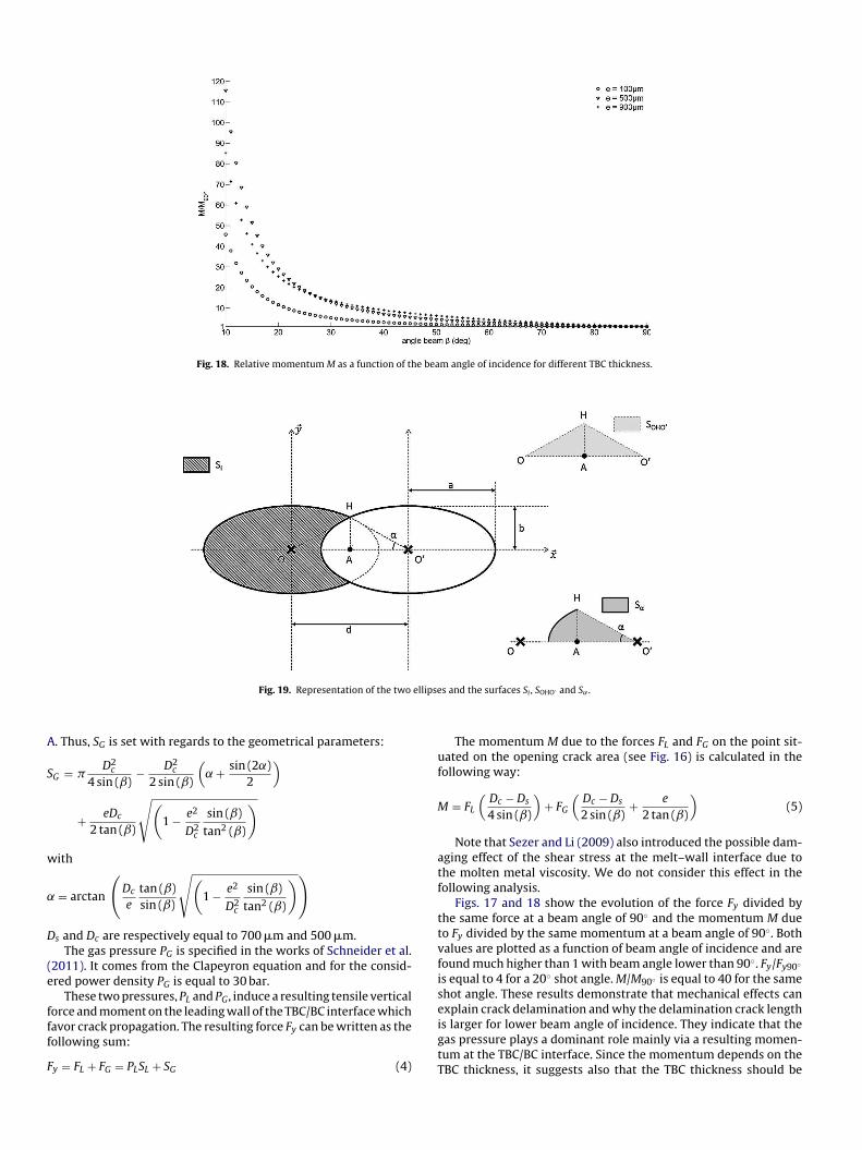
Fig. 18. Relative momentum M as a function of the beam angle of incidence for different TBC thickness.
Fig. 19. Representation of the two ellipses and the surfaces Si , SOHO′ and S˛ .
A. Thus, SG is set with regards to the geometrical parameters:
SG = �D2
c
4 sin (ˇ)−
D2c
2 sin (ˇ)
(
˛ +sin (2˛)
2
)
+eDc
2 tan (ˇ)
√
(
1 −e2
D2c
sin (ˇ)
tan2 (ˇ)
)
with
˛ = arctan
(
Dc
e
tan (ˇ)
sin (ˇ)
√
(
1 −e2
D2c
sin (ˇ)
tan2 (ˇ)
)
)
Ds and Dc are respectively equal to 700 �m and 500 �m.
The gas pressure PG is specified in the works of Schneider et al.
(2011). It comes from the Clapeyron equation and for the consid-
ered power density PG is equal to 30 bar.
These two pressures, PL and PG, induce a resulting tensile vertical
force and moment on the leading wall of the TBC/BC interface which
favor crack propagation. The resulting force Fy can be written as the
following sum:
Fy = FL + FG = PLSL + SG (4)
The momentum M due to the forces FL and FG on the point sit-
uated on the opening crack area (see Fig. 16) is calculated in the
following way:
M = FL
(
Dc − Ds
4 sin (ˇ)
)
+ FG
(
Dc − Ds
2 sin (ˇ)+
e
2 tan (ˇ)
)
(5)
Note that Sezer and Li (2009) also introduced the possible dam-
aging effect of the shear stress at the melt–wall interface due to
the molten metal viscosity. We do not consider this effect in the
following analysis.
Figs. 17 and 18 show the evolution of the force Fy divided by
the same force at a beam angle of 90◦ and the momentum M due
to Fy divided by the same momentum at a beam angle of 90◦. Both
values are plotted as a function of beam angle of incidence and are
found much higher than 1 with beam angle lower than 90◦. Fy/Fy90◦
is equal to 4 for a 20◦ shot angle. M/M90◦ is equal to 40 for the same
shot angle. These results demonstrate that mechanical effects can
explain crack delamination and why the delamination crack length
is larger for lower beam angle of incidence. They indicate that the
gas pressure plays a dominant role mainly via a resulting momen-
tum at the TBC/BC interface. Since the momentum depends on the
TBC thickness, it suggests also that the TBC thickness should be

diminished to reduce the mechanical impact on crack delamina-
tion. Further experiments done with coated samples with different
TBC thickness are needed to assess these theoretical results.
6. Conclusion
Interrupted laser drilling of TBC cobalt-base superalloy was car-
ried out varying the beam angles of incidence. Crack delamination
appears at inclined drilling in the TBC at the BC/TBC interface at the
leading edge but only from the second laser pulse when the laser
beam interacts with the metallic substrate. The laser drilling from
the TBC side induces much higher temperature at the TBC/substrate
interface than far from it. It results in the presence of a shoulder in
the hole profile. This shoulder acts as stopper for the liquid ejection
inducing tensile mechanical stresses at the BC/TBC interface and
can favor delamination crack propagation. However, it was shown
that the pressure due to both the molten metal and vapor applying
on the inclined leading ceramic wall of the hole mainly responsible
for crack delamination. It results in a vertical force and moment on
the TBC/BC. Crack propagation is mainly controlled by mechanical
stresses. However, it was shown that the crack path is governed by
the microstructure of the ceramic and the roughness of the BC/TBC
interface.
Acknowledgments
This work has been supported by an aeronautical industrial part-
ner and the National Research Agency (ANR).
Appendix A.
The aim of this section is to calculate the surface called Si with
respect to the distance a, b and d by referring to Fig. 19.
A.1. Calculation of SOHO
′
The first step is to obtain the surface of the triangle described
by the three points {O H O′}. The length of the segment ||AH|| is
deduced of the cartesian description for an ellipse with the semi-
minor and semi-major axis a and b:
x2
a2+
y2
b2= 1 (A1)
By taking x = d/2, the length ||AH|| is:
∥
∥AH∥
∥ = b
√
(
1 −d2
4a2
)
(A2)
and the surface of the triangle {O H O′}, what we will call SOHO
′ , is:
SOHO
′ =db
2
√
(
1 −d2
4a2
)
(A3)
A.2. Calculation of S˛
The second step is to obtain the surface of the circular sector
described by the angle ˛. This surface will be called̂
(O′
HO). The
angle ˛ which corresponds to the S˛ angle is obtained by trigonom-
etry:
˛ = arctan
(
2b
d
√
(
1 −d2
4a2
)
)
(A4)
and as the circular sector surface S� for an anyone � angle in an
ellipse is:
ab
∫ �
0
1 + cos (2u)
2du (A5)
the surface S˛ is then:
S˛ = ab
(
˛
2+
sin (2˛)
4
)
(A6)
A.3. Calculation of Si
By a linear combination of these different surfaces, Si is equal to
Si = �ab − 2(2S˛ − SOHO
′ ) = �ab − 2ab
(
˛ +sin (2˛)
2
)
+ db
√
(
1 −d2
4a2
)
(A7)
References
Fauchais, P., 2004. Understanding plasma spraying. Journal of Physics D: AppliedPhysics 37, R88–R108.
Kamalu, J., Byrd, P., Pitman, A., 2002. Variable angle laser drilling of ther-mal barrier coated nimonic. Journal of Materials Processing Technology 122,
355–362.
Schneider, M., Berthe, L., Fabbro, R., Muller, M., 2008. Measurement of laser absorp-
tivity for operating parameters characteristic of laser drilling regime. Journal of
Physics D: Applied Physics 41, 15502.Schneider, M., Fabbro, R., Berthe, L., Muller, M., 2007a. Study of hole prop-
erties in percussion regime with a new analysis method. Journal of LaserMicro/Nanoengineering 2, 128–132.
Schneider, M., Fabbro, R., Berthe, L., Muller, M., 2007b. Influence of incident angleon laser drilling. In: Proceedings in ICALEO, pp. 641–646.
Schneider, M., Girardot, J., Berthe, L., 2011. Recoil pressure and surface temperaturein laser drilling. In: Proceedings in ICALEO.
Semak, V.A.M., 1997. The role of recoil pressure in energy balance dur-ing laser materials processing. Journal of Physics D: Applied Physics 30,
2541–2552.Sezer, H.K., Li, L., 2009. Mechanisms of acute angle laser drilling induced thermal
barrier coating delamination. Journal of Manufacturing Science and Engineering131, 01014.
Sezer, H.K., Li, L., Schmidt, M., Pinkerton, A.J., Anderson, B., Williams, P., 2006. Effectof beam angle on HAZ, recast and oxide layer characteristics in laser drilling of
TBC nickel superalloys. International Journal of Machine Tools and Manufacture
46, 1972–1982.Van Deventer, E.H., 1977. Hydrogen permeability of Haynes alloy 188. Journal of
Nuclear Materials 66, 325–328.
Voisey, K.T., Clyne, T.W., 2004. Laser drilling of cooling holes trough plasmasprayed thermal barrier coatings. Surface and Coatings Technology 176,
296–306.
Voisey, K.T., Thompson, J.A., Clyne, T.W., 2001. Damage caused during laser
drilling of thermal spray TBCs on superalloy substrates. In: Proceedings inICALEO.
Voisey, K.T., Westley, J., Byrd, P., Clyne, T.W., 2004. Effects of assist gas inthe laser drilling of thermal barrier coated superalloys. In: Proceedings in
ICALEO.


![Wear Simulation - IntechOpen · map of Lim and Ashby [5] (Fig. 4), shows two wear mechanisms: delamination wear and mild oxidational wear. Both these mechanisms are considered mild](https://img.pdfslide.us/doc/110x75/6032bb673be82123830d2ce9/wear-simulation-intechopen-map-of-lim-and-ashby-5-fig-4-shows-two-wear-mechanisms.jpg)