Embed Size (px)
Citation preview

Available online at www.sciencedirect.com
Procedia Engineering 00 (2009) 000–000
ProcediaEngineering
www.elsevier.com/locate/procedia
Fatigue 2010
Investigation of crack propagation in X38CrMoV5 (AISI H11) tool steel at elevated temperatures
Masood Shaha, Catherine Mabrub*, Farhad Rezai-Ariaa
aUniversité de Toulouse ; INSA, UPS, Mines Albi, ISAE; ICA(Institut Clément Ader), Campus Jarlard, F-81013 Albi, France bUniversité de Toulouse ; INSA, UPS, Mines Albi, ISAE; ICA(Institut Clément Ader), 10 av. Edouard Belin, F-31077 Toulouse, France
Received 8 March 2010; revised 10 March 2010; accepted 15 March
Abstract
A method is developed to evaluate the surface fatigue damage of hot forming tools (forging, HPDC) that undergo thermo mechanical loading and environmental attack. Crack propagation under fatigue loading in a hot work tool steel X38CrMoV5-47HRC is investigated using SENT (single edge notched tension) specimens of 2.5*8 mm*mm section. The effect of different testing conditions has been investigated: effect of thickness (ranging from 2.5mm – 0.10mm), effect of R value and effect of temperature are observed on crack propagation properties of the steel. Paris curves are established. Numerical simulation is performed by ABAQUS® Standard to evaluate J integral and stress intensity factor KI. A new crack driving force parameter is introduced. Mechanisms of crack propagation have been studied under different test conditions.
Keywords: Fatigue, Surface damage, Hot work tools, Crack propagation
1. Introduction
The surface of the tools is experiencing the thermomechanical fatigue under reactive environments (oxidation and or corrosion). In this framework, the present contribution is published in continuation to our previous work [1] on the surface damage of tool steels. The approach of characterizing surface damage of HPDC and forging tools with thin specimens is used [1]. It consists of characterizing the damage properties of thin specimens and comparing them with bulk specimens. Studies showed that surface damage of tool steels extends from the surface down to 50-300 μm into the bulk surface [2,3]. Studies have also shown that the mechanical properties of “bulk materials” are different from those of low thickness [4-6]. Consequently a previous work proved that the fatigue crack propagation at room temperature is dependent on the specimen thickness and R ratio [1]. In this paper the effects of thickness and R ratio on fatigue crack propagation of X38CrMoV5 hot work tool steel at 600°C are investigated. Post mortem analysis of microstructure of the specimens is also presented.
Thin materials at ambient temperatures may be characterized by the LEFM crack driving force KI calculated via elastic contour integral Jel. However, at higher temperatures the effects of crack tip plasticity become non negligible. A crack driving force parameter is thus introduced based on the elastic-plastic contour integral Jel,pl.
* Corresponding author. Tel.: 33 5 61 33 91 50; fax: 33 5 61 33 90 95 E-mail address: [email protected].
c© 2010 Published by Elsevier Ltd.
Procedia Engineering 2 (2010) 2045–2054
www.elsevier.com/locate/procedia
1877-7058 c© 2010 Published by Elsevier Ltd.doi:10.1016/j.proeng.2010.03.220

2 M. Shah et al./ Procedia Engineering 00 (2010) 000–000
Nomenclature
a crack length
C Paris’ law constant: Intercept
da/dN fatigue crack propagation rate
e specimen thickness
E Young’s modulus
E’ Young’s modulus in plane strain
f(a/W) correction factor for KI
g(a/W) correction factor for ', EJ plel
J contour integral
Jel elastic contour integral
Jel,pl elastic-plastic contour integral
', EJ plel elastic-plastic crack driving force parameter
KI mode I stress intensity factor
m Paris’ law constant: Slope
R fatigue load ratio = (minimum stress / maximum stress)
R0.2 yield stress for 0.2% plasticity
Rm maximum tensile strength
θ temperature °C
Poisson’s ratio
W specimen width
2. Material and specimen preparation
The experiments are carried out on a hot work martensitic tool steel X38CrMoV5 (AISI H11) delivered free of charge by AUBERT & DUVAL in the form of forged bars of 60 mm square section. It is a low Si and low NMP content, 5% Chrome steel principally used in HPDC industry. The steel is quenched and double tempered to a hardness of 47 HRC and R0.2 of about 1200 MPa at room temperature. The chemical composition by weight % is given in Table 1. Table 1. Chemical composition of tested steel (%weight)
Elements C Cr Mn V Ni Mo Si Fe% Mass 0.36 5.06 0.36 0.49 0.06 1.25 0.35 balance
The material properties like E, Rm and R0.2 change with temperature. The evolution of these tensile properties is shown in the Table 2.
2046 M. Shah et al. / Procedia Engineering 2 (2010) 2045–2054
M. Shah et al./ Procedia Engineering 00 (2010) 000–000 3
Table 2. Mechanical properties at different temperatures
Temp °C 20 600E (MPa) 208000 147000 R0.2 (MPa) 1200 600Rm (MPa) 1450 900
An incremental plasticity material was defined for all the analyses using the tensile test data of [7].
All SENT specimens are machined by wire cut electro erosion on an AGIECUT 100D wire cut machine Fig 1a. The flat surfaces of the specimens are then ground parallel to the loading axis on an LIP 515 surface grinder. In the last stage specimens are polished on a metallographic polisher BUEHLER® PHEONIX 4000, to obtain the final thickness with a mirror finish using a 1 micrometer grit diamond paste. A grid of 0.10*0.10mm is engraved on some of the specimens Fig 1b.
The crack propagation experiments were carried out on a servo hydraulic universal testing machine WALTER + BAI LFV 40. Specimens were heated to 600° C using induction devices and temperature was controlled by several thermocouples. Propagation was optically observed in situ with a QUESTAR® travelling microscope (0.0012 mm resolution) without interruptions. Three different thicknesses (2.5mm, 1mm and 0.4mm) were tested to evaluate the effects of specimen thickness on the crack propagation behaviour at 600°C.
Fig. 1. (a) Specimen geometry; (b) Engraved grid on specimen surface.
3. Numerical simulation of the crack driving force parameters.
One of the main concerns in a crack propagation experiment on SENT specimens is the accurate evaluation of the stress intensity factor KI. ABAQUS® calculations have been performed to determine the J-Integral for different values of a/W, which are used to evaluate KI using the equation (1). An expression for correction factor f(a/W) is then established by using equation (2). “E” represents the young’s modulus, “σ” applied stress, “a” crack length and “W” width of specimen.
)1/1( 2ϑ−×= EJK elI (1)
( ) aWafK I πσ= (2)
M. Shah et al. / Procedia Engineering 2 (2010) 2045–2054 2047

4 M. Shah et al./ Procedia Engineering 00 (2010) 000–000
s [1]:
The KI values calculated by this procedure have been verified with the works of other researchers [8-10] by using standard rectangular finite element models. The details of this procedure can be found in the works of Shah et al. [1] and the expression used for the correction factor i
432
5771.28373.29830.12383.00869.1 +−++=Wa
Wa
Wa
Wa
Waf (3)
The details presented in [1] were of finite element analyses on a purely elastic material. This has been found to be sufficient for specimens at ambient temperature. However at higher temperatures the effects of plasticity are non negligible and thus the use of KI is no longer relevant. The use of KI in this case may also gives erroneous results on Paris curves of fatigue crack propagation. This effect has been analysed further in the discussion.
A new crack driving force parameter ', EJ plel is defined. The term Jel,pl is the J-Integral calculated in the finite
element model by using an elastic-plastic material model. However, this parameter is a monotonic parameter and not to be confused with the cyclic J-Integral of Dowling [11]. E’ is the young’s modulus for plane deformation defined as:
)1/1(' 2ϑ−= EE (4) The use of plane strain conditions in thin specimens may not represent in an accurate manner the state of stress
and strain in a thin specimen. However, keeping in view the need for using a coherent and unique damage parameter for comparisons, only the plane strain condition is considered. The advantage of this parameter is that at room temperature, it gives almost the same values as for an elastic analysis since the crack tip plasticity is very low. However at higher temperatures this parameter shows the effects of crack tip plasticity while same dimensions (and units) as the KI parameter. The second advantage is important for comparison of fatigue crack propagation curves at room temperature and elevated temperature. In practice the parameter takes the form:
aWagEJ plel πσ=',
(5)
At room temperature the correction factor in equation (3) can be used because the effects of plasticity are negligible. However the expression of the correction factor at 600°C is presented in equation (6).
432
9493.46491.59899.30151.01321.1 +−++=Wa
Wa
Wa
Wa
Wag (6)
All the results obtained for the elastic and elastic-plastic correction factor for different material models as a function of crack length on 2.5mm specimens are presented in Fig 2. for comparison.
Fig. 2. Comparison of correction factors for the crack driving force parameter KI and ', EJ plel at 20°C and 600°C
2048 M. Shah et al. / Procedia Engineering 2 (2010) 2045–2054

M. Shah et al./ Procedia Engineering 00 (2010) 000–000 5
4. Fatigue propagation results
Fatigue crack propagation experiments are carried out at 600°C. Specimens of different thicknesses are tested at a load ratio of R = 0.1 to determine the effects of thickness on crack propagation of thin specimens. The effect of R ratio is investigated on specimens of 2.5mm thickness. Two R ratios of 0.1 and 0.5 are selected for these tests. Following the experiments, the Paris [12] type curves for all the specimens have been established using da/dN and ', EJ plel
. The curves for elevated temperatures are compared with those of 20°C under the same conditions of
loading and configuration. A summary of all the tests performed is given in the table 3. Table 3. Description of tests performed at 600°C
Thickness (mm)Applied stress
Yield stress 20°C (%)
Stress ratio R=σmin/σmaxTest Frequencies
(Hz)Temperature
°C
2.5 0.5 2.5 1.0 0.4
250.1
2 600
The Paris curves are established using the power law (equation 7) [12] and the values of the C and m constant are shown on the respective graphs.
( )m
plel EJCdNda '. ,Δ= (7)
Where,
=ΔWagaEJ plel ..', πσ (8)
Fig. 3. Comparison of fatigue crack propagation curve between 25°C and 600°C at R=0.1.
M. Shah et al. / Procedia Engineering 2 (2010) 2045–2054 2049
6 M. Shah et al./ Procedia Engineering 00 (2010) 000–000
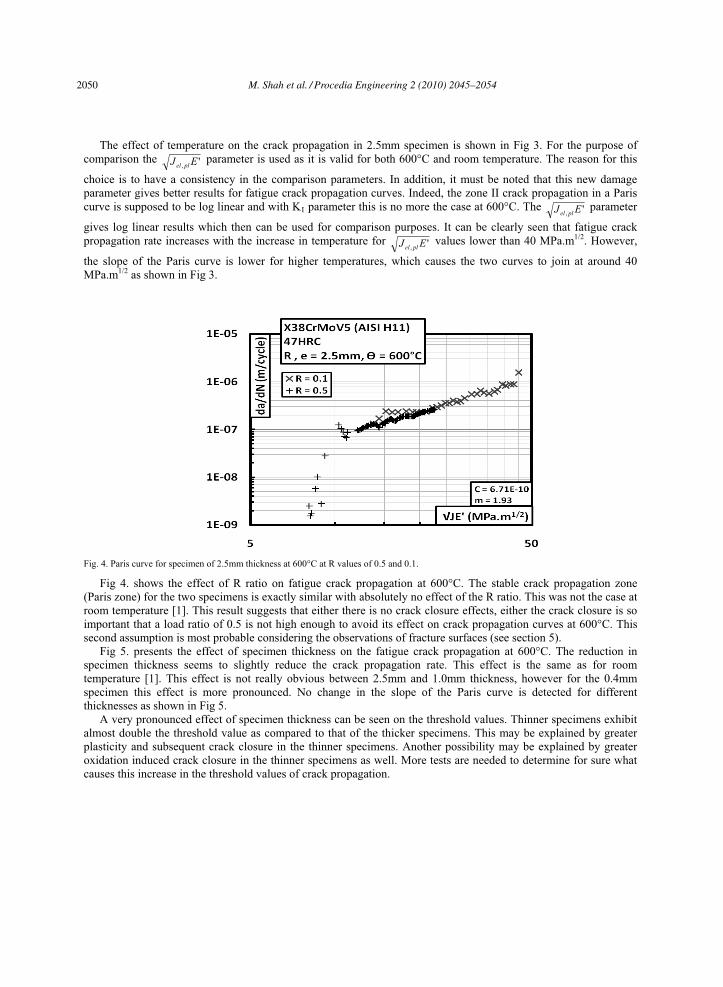
The effect of temperature on the crack propagation in 2.5mm specimen is shown in Fig 3. For the purpose of comparison the ', EJ plel
parameter is used as it is valid for both 600°C and room temperature. The reason for this
choice is to have a consistency in the comparison parameters. In addition, it must be noted that this new damage parameter gives better results for fatigue crack propagation curves. Indeed, the zone II crack propagation in a Paris curve is supposed to be log linear and with KI parameter this is no more the case at 600°C. The ', EJ plel
parameter
gives log linear results which then can be used for comparison purposes. It can be clearly seen that fatigue crack propagation rate increases with the increase in temperature for ', EJ plel
values lower than 40 MPa.m1/2. However,
the slope of the Paris curve is lower for higher temperatures, which causes the two curves to join at around 40 MPa.m1/2 as shown in Fig 3.
Fig. 4. Paris curve for specimen of 2.5mm thickness at 600°C at R values of 0.5 and 0.1.
Fig 4. shows the effect of R ratio on fatigue crack propagation at 600°C. The stable crack propagation zone (Paris zone) for the two specimens is exactly similar with absolutely no effect of the R ratio. This was not the case at room temperature [1]. This result suggests that either there is no crack closure effects, either the crack closure is so important that a load ratio of 0.5 is not high enough to avoid its effect on crack propagation curves at 600°C. This second assumption is most probable considering the observations of fracture surfaces (see section 5).
Fig 5. presents the effect of specimen thickness on the fatigue crack propagation at 600°C. The reduction in specimen thickness seems to slightly reduce the crack propagation rate. This effect is the same as for room temperature [1]. This effect is not really obvious between 2.5mm and 1.0mm thickness, however for the 0.4mm specimen this effect is more pronounced. No change in the slope of the Paris curve is detected for different thicknesses as shown in Fig 5.
A very pronounced effect of specimen thickness can be seen on the threshold values. Thinner specimens exhibit almost double the threshold value as compared to that of the thicker specimens. This may be explained by greater plasticity and subsequent crack closure in the thinner specimens. Another possibility may be explained by greater oxidation induced crack closure in the thinner specimens as well. More tests are needed to determine for sure what causes this increase in the threshold values of crack propagation.
2050 M. Shah et al. / Procedia Engineering 2 (2010) 2045–2054

M. Shah et al./ Procedia Engineering 00 (2010) 000–000 7
Fig. 5. Comparison of fatigue crack propagation at 600°C for different thicknesses.
5. Fractography and microstructure.
It is expected that at elevated temperatures the material may undergo some microstructural modifications. In order to get an insight on these potential modifications and on fatigue crack propagation mechanisms, the specimens have been observed under a conventional filament type electron microscope for fractography and under a FEG microscope for structural analysis.
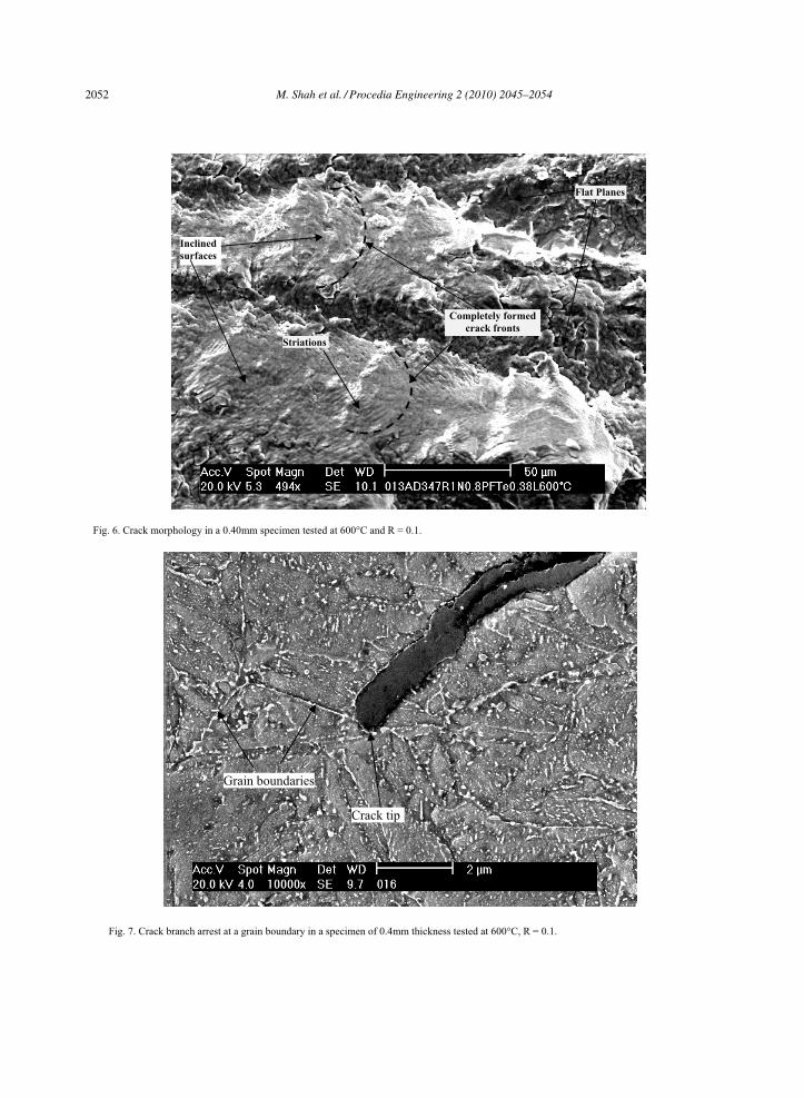
Fractographic analysis reveals two general aspects. One is the inclined planes, where the crack striations are clearly observed. The second is the striation free flat planes. However, the striations can only be seen on the oxide layer and correspond to the rate of crack propagation at that point (1e-6 m/cycle for 35 MPa.m1/2) as shown in Fig 6. The striation directions observed on the inclined surfaces indicate their own completely local crack fronts. The presence of the inclined surface has also been observed at room temperature and has been explained in detail [1]. These observations show therefore a duplex (or double) local cracking mechanism presumably linked to the local crystallographic orientation of grains. The absence of oxide layer on the flat plane indicates also that these surfaces may undergo strong crack closure which breaks the oxide surface. The inclined planes have an un disturbed oxide layer which may indicate an absence or reduction of the local crack closure.
Observations of the profile of the crack shows some interesting facts. Most of the crack propagation at 600°C is branched into the material (Fig 7). At room temperature the frequency of crack branching is very low as compared with that of 600°C. These branches often are stopped by perpendicular martensitic laths or grain boundaries. The branches of the cracks however, are also oxidized, see Fig 7. The testing conditions at 600°C cause an over precipitation at the grain boundaries as can be seen in Fig 7. This type of precipitation, especially along the grain boundaries does not exist in the as heat treated material, see Fig 8.
M. Shah et al. / Procedia Engineering 2 (2010) 2045–2054 2051
8 M. Shah et al./ Procedia Engineering 00 (2010) 000–000
Fig. 6. Crack morphology in a 0.40mm specimen tested at 600°C and R = 0.1.
Fig. 7. Crack branch arrest at a grain boundary in a specimen of 0.4mm thickness tested at 600°C, R = 0.1.
Striations
Completely formed
crack fronts
Flat Planes
Inclined
surfaces
Grain boundaries
Crack tip
2052 M. Shah et al. / Procedia Engineering 2 (2010) 2045–2054

M. Shah et al./ Procedia Engineering 00 (2010) 000–000 9
Fig. 8. Material microstructure (3% Nital etching) in as heat treated condition.
6. Conclusion
Fatigue crack propagation experiments have been performed at 600°C on SENT specimens. A new crack driving force parameter has been calculated by numerical simulation. The analysis of fatigue tests with this parameter has been carried out for room temperature as well as 600°C. The new damage parameter gives better results for fatigue crack propagation curves. Indeed, the zone II crack propagation in a Paris curve is supposed to be log linear and with KI parameter this is no more the case. The ', EJ plel
parameter gives log linear results which then can be used
for comparison purposes. Another advantage of this crack driving force parameter is that it can be uniquely applied to both hot and cold testing, as at room temperature it gives the same values as for the KI parameter.
Having developed a suitable crack driving force parameter, fatigue crack propagation experiments are performed at 600°C. No effect of variation of R ratio was observed in these specimens whereas, in specimens tested at 25°C this effect was clearly visible. The reduction in specimen thickness causes a slight reduction in the crack propagation rate as observed at room temperature.
Comparing results at room and high temperature, it appears that the crack propagation rate at 600°C seems to be higher for ', EJ plel
lower than 40 MPa.m1/2. However, the slope of the Paris [12] curve is lower and the curves seem
to join for values above 40 MPa.m1/2.The material used belongs to a class of precipitation strengthened steels. The heating of the material to high
temperatures causes an over precipitation of carbides, especially on the grain boundaries. The fractographic analysis reveals many flat and inclined planes on the crack surface. Each plane seems to
contain a fully developed crack fronts with fatigue striation visible only on the oxide layer. The crack front is heavily branched. The branches seem to stop often at the grain or lath boundaries.
M. Shah et al. / Procedia Engineering 2 (2010) 2045–2054 2053

10 M. Shah et al./ Procedia Engineering 00 (2010) 000–000
Acknowledgements
The authors would like to acknowledge Aubert & Duval, for providing free of charge, the heat treated testing material used in this investigation. One of the authors, M. Shah would like to acknowledge very much, the Government of Pakistan for the research grant.
References
[1] SHAH M, MABRU C, BOHER C, LEROUX S, REZAI-ARIA F: Crack propagation in tool steel X38CrMoV5 (AISI H11) in SET specimens. Adv. Eng. Mater. 2009; 746-49.
[2] PERSSON, A; BERGSTRÖM, J; BURMAN, C: Evaluation of heat checking damage in die casting, In: 5th International Conference on Tooling, 1999, p. 167-177.
[3] RAMOUS, E; ZAMBON, A; Dies damage in long term die casting of aluminum alloys, In: Proceedings of the 5th International conference on tooling, 1999, p. 179-184.
[4] HONG, Sanki; and WEIL, Rolf: Low cycle fatigue of thin copper foils, In: Thin Solid Films., 283, 1996, p. 175. [5] SCHWAIGER, R; KRAFT, O: High cycle fatigue of thin films investigated by dynamic micro beam deflection, In: Scripta Materialia.,
41, 1999, p. 823–829. [6] SCHWAIGER, R; KRAFT, O; WELLNER, P: Fatigue in thin films: Lifetime and damage formation, In: Mater Sci Eng., 2001, p.919. [7] Unpublished internal results [8] CRAVERO, S; RUGGIERI, C: Estimation procedure of J-resistance curves for SE(T) fracture specimens using unloading compliance,
In: Engineering Fracture Mechanics., 74, 2007, p. 2735-2757. [9] CHIODO, M, S; CRAVERO, S; RUGGIERI, C: Stress intensity factors for SE(T) specimens, Technical report, BT-PNV-68, Faculty of
Engineering, University of São Paulo, 2006. [10] JOHN, R; RIGLING, B: Effect of height to width ratio on K and CMOD solutions for a single edge cracked geometry with clamped
ends, In: Engineering Fracture Mechanics., 60, 1998, p. 147-156. [11] DOWLING, N.E: Geometry effects and the J-Integral approach to elastic plastic fatigue crack growth, In: Cracks and Fracture ASTM
STP601, American Society for Testing and Materials, 1976, p. 19-32. [12] PARIS, P, C; ERDOGAN, F: A critical analysis of crack propagation laws, In: Journal of Basic Engineering., 85, 1963, p. 528-34.
2054 M. Shah et al. / Procedia Engineering 2 (2010) 2045–2054


![CD/CDX - EBARA7 CD_CDX 50Hz MATERIALS TABLE Ref. Name Material 1 Casing AISI 304 / AISI 316 [5] 24 Priming plug AISI 303 / AISI 316 [5] 3 Motor bracket Aluminium 25 Drain plug AISI](https://img.pdfslide.us/doc/110x75/6103836052038a666e315b88/cdcdx-7-cdcdx-50hz-materials-table-ref-name-material-1-casing-aisi-304-aisi.jpg)