Embed Size (px)
Citation preview
Journal of Electrostatics 59 (2003) 3–13
Investigation of corona charge stabilitymechanisms in polytetrafluoroethylene (PTFE)
teflon films after plasma treatment
Qiang Chen*
Institute of Plasma Physics, Chinese Academy of Science, P.O. Box 1126, Hefei, Anhui 230031,
People’s Republic of China
Received 28 June 2002; received in revised form 2 April 2003; accepted 7 April 2003
Abstract
In this paper, the corona charge stability in electret polytetrafluoroethylene Teflon film is
investigated after the film is treated by radio-frequency plasma. It is found that the charge
stability depends strongly on the plasma composition and the film exposure to plasma,
especially for negative charge. When a non-metalized film is held horizontally on the ground
holder, i.e. with one side facing the plasma, oxygen plasma treatment achieves a superior
negative charge retention on the front side, while its rear side retention decreases significantly.
Under the same conditions in oxygen/helium and helium plasmas, the charge stability also
increases but the potentials are lower compared with pure oxygen plasma after annealing. In a
hydrogen plasma, the stability only slightly enhances. If the film is held vertically on the
holder, so that both sides contact the plasma, the surface potential on both sides decreases
dramatically and arrives at a few volts within 2min, after annealing at 170�C. By Fourier
transform infrared (FTIR) and X-ray photoelectron spectroscopy (XPS), we conclude that
oxidation formed on the front side is responsible for increasing the stability of negative charge.
The positive carriers, generated in the film during plasma treatment, recombine with charge
from corona charging and causes the surface potential in the rear side of the horizontal non-
metalized film, or in both sides of the vertical non-metalized film, to discharge after heating.
r 2003 Elsevier Science B.V. All rights reserved.
Keywords: Radio-frequency plasma; Teflon film; Corona charge stability; Electret; FTIR; XPS;
Polytetrafluoroethylene (PTFE)
ARTICLE IN PRESS
*Tel.: +49-6131-379404.
E-mail address: [email protected] (Q. Chen).
0304-3886/03/$ - see front matter r 2003 Elsevier Science B.V. All rights reserved.
doi:10.1016/S0304-3886(03)00067-6
1. Introduction
Plasma treatment has been widely utilized to modify surfaces of polymer films toincrease material adhesion, decrease the liquid contact angle, and improve thecompatibility of materials [1–5]. Compared to chemical treatment, it does notgenerate toxic by-products and is efficient [6,7]. Plasma, electrons, ions and radicalscan etch the surface, change the surface chemical structure or initiate surfacechemical reactions, depending on the plasma composition and energy or thesubstrate conditions. It is well known that the modification of electret surfaces canchange the charge life time (or charge stability) because of the Maxwell–Wagnereffect [8–10], especially on oxidized surface [11–13]. In this work, we employed aradio-frequency (RF) plasma to treat electrets before corona charging in order tofind out how RF plasma treatment affects the corona charge storage.In our experiment, polytetrafluoroethylene (PTFE) films were treated by the same
plasma source, however, some films were held horizontally on the grounded holderto treat only one side of the film while others were held vertically to expose bothsurfaces. After treatment, the film was charged at room temperature by a needle-to-plant system, a conventional method of corona charging. Then at 170�C isothermalor elevated temperature, the surface-potential decay rate was measured to determinethe effect of plasma treatment on charge stability.There are several ways that plasma treatment could affect film surface charge.
Plasma treated films can generate space charge in the body due to electron, ion andcharged radicals impacting and penetrating the film. Also, the UV irradiation couldbe crucial. Sapieha [14] even found that the charge polarity on the treated filmdepended on the film location; a negative signal on the surface appeared when thefilm was placed on the grounded electrode, and a positive signal appeared whenthe film was placed at the RF electrode. Amyot [15] once polymerized and charged theelectret in a plasma at the same time. Nunes da Cunha [16] confirmed the positiveinjection into an electret from UV light. How these charges from an RF plasmainfluence the corona charge stability is not yet exactly clear. In this paper, we investigatethe possibility that these changes are due to plasma ions interacting with the film.The surface structure of the PTFE film after plasma treatment was analyzed by Fourier
transform infrared (FTIR) as well as X-ray photoelectron spectroscopy (XPS). The FTIR(Nicolet 850) spectra were taken of the bulk film to reveal the functional groups on thesurface. To quantitatively explore the film surface, XPS was used. By measuring the C-1sand O-1s XPS spectra, the fluorine to carbon ratio (F/C) as well as oxygen to carbon ratio(O/C) were derived from distribution among CF3, CF2, CF–C=O, C–O, etc. groups. Thedetailed knowledge of the treated film allowed us to evaluate the film surface structure,properties and thereby determine the treatment mechanism.
2. Experiment
The plasma treatment was carried out in a pyrex glass chamber (16 cm diameter,40 cm height) with capacitively coupled outside electrodes using 20W of 13.56MHz
ARTICLE IN PRESSQ. Chen / Journal of Electrostatics 59 (2003) 3–134
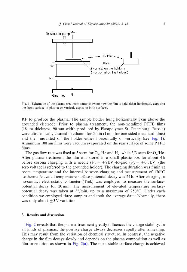
RF to produce the plasma. The sample holder hung horizontally 3 cm above thegrounded electrode. Prior to plasma treatment, the non-metalized PTFE films(18 mm thickness, 90mm width produced by Plastpolymer St. Petersburg, Russia)were ultrasonically cleaned in ethanol for 5min (1min for one-sided metalized films)and then mounted on the holder either horizontally or vertically (see Fig. 1).Aluminum 100 nm films were vacuum evaporated on the rear surface of some PTFEfilms.The gas flow rate was fixed at 5 sccm for O2, He and H2, while 3/3 sccm for O2/He.
After plasma treatment, the film was stored in a small plastic box for about 4 hbefore corona charging with a needle (Vn ¼ 78 kV)-to-grid (Vg ¼ 70:5 kV) (thezero voltage is referred to the grounded holder). The charging duration was 5min atroom temperature and the interval between charging and measurement of 170�Cisothermal/elevated temperature surface-potential decay was 24 h. After charging, ano-contact electrostatic voltmeter (Trek) was employed to measure the surface-potential decay for 20min. The measurement of elevated temperature surface-potential decay was taken at 3�/min, up to a maximum of 250�C. Under eachcondition we employed three samples and took the average data. Normally, therewas only about 73V variation.
3. Results and discussion
Fig. 2 reveals that the plasma treatment greatly influences the charge stability. Inall kinds of plasmas, the positive charge always decreases rapidly after annealing.This may result from the variation of chemical structure. In contrast, the negativecharge in the film decays slowly and depends on the plasma composition as well asfilm orientation as shown in Fig. 2(a). The most stable surface charge is achieved
ARTICLE IN PRESS
Fig. 1. Schematic of the plasma treatment setup showing how the film is held either horizontal, exposing
the front surface to plasma or vertical, exposing both surfaces.
Q. Chen / Journal of Electrostatics 59 (2003) 3–13 5
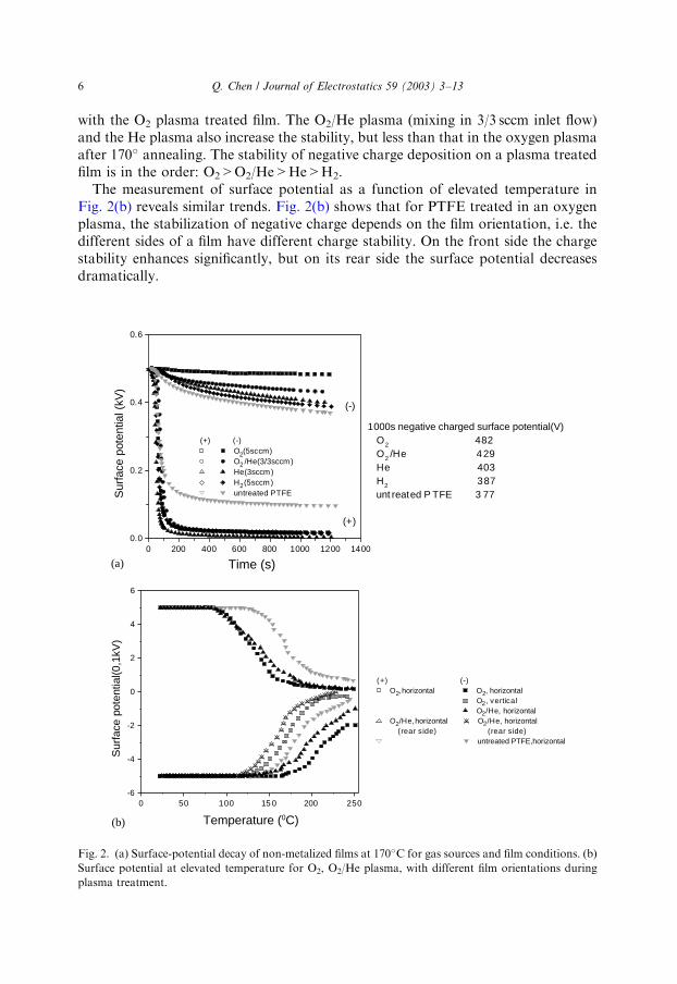
with the O2 plasma treated film. The O2/He plasma (mixing in 3/3 sccm inlet flow)and the He plasma also increase the stability, but less than that in the oxygen plasmaafter 170� annealing. The stability of negative charge deposition on a plasma treatedfilm is in the order: O2>O2/He>He>H2.The measurement of surface potential as a function of elevated temperature in
Fig. 2(b) reveals similar trends. Fig. 2(b) shows that for PTFE treated in an oxygenplasma, the stabilization of negative charge depends on the film orientation, i.e. thedifferent sides of a film have different charge stability. On the front side the chargestability enhances significantly, but on its rear side the surface potential decreasesdramatically.
ARTICLE IN PRESS
0 200 400 600 800 1000 1200 14000.0
0.2
0.4
0.6
1000s negative charged surface potential(V) O2 482 O2 /He 429 He 403 H2 387 unt reated P TFE 3 77
(-)
(+)
(+) (-)O2(5sccm)O2 /He(3/3sccm)He(3sccm)H2(5sccm)untreated PTFES
urfa
ce p
oten
tial (
kV)
Time (s)
0 50 100 15 0 200 250-6
-4
-2
0
2
4
6
(+) (-)O2, horizontal O2, horizontal
O2, verticalO2/He, horizontal
O2/He, horizontal O2/He, horizontal (rear side) (rear side)
untreated PTFE,horizontal
Sur
face
pot
entia
l(0,1
kV)
Temperature (0C)
(a)
(b)
Fig. 2. (a) Surface-potential decay of non-metalized films at 170�C for gas sources and film conditions. (b)
Surface potential at elevated temperature for O2, O2/He plasma, with different film orientations during
plasma treatment.
Q. Chen / Journal of Electrostatics 59 (2003) 3–136
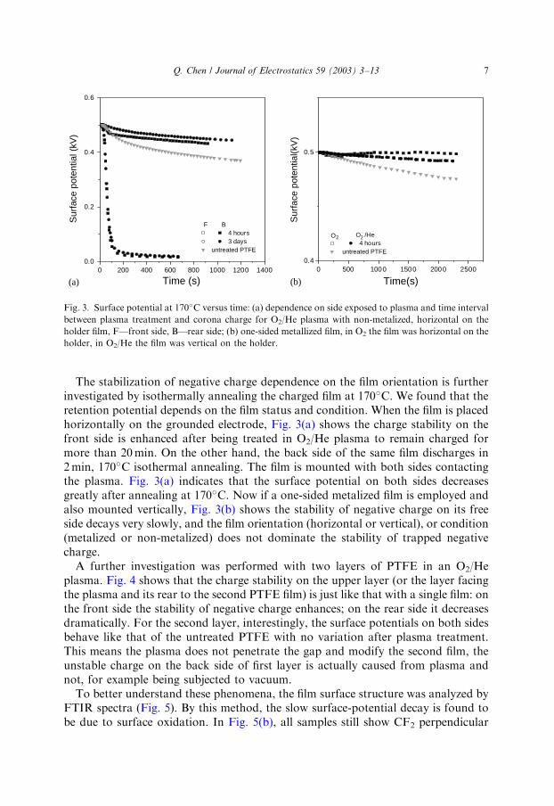
The stabilization of negative charge dependence on the film orientation is furtherinvestigated by isothermally annealing the charged film at 170�C. We found that theretention potential depends on the film status and condition. When the film is placedhorizontally on the grounded electrode, Fig. 3(a) shows the charge stability on thefront side is enhanced after being treated in O2/He plasma to remain charged formore than 20min. On the other hand, the back side of the same film discharges in2min, 170�C isothermal annealing. The film is mounted with both sides contactingthe plasma. Fig. 3(a) indicates that the surface potential on both sides decreasesgreatly after annealing at 170�C. Now if a one-sided metalized film is employed andalso mounted vertically, Fig. 3(b) shows the stability of negative charge on its freeside decays very slowly, and the film orientation (horizontal or vertical), or condition(metalized or non-metalized) does not dominate the stability of trapped negativecharge.A further investigation was performed with two layers of PTFE in an O2/He
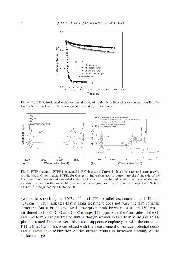
plasma. Fig. 4 shows that the charge stability on the upper layer (or the layer facingthe plasma and its rear to the second PTFE film) is just like that with a single film: onthe front side the stability of negative charge enhances; on the rear side it decreasesdramatically. For the second layer, interestingly, the surface potentials on both sidesbehave like that of the untreated PTFE with no variation after plasma treatment.This means the plasma does not penetrate the gap and modify the second film, theunstable charge on the back side of first layer is actually caused from plasma andnot, for example being subjected to vacuum.To better understand these phenomena, the film surface structure was analyzed by
FTIR spectra (Fig. 5). By this method, the slow surface-potential decay is found tobe due to surface oxidation. In Fig. 5(b), all samples still show CF2 perpendicular
ARTICLE IN PRESS
0 500 1000 1500 2000 25000.4
0.5
O2 O2 /He4 hours
untreated PTFE
Sur
face
pot
entia
l(kV
)Time(s)
0 200 400 600 800 1000 1200 14000.0
0.2
0.4
0.6
F B4 hours3 days
untreated PTFE
Sur
face
pot
entia
l (kV
)
Time (s)(a) (b)
Fig. 3. Surface potential at 170�C versus time: (a) dependence on side exposed to plasma and time interval
between plasma treatment and corona charge for O2/He plasma with non-metalized, horizontal on the
holder film, F—front side, B—rear side; (b) one-sided metallized film, in O2 the film was horizontal on the
holder, in O2/He the film was vertical on the holder.
Q. Chen / Journal of Electrostatics 59 (2003) 3–13 7
symmetric stretching at 1207 cm�1 and CF2 parallel asymmetric at 1152 and1242 cm�1. This indicates that plasma treatment does not vary the film intrinsicstructure. But a broad and weak absorption peak between 1410 and 1800 cm�1,attributed to C=O, C–O and C=C groups [17] appears on the front sides of the O2
and O2/He mixture gas treated film, although weaker in O2/He mixture gas. In H2
plasma treated film, however, this peak disappears completely, as with the untreatedPTFE (Fig. 5(a)). This is correlated with the measurement of surface-potential decayand suggests that oxidization of the surface results in increased stability of thesurface charge.
ARTICLE IN PRESS
0 200 400 600 800 1000 1200 14000.0
0.2
0.4
0.6
F B4h, first layer4h, second layer3days, first layer 3days, second layer
unteated PTFE
Sur
face
pot
entia
l(kV
)
Time (s)
Fig. 4. The 170�C isothermal surface-potential decay of double layer films after treatment in O2/He, F—
front side, B—back side. The film oriented horizontally on the holder.
3000 2500 2000 1500 1000
0
4
8
12
16
54
32
1
Abs
orbt
ion
(a.u
.)
Wavenumber (cm-1)
1
20*
1-horizontal on the holder (front side)2-veritcal on theholder freeside (one-sided metalized)3-vertical on theholder (one side)4-vertical on theholder (rearside)5-no plasmatreatment
3000 2500 2000 1500
4
3
2
1
20*
1-O22-O2 /He3-H24-no plasma treatment
Abs
orbt
ion
(a.u
.)
Wavenumber (cm-1) (b)(a)
Fig. 5. FTIR spectra of PTFE film treated in RF plasma. (a) Curves in figure from top to bottom are O2,
O2/He, H2, and non-treated PTFE. (b) Curves in figure from top to bottom are the front side of the
horizontal film, free side of one-sided metalized but vertical on the holder film, two sides of the non-
metalized vertical on the holder film, as well as the original non-treated film. The range from 2800 to
1300 cm�1 is magnified by a factor of 20.
Q. Chen / Journal of Electrostatics 59 (2003) 3–138
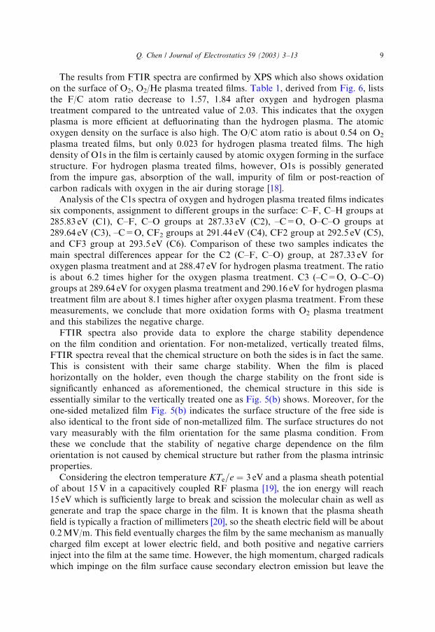
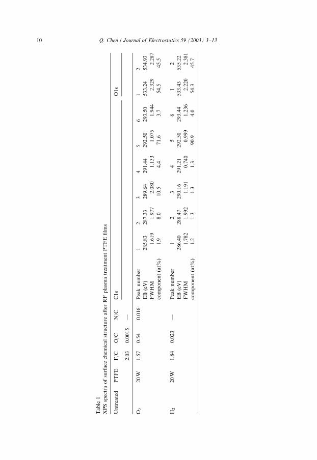
The results from FTIR spectra are confirmed by XPS which also shows oxidationon the surface of O2, O2/He plasma treated films. Table 1, derived from Fig. 6, liststhe F/C atom ratio decrease to 1.57, 1.84 after oxygen and hydrogen plasmatreatment compared to the untreated value of 2.03. This indicates that the oxygenplasma is more efficient at defluorinating than the hydrogen plasma. The atomicoxygen density on the surface is also high. The O/C atom ratio is about 0.54 on O2
plasma treated films, but only 0.023 for hydrogen plasma treated films. The highdensity of O1s in the film is certainly caused by atomic oxygen forming in the surfacestructure. For hydrogen plasma treated films, however, O1s is possibly generatedfrom the impure gas, absorption of the wall, impurity of film or post-reaction ofcarbon radicals with oxygen in the air during storage [18].Analysis of the C1s spectra of oxygen and hydrogen plasma treated films indicates
six components, assignment to different groups in the surface: C–F, C–H groups at285.83 eV (C1), C–F, C–O groups at 287.33 eV (C2), –C=O, O–C–O groups at289.64 eV (C3), –C=O, CF2 groups at 291.44 eV (C4), CF2 group at 292.5 eV (C5),and CF3 group at 293.5 eV (C6). Comparison of these two samples indicates themain spectral differences appear for the C2 (C–F, C–O) group, at 287.33 eV foroxygen plasma treatment and at 288.47 eV for hydrogen plasma treatment. The ratiois about 6.2 times higher for the oxygen plasma treatment. C3 (–C=O, O–C–O)groups at 289.64 eV for oxygen plasma treatment and 290.16 eV for hydrogen plasmatreatment film are about 8.1 times higher after oxygen plasma treatment. From thesemeasurements, we conclude that more oxidation forms with O2 plasma treatmentand this stabilizes the negative charge.FTIR spectra also provide data to explore the charge stability dependence
on the film condition and orientation. For non-metalized, vertically treated films,FTIR spectra reveal that the chemical structure on both the sides is in fact the same.This is consistent with their same charge stability. When the film is placedhorizontally on the holder, even though the charge stability on the front side issignificantly enhanced as aforementioned, the chemical structure in this side isessentially similar to the vertically treated one as Fig. 5(b) shows. Moreover, for theone-sided metalized film Fig. 5(b) indicates the surface structure of the free side isalso identical to the front side of non-metallized film. The surface structures do notvary measurably with the film orientation for the same plasma condition. Fromthese we conclude that the stability of negative charge dependence on the filmorientation is not caused by chemical structure but rather from the plasma intrinsicproperties.Considering the electron temperature KTe=e ¼ 3 eV and a plasma sheath potential
of about 15V in a capacitively coupled RF plasma [19], the ion energy will reach15 eV which is sufficiently large to break and scission the molecular chain as well asgenerate and trap the space charge in the film. It is known that the plasma sheathfield is typically a fraction of millimeters [20], so the sheath electric field will be about0.2MV/m. This field eventually charges the film by the same mechanism as manuallycharged film except at lower electric field, and both positive and negative carriersinject into the film at the same time. However, the high momentum, charged radicalswhich impinge on the film surface cause secondary electron emission but leave the
ARTICLE IN PRESSQ. Chen / Journal of Electrostatics 59 (2003) 3–13 9
ARTICLE IN PRESS
Table1
XPSspectraofsurface
chem
icalstructure
after
RFplasm
atreatm
entPTFEfilms
Untreated
PTFE
F/C
O/C
N/C
C1s
O1s
2.03
0.0015
—
O2
20W
1.57
0.54
0.016
Peaknumber
12
34
56
12
EB(eV)
285.83
287.33
289.64
291.44
292.50
293.50
533.24
534.93
FWHM
1.619
1.977
2.080
1.133
1.075
1.944
2.329
2.287
component(at%
)1.9
8.0
10.5
4.4
71.6
3.7
54.5
45.5
H2
20W
1.84
0.023
—Peaknumber
12
34
56
12
EB(eV)
286.40
288.47
290.16
291.21
292.50
293.44
533.43
535.22
FWHM
1.782
1.992
1.191
0.740
0.999
1.236
2.220
2.381
component(at%
)1.2
1.3
1.3
1.3
90.9
4.0
54.3
45.7
Q. Chen / Journal of Electrostatics 59 (2003) 3–1310
parent positive carriers in the film. These charged carriers remaining in the film bodywill influence the stability of sequential corona charge.Besides electron, ion, as well as charged radicals injected into the film and forming
space charge in the film, UV light from plasma can also generate the charge in thefilm. The energetic photoradiation can alter the chemical structure by chain scission,cross-linking and give rise to the presence of the trapped charge within the materials.Due to the rapid mobility caused by the variation of the surface chemical
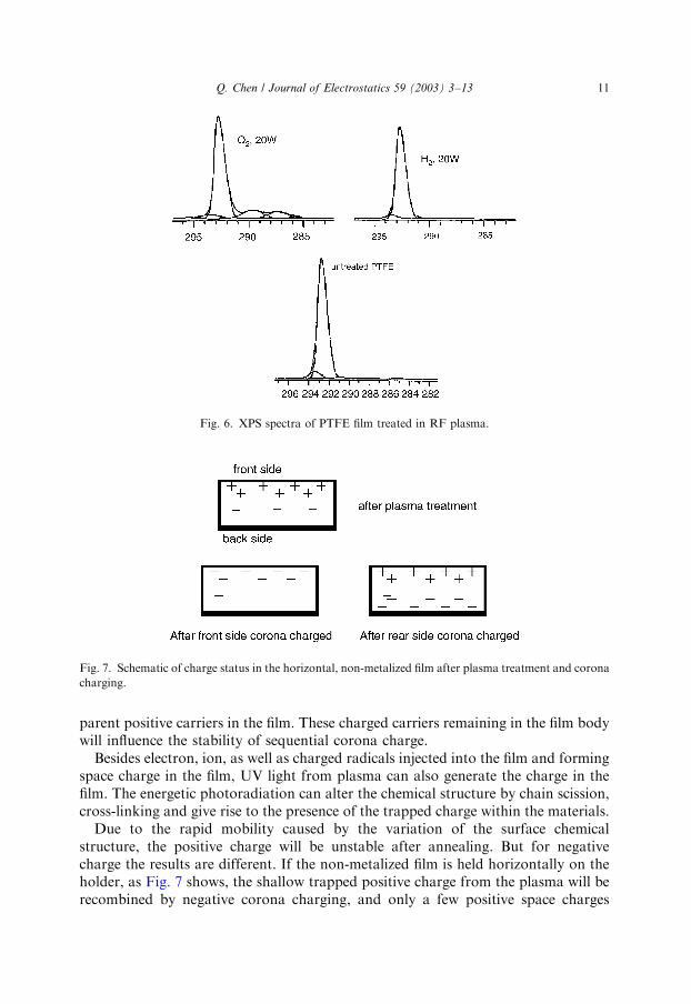
structure, the positive charge will be unstable after annealing. But for negativecharge the results are different. If the non-metalized film is held horizontally on theholder, as Fig. 7 shows, the shallow trapped positive charge from the plasma will berecombined by negative corona charging, and only a few positive space charges
ARTICLE IN PRESS
Fig. 7. Schematic of charge status in the horizontal, non-metalized film after plasma treatment and corona
charging.
Fig. 6. XPS spectra of PTFE film treated in RF plasma.
Q. Chen / Journal of Electrostatics 59 (2003) 3–13 11
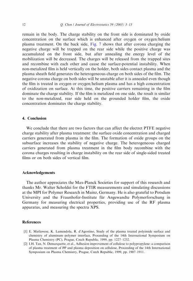
remain in the body. The charge stability on the front side is dominated by oxideconcentration on the surface which is enhanced after oxygen or oxygen/heliumplasma treatment. On the back side, Fig. 7 shows that after corona charging thenegative charge will be trapped on the rear side while the positive charge wasaccumulated on the front side, but after annealing the energy level of themobilization will be decreased. The charges will be released from the trapped sitesand recombine with each other and cause the surface-potential instability. Whennon-metalized film is held vertically on the holder, both sides contact plasma and theplasma sheath field generates the heterogeneous charge on both sides of the film. Thenegative corona charge on both sides will be unstable after it is annealed even thoughthe film is treated in oxygen or oxygen/helium plasma and has a high concentrationof oxidization on surface. At this time, the positive carriers remaining in the filmdominate the charge stability. If the film is metalized on one side, the result is similarto the non-metalized, rear side held on the grounded holder film, the oxideconcentration dominates the charge stability.
4. Conclusion
We conclude that there are two factors that can affect the electret PTFE negativecharge stability after plasma treatment: the surface oxide concentration and chargedcarriers generated from plasma in the film. The formation of oxide groups on thesubsurface increases the stability of negative charge. The heterogeneous chargedcarriers generated from plasma treatment in the film body recombine with thecorona charges resulting in charge instability on the rear side of single-sided treatedfilms or on both sides of vertical film.
Acknowledgements
The author appreciates the Max-Planck Societies for support of this research andthanks Mr. Walter Scholdei for the FTIR measurements and simulating discussionsat the MPI for Polymer Research in Mainz, Germany. He is also grateful to PotsdamUniversity and the Fraunhofer-Institute f .ur Angewandte Polymerforschung inGermany for measuring electrical properties, providing use of the RF plasmaapparatus, and measuring the spectra XPS.
References
[1] E. Matlawese, K. Lamendola, R. d’Agostino, Study of the plasma treated polyimide surface and
chemistry of aluminum–polymer interface, Proceeding of the 14th International Symposium on
Plasma Chemistry (PC), Prague, Czech Republic, 1999, pp. 1227–1232.
[2] I.H. Tan, N. Demarquette, et al., Adhesion improvement of cellulose to polypropylene: a comparison
of plasma treatment of PP and plasma deposition on cellulose, Proceeding of the 14th International
Symposium on Plasma Chemistry, Prague, Czech Republic, 1999, pp. 1907–1911.
ARTICLE IN PRESSQ. Chen / Journal of Electrostatics 59 (2003) 3–1312
[3] R. Seeb .ock, H. Esrom, M. Charbonnier, M. Romand, Modification of polyimide in barrier discharge
air-plasmas: chemical and morphological effect, Plasma Polym. 5 (2000) 103–118.
[4] R. Winter, D. Korzec, N. Sprang, et al., Broad pressure range PTFE surface modification with slot
antenna microwave discharge, in: 94 International Plasma Surface Engineering Proceeding (PSE),
Germany, 1994, pp. 618–624.
[5] M.S. Kang, B. Chun, S.S. Kim, Surface modification of polypropylene membrane by low-
temperature plasma treatment, J. Appl. Polym. Sci. 81 (2001) 1555–1566.
[6] M. Strobel, C.S. Lyons, K.L. Mittal (Eds.), Plasma Surface Modification of Polymer: Relevance to
Adhesion, VSP, Utecht, 1994, pp. 10–45.
[7] M. Moisan, J. Pelletier (Eds.), Microwave Excited Plasma, Elsevier, Amsterdam, 1992, pp. 2–10.
[8] A.A. Rychkov, V.G. Boitsov, Charge relation of PTFE-Al structures having interfacial region
modified by the glow discharge, The 10th International Symposium on Electrets (ISE), Greece, 1999,
pp. 91–94.
[9] W. K .unstler, P. Fr .ubing, R. Gerharder-Multhaupt, et al., Surface charging behaviors of plasma
treated polymer film, 1998 IEEE Annual Report CEIDP, Atlanta, 1998, pp. 609–612.
[10] G. Sessler (Ed.), Electret, Vol. 1, 3rd Edition, Laplacian Press, Morgan Hill, CA, 1999, pp. 66–70.
[11] W. Stark, R. Danz, W. K .unstler, D. Geiss, Influence and implication of surface contamination on the
charge decay in electrets, Proceeding of the Sixth International Symposium on Electrets, Oxford,
England, 1988, pp. 389–393.
[12] S. Haridoss, M.M. Perlman, Chemical modification of near-surface charge trapping in polymer,
J. Appl. Phys. 55 (1984) 1332–1338.
[13] G. Chen, A.E. Davies, et al., Influence of radiation environment on space charge formation in
g-irradiated LDPE, IEEE Trans. Dielectr. Electr. Insul. 6 (1999) 882–886.
[14] S. Sapieha, J.E. Klemberg-Saphieha, et al., Plasma polymer electrets, Proceedings of the Fifth
International Symposium on Electrets, New York, USA, 1985, pp. 571–577.
[15] N. Amyot, J.E. Klemberg-Sapicha, M.R. Wertheimer, Electrical and structural studies of plasma
polymerized fluorocarbon films, IEEE Trans. Electr. Insul. 27 (1992) 1101–1107.
[16] H. Nunes da Cunha, R.A. Moreno, Thermally stimulated discharge and heat pulse responses of UV
irradiated corona charged Teflon FEP films, Proceedings of the Seventh International Symposium on
Electrets, Berlin, Germany, 1990, pp. 61–66.
[17] S.J. limb, K.K.S. Lau, D.J. Edell, E.F. Gleason, K. Gleason, Molecular design of fluorocarbon film
architecture by pulsed plasma enhanced and pyrolytic chemical vapor deposition, Plasma Polym. 4
(1999) 21–32.
[18] N. Sprang, D. Theirich, J. Engamann, Plasma and ion beam surface treatment of polyethylene, in: 94
International Plasma Surface Engineering Proceeding (PSE), Germany, 1994, pp. 689–695.
[19] J. Friedrich, L. Wigant, W. Unger, A. Lippitz, H. Wittrich, Corona, spark and combined UV and
ozone modification of polymer film WeBP23, Surf. Coat. Technol. 98 (1998) 879–885.
[20] B. Chapman, Glow Discharge Processes, Wiley, New York, 1980, pp. 24–45.
ARTICLE IN PRESSQ. Chen / Journal of Electrostatics 59 (2003) 3–13 13