Embed Size (px)
DESCRIPTION
Investigation Into the Impact of Agility in Conceptual Fighter Design
Citation preview
NASA Contractor Report 195079
lit', ", ;
dm_ 7-7
Investigation Into the Impact ofConceptual Fighter Design
Agility in
R. M. Engelbeck
Boeing Defense & Space Group, Seattle, Washington
(NASA-CR-195079) INVESTIGATIONINTO THE IMPACT OF AGILITY ON
CONCEPTUAL FIGHTER DESIGN (Boeing
Defense and Space Group) 19i p
N96-10737
Unclas
G3/05 0063497
Contract NAS1-18762
June 1995
National Aeronautics and
,Space Administration
Langley Research Center
Hampton, Virginia 23681-0001


PREFACE
The work reported here represents the final report for NASA Langley contract NAS1-18762 Spacecraft &Aircraft Guidance and Control Task 22, Agility Design Study.
The NASA Project Engineer was M. J. Logan, and the Boeing Principal Investigator was R. M. Engelbeck.
ACKNOWLEDGMENTS
The authors would liketo recognize the contributionsmade by all the people at Boeing who made thiswork possible:
B. Ray Stability and Control Engineer
Helped break the conceptual design barrier
P. GotliebG. Letsinger
-- Stability and Control Engineerm Stability and Control Engineer
Agility implementation issues
S. Bockmeyer Aerodynamics Tech Aide
Graphic art and document publication
D. Bock Aerodynamics Engineer
Sizing and Performance
W. Mannick -- Weights Engineer
Weights and Technology Assessment
W. MooreDJRuzicka
Configuration EngineerConfiguration Engineer
ii
3.0
4.0
TABLE OF CONTENTS
5.0
Introduction and Summary ................................................................................................. 1
Study Requirements and Guidelines ................................................................................ .'62.1 Design Mission Profiles ......................................................................................... 6
Air Interdiction Mission Description ........................................................................ 6Air Superiority Mission Description ........................................................................ 6Multi-Role Mission Description .............................................................................. 6
2.2 Maneuver Performance Requirements ................................................................. 10Air Interdiction Maneuver Requirements .............................................................. 10Air Superiority and Multi-Role Maneuver Requirements ...................................... 10
2.3 Agility Requirements ............................................................................................ 102.4 Observables Requirements ................................................................................ 102.5 Carrier Suitability Requirements .......................................................................... 10
Technology Risk Assessment ......................................................................................... 153.1 Technology Risk Assessment Approach ............................................................ 153.2 Technologies Used in Agility Study Configurations ............................................ 373.3 Weight and Cost Impact of Advanced Technologies .......................................... 37
Configuration Development ............................................................................................. 474.1 Assumptions and Groundrules ............................................................................ 47
Single Crew ......................................................................................................... 47Twin Engine ......................................................................................................... 47F-22 Core Avionics Suite .................................................................................... 47Observables Features ........................................................................................ 49Control Effector Selection .................................................................................... 50
4.2 Carrier Suitability Impact on Aircraft Designs ...................................................... 51Geometric Limitations ........................................................................................... 51Weight Limitations ................................................................................................ 51Landing Gear Design ........................................................................................... 51Wing and Fuselage Structural Reinforcement ...................................................... 51
4.3 Designing for Agility ............................................................................................. 554.3.1 Agility Metrics ........................................................................................... 554.3.2 Preliminary Design Guidelines ................................................................. 594.3.3 Method Development .............................................................................. 62
4.3.3.1 Time to Bank and Capture - 90 Degree ................................... 624.3.3.2 Longitudinal Control Requirements ........................................... 64
4.3.3.2.1 Minimum Nose Down Pitch Acceleration ................. 664.3.3.2.2 Maximum TrimmableAngle-of-Attack ...................... 67
4.3.3.3 Maximum Lateral Side Force ..................................................... 674.3.4 Configuration Evaluation ......................................................................... 73
4.3.4.1 Agility Impact on Low Observable Configurations .................. 734.3.4.2 Observables Impact of High Agility Design ............................. 73
4.3.5 Summary
Configuration Synthesis Results ................................................................................ 825.1 Global Impact of Requirements on Design Space .............................................. 825.2 Aircraft Synthesis Results ................................................................................ 86
5.2.1 Air-to-Ground Configurations ................................................................... 865.2.2 Air-to-Air Configurations ........................................................................... 895.2.3 Multi-Role Configurations ........................................................................ 895.2.4 Joint Service Customer ........................................................................... 97
..°
III
6.0
7.0
8.0
Aircraft Design Data and Performance ........................................................................... 1026.1 Air Interdiction Concepts .............................................................................. 1026.2 Air Superiority Concepts .............................................................................. 1146.3 Multi-Role Concepts .............................................................................. 139
Critical Assessment o°o .... oooo° .......... o°o°°oo ............. oo°°oooo ............ ooooo°o°o°°oo°°o163
Flight Research Needs Assessment ............................................................................. 175
iv
1.11.21.31.42.12.22.32.4
"2.52.62.73.1-13.1-23.23.33.43.53.63.73.83.93.103.113.123.133.143.153.163.173.183.194.14.24.34.44.54.64.74.84.94.104.114.124.134.144.15 °4.164.174.184.194.205.1
5.2
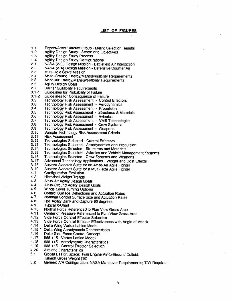
LIST OF FIGURE_;
Fighter/Attack Aircraft Group - Metric Selection ResultsAgility Design Study - Scope and ObjectivesAgility Design Study ProcessAgility Design Study ConfigurationsNASA (NG) Design Mission - Battlefield Air InterdictionNASA (NA) Design Mission - Defensive Counter AirMulti-Role Strike Mission
Air-to-Ground Energy/Maneuverability RequirementsAir-to-Air Energy/Maneuverability RequirementsAgility Design GoalsCarder Suitability RequirementsGuidelines for Probability of FailureGuidelines for Consequence of FailureTechnology Risk Assessment - Control EffectorsTechnology Risk Assessment - AerodynamicsTechnology Risk Assessment - PropulsionTechnology Risk Assessment - Structures & MaterialsTechnology Risk Assessment - AvionicsTechnology Risk Assessment - VMS TechnologiesTechnology Risk Assessment - Crew SystemsTechnology Risk Assessment - WeaponsSample Technology Risk Assessment CriteriaRisk Assessment
Technologies Selected - Control EffectorsTechnologies Selected - Aerodynamics and PropulsionTechnologies Selected - Structures and MaterialsTechnologies Selected - Avionics and Vehicle Management SystemsTechnologies Selected - Crew Systems and WeaponsAdvanced Technology Applications - Weight and Cost EffectsAustere Avionics Suite for an Air-to-Air Agile FighterAustere Avionics Suite for a Multi-Role Agile FighterConfiguration EvolutionHistorical Weight TrendsAir-to-Air Agility Design GoalsAir-to-Ground Agility Design GoalsWings Level Turning OptionsControl Surface Deflections and Actuation RatesNominal Control Surface Size and Actuation Rates
Roll Agility Bank and Capture 90 degreesTypical X-ChartNormal Force Referenced to Plan View Gross AreaCenter of Pressure Referenced to Plan View Gross AreaSide Force Control Effector Selection
Side Force Control Effector Effectiveness with Angle-of-AttackDelta Wing Vortex Lattice ModelDelta Wing Aerodynamic CharacteristicsDelta Side Force Control Concept988-115 Vortex Lattice Model988-115 Aerodynamic Characteristics988-115 Control Effector Selection
Airplane CharacteristicsGlobal Design Space; Twin Engine Air-to-Ground Deltoid;Takeoff Gross Weight (16)Generic A/A Configuration; NASA Maneuver Requirements; T/W Required
v
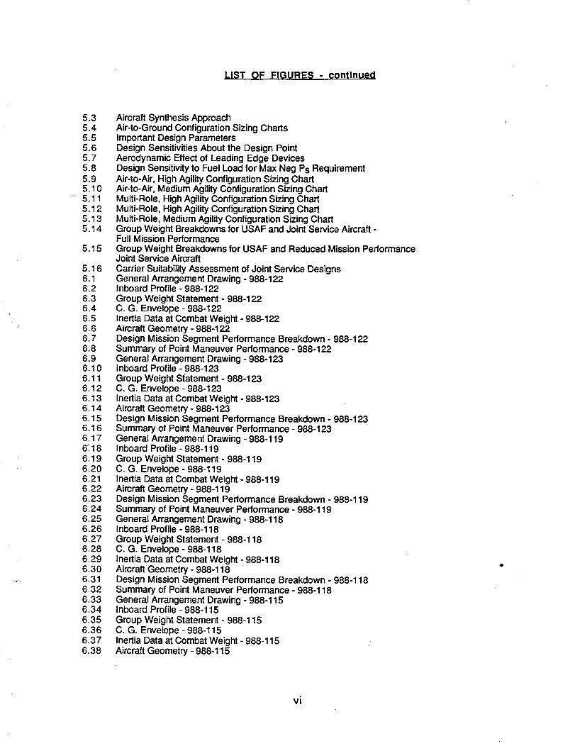
LIST OF FIGURES - continued
5.35.45.55.65.75.8
5.95.10
" 5.115.125.135.14
5.15
5.166.16.26.36.46.56.66.76.86.96.106.116.126.136.146.156.166.176;186.196.206.216.226.236.246.256.266.276.286.296.306.316.326.336.346.356.366.376.38
Aircraft Synthesis ApproachAir-to-Ground Configuration Sizing ChartsImportant Design ParametersDesign Sensitivities About the Design PointAerodynamic Effect of Leading Edge DevicesDesign Sensitivity to Fuel Load for Max Neg Ps Requirement
Air-to-Air, High Agility Configuration Sizing ChartAir-to-Air, Medium Agility Configuration Sizing ChartMulti-Role, High Agility Configuration Sizing ChartMulti-Role, High Agility Configuration Sizing ChartMulti-Role, Medium Agility Configuration Sizing ChartGroup Weight Breakdowns for USAF and Joint Service Aircraft -Full Mission PerformanceGroup Weight Breakdowns for USAF and Reduced Mission PerformanceJoint Service Aircraft
Carrier Suitability Assessment of Joint Service DesignsGeneral Arrangement Drawing - 988-122Inboard Profile - 988-122
Group Weight Statement - 988-122C. G. Envelope - 988-122Inertia Data at Combat Weight - 988-122Aircraft Geometry - 988-122Design Mission Segment Performance Breakdown - 988-122Summary of Point Maneuver Performance - 988-122General Arrangement Drawing - 988-123Inboard Profile - 988-123
Group Weight S{atement - 988-123C. G. Envelope - 988-123Inertia Data at Combat Weight - 988-123Aircraft Geometry - 988-123Design Mission Segment Performance Breakdown - 988-123Summary of Point Maneuver Performance - 988-123
General Arrangement Drawing - 988-119Inboard Profile - 988-119
Group Weight Statement - 988-119C. G. Envelope - 988-119Inertia Data at Combat Weight - 988-119Aircraft Geometry - 988-119Design Mission Segment Performance Breakdown - 988-119Summary of Point Maneuver Performance - 988-119General Arrangement Drawing - 988-118Inboard Profile - 988-118
Group Weight Statement - 988-118C. G. Envelope - 988-118Inertia Data at Combat Weight - 988-118Aircraft Geometry - 988-118Design Mission Segment Performance Breakdown - 988-118Summary of Point Maneuver Performance - 988-118General Arrangement Drawing - 988-115Inboard Profile - 988-115
Group Weight Statement - 988-115C. G. Envelope - 988-115Inertia Data at Combat Weight - 988-115Aircraft Geometry - 988-115
vi
LIST OF FIGURES - continued
6.396.406.416.426.436.446.45
6.46" 6.47
6.48
Design Mission Segment Performance Breakdown - 988-115Summary of Point Maneuver Performance - 988-115General Arrangement Drawing - 988-114Inboard Profile - 988-114
Group Weight Statement - 988-114C. G. Envelope - 988-114Inertia Data at Combat Weight - 988-114Aircraft Geometry - 988-114Design Mission Segment Performance Breakdown - 988-114Summary of Point Maneuver Performance - 988-114
vii

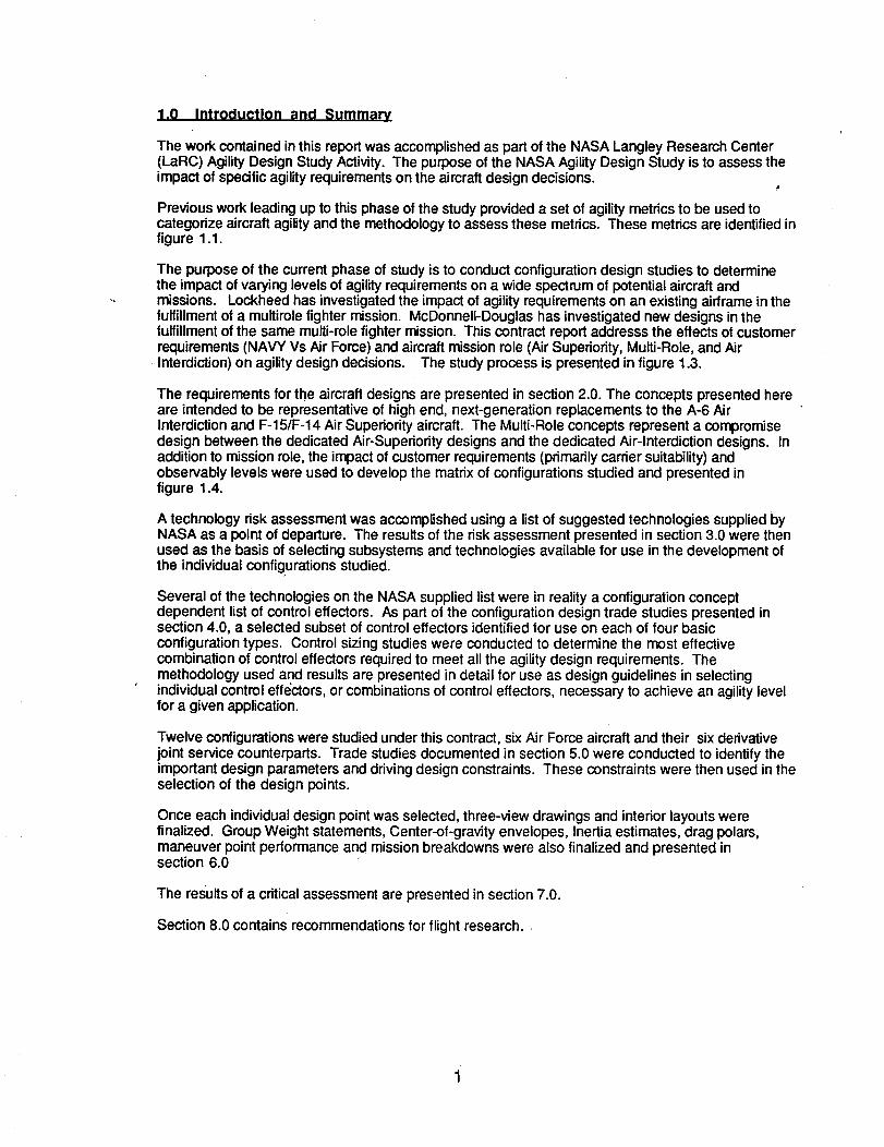
1.0 Introduction and Summary
The work contained in this report was accomplished as part of the NASA Langley Research Center(LaRC) Agility Design Study Activity. The purpose of the NASA Agility Design Study is to assess theimpact of spedfic agility requirements on the aircraft design decisions.
Previous work leading up to this phase of the study provided a set of agility metrics to be used tocategorize aircraft agilityand the methodologyto assess these metrics. These metrics are identified infigure 1.1.
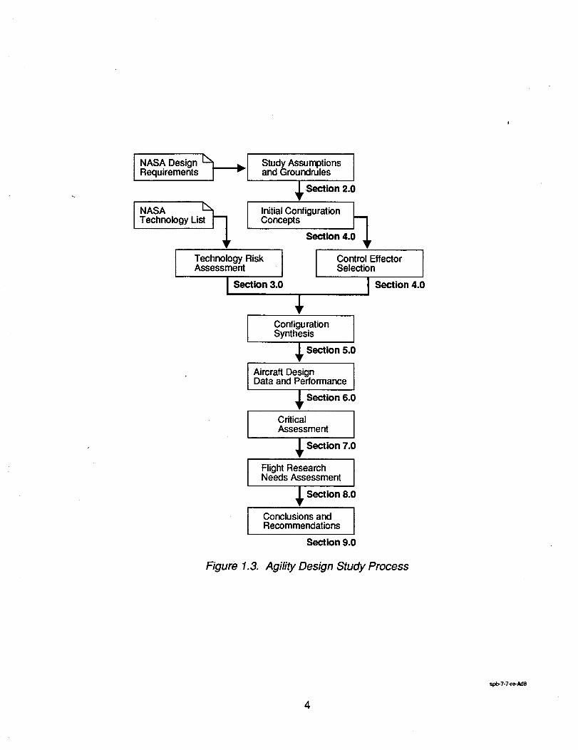
The purpose of the current phase of study is to conduct configuration design studies to determinethe impact of varying levels of agilityrequirements on a wide spectrum of potential aircraft andmissions. Lockheed has investigated the impact of agility requirements on an existing airframe in thefulfillmentof a multirolefighter mission. McDonnell-Douglas has investigated new designs inthefulfillmentof the same multi-role fighter mission. This contract report addresss the effects of customerrequirements (NAVY Vs Air Force) and aircraft mission role (Air Superiority, Multi-Role, and AirInterdiction)on agility design decisions. The study process is presented in figure 1.3.
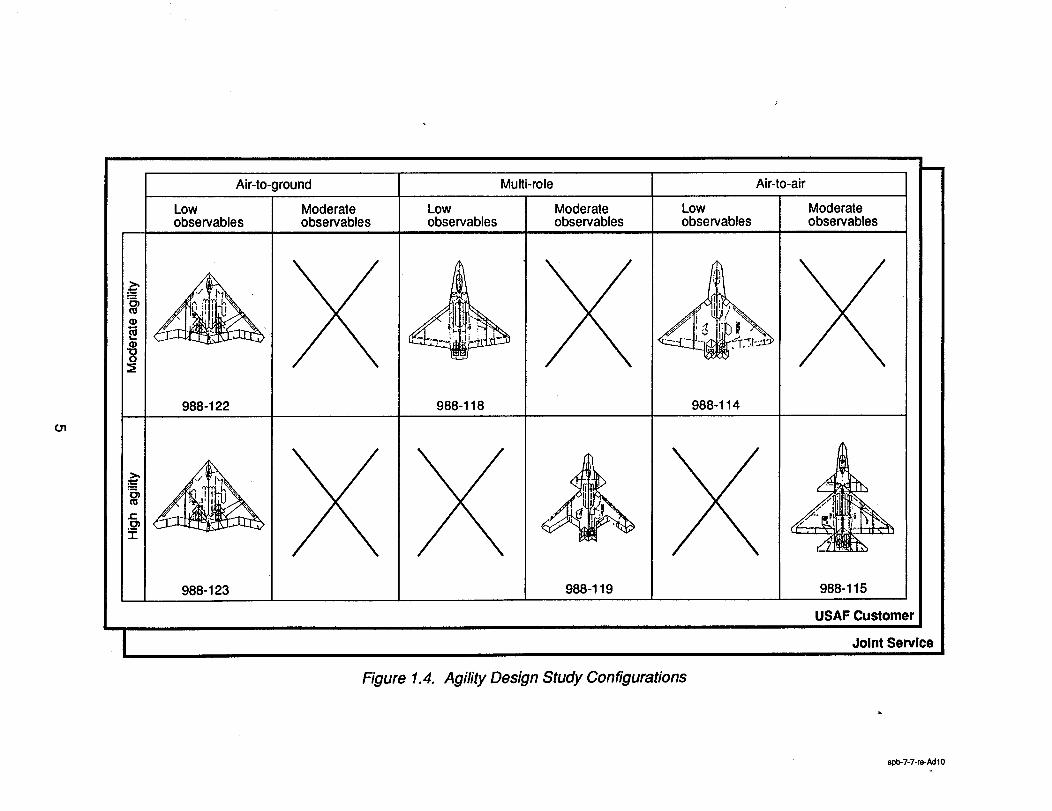
The requirements for the aircraft designs are presented in section 2.0. The concepts presented hereare intended to be representative of high end, next-generation replacements to the A-6 AirInterdictionand F-15/F-14 Air Superiority aircraft. The Multi-Role concepts represent a compromisedesign between the dedicated Air-Superiority designs and the dedicated Air-Interdiction designs. Inaddition to mission role, the impact of customer requirements (primarilycarrier suitability)andobservably levels were used to develop the matrix of configurations studied and presented infigure 1.4.
A technology risk assessment was accomplished using a list of suggested technologies supplied byNASA as a point of departure. The results of the risk assessment presented in section 3.0 were thenused as the basis of selecting subsystems and technologies available for use in the development ofthe individual configurations studied.
Several of the technologies on the NASA supplied listwere in reality a configuration conceptdependent list of control eftectors. As part of the configuration design trade studies presented insection 4.0, a selected subset of control effectors identified for use on each of four basicconfiguration types. Control sizing studies were conducted to determine the most effectivecombination of control effectors required to meet all the agility design requirements. Themethodology used and results are presented in detail for use as design guidelines in selectingindividual control effe'ctors,or combinations of control effectors, necessary to achieve an agility levelfor a given application.
Twelve configurations were studied under this contract, six Air Force aircraft and their six derivativejoint service counterparts. Trade studies documented in section 5.0 were conducted to identify theimportant design parameters and driving design constraints. These constraints were then used in theselection of the design points.
Once each individualdesign point was selected, three-view drawings and interior layouts werefinalized. Group Weight statements, Center-of-gravity envelopes, Inertia estimates, drag polars,maneuver point performance and mission breakdowns were also finalized and presented insection 6.0
The results of a criticalassessment are presented in section 7.0.
Section 8.0 contains recommendations for flight research.
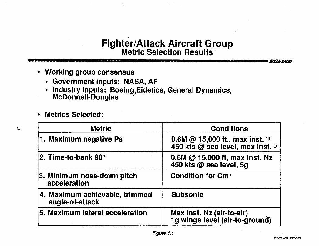
Fighter/Attack Aircraft GroupMetric Selection Results
• Working group consensus• Government inputs: NASA, AF
• Industry inputs: BoeingjEidetics, General Dynamics,McDonnell-Douglas
• Metrics Selected:
PO Metric
1. Maximum negative Ps
2. Time-to-bank 90°
3. Minimum nose-down pitchacceleration
4. Maximum achievable, trimmedangle-of-attack
5. Maximum lateral acceleration
Conditions
0.6M @ 15,000 ft., max inst.450 kts @ sea level, max inst.
0.6M @ 15,000 ft, max inst. Nz450 kts @ sea level, 5g
Condition for Cm*
Subsonic
Max inst. Nz (air-to-air)lg wings level (air-to-ground)
Figure 1.1M $299-0363 -2 01/26/94
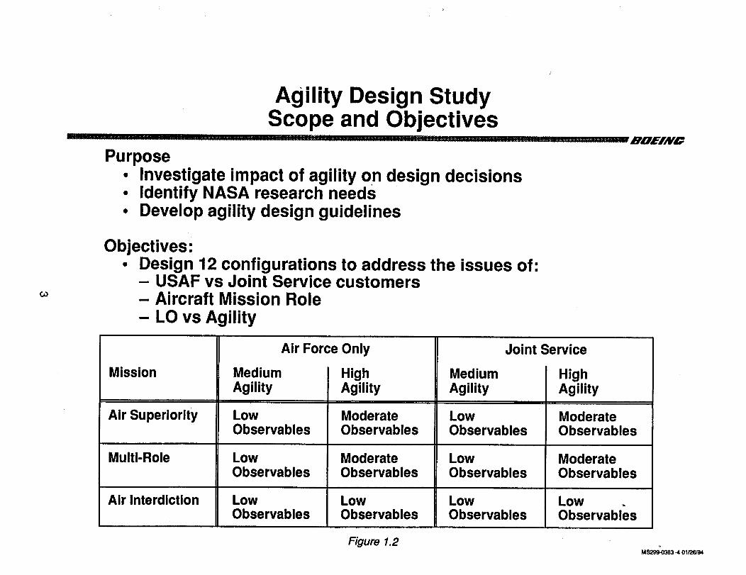
Agility Design StudyScope and Objectives
Purpose• Investigate impact of agility on design decisions• Identify NASA research needs• Develop agility design guidelines
...................... ROEIAYO
GO
Objectives:• Design 12 configurations to address the issues of:
- USAF vs Joint Service customers- Aircraft Mission Role- LO vs Agility
Mission
Air Superiority
Multi-Role
Air Interdiction
MediumAgility
Air Force Only
LowObservables
LowObservables
LowObservables
i HighAgility
ModerateObservables
ModerateObservables
LowObservables
Joint Service
MediumAgility
LowObservables
LowObservables
LowObservables
HighAgility
ModerateObservables
ModerateObservables
LowObservables
Figure 1.2M_ -401/26/94
I NASA DesignRequirements [_1
I NASA st[_
Technology Li I
Technology Risk IAssessment
I Section 3.0
Study Assumptionsand Groundrules
_, SecUon 2.0
Initial Configuration 0_._
Concepts
Section 4.
Control Effe_orSelection
I S_ion 4.0
ConfigurationSynthesis
_ Section 5.0
Aircraft DesignData and Performance
_ Section 6.0
CriticalAssessment
_ Section 7.0
Flight ResearchNeeds Assessment
_ Section 8.0
Conclusionsand IRecommendations
Section 9.0
Figure 1.3. Agility Design Study Process
spb-7-7-re-Ad8
4
01
Air-to-ground Multi-role Air-to-air
Low Moderate Low Moderate Low Moderateobservables observables observables observables observables observables
988-122
_,l_
988-123
988-118 988-114
988-119
Figure 1.4. Agility Design Study Configurations
m
988-115
USAF Customer
Joint Sen/Ice
spb-7-7-re-Adl0
2.0 Study Reauirements and Guidelines
2.1 Design Mission Profiles
Air Interdiction Mission Description
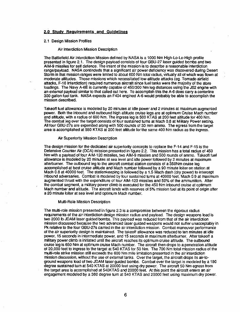
The Battlefield Air Interdiction Mission defined by NASA is a 1000 Nm High-Lo-Lo-High profilepresented in figure 2.1. The design payload consists of four GBU-27 laser guided bombs and twoAIM-9 missilesfor self defence. The intent of the mission is to describe a reasonable interdictionrange/payload. NASA contindeds that a significant air power deficiency was discovered during DesertStorm in that missionranges were limitedto about 600 Nm total radius, virtuallyall of whichwas flown atmoderate altitudes. Those missionswhich necessitated low-altitude attacks (eg. Tornado airfieldattacks, F-16 Interdiction) required numerous aircraft since fuel tanks were the majorityof the storeIoadings. The Navy A-6E is currently capable of 450/300 Nm leg distances using the J52 engine withan external payload similarto that called out here. To accomplish thisthe A-6 does carry a centerline300 gallon fuel tank. NASA expects an F404 engined A-6 would probably be able to accomplish themission described.
Takeoff fuel allowance is modeled by 20 minutes at idle power and 2 minutes at maximum augmentedpower. Both the inbound and outbound high altitude cruise legs are at optimum Cruise Mach numberand altitude, with a radius of 600 Nm. The ingress leg is 500 KTAS at 200 feet altitude for 400 Nm.The combat leg over the target consists of four sustained turns at Mach 0.8 at Military Power setting.All four GBU-27s are expended along with 500 rounds of 30 mm ammo. The egress from the targetarea is accomplished at 550 KTAS at 200 feet altitude for the same 400 Nm radius as the ingress.
Air Superiority Mission Description
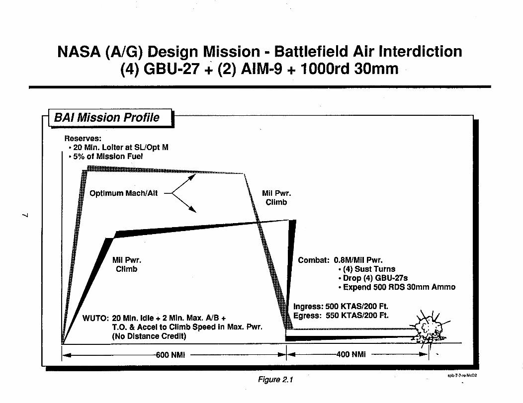
The design mission for the dedicated air superiority concepts to replace the F-14 and F-15 is theDefensive Counter Air (DCA) mission presented in figure 2.2. This mission has a total radius of 450Nm with a payload of four AIM-120 missiles, two AIM-9 missiles and 500 rounds of amino. Takeoff fuelallowance is modeled by 20 minutes at sea level and idle power followed by 2 minutes at maximumafterburner. The outbound leg to the aircraft combat station consists of a 350Nm cruise legaccomplished at best cruise altitude and Mach number followed by a 90 minute loiter on station atMach 0.8 at 40000 feet. The stationkeeping is followed by a 1.5 Mach dash (dry power) to interceptinbound adversaries. Combat is modeled by four sustained turns at 40000 feet, Mach 0.9 at maximumaugmented thrust with the expenditure of four AIM-120 missiles and 50% of the ammunition. Afterthe combat segment, a military power climb is executed for the 450 Nm inbound cruise at optimumMach number and altitude. The aircraft lands with reserves of 5% mission fuel at its point of originaftera 20 minute loiter at sea level and optimum Mach number.
Multi-Role Mission Description
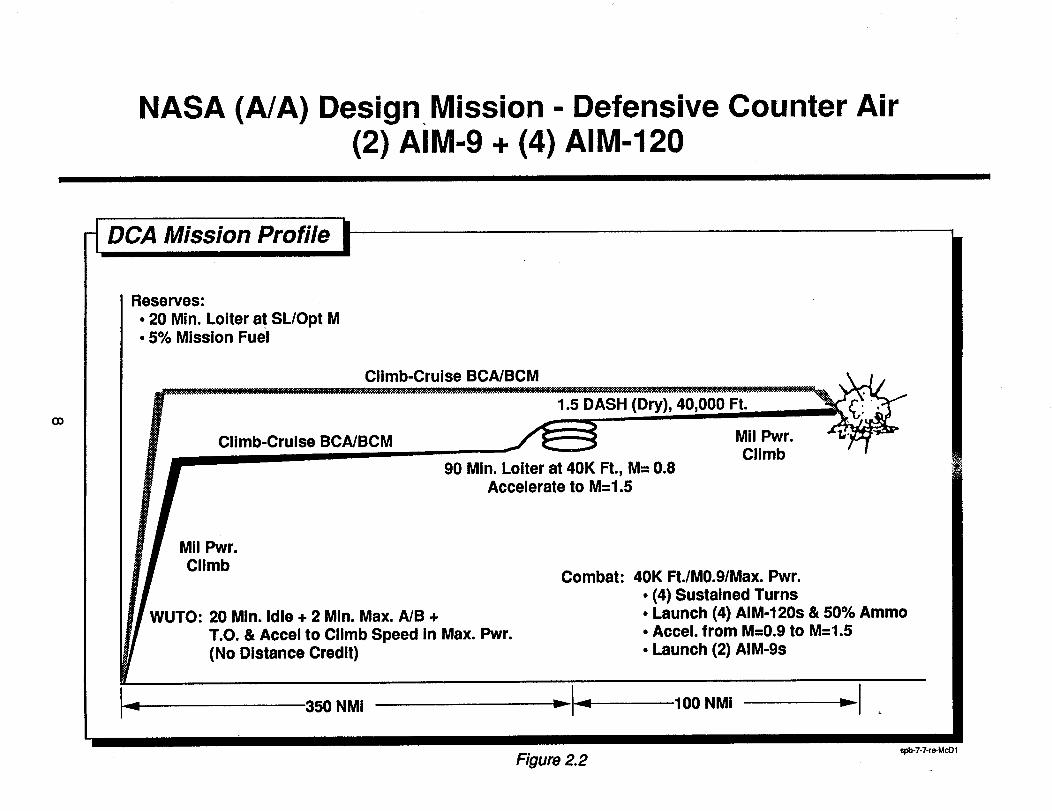
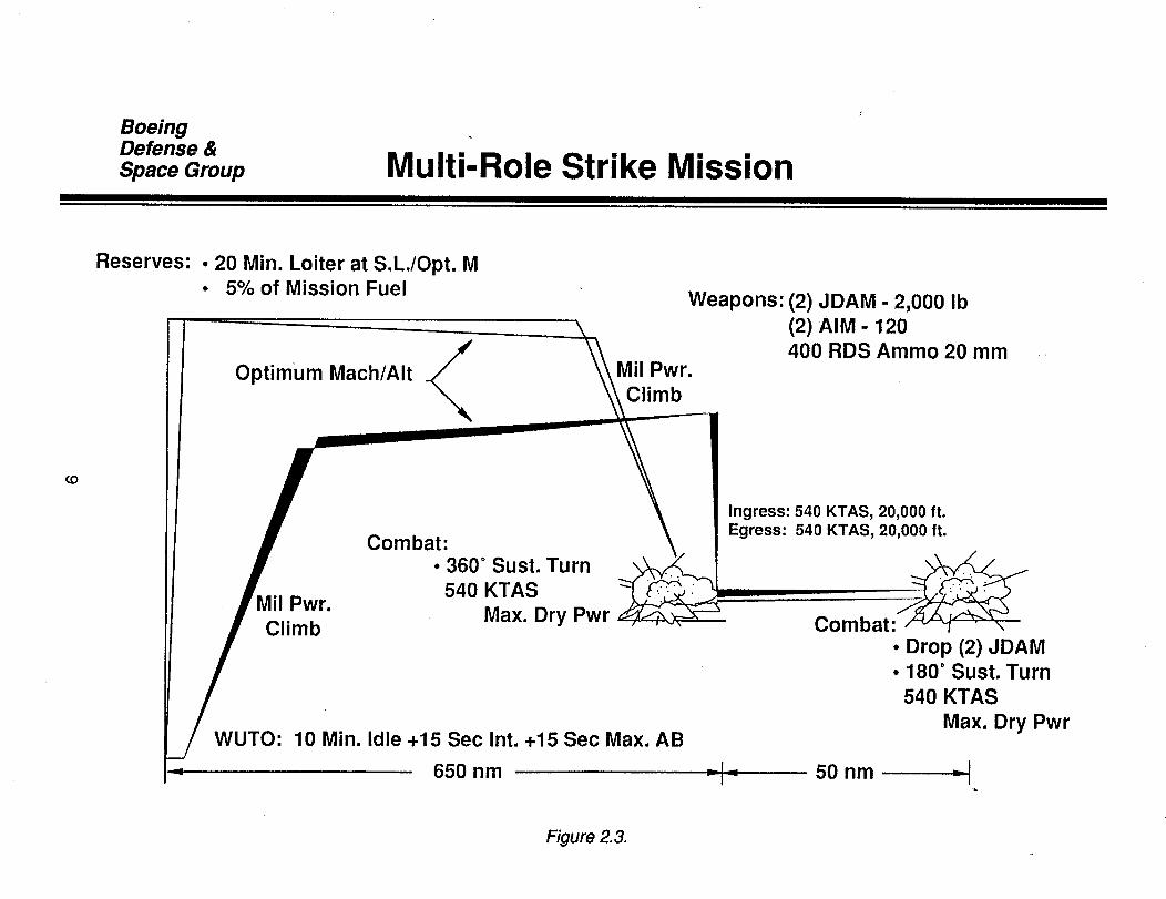
The multi-role mission presented in figure 2.3 is a compromise between the rigorous radiusrequirements of the air interdictiondesign mission radius and payload. The design weapons load istwo 2000 IbJDAM laser guided bombs. This payload was reduced from that of the air interdictionmission discussed because the two advanced laser guided weapons would not suffer unacceptably inPk relative to the four GBU-27s carded in the air interdictionmission. Combat maneuver performanceof the air superiority design is maintained. The takeoff allowance was reduced to ten minutes at idlepower, 15 seconds in intermediate power, and 15 seconds in maximum afterburner. After takeoff amilitarypower climb is initiated until the aircraft reaches its optimum cruise altitude. The outboundcruise leg is 650 Nm at optimum cruise Mach number. The aircraft then drops to a penetration altitudeof 20,000 feet to ingressto the target at 540 KTAS for 50 Nm. The 700 Nm total missionradius of themulti-role strike mission still exceeds the 600 Nm mile limitationpresented in the air interdictionmissiondiscussion, without the use of external tanks. Over the target, the aircraft drops its air-to-ground weapons load of two JDAM laser guided bombs. Combat over the target is modeled by a 180degree sustained turn at 540 KTAS at 20000 feet using dry power. The aircraft 50 Nm egress fromthe target area is accomplished at 540KTAS and 20000 feet. At this pointthe aircraft enters an airengagement modeled by a 360 degree turn at 540 KTAS and 20000 feet using maximum dry power.
6
NASA (A/G) Design Mission - Battlefield Air Interdiction(4) GBU-27 + (2) AIM-9 + 1000rd 30mm
Reserves:
• 20 ein. Loller at SL/Opt g• 5% of Mission Fuel
Optimum Mach/AIt Mil Pwr.Climb
Mil Pwr.Climb
WUTO: 20 Min. Idle + 2 Min. Max. A/B +
T.O. & Accel to Climb Speed in Max. Pwr.(No Distance Credit)
Combat: 0.8M/Mil Pwr.
• (4) Sust Turns• Drop (4) GBU-27s• Expend 500 RDS 30mm Ammo
Ingress: 500 KTAS/200 Ft.Egress: 550 KTAS/200 Ft.
600 NMi 400 NMi "-
Figure 2.1 _ spb.7-7.re-McD2
NASA (A/A) Design Mission - Defensive Counter Air(2) AIM-9. (4) AIM-120
Reserves:
• 20 Min. Loiter at SL/Opt M• 5% Mission Fuel
GO
Climb-Cruise BCA/BCM
Climb-Cruise BCA/BCM
1.5 DASH (Dry), 40,000 Ft.
Mil Pwr.Climb
90 Min. Loiter at 40K Ft., M= 0.8Accelerate to M=1.5
Mil Pwr.Climb
WUTO: 20 Min. Idle + 2 Min. Max. A/B +
T.O. & Accel to Climb Speed in Max. Pwr.
(No Distance Credit)
Combat: 40K Ft./M0.9/Max. Pwr.
• (4) Sustained Turns• Launch (4) AIM-120s & 50% Ammo• Accel. from M=0.9 to M=1.5
• Launch (2) AIM-9s
350 NMi
spb-7-7-re-McD1Figure 2.2
BoeingDefense &Space Group Multi-Role Strike Mission
Reserves: • 20 Min. Loiter at S.L./Opt. M• 5% of Mission Fuel
Optimum Mach/AIt__ Mil Pwr.Climb
Weapons: (2) JDAM - 2,000 Ib(2).AIM - 120400 RDS Ammo 20 mm
(D
Mil Pwr.Climb
Combat:• 360 ° Sust. Turn
54O KTAS
Max. Dry Pwr
WUTO: 10 Min. Idle +15 Sec Int. +15 Sec Max. AB
650 nm
Ingress: 540 KTAS, 20,000 ft.Egress: 540 KTAS, 20,000 ft.
_ .
Combat:• Drop (2) JDAM° 180 ° Sust. Turn
540 KTAS
Max. Dry Pwr
50 nm =I
Figure 2. 3.
The aircraft escapes the engagement an executes a militarypower climb to optimum cruise altitude.The aircraft then returnsto its base 650 Nm away. Reserves are specified as 20 minutes loiterat sealevel at optimum Mach number plus 5% of mission fuel.
2.2 Maneuver Performance Requirements
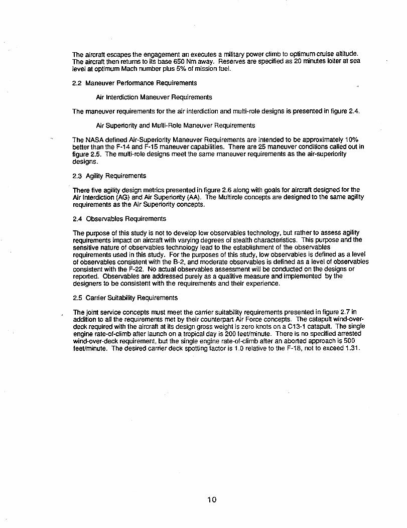
Air Interdiction Maneuver Requirements
The maneuver requirements for the air interdictionand multi-role designs is presented in figure 2.4.
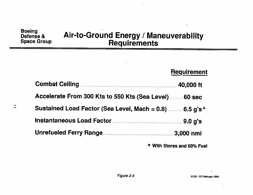
Air Superiority and Multi-Role Maneuver Requirements
The NASA defined Air-Superiority Maneuver Requirements are intended to be approximately 10%better than the F-14 and F-15 maneuver capabilities. There are 25 maneuver conditionscalled out infigure 2.5. The multi-role designs meet the same maneuver requirements as the air-superioritydesigns.
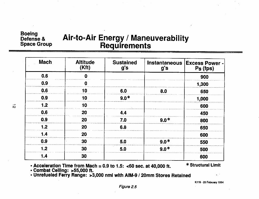
2.3 Agility Requirements
There five agilitydesign metrics presented in figure 2.6 along with goals for aircraft designed for theAir Interdiction(AG) and Air Superiority (AA). The Multirole concepts are designed to the same agilityrequirements as the Air Superiority concepts.
2.4 Observables Requirements
The purpose of this study is not to develop low observables technology, but rather to assess agilityrequirements impact on aircraft with varying degrees of stealth characteristics. This purpose and thesensitive nature of observables technology lead to the establishment of the observablesrequirements used in this study. For the purposes of this study, low observables is defined as a levelof observables consistent with the B-2, and moderate observables is defined as a level of observablesconsistent with the F-22. No actual observables assessment will be conducted on the designs orreported. Observables are addressed purely as a qualitive measure and implemented by thedesigners to be consistent with the requirements and their experience.
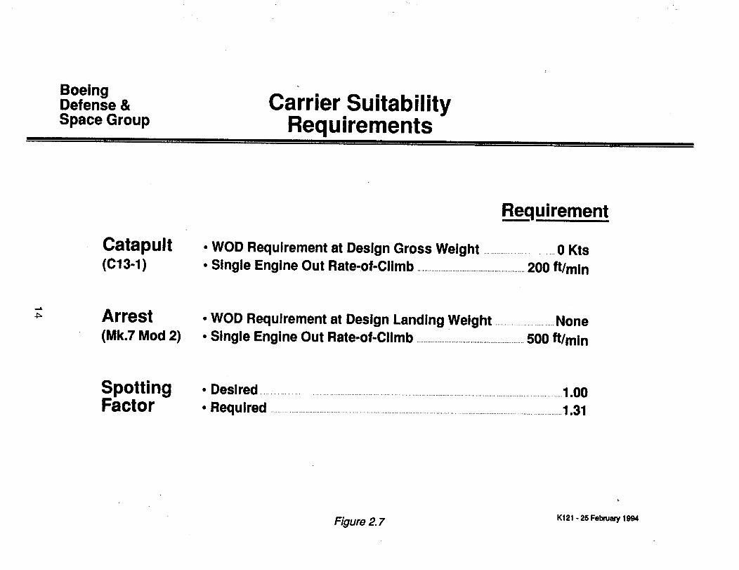
2.5 Carrier Suitability Requirements
The joint service concepts must meet the carder suitability requirements presented in figure 2.7 inaddition to all the requirements met by their counterpart Air Force concepts. The catapult wind-over-deck required with the aircraft at its design gross weight is zero knots on a C13-1 catapult. The singleengine rate-of-climb after launch on a tropical day is 200 feet/minute. There is no specified arrestedwind-over-deck requirement, but the single engine rate-of-climb after an aborted approach is 500feet/minute. The desired carder deck spotting factor is 1.0 relative to the F-18, not to exceed 1.31.
10
BoeingDefense &Space Group
Air-to-Ground Energy / ManeuverabilityRequirements
..¢
Requirement
Combat Ceiling ...............................................................................................................................................................40,000 ft
Accelerate From 300 Kts to 550 Kts (Sea Level) .....................60 sec
Sustained Load Factor (Sea Level, Mach = 0.8) ........................6.5 g's*
Instantaneous Load Factor .....................................................................................................................9.0 g's
Unrefueled Ferry Range .....................................................................................................................3,000 nmi
'_ With Stores and 60% Fuel
Figure 2.4 K120 - 25 February 1994
BoeingDefense &Space Group
Air-to-Air Energy / ManeuverabilityRequ=rements
PO
Mach Altitude Sustained Instantaneous Excess Power-(Kft) g's g's Ps (fps)
0.6 0 900......................... ....................................... I ............................................................. t ............................................................... I................................................................ I...............................................................
0.9 0 1,300
0.6 10 6.0 8.0 650................................................................ I ............................................................... f ............................................................... I.................................... : ........................... I ................................................................
..........................o.9.......................................................,Io...................................................., g.O,......................................................................................................................................................., , 1,ooo1.2 10 600
............................................................... I ................................................................ I ............................................ .................... I ............................................................... ! ...............................................................
0.6 20 4.4 450............................................................... I ............................................................... I ............................................................... I ............................................................... l ...............................................................
0.g 20 7.0 g.0 * 800................................................................ i ............................................................... f, ............................................................................................................................... i ................................................................
1.2 20 6.8 650
1.4 20 600............................................................... I ................................................................ I ................................................................ I ............................................................... 4 ................................................................
0.g 30 5.0 9.0" 550................................................................ I ............................................................... t ............................................................... I ................................................................ I ...............................................................
1.2 30 5.0 9.0 _' 500................................................................ I ....................................... :....................... t ............................................................... I ................................................................ I ...............................................................
1.4 30 600
• Acceleration Time from Mach = 0.9 to 1.5:<60 sec. at 40,000 ft. ,_Structural Limit• Combat Ceiling: >55,000 ft.• Unrefueled Ferry Range: >3,000 nmi with AIM-9 / 20mm Stores Retained
Kl19 - 25 February 1994
Figure 2.5
BoeingDefense &
Space Group
Fighter / Attack Aircraft GroupAgility Design Goals
Co
Metric
1. MaximumNegative Ps
A-A:
Conditions
Mach = 0.6, 15 Kft (Nz = 5.5g)
Low
-800ft/sec
Medium
-450ft/sec
2. Time-to-Bankand Capture 90 °
3. MinimumNose-DownPitchAcceleration
4. MaximumAchievableDeparture-FreeAngle-of-Attack
. MaximumLateralAcceleration
A-G: 450 Kts Sea Level (Nz = 7.5g)
A-A: Mach = 0.6, 15 Kft,Maximum Instantaneous Nz = 9.0
A-G: 450 Kts Sea Level, 5g
A-A: Condition for Cm*Use Mach = 0.6, 15 Kftfor Consistency
A-G: Same
With Air-to-Air Stores, Subsonic
A-A: Mach = 0.6, 15 Kft,Maximum Instantaneous Nz = 9.0
A-G: 450 Kts Sea Level, Wings Level
(Same)
3.0 sec
2.0 sec
-0.05rad/sec2
(Same)
25 deg
0.25 g
0.6 g
(Same)
2.5 sec
1.5 sec
-0.15rad/sec2
(Same)
40 deg
0.4 g
1.2 g
High
-100ft/sec
(Same)
1.5 sec
1.0 sec
-0.35rad/sec2
(Same)
70 deg
1.0 g
2.0 g
Figure 2. 6
spb-8-7-re-Ad6
BoeingDefense &Space Group
Ca rrier .Su ita b iIityRequirements
Catapult(c13-1)
Requirement
• WOD Requirement at Design Gross Weight ........................................0 Kts• Single Engine Out Rate-of-Climb .............................................................200 ft/min
Arrest(Mk.7 Mod 2)
• WOD Requirement at Design Landing Weight .................................None• Single Engine Out Rate-of-Climb .............................................................500 ft/min
SpottingFactor
• Desired ............................................................................................................................................................................1.00• Required ......................................................................................................................................................................1.31
Figure 2. 7 K121 o 25 February 1994
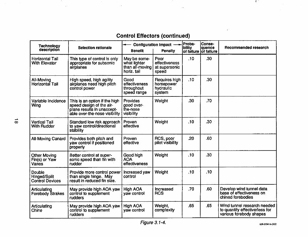
3.0 Technoloav Risk Assessment
The objective of the technology assessment task was to identifythe technologies that provide thegreatest benefit for the twelve candidate Agility Design Study (ADS) concepts and also to help NASAidentify meaningful research needs which, if accomplished, will improve future aircraft design,manufacturing and performance. '
3.1 Technology Risk Assessment Approach
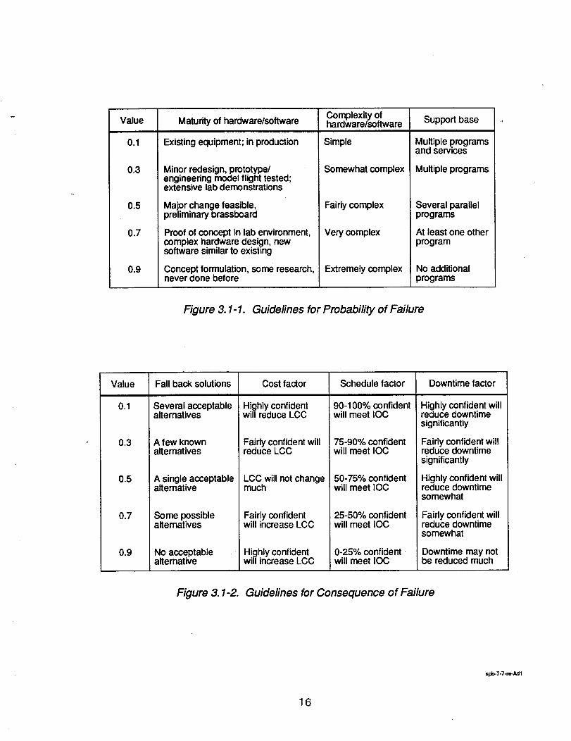
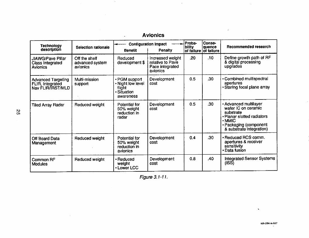
A "technology matrix"was developed by the Boeing Military Airplanes (BMA) technology staff usingthe technology list provided by NASA with additions and combinations as deemed necessary to bestidentify the technologies that might be configuration drivers or, required to satisfy the ADS missionperformance criteria. The basic ground rules used by the technical assessment experts were that theIOC date would be 2005 and development testing (materials, systems, aerodynamics, etc.) would beaccomplished. The technology assessors were also required to:
(1) Provide a brief description of the individual technology.(2) Provide a rationale for determining whether the technology should or should not be
selected for incorporation into ADS configurations.(3) Provide the expected impact, either beneficial or detrimental, the technology would have
on the configurations if incorporated into the design.(4) Provide a subjective assessment of the probability and consequence of failure as
determined by the ground rules shown in Tables 3.1-- 1 and 3.1-2 and described inSection 3.1.1.
(5) Provide a suggestion of research needed to bring the technology to maturity andvalidation.
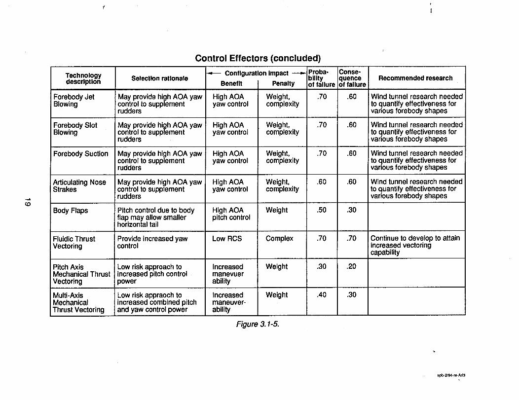
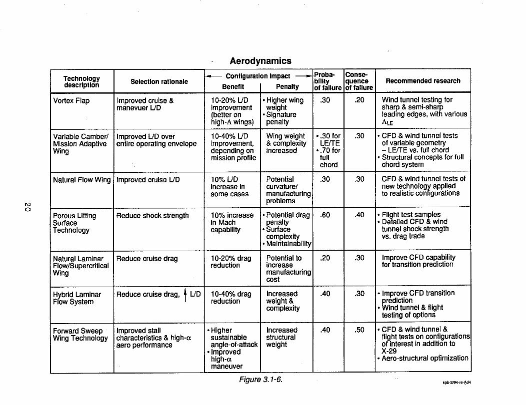
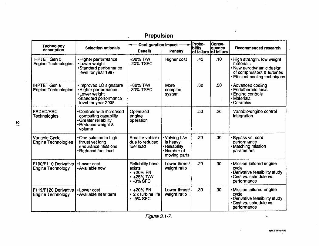
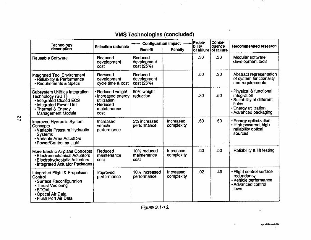
The resulting "technology matrix" is shown in figure 33.1-3through figure 3.1-16.
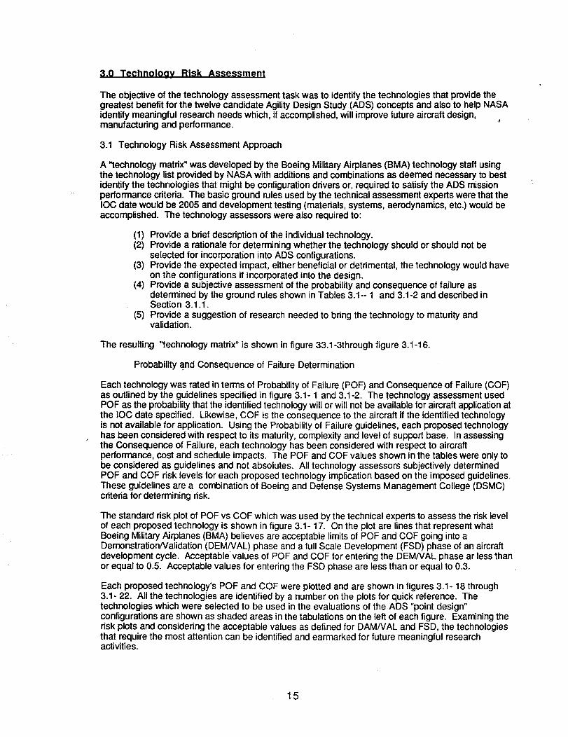
Probability and Consequence of Failure Determination
Each technology was rated in terms of Probability of Failure (POF) and Consequence of Failure (COF)as outlined by the guidelines specified in figure 3.1- 1 and 3.1-2. The technology assessment usedPOF as the probability that the identified technology will or will not be available for aircraft application atthe IOC date specified. Likewise, COF is the consequence to the aircraft if the identified technologyis not available for application. Using the Probability of Failure guidelines, each proposed technologyhas been considered with respect to its maturity, complexity and level of support base. In assessingthe Consequence of Failure, each technology has been considered with respect to aircraftperformance, cost and schedule impacts. The POF and COF values shown in the tables were only tobe considered as guidelines and not absolutes. All technology assessors subjectively determinedPOF and COF risk levels for each proposed technology implication based on the imposed guidelines.These guidelines are a combination of Boeing and Defense Systems Management College (DSMC)criteda for determining risk.
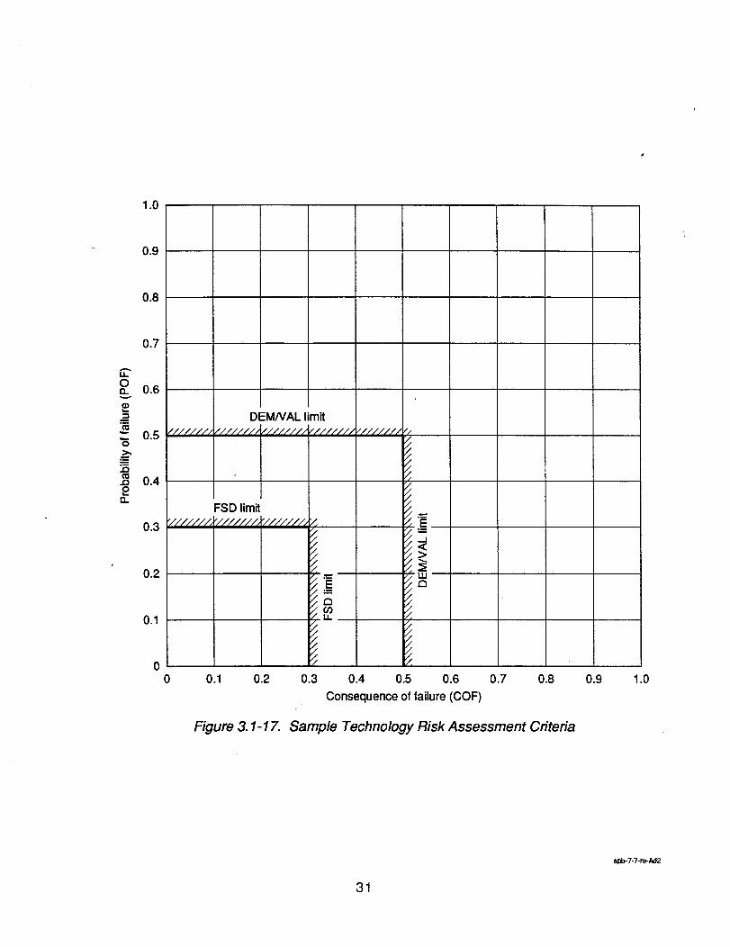
The standard risk plot of POF vs COF which was used by the technical experts to assess the risk levelof each proposed technology is shown in figure 3.1- 17. On the plot are lines that represent whatBoeing Military Airplanes (BMA) believes are acceptable limits of POF and COF going into aDemonstration/Validation (DEM/VAL) phase and a full Scale Development (FSD) phase of an aircraftdevelopment cycle. Acceptable values of POF and COF for entering the DEM/VAL phase ar less thanor equal to 0.5. Acceptable values for entering the FSD phase are less than or equal to 0.3.
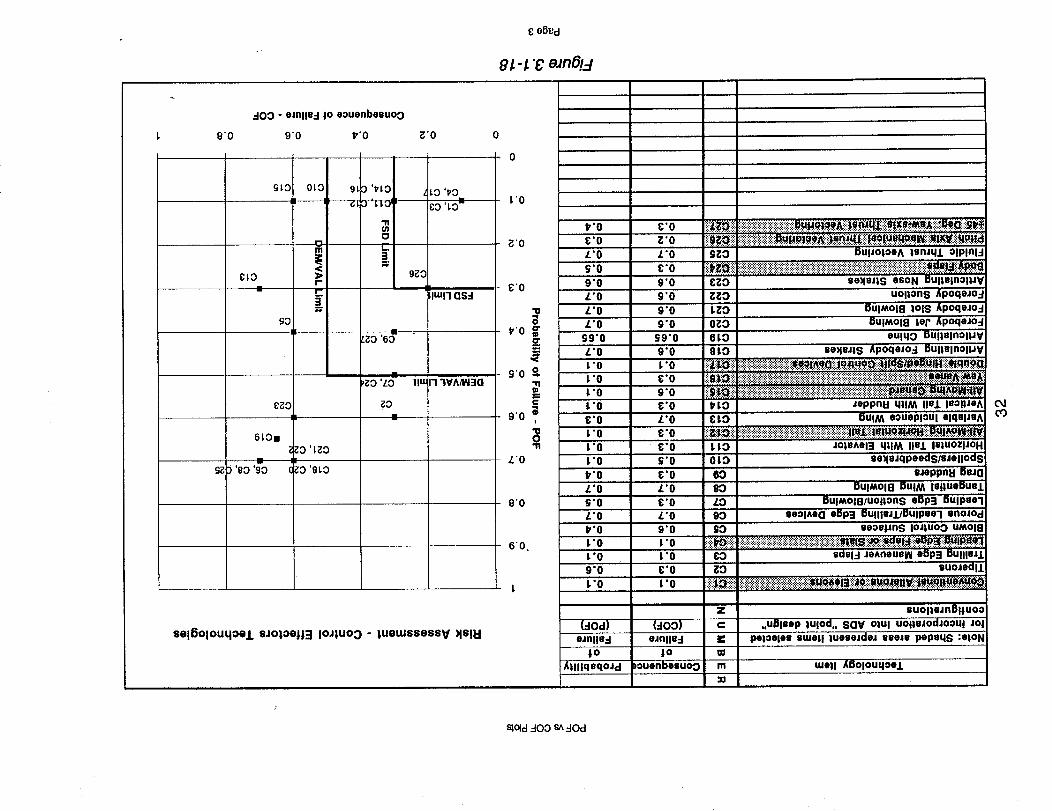
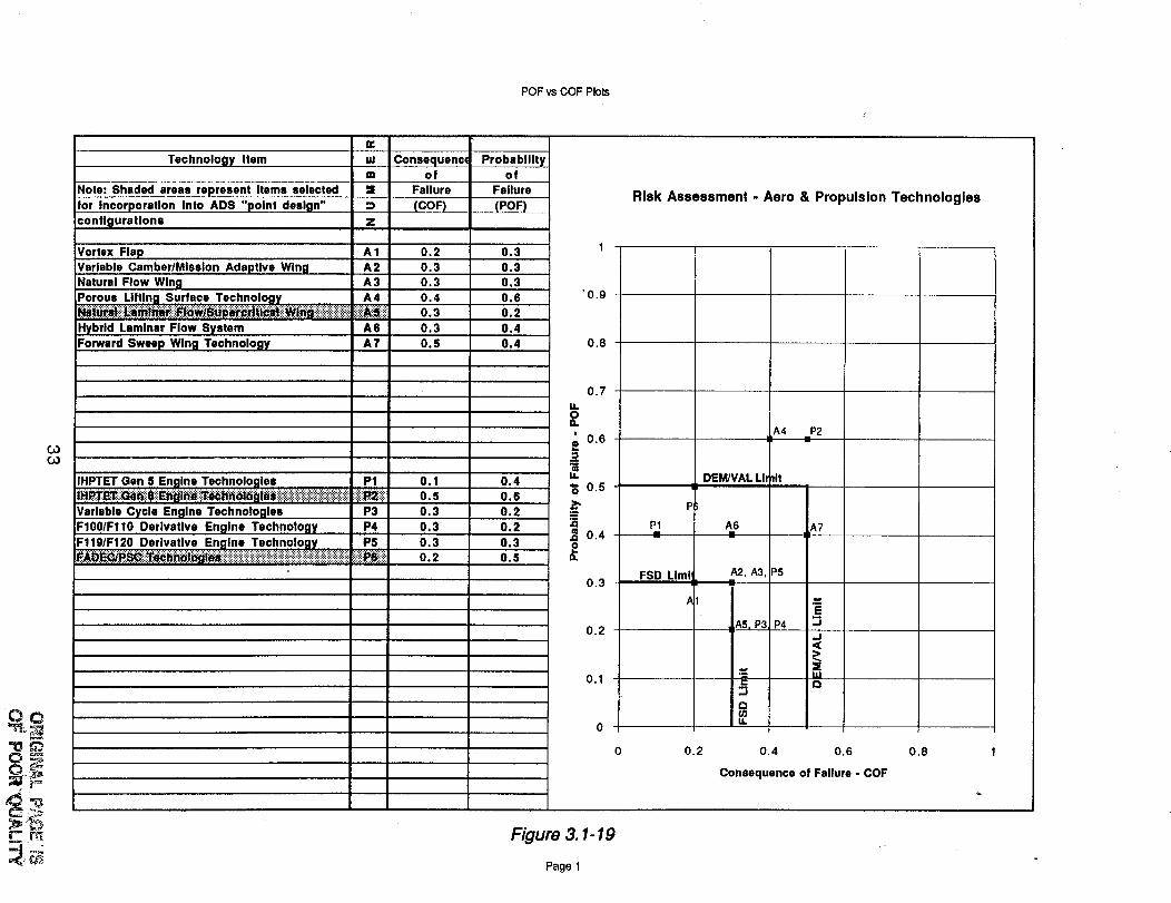
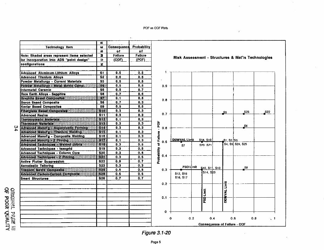
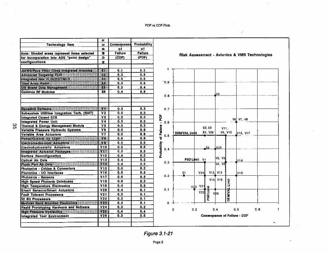
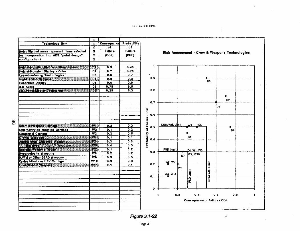
Each proposed technology's POF and COF were plotted and are shown in figures 3.1- 18 through3.1- 22. All the technologies are identified by a number on the plots for quick reference. Thetechnologies which were selected to be used in the evaluations of the ADS "point design"configurations are shown as shaded areas in the tabulations on the left of each figure. Examining therisk plots and considering the acceptable values as defined for DAM/VAL and FSD, the technologiesthat require the most attention can be identified and earmarked for future meaningful researchactivities.
15
Complexity of Support baseValue Maturity of hardware/software hardware/software
0.1 Existing equipment; in production
0.3
0.5
0.7
0.9
Minor redesign, prototype/engineering model flight tested;extensive lab demonstrations
Major change feasible,preliminary brassboard
Proof of concept in lab environment,complex hardware design, newsoftware similar to existing
Concept formulation, some research,never done before
Simple
Somewhat complex
Fairly complex
Very complex
Extremely complex
Multiple programsand services
Multiple programs
Several parallelprograms
At least one otherprogram
No additionalprograms
Figure 3.1-1. Guidelines for Probability of Failure
Value
0.1
0.3
0.5
0.7
0.9
Fall back solutions
Several acceptableaitematives
A few knownalternatives
A single acceptablealternative
Some possiblealternatives
No acceptablealternative
Cost factor
Highly confidentwill reduce LCC
Fairly confident willreduce LCC
LCC will not changemuch
Fairly confidentwill increase LCC
Highly confidentwill increase LCC
Schedule factor
90-100% confidentwill meet IOC
75-90% confidentwill meet IOC
50-75% confidentwill meet IOC
25-50% confidentwill meet IOC
0-25% confidentwill meet IOC
Downtime factor
Highly confident willreduce downtimesignificantly
Fairly confident willreduce downtimesignificantly
Highly confident willreduce downtimesomewhat
Fairly confident willreduce downtimesomewhat
Downtime may notbe reduced much
Figure 3.1-2. Guidefines for Consequence of Failure
spb-7-7-re-Ad 1
16
¢
Control Effectors
Technologydescription
ConventionalAilerons
Tiperons
Trailing EdgeManeuver Flaps
Leading EdgeFlaps or Slats
Blown ControlDevices...,t.
,,,j
Porous Leading/Trailing EdgeDevices
Leading EdgeSuction/Blowing
TangentialWing Blowing
Drag rudders
Spoilers/Speedbrakes
Selection rationale
Roll performance at highAOA better than spoilers
Proven
Increased high liftcapability
Use to reduce controlsurf size or to increasecontrol power
May provide increased highlift with low RCS & reducedcomplexity compared toslats/slotted flaps
Increased high lift
Provides high lift with lesscomplexity
Provide yaw control withno vertical fins
Wing spoilers very effectiveahead of high lift flaps
Configuration Impact
Benefit I
Effective tohigh AOA
Increasedmaneuver-ability
Low takeoff& approachspeeds
Significantincrease ineffectiveness
Low RCS,reducedmechanicalcomplexity
Lower T.O.& appr. speed
Simplersystem thanslot blowing
Low RCS
Low AOAeffectiveness
F/gure
Penalty
Heavy attackpivot req'd.
Weight
Increased IUTandcomplexity
Ineffective athigh speed
Unprovenconcept
Complexity
Ineffective athigh speed
Reducedeffectiveness
Weight, poorhigh AOAeffectiveness
_.1-3.
Proba-bilityof failure
.10
.60
.01
.10
.40
.70
.50
.70
.40
.10
Consmquenceoffallure
.I0
.30
.01
.I0
.6O
.7O
.30
.7O
.3O
.5O
Recommended research
Wind tunnel test databaseneeded to quantify benefits
Wind tunnel databaseneeded for flexible controlconcepts
Share LE slateffectiveness
More wind tunnel test dataneeded to prove concept
More wind tunnel test dataneeded to prove concept
Wind tunnel test databaseneeded to quantify benefitsvs. blowing requirements
Wind tunnel databaseneeded as a function ofdeflection and wing planform
spb-2/g4-re-Ad 1
Control Effectors (continued)
-.J.
CO
Technologydescription
Horizontal TailWith Elevator
All-MovingHorizontal Tail
Variable IncidenceWing
Vertical TailWith Rudder
All-Moving Canard
Other MovingFin(s) or YawVanes
DoubleHinged/SplitControl Devices
ArticulatingForebody Strakes
ArticulatingChine
Selection rationale
This type of control is onlyappropriate for subsonica_rplanes
High speed, high agilityairplanes need high pitchcontrol power
This is an option if the highspeed design of the air-plane results in unaccept-able over-the-nose visibility
Standard low risk approachto yaw control/directionalstability
Provides both pitch andyaw control if positionedproperly
Better control at super-sonic speed than fin withrudder
Provide more control powerthan single hinge. Mayresult in reduced fin size.
May provide high AOA yawcontrol to supplementrudders
May provide high AOA yawcontrol to supplementrudders
Configuration Impact --_
Benefit
May be some-what lighterthan all-movinghoriz, tail
Goodeffectivenessthroughoutspeed range
Providesgood over-the-nosevisibility
Proveneffective
Proveneffective
Good highAOAeffectiveness
Increased yawcontrol
High AOAyaw control
High AOAyaw control
Penalty
Pooreffectivenessat supersonicspeed
Requires highhorsepowerhydraulicsystem
Weight
Weight
RCS, poorpilot visibility
Weight
Weight
IncreasedRCS
Weight,complexity
Proba-bilityof failure
.10
.10
.30
.10
.20
.10
.10
.70
.65
Conse-quenceof failure
.30
.30
.70
.30 •
.60
.30
.10
.60
.65
Recommended research
Develop wind tunnel database of effectiveness onchined forebodies
Wind tunnel research neededto quantify effectiver_ess forvarious forebody shapes
Figure 3.1-4. spb-2/94-re.P, d2
Control Effectors (concluded)
.-¢
_O
Technologydescription
Forebody JetBlowing
Forebody SlotBlowing
Forebody Suction
Articulating NoseStrakes
Body Flaps
Fluidic ThrustVectoring
Pitch AxisMechanical ThrustVectoring
Multi-AxisMechanicalThrust Vectoring
Selection rationale
May provide high AOA yawcontrol to supplementrudders
May provide high AOA yawcontrol to supplementrudders
May provide high AOA yawcontrol to supplementrudders
May provide high AOA yawcontrol to supplementrudders
Pitch control due to bodyflap may allow smallerhorizontal tail
Provide increased yawcontrol
Low risk approach toincreased pitch controlpower
Low risk appraoch toincreased combined pitchand yaw control power
Configuration Impact
Benefit
High AOAyaw control
High AOAyaw control
Hig h AOAyaw control
High AOAyaw control
High AOApitch control
Low RCS
Increasedmanevuerability
Increasedmaneuver-ability
I Penalty
Weight,complexity
Weight,complexity
Weight,complexity
Weight,complexity
Weight
Complex
Weight
Weight
Proba-bility;of failure
.70
.70
.70
.60
.50
.70
.30
.40
Conse-quenceof failure
.60
.60
.60
.60
.30
.70
.20
.30
Recommended research
Wind tunnel research neededto quantify effectiveness forvarious forebody shapes
Wind tunnel research neededto quantify effectiveness forvarious forebody shapes
Wind tunnel research needed
to quantify effectiveness forvarious forebody shapes
Wind tunnel research neededto quantify effectiveness forvarious forebody shapes
Continue to develop to attainincreased vectoringcapability
Figure 3.1-5.
$pb-2/g4-re-Ad3
Aerodynamics
POC_
Technologydescription
Vortex Flap
Variable Camber/Mission AdaptiveWing
Natural Flow Wing
Porous LiftingSurfaceTechnology
Natural LaminarFlow/SupercriticalWing
Hybrid LaminarFlow System
Forward SweepWing Technology
Selection rationale
Improved cruise &manevuer IJD
Improved L/D overentire operating envelope
Improved cruise L/D
Reduce shock strength
Reduce cruise drag
Reduce cruise drag, t L/D
Improved stallcharacteristics & high-c_aero performance
Configuration Impact
Benefit I Penalty
10-20% L/Dimprovement(better onhigh-A wings)
10-40% L/Dimprovement,depending onmission profile
10% L/Dincrease insome cases
10% increasein Machcapability
10-20% dragreduction
10-40% dragreduction
• Highersustainableangle-of-attack
• Improvedhigh-e¢maneuver
• Higher wingweight
• Signaturepenalty
Wing weight& complexityincreased
Potentialcurvature/manufacturingproblems
• Potential drag
• penaltySurfacecomplexity
• Maintainability
Potential toincreasemanufacturingcost
Increasedweight &complexity
Increasedstructuralweight
Proba-bilityof faUure
.3O
• .30 forLE/TE
• .70 forfullchord
.30
.60
.2O
.40
.4O
Conse-quenceof fallure
.20
.30
.30
.40
.3O
.3O
.50
Recommended research
Wind tunnel testing forsha.rp & semi-sharpleading edges, with variousALE
• CFD & wind tunnel testsof variable geometry- LE/TE vs. full chord
• Structural concepts for fullchord system
CFD & wind tunnel tests ofnew technology appliedto realistic configurations
Flight test samplesDetailed CFD & wind
tunnel shock strengthvs. drag trade
Improve CFD capabilityfor transition prediction
Improve CFD transition
i predictionWind tunnel & flighttesting of options
• CFD & wind tunnel &flight tests on configurationsof interest in addition toX-29
• Aero-structural optimization
Figure 3.1-6. spb-2/94-re-Ad4
b
Propulsion
Po
Technologydescrlptlon
IHPTET Gen 5Engine Technologies
IHPTET Gen 6Engine Technologies
FADEC/PSCTechnologies
Variable CycleEngine Technologies
F100/F110 DerivativeEngine Technology
F119/F120 DerivativeEngine Technology
Selection ratlonale
• Higher performance• Lower weight• Standard performancelevel for year 1997
• Improved LO signature• Higher performance• Lower weight• Standard performancelevel for year 2008
•Controls with increasedcomputing capability
•Greater reliability• Reduced weight &volume
• One solution to highthrust yet longendurance missions
• Reduced fuel load
• Lower cost• Available now
• Lower cost• Available near term
Configuration Impact
Benefit
+30% T/W-20% TSFC
+60% T/W-30% TSFC
Optimizedengineoperation
Smaller vehicledue to reducedfuel load
Reliability baseexists• +20% FN• +25% T/W• -3% SFC
• +20% FN• 2 x turbine life• -5% SFC
I Penalty
Higher cost
Morecomplexsystem
•Valving h/wis heavy
• Reliability• Number ofmoving parts
Lower thrust/weight ratio
Lower thrust/weight ratio
Proba-bilityof failure
.4O
.60
.50
.20
.20
.30
Conse-quenceof fallure
.I0
.50
.20
.30
.30
.30
Recommended research
• High strength, low weightmaterials
• New aerodynamic designof compressors & turbines
• Efficient cooling techniques
• Advanced cooling• Endothermic fuels• Engine controls• Materials• Ceramics
Variable/engine controlintegration
• Bypass vs. coreperformance
• Matching missionparameters
• Mission tailored enginecycle
• Derivative feasibility study• Cost vs. schedule vs.performance
• Mission tailored enginecycle
• Derivative feasibility study• Cost vs. schedule vs.
performance
Figure 3.1-7.
spb-2/9,4-m-Ad5
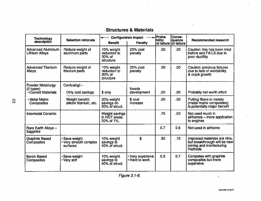
.Structures & Materials
PO
Technologydescription
Advanced Aluminum-Lithium Alloys
Advanced TitaniumAlloys
Powder Metallurgy
(2 types)Current Materials
• Metal MatrixComposites
Intermetal Ceramic
Rare Earth Alloys -Sapphire
Graphite BasedComposites
Boron BasedComposites
Selection ratlonale
Reduce weight ofaluminum parts
Reduce weight oftitanium parts
Confusingl -
Only cost savings
Weight benefit:silicon titanium, etc.
• Save weight• Very smooth complex
surfaces
• Save weight• Very stiff
Configuration Impact
Benefit Penalty
10% weightreduction to30% ofstructure
10% weightreduction to30% ofstructure
$ only
30% weightsavings on50% of struct.
Weight savingsin HOT areas.20% of 1%.
10% weightsavings to40% of struct.
10% weightsavings to40% of struct.
20% costpenalty
20% costpenalty
Needsdevelopment
$ costincrease
$
• Very expensive• Hard to work
Proba-bllityof failure
.50
.50
.50
.50
.70
0.7
.50
0.3
Conse-quence!of fallure
.50
.50
.50
.50
.50
0.6
.10
0.7
Recommended research
Caution: this has been triedbefore and FAILS due topoor ductility
Caution: previous failuresdue to lack of weldability& crack growth
Probably not worth effort
Putting fibers in metalsmetal matrix composites)s potentially major benefit
Not used much inairframes - more applicationto engines
Not used in airframe
Improved materials are nice,but breakthrough will be newjoining and manfacturingmethods
Competes with graphitecomposites but moreexpensive
Figure 3.1-8.
spb-2/94-re-A¢110
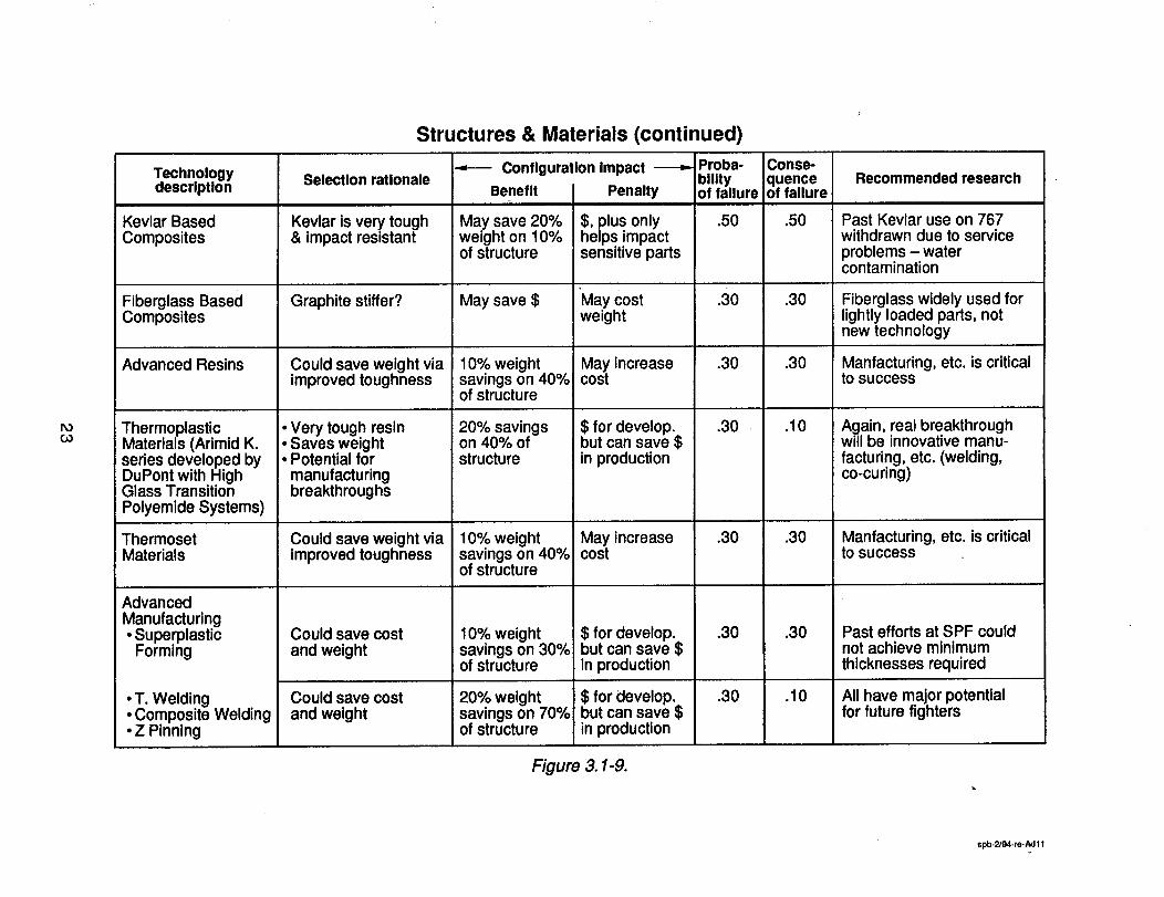
Structures & Materials (continued)
POGO
Technologydescription
Kevlar BasedComposites
Fiberglass BasedComposites
Advanced Resins
ThermoplasticMaterials (Arimid K.series developed byDuPont with HighGlass TransitionPolyemide Systems)
ThermosetMaterials
AdvancedManufacturing• Superplastic
Forming
T. WeldingComposite Welding
• Z Pinning
Selection rationale
Kevlar is very tough& impact resistant
Graphite stiffer?
Could save weight viaimproved toughness
• Very tough resin• Saves weight• Potential formanufacturingbreakthroughs
Could save weight viaimproved toughness
Could save costand weight
Could save costand weight
Configuration Impact
Benefit
May save 20%weight on 10%of structure
May save $
10% weightsavings on 40%of structure
20% savingson 40% ofstructure
10% weightsavings on 40%of structure
10% weightsavings on 30%of structure
20% weightsavings on 70%of structure
I Penalty
$, plus onlyhelps impactsensitive parts
May costweight
May increasecost
$ for develop.but can save $in production
May increasecost
$ for develop.but can save $in production
$ for develop.but can save $in production
Proba-bilityof failure
.50
.30
.30
.30 •
.30
.30
.30
Cons_quenceoffallure
.50
.30
.30
.I0
.30
.30
.I0
Recommended research
Past Kevlar use on 767withdrawn due to serviceproblems - watercontamination
Fiberglass widely used forlightly loaded parts, notnew technology
Manfacturing, etc. is criticalto success
Again, real breakthroughwill be innovative manu-facturing, etc. (welding,co-curing)
Manfacturing, etc. is criticalto success
Past efforts at SPF couldnot achieve minimumthicknesses required
All have major potentialfor future fighters
Figure 3.1-9.
spb-2/94.re.Ad11
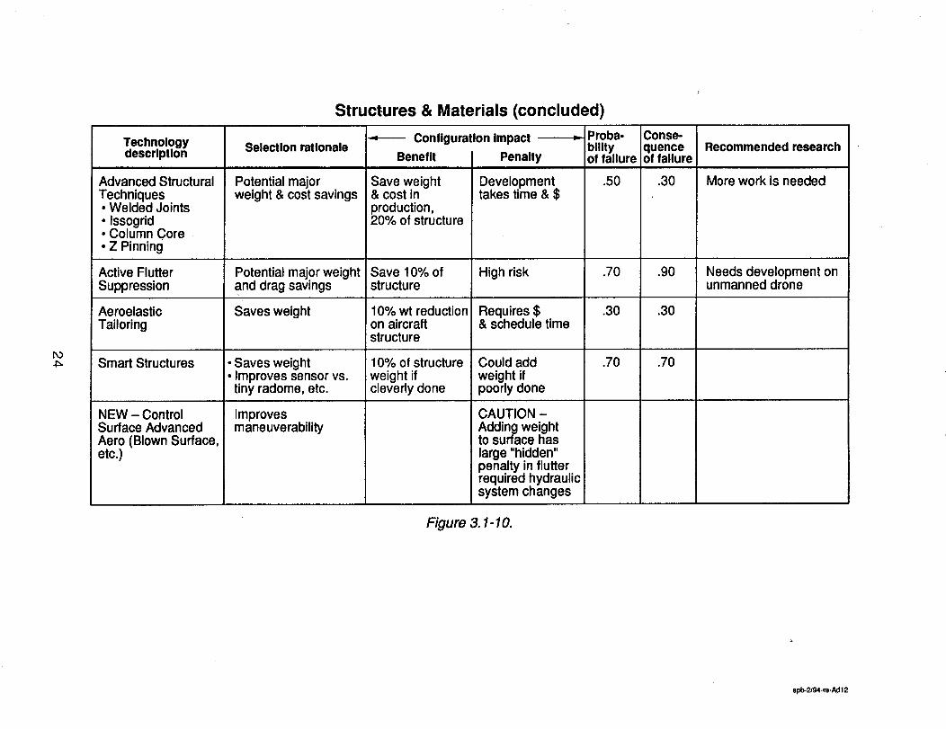
Structures & Materials (concluded)
Po
Technologydescription
Advanced StructuralTechniques• Welded Joints• Issogrid• Column Core• Z Pinning
Active FlutterSuppression
Selection rationale
Potential majorweight & cost savings
AeroelasticTailoring
Smart Structures
NEW - ControlSurface AdvancedAero (Blown Surface,etc.)
Potential major weightand drag savings
Saves weight
• Saves weight• Improves sensor vs.
tiny radome, etc.
Improvesmaneuverability
Benefit
Configuration Impact
Penalty
Save weight& cost inproduction,20% of structure
Save 10% ofstructure
10% wt reductionon aircraftstructure
10% of structureweight ifcleverly done
Developmenttakes time & $
High risk
Requires $& schedule time
Could addweight ifpoorly done
CAUTION -Adding weightto surface haslarge "hidden"penalty in flutterrequired hydraulicsystem changes
Proba-bilityof failure
.50
.70
.30
.70
Cons_quenceoffallure
.30
.90
.30
.70
Recommended research
More work is needed
Needs development onunmanned drone
Figure 3.1-10.
spb.2/94-re-/_ 12
¢
Avionics
O1
Configuration Impact
Benefit I Penalty
Increased weightrelative to PavePace integratedavionics
Technologydescription
JIAWG/Pave PillarClass IntegratedAvionics
Advanced TargetingFLIR, IntegratedNav FLIR/IRST/MLD
Tiled Array Radar
Off Board DataManagement
Common RFModules
Selection rationale
Off the shelfadvanced systemavionics
Multi-missionsupport
Reduced weight
Reduced weight
Reduced weight
Reduceddevelopment $
• PGM support• Night low levelflight
• Situationawareness
Potential for50% weightreduction inradar
Potential for50% weightreduction inavionics
• Reducedweight
• Lower LCC
Developmentcost
Developmentcost
Developmentcost
Developmentcost
Proba-bilityof failure
.20
0.5
0.5
0.4
0.8
Conse-quenceof failure
.I0
.30
.3O
.3O
.4O
Recommended research
Define growth path of RF& digital processingupgrades
• Combined multispectralapertures
• Staring focal plane array
• Advanced multilayerwafer IC on ceramicsubstrate
• Planar slotted radiators• MMIC• Packaging (component
& substrate integration)
• Reduced RCS comm.apertures & receiversensitivity
• Data fusion
Integrated Sensor Systems(ISS)
Figure 3.1-11.
spb.2/94-m-Ad7
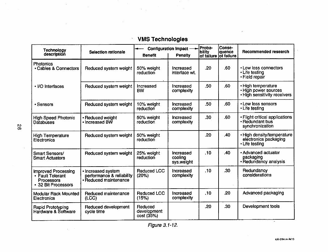
VMS Technologies
roo_
Technologydescrlptlon
Photonics• Cables & Connectors
• I/O Interfaces
• Sensors
High Speed PhotonicDatabuses
High TemperatureElectronics
Smart Sensors/Smart Actuators
Improved Processing• Fault Tolerant
Processors• 32 Bit Processors
Modular Rack MountedElectronics
Rapid PrototypingHardware & Software
Selection rationale
Reduced system weight
Reduced system weight
Reduced system weight
• Reduced weight• Increased BW
Reduced system weight
Reduced system weight
• Increased system
• performance & reliabilityReduced maintenance
Reduced maintenance(LCC)
Reduced developmentcycle time
--,--- Configuration Impact
Benefit I Penalty
50% weightreduction
IncreasedBW
10% weightreduction
50% weightreduction
50% weightreduction
25% weightreduction
Reduced LCC(20%)
Reduced LCC(15%)
Reduceddevelopmentcost (35%)
Increasedinterface wt.
Increasedcomplexity
Increasedcomplexity
Increasedcomplexity
Increasedcoolingsys.weight
Increasedcomplexity
Increasedcomplexity
Proba-bilityof failure
.20
.50
.50
.30
.20
.10
.10
.10
.20
Conse-quenceof failure
.60
.60
.60
.60
.40
.40
.30
.20
.30
Recommended research
• Low loss connectors• Life testing• Field repair
• High temperature• High power sources• High sensitivity receivers
• Low loss sensors• Life testing
• Flight critical applications• Redundant bussynchronization
• High density/temperatureelectronics packaging
• Life testing
• Advanced actuatorpackaging
• Redundancy analysis
Redundancyconsiderations
Advanced packaging
Development tools
Figure 3.1-12.
spb-2J94-re-Ad 13
ro..,j
Technologydescription
Reusable Software
Integrated Tool EnvironmentReliability & Performance
• Requirements & Specs
Subsystem Utilities Integration
Technology (SUIT) •Integrated Closed ECS
• Integrated Power Unit• Thermal & Energy
Management Module
Improved Hydraulic SystemConcepts
• Variable Pressure HydraulicSystems
• Variable Area Actuators• Power/Control by Light
More Electric Airplane Concepts• Electromechanical Actuators• Electrohydrostatic Actuators• Integrated Actuator Packages
Integrated Flight & PropulsionControl
• Surface Reconfiguration• Thrust Vectoring• STOVL• Optical Air Data• Flush Port Air Data
VMS Technologies (concluded
--,-- Configuration Impact _ Proba- Conse-blllty quence
Benefit I Penalty of failure of failure
Reduced Reduced .30 .30development developmentcost cost (25%)
Reduced Reduced .50 ,30development developmer_tcycle time & cost cost (25%)
50% weightreduction .30 .50
maintenancecost
Selection rationale
• Reduced weight• Increased energy
utilization• Reduced
Increasedvehicleperformance
Reducedmaintenancecost
Improvedperformance
5% increasedperformance
10% reducedmaintenancecost
10% increasedperformance
Increasedcomplexity
Increasedcomplexity
Increasedcomplexity
.60 .60
.50
.02
.50
.40
Recommended research
Modular softwaredevelopment tools
Abstract representationof system functionalityand requirements
Physical & functionalintegrationSuitability of differentfluidsEnergy utilizationAdvanced packaging
Energy optimizationHi._h powered, highrehability opticalsources
Reliability & lift testing
• Flight control surfaceredundancy
• Vehicle performance• Advanced control
laws
Figure 3.1-13.
- spb-2/g4-re-Ad 14
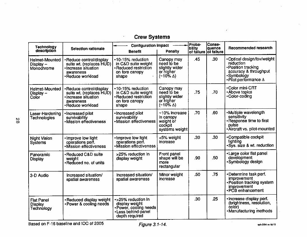
Crew Systems
POCO
Technologydescription
Helmet-MountedDisplay -Monochrome
Helmet-Mounted
Selection rationale
• Reduce control/display
•suite wt. (replaces HUD)Increase situationawareness
• Reduce workload
Display -Color
Laser-HardeningTechnologies
Night VisionSystems
PanoramicDisplay
3-D Audio
Flat PanelDisplay
; Technology
• Reduce control/display
suite wt. (replaces HUD)Increase situationawareness
• Reduce workload
• Increased pilot
.survivabilityMission effectiveness
• Improve low light
• operations perf.Mission effectiveness
• Reduced C&D suite
weightReduced no. of units
Increased situation/spatial awareness
• Reduced display weight• Power & cooling needs
Configuration Impact
Benefit Penalty
• 10-15% reductionin C&D suite weight
• Reduced restrictionon fore canopyshape
• 10-15% reductionin C&D suite weight
• Reduced restrictionon fore canopyshape
• Increased pilot
•survivabilityMission effectiveness
• Improve low light
• operations perf.Mission effectiveness
>25% reduction indisplay weight
Increased situation/spatial awareness
°>25% reduction in
display wei_thtPower, cooling needs
• Less behind-paneldepth required
Canopy mayneed to besli_lhtly widerornigner(-1o%A)
Canopy mayneed to be
sli_lhtly widerornigner(~10% A)
~10% increasein canopyweight orcockpitsystems weight
<5% weightincrease
Front panelshape will bemorerectangular
Minor weightincrease
_-- Proba-blUtyof failure
.45
.75
.70
.30
.90
.50
.30
Conse-quenceof fallure
.3O
.70
.60
.30
.50
.75
.25
Recommended research
• Optical design/fov/weightreduction
• Position trackingaccuracy & throughput
•S_mbology• Pilot performance A
• Color mini-CRT•Above topics-Color-coding
• Multiple wavelengthsensitivity
• Response time to first
•pulseAircraft vs. pilot-mounted
•Compatible cockpitlightin_
oSys. s=ze & wt. reduction
• Large color flat paneldevelopment
oSymbology design
• Determine task perf.improvement
• Position tracking system
improvementPCB enhancement
• Increase display perf.(brightness, resolution,color)
• Manufacturing methods
Based on F-16 baseline and IOC of 2005 Figure 3.1-14. " ,pb.2,_.,o_15
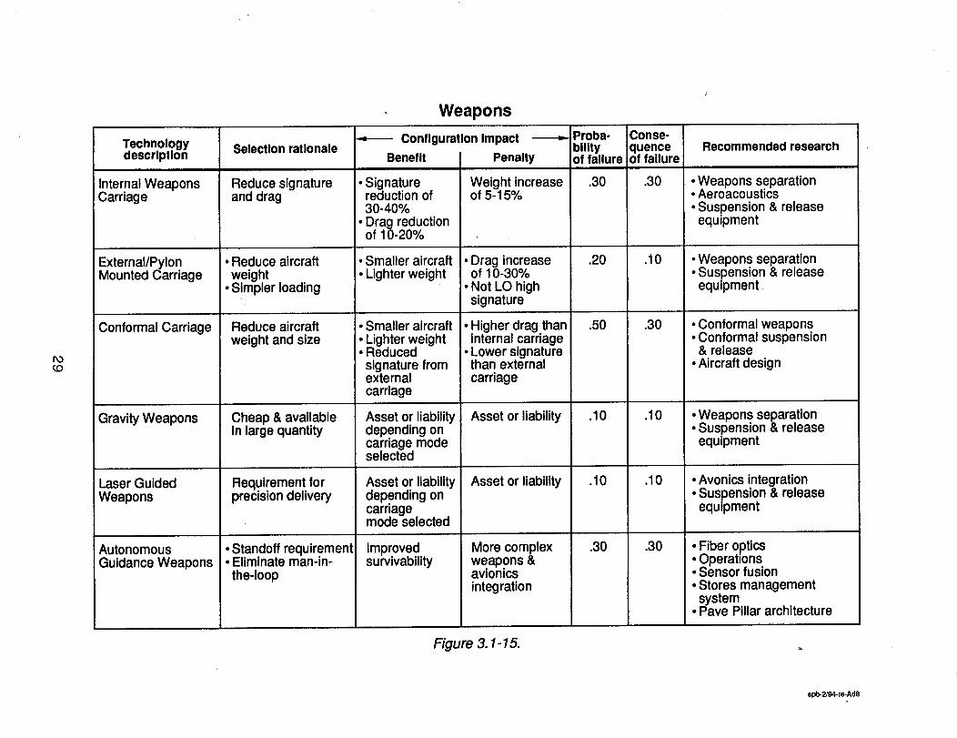
Weapons
PocO
Technologydescription
Internal WeaponsCarriage
External/PylonMounted Carriage
Conformal Carriage
Gravity Weapons
Laser GuidedWeapons
AutonomousGuidance Weapons
Selectlon ratlonale
Reduce signatureand drag
• Reduce aircraftweight
• Simpler loading
Reduce aircraftweight and size
Cheap & availablein large quantity
Requirement forprecision delivery
• Standoff requirement• Eliminate man-in-the-loop
Configuration Impact
Benefit I Penalty
!. Signaturereduction of30-40%
,. Drag reductionof 10-20%
• Smaller aircraft • Drag increase• Lighter weight of 10-30%
• Not LO highsignature
• Smaller aircraft• Lighter weight• Reduced
signature fromexternalcarriage
Asset or liabilitydepending oncarriage modeselected
Asset or liabilitydepending oncarriagemode selected
Improvedsurvivability
Weight increaseof 5-15%
• Higher drag thaninternal carriage
• Lower signaturethan externalcarriage
Asset or liability
Asset or liability
More complexweapons &avionicsintegration
Proba-bilityof failure
.30
.20
.5O
.10
.10
.30
Conse-quenceoffallure;
.30
.I0
.30
.10
.10
.30
Recommended research
• Weapons separation• Aeroacoustics
• Suspension & releaseequipment
• Weapons separation• Suspension & release
equipment
• Conformal weapons• Conformal suspension
& release• Aircraft design
• Weapons separation• Suspension & release
equipment
• Avonics integration• Suspension & releaseequipment
Fiber opticsi OperationsSensor fusion
• Stores managementsystem
• Pave Pillar architecture
Figure 3.1-15.
spb-2/94-re-Ad8
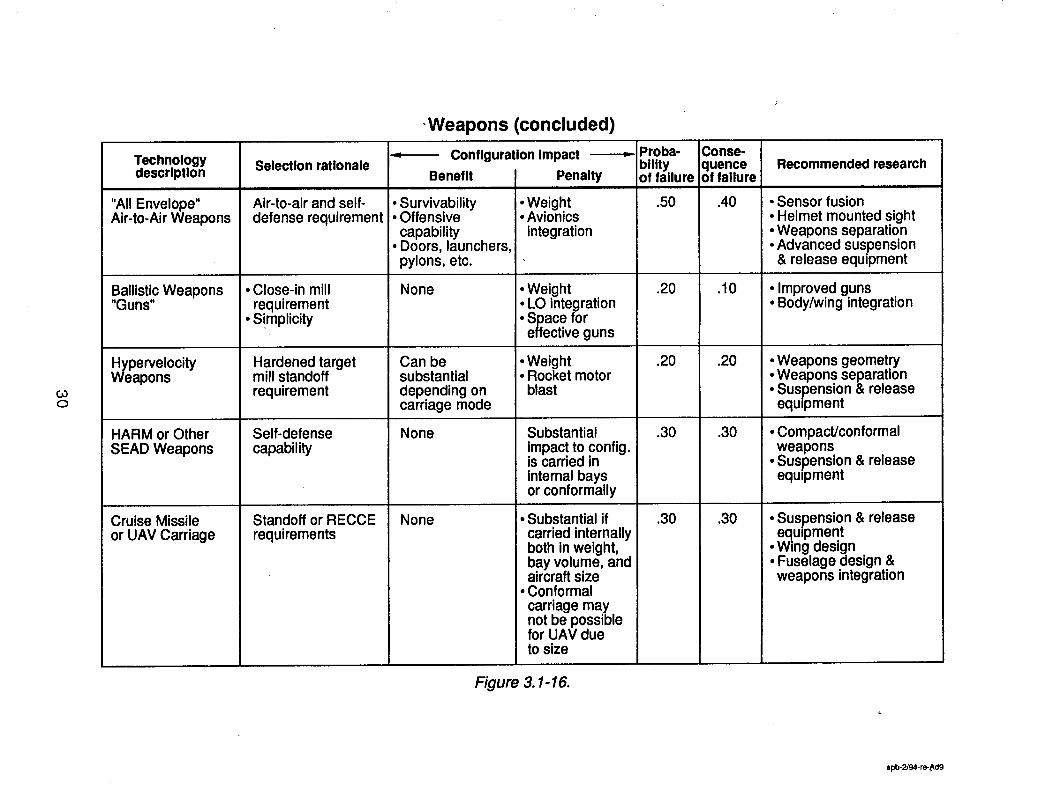
,Weapons (concluded)
COO
Technologydescription
"All Envelope"Air-to-Air Weapons
Selection rationale
Air-to-air and self-defense requirement
Configuration Impact
Benefit I Penalty
• Survivability• Offensivecapability
• Doors, launchers,pylons, etc.
Ballistic Weapons"Guns"
YePervelocityapons
HARM or OtherSEAD Weapons
Cruise Missileor UAV Carriage
• Close-in millrequirement
• Simplicity
Hardened targetmill standoffrequirement
Self-defensecapability
Standoff or RECCErequirements
None
Can besubstantialdepending oncarriage mode
None
None
• Weight• Avionicsintegration
• Weight• LO integration• Space foreffective guns
• Weight• Rocket motorblast
Substantialimpact to config.is carried ininternal baysor conformally
• Substantial ifcarried internallyboth in weight,bay volume, andaircraft size
• Conformalcarriage maynot be possiblefor UAV dueto size
Proba-bilityof failure
.50
.20
.20
.30
.30
iConse-!quenceof failure
.40
.10
.20
.30
.30
Recommended research
• Sensor fusion• Helmet mounted sight• Weapons separation• Advanced suspension& release equipment
• Improved guns• Body/wing integration
• Weapons geometry• Weapons separation• Suspension & releaseequipment
• Compact/conformalweapons
• Suspension & releaseequipment
• Suspension & releaseeq.ulpment
Wing designFuselage design &weapons integration
Figure 3.1-16.
spb-2/g4.re-Ad9
1.0
0.9
0.8
0.7
ALI.Oa. 0.6
"" 05o
.Q 0.42
n
0.3
0.2
0.1
0
f//f/x/,
///////_
DEMNAL limit//11/I//1/111/11/I/1111/ "1111111/f
¢FSD limitY//////_ "///////, "/, !
,'_-- W
l °
0.1 0.2 0.3 0.4 0.5 0.6 0.7 0.8
Consequence of failure (COF)
Figure 3.1-17. Sample Technology Risk Assessment Cnteria
0.9 1.0
spi_7-7-re-Ad2
31
8'0
dOO - emlled to eouenbesuoo
9"0 _'0 _'0
g_o oLo
om
g_O >r
• r
g_o
!
6LOm:0 'LgO
9_ _ '80 '90 ;0 '8 LO
9] _ '_LO
OL3=
:_o '60
,_o 'Lo
gO 'L0=
9_0
II_l] OSd
11" n 1VA/IN::IO
Sel6OlOUq_/ sJO;_N3 IOJlUOO - |ue_ssessV _SlEI
0
0
t'o
WO c'0
£'0 _'0L'0 ¢'0
;'0 f:'0
9"0 9"0¢'0 9"0
L'0 9"0L'O 9"0
S9"0 S9"0
L'O 9"0L"0 L "0
"0 ¢'0I-"0 9"0L'O £'0
£'0 L'O"0 6"0
t'O £'0
t'O S;'O17"0 £'0
L'O L'O;'0 £'0L'O L'Otr'O 9"0t'O t'O
t'O t'O9"0 £'0t'O t'O
_'0
g'O
"0
t,'o._cr,=.
_'o _
c
9"0 _
Z'O
9"0
6'0,
(_od) (_oo)e.mlled e,mlled
IoAllllqeqo_d
_0 I §upoloeh IsmqJ. OlPlnld
ii_iii]! _!_!!_!i_iii_iiiii::i::iii::!!i!i::!!::iiii::::::_::::ii!::!i!ii!ii::iii!_!i!!!!iiiiiii:::_i!_¢_O I $e)leJIS esoN §Ullelnol_V
I UOllOnS ApoqeJodL_O I §UlMOlS lois ApocleJod
0_0 I UUlMOI8 ler ApoqeJod6LO I eulqo flul|elnOlIJV8to I leqeJIS ApocleJOd 6UllelnOlNV
...........................................................;_p.ii.ii_iii_iiiiiii!iiiii!i_i_i!i_!_!_i!i_::!::iiii_i_iiiiiiiiii_iiiiiiiiii!i!M!Mii_i::::_::::MiM_i_i_i_i_i_;_......................._.!::i;:..........................;::.,..:_tl.O I 4eppnl:l qllM 1181 leOllJeA£1.0 I §UlM eouePlOUl elqel,mA
ttO I0_o I
zo I9o Iso I
iii!i!!iiii!iiiiiiiiiiiiii!!ii!ii!!iiiiii!ii]_i|ei_0_j_i!i_i_Jole^el] qtlM lie1 le;UOZlJOH
leqeJqpeedsIsJellodS
tueppnu Be.ta
BUlMOI8 UUlM lellueUueJ.BUlMOl81UOllons eUp=l BUlPee'l
seOlAeO eUP3 UUllleJjjUulPee'l eno,lod
eeoelJns IOJluoo uMoI8
]]_]i ::ill!]i_!iii!iM]i_i]i_i::i]i_i::!]i::i::!]!]!i!!!i!i!iiiiiiiiiii!iiii_.[.e.,i_ii_i!_ i_iii_ie_il' o'1.......... edel:l ,e^neuew eUp:1 I_Ullle,J.I
zo! ,uo.mUi.LJiii_i_:_!i_iiiiiiiiiIiiiiiiiiiiiiiiiii!i!i!i!iii!i!i::_!iiiii::i_iii::_`_..__i|i !_::::i.ti._i!_::!...I...__1
-- I__ I
,,Im Im I_ I
i
SUOlteJn§llUOO
,,U§lnP lulod,, SOY OlUl UOlleJodJOOUl Jo|I_loelee smell lueseJde4 ImeJe pepeqs :eloN
well ABOlOuqoe.L
O4CO
s;Old dO0 _.-IOd
O.1
OQ
Technology Item
Note: Shaded areas represent Items selected
for incorporation into ADS *'point design"
confl_luratlons
Vortex FlapVariable Camber/Mission Adaptive WingNatural Flow Wing
Porous Lifting Surface Technolo................................................... gY.. ....................
Hybrid Laminar Flow SystemForward Sweep Wing Technology
IHPTET Gen 5 Engine Technologies
Variable Cycle Engine TechnologiesF100/Fl10 Derivative Engine TechnologyFllg/F120 Derivative En Ins Technolo.............................................g.....................gY .....
wm
1
A1A2A3
A4
A6
A7
P1
P3
P4PS
i!!!i_!i!i
POF_COF P_
Coneequenc_of
Failure
(COF)
Probablllt'of
Failure
(POF)
0.2 0.30.3 0.3
0.3 0.30.4 0.60.3 0.2
0.3 0.40.5 0.4
0.1 0.40.5 0.6
0.3 0.20.3 O.2
0.3 0.30.2 0.5
"0.9
0.8
0.7u.£
|
2 0.6_=_8
U.
"6 o.s
.Q
_J 0.4
0.3
0.2
0.1
0
Risk Assessment - Aero & Propulsion Technologies
A4 P2
DEM/VAL Lh
pl
P1 A6=, ,,=
FSD Llml A2, A3,
A [A5, P3
,.,.
_=,,.J
i,z.
P5
P4
A7
_s
,.,J
<
=ZW
Q
0.2 0.4 0.6 0.8
Consequence of Failure - COF
Figure 3.1-19
Page 1
POFvsCOFPlots
CO
O0
o_;
Teohnology Item
Note: Shaded areas represent items selectedfor incorporation Into ADS "point design"
confl_luratlons
Advanced Aluminum-Lithium Alloys
Advanced Titanium AlloysPowder Metallurgy - Current Materiels
Ilntermetel Ceramic
IRereEarth AIIo_s - Sapphirei_5_!i_i__ii_iii_ii_i_i_ii_ii_i!i_iiiiiiiii::i_iii::i_iiiii_i::i_:iiiii_iiiii!i!iii_iiiiiii!iiiIBoron Based CompositeKevlar Based Composites.:_._._._.": _.._"" ":''";"' ....:.....:...:::... _...:.:...:..._:_,._.._"::.....:.........::...+.+:.......:...:...:::::;;_;:;::::: ............:::::: ::::: :::::.................::::: :::: ::: :_::_
_.dvanced Resins
__ii_!_i_ii_iii_iiiiiiiiii_:iiiii_!i!ii_ii!!i!i!!!i_!_!!ii!i_ii!_!_i!i!i!_:!!!_!_!!__iiii_i_iiiiiii_iiiiiii_ii!i!iiiiiiiiiii_i!iiiiii_iiiiiii_iiiiiiiii_iii_ii_i_!iii!i!_i_iii_!_!i!i!i_iiiiiiii_iii_!i
,Advanced Manur 0 - Composite Welding.............._":":_:_"'iii_'": _::': ................................,'_;'.';.-/',',", .',.",'.'.'.'I'."." ."".'.'.'.".'.. "".'.'..,"" "
Advanced Techniques - IssogrldAdvanced Tsehnlques - Column Core_iii_5_iii_iiiZi!i_ _.i.'_iii!iii!i!iii!i!i!iii!iiiii!i!i!i!iiiiiii!iiiiiii!iiiii!iActive Flutter Suppression
Aeroelasti© Tallorln_
Smart Structures
rr
LUm
Z
51
$2S3
iii_ii:i_S5$6
$8
S9
s_
$19
S20
S22823
S26
Consequenc_of
Probablllt
ofFailure Failure
(COl:) (POF)
0.5 0.5
0.5 0.50.5 0.5
0.5 0.50.5 0.7
0.7 0.60.1 0.50.7 0.3
0.5 0.50.3 0.30.3 0.3
0.1 0.30.3 0.3
0.3 0.30.1 0.30.1 0.30.1 0.3
0.3 0.50.3 0.5
0.3 0.50.3 0.50.0
0.3
0.7
0.30.5 0.50.5 0.5
0.7 0.7
U.O
t
_=a_U.
o
o
Risk Assessment - Structures & Mat'ls Technologies
0.9
0.8
0.7
0.6
0.5
0.4
0.3
0.2
0.1
Figure 3.1-20
=$5 =$26 _$22
IS6
DEM/V__ALLIn it $18. $19 $1, $2, S3
$7 R_0 R_I $4, S9; $24, S25
FSDLimlt $10, $1_ S13 $8
$12, $15 $14, S;!3$16, $17
.J
U)IL.
0.2 0.4 0.6 0.8
Consequence of Failure - COF
Page 5
O3
Technology Item
Note: Shaded areas repreaent items selectedfor Incorporation into ADS "point design"
confl_iuratlons
_ii_i!ii_i!ii__i_iii_ii_iii_iiiii_i_iiii!i_iiiiiii_iiiiiiii_iiiiiiii!i_iiiii!iiiiiiiiiiiiiiCommon RF Modules
_i_i!_i_iiiiii_illiiiiiii;i!iiii!i_i_i_ii_!i!iiiiiiii!i;_i_iiii!i!iii!iiii_iii_iiii!i_iiii_iiii;i_ii_iiiiii!ii_i!ii_ii_Subsystem Utilities Integration Tech. (SUIT)Integrated Closed ECSIntegrated Power UnitThermal & Energy Management Module
Variable Pressure Hydraulic SystemsVariable Area Actuators
Electrohydrostatlc Actuators
Surface Reconflguratlon
Photonlca - Cables & Connectors)hotonlcs - I/O Interfaces
>hotonlcs - Sensors
High Speed Photonlc DatabusesHigh Temperature ElectronicsSmart Sensors/Smart Actuators
:ault Tolerant Processors:)2 Bit Processors
Rapid Prototyplng Hardware and Software
Integrated Tool Environment
rrw
m=!
Z
ii!iiii_ii::iii::
i=:ii_::ii
iiiiiiii_)iiiiE6
::i_iiii_ii!ii::V2V3V4
V5V6
V7
VlO
V12V13
iiii_iii_iV15V16V17
V18
V19V20
V21V22
w4
V26
POF vs COF Plots
Consequenc(o!
Probablllt
0.30.4
o!Failure Failure
(COl =) (POF)
0.1 0.20.3 O.50.3 0.50.3 0.5
0.4
0.8
0.3 0.30.5 0.30.5 0.30.5 0.30.5 0.3
0.6 0.60.6 0.60.6 0.6
0.5 0.50.5 0.5
0.5 0.50.4 0.2O.4 O.2O.4 0.2
O.6 O.20.6 0.50.6 0.5
0.6 0.3
0.4 0.20.4 0.10.3 0.1
0.3 0.10.2 0.10.3 0.2
0.4 0.40.3 0.5
"0.9
0.8
0.7
ILL
, 0.62_=
0.5
0.4n
n
o.a
0.2
0.1
Risk Assessment - Avionics & VMS Technologies
DEM/VAL LI_
FSD LI
E1
V_
0 0.2
E2, E3
It E4, V26
-E5
111t Vl
V24 V12
V14
3 V21
V2; _ V¢3M.
E6
Vll,V9, VIO
,V25
V2, V_
V4, v_
V13
V19E..I
.J
:o
V6 V7, V8
V16, V17
V18
V15
0,4 0.6
Consequence of Failure - COF
0.8
Figure 3. 1-21
Page 2
POFw COF Plots
(jo(3)
Technology Item
Note: Shaded areas represent Items selectedfor Incorporation Into ADS "point design"
configurations
Helmet-Mounted Display - Color
Laser-Hardenln_ Technologies
Panoramic Display3-D Audio
External/Pylon Mounted Carriage
Conformal Carrla_le
_._i_iW_d_i::_i_d_iiiiiiiiiiiiiiiiiiiiiiiiiiiiiiii!::_::iiiiiiiiiiiHyperveloclty WeaponsHARM or Other SEAD Weapons
Cruise Missile or UAV Carriage
n,-
W
m
:!
Z
D2D3
!!i_!_!!::D$
D6
W2
W3
W8
WO
W10
ii_i::ii!i
Consequenc|of
Probablllt'
ofFailure Failure
(COl:) (POF)
0.3 0.45
0.7 0.750.6 0.70.30.5
0.750.25
0.3
0.30.90.5
0.3
0.30.1 0.2
0.3 0.50.1 0.10.3 0.3
0.4 0.50.1 0.2
0.2 0.20.3 0.30.3 0.3
0.1 0.1
0.9
0.8
0.7
U.
, 0.6z
0
0.4
D.
0.3
0.2
0.1
Figure 3.1-22
Page 4
Risk Assessment - Crew & Weapons Technologies
D5
D2
'D3
DEM/VAL LI _lt _W3m
D1
N6
D6
FSD Limit
W_, W7
W_, Wll
D7
W8
-n4, Wl wsW9, WlO
s.,J
,:_ -J
,,= ,,
0.2 0.4 0.6 0.8
Consequence of Failure - COF
1
3.2 Technologies used in Agility Study Configurations
The technology elements selected to be used for each point design configuration are shown onTables 3.2-1 and 3.2- 5. The majority of the chosen technologies are common to all configurationswith the only exceptions being in the "Control Effectors" selections. Also, most of the applied 'technologies risk levels are within the pre-established DEM/VAL limits. The exceptions being the all-moving canard, power/control-by-light and IHPTET Gen 6 engine technology.
Principal impact on configuration development resulted from incorporation of projected technologybenefits in five major functional areas.
• Main Engines Use of IHPTET "Gen 6" engines resulted in significant weight andsize reductions in the overall propulsion system (inlet, diffuser,engine bay and exhaust duct). Engine mass location within theairplane was less of a driving issue to achieve air vehicle balance.
• Avionics Principal benefits to airplane configuration resulted from reductionsin weight and volume for both the modules or units and theinterconnection system. Cascading benefit to the environmentalcontrol system for reduced cooling loads results in further volumereduction.
• Subsystems Expanded technology development in flight controls actuation,secondary power generation and control, ECS, andmanagement/integration of functional components are consideredas contributions to obtaining sufficient or expanded capability withinavailable or reduced airframe envelopes. The resultant anticipated isimproved installation density or volume utilization.
• Structural Materials Application of next generation composites, such as Titanium MatrixComposites (TMC), permits the implementation of unique designfeatures not feasible with conventional materials because offabrication complexity, environment limits, or weight impact onvehicle performance.
3.3 Weight and Cost Impact of Advanced Technologies
The Boeing developed parametric/statical Level 1 weight prediction methods used to estimate thegroup weights of the ADS "point design" configurations contain weight considerations for some ofthe technology items selected for incorporation into the designs. These items are not considered"advanced technology" and include items such as conventional ailerons, leading edge flaps or slats,all-moving horizontal tail, supercritical wing, electromechanical actuators, etc. Weight increments forincorporation of these devices are not specifically called out as special features. Tables 3.3-1and 3.3-2 show the advanced technology application weight effects. These features required specialconsideration, outside the standard method, when estimating their weights.
Projected weights for IOC 2005 avionics suites for the air-to-air and multi-role missions are shown onfigures 3.3-3 and 3.3-4. The air-to-ground avionicssuite was considered to be identical to the multi-role. Advanced technology assumptions used to generate these weights are presented on thetables. F-22 avionics weights were used as the base points and the advanced technology weighteffects were applied on a system-by-system basis.
37
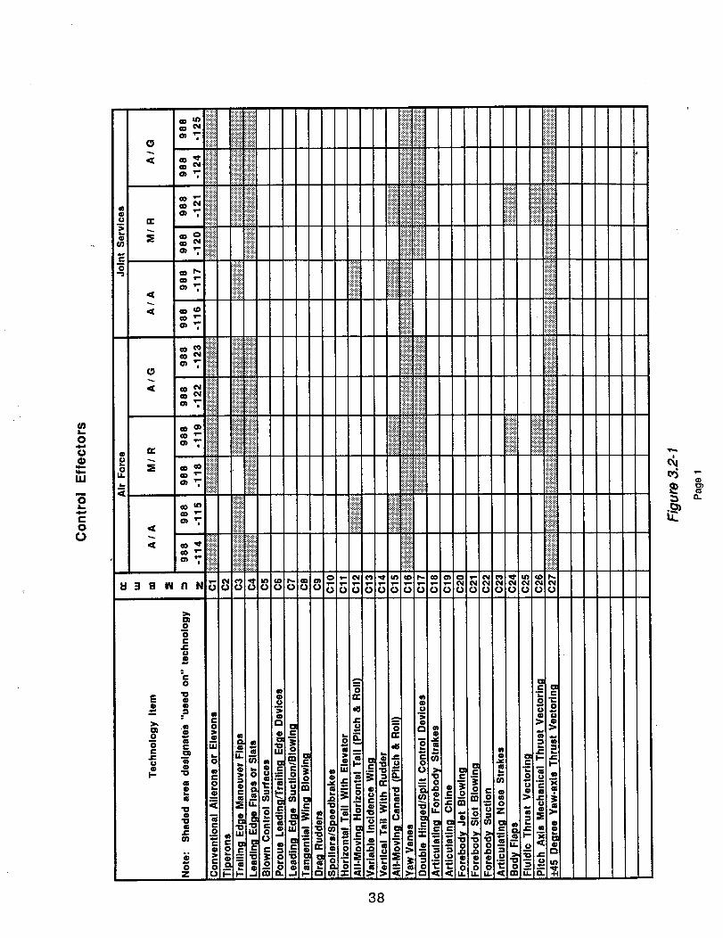
@
0
I.I.I
m
@L_
?.@
Q
0
0c
o
L.6
I:13 B M
E
O
0
U0I.-
_ iiiiiiiiiiiiiliiii iiiiiiiiili _i_ii_i_iiiiiiii .....
ilii i ..........'T. ii!iii!!! iiiii!iiiiiiiiiiiii iiiiiiiiii
_ ii .........................iliiiiiii•
_ • iiiiiii!i
_ i_i_!_i_iiiiiiiii i!iiiiiliiii!iiiiiiiiiiiiiiiiliiiiiiii:_:_:_ i!iiim!ii_iiii! ..........._.iii!iii_iiii!iil iiii!iiii_i_!_ii_!i!ililiiii
_'_' _'_'_'_'_ iiii!iiliiiiiiiiii!!!i!i!! iiiiiiii!..... !!!_i
_ i!i!iiiigl
o, "7. iiiiiiiiiiiii!iiiii! .................-,-,-,-,_,....v ::%::::%::::::
o_."'-i_i i iii_i i!iiii!ii,
"7,
3B
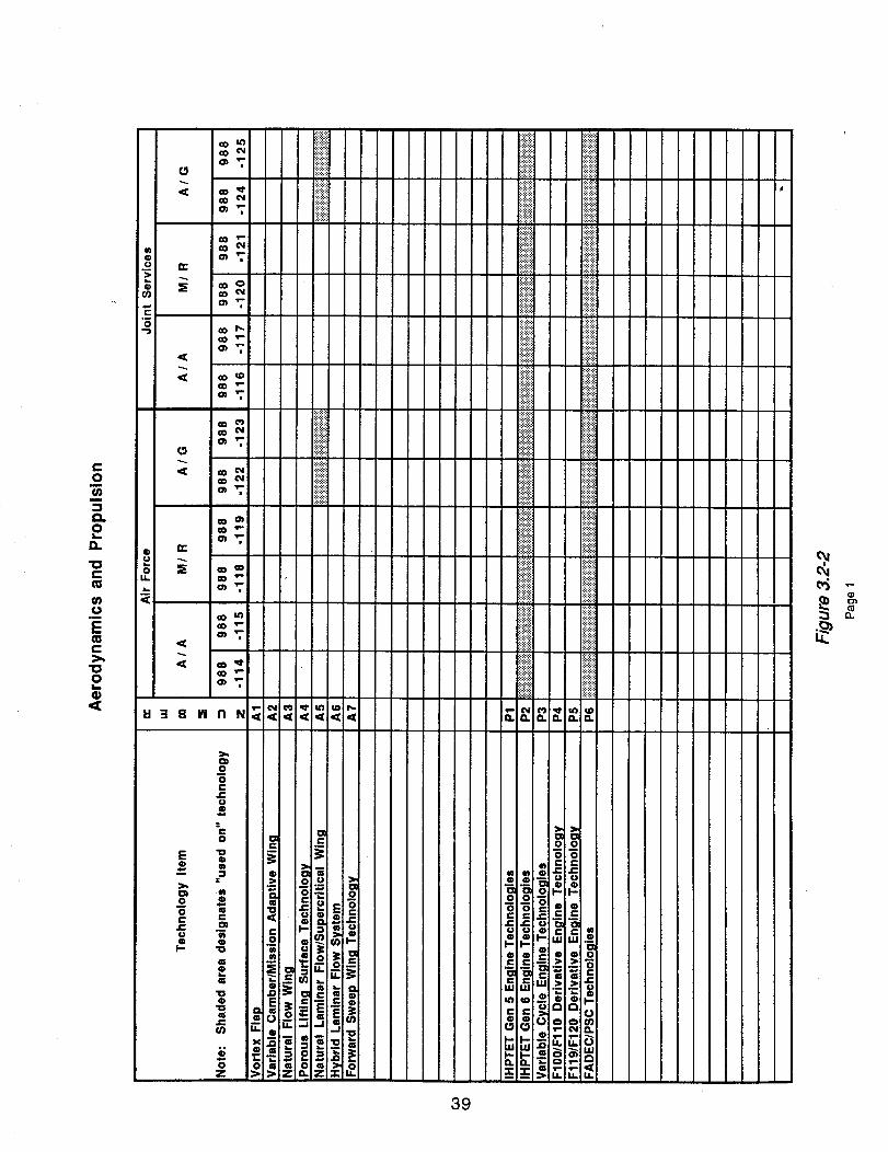
e-o
i
O.0i,i
o."0e=
(7)f.)
im
E
e,-_.,
o
G)
CO
O'J
: iiiiiiiii
a) o)_Jr"
O_ .t-
O
CO T-
i
s
@U
U.
|
a
e
g
|
|
ii!!!!i_i
iiiiiiili
iiiiiiiiiil i_i_i_i_i
:_:_:i:i:!: i
ili!_!!i!i
iiii!!iiii iiiiiiiil
_iiiiiiiiiiiiiii! _!_iii!iiii!i!i
....ii: iiili iii!iiii iiiiiiiil !iii!!!!:
iiiiiiiii '_""_iii_iiiil ,
iiiiiiii iiliiiiWii iii!i!;iiii!iii!i! _!!i!!!!_
fill}fill
i!!!!i!!i iii!i!iii:_:_:_:_: :_:_:_:_:
U3 B IMI
E
i
0
0
0
-" 0 _ m om
. _ _ o i_i_
_ _ _. !,_,uu__
0 ?-i
39
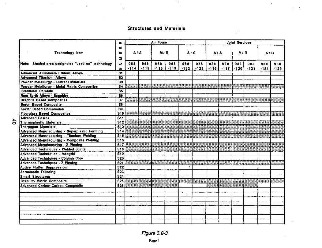
C)
Technology Item
Note: Shaded area designates "used on" technology
Advanced Aluminum-Lithium Alloys
Advanced Titanium AlloysPowder Metallurgy - Current MaterialsPowder Metallurgy - Metal Matrix Composites
Intermetal Ceramic
Rare Earth Alloys - SapphireGraphite Based Composites
Boron Based Composite
Kevlsr Based CompositesFiberglass Based CompositesAdvanced Resins
Thermoplastic MaterialsThermoeet Materials
Advanced Manufacturing - Superplastic FormingAdvanced Manufacturing - Titanium Welding
Advanced Manufacturing - Composite WeldingAdvanced Manufacturing - Z Pinning
Advanced Techniques - Welded Joints
Advanced Techniques - Issogrid
Advanced Techniques - Column CoreAdvanced Techniques - Z Pinning
Active Flutter Suppression
Aeroelastic TailoringSmart Structures
Titanium Matrix Composite
Advanced Carbon-Carbon Composite
Structures and Materials
Air Force
uJ
m
Joint Services
A/A M/ R A/G AIA M/ R A/G
=E
988 988 988 988 988 988 988 988 988 988 988 988
z -114 -115 -118 -119 -122 -123 -116 -117 -120 -121 -124 -125
$1
S2
S3
S4 iiiiiiiiiiiiiiiiiiiiiiiiii!}iiiiiiiiiiiiiiiiii}i;iiiiiiiiiiil}ili}iii!iiii}iiii!iiiiiiiiiiiiiiiiiiii}iiiiii!iiiiiil}iiiiiiiiiiii!::i!iiiiiii::ilili::ilil}ii::ilili::ii?:i::ii_i_iiii::ii!::i::!i!ii::_::iiiiiiii!i}iii!iii}iiiiiiii}iiiii::i!i::ili::iiiiiiiii::i::iiiiiii::iiiii::::iiiiii}:::}:iiiili::i::iiiii}iiiiiiiii}iiiiiiiii}iiiiiiili!i!::ii!ii::i::!iiii::i::!i!::i::iiiii::i::i::!::!::i::i::i::i::!::ili}::!ili_$5
$6.........,..........,.......... :,:.:+:.:.:.:+:.:.:.:. .:.:.:.:.:.:,:.:,:.:.:.:.:.:.:.!s7 :::::::::::::::::::::::::::::::::::::::::::::iiiiiiiiiiiiiiiiiiii;iiiiiiiiiiiiiiiiii}iiiiiiiiiii!iiiiiiiiiliii!iiiiiiiiiiiiiiiiiiiiiiiiiiiiiiii!!iii_iiiiiiiiiiiiiiiiiiiiiiii!iiii::iiiili;iiiiii::iiiii::iii::iiiiiiiiiiiiiiiil}iiiii!iiii!iiiiiiiiiiiiiiiiiiii!iiiiiiiiiiii::::::::::::::::::::::::::::::::::::iiiiiiiiiiiiiiiiiiiiiii}iii!iiiii::_i_!_::_i_i_i_i_!_i_i_i_i_!_i_iiii!}i}iii}iiiiiii}!iii!iiiiiiiii
S8
89
Sl 0 iiiiii!i}iiii!i!i}ii!iii}}iiiiliii!ii}!}iiii!iii!!iiiiiiiiiiiii!iiiiii!ii!iiiiiii!iiii}!i!}ii!i!}iiiiiiiiii}i!i!iii!iii!i!iii! ii}iiiiiiiiiiiiiiiiiii!iiiiiiiiii;iii!ili!ii!i!iiiiiiiiii!iliiiiiii!!i!ii!!}!ii!!iiii!!iiiiiiii}iiiiiiiiiiiil}iiiiiiiiiiiiiiiii}}iiiiiiiiiiiiiiiiiiiiiiiiiiiiiiiiiiiiiiiii!iiiii}!i!iiiiiiiiiiiiiiiiiiiii!iiiiiiiiiiiiiii!Sll
Sl 2 i!i!iiiiiiiiiiiiiiiiiiiiii}i!iiii!i}i}!iiii!iiii!i}!iiiiiiiiiiiiii!i!!!i}iii!!i!!!i}}i!i!i}i!i!i!iiiiiii!!!i!!!!!i!iii!ililiiiiiiiii!ii!}!i!!ii!i!i}!}ii}iiiiiiiiiii!iiiiiiiiiiiiiiiii}iiiiiiiiiiiiiiiiiiiiiii}iiiiiiiiiiiii!iiiiii}iiiiiiiliiii!iii!i!iiiilili!!i!iiiiiiiiiiiiiiiiiii:.iiiiiii!!!iiiiiiiiiiiiiii}i!i!iliiiiiii!ii!iliiiii!ii!iiiiiiiii!i!}i!!iiiii!iii!!}!i{iiiiiiiiiS13 iiiil}iiiiiiiiiiiiiiiiiil}iiiiiiiii!iiii!iiiii!i;iiiii}iiiiiiiiiiiiiiiii}iiiiili;!iiii;iiiiiii!iiiiiii;ii!iiiiiii}iiiiii}ii!;iiiiii!iiiii}iiiiiiiii!iiiiiiiiiiiii}i}iiiiiiiiiiiiiii!iii!iii!iiiiiiiiiii::ii!iiiiiiiiiii!ii::iiiiiiiiiiiiiiiiiiiiiiiiiiiiiii1.iiiii}iii}iiii!iii!iiiii!i.iiiii:!!iiiiiii!ii}i!i_i!i!i!ii_:_ii!i!i_i!i!!_i_i}iiiiiiiiiiii._iiiiiii:!_i}iiiii_i_iiiiiii;iiii
S14 iiiiii;i;i;i;i;i;i;iii;;;iii;ii:#:i::iiiii::ii!ii::_}}:#:i::i;i;i};}i;iiiil;iii;i!i!i;i;;;ii i;i;}i;iiiiiiii!ii;i;;;i;ii}i}ii;iii;ii;;i;!ii;iiiii};!iiiii;i;ili_i_i_ii::ii_::_i_i_i_i_ili_i_::_::ii!i;;ii;ii;i;;ii;;;iiiiiii;i;i;!ii;i;iii;ii;;i;i;!i}ii;ili;;ii!iiii::i!i::i::!i!iii_i_iiiiii:_iiiiii_i:_iii::_:_iiiiiiiiiii_:ii.}i_ii::iiiii:_i_iii_iiiii_:i:_ii-iiii::ii!iiii_i_:i_:iii_:i::iii_:i:_i:_•:,:.:.:.:.:+:+;.:.:.:.:.:.: .:.:.:.:.:,:.:,:.:,:.:.:.;.:,:*:. ::::::::::::::::::::::::::: :.:.:.:.:.:.:.:.:,;.;.:.:.:.;.:.: :.:.:+:.:.;.:.:.:.:.:.:.:.: :::::::::::::::::::::::::::::::::
Sl 5 i!i!!iiiii!;!iiiiiiiii!ii!!ili!iiiiiiiiiii!iii!}iiiii;}iiiiiiiiiiiiiiiiiiii;iiiiiiii!i!i!ili;;iiiiiiii!iii;i!i!ili!i!i!iii!i}i!i!ii!ii!i!i;i}}ii}iii!iiiiiii!iiiiiiiiiiiiiiiiiiiiiii}i}iiiiiiiiii}}i}iiiii}i}ililili}}}ii!!iii!iii}i!!!ii!}!}ii!ii!!i}!i}i!i!!i!i!iii!!!!i!i!ili}}ii}i!!ii;!i!i!i!}}i!!!i!iiiii!!ii}i}}ii!ii!iii!i!i!i!}!i!iii!i!i}i!i!ii;iii;il}ii;i;iiiiiiiiiiiii!}!}!;i
S16 L...........;....s17 iiiil}il}iiiiiiiiiiiii!il}ililiiiiiiiiii!}iiiiiii}i}iiiiii}ii!iiii}iiii!iiiiii!i!;iiii!iiiiiiiiiii!iiii!iiiiiiiiii!}ill_::_::_::::_::_::}iiiiiiiiiiiiiiiiiiiiiiiiiiii}iiiiiiiiiiiiiiiiiiiiiiiiiiiiiiiiiiiiiiiiiil}i}ii!ili!ii!iiiiiiill;iiiiiiiiiiii!iiiiiiiiiiilli}iii!iiii}}iiiiiiiiiiiiii!!ili!iiiiii!iiiiiiiiiiiiiiiiiiiiii!iiiii!i}iiiiiiiiiiiiiiiiii!iii!is18 iiiiiiiiiiiii::iiiiiiiiiiiiiiiiiiliiii::iiiiiiiiiiiiiiiiiiiiiiiiiiiiiiiiiiiiiiiiiiiiii!iiiiiiiii::iii::iiiiiiiiii!iiiiiiiiiiiiillI_ii_!i_iiiiii!i!!!iii!_ii!_iii_!_iii_ii_i_i_i!!i_ii__!!_i!_!!!_!_ii!_!ii_i_i!_ii!i!!_iiii_i_ii_i_$19
S20S21 :_iiiii::iiii!iiiii!iiiiiiii::iii::!i}iii!!iii!!!ii!ii_:!!i!!ilililii::iiiiiiiiliiii::iiii:i!i_:iiiiiii_:iiiiiiliiii!i!iii!ii!i!!!ii!i!iiiiiii!iiiiiiiiiiiiiiiiiiii_:i;iii::iii::i::i!i!iii::i!iii::i::iiiii!i::iii!iii!i!il;;ili!i}!}ili!i;ilil_:_:::::::::_:_:::::::_:::_:::_::._.:::::_:::_:::::_:_:_:::_:::::::_::::_:::_::_::::::::::::._:::_:i_i_!:i_:i_i_i_i:_i_i:_i_i_i_i_:_i_i_i_i_i_iii:i:!:i:_:i:i:i:i:i:i:!:i:i:i:i:iiiiiii::i::iii::i::i::iii::i::iii:i::iiiiiiiii::i::iii::iiiii::i::i::iii::$22
$23
$24
s25 }iiiiili;ili!i!il;iiii!!iil}iiiiiiiiiiiiii;;iiiiiiiii;iiiiiiiiiiiii!iiiiiii!iiiiiiiiiiiiii;;iii)iiiiii}iiiiii!ili}ilililil}iiiil_........_.......................iiii!iiiiiii!i!i!iiiiiiii::iiii}i!ii}iii!!!i!i;!!i!i!!}iil}}!!i}!i!!}!!i!i!i!i!}!ilili!i!iiiiiii!ii!ii}}i!}iiii!}i!!ii;iii;ilili}i;iiiiiiii)iii)i;};ii::::::::::::::::::::::::::::_s_:}}iiiiii}i;))iii;i};ii}i}iiiiiiiS26 iiiiiiiiiiiiii!iiiii!iii!ili!iiii!i!iiiii}!!ililiiii!!;iiii!ii!iiii!i!i!i!iii!ii!}i!iii!iiiiiii!i!iiiiiiiiiiiiii!!i!ii!!!}iii!i ii}iiiiii:iiiiiiiiiii}i:_iiii:iiii.!iiiii:iiiiiiiiiiiiiiii:!iii:iii_iii..iii:iiiiiiiiiiiiiiiii;iiii_ii:_iiii:_ii_ii_ii::_i}i!ii::ii?i!i_i!ii
Figure 3.2-3
Page 1
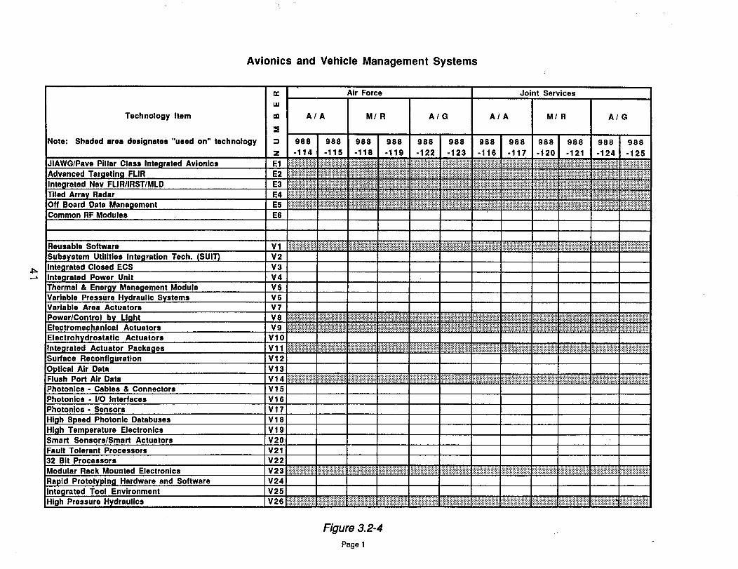
TechnologyItem
Note:Shadedareadesignates"used on" technology
JIAWG/Pave Pillar Class Integrated Avionics
Advanced Targeting FLIR
Integrated Nay FLIR/IRST/MLD
Tiled Array RadarOff Board Data ManagementCommon RF Modules
Avionics and Vehicle Management Systems
:f
::)
z
E1
E2
E3
E4
E5
E6
Air Force Joint Services
A/A M/R A/G A/A M/R A/G
988 988 988 988 988 988 988 988 988 988 988 988
-114 -115 -118 -119 -122 -123 -116 -117 -120 -121 °124 -125
_i!i!;_!_!:_iii_i!iiiiiiiiiiiiiiili:_i::iii;:iiiiiiiiiiiiiiiiiiiiiii::iiiiiiiiiiiiiiiiiiiiiii;:iiiiiiiiiiiiiiiiiiiiiiiiiiiiiiiiiiii!i!ii_iiiiiii::ili::ili:_ii!i!iiii::iii::i!ii!::!ii!!!iiiiiii!ili:_iiiiiiii!_iiiii!iiiiiiiii!i!iiiii!iii!iiiiiiii!ili!ii!!iii!iiiiiiiiiiiiii_:_:_:_:_:_:_:_:_:_:_:_:_.....::::::::::::::::::::::iiiii!i!iiiii!ili!iiiiiiiiiiiii::i::iiiiiiiiiiiiiiiiiiiiiiiiiiiili!iliiiiiiiiiiiiiiiiiiiiiiiliiiiiiii!!!iiiii!iliiiiiiiii!!illiiiiii!iiiiiiiiiiiii!iliiiiiiiiiiiiiiiiiiiiiiiiiiiiiiiii!ii!iiiiiiiiiiiii!!i!iiii!iiiii!iiiiiiiiiliiiiiiiiiiiiiiiiilili!iiiiiiiiiiiiiiiiiiiliiiiiiiiiiiiiiiiiiiilii!iiiii!iiiiili!ii!!iliiiiiiili::::::::::::::::::::::::::::::::::::::::::::::::::::!iiiiiiiiiiiiiii!i!iiiiiii!!!i!iiiiiiiiiiiililiiiiiiiiiiiiii_i;:iii::iii_iiii!iiii_iii_i::!_iiiiiiiiiiii!iiiiiiiiiiiiiiii!il!iiiiiiiiii!::iiiiiiiiiiiiiiiiiiiiiii::i_:i!iiiiiii:_i_:iiiii::iii::i::i::i::_:_ _ii_i_!iii_i_i:_i_iiiiiiiii:_i:_iii_i_i:_i:_iiiiiii_i_iiiiiiiiiiiiii_ii_i:_i:_iiiiiiiiiiiiiiiiiiiiiiiii::iiiiiii_i!i!i!iiii_iiii!iiiiiiii_:i::i::i::i::i::iii::iiiiiiiiiii::i!i::ii!ii!iiiiiiiiiiiiiiiiiiiiiii!i!i!i!i!iii!iiiiiiiiiiliiiiiiii!ii!!iiiii!iiiiiiiiii!iiiii!iiii::iiiiiiiii_:iiiiiiiiii!i!ilil:.:.:,:,:,:-_.:,:,:,:-_-:,:.:,:.;:_::_i_::_::_::_;:_i_!_::_::_i_i_!_::_::_!ili!iiii!ii!!ii!i!ii!i!iiiiiiiii!i:.:-:.:.:._.:._.:.:.:.:.:.:.:.:_i_i_::_::_i_i_::_!_i_i_i_::_::_i_.:.:,:.:.:-:._.:-:-:.:.:.:-:.:.:.::_!_!_i_::_!_::_::_!_i_::_::_i_i_i_::_::!iiiiiiii!ii!iiiiii!iiiiii!i!!!.:.:.:._.:.:-:,:,_.:.:,:.:-:.:.:i_::_;:_::_::_i_i_i_i_i_::_i_i_i_i_i_::iiiiiiiililiiiiiiii!iii!!ililililiiiiiiiiiiiiii!iiiiiiiiiiiiiiiiiiiiiiiiiiiiiiiiiiiiiiiiiiiiiiiiiii_:ii!iiiiiiiiiiiii!ililiiiiiiiiiiii!iiiiiiiiiiiiiiiiiiiiiiiliiiiiiiiiiiii!ii!ii!ili
::i_i_!_i_i_!_!ii_iii_i_iii_i_i_iiiiiiiiiiiiiiilililiiiiiii!ii!iii!iiiii!iii!ii!ii!!!iiiiiiiiiiiiiiiiiiiiiiiiiii!i!i!ii!!!iiiii!iiiiii!i!iiiii!iiiiiiiiiiiiiiiiiiiiiiiiiiiiiiiiiiiiii!ii!!iiiiii!iii!iiiiiiiiiiiiiiiiiiiiiiiiiiiiiiiiiiiiiiiiiiiiiiiiiiiii-liiiiiiiiiiiii!iiiiiiiiiiiiiiiiii!iiiiiiiiiiiiiiiiiii!iiiiiiiiiiiiiiiii!ili!i!iiiiiiiiiiiiiii
Reusable Software
Subsystem Utilities Integration Tech. (SUIT)
Integrated Closed ECS
Integrated Power Unit
Thermal & Energy Management Module
Variable Pressure Hydraulic SystemsVarlable Area Actuators
Power/Control by LightElectromechanlcal Actuators
Electrohydrostatic Actuators
Integrated Actuator Packages
Surface Reconfiguration
Optical Air DataFlush Port Air Data
Photonlcs - Cables & Connectors
Photonics. I/O Interfaces
Photonics - Sensors
High Speed Photonic Databuses
High Temperature ElectronicsSmart Sensors/Smart Actuators
Fault Tolerant Processors
32 Bit Processors
Modular Rack Mounted Electronics
Rapid Prototyping Hardware and SoftwareIntegrated Tool Environment
High Pressure Hydraulics
V1
V2
V3
V4
v5
v6
v7V8
V9
V10
Vll
V12
V13
_!_!_!_i_i_i_i_i_i_i_i_i_i_i_!_i_i_i_!_i_i_!_!_i_i_i_i_i_i_ii_iii!iiiii!i!i!iiiiiiiiiii!iiiii_iliiiiiiiiiiiii_i_i_iii_iii_iiiii_i_i_i_i_i_i_i_i_i_i_i_i_i_iiiiiii!iiiiiiii!i!!ii!iii!iiiiiiliiiiiiiiiii!iiiiiiiii!i!iiiiiiiiii!!ii!iiiii!iiiiiiiiiiiiii!iiiliiiiiiiiiii!iiiiiiiiiiiiiiliiiiiiiiiliiiiiiiiiiiiiiiiiiiiiiiiliiiiiiiiiiiiiiiii!iiiiiiiiil!iliiiiiiiiiiiiiiiiiiiiiiiiiiiiii!!iiiiiiiiiii!ii!!iiiiiiiiiiiii!!ii!iii!ii!!iii!ii!iliiiiiii!ii!i!!i!!!_iii_!iiiiiiiiii!iiiiiiiii!iiiiiiiiiiiiiiiiiiiiiiiiiiiiiiiiii!iiiiiiiiiiiiiiiiiiiiiiiiiiii!iiiiiiiiiii!iii!i!i!i!i!iiiiiiiiiiiiiiiiiiiiiiiiiiiiiiii!iliiiiiiiiiii!iiiiiiiiiiiiiiiiiiiiiiiiiiiiiiiiiiiiiiiii!iiiiiiiiiiiii!iiiiiiiiiiiiiiiiiiiiiiiiiiiiiiiiii!iiiiiiiiiiiiiiiiiiiiiiiiiiiiiiiiiiiiiiiiii!iii!iiiiii
:::::::::::::::::::::::::::::::::::::::::::::::::::::::::::::::::
i!!iiiii!ii!iiiiiiii!iiii!i!iiiiiiiiiiiiiiiiiiiii!iiiiiiiiiiiiiiiiiiiii!!ili!iiiiiii!iiiiii!iiii!iiiiiiiiiiiiiiiiiiiiiiiiii!i!!iii!i!i::iiiiiii::iii::i::iii::i::i!i:;i:.:.:.:._.:.:.:.:.:._.:.:,:.:.=.:._::_;:_i_i_!_i_i_i_i_;:_i_i_i_i_::_i_iiii!iiiiiiiiiiiiiiiiiiiiiiiiill!iiiiiiiiiiiiiiiiiiiiiiiiiiiiiiiiiiiiiiiiiiiiiiiiiiiiiiiii!iiiiiiiiiliiiiiiiiiiiiiiiiiliiii!iii:::::::::::::::::::::::::::::::................................................................._.:.:.:,:.:.:_:.:.:.:.:.:.:.:.;.
V14 iiiiiiii;iiiiiiiiiiiiiiiiiiiiiiiiiiiiiiiiiiiiiiiiiiiiiiiiiiii!iiiiiiiiiiiiiiiiiiiiiiiiiiiiiiiiiiiiiiiiiiiiiiiiiiiili!iiiii!ili!ii!iiii!!!i!!ii!i_i!iii!iii!iii_i!i!iiiiiiiiiiiiii_iiiiiiiiii_i_iiii!i!iii!!!!!i!!!iiiii!i!iiiii!iiiiiiiii_i__i_i__ii_i_ii_i!i_i_i_i!i!i_!_ii_i!i_!_i_i_ii_ii_i_i._i_i_iii.i.i_i_i.ii.i`_i.i`i.ii_i_i_i_i.i.i_i.ii_iiiiiiiiiiiiiiiiii_i_iii_iiiiiii_V15
V16
V17
V18
V19
V20
V21
V 2 2.............................................................. iiiii!ili_ii!!!ii_ii!iiiiiiiiilV23 iiiiiiiiii!iiiiiiiiiiiii!iii!!iiiiiii!iiiiiiiiiiiii iiiiiii!iiiiiiiiiiiiii iii!iiiii_iiiiiii_iii_i!i_!i_iiii__i____!_ii_i_iii__i_ii_iiiiiiiii_iii_i__i_iiii_ii_iiiiiiiiiiiii_iiiiiiiiiiiiii!!!_iii_i__!i_iiii!_i__iiiiii___iiiiiiiiiiii__!i!_iiiiiiiiiiii_iiiiiiii!i!!i_ii_i
V24
v25 ilililiiii!iiiililiiiiiiililiiii_v2__!_i_iiiii_!!iiii_i_ii_iiiiii!ii._iiiiiiiiiiiiiiiiiiiiiiiiiiiii_iii_iii_iiiiiiiiiiiiiii_i!iii_iii!i!_i_i_i!i_i_i_i_i_i_!ii!i_i!iiiiiiii!iii!iiii_iiiiiiiii;iii_i_i_iii_iiiii_iii_iii_!_i_i_i!iii_iii!i_i_iii_i_i_i_!_!_i_:_:_:::,i_iii_ii_iiiiiii_ii_i_i!_!i_::::,,,,_:::,:::,:::,,:_,,_,,,: _::::................
Figure 3.2-4
Page 1
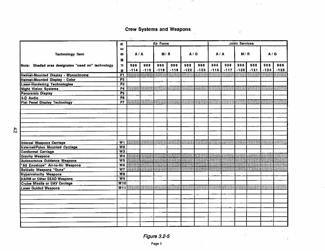
Crew Systems and Weapons
Po
Technology Item
Note: Shaded area designates "used on" technology
Helmet-Mounted Display - Monochrome
Helmet-Mounted Display - Color
Laser-Hardenlng Technologies
Night Vision Systems
Panoramic Display3-D Audio
Flat Panel Display Technology
Internal Weapons Carriage
External/Pylon Mounted Carriage
Conformal Carriage
Gravity WeaponsAutonomous Guidance Weapons
"All Envelope" Air-to-Air Weapons
Ballistic Weapons "Guns"Hyperveloclty Weapons
HARM or Other SEAD Weapons
Cruise Missile or UAV Carriage
Laser Guided Weapons
n-
m
:S
z
P1
P2
P3
P4
P5
P6
P7
Wl
W2
W3
W4
W5
W6
W7
W8
W9
Wl0
Wll
Air Force Joint Services
A/A M/R A/G A/A M/R A/G
988 988 988 988 988 988 988 988 988 988 988 988
-114 -115 -118 -119 -122 -123 -116 -117 -120 -121 -124 -125
i_i_i_i_i_i_i_i_i_i_i_iii_i_iii_i_i_i_i_i_i_iii_iiiiiiiiiiiiiiii_i!iii_iii!iiiiiiii!!iii!ii!iili_i_i_i_i_i_i_i_ii!_i_i_ili_ii_iiiii_!i!_!_i_i_i_i_i_iiiiiiiiili__i_ii_i_i_i_i_i_ii_iiii_iiii_i_iiiiiii!!iiiii!ili!i!i!il}i!iiiiii!i!i!iiiiiiii!iiiiiiiii!iii_}_i_iiii!iiiiii_!!iii!ii}ii_iil_!!ii!_i_i_iiiii_iiiiiiiiiiiiii}ii_!iii!i_ii!i}!iiii!iii}ii!iii_i!iiiiiiiiiiii_!iiiiiiii_i_iii!iiii
i!!ii!iiiiii!i!i}!iiiiiiiiiii!ii!iiii!!i!iii!i!iii!ii!i!ii!!i!i!iiiii!!!iiiiiiiiliiiiiiii;i;iiiiii_i_i_i_i_i_i_i_i_i_i_i_i_i_i_i_i_iiiii;!iiiiiii}iiiiiiiiiiiiiiiii!i!i!i!i!iiiiiiiiiii!i!iiii!!!!i!!ii_i_i_!_i_i_}_i_i_i_i_i_i_i_i_i_i_i_i_i_i_i_i_i_i_i_i_i_i_i_i_iiiiili}i}iiiiiii}iliiiiiiiilliliiiiiii!iiiii_ililili}i}iiiiiiiiiiiiiiiiiiiiiiiiii}iiiiiii}iiiiiil}iiiii!iiiiiiiiiiiiiiiiiii
_,_,_,_:_,_,_,_,_,_:_,_,_,_,_,_,_iiiiii!i}i!iiiii!}i!iiiili!ii!!!i!i_i_i_i_i_i_i_i_;ii_i_i_i_i_i_i_ii_iii_i_i_iii_iiiii_iiiiiiiii_iii_i_iii_i_iiiiiiiii_iii!iii_i!iii!i!i!}i!iii}i!iiiiiili!iiiiiiiiiiiii_i_ili_iiiiiii_iiiiiiiiiiiiiii_i_i_iiii}ii_iiiiiiiiiiiiiiiiiiiiiiiiiiiiiiiiiii_iiiiiiiiiiiii_i_iii!}i!iiiiii!!iiii!i!!!!!!i!iiiiiiiii!iiii!ii}!!iii!i!il}iiiii}iiiiiii!iiiiiii!iiiil}iiiii}i_:¸
............ ,..., ..
_ i_i_i_i_i_i_i_i_i_i_i_i_i_i_i_ifli!_i_!iiii_i_!_i_iiiii_iiiiili!iiiiiiiiiiiiil;iii}iiii;iiiiii}iiiii!iiiiiiiiiiiiiiiiiiiiiiiiliiiii_i_i_i_i_i_i_i_i_i_i_i_!_i_i!ilili!i}i}iiiiii;iiiiiiiiiiiiiiiiiiiiiiiiiiiiii}iliiiiii!;iiiiiiiiiiiliiiiiiiiililili;i}iii}i;iiiiiiiiiiiii}ii!i!!iiiil}iiiii!}!iii!i}ii!iiiii}ii!!i!;i!ii!i}i}iiiiiiiiiiiii!!iii!iiiiii':+:':'_':':':':'_':':':':':': ':':':':':'i':':':':':':':':':':" " ...... ":':':':':':':':':':'_':':':':':'
iiiiiiiiiiiiiiiiiiiiiiiiiii!iiiiiiii!!i}iiiililil}iiiiiiiiiiiiiiiiiiii}iiiiiiiiiiiiiiiil}iiiliiiiiiii!iiiiiiiiiiiiiiiiiiiiiiiii!iiiiiiiiil}ii}iiiiiiiiiii}iliiiiiiiiiiiiiiiiiiiiiiitiiiiiiiiiiiiiiiiiiiii!iii!i!ii!iiiiiiiiiiiiiiiiiiiiiiiiiiii}iiiiiiii}ii!iiiiiiiiiiiiiil}i}iiiiiil}iiiiiiiiii::i::i_i_i_}_i::i_i_i_i_!_i::i_i_i_i_iiiiiiiiiiiiiiiiili}iiiiiiiiiiiliiiiiiiiiiiiiiiiiiiiiii!ii!}ii}iiiiiiiii}!iiiiiii!}_!!}i}i!iii!iiiiii::}iiiiiii!iiiiiii}i}il'_i':!iiiiiii}iiiiiii}ii}iiiiiiiiiii}ii!iiiiiiiiiiiiiiiiii!i}i}iii!iiii!i!iiiiil}_iiiiiii_i::iiiiiiiiiiiiiiiiiiiiiiiiiiiiii!iiiii}ii}iiiiililiii!ilil}!iiiiil}iiiiiil}!}iiiiiiiiii}_iiiiiiiiii}iiiil}iiil_i_i_i_i_i_i_i_i_iiiiiiiiiiiiiii_iiiiilili_iiii}iiiiiiiiii!i::}ii_}::iiiiiiiiiiiiiiiiii!i}i}!}!i!_iiiiiiiiiiiiiiiii!iiiiil}itii!iiiiiiiiiiiii!i!iiiiiiiiiii!iiiiiiiiiiiiiiiiiiiiiiiiiiiiiiiiiiiiii}iiiii!iiiiiliiiiiiiiiii!iiiiilliiiiiil}!iiil}i!iiiiiiiiiiii}illiiiiiiiiii!iiiiiii}iiiiiiiiiiiii!iii!i}iii!i!i!i!ii!}ii!i!!ii!iiiiiiiiii}}iiiiiiiiiiili!iil}}iiiiiiiiiil}iiii!ili!iiiii!iilli}i!iii!i!iliiii}ii!iiiiiiiiiiiiii_iiiiiiiiiiiiiiiiiiiiiiiiiiiiiiili!iiiiiiiii!iii}}iii!iiiii_
iiiiiiiiiiiiiiiii::_':iiiiiiiii':iiiiiiii!i}iiiiiiiiiiililili!i!iiiii!iiiiiiiiiiiiii'_iiiiiiiiiiiii'ii::!iiiiiiiiiiiiiiiiii',iiii}ii':iiii':iii':i':i':iii':iiiiiii':ii!iiiiiiii}ii!iiiiiiiiiiiiiiiiii':i}iii':i':iii':i':iiiili!ii!iiiiiii::i!':iiii!i!iiii!!i!iliiiiiiilili!ilili!ii_!_!_i::!_!_!_i_i_i_i_i::!::i::!_i::i_i_i_ili::i_i_i_i_i::!iiiiii::i_iii::ii}ii::i::iii::i}iiiiiii':iii::i::il}iiiiii':iiiii::iii':iiiiii!ii::i
Figure 3.2-5
Page 1
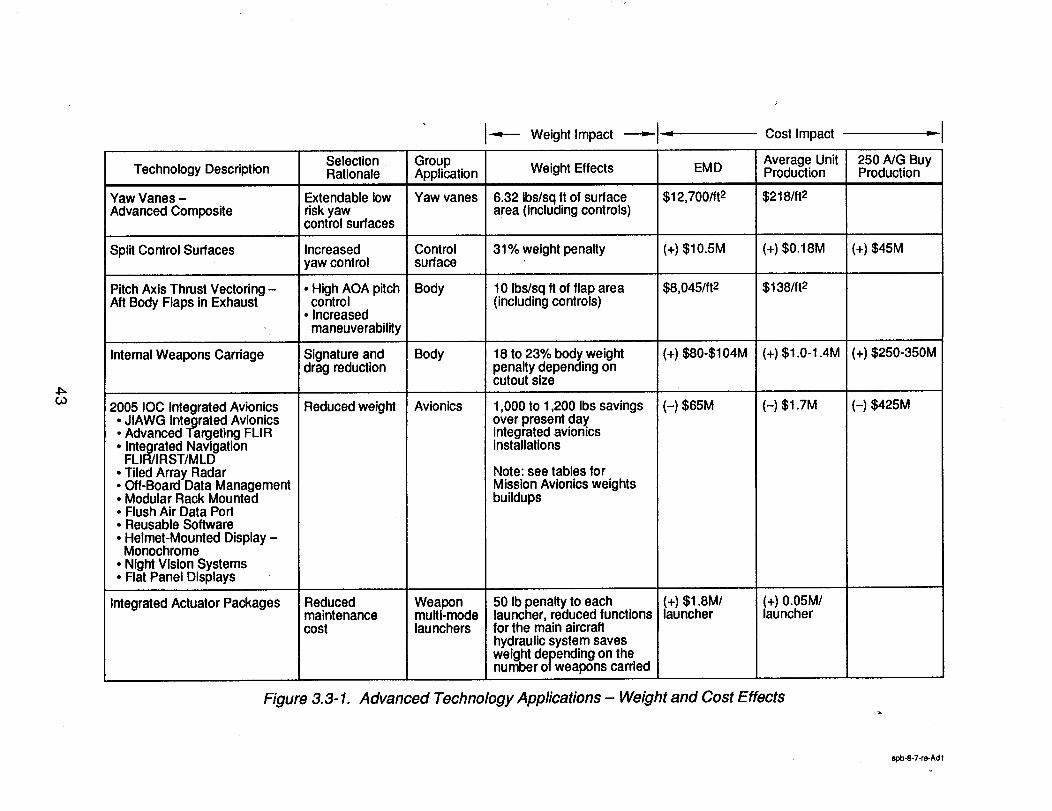
03
Technology Description
Yaw Vanes -Advanced Composite
Spilt Control Surfaces
PitchAxis Thrust Vectoring -Aft Body Flaps in Exhaust
Internal Weapons Carriage
2005 IOC Integrated Avionics
JIAWG Integrated AvionicsAdvanced Targeting FLIR• Integrated NavigationFLIR/IRST/MLD
• Tiled Array Radar• Off-Board Data Management• Modular Rack Mounted• Flush Air Data Port• Reusable Software• Helmet-Mounted Display-Monochrome
Night Vision SystemsFlat Panel Displays
Integrated Actuator Packages
SelectionRationale
Extendable lowriskyawcontrol surfaces
Increasedyaw control
• High AOA pitchcontrol
• Increasedmaneuverability
Signature anddrag reduction
Reduced weight
GroupApplication
Yaw vanes
Controlsurface
Body
Body
Avionics
---,,--- Weight Impact ----,-.-
Weight Effects
6.32 Ibs/sqft of surfacearea (includingcontrols)
31% weight penalty
10 Ibs/sq ft of flap area(includingcontrols)
18 to 23% body weightpenalty depending oncutout size
1,000 to 1,200 Ibssavingsover present dayintegrated avionicsinstallations
EMD
$12,700/ft 2
(+) $10.5M
$8,045/ft 2
(+) $80-$104M
(-) $65M
Cost Impact
Average UnitProduction
$218/ft 2
(+) $0.18M
$138/ft 2
(+)$1.0-I .4M
(-) $1.7M
B=,
250NG BuyProduction
(+) $45M
(+)$250-350M
(-) $425M
Note: see tables forMission Avionicsweightsbuildups
Reducedmaintenancecost
Weaponmulti-modelaunchers
50 Ib penalty to eachlauncher, reduced functionsforthe main aircrafthydraulicsystem savesweight depending on thenumber of weapons carried
(+) $1.8M/launcher
(+) 0.05M/launcher
Figure 3.3-1. Advanced Technology Applications - Weight and Cost Effects
sp_8-7-re-Ad I
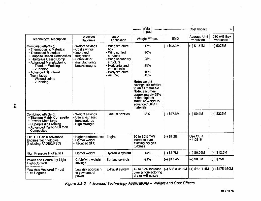
Cost Impact
Combined effects of:• Thermoplastic Materials• Thermoset Materials
Graphite Based CompositesFiberglass Based Comp.• Advanced Manufacturing
- Titanium Welding
.,,-.-- WeightImpact
Selection Group Average Unit 250 NG BuyTechnology Description Rationale Application Weight Effects Production Production
(-) $1.31 M (-) $327M
- Z Pinning• Advanced StructuralTechniques
- Welded Joints- Z Pinning
Combined effects of:• Titanium Matrix Composite• Powder Metallurgy
Superplastic FormingAdvanced Carbon-CarbonComposites
IHPTET Gen 6 AdvancedEngines Technologies(including FADEC/PSC)
High Pressure Hydraulics
Power and Control-by-LightFlight Controls
Weight savings: Cost savings• Improved
° toughnessPotential formanufacturingbreakrhroughs
: Weight savingsi Use at exhausttemperatures
• High strength
• Higher performanceLighter weightReduced SFC
Lighter weight
Cable/wire weightsavings
Low riskapproachto yaw controlpower
• Wing structuralbox
• Wing controlsurfaces
• Wing secondarystructure
• Horizontal and"vertical tails
• Body structure• Air inlet
Exhaust nozzles
Engine
Hydraulic system
Surface controls
Exhaust system
-17%
-20%
-22%
-25%
-12%-15%
Note: weightsavings are relativeto an all metal a/cNote: assumesapproximately 55%of the airplanestructure weight isadvanced GR/EPmaterials
35%
50 to 60% T/Wincrease overexistingdry gasturbines
-12%
-22%
EMD
(-) $92.3M
(-) $27.8M
(+) $1.2B
(-) $3.7M
(-) $17.4M
(+) $33.3-41.3MYaw Axis Vectored Thrust+ 45 Degrees
(-) $0.9M
Use CER* 1.0816
r
(-)$0.05M
(-) $0.3M
42 to 52% increaseover a nonvectoringdry or NB nozzle
(+) $1.1-1.4M
(-) $225M
(-) $12.5M
(-) $75M
(+) $275-350M
Figure 3.3-2. Advanced Technology Applications - Weight and Cost Effects
spb.8-7-re-Ad2
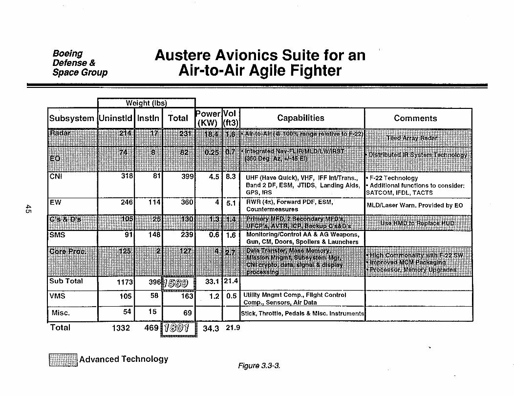
BoeingDefense &Space Group
Austere Avionics Suite for anA r-to-Air Agile Fighter
4_cn
Weic
Subsystem Uninstld Instln
CNI
EW
SMS
rll
I Sub Total
VMS
Misc.
318 81
Total
Total Capabilities Comments
..- ..........-.......:
::::::;;::::
iiiiiiii:82i!
399
105 58
54 15 69
1332 469 _/ 34.3
UHF (Have Quick), VHF, IFF Int/Trans.,
Band 2 DF, ESM, JTIDS, Landing Aids,GPS, IRS
RWR (4_), Forward PDF, ESM,Countermeasures
Monitoring/Control AA & AG Weapons,Gun, CM, Doors, Spoilers & Launchers
Utility Mngmt Comp., Flight ControlSensors. Air Data
Stick, Throttle, Pedals & Misc. Instrument_
21.9
F-22 TechnologyAdditional functions to consider:
;ATCOM, IFDL, TACTS
MLD/Laser Warn. Provided by EO
tiiiii!ii!iiiiii!iii!i.iii!!i_IAdvanced TechnologyFigure 3.3-3.
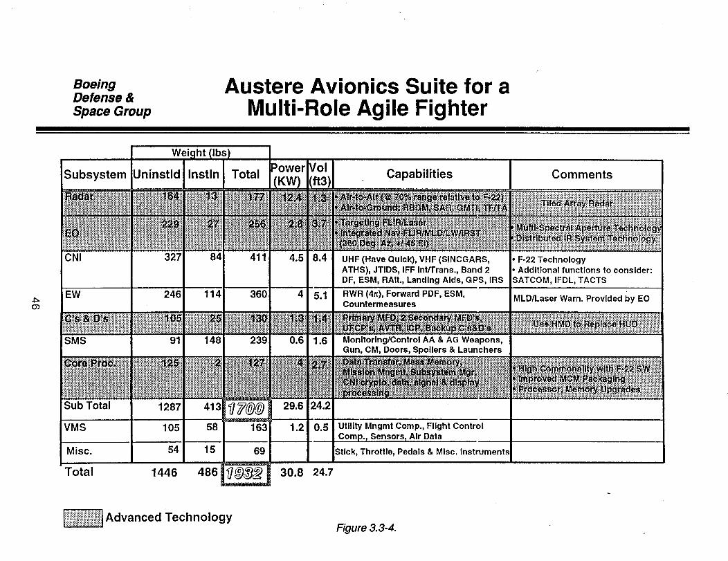
BoeingDefense &
Space Group
Austere Avionics Suite for aMulti-Role Agile Fighter
O3
Wei(
Subsystem Uninstld Instln Total
-...-.-.........
CNI 327 84 411
114 360EW 246
i_iiiiiiiiiii!SMS 91
JSub Total 1287 _@_
VMS 105 58 163
Misc. 54 15 69
Total 1446 486 _
148 239
........ Technology,_:_:_:_:_:_:_:z:_Advanced-=.:!:i:?:i:!:i:!:i:!:!:i:i:?:i:!:i:!:i:!:i:::::::::::::::::::::::::::::::::::::::::::
30.8 24.7
Capabilities
UHF (Have Quick), VHF (SINCGARS,ATHS), JTIDS, IFF Int/Trans., Band 2DF, ESM, RAIt., Landing Aids, GPS, IRS
RWR (4_), Forward PDF, ESM,Countermeasures
Monitoring/Control AA & AG Weapons,Gun, CM, Doors, Spoilers & Launchers
Utility Mngmt Comp., Flight ControlSensors t Air Data
SUck, Throttle, Pedals & Misc. Instruments
Figure 3.3-4.
Comments
F-22 TechnologyAdditional functions to consider:
;ATCOM, IFDL, TACTS
MLD/Laser Warn. Provided by EO
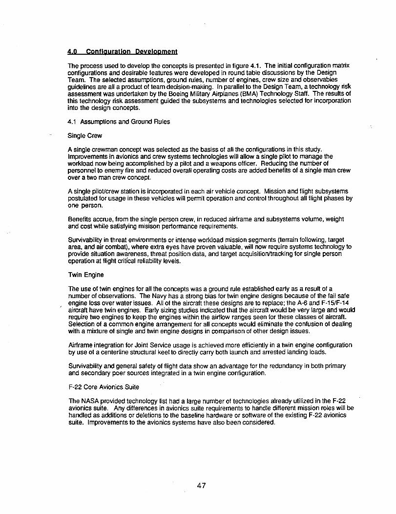
4,0 Configuration Development
The process used to develop the concepts is presented in figure 4.1. The initial configuration matrixconfigurations and desirable features were developed in round table discussions by the DesignTeam. The selected assumptions, ground rules, number of engines, crew size and observablesguidelines are all a product of team decision-making. In parallel to the Design Team, a technology riskassessment was undertaken by the Boeing Military Airplanes (BMA) Technology Staff. The results ofthis technology risk assessment guided the subsystems and technologies selected for incorporationinto the design concepts.
4.1 Assumptions and Ground Rules
Single Crew
A single crewman concept was selected as the basiss of all the configurations in this study.Improvements in avionics and crew systems technologies will allow a single pilot to manage theworkload now being accomplished by a pilot and a weapons officer. Reducing the number ofpersonnel to enemy fire and reduced overall operating costs are added benefits of a single man crewover a two man crew concept.
A single pilot/crew station is incorporated in each air vehicle concept. Mission and flightsubsystemspostulated for usage in these vehicles will permit operation and control throughout all flight phases byone person.
Benefits accrue, from the single person crew, in reduced airframe and subsystems volume, weightand cost while satisfying misison performance requirements.
Survivability in threat environments or intense workload mission segments (terrain following, targetarea, and air combat), where extra eyes have proven valuable, will now require systems technologytoprovide situation awareness, threat positiondata, and target acquisition/trackingfor single personoperation at flightcriticalreliability levels.
Twin Engine
The use of twin enginesfor all the concepts was a ground rule established early as a result of anumber of observations. The Navy has a strongbias for twin engine designs because of the fail safeengine lossover water issues. All of the aircraft these designs are to replace; the A-6 and F-15/F-14aircraft have twin engines. Early sizing studies indicated that the aircraft would be very large and wouldrequire two engines to keep the engines within the airflow ranges seen for these classes of aircraft.Selection of a common engine arrangement for all concepts would eliminate the confusion of dealingwith a mixture of single and twin engine designs in comparison of other design issues.
Airframe integration for Joint Service usage is achieved more efficientlyin a twin engine configurationby use of a centerline structural keel to directly carry both launch and arrested landing loads.
Survivability and general safety of flightdata show an advantage for the redundancy in both primaryand secondary poer sources integrated in a twin engine configuration.
F-22 Core Avionics Suite
The NASA provided technology list had a large number of technologies already utilized in the F-22avionics suite. Any differences in avionics suite requirements to handle different mission roles will behandled as additions or deletions to the baseline hardware or software of the existing F-22 avionicssuite. Improvements to the avionics systems have also been considered.
47
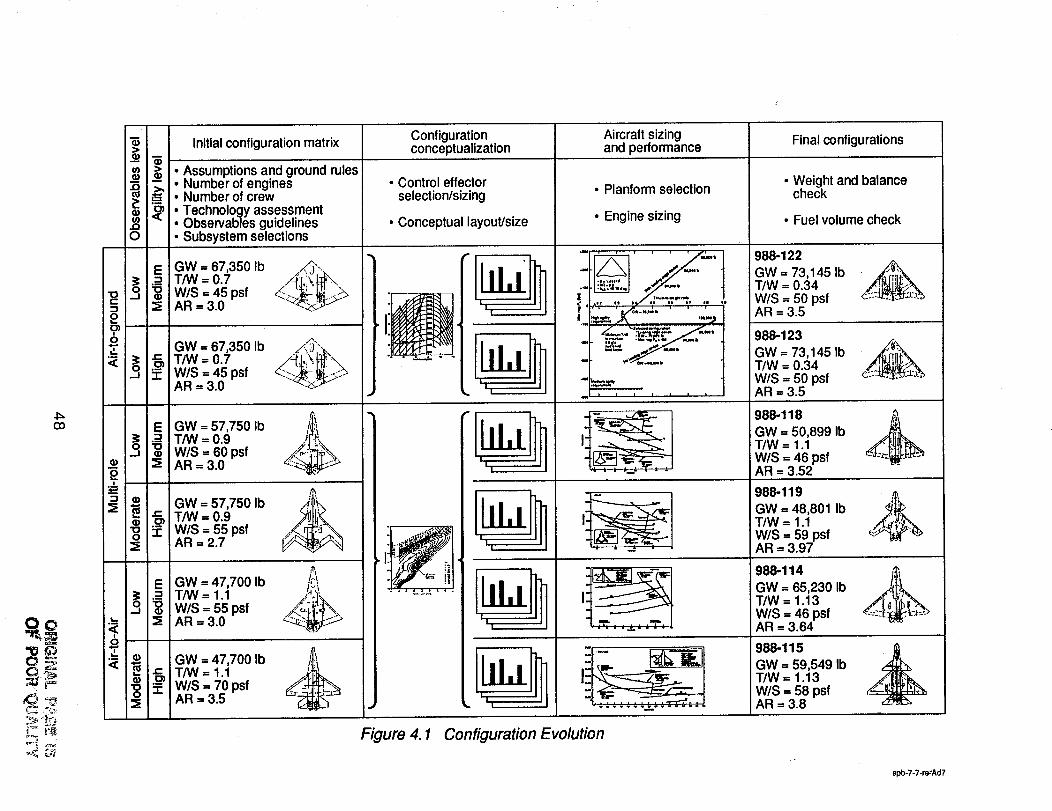
configuration Aircraftsizing Final configurationsconceptualization and performance
O: -9
Initialconfiguration matrix
--_ _ - Assumptions and ground rules
.._ ! Number of engines
= Number of crew_Technology assessmentObservables guidelinesO • Subsystem selections
GW = 67,350 Ib ,_\
T/W = 0.7 /-[_!i\ _w/s 45psf,--I =AR = 3.0 --
GW = 67,350 Ib_ _ T/W = 0.7
_: W/S 45psfAR = 3.0
T/W = 0.9 _%_o E W/S 60psf ._,,..- %AR =3.0 :_
GW = 57,750 Ib 4'_,%
_ T/W = 0.9 _h= W/S = 55 psf _ :,_:_,AR= 2.7 v-._/_.
GW = 47,700 Ib ]_/,',!;o T/W = 1.1 _._,,1._W/S = 55 psfAR = 3.0
GW = 47,700 Ib j__'._T/W = 1.1W/S -- 70 psfAR = 3.5
• Control effectorselection/sizing
• Conceptual layout/size
_ "'"
i II
II
_,. I
;i
II I
• Planform selection
• Engine sizing
. , , , , , ,
_,6,,,qCq,
I
!iI
i
• . . .,...# = ° °
u_ i
I'_i.
. . = = =,.=,. ....
• Weight and balancecheck
• Fuel volume check
988-122GW = 73,145 Ib _"..T/W = 0.34 _'_-W/S = 50 psf ::_AR = 3.5
988-123GW = 73,145 Ib _"
W/S = 50 psf ' "-AR = 3.5
GW = 50,899 IbT/W = 1.1W/S = 46 psfAR = 3.52
988-119 i,,'._.GW = 48,801 Ib _,.,,,T/W = 1.1W/S = 59 psfAR = 3.97
,8.,,T/W = 1.13W/S = 46 psfAR = 3.64
988-115 j_GW = 59,549 IbT/W = 1.13W/S = 58 psfAR = 3.8
Figure 4.1 Configuration Evolution
$pb-7-7-re_Ad7
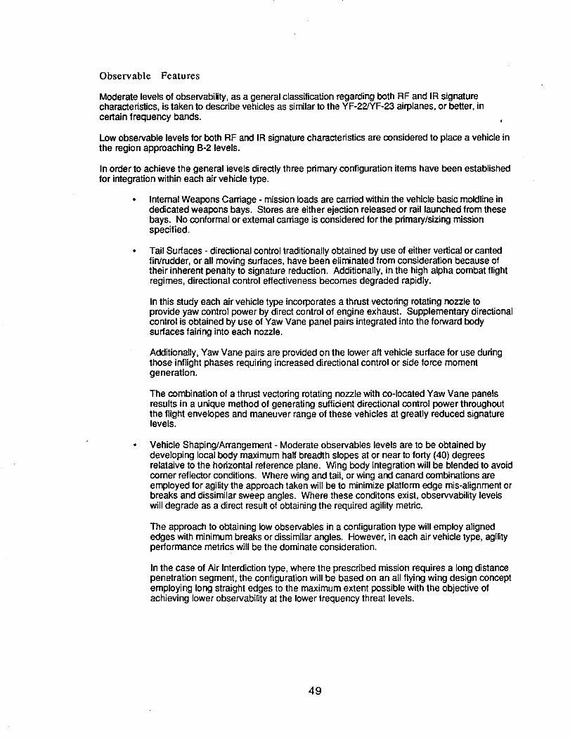
Observable Features
Moderate levels of observability,as a general classificationregarding both RF and IR signaturecharacteristics, is taken to describe vehicles as similarto the YF-22/YF-23 airplanes, or better, incertain frequency bands.
Lowobservable levels for both RF and IR signature characteristics are considered to place a vehicle inthe region approaching B-2 levels.
In order to achieve the general levels directlythree primary configuration items have been establishedfor integration within each air vehicle type.
Internal Weapons Carriage - mission loads are carded within the vehicle basic moldlineindedicated weapons bays. Stores are either ejection released or rail launched from thesebays. No conformal or external carriage is considered for the primary/sizing missionspecified.
Tail Surfaces - directional control traditionallyobtained by use of either vertical or cantedfin/rudder, or all moving surfaces, have been eliminated from consideration because oftheir inherent penalty to signature reduction. Additionally, in the high alpha combat flightregimes, directional control effectiveness becomes degraded rapidly.
Inthis study each air vehicle type incorporates a thrust vectoring rotating nozzle toprovide yaw control power by direct control of engine exhaust. Supplementary directionalcontrol is obtained by use of Yaw Vane panel pairs integrated into the forward bodysurfaces fairing into each nozzle.
Additionally, Yaw Vane pairs are provided on the lower aft vehicle surface for use duringthose inflight phases requiring increased directional control or side force momentgeneration.
The combination of a thrust vectoring rotating nozzle with co-located Yaw Vane panelsresults in a unique method of generating sufficient directional control power throughoutthe flight envelopes and maneuver range of these vehicles at greatly reduced signaturelevels.
Vehicle Shaping/Arrangement - Moderate observables levels are to be obtained bydeveloping local body maximum half breadth slopes at or near to forty (40) degreesrelataive to the horizontal reference plane. Wing body integration will be blended to avoidcorner reflector conditions. Where wing and tail, or wing and canard combinations areemployed for agility the approach taken will be to minimize platform edge mis-alignment orbreaks and dissimilar sweep angles. Where these conditons exist, observvability levelswill degrade as a direct result of obtaining the required agility metric.
The approach to obtaining low observables in a configuration type will employ alignededges with minimum breaks or dissimilar angles. However, in each air vehicle type, agilityperformance metrics will be the dominate consideration.
In the case of Air Interdiction type, where the prescribed mission requires a longdistancepenetration segment, the configuration will be based on an all flying wing design conceptemploying long straight edges to the maximum extent possible with the objective ofachieving lower observability at the lower frequency threat levels.
49
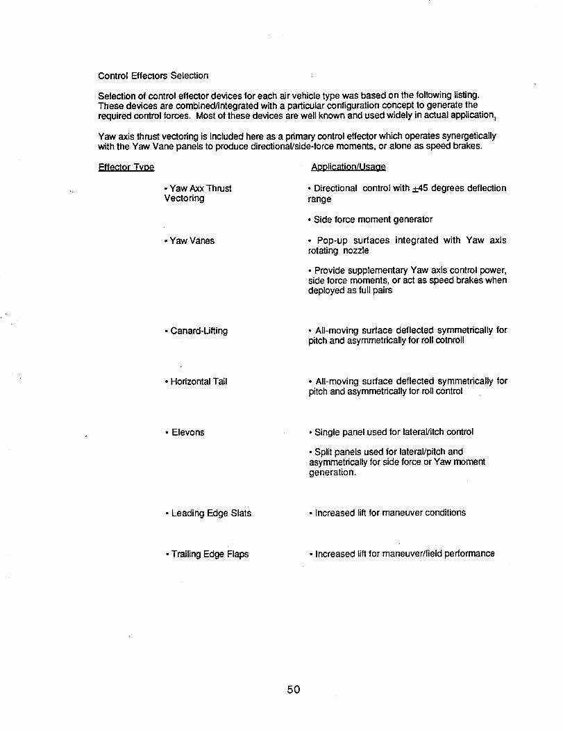
ControlEffectors Selection
Selection of control effector devices for each air vehicle type was based on the following listing.These devices are combined/integrated with a particularconfiguration concept to generate therequired control forces. Most of these devices are well known and used widely in actual application;
Yaw axis thrust vectoring is included here as a primary control effectorwhich operates synergeticallywith the Yaw Vane panels to produce directional/side-force moments, or alone as speed brakes.
• Yaw Axx ThrustVectoring
• Yaw Vanes
AoolicationlUsage
•Directionalcontrolwith._+45degreesdeflection
range
•Sideforcemoment generator
• Pop-up surfaces integratedwith Yaw axisrotatingnozzle
•ProvidesupplementaryYaw axiscontrolpower,sideforcemoments, oractas speed brakeswhendeployedas fullpairs
• Canard-Lifting • All-moving surface deflected symmetrically forpitch and asymmetrically for roll cotnroll
• Horizontal Tail • All-moving surface deflected symmetrically forpitch and asymmetrically for roll control
• Elevons • Single panel used for lateral/itch control
• Split panels used for lateral/pitch andasymmetrically for side force or Yaw momentgeneration.
• Leading Edge Slats • Increased lift for maneuver conditions
• Trailing Edge Flaps •Increased liftfor maneuver/field performance
50
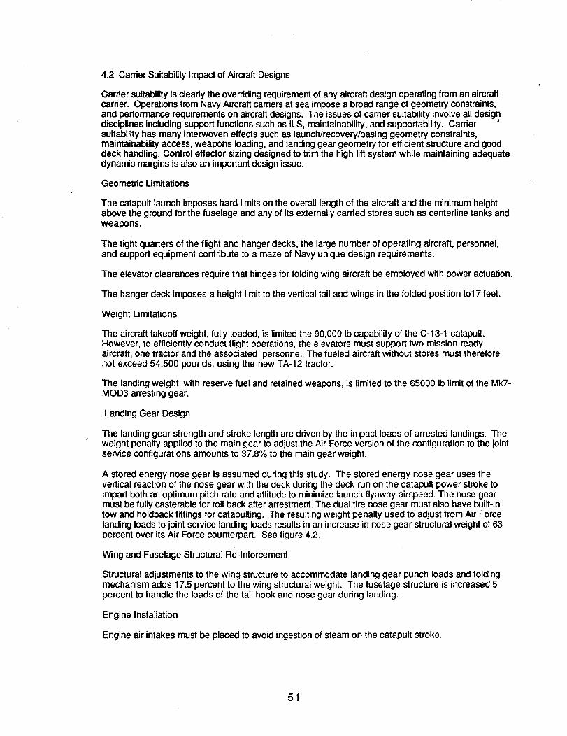
4.2 Carder Suitability Impact of AircraftDesigns
Carder suitabilityis clearly the overdding requirement of any aircraft design operating from an aircraftcarrier. Operations from Navy Aircraftcarders at sea impose a broad range of geometry constraints,and performance requirements on aircraft designs. The issues of carder suitability involve all designdisciplinesincluding support functions such as ILS, maintainability, and supportability. Cardersuitabilityhas many interwoven effects such as launch/recovery/basing geometry constraints,maintainability access, weapons loading, and landing gear geometry for efficient structureand gooddeck handling. Control effector sizing designed to trim the high liftsystem while maintaining adequatedynamic margins is also an important design issue.
Geometric Umitations
The catapult launch imposes hard limitson the overall length of the aircraft and the minimum heightabove the ground for the fuselage and any of its externally carded stores such as centerline tanks andweapons.
The tight quarters of the flight and hanger decks, the large number of operating aircraft, personnel,and support equipment contribute to a maze of Navy unique design requirements.
The elevator clearances require that hinges for folding wing aircraft be employed with power actuation.
The hanger deck imposes a height limit to the vertical tail and wings in the folded position to17 feet.
Weight Limitations
The aircraft takeoff weight, fully loaded, is limited the 90,000 Ib capability of the C-13-1 catapult.However, to efficiently conduct flight operations, the elevators must support two mission readyaircraft, one tractor and the associated personnel. The fueled aircraft without stores must thereforenot exceed 54,500 pounds, using the new TA-12 tractor.
The landingweight, with reserve fuel and retained weapons, is limitedto the 65000 Ib limit of the Mk7-MOD3 arresting gear.
Landing Gear Design
The landing gear strength and stroke length are driven by the impact loads of arrested landings. Theweight penalty applied to the main gear to adjust the Air Force version of the configuration to the jointservice configurations amounts to 37.8% to the main gear weight.
A stored energy nose gear is assumed during this study. The stored energy nose gear uses thevertical reaction of the nose gear with the deck during the deck run on the catapult power stroke toimpart both an optimum pitch rate and attitude to minimize launch flyaway airspeed. The nose gearmust be fully casterable for roll back after arrestment. The dual tire nose gear must also have built-intow and holdback fittings for catapulting. The resulting weight penalty used to adjust from Air Forcelanding loads to joint service landing loads results in an increase in nose gear structural weight of 63percent over its Air Force counterpart. See figure 4.2.
Wing and Fuselage Structural Re-lnforcement
Structural adjustments to the wing structure to accommodate landing gear punch loads and foldingmechanism adds 17.5 percent to the wing structural weight. The fuselage structure is increased 5percent to handle the loads of the tail hook and nose gear during landing.
Engine Installation
Engine air intakes must be placed to avoid ingestionof steam on the catapult stroke.
51
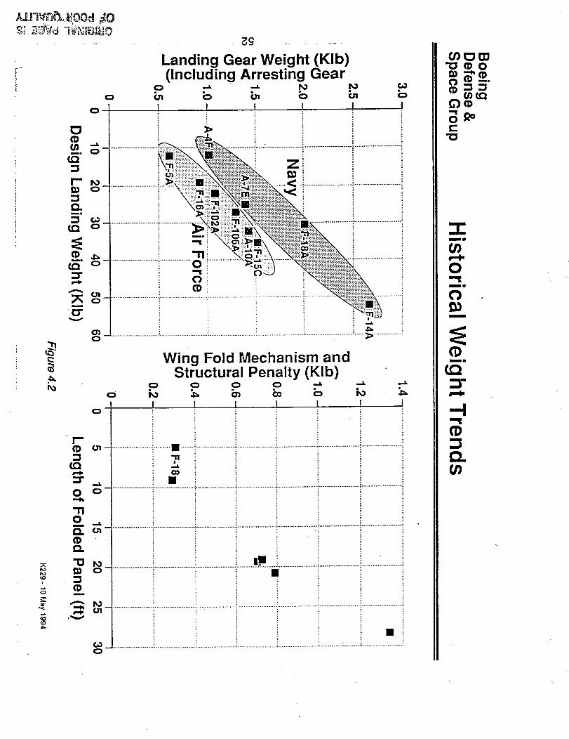
L
0
0
0
ro
¢o
o
_S
Landing Gear Weight (Klb)(Including Arresting Gear
e=o
I
Z
I-"(I)
O
"1"iOm
¢2.CD
"O
¢Dm
==dl.
Wing Fold Mechanism andStructural Penalty (KIb)
!
.............................................. : ...................... i
0_
.............................................. _.................... ..................................... _..o.= ........................... ; ...................... <
o []
¢D e,n¢_
8,=e-
"ID
"-r"Nil
=,,=i=
Omil
O
¢D
:3"
---I¢D
¢2.t_
Engines must be located to allow complete removal and replacement without cranes, while wings arefolded, in the hanger deck area.
Weapons Loading
Weapons must be loaded while wings are folded, withoutthe use of cranes or ladders.Suspended weapons must be high enough above the ground to clear the catapult shuttle and toavoid deck impact in a wing-low arrested landing.
High Uft Devices
The wing designs used have historicallyused highlift flap systems and other devices to allow safe lowspeed flight after catapult release, fully loaded.
The wing must also provide low lift for safe go around without touchdown on an aborted landing.
Support Equipment
Steps or ladders for entry of the crew must be built-into minimize deck clutter safety hazards on theflight deck and the hanger deck.
Fueling and routine servicing or rearming must not require platformsor external hoists,only dollies.
Environment
High sea-states and low-visibility/nightoperations demand an aircraft with superior stability and controlcharacteristics to accomplish the required high recision flight path control necessary to routinelyaccomplish recovery safely.
Landing Recovery
Carrier approach speed, approach angle-of-attack, stall margin, vision angle, pop-up maneuver,longitudinalacceleration, thrust response, single engine rate-of-climb analysis are all inherent analysiscapabilitywithin the Fighter Aircraft Sizing Tool (FAST) aircraft sizing and performance code. Thecarder suitabilityanalysis modules in FAST parallel the conceptual level methodology of the NAVAIRCAT and APR codes. In addition, FAST is capable of determining a rough order estimate of carrierspotting factor.
The main driver in carrier recovery is the requirement for significantlylower airspeeds during approachand arrestment. This drives the designer to maximize the use of high lift recovery devices. Use ofsuch devices frequently conflict with the need to use thinner, cleaner airfoils optimized for high-speedup and away flight. Safe recovery of Navy aircraft force the design to emphasize low speed stabilityand Control regions driving the size of the horizontal surface up. Naval aircraft become a balancebetween the uncompromising need for safe flying qualities at the low speed end of the flightenvelope while minimize_ng maneuvering and performance penalties at the high speed end.
Catapult Launch
Catapult launch analysis determines the minimum safe launch airspeeds while maintaining acceptableflight characteristics in this low altitude, high angle-of-attack regime. Approach and landing requiresthe slowest possible approach airspeeds while retaining the performance and handling qualities needfor precision glide slope control. Keeping approach airspeeds low results in reduced ship's operatingspeed and thus enhances the operational flexibility of the aircraft carder.
Catapult launch presents the danger of operating too close to the aircraft minimum control airspeed.Since catapult end-speed is constrained by catapult performance, the requirement for a 10% stallmargin at the end of the deck-run and an angle-of-attack margin 20% below stall drives the designer tomaximize Clmax in the takeoff configuration. The requirement of a 500 foot/minute minimum rate of
53
climb inthe event of an engine failure and a fly-away longitudinalacceleration greater than 0.065 gsimply the need to maximize L/D beyond that required for an equivalent Air Force Aircraft.
The naval aviator has to be able to see the carder during approach at relatively high angle-of-attack.The location of the pilots eye and shape of the aircraft nose must accommodate this approach angle-of-attack. A 3.5 degree glideslope mandates an 18. degree over-the-nose vision angle for carrierapproach.
Wave-off and Bolter
Wave-off and bolter present further constraints on the propulsion and drag-brake systems, which inturn directly affect stabilityand control through rapidly occurring, transient changes accompanyingtypically large thrust commands. The major challenge is obtaining quick engine response, coupledwith an adequate amount of pitch control.
Combat Maneuvering
Up-and-away maneuvering requirements have traditionally been more stringent for the Navy becauseof its insistence of utilizing as much of the flight envelope originally designed into the aircraft. TheNavy expects their pilots to fly to the edge of the envelope and consequently drives the designer toprovide Level 1 flying qualities to the maximum limits of the operational envelope. This has a numberof implications to departure resistance, angle-of-attack limiters, and maneuver devices.
The Navy requires high departure resistance at highangle-of-attack sufficient to prevent Ioss-o controlwhile maneuvering close to and possibly through the flight envelope where aerodynamic controltraditionallybeginsto diminish. The Air Force will typically accept limitersto avoid approaching CLmaxboundaries throughout the maneuvering envelope. The Air Force F-16 employes an angle-of-attacklimitingschedule which shrinks the left boundary of the energy maneuverability envelope significantlybeyond comer speed. Unique maneuver devices normally found on naval aircraft to ensure maximummaneuvering performance over a full flight envelope. These devices usuallytake advantage of analready unique low speed, high lift system such as the maneuver flap or slat.
54
4.3 Designing for Agility
This section discusses studies conducted to relate the agility metrics to design considerations (figure4.3-1). Before the design studies could be carded out, a framework of design guidelines wasestablished. Aerodynamic characteristic needs were derived from the metrics and the designguidelines. Techniques were formulated to bridge the gap between metrics/guidelines and effect'orsizing. Finally, this approach was used to size effectors on three different airplane configurations: onemedium agility and ten high-agility concepts.
Agility metrics are defined in figure 4.3-1 below. The agility performance of conceptual configurationsis discussed in terms of aerodynamic forces and moments required to meet these performance goals.
4.3.1 Agility Metrics
Maximum Negative Specific Excess Power
Maximum negative specific excess power (Ps) is a metric that was created to describe the energy lossof an aircraft while executing an unsteady turn. This metric attempts to quantify an aircraft's potentialfor losing energy by measuring the minimum (or maximum negative) PS (rate of change in specificenergy) achieved during a maneuver. Maximum negative specific excess power corresponds to anaircraft's maximum instantaneous turn rate capability
Energy exchange during combat is a combination of speed loss (kinetic energy) and/or altitude loss(potential energy) and depends on the controls applied by the pilot or flight control system and theaircraft's aerodynamic characteristics. The classical approach to combat management is to minimizeenergy loss during combat.
Maneuver employed to attain the maximum instantaneous turn rate consists of using the elevator toincrease the aircraft angle-of-attack and, in some cases, the application of aileron, rudder, speedbrakes, and maneuyer flaps. Although a reduction of thrust would result in a reduction of the net axialforce on the aircraft (and thus a reduction of specific excess power) this technique is not normallyused. Engine response time is of the same order of magnitude as the time needed to achieve thedesired conditions. Furthermore, the capability to gain speed following the turn would be seriouslycompromised.
Computation of the maximum negative specific excess power is identical to specific excess powerperformance. This is addressed in section 5.0 along with the maneuver performance requirements..
Time-to-Bank and Capture 90-Degrees
In air combat, the offensive pilot attempts to achieve target acquisition. To achieve his objective ofdestroying the enemy, the pilot must successfully deploy his weapon, which requires aiming orlocking-on. To lock-on or aim a weapon the pilot must precisely control his aircraft. During this phase,the defensive pilot tries to evade the offensive pilot's attempt by jinking of-of-plane and changing thebattle geometry. The offensive pilot has to reacquire the target and track sufficiently to deploy hisweapon. The cycle of acquire, jink, reacquire, jink, etc., is characterized by the offensive pilot'sbanking with the intent of capturing a specific bank angle as determined by the jinking maneuver ofthe defensive participant. Time-to-bank to and capture 90 -degrees was chosen as an agility metricbecause it quantifies an aircraft's ability to offensively reacquire an evading target.
Airplane roll performance is measured with respect to a single-degree-of-freedom system. While thepilot may use the rudder peddles to slip the airplane and increase roll acceleration, the designer is notpermitted to take advantage of this maneuver. Indeed, for a class IV airplane, automatic turncoordination is already required, insuring that the airplane behaves as a single-degree-of-freedomsystem in roll. Therefore, the performance of the roll control system can, to a great extent, bedescribed by two terms: maximum roll acceleration and the roll time constant. Maximum rollacceleration is proportional to the roll control moment available. Roll time constant is related to theairplane roll damping. Roll damping can be influenced by roll rate feedback if required. Much research
55
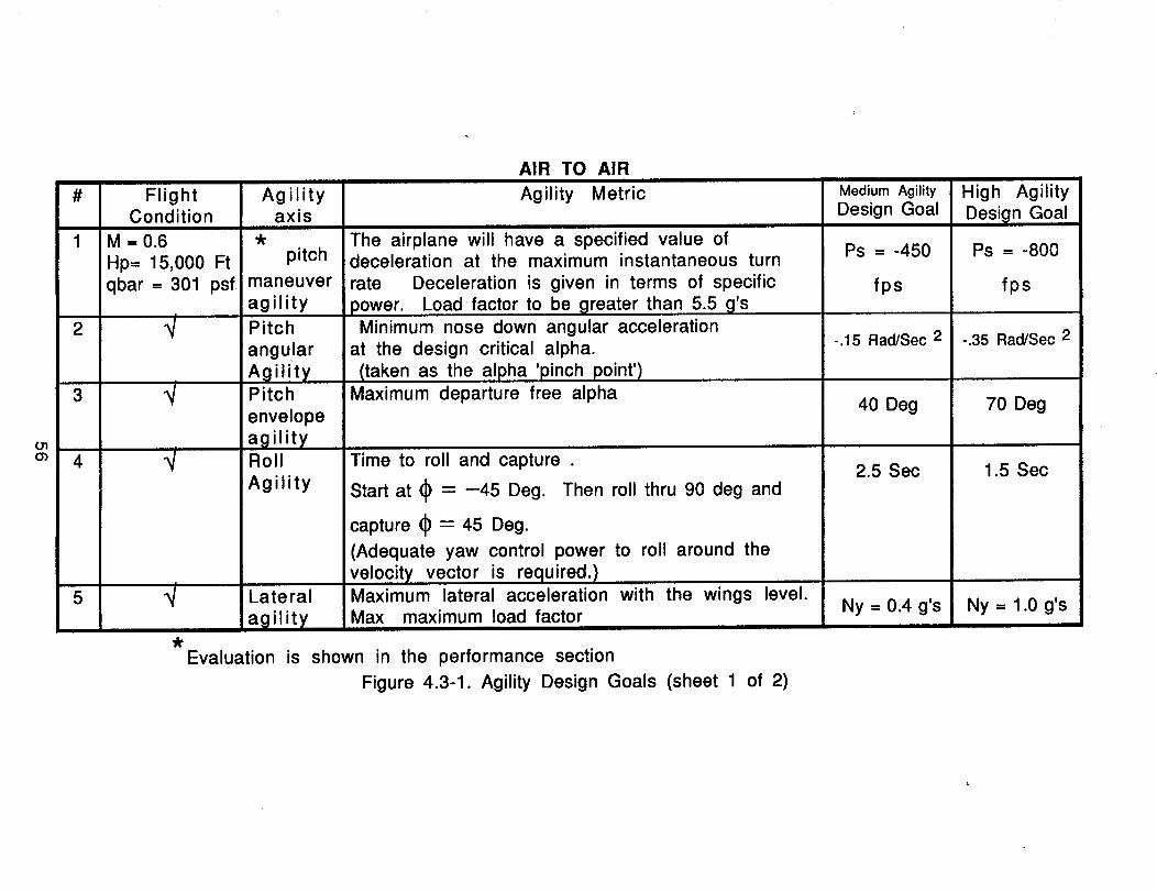
# Flight AgilityCondition axis
1 M = 0.6
Hp= 15,000 Ft pitch
qbar = 301 psf maneuveragility
2 _t Pitch
angular
Agility
3 "_ Pitch
envelope
agility4 _t Roll
Agility
5 _t Lateral
agility
_t
AIR TO AIR
Agility Metric
The airplane will have a specified value ofdeceleration at the maximum instantaneous turn
rate Deceleration is given in terms of specific
power. Load factor to be greater than 5.5 g'sMinimum nose down angular acceleration
at the design critical alpha.
(taken as the alpha 'pinch point')Maximum departure free alpha
Time to roll and capture .
Start at _ = -45 Deg. Then roll thru 90 deg and
capture _ -- 45 Deg.
(Adequate yaw control power to roll around the
velocity vector is required.)Maximum lateral acceleration with the wings level.Max maximum load factor
Evaluation is shown in the performance section
Figure 4.3-1. Agility Design Goals (sheet 1 of 2)
Medium AgilityDesign Goal
Ps = -450
fps
-.15 Rad/Sec 2
40 Deg
2.5 Sec
Ny = 0.4 g's
High Agility
Desi_In Goal
Ps = -800
fps
-.35 Rad/Sec 2
70 Deg
1.5 Sec
Ny = 1.0 g's
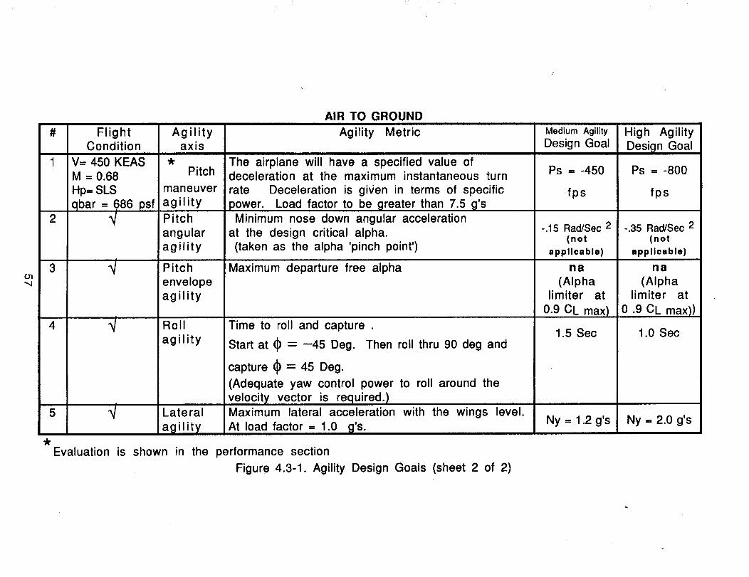
O1
# Flight AgilityCondition axis
V= 450 KEASM = 0.68 Pitch
Hp= SLS maneuver
qbar = 686 psf agility2 _ Pitch
angular
agility
3 _t Pitch
envelope
agility
AIR TO GROUND
Agility Metric
The airplane will have a specified value ofdeceleration at the maximum instantaneous turn
rate Deceleration is gi_/en in terms of specific
power. Load factor to be greater than 7.5 g's
Minimum nose down angular acceleration
at the design critical alpha.
(taken as the alpha 'pinch point')
Maximum departure free alpha
4 _t Roll Time to roll and capture .
agility
5 _t Lateral
agility_t
Start at _ = --45 Deg. Then roll thru 90 deg and
capture (_ -- 45 Deg.
(Adequate yaw control power to roll around the
velocity vector is required.)Maximum lateral acceleration with the wings level.
At load factor = 1.0 g's.
Evaluation is shown in the performance section
Figure 4.3-1. Agility Design Goals (sheet 2 of 2)
Medium Agility
Design Goal
Ps = -450
fps
-.15 Rad/Sec 2(not
applicable)
na
(Alphalimiter at
0.9 CL max)
1.5 Sec
Ny = 1.2 g's
High Agility
Desi_ln Goal
Ps = -800
fps
-.35 Rad/Sec 2(not
applicable)
na
(Alphalimiter at
0.9 CL max))
1.0 Sec
Ny = 2.0 g's
has been done to determine optimum values for roll acceleration requirements and time constants.Specifying a minimum rollacceleration capability and time constant, along with a control rate input,results in a unique rollangle time history. Frequently, specificationsare expressed as the timerequiredto roll througha certain rollangle. For a class IV airplane at combat flightconditions, this isusually 90 degrees in 1 second. It is the task of the preliminary design engineer to ensure enough rollcontrol to meet this specification. Adequate roll control must be designed into the airplane during'preliminary design. The designer has some control over the time constant through roll rate feedback.
Maximum Nose-Down Pitch Acceleration
Many times in air combat the roles of the offensive and defensive pilotsare reversed. When anoffensive pilot is faced with role reversal his objective changes from that of destroying the enemy tonot being destroyed. A frequently successful defensive tactic is to disengage, break off the battle,and retum to safe air space. As the defensive pilotattempts this action, the offensive pilotwillcontinue his pursuit. The success of the defensive pilot depends on his ability to transition from anengagement mode characterized by high load factors and highturn rates to an escape modecharacterized by high longitudinalaccelerations to maximize the separation distance. This maneuverrequires the pilot to unload his airplane as quickly as possible and achieve a minimum drag flightangle-of-attack. Maximum nose-down pitch acceleration was chosen as an agility metric to quantify theaircraft's transition from a highly loaded air combat flight condition to an escape or maximumlongitudinal acceleration condition.
Maximum Achievable Trimmed Angle-of-Attack
Modem air combat research has shown that high angle-of-attack or post-stall flight may provide atactical advantage on both offensive and defensive aerial engagements. In an offensive mode thepilot's abilityto turn at higher turn rates with smaller turn radii provides him with the optionto morequickly achieve shot opportunity by out-maneuvering his opponent. In a defensive mode high-angle-of-attack capability can be utilized by a pilot to bleed energy more quickly, thus forcing the offensivepilot to overshoot and providingrole reversal. In either case high-angle-of-attack capability will beutilized by a pilot ohly if the airplane remains controllable and has good handling qualities. MaximumAchievable (Departure-Free) Trimmed Angle-of-Attack was chosen as an agility metricto quanti_j anaircraft's abilityto utilize the post-stall flight regime.
Maximum Lateral Acceleration
It has been proposedthat an aircraft's abilityto laterally translate its position may be of significanttactical advantage. In a real engagement this ability may provide useful defensively as a jinkingmaneuver. However, this characteristic may be of even greater importance in a ground attack mode.Typically, highvalue ground targets are attacked in a manner requiringa single pass or flyby for eachtarget. An airplane with substantial lateral displacement capabilitymay be able to attack a target,laterallydisplace its position, acquire and attack a second target on the same pass. Maximum lateralacceleration was chosen as an agilitymetric to quantify an airplane's abilityto attack multiple groundtargets on a single pass.
Before discussing the scope analysis a few words must be said about how the agility is used and itsimportance. Tactics using flat turns were flight tested by the USAF in 1983 on the AFTI/F-16. Therecommendations from that testing (more than 15 unique flight modes were tactically tested) singledout flat turns as important for new airplanes.
The maneuver was best for a/g and not as good for a/a. It was best for strafing runs and deliveringdumb bombs. Delivery of smart bombs may not be an agility issue. The same is true for a/a. The flatturn would be best for a/a gunnery and not guided a/a missiles.
Flat turns made the airplane more lethal and at the same time more survivable. The use of flat tums iscomplex. For example, the optimum dumb bombing technique combined classical rolland pitch forgross heading changes with flat turn for small changes. The pilot used rollstick to quicklyget thepipper in the vicinityof the target. Remaining directional errors were removed with flat run rudder
58
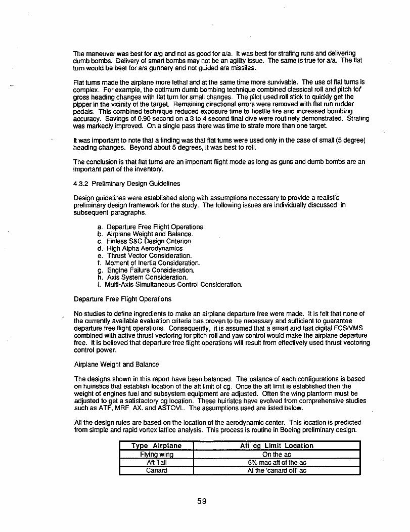
Themaneuverwasbestfora/gandnotasgoodfora/a. Itwasbestforstrafingrunsanddeliveringdumbbombs.Deliveryofsmartbombs may notbe an agilityissue. The same is true for a/a. The flattum would be best for a/a gunnery and notguided a/a missiles.
Flat tums made the airplane more lethal and at the same time more survivable. The use of flat turns iscomplex. For example, the optimum dumb bombingtechnique combined classical roll and pitch forgross heading changes with flat turn for small changes• The pilotused roll stick to quickly get thepipper in the vicinityof the target. Remaining directional errorswere removed with flat run rudderpedals. This combined technique reduced exposure time to hostile fire and increased bombingaccuracy. Savings of 0.90 second on a 3 to 4 second final dive were routinelydemonstrated. Strafingwas markedly improved. On a single pass there was time to strafe more than one target•
It was importantto note that a finding was that flat tums were used only in the case of small (5 degree)heading changes. Beyond about 5 degrees, it was best to roll.
The conclusion is that flat turns are an importantflight mode as long as guns and dumb bombs are animportant part of the inventory.
4.3.2 Preliminary Design Guidelines
Design guidelines were established along with assumptions necessary to provide a realzst=cpreliminary design framework for the study. The following issues are individually discussed insubsequent paragraphs.
a. Departure Free Flight Operations.b. Airplane Weight and Balance.c. Finless S&C Design Criteriond. High Alpha Aerodynamicse. Thrust Vector Consideration.f. Moment of Inertia Consideration.g. Engine I_ailure Consideration.h. Axis System Consideration.i. Multi-Axis Simultaneous Control Consideration.
Departure Free Flight Operations
No studies to define ingredients to make an airplane departure free were made. It is felt that none ofthe currently available evaluation criteria has proven to be necessary and sufficient to guaranteedeparture free flight operations. Consequently, it is assumed that a smart and fast digital FCSNMScombined with active thrust vectoring for pitch roll and yaw control would make the airplane departurefree. It is believed that departure free flight operations will result from effectively used thrust vectoringcontrol power.
Airplane Weight and Balance
The designs shown in this report have been balanced. The balance of each configurations is basedon huiristics that establish location of the aft limit of cg. Once the aft limit is established then theweight of engines fuel and subsystem equipment are adjusted. Often the wing planform must beadjusted to get a satisfactory cg location. These huiristcs have evolved from comprehensive studiessuch as ATF, MRF AX. and ASTOVL. The assumptions used are listed below.
All the design rules are based on the location of the aerodynamic center. This location is predictedfrom simple and rapid vortex lattice analysis. This process is routine in Boeing preliminary design.
Type Airplane Aft cg Limit LocationFlying wing On the ac
Aft Tail 5% mac aft of the acCanard At the 'canard off' ac
59
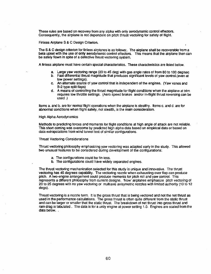
These rules are based on recovery from any alpha with only aerodynamic control effectors.Consequently, the airplane is not dependent on pitch thrust vectoring for safety of flight.
Finless Airplane S & C Design Criterion.
The S & C design criterionforfinless airplanes is as follows:. The airplane shall be recoverable from abeta upset with the use of only aerodynamic control effectors. This means that the airplane then canbe safely flown in spite of a defective thrust vectoring system.
A finless airplane must have certain special characteristics. These characteristics are listed below.
a. Large yaw vectoring range (20 to 45 deg) with gas angle rates of from 80 to 100 deg/secb. Fast differential thrust magnitude that produces significant levels of yaw control.(even at
low power settings).Co An alternate source of yaw control that is independent of the engines. (Yaw vanes and
B-2 type split flaps)d. A means of controlling the thrust magnitude for flight conditionswhen the airplane at trim
requires low throttle settings. (Aero speed brakes and/or in-flight thrust reversing can beused .)
Items a. and b. are for normal flight operationswhen the airplane is stealthy. Items c. and d. are forabnormal conditions when flight safety, not stealth, is the main consideration.
High Alpha Aerodynamics
Methods to predicting forces and moments for flight conditions at high angle of attack are not reliable.This short coming was overcome by predicted high alpha data based on empirical data or based ondata extrapolations from wind tunnel test of similar configurations.
Thrust Vectoring Considerations
Thrust vectoring philosophy emphasizing yaw vectoring was adapted early in the study. This allowedtwo unusual features to be considered during development of the configurations:
a. The configurations could be fin-less.b. The configurations could have widely separated engines.
The thrust vectoring mechanization selected for this study is unique and innovative. The thrustvectoring has 45 degrees capability. The vectoring nozzle when exhausting over flap can producepitch. A two-engine arrangement could produce moments for pitch roll and yaw control. Thisrepresents a different philosophy from current designs. 'Now' airplanes emphasize pitch vectoring of20 to 25 degrees with no yaw vectoring or multiaxis axisymetric nozzles with limitedauthority (10 to 12degs).
Thrust vectoring is a nozzle term. It is the gross thrust that is being vectored and not the net thrust asused in the performance calculations. The gross thrust is often quite different from the static thrustand can be larger or smaller that the static thrust. The breakdown of net thrust into gross thrust andram drag is tabulated. The data is for a unity engine at power setting 1.0. Engines are scaled from thedata below..
60
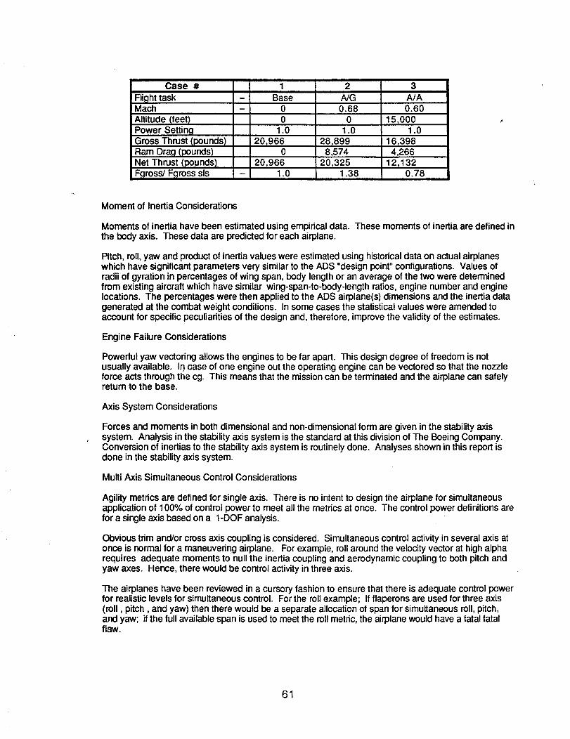
Case # 1 2 3
Flight task - Base A/G A/AMach - 0 0.68 0.60Altitude (feet) 0 0 15,000Power Setting 1.0 1.0 1.0Gross Thrust (pounds) 20r966 28,899 16,398Ram Drag (pounds) 0 8,574 4,266Net Thrust (pounds) 20,966 20,325 12,132Fgross/Fgross sis - 1.0 1.38 0.78
Moment of Inertia Considerations
Moments of inertia have been estimated using empirical data. These moments of inertia are defined inthe body axis. These data are predicted for each airplane.
Pitch, roll,yaw and product of inertia values were estimated using historical data on actual airplaneswhich have significantparameters very similarto the ADS "design point"configurations. Values ofradii of gyration in percentages of wing span, body lengthor an average of the two were determinedfrom existing aircraft which have similar wing-span-to-body-length ratios, engine number and enginelocations. The percentages were then applied to the ADS airplane(s) dimensions and the inertia datagenerated at the combat weight conditions. In some cases the statisticalvalues were amended toaccount for specific peculiarities of the design and, therefore, improve the validity of the estimates.
Engine Failure Considerations
Powerful yaw vectoring allows the engines to be far apart. This design degree of freedom is notusually available. In case of one engine out the operating engine can be vectored so that the nozzleforce acts through the cg. This means that the mission can be terminated and the airplane can safelyreturn to the base.
Axis System Considerations
Forces and moments in both dimensional and non-dimensional form are given in the stabilityaxissystem. Analysis in the stabilityaxis system is the standard at this divisionof The Boeing Company.Conversion of inertias to the stabilityaxis system is routinelydone. Analyses shown in this report isdone in the stabilityaxis system.
Multi Axis Simultaneous Control Considerations
Agility metrics are defined for single axis. There is no intent to design the airplane for simultaneousapplication of 100% of control power to meet all the metrics at once. The control power definitions arefor a single axis based on a 1-DOF analysis.
Obvious trim and/or cross axis coupling is considered. Simultaneous control activity in several axis atonce is normal for a maneuvering airplane. For example, rollaround the velocityvector at high alpharequires adequate moments to null the inertia coupling and aerodynamic coupling to both pitch andyaw axes. Hence, there would be control activityin three axis.
The airplanes have been reviewed in a cursory fashion to ensure that there is adequate control powerfor realistic levels for simultaneouscontrol. For the rollexample; If flaperons are used for three axis(roll, pitch, and yaw) then there would be a separate allocationof span for simultaneous roll, pitch,and yaw; if the full available span is used to meet the rollmetric, the airplane would have a fatal fatalflaw.
61
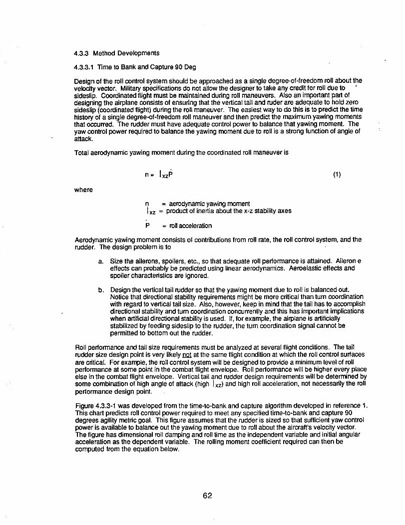
4.3.3 MethodDevelopments
4.3.3.1 "rime to Bank and Capture 90 Deg
Design of the roll control system should be approached as a single degree-of-freedom roll about thevelocity vector. Military specificationsdo not allow the designer to take any credit for rolldue tosideslip. Coordinated flight must be maintained during roll maneuvers. Also an important part ofdesigning the airplane consists of ensuring that the vertical tail and ruder are adequate to hold zerosideslip (coordinated flight) during the roll maneuver. The easiest way to do this is to predict the timehistoryof a single degree-of-freedom rollmaneuver and then predict the maximum yawing momentsthat occurred. The rudder must have adequate control power to balance that yawing moment. Theyaw control power requiredto balance the yawing moment due to roll is a strong function of angle ofattack.
Total aerodynamic yawing moment duringthe coordinated roll maneuver is
n= IxzP (1)
where
n = aerodynamic yawing momentI xz = product of inertia about the x-z stabilityaxes
= rollacceleration
Aerodynamic yawing moment consists of contributionsfrom roll rate, the roll control system, and therudder. The design problem is to
a. Size the ailerons, spoilers,etc., so that adequate roll performance is attained. Aileron eeffects can probably be predicted using linear aerodynamics. Aeroelastic effects andspoiler characteristics are ignored.
b. Design the vertical tail rudder so that the yawing moment due to roll is balanced out.Notice that directional stability requirements might be more critical than turn coordinationwith regard to vertical tail size. Also, however, keep in mind that the tail has to accomplishdirectional stability and turn coordinationconcurrently and this has important implicationswhen artificialdirectional stability is used. If, for example, the airplane is artificiallystabilized by feeding sideslip to the rudder, the turn coordination signal cannot bepermitted to bottom out the rudder.
Roll performance and tail size requirements must be analyzed at several flight conditions. The tailrudder size design point is very likely not at the same flight condition at which the rollcontrol surfacesare critical. For example, the rollcontrol system will be designed to provide a minimum level of rollperformance at some point inthe combat flight envelope. Rollperformance will be higher every placeelse in the combat flight envelope. Vertical tail and rudder design requirements will be determined bysome combination of high angle of attack (high Ixz) and high rollacceleration, not necessarily the rollperformance design point.
Figure 4.3.3-1 was developed from the time-to-bank and capture algorithm developed in reference 1._This chart predicts rollcontrol power required to meet any specified time-to-bank and capture 90degrees agility metric goal. This figure assumes that the rudder is sized so that sufficientyaw controlpower is available to balance out the yawing moment due to roll about the aircraft's velocity vector.The figure has dimensional rolldamping and rolltime as the independent variable and initial angularacceleration as the dependent variable. The rolling moment coefficient required can then becomputed from the equation below.
62
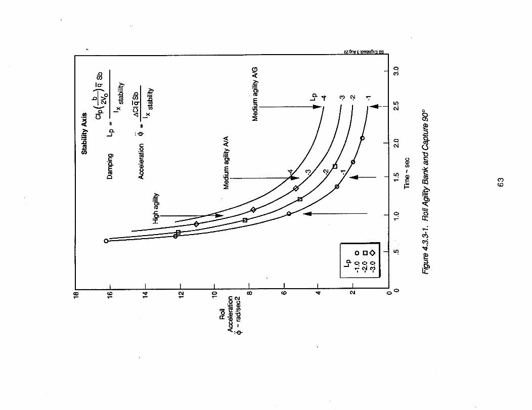
ooI I I I
E
¢'L_I
8_
E
I I I
0
co_o
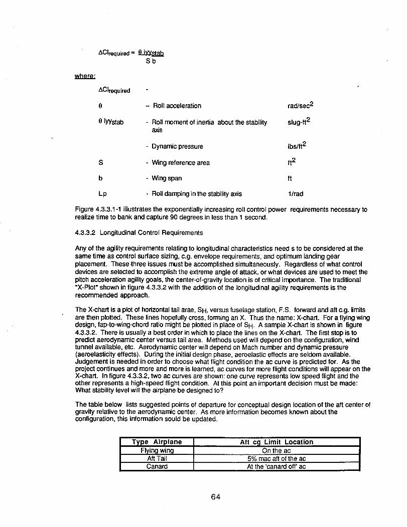
AClrequired=Sb
where.-
ACIrequired
8 - Roll acceleration rad/sec 2
0 lyYstab - Roll moment of inertia about the stability slug-ft2axis
- Dynamic pressure Ibs/ft2
S - Wing reference area ft2
b - Wing span ft
Lp - Roll damping inthe stabilityaxis l/tad
Figure 4.3.3.1-1 illustrates the exponentially increasing roll control power requirements necessary torealize time to bank and capture 90 degrees in less than 1 second.
4.3.3.2 Longitudinal Control Requirements
Any of the agility requirements relating to longitudinalcharacteristics need s to be considered at thesame time as control surface sizing, c.g. envelope requirements, and optimum landing gearplacement. These three issues must be accomplished simultaneously. Regardless of what controldevices are selected to accomplish the extreme angle of attack, or what devices are used to meet thepitch acceleration agility goals, the center-of-gravity location is of critical importance. The traditional"X-Plot" shown in figure 4.3.3.2 with the addition of the longitudinal agility requirements is therecommended approach.
The X-chart is a plot of horizontaltail arae, SH, versus fuselage station, F.S. forward and aft c.g. limitsare then plotted. These lines hopefully cross, forming an X. Thus the name: X-chart. For a flying wingdesign, fap-to-wing-chord ratio might be plotted in place of SH. A sample X-chart is shown in figure4.3.3.2. There is usually a best order in which to place the lines on the X-chart. The first stop is topredict aerodynamic center versus tail area. Methods used will depend on the configuration, windtunnel available, etc. Aerodynamic center will depend on Mach number and dynamic pressure(aeroelasticity effects). During the initial design phase, aeroelastic effects are seldom available.Judgement is needed in order to choose what flight condition the ac curve is predicted for. As theproject continues and more and more is learned, ac curves for more flight conditions will appear on theX-chart. In figure 4.3.3.2, two ac curves are shown: one curve represents low speed flight and theother represents a high-speed flight condition. At this point an important decision must be made:What stability level will the airplane be designed to?
The table below lists suggested points of departure for conceptual design location of the aft center ofgravity relative to the aerodynamic center. As more information becomes known about theconfiguration, this information sould be updated.
Type AirplaneFlying wing
Aft TailCanard
Aft c_l Limit LocationOn the ac
5% mac aft of the acAt the 'canard off' ac
64
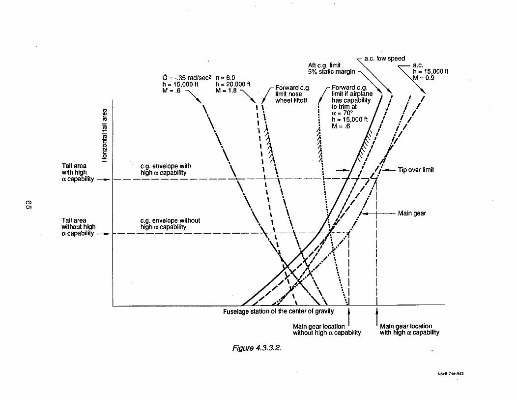
0301
(0
oN
"C0
,1-Taft areawith high(xcapability _
Tail areawithouthigh¢zcapability
(_ = -.35 rad/sec2h = 15,000 ft
M=.6 --_
\$
\$
c.g. envelope withhigh _ capability
n = 6.0h = 20,000 ft
M=1.8 -,_
c.g. envelope withouthighc¢capability
\\\
--IIt
\$
a.c. low speedAft c.g. limit \ _ a.c.
5% static margin -_ "__105._O00ft=./- Forward c.g. /-- Forward c.g. _ _ "%,
/ limit nose / limit if airplane " _, ,p wheel liftoff P has capability i i /
to trim at e I /
_=70o I / /h = 15,000 ft e /
M = .6 ///i -"/
• ------ Tip over limit
• i
/
/=
/
Fuselage station of the center of gravity l
Main gear
Main _lear locationwith htgh ¢xcapability
Figure 4,3.3.2.
spb-8.7-m-Ad3
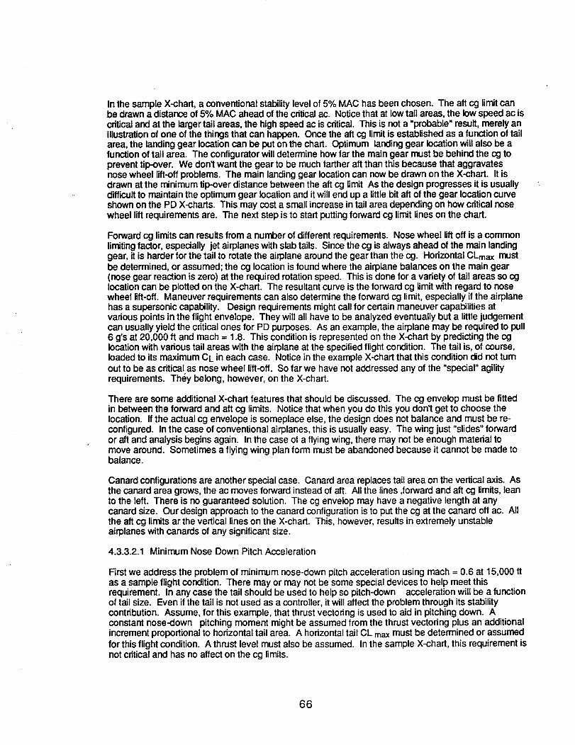
In the sample X-chart, a conventional stability level of 5% MAC has been chosen. The aft cg limit canbe drawn a distance of 5% MAC ahead of the critical ac. Notice that at low tail areas, the low speed ac iscritical and at the larger tail areas, the high speed ac is critical. This is not a "probable" result, merely anillustration of one of the things that can happen. Once the aft cg limit is established as a function of tailarea, the landing gear location can be put on the chart. Optimum landing gear location will also be afunction of tail area. The configurator will determine how far the main gear must be behind the cg toprevent tip-over. We don't want the gear to be much farther aft than this because that aggravatesnose wheel lift-off problems. The main landing gear location can now be drawn on the X-chart. It isdrawn at the minimum tip-over distance between the aft cg limit As the design progresses it is usuallydifficult to maintain the optimum gear location and it will end up a little bit aft of the gear location curveshown on the PD X-charts. This may cost a small increase in tail area depending on how criticalnosewheel lift requirements are. The next step is to start putting forward cg limit lines on the chart.
Forward cg limits can results from a number of different requirements. Nose wheel liftoff is a commonlimitingfactor, especially jet airplanes with slab tails. Sincethe cg is always ahead of the main landinggear, it is harder for the tail to rotate the airplane around the gear than the cg. Horizontal CLmax mustbe determined, or assumed; the cg location is found where the airplane balances on the main gear(nose gear reaction is zero) at the required rotation speed. This is done for a variety of tail areas so cglocation can be plotted on the X-chart. The resultantcurve is the forward cg limitwith regard to nosewheel lift-off. Maneuver requirements can also determine the forward cg limit, especially if the airplanehas a supersonic capability. Design requirements might call for certain maneuver capabilities atvarious points in the flight envelope. They will all have to be analyzed eventually but a littlejudgementcan usuallyyield the criticalones for PD purposes. As an example, the airplane may be required to pull6 g's at 20,000 ft and mach = 1.8. This condition is represented on the X-chart by predicting the cglocation with various tail areas with the airplane at the specified flight condition. The tail is, of course,loadedto its maximum CL in each case. Notice in the example X-chart that this condition did not turnout to be as critical as nose wheel lift-off. So far we have not addressed any of the "special" agilityrequirements. They belong, however, on the X-chart.
There are some additional X-chart features that should be discussed. The cg envelop must be fittedin between the forward and aft cg limits. Notice that when you do this you don1 get to choose thelocation. If the actual cg envelope is someplace else, the design does not balance and must be re-configured. In the case of conventional airplanes, this is usually easy. The wing just "slides" forwardor aft and analysis begins again. In the case of a flying wing, there may not be enough material tomove around. Sometimes a flying wing plan form must be abandoned because it cannot be made tobalance.
Canard configurations are another special case. Canard area replaces tail area on the vertical axis. Asthe canard area grows,the ac moves forward instead of aft. All the lines ,forward and aft cg limits, leanto the left. There is no guaranteed solution. The cg envelop may have a negative length at anycanard size. Our design approach to the canard configurationis to put the cg at the canard off ac. Allthe aft cg limitsar the vertical lines on the X-chart. This, however, results in extremely unstableairplanes with canards of any significantsize.
4.3.3.2.1 Minimum Nose Down Pitch Acceleration
Firstwe address the problem of minimum nose-down pitch acceleration using mach = 0.6 at 15,000 ftas a sample flight condition. There may or may not be some special devices to help meet thisrequirement. In any case the tail should be used to help so pitch-down acceleration will be a functionof tail size. Even if the tail is not used as a controller, it will affect the problem through its stabilitycontribution. Assume, for this example, that thrust vectoring is used to aid in pitching down. Aconstant nose-down pitching moment might be assumed from the thrust vectoring plus an additionalincrement proportionalto horizontal tail area. A horizontal tail CL max must be determined or assumedfor this flight condition. A thrust level must also be assumed. In the sample X-chart, this requirement isnot criticaland has no affect on the cg limits.
66
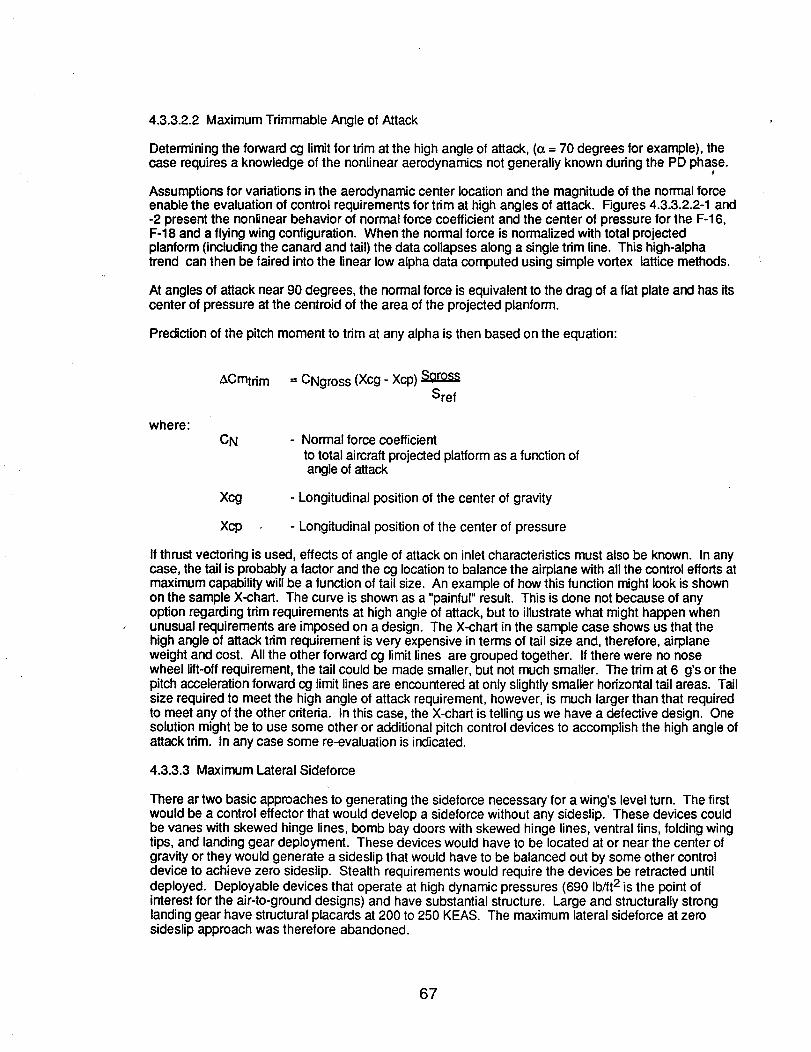
4.3.3.2.2 Maximum Trimmable Angle of Attack
Determining the forward cg limit for trim at the highangle of attack, ((_= 70 degrees for example), the
case requires a knowledge of the nonlinear aerodynamics not generally known during the PD phase.
Assumptions for variations in the aerodynamic center location and the magnitude of the normal forceenable the evaluation of control requirements for trim at high angles of attack. Figures 4.3.3.2.2-1 and-2 present the nonlinear behavior of normal force coefficient and the center of pressure for the F-16,F-18 and a flying wing configuration. When the normal torce is normalized with total projectedplanform (includingthe canard and tail) the data collapses along a singletrim line. This high-alphatrend can then be faired into the linear low alpha data computed using simple vortex lattice methods.
At angles of attack near 90 degrees, the normal force is equivalent to the drag of a flat plate and has itscenter of pressure at the centroid of the area of the projected planform.
Predictionof the pitch moment to trim at any alpha is then based on the equation:
ACmtdm = CNgross (Xcg : Xcp)Sref
where:CN - Normal force coefficient
to total aircraft projected platformas a function ofangle of attack
Xcg - Longitudinal position of the center of gravity
Xcp - Longitudinal position of the center of pressure
If thrust vectoring is used, effects of angle of attack on inlet characteristics must also be known. In anycase, the tail is probably a factor and the cg location to balance the airplane with all the control efforts atmaximum capability will be a function of tail size. An example of how this function might look is shownon the sample X-chart. The curve is shown as a "painful" result. This is done not because of anyoption regarding trim requirements at high angle of attack, but to illustrate what might happen whenunusual requirements are imposed on a design. The X-chart in the sample case shows us that thehigh angle of attack trim requirement is very expensive in terms of tail size and, therefore, airplaneweight and cost. All the other forward cg limit lines are grouped together. If there were no nosewheel lift-off requirement, the tail could be made smaller, but not much smaller. The trim at 6 g's or thepitch acceleration forward cg limit lines are encountered at only slightly smaller horizontal tail areas. Tailsize required to meet the high angle of attack requirement, however, is much larger than that requiredto meet any of the other criteria. In this case, the X-chart is telling us we have a detective design. Onesolution might be to use some other or additional pitch control devices to accomplish the high angle ofattack trim. In any case some re-evaluation is indicated.
4.3.3.3 Maximum Lateral Sideforce
There ar two basic approaches to generating the sideforce necessary for a wing's level turn. The firstwould be a control effector that would develop a sideforce without any sideslip. These devices couldbe vanes with skewed hinge lines, bomb bay doors with skewed hinge lines, ventral fins, folding wingtips, and landing gear deployment. These devices would have to be located at or near the center ofgravity or they would generate a sideslip that would have to be balanced out by some other controldevice to achieve zero sideslip. Stealth requirements would require the devices be retracted untildeployed. Deployable devices that operate at high dynamic pressures (690 Ib/ft2 is the point ofinterest for the air-to-ground designs) and have substantial structure. Large and structurally stronglanding gear have structural placards at 200 to 250 KEAS. The maximum lateral sideforce at zerosideslip approach was therefore abandoned.
67
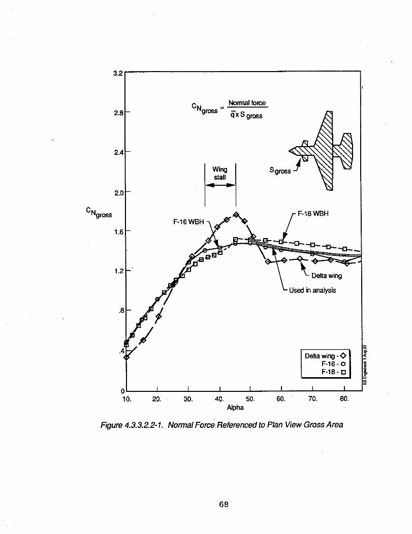
3.2!
2.8
2.4
2.0
CNgross
1.6
Normal force
CNgr°ss = q'x S gross
Wingstall
F-16 WBH
Sgros s_<
F-18 WBH
Delta wing
Used in analysis
Delta wing - <>F-16- 0F-18 - El
I I
10. 20. 30. 40. 50. 60. 70. 80.
Alpha
Figure 4.3.3.2.2-1. Normal Force Referenced to Plan View Gross Area
68
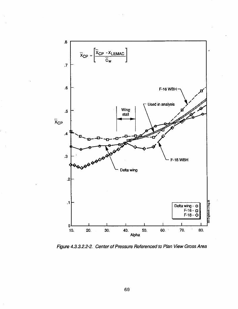
XCp
.8
.7
XCp = [Xcp "XLEMAC t
Wingstall
F-16 WBH
Used in analysis
F-18 WBH
Delta wing
.1-
Deka wingF.18F.16"_ I
I I0 I I I I I10. 20. 30. 40. 50. 60. 70. 80.
Alpha
Figure 4.3,3.2.2-2. Center of Pressure Referenced to Plan View Gross Area
69
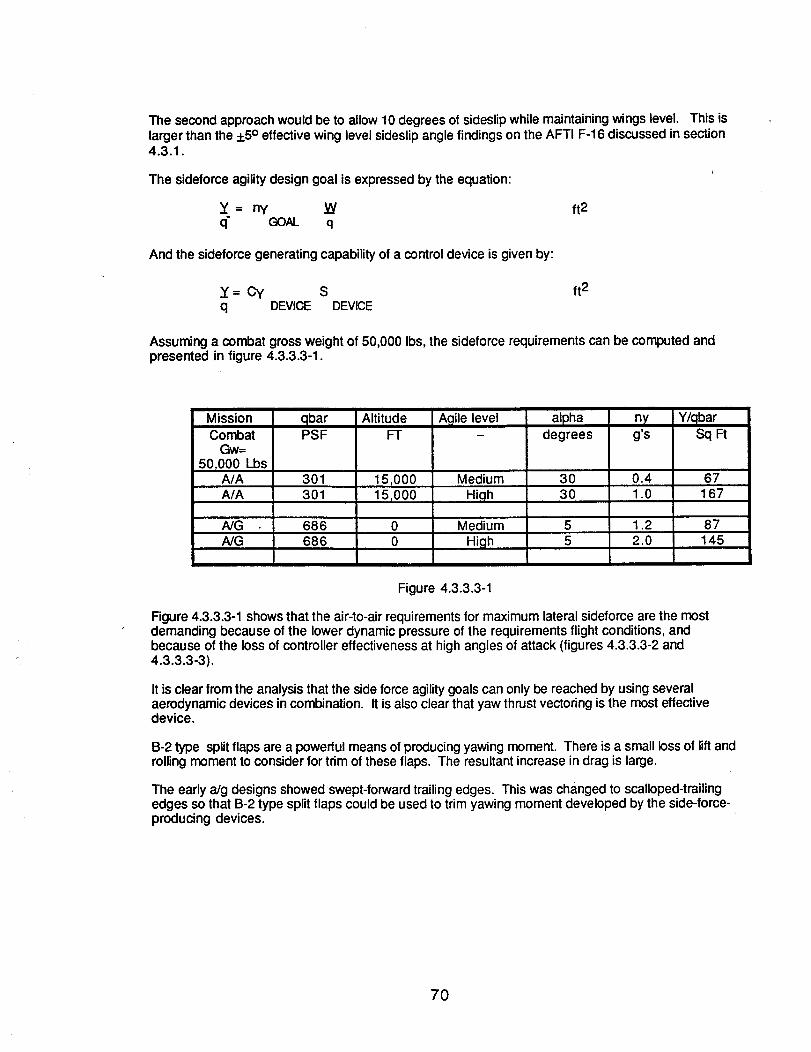
The second approach would be to allow 10 degrees of sideslip while maintaining wings level. This islarger than the +5° effective wing level sideslip angle findings on the AFTI F-16 discussed in section4.3.1.
The sideforce agility design goal is expressed by the equation:
_' = ny _/ ft2q" GOAL q
And the sideforce generating capability of a control device is given by:
= Cy S ft2q DEVICE DEVICE
Assuming a combat gross weight of 50,000 Ibs, the sideforce requirements can be computed andpresented in figure 4.3.3.3-1.
MissionCombat
Gw=50T000 Lbs
A/A
qbarPSF
301A/A 301
NGNG
686686
AltitudeFT
15,000151000
Agile level
MediumHigh
MediumHigh
alphadegrees
3030
nyg's
0.41.0
1.22.0
Y/qbarSq Ft
67167
87145
Figure 4.3.3.3-1
Figure 4.3.3.3-1 shows that the air-to-air requirements for maximum lateral sideforce are the mostdemanding because of the lower dynamic pressure of the requirements flight conditions, andbecause of the loss of controller effectiveness at high angles of attack (figures 4.3.3.3-2 and4.3.3.3-3).
It is clear from the analysis that the side force agility goals can only be reached by using severalaerodynamic devices in combination. It is also clear that yaw thrust vectoring is the most effectivedevice.
B-2 type splitflaps are a powerful means of producing yawing moment. There is a small loss of lift androlling moment to consider for trim of these flaps. The resultant increase in drag is large.
The early aJg designs showed swept-forward trailing edges. This was changed to scalloped-trailingedges so that B-2 type split flaps could be used to trim yawing moment developed by the side-force-producing devices.
7O
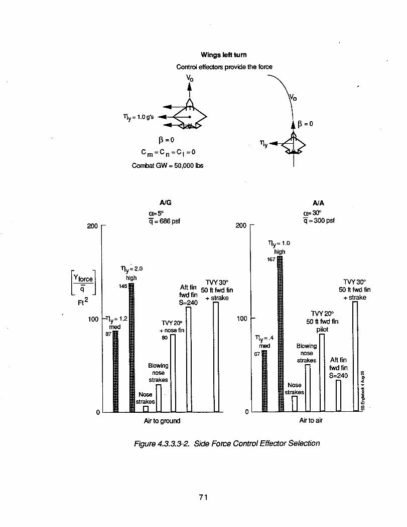
Wings left turn
Control eflectors provide the force
Vo
13=0
Cm=Cn=CI=0
Combat GW = 50,000 Ibs
200
Ft2
I00
A/G
o_.5o- =686psf
11y"-2.0high
145 Aft finfwd finS=240
TVY20o.2 + nosefin
"NBlowing
nose Jl
strakesJJNose _. II
str_es U U
TVY 30°50 ftfwd fin
+ strake
20O
I lly = 1.0high
100
I
67
0
A/A
(z=30°_= 300 psf
TVY 20°50 ft fwd fin
pibt
Blowingnose
strakes Aft finfwd finS=240
Airto ground Airto air
TVY 30°50 tt fwd fin
+ strake
Figure 4.3.3.3-2. Side Force Control Effector Selection
71
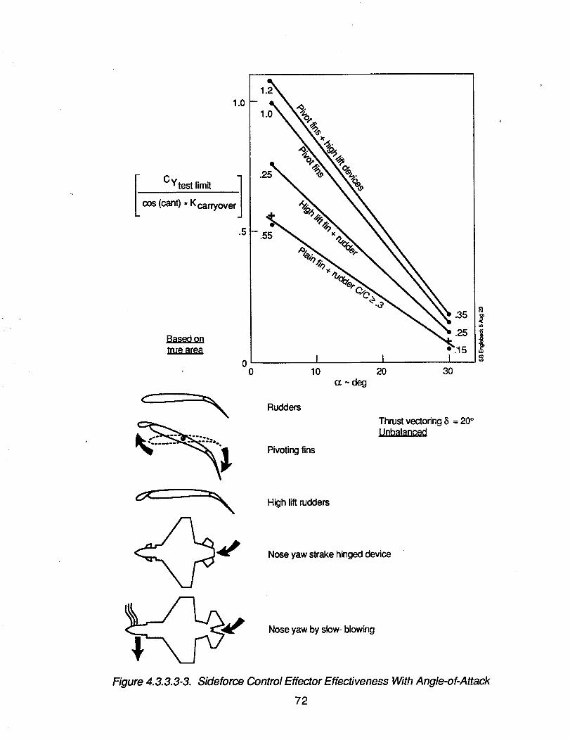
1.0
I CYtest limitcos (cant). K carryover
.5
Basedontrue area
1
1
0 I I I0 10 20 30
o_~ deg
Rudders
Pivoting fins
High lift mddem
Nose yaw strake hinged device
Nose yaw by slow-blowing
Thrust vectoring5 = 20°Unbalanced
Figure 4.3.3.3-3. Sideforce Control Effector Effectiveness With Angle-of-Attack
72
4.3.4 Configuration Evaluation
4.3.4.1 Agility Impact on Low Observable Configurations
A vortex lattice model of the air-to-ground flying wing concept is shown in figure 4.3.4.1-1. Theaerodynamic characteristics shown in figure 4.3.4.1-2 are the results from the vortex lattice method. Tl_eflight condition shown is a combat gross weight of 58,270 Ib and an airspeed of 450 KEAS.
Both the high agilityand low agilityversions of this aircraft have the control power necessary to trim at the9g limit load factor. This limitload occurs at an angle-of-attack of 10 degrees because of the lowwingloading of the flying wing concept. The trim at this 9g condition requires less than a 10-degree trailingedge up deflection from the inboard flaps. An alpha limiterwill be required to prevent inadvertentexcursions outside the aircraft structural envelope. Limited pitch thrust vectoring in combination withtrailing edge flaps yield a responsive capability in load factor while retaining powerful control power foralpha limiting.
The time to bank and capture 90 degrees was accomplished using the method outlined in section4.3.3.1. The results are summarized in figure 4.3.4.1-3.
The time to bank and capture 90-degree agilityrequirements are well within this configurations ability toachieve. The yaw control pwoer to balance the rolluses only 10% of the total available yaw control power.
A combination of four control effectors were used to meet the maximum lateral side force agilityrequirements. The control effectors and their contributionto the lateral side force are shown in figure4.3.4.1-2.
The engine thrust is the dominate control effector, contributing 57% of the control power for the medium-agilityaircraft and 77% of the control power for the high-agilityaircraft. The aircraft T/W requiredto meetthe high-agility level is 1.6, well outside what could be reasonably expected to be available on a fighter.
A smart digital flight-control system is required for the effective integration of the control effectors shownin figure 4.3.4.1-4. The rollcoupling from the B-2 type splitflaps were found to be small. Yaw controlduringthe side force maneuver can be achieved by differentiallyvarying split flap deflections or yaw thrustvectoring.
Xaw thrust vectoring is the most effective side force producingcontrol effector. Oversizing the enginewould translate into gains into maneuver performance at the expense of aircraft weight and range.Aerodynamic control effectors to achieve the side force requirements would increase the weight of theaircraft without any additional synergistic improvements anywhere except for the maximum lateral sideforce.
4.3.4.2 Observables Impact of High Agility Designs
The vortex lattice model presented in figure 4.3.4.2-1 is a high agility moderate observable air-to-air fighterconcept. The aerodynamics resulting from the vortex lattice analysis is presented in figure 4.3.4.2-2.Figure 4.3.4.2-3 presents the agility levels achieved by the concept aircraft broken down by controleffector.
The pitch control power to trim the aircraft at high angles of attack is much greater than that required tomeet the nose down pitch acceleration agilityrequirements. Pitchthrust vectoring is again the mosteffective control effector. The ability to trim the aircraft at 70 degrees angle-of-attack will require thecombined use of pitch vectoring and over-rotating the horizontal tail.
73
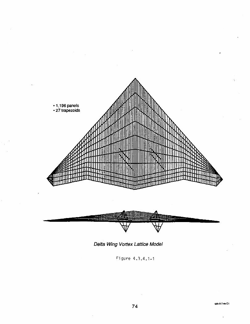
• 1,196 panels• 27 trapezoids
Delta Wing Vortex Lattice Mode/
Figure 4.3.4.1-I
74 sl_8-7-m-C1
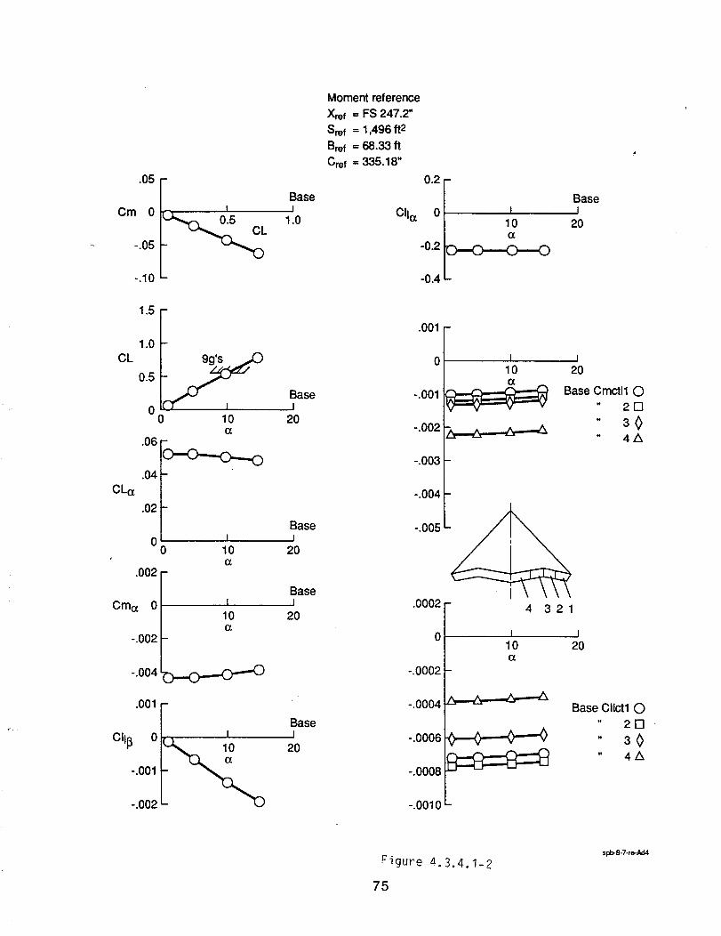
.05
Cm 0
-.05
-.10
BaseI
1.0
Moment reference
Xref = FS 247.2"Sref = 1,496 ft 2
Bref = 68.33 ft
Ore f = 335.18"
CIl¢z
0.2
0
-0.2
-0.4
10
BaseI
2O
CL
CL(z
I IE
.06 _
.04
.02
I00 10
G.002
Cm(z 0
-.002
-.004
.001
10(z
.o.--o---o
-.002
I
Basei
20
BaseI
2O
BaseI
20
BaseI
2O
.001
0
-.001
-.002
-.003
-.004
-.005
.0002
0
-.0002
-.0004
-.0006
-.0008
-.0010
I I101
20
Base Cmctll 0" 2D
" 30" 4ZX
4 321
I I10 20(z
Base CIIctl 0" 2D
- 3<>_ " 4A
Figure m.3.4.1-2
75
spb-8-7-re-Ad4
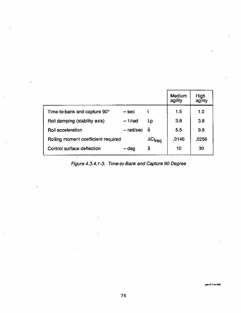
Time-to-bank and capture 90 °
Roll damping (stability axis)
Roll acceleration
Rolling moment coefficient required
Control surface deflection
- sec t
- 1/rad Lp
- rad/sec
ACIreq
- deg
Mediumagility
1.5
3.8
5.5
.0146
10
Highagility
1.0
3.8
9.8
.0256
30
Figure 4.3.4.1-3. Time-to-Bank and Capture 90 Degree
spb-8-7-re-Ad9
76
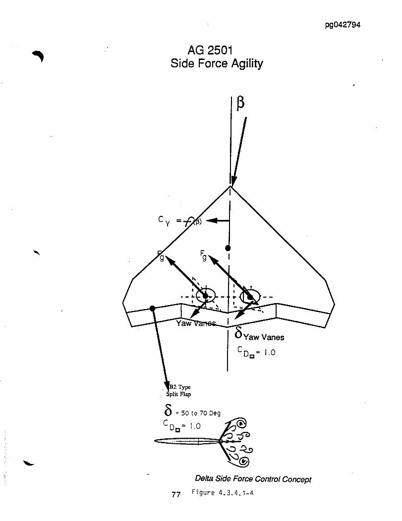
pg042794
AG 2501Side Force Agility
Vanes
CD= = l.O
Flap
(_ =50to70Deg
C D= = 1.0 _'_
Delta Side Force Control Concept
77 Figure 4.3.4.1-z_
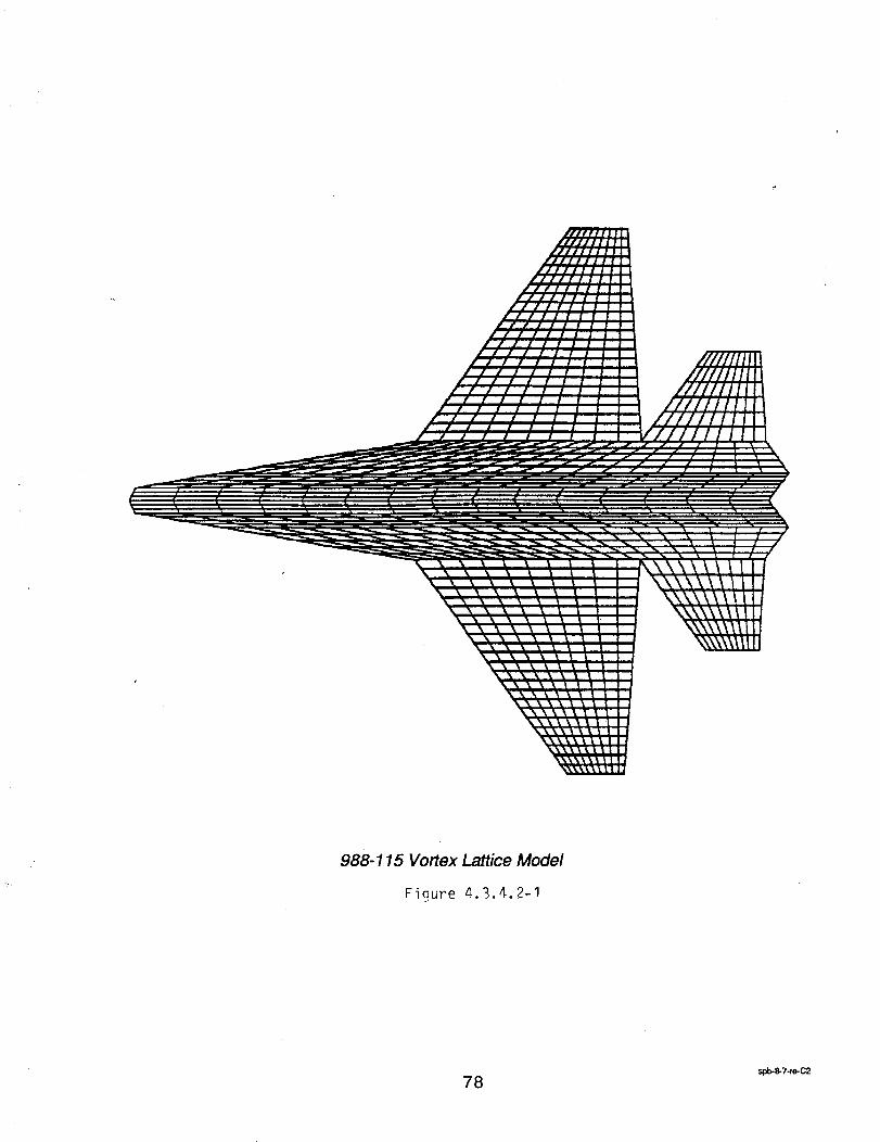
988-115 Vortex Lattice Model
Figure 4.3.4.2-I
spb-8-7-te-C2
78
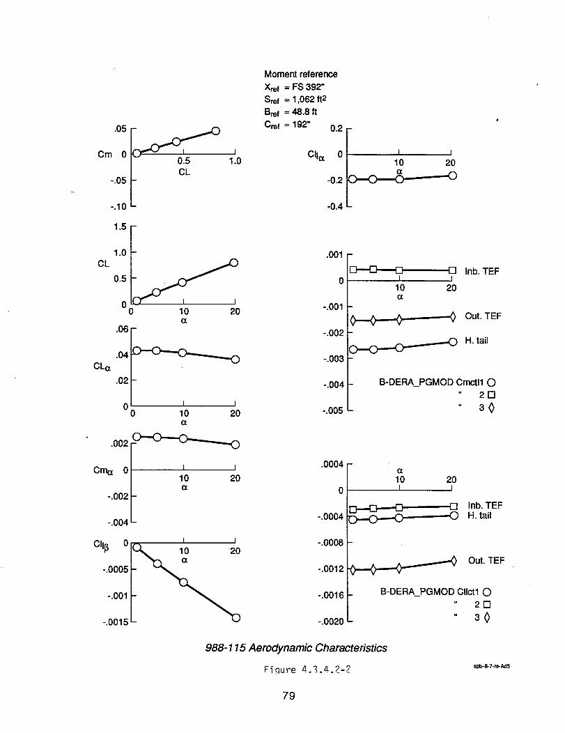
.05
Cm 0
-.05
-.10
1.5
0.5 1.0CL
Moment reference
Xref = FS 392"Sref -- 1,062 ft2
Bref = 48.8 ft
Cre! = 192" 0.2
CIIcc 0
-0.2
-0.4
I I
10 20
-0
CL1.0 --
0.5
0O- 10 20
(z.06 -
CL(z
.04
.02
0
.002
-<i)
I I0 10 20
Cma 0
-.002
-.004
I I10 20o[
Clll3 o
-.0005
-.001
-.0015
I I
.001
0
-.001
-.002
-.003
-.004
-.005
.0004
0
-.0004
-.0008
-.0012
-.0016
-.0020
I10(z
o.-.o---o-
[] Inb. TEFI
20
-J_ Out. TEF
--fO H. tail
B-DERA_PGMOD Cmctll C)" 21-1
" 30
(z10 20I I
,,I-I Inb. TEF0 H. tail
__.(_.,.,=_.,,.,,.._ Out. TEF
B-DERA_PGMOD CIIctl O" 2D
" 30
988-115 Aerodynamic Characteristics
Figure 4.3.4.2-2 spb-8-7-re-Ad5
79
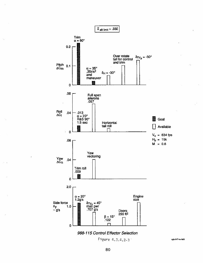
0.2
Trim(x= 60°
aft limit = .33C I
PitchACm
0.1
0
.08
Roll .04ACI
(7.=35 °
.35r/s2andmaneuver
Full spanailerons.057
m
-- .013o¢= 20 °R&S 90°1.5 sec
|.08 --
Over rotatetail for controland trim
17
_H = -30° II
II
_51_V_p = -30°
Horizontaltail roll
r7
Yaw .04ACn
0
Trim roll.009
|
Yawvectoring
m
I
2.0
o
Side force
ny, 1.0~gs
0
OTVy = 45 °
max pwr.707 g's
= 15°.122
[-1
Enginesize
Doors _-I
290 ft 2
M988-115 Control Effector Selection
Figure 4.3.,_. 2-3
B Goal
D Available
Vo = 634 fps
Hp = 15kM = 0.6
sl:_.8-7-re-Ad8
80
Roll control power is sufficientto meet the time-to-bank and capture 90 degrees agility requirement.Sufficient yaw control power is available to balance the yawing moment generated by the rollabout thevelocity vector.
Side force is dependent on yaw thrust vectoring as were the low observable designs presented in the ,previous section.
One of the key design traits of low observable designs is the emphasis on keeping the number of controlsurfaces down to a minimum. The most obvious impact is the lack of control surfaces available to addressany handling quality or agility requirement. Side sector signature is completely counter to the availability ofefficient lateral control devices to meet the maximum lateral side force agility requirements. Any significant
_"side sector signature requirement drives the aircraft to a highly coupled V-tail configuration and eventuallyto eliminating the tails altogether. Analysis has shown that yaw thrust vectoring is the most effectivecontrol effector in achieving the maximum la_teralside force agility requirements.
The signature impact on longitudinal agility requirements are not as extreme as that of the lateral-directional agility just discussed. This observation is primarily due to the horizontal orientation of the mosteffective pitch control effectors is favorable to signature requirements. Even with the availability ofnumerous options for pitch control effectors, pitch thrust vectoring is the most effective control effector.
Time to bank and capture 90 degrees does not seem to be affected by the signature issue. This isbecause the most effective roll control devices have the favorable horizontal orientation and wing aileronsseem to have the control power necessary to meet the agility requirements
81
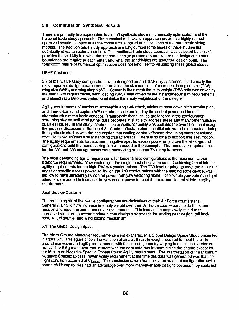
5.0 Conflauratlon Synthesis Results
There are primarily two approaches to aircraft synthesis studies, numerically optimization and thetraitionai trade study approach. The numerical optimization approach provides a highly refinedoptimized solution subject to all the constraints supplied and limitationsof the parametric sizingmodels. The tradition trade study approach is a long cumbersome series of trade studies thateventually reveal an optimal solution. The traditional trade study approach was selected because itprovides the visibility into what the important design parameters are, where the design constraintboundaries are relative to each other, and what the sensitivities are about the design point. The"blackbox" nature of numerical optimization does not lend itself to visualizing these global issues.
USAFCustomer
Six of the twelve study configurations were designed for an USAF only customer. Traditionally themost important design parameters determining the size and cost of a concept is engine size (T/W),wing size (W/S), and wing shape (AR). Generally the aircraft thrust-to-weight (T/W) ratio was driven bythe maneuver requirements, wing loading (W/S) was driven by the instantaneous turn requirements,and aspect ratio (AR) was varied to minimize the empty weight/cost of the designs.
Agility requirements of maximum achievable angle-of-attack, minimum nose down pitch acceleration,and time-to-bank and capture 90° are primarily determined by the control power and inertialcharacteristics of the basic concept. Traditionally these issues are ignored in the configurationscreening stages untilwind tunnel data becomes available to address these and many other handlingqualities issues. In this study, control effector sizing for agilitywas built into the overall concept usingthe process discussed in Section 4.3. Control effector volume coefficients were held constant duringthe synthesis studies with the assumption that scaling control effectors size using constant volumecoefficients wouldyield similar handling characteristics. There is no data to support this assumption.The agility requirements for maximum negative specific excess power only drove the air-to-groundconfigurations until the maneuvering flap was added to the concepts. The maneuver requirementsfor the A/A and A/G configurations were demanding on aircraft T/W requirements.
The most demanding agilityrequirements for these tailless configurations is the maximum lateralsideforce requirements. Yaw vectoring is the single most effective means of achieving the sideforceagility requirements for the high T/W A/A configurations. The T/W level required to meet the maximumnegative specific excess power agility, on the A/G configurations with the leading edge device, wastoo low to have sufficientyaw control power from yaw vectoring alone. Deployable yaw vanes and splitailerons were added to increase the yaw control power to meet the maximum lateral sidefore agilityrequirement.
Joint Service Customer
The remaining six of the twelve configurations are derivatives of their Air Force counterparts.Generally, a 15 to 17% increase in empty weight over their Air Force counterparts to do the samemission and meet the same maneuver requirements. This increase in empty weight is due toincreased structure to accommodate higher design sink speeds for landing gear design, tail hook,nose wheel shuttle, and wing folding mechanism.
5.1 The Global Design Space
The Air-to-Ground Maneuver requirements were examined in a Global Design Space Study presentedin figure 5.1. This figure shows the variation of aircraft thrust-to-weight required to meet the air-to-ground maneuver and agility requirements with the aircraft geometry varying in a historically relevanttrend. The 6.5g maneuver requirement was the dominate requirement sizing the engine except forthe Maximum Negative Specific Excess Power Agility requirement. The interpretation of the MaximumNegative Specific Excess Power Agility requirement at the time this data was generated was that theflight condition occurred at CLmax. The conclusion drawn from this chart was that configuration swithpoor high lift capabilities had an advantage over more maneuver able designs because they could not
82
reachthesamehighliftconditions.ThereforetheMaximumNegativeSpecificExcessPowerAgilityrequirementwasmodifiedtooccurataconstant load factor to negate influence of obtainable CLmax.
Similar historically relevant trend data were used to examine the global design space of the air-to-airmaneuver requirements. The results presented in figure 5.2 show that the medium agility level ofMaximum Negative Specific Excess Power requirement does not drive the size of the enginerequired. The high agility levels match the maneuver requirements. Concern about the transonic,acceleration requirements are only relevant at the low wing loading, high aspect ratio portions of thedesign space. Expected aircraft thrust-to-weight ratios in configuration sizing trade will be from 1.1to 1.3.
83
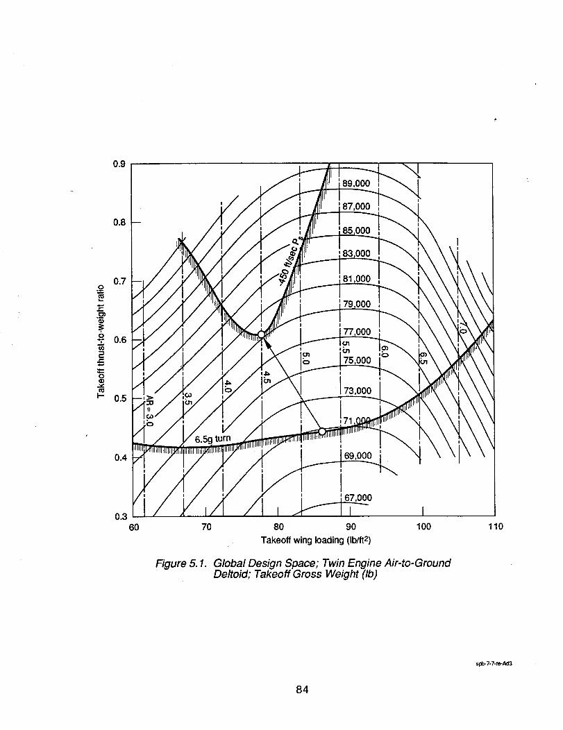
.o_
¢.-
¢=
0
2
0
I--
0.9
0.8
0.7
0.6
0.5
0.4
0.360
89,000
87,000
000
I
i73,000
0
6.sg
Figure 5.1.
70
!
69,000
000
80 90
Takeoff wing loading (Ib/ft2)
100
Global Design Space; Twin Engine Air-to-GroundDeltoid; Takeoff Gross Weight (Ib)
110
spb-7-7-re-Ad3
84
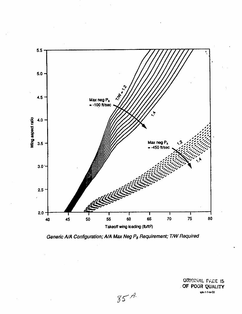
Max neg P== -100 ft/seo
Max neg P= ,_.q,= 450 ft/sec
i I I I
40 45 50 55 60 65 70 75
Takeoff wing loading (Ib/It 2)
Generic AJA Configuration; A/A Max Neg Ps Requirement; T/W Required
80
OR,G,,_,_ F;:.CE IS
OF POOR "QUALITY
_:=-7.7-r_

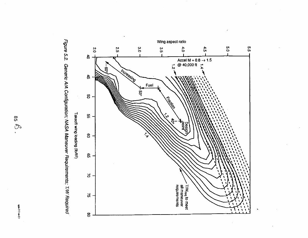
GOO"1
I
=o
GObI
O
Wing aspect ratio
•_ .1=.b LnI I
Accel M = 0.8 -_ 1.5@ 40,000 It ..-=
Fuel
bI
I
I
I
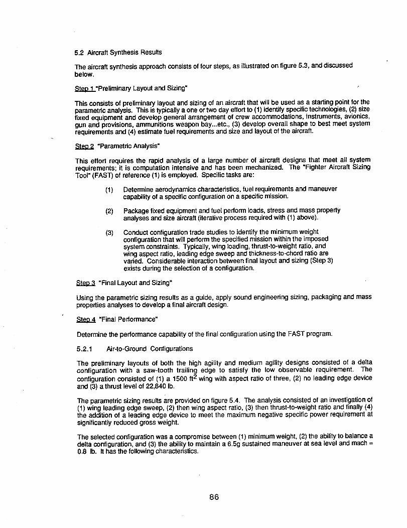
5.2 Aircraft Synthesis Results
The aircraft synthesis approach consists of four steps, as illustratedon figure 5.3, and discussedbelow.
=_p,,12..l_"PreliminaryLayout and Sizing"
This consists of preliminary layout and sizing of an aircraft that will be used as a starting point for theparametric analysis. This is typically a one ortwo day effort to (1) identify specifictechnologies, (2) sizefixed equipment and develop general arrangement of crew accommodations, instruments, avionics,gun and provisions, ammunitions weapon bay...etc., (3) develop overall shape to best meet systemrequirements and (4) estimate fuel requirements and size and layout of the aircraft.
"Parametric Analysis"
This effort requires the rapid analysis of a large number of aircraft designs that meet all systemrequirements; it is computation intensive and has been mechanized. The "Fighter Aircraft SizingTool" (FAST) of reference (1) is employed. Specific tasks are:
(i) Determine aerodynamics characteristics, fuel requirements and maneuvercapability of a specific configuration on a specific mission.
(2) Package fixed equipment and fuel perform loads, stress and mass propertyanalyses and size aircraft (iterative process required with (1) above).
(3) Conduct configuration trade studies to identify the minimum weightconfiguration that will perform the specified missionwithin the imposedsystem constraints. Typically, wing loading, thrust-to-weight ratio, andwing aspect ratio, leading edge sweep and thickness-to-chord ratio arevaried. Considerable interaction between final layout and sizing (Step 3)ex}sts during the selection of a configuration.
"Final Layout and Sizing"
Using the parametric sizing results as a guide, apply sound engineering sizing, packaging and massproperties analyses to develop a final aircraft design.
"Final Performance"
Determine the performance capability of the final configuration using the FAST program.
5.2.1 Air-to-Ground Configurations
The preliminary layouts of both the high agility and medium agility designs consisted of a deltaconfiguration with a saw-tooth trailing edge to satisfy the low observable requirement. Theconfiguration consisted of (1) a 1500 ft2 wing with aspect ratio of three, (2) no leading edge deviceand (3) a thrust level of 22,840 lb.
The parametric sizing results are provided on figure 5.4. The analysis consisted of an investigation of(1) wing leading edge sweep, (2) then wing aspect ratio, (3) then thrust-to-weight ratio and finally (4)the addition of a leading edge device to meet the maximum negative specific power requirement atsignificantly reduced gross weight.
The selected configuration was a compromise between (1) minimum weight, (2) the ability to balance adelta configuration, and (3) the ability to maintain a 6.5g sustained maneuver at sea level and mach =0.8 lb. It has the following characteristics.
86
Technology
Step I
l re" ina requirements layout andsB.=ng
Step 2
Parametric sizing
Identify minimumweightconfigurationthat meetsall system requirements
Fighter Aircraft SizingTool (FAST)
Step 3
Finallayout ands_.mg
Step 4
_..I Finalperformance
Figure 5.3. Aircraft Synthesis Approach
spb-5/94-re-Ad2
87

A
Q¢:>v
._m
(/}¢/)
2C9
88
86
84,<
,_ Max neg Ps=
// .... _-s95
_; S = 1,500 ft 2• AR -- 3.0• No LED• T = 22,840 Ib
EVA I I I40 45 50
Wing leading edge sweep (deg)
55
A
.o00o
¢,.-._m
¢/}
2(.9
85
84-
-700
_Max neg Ps =
- "__._-550• S = 1,500 ft2• ALE = 52.5 deg• No LED• T = 22,840 Ib
I I I3.0 3.5 4.0
Wing aspect ratio
4.5
+300 I I I I I
+200
+100
v
oY_ 0
X
-100
-500
• S = 1,462 it 2• AR = 3.5• ALE = 48.75 deg
High. agilityrequ,rement
80,000 Ib
Thrust-to-weight ratio0.5 0.6 0.7
85,0001b
I I I= 75,000 Ib
Selected configurationLeading edge deviceMinimum T/W • GW = 73,820 Ibto maintain • Max neg Ps = -58 90,000 Ib6.5 g'ssustainedload factor 85,000 Ib
GW = 80,000 Ib
90,000 Ib
I I I I I I I
I
100,000 Ib
95,0001b
Figure 5.4. Air-to-Ground Configuration Sizing Charts
spb-5/94-re-Ad 1
88
• Wing area = 1462 ft2• Aspect ratio = 3.5• Wing leading sweep = 48.75 degs• Thrust-to-weight ratio 0.336• Gross weight = 73,820 Ib
The same configuration was selected for both the high agility and medium agility design because itrepresents the minimum weight design. As shown on figure 5-4, it is possible to satisfy the 450 fpsmaximum negative specific power requirement of the medium agilitydesign, but the weight is greater.
The important design parameters are tabulated in the order of significance in table 5.5. The leadingedge device provides a significantweight reduction due to its aerodynamic effect, as shown on figure5.7. It provides a significant improvement in left coefficient at low angles of attack and a slightlyimproved maximum liff-to-dragratio.
The design sensitivities about the design point are provided on table 5.6. Another interestingsensitivity, although it is not about the design point, is provided on figure 5.8. Presently, therequirement is to calculate the maximum negative specific power at the point in the mission where60% of the fuel remains on board. If this requirement were changed to 50% fuel remaining on board,the aircraft gross weight could be reduced 6,700 Ibs.
5.2.2 Air-to-Air Configurations
High Aailitv
The a variation of aircraft gorss weight with the significant design parameters and design constraintboundaries is illustrated on the configuration sizing chart on figure 5.9. The chart was constructe(;Iwith a thrust-to-weight ratio of 1.125 which allows a small design space betweenthe sustained loadconstraint of 4.4 g's (H = 20,000 It at M = 0.6) and the specific power constraint of 550 fps (M = 30,000ft at M = 0.9). The other twenty-four constraints are all satisfied. Note that the minimum weight designoccurs at an aspect ratio of approximately 5.5. It is anticipated that this design would be subject to asevere weight penalty due to flutter. Without a detailed analysis, we have selected a design with alower aspect ratio to avoid flutter. The selected configuration lies on the sustained load designconstraint at an aspect ratio of 3.75. It has a gross weight of 59,835 lb. Other characteristics aretabulated on figure 5.9.
Medium Agility
The variation of aircraft gross weight with the significant design parameters and design constraintboundaries is illustrated on the configuration sizing chart on figure 5.10. The chart was constructedwith a thrust-to-weight ratio of 1.13 which allows a small design space between the instantaneous loadconstraint of 9 g's (M = 30,000 It at M = 0.9) and the specific power constraint of 550 fps (H = 30,000 ftat M = 0.9). Again, the minimum weight configuration occurs at a higher aspect ratio, but aconfigurationwith an aspect ratio of 4.0 was selected to avoid flutter.
5.2.3 Multi-Role Configurations
Hiah Aailitv
The variation of aircraft gross weight with the significant design parameters and design constraintboundaries is illustrated on the configuration sizing chart on figure 5.11. The chart was constructedwith a thrust-=to-weight ratio of 1.1 which allows a small design space between the sustained loadconstraint of 4.4 g's (H = 20,000 ft at M = 0.6) and the specific power constraint of 550 fps (H = 30,000ft at M = 0.9). The other twenty-four constraints are all satisfied. Although a slight weight saving isindicated at higher aspect ratios, a configuration with aspect ratio of 4.38 and wing loading of 67.5 psfwas selected to avoid flutter.
89
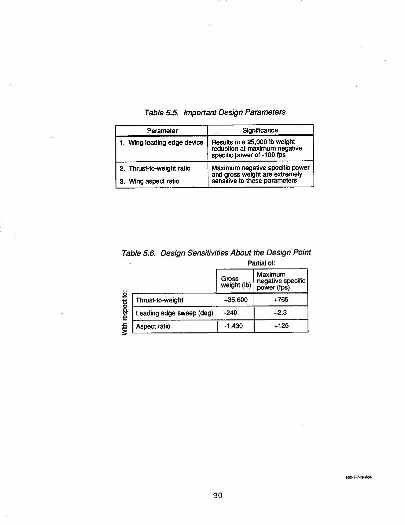
Table 5.5. Important Design Parameters
Parameter
1. Wing leading edge device
2. Thrust-to-weight ratio
3. Wing aspect ratio
Significance
Results in a 25,000 Ib weightreductionat maximum negativespecific power of -100 fps
Maximum negative specific powerand 9ross weight are extremelysensitive to these parameters
Table 5.6.
Q)r_
r'-
Design Sensitivities About the Design Point
Partial of:
Gross
weight (Ib)
Maximumnegative specificpower (fps)
Thrust-to-weight +35,600 +765
Leading edge sweep (deg) -240 +2.3
Aspect ratio -1,430 +125
spb-7-7-re-Ad4
9O
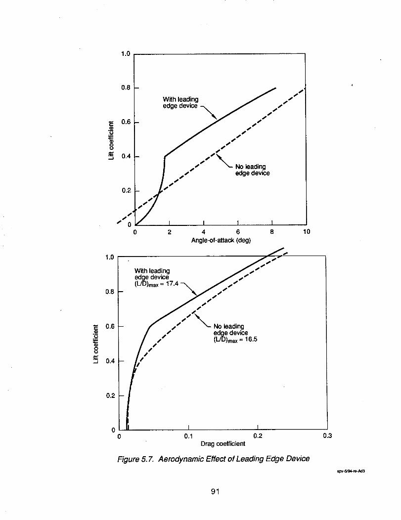
._o:I=(l)
8.m.-J
._o
8
,.J
1.0
0.8
0.2
0
With leading / ss SS
edge device -._ / sSSs S
SSSS S
/ "(s SSSSS No leading
I s S" edge device
ISS S
I I I I2 4 6 8
Angle-of-attack (deg)
10
With leadingedge device(L/D)max= 17.4
No leadingedge device(L/D)max= 16.5
I I0 0.1 0.2 0.3
Drag coefficient
Figure 5. 7. Aerodynamic Effect of Leading Edge Device
spv.SF34.re-Ad3
91
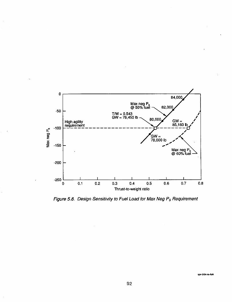
=£
C
X¢;
0 8,,oo0//Max neg Ps
@ 50% fuel _82,000#/J" 4
T/W = 0.543 _/" #GW = 78,450 Ib -_ 80.000,._ ,-,,,, /
¢u,uuuj GW = ,/
/ 78,000 Ib_,s"
Max neg Ps_@ 60% fuel
-50
-100
-150
-200
High agilityrequirement
-250 I I I I I I I0 0.1 0.2 0.3 0.4 0.5 0.6 0.7 0.8
Thrust-to-weight ratio
Figure 5.8. Design Sensitivity to Fuel Load for Max Neg Ps Requirement
spv.5/94-re-Ad4
92
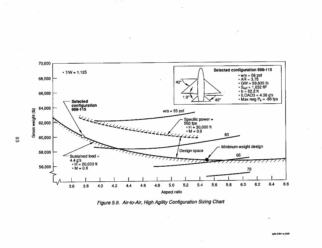
70,000
¢.OCO
A
v
1=._m
u)u)2(.9
68,000
66,000
64,000
62,000
60,000
58,000
56,000
/_ Selected cOnfolguratlon988-115• T/W = 1.125 I / , w/s = 58psf
-- 40o_ /I I'_ AR = 3.75/ J [ _ .GW=59,8351b
.,7E I I _ • Sref = 1,032 ft2__ ,/ • I J _ "b=62.2ft
-1.9oX/_ _,, j___ .ILOAD3=4.38g's"_ Y _ / "_40 ° • Max neg Ps = -60 fps
E'-- Selected_ \ configuration
\ _'/_._ /- Specific power ="-'_ \ ,-(,._-. / 550 fps
• _ \ _'/"_,.Z'.Z._Z . . / • H = 30,000 ft"_'_ _"/_/--Z..E,Z_/.(./../__)// ... • i = 0.9 _n
_ - _ _.,.r../..(,/_
/ -- " _ _ ___ . /- Minimum weight design_ / - / _ / Design space /
Sustained load --
4;4 ig'SH= 20,000 ft° M = 0.6 70
<_I I I I I I I I I I --I I I I I
M 3.6 3.8 4.0 4.2 4.4 4.6 4.8 5.0 5.2 5.4 5.6 5.8 6.0 6.2 6.4 }.6
Aspect ratio
Figure 5.9. Air-to-Air, High Agility Configuration Sizing Chart
spb-5/g4-re-Ad8
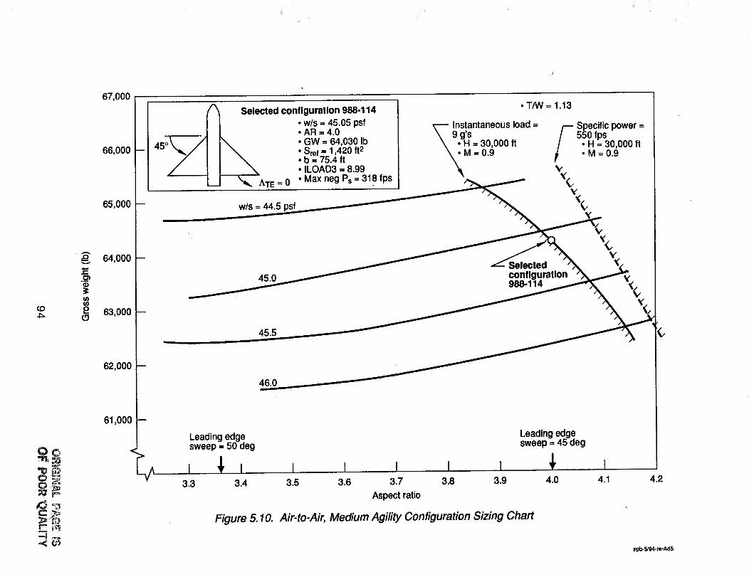
67,000
¢.OJ:=
O©
A.Q
¢0¢/3
2
66,000
65,000
64,000
63,000
62,000
61,000
A Selected configuration 988-114• w/s = 45.05 psf• AR = 4.0• GW = 64,030 Ib
Sref -- 1,420 ft2b = 75.4 ft• ILOAD3 = 8.99• Max neg Ps = 318 fps
w/s = 44.5
45.0
• T/W = 1.13
_. Mlnstantaneousload =9 g's
• H = 30,000 ft
= 0.9
F Specific power =
550 fps• H = 30,000 ft.M=0.9
V
V
Selectedconfiguration988-114
45.5
46.0
Leading edgesweep = 50 deg
3.3 3.4
Figure 5.10.
I I I I I3.5 3.6 3.7 3.8 3.9
Aspect ratio
Leading edgesweep = 45 deg
4.0 4.1 4.2
Air-to-Air, Medium Agility Configuration Sizing Chart
spb-5/94-re*Ad5
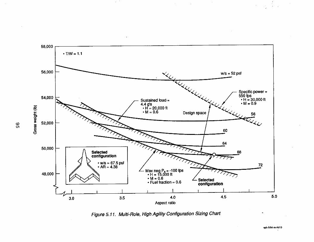
58,000
• T/W= 1.1
COO1
A
v
E-.g_
2(.9
56,000 -- _ _¢,, w/s = 52 psf
(v'_(, Specific power =
_"_ • H = 30,000 ft54,000 -- 550 fps
.M=0.9
52,000
50,000
48,000
Sustained load =4.4 g's
• H = 20,000 ft• M =0.6 Design space 56
6O
Selected
configurationw/s = 67.5 psf
AR = 4.38
>
___ I i I3.0 3.5
_--- Max neg Ps= -100 fps.H = 15,000 ft
• M =0.6• Fuel fraction = 0.6
i I4.0
Aspect ratio
L_ Selectedconfiguration
I I
64
68
4.5
72
Figure 5.11. Multi-Role, High Agility Configuration Sizing Chart
5.0
spb-5/94-re-Ad10
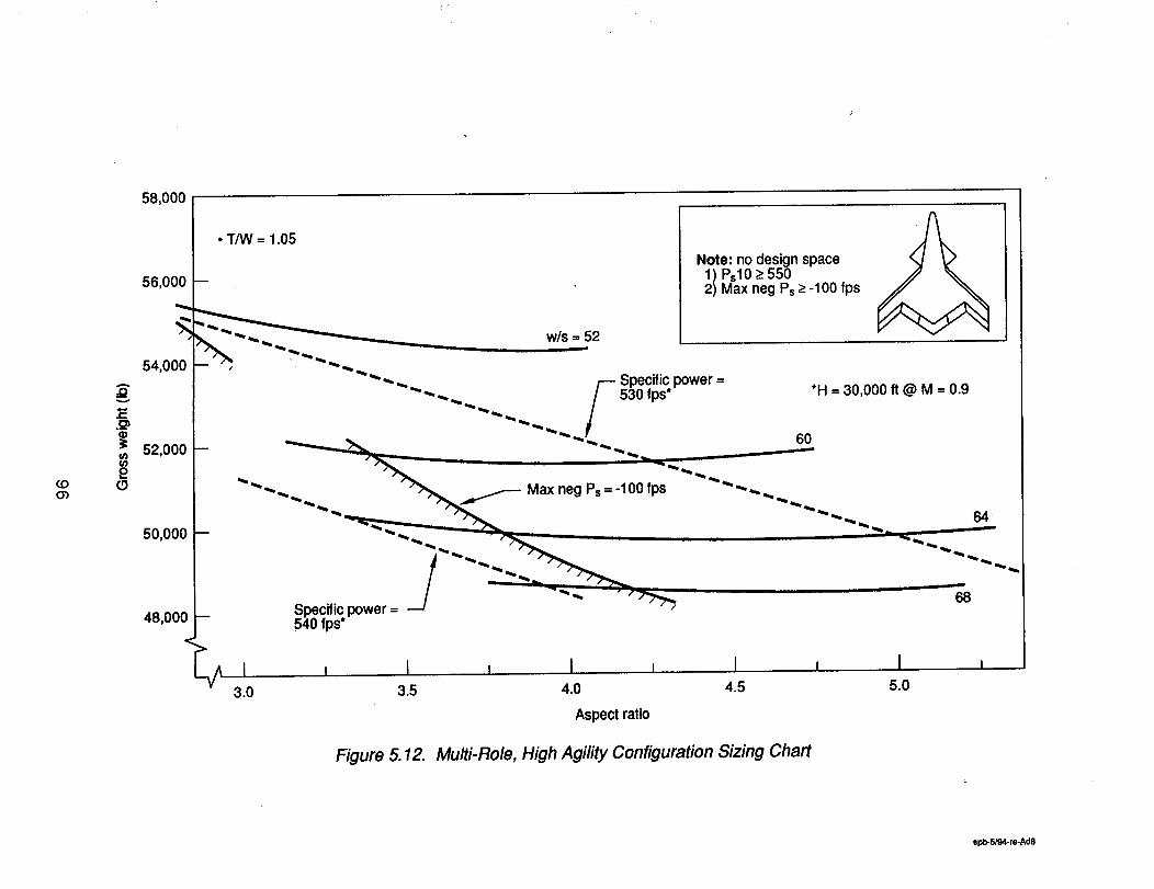
COOb
A.O
(tJf/)2r5
58,000
56,000
• T/W = 1.05 //_.Note: no design space
1) Psl0 >-550-- 2) Max neg Ps ->-100 fps
w/s = 52=,_======w
54.000 " """ "" _ _ .. ,--- Specific power = . .....
"_.... / 530 fps* H = 30.000 ft @ M = 0.9
_ ._ _ 60
52,000 - . _"_ Max neg Ps_ -_00 fps'''''--..'"""
50,000 -- __. ....
, ,ooo- N1" 'p°wer=--/ -'"P
I , i I i , i , I ,"-_ 3.0 3.5 4.0 4.5 5.0
Aspect ratio
Figure 5.12. Multi-Role, High Agility Configuration Sizing Chart
spb-6/94-re-Ad8
To illustrate how the design space disappears at lower thrust levels, another sizing chart wasconstructed using a thrust-to-weight ratio of 1.05. Note how specific power constraint of 550 fpsmoves to lower gross weight designs and no design space remains.
Medium Agility
The variation of aircraft gross weight with the significant design parameters and design constraintboundaries is illustrated on the configuration sizing chart on figure 5.13. The chart was constructedwith a thrust-to-weight ratio of 1.1 which allows a small design space between the instantaneous loadconstraint of 9 g's (M = 30,000 tt at M = 0.9) and the specificpower constraint of 550 fps (H = 30,000 ftat M = 0.9). The other twenty-four constraints are all satisfied. The selected configuration lies on theinstantaneous load constraint of 9 g's at an aspect ratio of 3.6. A slightweight reduction is indicated athigher aspect ratios but there is a concern for flutter. Characteristicsof this design are:
Wing loading = 51.5 psfAspectratio = 3.6Span = 62.6 ft.Leading edge sweep = 38 deg.Gross weight = 56,060 lb.
5.2.4 Joint Service Customer
The original intention for showing the impact of customer on the aircraft designs was a two stageapproach. The firststage was to fix the aircraft missionand maneuver performance capability and thengrow the aircraft structurally until it met the structural requirements of a joint service customer. Thesecond stage would then address the impact of carder suitability, such as Launch and Recovery wind-over deck on aircraft size.
The result of the first stage structural growth is shown in Figure 5.14. This figure is a complete side byside comparison of the Air Force and Joint Service Design Weight Breakdowns enforcing thecondition that both aircraft have the same mission and maneuver performance. In general thestructural penalties associated with carrier suitability increased the aircraft empty weights 14 to 17percent and the design takeoff gross weights 11 to 15 percent.
The span of wing panels outboard of the wing fold range from 17 to 25 feet making them difficult tohandle below deck. All the designs except the multi-role designs exceed the 54,500 lb. zeropayload/maximum fuel weight corresponding to the elevator limit required for efficient flightoperations.
The Joint Service Air Interdiction Design already exceeds the 80,000 lb. launch weight of the A-3,largest aircraft to ever operate from an aircraftcarrier.
Increasing the aircraft size further in response to launch, recovery, and single-engine rate-of-climbrequirements is not a feasible approach. Instead, the 54,500 lb. elevator limit was used to define themaximum launch weight of the Joint Service Designs. The basis of comparing the Joint Servicedesigns with their Air Force counterpartswill be missionradius and maneuver performance.
97
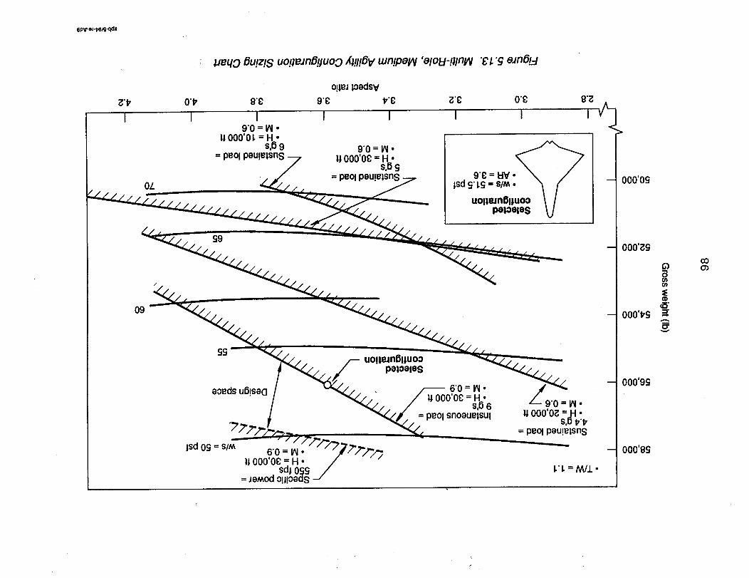
6pweJ._R_e
I
OL
,ueqo 6u!z!s uopeJnB!tuoo Xi!I!6V mn!pei/v 'elol:t-!llnl/V "_'1."9 eJn6!_,-!
o!leJloedsv
O't_ 9"g 9"g t,'g g'g O'g
I I I I I I9"0 = IN •
P,000'01. = H •S,69
= peol peu!elsns9"0 = IN •
11000'Og =liB"S= peol peu!e|sns
$9
O00'OS
O00'gg
Q
o)o)
(I)
000'1_gCT
000'9S
000'8g
CO0")
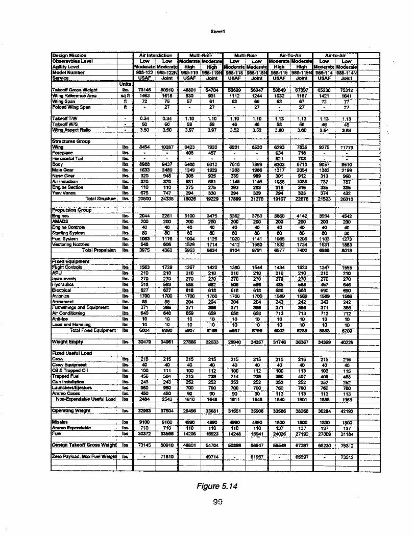
Shee.
DeSkln MissionObseravbles Level
Agility LevelModel NumberService
Takeoff Gross WeightWing Reference Area
Air Interdiction Multi-Role Multi-Role Air-To-Air Air-to-Air
Low Low Moderate Moderate Low Low Moderate IModerat( Low Low
Moderate Moderate Hio_h High Moderate Moderate HicJh High Moderate Moderate988-122 958-122N 988-119 988-1191_ 988-116 958-118N 988-115 1988-115t_ 988-114 988-114_
USAF Joint USAF Joint USAF Joint USAF Joint USAF Joint
UnitsIbs 73145 80910 48801 54704 50899 56947 59549 67397 65230 75312 _
sqft 1463 1618 830 931 1112 1244 1032 1167 1421 1641tt 72 75 57 61 63 65 53 67 72 77
fl 27 - 27 27 27 27Wing SpanFolded Wing Span
Takneff TNV 0.34 0.34 1.10 1.10 1.10 1.10 1.13 1.13 1.13 1.13Takeoff W/S 50 50 59 59 46 46 59 58 45 46
Wing Aspect Ratio 3.50 3.50 3.97 3.97 3.52 3.52 3.80 3.80 3.64 3.64
structuresGroupWingForeplaneHmizim_l Tail
BodyMain Gear
Nose GearAir Induction
Engine SectionYaw Vanes
Ibs 8454 10287 5423 7920 6931 9530 6293 7835 9275 11779Ibs 406 457 634 718
Ibs - 621 7O3Ibs 8988 9437 6488 6512 7618 7999 8303 8718 9057 9510
Ibs 1633 2489 1249 1929 1288 1956 1317 2054 1382 2199Ibs 320 948 306 925 330 989 301 912 313 968
Ibs 320 320 581 581 1145 1145 1088 1088 787 787
Ibs 110 110 275 275 293 293 316 316 335 335Ibs 675 747 294 330 294 329 294 333 374 432
Total Structure Ibs 20500 24338 16026 19229 17899 21270 19167 22676 21523 26010
Propulsion GroupEngines Ibs 2044 2261 3100 3475 3352 3750 3660 4142 3934 4542AMADS Ibs 200 200 200 200 200 200 200 200 200 200
Engine Controls Ibs 40 40 40 40 40 40 40 40 40 40Starl_ System Ibs 80 80 80 80 80 80 80 80 80 80
Fuel System Ibs 1063 1176 1004 1125 1020 1141 1065 1205 1103 1273Vectoring Noz:des Ibs 548 606 1529 1714 1412 1580 1532 1734 1631 1883
Total Propulsion Ibs 3975 4363 5953 6634 6104 6791 6577 7402 6988 5019
Fixed Equipmentmight_APU Ibs
Ine_rumenls Ilos
Hydraulics IbsElectrical Ibs
Avionics IbsArmament Ibs
Furnishings and Equipment Ibs
Air Conditioning IbsAnt_=e U3s
Load and Handling Ibs
Total Fixed Equipment Ibs
1563 1729 1267 1420 1380 1544 1434 1623 1347 1555
210 210 210 210 210 210 210 210 .210 210270 270 270 270 270 270 270 270 270 270518 593 588 682 506 586 485 568 457 546
527 627 618 618 618 618 688 688 690 6901700 1700 1700 1700 1700 1700 1569 1569 1569 1569
85 85 204 204 204 204 242 242 242 242371 386 371 386 371 386 371 386 371 386
640 640 659 659 658 658 713 713 712 71210 10 10 10 10 10 10 10 10 1010 10 10 10 10 10 10 10 10 10
6004 6260 5907 6169 5937 6195 6002 6289 5888 6200
We_t r=lq_ Ibs 30479 34961 27886 32033 29940 34257 31746 36367 34399 40229
Rxed Useful Load
Crew Ibs 215 215 215 215 215 216 215 215 215 215
Craw Equipment Ibs 40 40 40 40 40 40 40 40 40 40
Oil & Trappad Off Ibs 100 111 100 112 100 112 100 113 100 115Trapped Fuel Ibs 456 504 213 239 214 239 360 407 405 468Gun Installat_ Ibs 243 243 252 252 252 252 262 252 252 252
Launchem/E)ectm_ Ib¢,, 980 980 700 700 700 700 760 760 760 760Ammo Cases Ibs 450 450 90 50 50 90 113 113 113 113
Non-Expendable Useful Load Ibs 2484 2543 1610 1648 1611 1648 1840 1901 1685 1963
Operating Wekjnt Ibs 32963 37504 29496 33681 31551 35906 33586 38268 36284 42162
Missies Ibs 9100 9100 4990 4990 4990 4990 1800 1800 1800 1800
Ammo Expandable Ibs 710 710 110 110 110 110 137 137 137 137Fuel Ibs 30372 33596 14205 16023 14246 15941 24026 27192 27009 31164
Design Takeoff Gross Wei_lhl Ibs 73145 80910 48801 54704 50899 56947 59549 67397 95230 75312
Zero Payload, Max Fuel Weight Ibs 71810 - 49714 51957 65597 73512
Figure 5.14
99
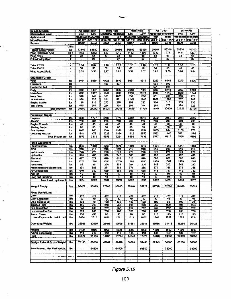
Sheet1
Design Mission IObseravbies Level I_t Wt.eval
NumberService
Units
Takeo_ Gross Weight IbsWing Reference Area SClR
Wm9 Span flFolded Wing Span ft
TakeoffTNVTakeoff W/S
w_ _ Ratio
Stxuctures Groupw_ r_Foreplane insHoriziontal Tail Ibs
BoW ,_Main Gear IbsNose Gear IbsAir Induction Ibs
En_line SecOon IbsYaw Vanes Ibs
Total Stmotum Ibs
Propulsion GroupF_.ng_es _osAMADS Ibs
Engine Controls Ibssta_n9system msFualSystem insVectoring Nozzles Ibs
Total Propulsion Ibs
Fixed EquipmentFr_htContro_ IbsAPU I_.Instruments Ibs
Hydraulics IbsElsctdcal insAvionics insArmament Ibs
Fumlshlngs and Equipment IbsAir Conditionin_l Ib_Anti-loe Ibs
Load and Handfin_l IbsTotal Fixed Equipment Ibs
We_ht_
Air Interdict_m Multi-Role MulU.Role Air-To-Air Air.to-AirLow Low Moderate Moderate Low Low _moderate Moderall Low Low
Modend_ Moderatu High HkJh Moderate Wlodera_ High High ,Moderate Moderate988-122 988-122h 988-119 988-1191_ 988-118 988-1181_ 988-115 988-1151_ 988-114 988-114N
Joint I._ Joint _ Joint U_ Joint U_ ,Joint
73145 63600 48801 59490 50899 59490 59549 56300 65230 563001463 1272 830 1012 1112 1300 1032 975 1421 1227
72 67 57 63 63 68 63 61 72 67
27 27 27 27 27
0.34 0.34 1.10 1.10 1.10 1.10 1.13 1.13 1.13 1.1350 50 59 59 46 46 58 58 46 46
3.50 3.50 3.97 3.97 3.52 3.52 3.80 3.80 3.64 3.64
8454 8086 6423 8613 6931 8911 6293 6545 9275 8806408 497 634 599
621 587
8988 9437 6488 6812 7618 7999 ,8303 8718 9057 95101633 1957 1249 2098 1288 2074 1317 1716 1382 1644320 745 308 1005 330 1033 301 762 313 723
320 320 581 581 1145 1145 1088 1088 787 787110 110 275 275 293 293 316 316 335 335675 587 294 358 294 344 294 278 374 323
20500 21242 16026 20241 17899 21799 19167 20609 21523 22128
2044 1777 3100 3779 3352 3918 3660 3460 3934 3395200 200 200 200 200 200 200 200 200 20040 40 40 40 40 40 40 40 40 4080 80 80 80 80 80 80 80 80 80
1063 740 1004 1328 1020 1251 1065 884 1103 773548 476 1529 1864 1412 1650 1532 1448 1631 1408
3975 3314 5.953 7291 6104 7139 6577 6113 6988 5896
1563 1359 1267 1545 1380 1613 1434 1356 1347 1163210 210 210 210 210 210 210 210 210 210270 270 270 270 270 270 270 270 270 270
518 466 588 742 506 612 485 475 457 408627 627 618 618 618 618 688 688 690 690
1700 1700 1700 1700 1700 1700 1569 1569 1569 156985 85 204 204 204 204 242 242 242 242371 386 371 386 371 386 371 386 371 386
640 640 659 659 658 658 713 713 712 71210 10 10 10 10 10 10 10 10 1010 10 10 10 10 10 10 10 10 10
6004 5763 5907 6353 5937 6291 6002 5928 5888 5670
Ibs 30479 30319 27886 33885 29940 35229 31740 32651 34399 33694
F'med Useful LoadCrew Ibs
Crew Equipmem insOil & Trapped Oil insTrapped Fuel IbsGun Installation Ibs
Launchers/Ejectors IbsAmino Cases lbs
Non-Expendable Useful Load Ibs
ope,_ng We_ht
215 215 215 215 215 215 215 215 215 21540 40 40 40 40 40 40 40 40 40
100 70 100 132 100 123 100 83 100 70456 318 213 282 214 263 360 299 405 284243 243 252 252 252 252 252 252 252 252
980 980 700 700 700 700 760 760 760 760450 450 90 90 90 90 113 113 113 113
2484 2315 1610 1711 1611 1682 1840 1762 1885 1734
Ibs 32963 32635 29496 35596 31551 36911 33586 34413 36284 35428
Missies Ibs
Amino Expendable Ibs_uel Ibs
Design Takeoff Gross Weight Ibs
Zero Payload, Max Fuel Weight Ibs
9100 9100 4990 4990 4990 4990 1800 1800 1800 1800710 710 110 110 110 110 137 137 137 137
30372 21155 14205 18794 14248 17479 24026 19950 27009 18935
73145 63600 48801 59490 50899 59490 59549 56300 65230 56300
54500 54500 54500 54500 54500
Figure 5.15
100
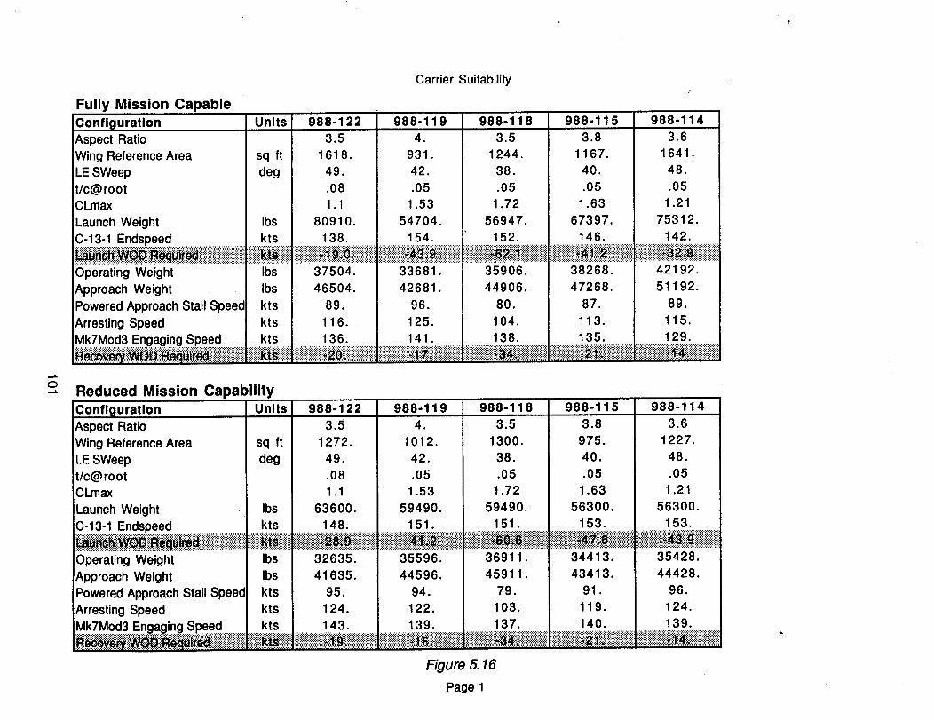
Fully Mission Capable
ConfiQuration UnitsAspect RatioWing Reference Area sq ft
LE SWeep degt/c@rootCl_max
Launch Weight Ibs
C-13-1 Endspeed kts
Operating Weight Ibs
Approach Weight Ibs
Powered Approach Stall Speed kts
Arresting Speed kts
Mk7Mod3 Engaging Speed kts
o bility--" Reduced Mission Capa
Carrier Suitability
988-122 988-119 988-118 988-115 988-114
3.5 4. 3.5
1618. 931. 1244.
49. 42. 38.
.08 .05 .05
1.1 1.53 1.72
80910. 54704. 56947.
138. 154. 152.
37504. 33681. 35906.
46504. 42681. 44906.
89. 96. 80.
116. 125. 104.
I 136 141. 138.iiii!!i!ii !i!i i iii i i!i i!!ii!i i iiiiiiiiiiiiiiiiiii}iii i iiiiiiiiiiiii
Confi_luration Units 988-122 988-119 988-11 8Aspect Ratio 3.5 4. 3.5
Wing Reference Area sq ft 1272. 1012. 1300.
LE SWeep deg 49. 42. 38.t/c@root .08 .05 .05CLmax 1.1 1.53 1.72
Launch Weight Ibs 63600. 59490. 59490.
C-13-1 Endspeed kts 148. 151. 151.
Operating Weight Ibs 32635. 35596. 36911.
Approach Weight Ibs 41635. 44596. 45911.
Powered Approach Stall Speed kts 95. 94. 79.
Arresting Speed kts 124. 122. 103.
Mk7Mod3 Engaging Speed kts 143. .............13:9;:.............. 137.=_._:i::;iii=:::.:._iiiii::ii:.._:=_i::_i_i::i!:._::::::!ii:i.:_:::::::iiiiii_iiiiiiii__i_i_iii!ili;iili!iiiil..........................................
Figure_16
Page 1
3.8
1167.
40.
.05
1.63
67397.
146.::::::::::::::::::::::::::::::::::::::::::::::::::::::::::::::::::::::::::
38268.
47268.
87.
113.
135.
::::::::::::::::::::::::::::::::::::::::::::::::::::::::::::::
988-115
3.8
975.40.
.051.63
56300.
153.
-..- ........... ..._..... ._.. ........ _.,
34413.
43413.
91.
119.
140.:::::::::::::::::::::::::::::::::::::::::::::::::::::::::::::::::::::::::
"!'!'!'!'!'!'!'!'!'!'!_'!'_; .! !:i:i!!!!!!!!!!ii_
3.6
1641.
48.
.05
1.21
75312.
142.
42192.
51192.
89.
115.129.
i!iiiiiiiiiiii ii ! i ii!iiiiii!iiiiiii!iiiiii
988-114
3.6
1227.
48.
.05
1.21
56300.
153.
35428.
44428.
96.
124.
139.
(},0 Confiouration and Performance Results
Joint Service Usage
Configuration Issues
The general arrangements of each USAF concept for Models 988-115, -118, and -122/-123 embodybasic features that permit incorporation of Joint Service unique items without voiding the design.These major unique items consist of carder landing gear, arresting hook, and wing fold. Performancepeculiar and mission resizing for zero fuel weight growth will impact size as a function of visibilityrequired, and mission fuel increases required to perform the mission.
USAF Service
Air Interdiction Concept
Conflauration Descdotion
The vehicle type is stipulated as a low observable configuration for both the medium and high agilityperformance conditions, Sizing iterations resulted in a decision to represent both vehicle types inone configuration arrangement with the only principal differences being engine thrust level andmission fuel required.
This vehicle, Model 988-122/-123, is a single-place, subsonic all flying wing design powered by twinlow bypass engines of 13,865 pounds dry thrust each. Externally, the vehicle, shown in generalarrangement drawing ASC988-122-1, is characterized by the moderately swept leading edge at 48.75degrees, lower surface inlet apertures, full span trailing edge elevons, and upper surface thrustvectoring exhaust nozzles. The wing leading edge incorporates large powered slats that are used toachieve critical maneuver conditions.
Control effectors include the yaw thrust vectoring exhaust nozzles with +45 degrees of deflection,upper and low Yaw Vane pairs integrated with the nozzle and lower surface, and four elevons persemi-span. Elevons are single panel at the most outboard and inboard position, with the two mid-spanpanels being split on the wing reference plane.
The interior layout, shown on inboard profile drawing ASC 988-122-2, provides sufficient room for allfunctional systems and features required. Principal features are the deep (approximately 15% t/c)center section for weapons bay, fuel tankage, crew station and equipment installations, include 30mmgun system installation. Basic thickness ratio decreases to approximately 8.5% at the main landinggear and then to 5% in the outboard panel.
The propulsion installation occupies a bay full chord length for each engine. The inlet is pitot typewith a slightly offset diffuser duct.
Exhaust system features for the non-augmented engine consist of the fully offset duct turningthrough a circular bearing/rotation plane to direct exhaust gas through the rotating nozzle exit plane.The exhaust nozzle is a fixed throat SERN type that utilizes the inboard upper surface as anexpansion surface.
Fuel tankage in the outer wing panel is integral. Center section fuel tankage above the weapons bayhas main tank volume allocated as bladder protected "get-home" fuel.
102
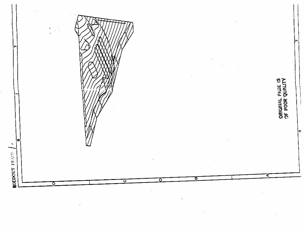
U

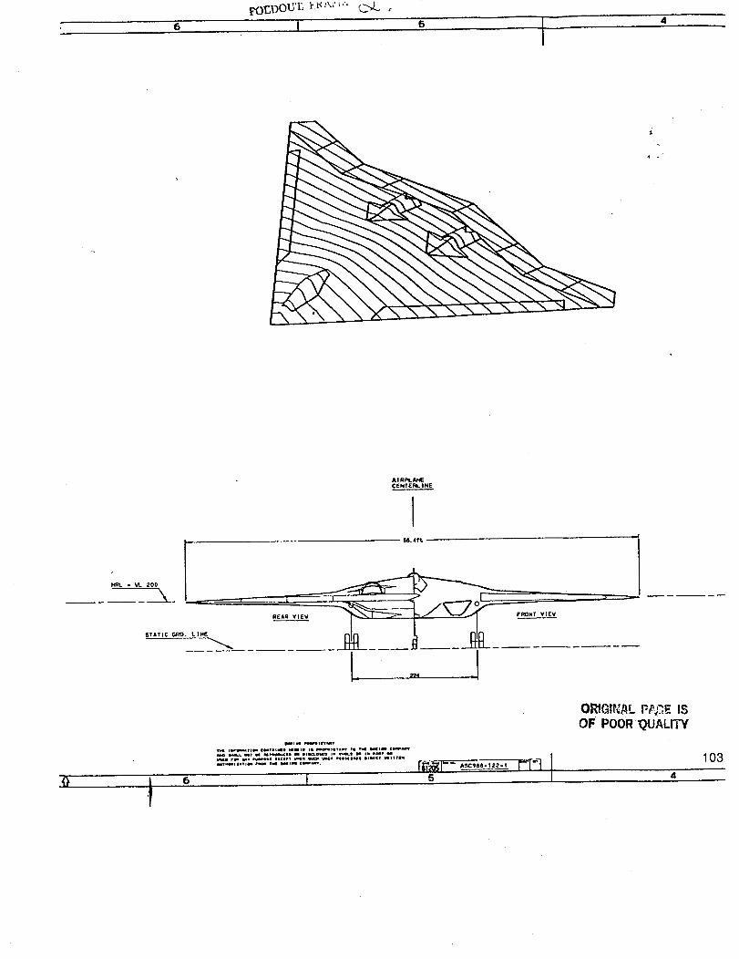
6 I
%,
A I Rl:q. Able
CENTEI_. |NE
ISTATIC GRO. L)NE
@)4).4 ft
2)24 --
O_GIP,:._L FP,_GE IS
OF POOR'QUALITY
6
n _v
i =v) _ )
I_"s """'"" r-t-i]
103

-IT
STA
O. 0__0
99

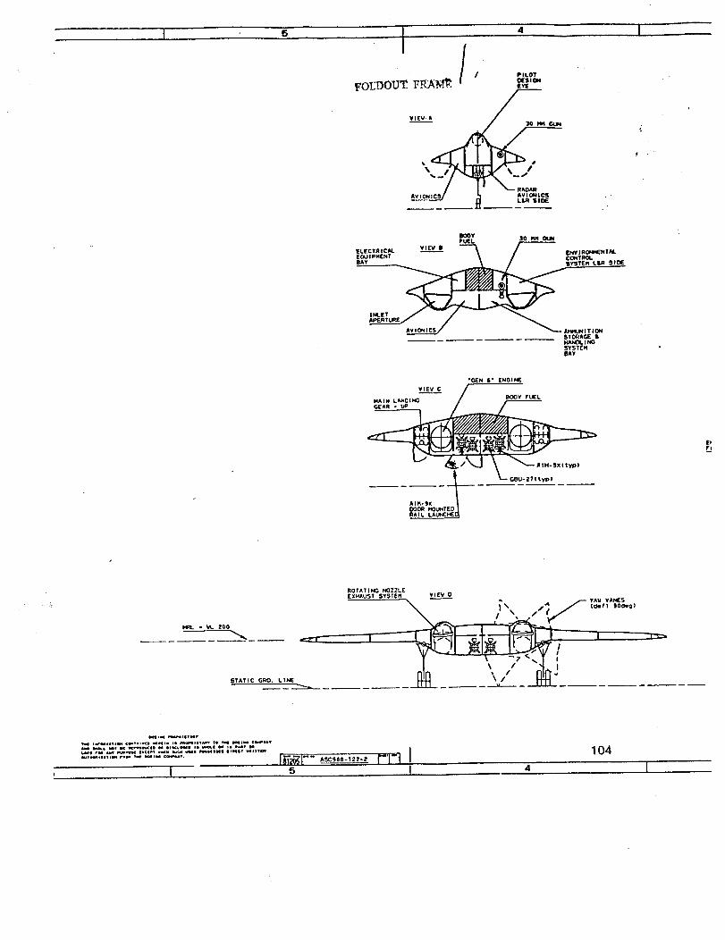
I 5 I
/ / PILOT
FOL'I_OUT F_A -N_._,! t_'_s'_
+;
.+
BOOT 30 _FUEl
ELECTRIC/U. Vl_ I _ / EHV I RONI4ENTAL
SYSTEM b& R SI_
INLETAPERTURF"
ST_Ar.F •
SYSTEMBAY
"GEN 6" [NOINE
VI[W C /
Z+/_ I \ _ I. x ,l t_
GBU-2?I typi
/
RAIL LAUNCHEC_
STATIC GRO. LINE
ROTAT I N( _ NOZZLEEXHAUST SYSTEM ¥1_ 0
A +',,,"
= •
Ju,..l_,l, o,,• im tree I_I =+ C_,_.a• i • i .v,
I[_1-'+ ,+¢-,-,--+. P'l'] I
104
4 I

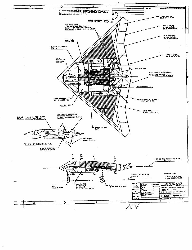
141S0 IDe
A p_.. C _.. ..(._rZONT/U_ KEFEmENC[ L.I_
I"' r" I'" r"
Z _% 200 Y
L

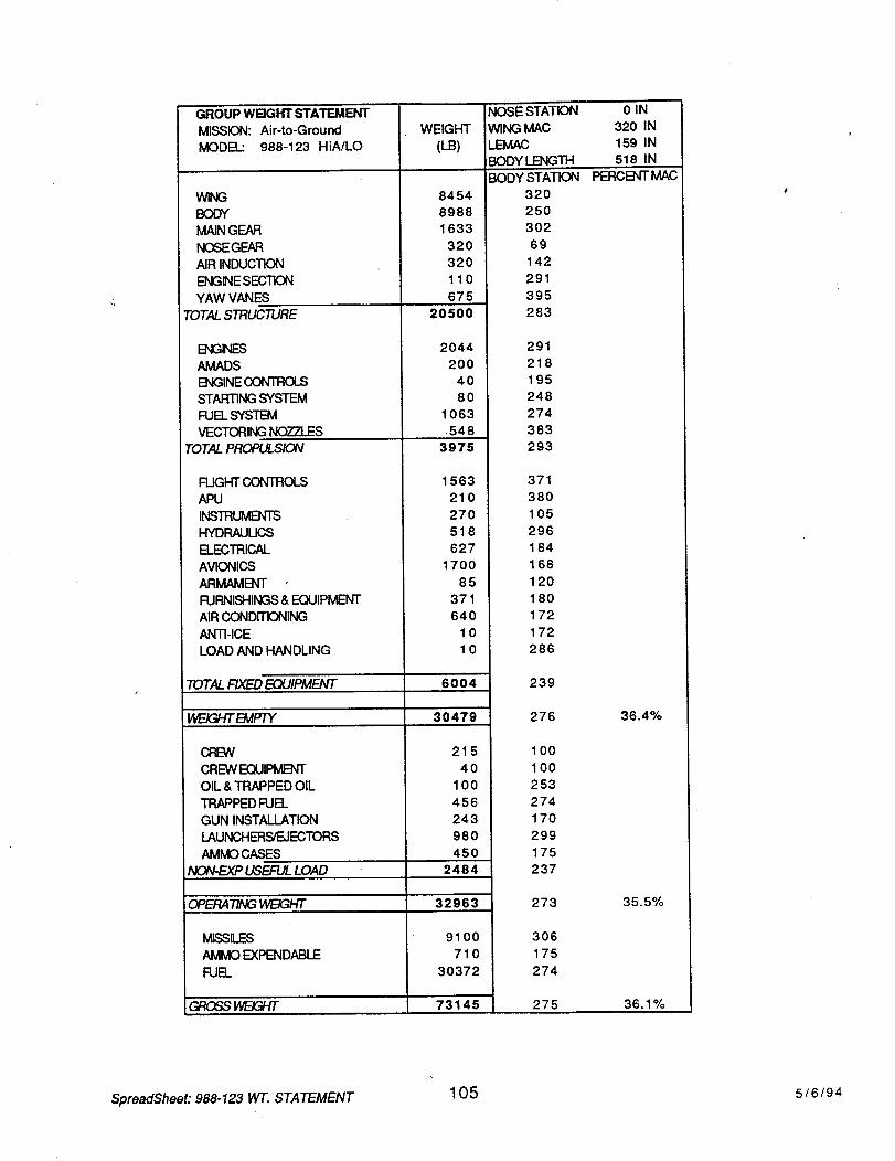
GROUP WBGHT STATEMENT
MISSION: Air-to-Ground
MODEL: 988-123 HiAJLO
W_G
BODY
MAIN GEAR
NOSEGEAR
AIR INDUCTION
ENGINE SECTION
YAW VANES
TOTAL STRUCTURE
E]_31_ES
AMADS
ENGINE CONTROLS
STARTING SYSTEM
FUEL SYSTEM
VECTORING NOZZLES
TOTAL PROPULSION
FUGHT CONTROLS
APU
INSTRUMENTS
HYDRAULICS
ELECTRICAL
AVIONICS
ARMAME]_T
FURNISHINGS & EQUIPMENT
AIR CONDITIONING
ANTI-ICE
LOAD AND HANDLING
TOTAL FIXED EQUIPMENT
WE_d-fTBWPTY
CREW
CREW EQUIPMENT
OIL & TRAPPED OIL
TRAPPED FUEL
GUN INSTALLATION
LAUNCHERS/EJECTORS
AMMO CASES
NON-EXP USEFUL LOAD
WEIGHT
(LB)
8454
8988
1633
320
320
110
675
20500
2044
200
40
80
1063
548
3975
1563
210
270
518
627
1700
85
371
640
10
10
6004
30479
215
4O
100
456
243
980
450
2484
OPF_F_NGW/_3/-r/" 32963
M_SLES
AMMO EXPENDABLE
FUEL
9100
710
30372
GROSS _ 73145
NOSESTATION
_NGMAC
LEMAC
_DYLENG_
0IN
320 IN
159 IN
518 IN
BODY STATION
320
250
302
69
142
291
395
283
PERCENT MAC
291
218
195
248
274
383
293
371
380
105
296
184
168
120
180
172
172
286
239
276 36.4%
100
100
253
274
170
299
175
237
273 35.5%
306
175
274
275 36.1%
SpreadSheet: 988-123 W'l-. STATEMENT105 5/6/94
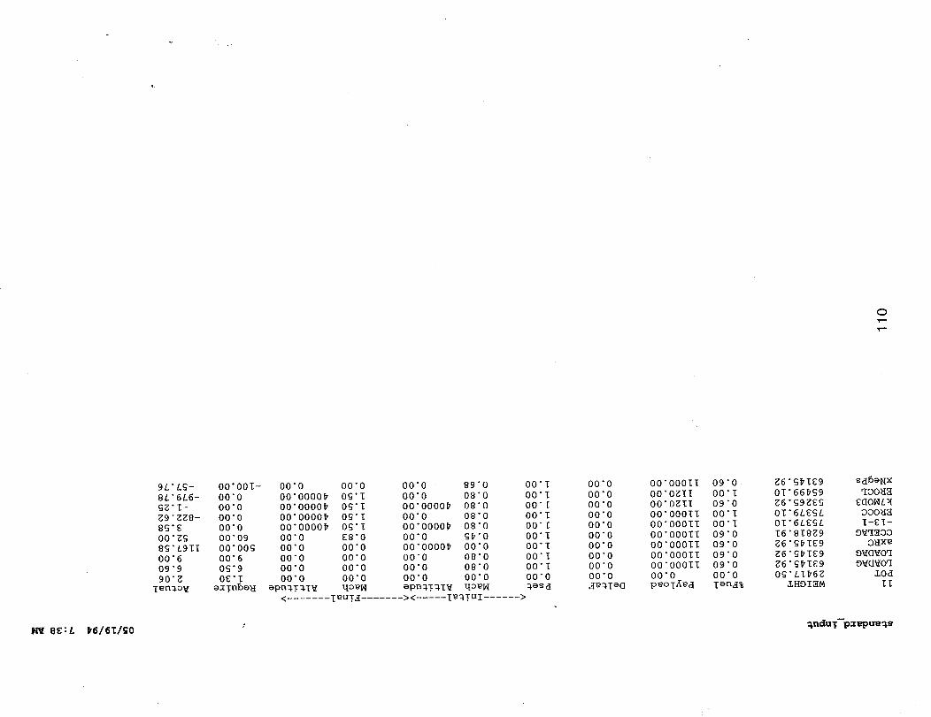
C)
8E:L _6/61/_0
9L'LG- O0"OOI- 00"0 00"0
8L'6L6- 00"0 00"0000_ OG'I
_g'I- 00"0 00"0000_ O_'I
_9"gg8- 00"0 00"0000_ O_'I
8_'E 00"0 00"0000_ 0_'I
O0"g_ 00"09 00"0 ES"O
8_'L911 00"00_ 00"0 00"0
00"6 00"6 00"0 00"0
09"9 0_'9 00"0 00"0
90"_ OE'I 00"0 00"0
i_n_ov a_!nb_ _ _pn_T_IV qo_H
00"0 89"0
00"0 08"0
00"0000_ 08"0
00"0 08"0
00"0000_ 08"0
00"0 _'0
00"0000_ 00"0
00"0 08"0
00"0 08"0
00"0 00"0
_pn_!_T V qo_
00"I
00"I
00"I
00"I
00 I
00 I
00 1
00 1
00 1
00 0
< ....... leu!_ ....... >< ..... i_qIuI ...... >
00"0 00"000II 09"0
00"0 00"0gII 00"I
00"0 00"0gII 09"0
00"0 00"000II 00"I
00"0 O0"O00II 00"I
00"0 00"00011 09"0
00"0 O0"O001I 09"0
00"0 00"00011 09"0
00"0 O0"O00II 09"0
00"0 00"0 00"0
_%I_G p_oT_d I_n_%
_6"G_IE9
01"66_G9
_6"G9gEg
OI'6LEGL
OI'6LEGL
16"81899
g6"G_IE9
O_'tI_6g
LHOI_M
sd6eNX
qOOH_
EQOHL_
OOOH_
I-E1-
O_q_OD
OHXe
O_O_Oq
O_Oq
II
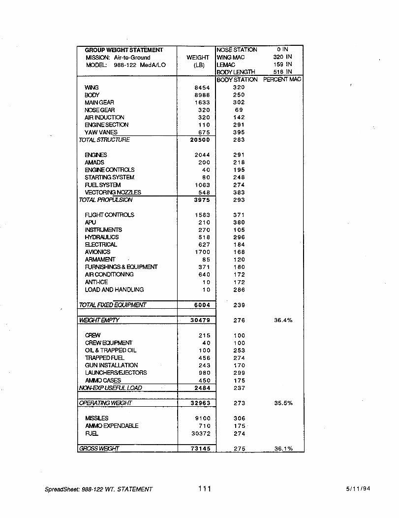
GROUP WEIGHT STATEMENT
MISSION: Air-to-Ground
MODEL: 988-122 MedA/LO
WNG
BODY
MAIN GEAR
NOSEGEAR
AIR INDUCTION
ENGNE SECTION
YAW VANES
TOTAL STRUCTURE
ENGNES
AMADS
WEIGHT
(LB)
8454
8988
1633
320
320
110
675
20500
ENGINE CONTROLS
STARTING SYSTEM
FUEL SYSTEM
VECTORING NOZZLES
TOTAL PROPULSION
FLIGHT CONTROLS
APU
INSTRUMENTS
HYDRAULICS
ELECTRICAL
AVIONICS
ARMAMENT
FURNISHINGS & EQUIPMENT
AIR CONDITIONING
ANTI-ICE
LOAD AND HANDLING
2044
200
40
80
1063
548
3975
1563
210
270
518
627
1700
85
371
640
10
10
TOTALRXEDEQUIPMENT 6004
t4Fc/CV_EMPTY 30479
215
40
100
456
243
980
450
CFEW
CREW EQUIPMENT
OIL & TRAPPED OIL
TRAPPED FUEL
GUN INSTALLATION
LAUNCHERS/EJECTORS
AMMO CASES
NON-F_XP USEFUL LOAD 2484
OPERARNGHFc/GHT 32963
9100
710
30372
MLSSEES
AMMO EXPENDABLE
FUEL
__ 73145
NOSE STATION
WING MAC
LEMAC
BODY LENGTH
BODY STATION
320
250
302
69
142
291
395
283
291
218
195
248
274
383
293
371
38O
105
296
184
168
120
180
172
172
286
239
276
100
100
253
274
170
299
175
237
273
306
175
274
275
0 IN
32O IN
159 IN
518 IN
PERCENT MAC
36.4%
35.5%
36.1%
SpreadSheet: 988-122 WT. STATEMENT 1 1 1 5/1 1/94
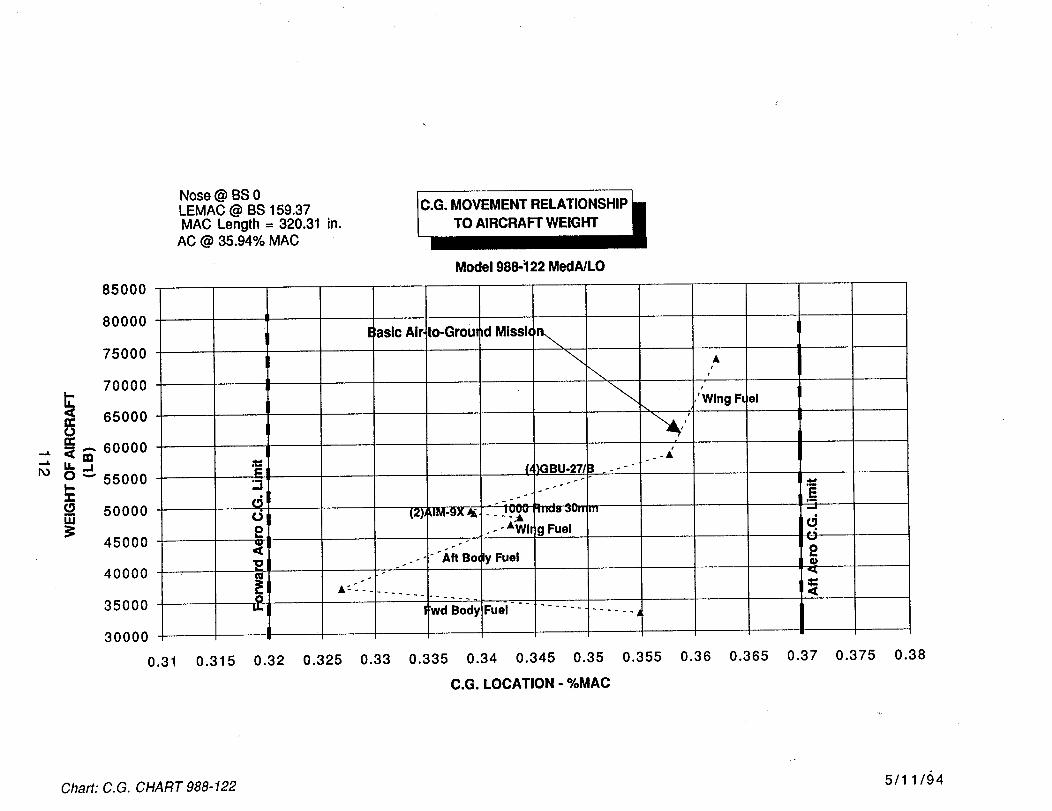
n-On"
I--"l-
uJ
Nose @ BS 0LEMAC @ BS 159.37MAC Length --- 320.31 in.
AC @ 35.94% MAC
Model 988-122 MedAJLO
85000
80000
75000
70000
65000
60000m
55000
50000
45000
40000
350O0
30000
0.31
E;asic Air to-Groul;d Missk)n..._-,.,.
\\ t
'Wing FL el
i
E (,__GBU-27J3 _--"
- ,.o , . - - •Wlr g Fuel
'_ ""Aft Bo, ly Fuel e•,21 ,_
A:_ ".
:wd Body Fuel ....... -I...... j
0.315 0.32 0.325 0.33 0.335 0.34 0.345 0.35 0.355 0.36 0.365 0.37 0.375 0.38
C.G. LOCATION - %MAC
Chart: C.G. CHART 988-122 5/1 1/94
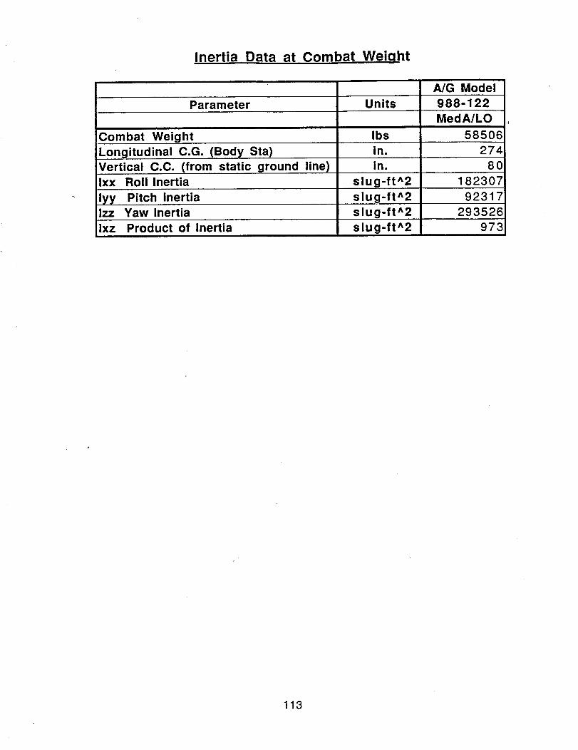
Inertia Data at Combat Weiqht
Parameter
Combat Weight
Longitudinal C.G. (Body Sta)
Vertical C.C. (from static ground line)
Ixx Roll Inertia
lyy Pitch InertiaIzz Yaw Inertia
ixz Product of Inertia
A/G Model
Units 988-122
MedA/LO
Ibs 58506
in. 274
in. 80
slug-ft^2 182307
slug-ft^2 92317
slug-ft^2 293526973slug-ft^2
113
6.2 Air Superiority Concepts
Model 988-115, High Agility - Moderate Observables
The high agility, moderate observables vehicle, Model 988-115, is a single place, three-surfacesupersonic design powered by two turbojet engines of 33,660 pounds augmented thrust e_ch.Externally the vehicle general arrangement, shown on drawing ASC 988-115-1, includes a liftingcanard or foreplane ahead of the main wing and a horizontaltail aft of main wing.
Each surface (wing/canard/tail), is of identical planform with forty (40) degrees leading edge sweep.The canard and tail are identical plan areas and the canard is set at +10 degrees dihedral, with the wingand tail set at -5 degrees relative to the horizontal reference plane.
Inlets are integrated/nested with the lower forebody, inboard of canard deflection path. Exhaustnozzles are located side-by-side on the upper aft fuselage and Yaw Vane pairs are integrated with thenozzles and on the lower aft body.
Control effectors include the yaw thrust vectoring exhaust nozzles, with _+40degrees of deflection,the Yaw Vane pairs above and below aft fuselage, and main wing trailing edge plain flaps, in additiontothe canard and horizontal tail.
Initial sizing optimizations for the high agility metric conditions resulted in main wing size and aspectratio which established overall span at a size that was considered impractical to achieve in a high agilityfighter. The approach taken was to extract the equivalent horizontal tail exposed area from thetheoretical main wing and incorporate a lifting canard/foreplane. This arrangement replicates thatcurrently in use on the F-15/SMTD research vehicle.
The interior layout, shown on inboard profile drawing ASC 988-115-2, accommodates the crew,subsystem, weapons and propulsion system volume allocations within a low profile body shape. Theforebody is conventional in arrangement and includes avionics, crew station, gun system, andavionics subsystem. Center body contents are main fuel tanks, inlet system, weapons bay, and mainlandinggear. The aft body provides engine and exhaust system accommodation.
Propulsion system installation features consist of the nested external compression fixed ramp inlet,long vertical offset inlet diffuser running over the weapons bay to engine face.
The exhaust system includes augmentor spray bars, fully offset duct to nozzle exit plane. The ductturns through a circular bearing/rotation plane to direct exhaust gas out the nozzle aperture. Asignificant and challenging risk issue is presented here in this concept of making the rotating nozzlesystem augmentor capable. A discussion of this issue is contained in Section 7.0, Areas of HighTechnical Risk.
Nozzle concept is that of a variable throat SERN type that utilizes the upper aft deck as the expansionsurface.
Fuel tankage in the main wing panel is integral and center section tankage contains fuel inconventional bladder cells.
114
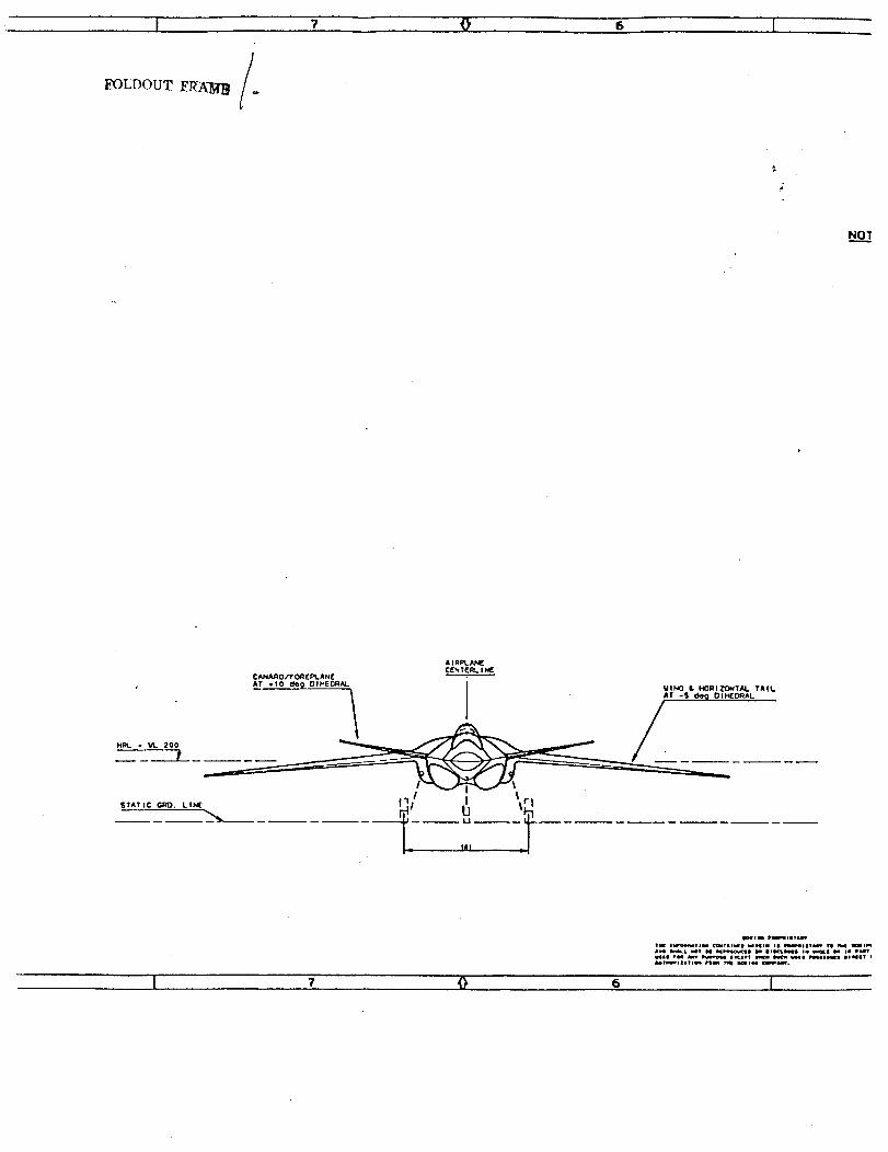
6
AIR_JU_C['q TERL I
CAJ_A.qO/F OR (I:_. AN( i
AT .10 _ DIHE{_I,_I. VINO • HORIZO_IT_M. TAIL
HRL - vl. 200 _ /_ I I _
STMnC _0. LINE I_11 I
,I I'1 d
"=..',--_-_::_."E:'_-_.i'_,"-_',-',",., . -• o
I 7 @ S I

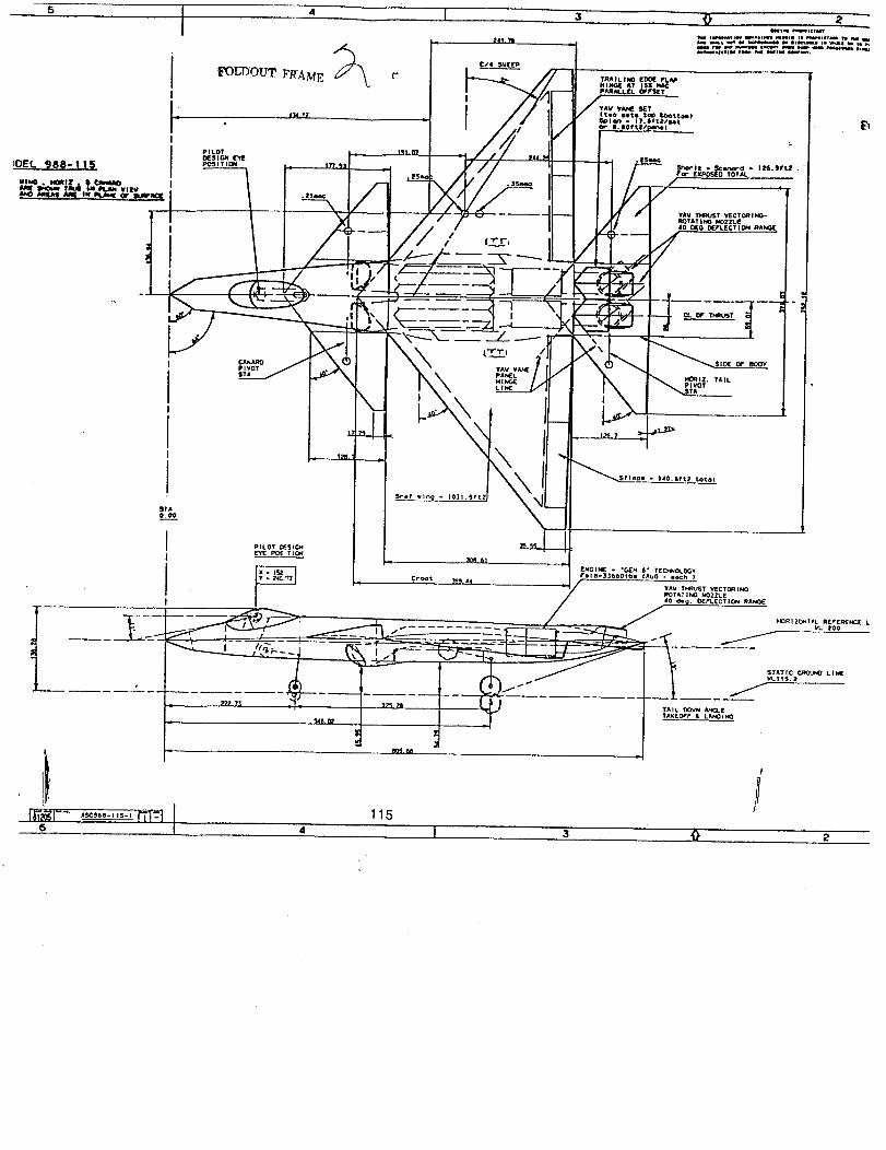
5 43 0 2
STA
0+00
/
30S 61
/It_11 Z. TAlL
i
'++'.....'--- m'J Is I
IPNGINIE . *C_N 6* TEC_WOI.OGY
Fele-3._@@Olbe IAUG each )¢r@¢$ _ 44 "
• " " /--- __+o.,._
...... _ _ _- ZOO L_c_l "---u-7_, , _-_-_ __ __ _ +_-
..L _ t ,.k ../ r ,,,:,,+,,+..+..+L,,.
....+ +:+ ,...o.,,++
115 ]

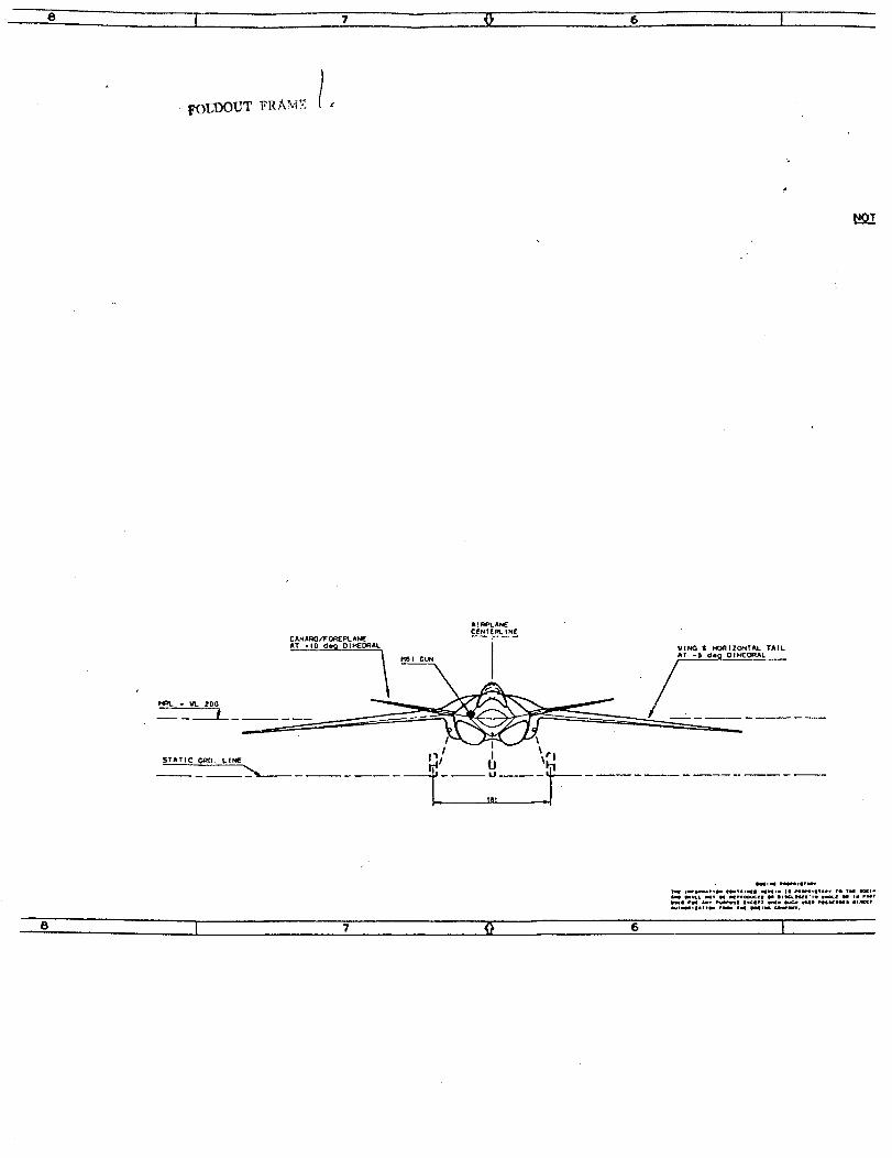
' FOI_DOUT FRA'vi% I,
A ! RPL A_
CENTER_. I NE
CANARO/F 0REPL AN_ i
AT *10 de_ DIHEDRAL VINO • H_IIIZONT_L TAIL
_ - _ 1'00
L •
i. _,_ll r e. • v.I I.N .Q _l_
e I 7 O 6 I

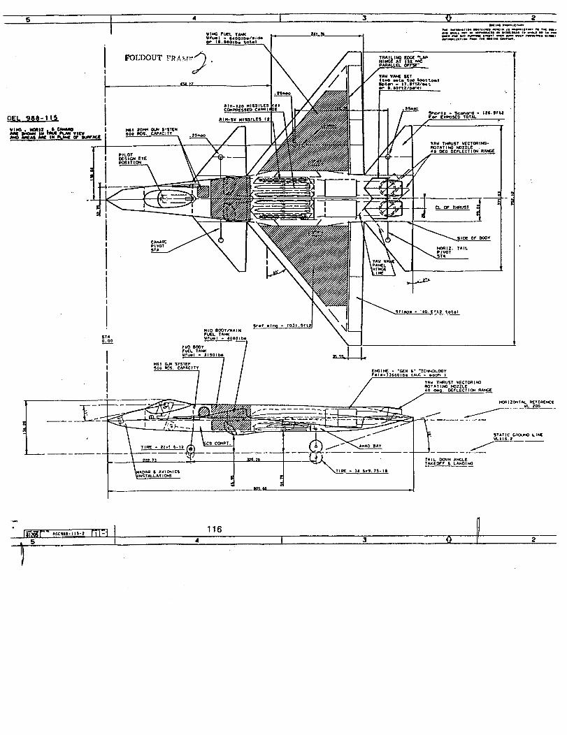
t I
iI
I
II
;4!
2
STA
O.OO
K'_M
5
1


GROUP WPlGHT STAllEMENT
MISSION: Air-to-Air
MODEI_ 988-115 HiA/ModLO
W_GHORIZONTAL TAIL
YAW VANES
BODY
MAIN GEAR
NOSEGEAR
AIR INDUCTION
ENGINE SECTION
FOREPLANE
WEIGHT
(LB)
TOTAL STRUCTURE
E_3NES
AMADS
ENGINEc rmOLSSTARTING SYSTEM
FUEL SYSTEM
VECTORING NOZZLES
TOTAL PROPULSION
FUGHT CONTROLS
6293
621
294
8303
1317
301
1088
316
634
19167
3660
200
40
8O
1065
1532
6577
APU
INSTRUMENTS
HYDRAUUCS
ELECTRICAL
AVIONICS
ARMAMENT
FURNISHINGS & EQUIPMENT
AIR CONDITIONING
ANTI-ICE
LOAD AND HANDLING
TOTAL F/XED EQU/Ph'EgVT
1434
210
270
485
688
1569
242
371
713
10
10
6002
WE/GF/TB_/PTY 31746
215
40
100
360
252
760
113
1840
CFE_N
CREW E(_IPMENT
OIL & TRAPPED OIL
TRAPPED FUEL
GUN INSTALLATION
LAUNCHERS/EJECTORS
CASES
NON-EXP USEFUL LOAD
OPERARNGWE/GHT 33587
1800
137
24026
MISSILES
AMMO EXPENDABLE
FUEL
G_/OSSV___F/T 59550
NOSE STATION
WING MAC
LEMAC
BODY LENGTH
BODY STATION
550
760
705
468
549
212
410
625
312
504
625
550
389
580
504
730
626
585
680
158
587
436
200
228
264
410
120
468
396
509
153
153
590
504
228
460
228
387
502
460
228
504
500
0 IN
242 IN
434 IN
806 IN
PERCENTMAC
30.8%
28.1%
27.4%
SpreadSheet: 988-115 Wt. Statement 1 17 5/6/94
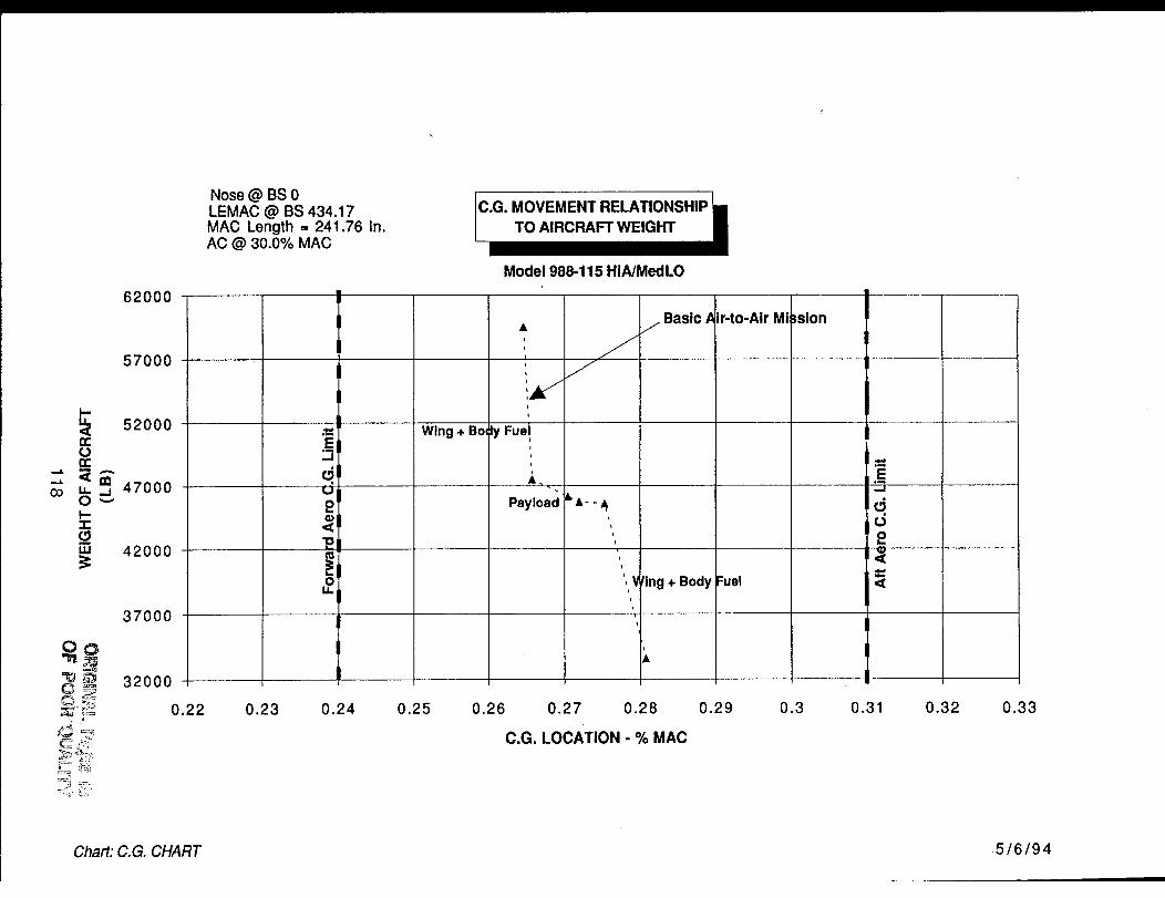
CO
62000
57000
52000
47000
w 42000
37000
QO
q _ 32000
Nose @ BS 0LEMAC @ BS 434.17MAC Length = 241.76 In.AC @ 30.0% MAC
C.G. MOVEMENT
Model 988-115 HIA/Med LO
E'-1d<52
OIJ.
Wing + Bo,
At
t
I
I
I
|y FueJI
=
i
I
I
A,
Payload
/ Basic A
f
&,&- -,&
i
, Vling + BodyL
L
L
Jr-to-Air Mi
;uel
3slon
E
d2<
<
0.22 0.23 0.24 0.25 0.26 0.27 0.28
C.G. LOCATION - % MAC
0.29 0.3 0.31 0.32 0.33
Chart: C.G. CHART 5/6/94
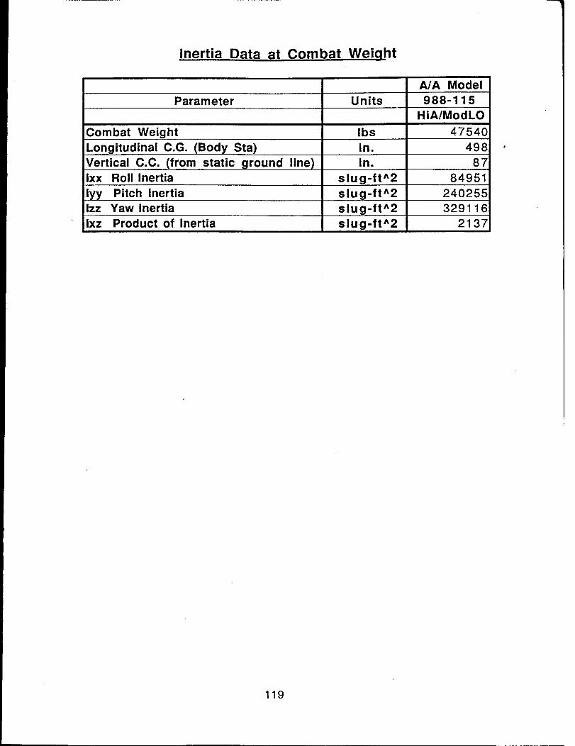
Inertia Data at Combat Weiqht
A/A Model
Parameter Units 988-115
HiA/ModLO
Combat Weight Ibs 47540
in. 498Longitudinal C.G. (Body Sta)
Vertical C.C. (from static ground line)Ixx Roll Inertia
in.
slug-ft^2
87
84951
lyy Pitch Inertia slug-ft^2 240255
Izz Yaw Inertia slug-ft^2 329116
Ixz Product of Inertia slug-ft^2 2137
119
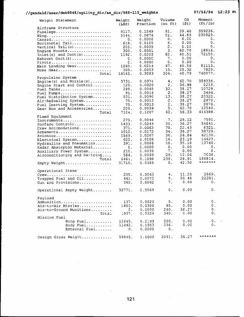
//gandalf/user/deb9848/agility_dir/aa_dir/988 - 115_weight s
Weight Statement Weight(LBS)
Airframe Structure
Fuselage ........................ 9117Wing ............................ 5144Canard .......................... 0Horizontal Tail ................. 618
Vertical Tail(s) ................ 205
Engine Mounts ................... 300Inlet(s) and Duct(s) ............ 1192
Exhaust Duct(s) ................. 0Pivots .......................... 0
Main Landing Gear ............... 1260Nose Gear ....................... 309
Total 18145
Propulsion System
Engine(s) and Nozzle(s) ......... 5731.Engine Start and Control ........ 120.Fuel Tanks ....................... 280.
Fuel Pumps ...................... 91.Fuel Distribution System ........ 531.
Air-Refueling System ............ 75.Fuel Inerting System ............ 75.Gear Box and Accessories ........ 200.
Total 7104.
Fixed EquipmentInstruments ..................... 270.
Surface Controls ................. 1433.
Crew Accomodations .............. 371.Armaments ....................... 1012.
Avionics ........................ 1569.
Electrical System ............... 622.Hydraulics and Pneumatics ....... 391.
Radar Absorpton Material ........ 0.
Auxiliary Power System .......... 210.Airconditioning and De-Icing .... 584.
Total 6461.
Empty Weight .................... 31710.
Operational Items"Crew ............................
Trapped Fuel and Oil ............Gun and Provisions ..............
Operational Empty Weight ........
PayloadAmmunition ......................Air-to-Air Missles ..............
Air-to-Ground Munitions .........
Total
Mission Fuel
Wing Fuel ...........
Body Fuel ...........External Fuel .......
Design Gross Weight .............
WeightFraction
0.1549
0 0874
0 00000 0105
0 00350 0051
0 0203
0 00000 0000
0 02140.00530.3083
0.09740.0020
0.00480.0016
0.0090
0.0013
0.00130.0034
0.1207
0 0046
0 0244
0 00630 0172
0 0267
0 01060 0066
0 0000
0 0036
0.00990.1098
0.5389
255. 0.0043
441. 0.0075
365. 0.0062
32771. 0.5569
Volume
(cuft)
91
510
62
3
827
047
15306.
4.
2.32.
2.
13.2.
2.
5.
62.
7 .
36.70.
34
3016
I0
07
29
238
0
4.
9.
7.
0 .
CG
(ft)
39 4044 89
0 000 00
0 00
62 7060 51
0 00
0 0040 56
25.3240.79
62.70
36.9838.27
38.27
38.2738.27
38.2762.70
58.33
28.12
38.27
22.43
38.2726 86
23 19
35 180 00
0 00
12 06
28 91
42 30
ii .25
50.480.00
0.00
137. 0.0023 5. 0.001800. 0.0306 95. 0.00
0. 0.0000 240. 38.271937. 0.0329 340. 0.00
12645. 0.2149 260.
11492. 0.1953 236.
0. 0.0000 0.
58845. 1.0000 2091.
0.000.00
38.27
07/16/94
Moment
(ft/ib)
359236
230929
00
018816
72155
00,
51113.
7829.740077.
359338
221910729
3494
203222870
2876.12540.
414388.
7591.
54841.
8321.38729.
42130.
14423.
13740.0.
0.
7038.
186814.
2869.22281.
0.
0 .
0 .
O.O.O.
0 .
O.
12 :23 P_.
121
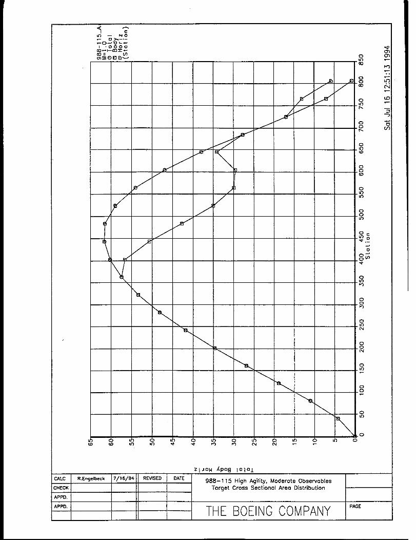
-- NO_O_ _
I.OOOO
t
f
i\
/
Jf
\
_O ¢0 ID U3 ,d"
=I
]
•d" PO PO (%1 04
OtO00
O,_ _ o
L,3p,,
OOp,,
0
0
_D
0
C)_0
0
°_
o_.0
0_tr_rO
0
0.LO
0_0
0.tO
0.0
_0
.0
0
0"_
r_3
CO
CM :KlAPPD.
APPD.
R.Engelbeck
7/16/94. I
REVISED
DATE
Z ! JOH J(po8 I o_,°l
988-1 i5 High Agility, Moderote Observobles
Torget Cross Sectionol Areo Distribution
THE BOEINOCOMPANY PAGE
<
<
0h-I.:.;<
O9<
"oI
•-0 0 0 0 u3 0 0 0 0
cO 0 (2 r_O(J rnO _JO O0 r_OCJO-- 00-- (JO-- _JO c,_(JrnII 0 II ¢..) I! - 0 II - 0 |I C=} li 0 II _.) |! 0 II . f..) cO
6
_4
6
t'Nt_
0
0t'M
6
6
5
f',,I
6
6
0.0
6 6 6 c; 6 6 o 6 6 6 6 6 6
03
ilZ
ng., ,I'81 411 ,SEOOATEICHECK I
APPD. I
APPD.
"]3
988-115 High Agility, Moderate Observables
Target Cross Sectional Area Distribution
THE BOEINGCOMPANY ,,CE123
07/16/94 12:20 PM//gandalf/user/deb9848/agility_dir/aa_dir/988-115_mission
Design Mission Segment Performance Breakdown
Initial Final Fuel Time Range Mach Altitude CL CD
Weight Weight Burned (min.) (n.mi.) (feet)
Warm-up and taxi58845. 58150. 695.1 20.00 0.0 0.000 0 0.257 0.0168
Warm-up and taxi58150. 53698. 4452.3 2.00 0.0 0.300 0 0.257 0.0168
Acceleration from Mach 0.300 to Mach 0.900
53698 53023. 675.0 0.27 1.8 0.900 0 0.047 0.0114
Climb from 0.0 ft. to 44262.7 ft. at 100.8 ft/sec
53023 51821 1201.4 3.49 27.9 0.844 44263 0.257 0.0189
Cruise at Mach 0.845
51821 49543 2278.4 39.72 320.3 0.845
Loiter at 40000. ft and max L/D of 13.89
49543 44605 4937.6 90.00 687.7 0.800
Acceleration from Mach 0.800 to Mach 1.500
44605 43788 817.2 0.88 9.6 1.500
Cruise at Mach 1.500
43788 41638 2149.6 6.31 90.4 1.500
One Combat Turn at 8.2 deg/sec and 4.0 g's
42318 41105 533.3 0.73 6.3 0.900
One Combat Turn at 8.3 deg/sec and 4.1 g's
41785 40579 526.0 0.72 6.2 0.900
One Combat Turn at 8.5 deg/sec and 4.1 g's
41009 40060 518.9 0.71 6.1 0.900
One Combat Turn at 8.6 deg/sec and 4.2 g's
40131 39548 511.8 0.70 6.0 0.900 40000 0.739 0.1000
Climb from 40000.0 ft. to 49739.0 ft. at 78.4 ft/sec
39548 39310 238.1 1.64 12.9 0.829 49739 0.310 0.0222
Cruise at Mach 0.820
39310 36869 2441.2 55.51 437.1 0.820 49815. 0.325 0.0230
Loiter at 0. ft and max L/D of 15.34
36869. 35858 1011.5 20.00 67.8 0.307 0. 0.257 0.0168
Total Mission Fuel = 22987. ibs Reserve Fuel = 1149. ibs
44994 0.323 0.0226
40000 0.263 0.0190
40000 0.073 0.0284
40000 0.068 0.0276
40000 0.739 0.1000
40000 0.739 0.I000
40000 0.739 0.I000
Power Net Fuel Error
Setting Thrust Flow Code
0.040 1713. 2085.
2.000 70292. 133570.
2.000 83174. 172232.
2.000 11680. 11348.
0.387 3538. 3407.
0.305 3387. 3248.
2.000 36153. 70381.
0.961 17345. 20426.
2.000 22658. 43870.
2.000 22658
2.000 22658
2.000 22658
2.000 7554
0.378 2695
0.055 2370
43870.
43870.
43870.
7394.
2592.
3020.
//gandalf/user/deb9848/agility_dir/aa_dir/988-115_perf 07/16/94 12:24 PM
26 WEIGHT
xNegPs 48510.23CCEL 47698.18
axRC 48510.23
WFuel 55267.35
LOAD2 48510.23
LOAD3 48510.23
LOAD4 48510.23
LOAD1 48510.23
LOAD2 48510.23
LOAD3 48510.23
LOAD4 48510.23
LOAD5 48510.23
LOAD6 48510.23
LOAD7 48510.23
S1 48510.23
$2 48510.23
$3 48510.23
$4 48510.23
54 55267.35
$6 48510.23
$7 48510.23
$8 48510.23
$9 48510.23
SI0 48510.23
SII 48510.23
S12 48510.23
%Fuel Payload
0 60 1120.00
0 60 1120.00
0 60 1120.00
0 00 1120.00
0 60 1120.00
0 60 1120.00
0 60 1120.00
0 60 1120.00
0 60 1120.00
0.60 1120.00
0.60 1120.00
0.60 1120.00
0.60 1120.00
0.60 1120.00
0.60 1120.00
0.60 1120.00
0.60 1120.00
0.60 1120.00
0.60 1120.00
0.60 1120.00
0.60 1120.00
0.60 1120.00
0.60 1120.00
0.60 1120.00
0.60 1120.00
0.60 1120.00
DeltaF
0.00
0.00
0.00
0 O0
0 O0
0 O0
0 O0
0 O0
0 O0
0 O0
0 O0
0 O0
0 O0
0 O0
0 O0
0 O0
0 O0
0 O0
0 O0
0.00
0.00
0.00
0.00
0.00
0.00
0.00
< ...... Inital ..... >< ....... Final ....... >
Pset
2.00
2.00
2.00
2.00
2.00
2.00
2.00
2.00
2.00
2.00
2.00
2.00
2.00
2.00
2.00
2.00
2.00
2.00
2.00
2 O0
2 O0
2 O02 O0
2 O02 O0
2 O0
Mach Altitude
0.60 15000.00
0.90 40000.00
0.60 50000.00
0.60 50000.00
0.90 20000.00
0.90 30000.00
1.20 30000.00
0.60 10000.00
0 90 i0000.00
0 60 20000.00
0 90 20000.00
1 20 20000.00
0 90 3OOO0.O0
1 20 30000.00
0 6O 0.00
0 90 0.00
0 60 i0000.00
0 90 10000.00
1 20 10000.00
0 60 20000.00
0 90 20000.00
1 20 20000.00
1 40 20000.00
0 90 3OO0O.00
1 20 30000.00
1 40 30000.00
Mach
0 00
1 50 40000.00
0 00 0.00
0 00 0.00
0 00 0.00
0 00 0.00
0 00 0.00
0.00 0.00
0.00 0.00
0.00 0.00
0.00 0.00
0.00 0.00
0.00 0.00
0.00 0.00
0.00 0.00
0.00 0.00
0.00 0.00
0.00 0.00
0.00 0.00
0.00 0.00
0.00 0.00
0.00 0.00
0.00 0.00
0.00 0.00
0.00 0.00
0.00 0.00
Altitude Require Actual0.00 -i00.00 -53.41
60.00 51.60
500.00 6639.37
500.00 21080.20
9.00 9.00
9.00 9.00
9.00 9.00
6.00 6.40
9.00 9.00
4.40 4.40
7.00 8.32
6.80 7.90
5.00 5.49
5.00 5.83
900.00 968.22
1300.00 1442.85
650.00 716.27
1000.00 1143.51
600.00 998.04
450.00 484.50
800.00 840.16
650.00 781.47
600.00 811.69
550.00 554.71
500.00 628.82
600.00 752.68
..A
_OOn
Model 988-114, Medium Agility - Low Observables
The medium agility, low observables vehicle, Model 988-114, is a single place tail-less supersonicdesign powered by two afterbuming low-bypass turbofans of 36200 pounds (augmented) thrusteach. It is capable of Mach 1.5 on un-augmented engine thrust. Low observable characteristicsinclude low sideslope angles, long planform outline edges, edge alignment, lack of any vertical tailsurfaces, and inlets integrated into the wing-body junction.
The wing planform was chosen to allow some forward sweep on the trailing edge while maintaining thedesired (reference) aspect ratio of 4. The tip was "beveled" to alleviate undesirable aerodynamic,structural and RCS effects.
Inlets are canted F-22 type, with angles chosen to integrate with the leading edge while meeting sideslope and inlet ramp angle requirements. Placement at the wing-body junction results in the intakeduct passing alongside rather than over the weapons bay. Yaw vectoring exhaust nozzles are locatedon the upper aft fuselage; their fairing widths determine the thrust centerline spacing.
Control effectors include those on the trailing edge of the wing, the yaw vectoring nozzles, "yawvanes" forming the forward part of the nozzle fairings (and on the underside of the aft fuselage), andaft body flaps to provide thrust vectoring in pitch. There are large leading edge slats to enhancemaneuvering. The mid-outboard elevons are splitto act as drag rudders.
The interior layout, as shown by the Inboard Profile (ASC988-114-2) is conventional for tactical aircraft,with the exception of the internal weapons bay (side-by-side missiles) and exhaust nozzlearrangement. Most the fuel is contained in the large integral wing tanks, with a smaller, protected tankabove the weapons bay for balance.
The exhaust system includes full augmentation, and a rotating nozzle with variable throat and exitplane areas; an alternate aft body integration scheme is shown (versus 988-115 or -118). In the cruiseposition, the aft body flaps provide a "SERN" expansion surface; at any substantial vector angle, thenozzle must act as a 2D-CD nozzle. Achieving acceptable efficiencies and effective vectoring is asignificant technical risk (see Section 7.0).
126
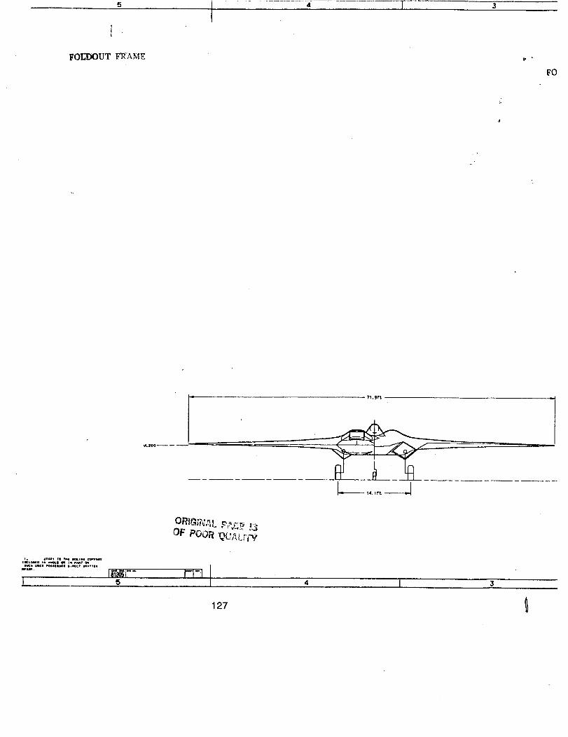
4 T
FO
OF POOR
...... :',T._,I°_._..','*.=''_
L, s 4 I
127

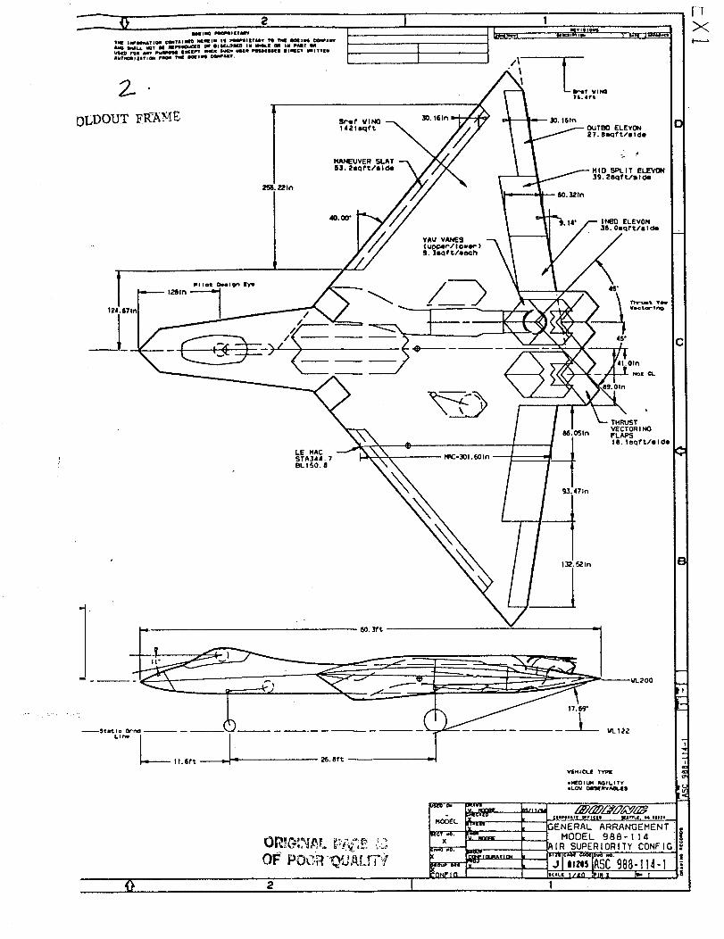
2
ME;=301.6Oln
MID SPLIT E_
39, 28qf ?./s I Oe
INSDELEVON
MOOEL x
l_¢I too. [.alX Vm_RE L-------
?_ENERAL ARRANGEMENT
MODEL 9B8-114
_,[R SUPERIORITY CONFIG
i¢ic¢ S/de IPlfl l[ _'_ I
1

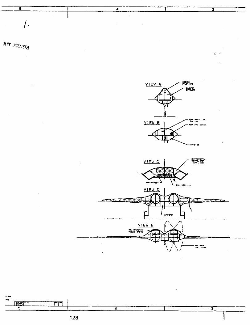
•
VIE_ A
VIEW D
_n_urT
tit
4 I 3
128

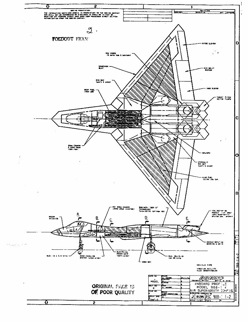
_ I0 2 I
ilal i i_t I_IOlI iII t lilt i
lINE II_(I_TII_I @DIITAIIMI@ NIIIIIIII III II_IIILTIi'V 1FI Till Illlqllll @ll_ll_
l_lll4OmlllYlt)ll I II II1111 C_sPI. I
o
.%.___.__.E."__ --.j __-.-...._.......
o 2 I
D
C
B:

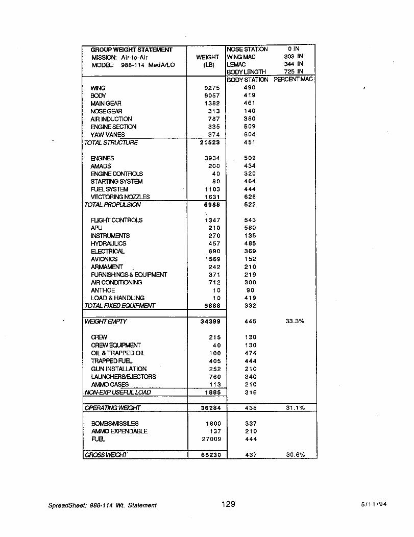
GROUP WBGHT STATEMENT
MISSION: Air-to-Air
MODEL: 988-114 MedA/LO
W_G
BODY
MAIN GEAR
NOSEGEAR
AIR INDUCTION
ENG_qE SECTK_N
YAW VANES
WEIGHT
(LB)
9275
9057
1382
313
787
335
374
TOTAL STRUCTURE
ENGNES
AMADS
ENGINE CONTROLS
STARTING SYSTEM
FUEL SYSTI_I
VECTORING NOZZLES
TOTAL PROPULSION
FUGHT CONTROLS
APU
INSTRUMENTS
HYDRAULICS
ELECTRICAL
AVIONICS
ARMAMENT
FURNISHINGS & EQUIPMENT
AIR CONDITIONING
ANTI-ICE
LOAD & HANDLING
TOTAL FIXED EQUIPMENT
_EMPTY
ClEW
CREW EQUIPMENT
OIL & TRAPPED OIL
TRAPPED FUEL
GUN INSTALLATION
LAUNCHERS/EJECTORS
AMIVlO CASES
NC_EXP USEFUL LOAD
21523
3934
2OO
4O
8O
1103
1.631
6988
1347
210
270
457
69O
1569
242
371
712
10
10
5888
34399
215
40
100
405
252
760
113
1885
OPERARNGWE/GHT 36284
BOMBS_IlSSlLES
AMMO EXPENDABLE
FUEL
GROSSV_GNT
1800
137
27009
65230
NOSE STATION
WING MAC
JEMAC
BODY I_B'qGTH
0 IN
303 IN
344 IN
725 IN
BODY STATION
49O
419
461
140
360
5O9
604
451
PERCENT MAC
509
434
320
464
444
626
522
543
580
135
485
369
152
210
219
300
90
419
332
445 33.3%
130
130
474
444
210
340
210
316
438 31.1%
337
210
444
437 3O.6%
SpreadSheet: 988-114 Wt. Statement 129 5/11/94
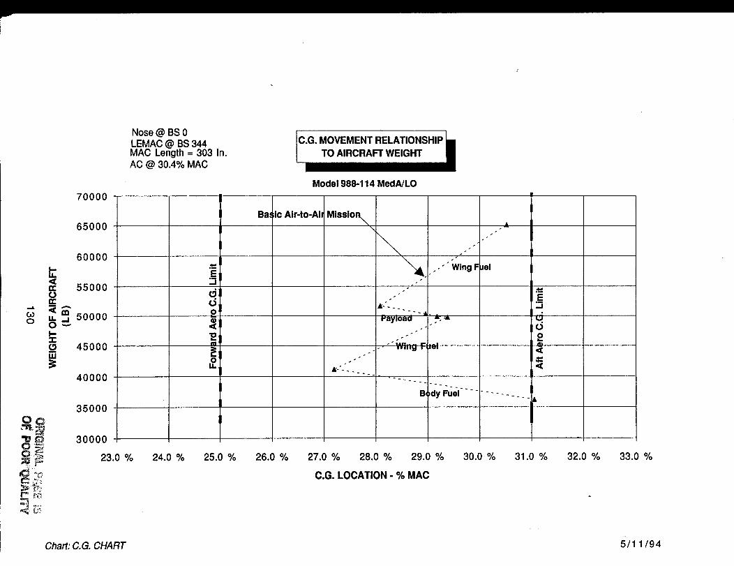
8
W
70000
65000
60000
55000
50000
45000
40000
35000
30000
23.0 %
Nose @ BS 0LEMAC @ BS 344MAC Length = 303 In.AC @ 30.4% MAC
Model 988-114 MedA/LO
dJ
d).o
i
Ba=ic Air-to-Aim
\
"iPayload
.-'" W;i-,§ F
"" _Ning F
,dy Fuel
•A
Jal
°m
.E
O
2<
<
24.0 % 25.0 % 26.0 % 27.0 % 28.0 % 29.0 %
C.G. LOCATION - % MAC
30.0 % 31.0 % 32.0 % 33.0 %
Chart: C.G. CHART 5/1 1/94
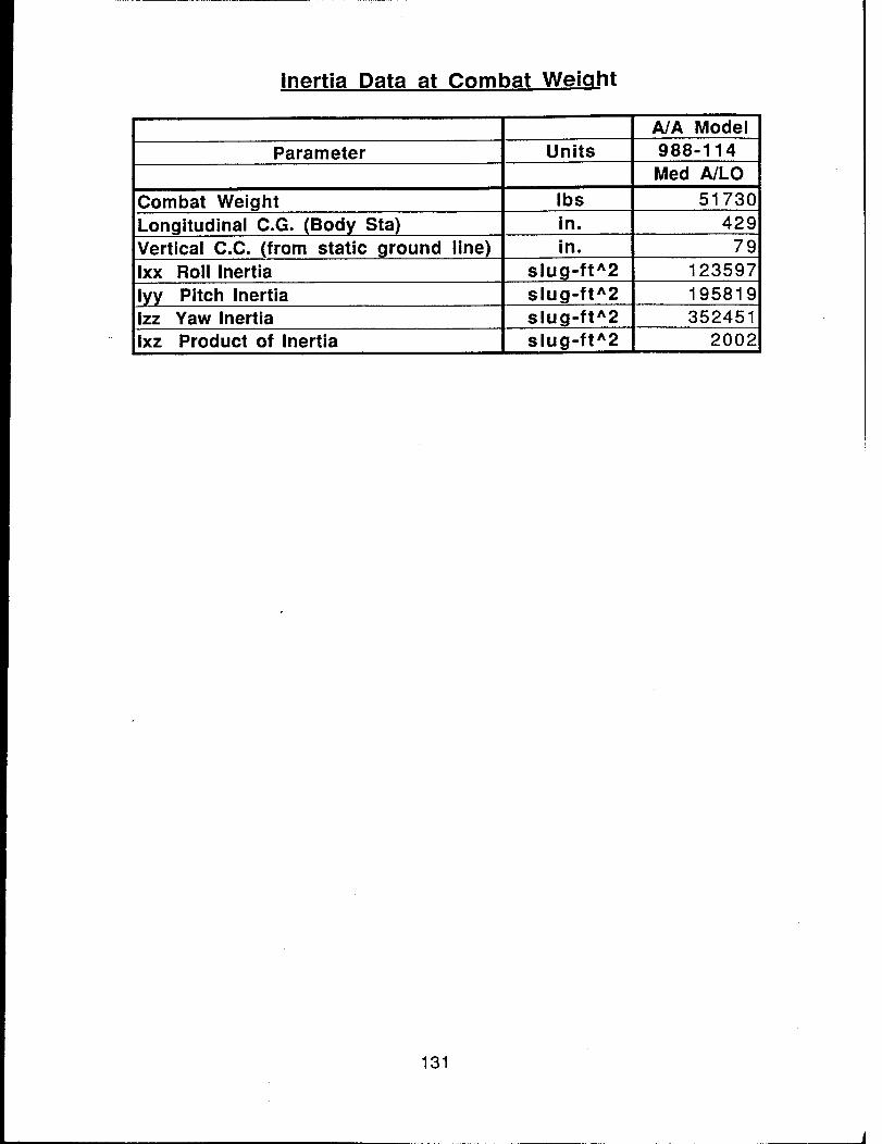
Inertia Data at Combat Weiaht
A/A Model
Parameter Units 988-114
Med A/LO
Combat Weight Ibs 51 730in. 429Longitudinal C.G. (Body Sta)
Vertical C.C. (from static ground line) in° 79
Ixx Roll Inertia slug-ft^2 123597
iyy Pitch Inertia slug-ft^2 195819
izz Yaw Inertia slug-ft^2 352451
Ixz Product of Inertia slug-ft^2 2002
131
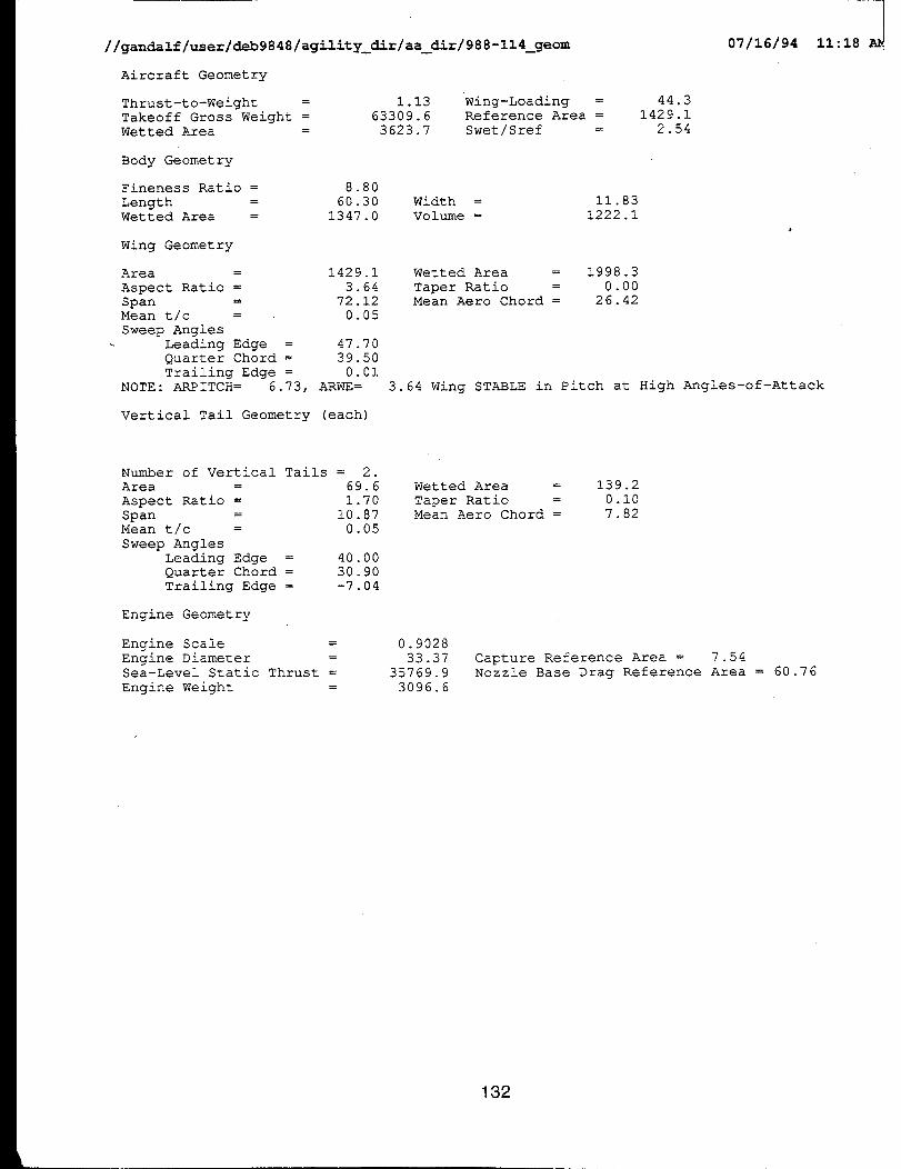
//gandalf/user/deb9848/agility_dir/aa_dir/988-114_geom
Aircraft Geometry
Thrust-to-Weight =
Takeoff Gross Weight =
Wetted Area =
1.13 Wing-Loading =
63309.6 Reference Area =
3623.7 Swet/Sref =
44.3
1429 .i
2.54
07/16/94
Body Geometry
Fineness Ratio = 8.80
Length = 60.30 Width =
Wetted Area = 1347.0 Volume =
Wing Geometry
11.83
1222.1
Area = 1429.1
Aspect Ratio = 3.64
Span = 72.12
Mean t/c = 0.05
Sweep Angles
Leading Edge = 47.70
Quarter Chord = 39.50
Trailing Edge = 0.01
NOTE: ARPITCH = 6.73, ARWE=
Wetted Area = 1998.3
Taper Ratio = 0.00
Mean Aero Chord = 26.42
3.64 Wing STABLE in Pitch at High Angles-of-Attack
Vertical Tail Geometry (each)
Number of Vertical Tails = 2.
Area = 69.6
Aspect Ratio = 1.70
Span = 10.87
Mean t/c = 0.05
Sweep Angles
Leading Edge = 40.00
Quarter Chord = 30.90
Trailing Edge = -7.04
Engine Geometry
Engine Scale = 0.9028
Engine Diameter = 33.37
Sea-Level Static Thrust = 35769.9
Engine Weight = 3096.6
wetted Area = 139.2
Taper Ratio = 0.I0
Mean Aero Chord = 7.82
Capture Reference Area = 7.54
Nozzle Base Drag Reference Area = 60.76
132
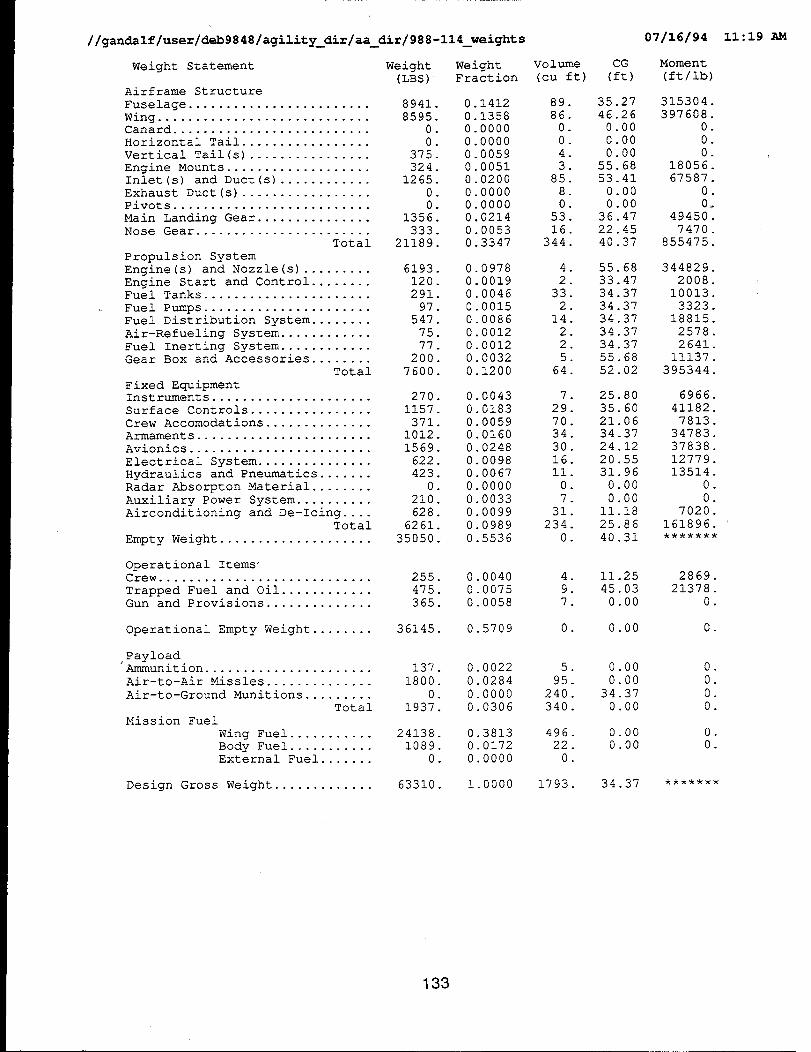
//gandalf/user/deb9848/agility_dir/aa_dir/988-114_weights 07/16/94 II :19 AM
Weight Statement Weight Weight Volume(LBS) Fraction (cu ft)
Airframe Structure
Fuselage ........................ 8941•Wing ............................ 8595.Canard .......................... 0.
Horizontal Tail ................. 0.
Vertical Tail(s) ................ 375.
Engine Mounts ................... 324.Inlet (s) and Duct (s) ............ 1265.Exhaust Duct (s) ................. 0.Pivots .......................... 0.
Main Landing Gear ............... 1356.Nose Gear ....................... 333
Total 21189
Propulsion System
Engine(s) and Nozzle(s) ......... 6193Engine Start and Control ........ 120Fuel Tanks ...................... 291
Fuel Pumps ...................... 97
Fuel Distribution System ........ 547
Air-Refueling System ............ 75Fuel Inerting System ............ 77Gear Box and Accessories ........ 200
Total 7600
Fixed EquipmentInstruments ..................... 270Surface Controls ................ 1157
Crew Accomodations .............. 371Armaments ....................... 1012
Avionics ........................ 1569
Electrical System ............... 622Hydraulics and Pneumatics ....... 423
Radar Absorpton Material ........ 0
Auxiliary Power System .......... 210
Airconditioning and De-Icing .... 628Total 6261
Empty Weight .................... 35050
0.14120.1358
0.00000 0000
0 00590 0051
0 02000 0000
0 00000.0214
. 0•0053
• 0•3347
0.09780.0019
0.0046
0.00150.0086
0.0012
0.00120.0032
0•1200
0 0043
0 01830 0059
0 01600 0248
0 0098
0 00670 0000
0 0033
0 0099
0 0989
0 5536
Operational Items"Crew ............................ 255.
Trapped Fuel and Oil ............ 475.Gun and Provisions .............. 365.
0.00400•0075
0.0058
Operational Empty Weight ........ 36145• 0•5709
Payload"Ammunition ...................... 137.
Air-to-Air Missles .............. 1800.
Air-to-Ground Munitions ......... 0.
Total 1937.
Mission Fuel
Wing Fuel ........... 24138.Body Fuel ........... 1089.External Fuel ....... 0.
0.0022
0.0284
0.00000.0306
0.3813
0.01720.0000
Design Gross Weight ............. 63310• 1.0000
89.
86.0.0.
4.
385
80
53
16344
4
233
2
142
2
5
64
7 •
29.
70.34.
30.
16.ii.
0.
7.
31.234.
0.
4.
9.
7.
0 .
5 .
95.240.
340.
496.22.
0.
1793•
CG
(ft)
35.27
46.26
0.000.00
0.0055.68
53.41
0.000.00
36.4722.45
40.37
55.68
33.4734 37
34 37
34 3734 37
34 3755 68
52 02
25•80
35.6021.06
34.37
24.1220.55
31.96
0.00
0.0011.18
25.86
40.31
11•25
45.03
0.00
0.00
0.00
0.00
34.37
0.00
0.000.00
34.37
Moment
(ft/ib)
315304.
397608•0.
0.
0.18056.
67587.0.
0_
49450.7470.
855475•
344829
200810013
3323
188152578
264111137
395344
6966
411827813
3478337838
12779
135140
0
7020
161896
2869.21378•
0.
0 •
0 .
O.O.O.
0 .
O.
133
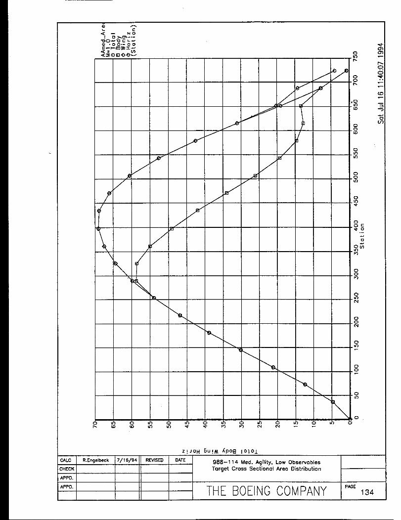
I CALC
CHECK J
APPD. I
APPD. I
NO
o-00.-0o
J#
/
/i
\ ,/_
\
_- tO tO u3
REVISED
/
S
d/
J
//
o01.tO
P-
.°
OOp,.
,o
00_0
0U_u_
0
o
0
0
o 5°-
o
.o_
0_0_3
0
D_
0_0C_
0
0.0
THE BOEINGCOMPANY P,0E134
988-114 Med. Agility, Low Observables
Target Cross Sectional Area Distribution
Z ! JO H 6U !M /[poll 101ol
\ .o
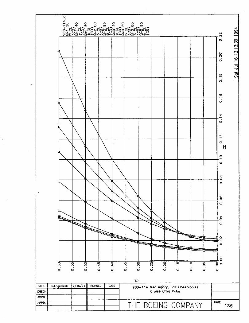
"OI
,,¢_C) 0 0 0 _ {D C) 0 0
CO II 0 I! C.) II C.) II . 0 II CJ II 0 II _.) II 0 II C..)
C%1
0
_b
0
CO
6
r_
0
0
4.-
0
(3o
0
.0
0
_0
6
.0
O
,O
OO
O
0164
CO
"5-D
CAhC R.Engelbeck
lO
988-114 Med Agility, Low ObservoblesCruise Drog Polor
THE BOEINGCOMPANY "'°_ls5
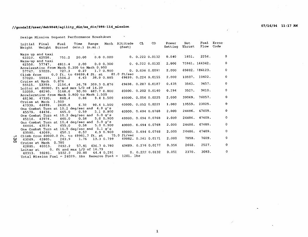
//gandalf/user/deb9848/agility_dir/aa_dir/988-114_mission
Design Mission Segment Performance Breakdown
Initial Final Fuel Time Range
Weight Weight Burned (min.) (n.mi.)
Warm-up and taxi
63310. 62558. 751.2 20.00 0.0 0 000
Warm-up and taxi62558. 57747. 4811.4 2.00 0.0 0 300
Acceleration from Mach 0.300 to Mach 0.900
57747. 57020. 727.3 0.27 1.7 0 900
Climb from 0.0 ft. to 49699.4 ft. at 81.0 ft/sec
57020. 55515 1504.2 4.63 38.9 0 885 49699
Cruise at Mach 0.876
55515. 53359 2156.4 36.78 309.3 0 876 49698
Loiter at 40000. ft and max L/D of 14.39
53359. 48190 5168.6 90.00 687.7 0 800 40000
Acceleration from Mach 0.800 to Mach 1.500
48190 47330 860.4 0.86 9.4 1 500 40000
Cruise at Mach 1.500
47330 44899 2430.8 6.32 90.6 1 500 40000
One Combat Turn at 10.2 deg/sec and 4.9 g's
45579 44434 465.0 0.59 5.1 0.900 40000
One Combat Turn at 10.3 deg/sec and 5.0 g's
45114 43974 460.0 0.58 5.0 0.900 40000
One Combat Turn at 10.4 deg/sec and 5.0 g's
44404 43519 455.0 0.58 5.0 0.900 40000
One Combat Turn at 10.5 deg/sec and 5.1 g's
43590. 43069 450.1 0.57 4.9 0.900 40000
-_ Climb from 40000.0 ft. to 49981.7 ft. at 75.0 ft/sec
CO 43069. 42805 263.9 1.76 13.3 0.799 49982
O_ Cruise at Mach 0.780
42805. 40313. 2492.2 57.91 436.7 0.780 49689. 0.276 0.0177
Loiter at 0. ft and max L/D of 16.79
40313. 39281. 1032.2 20.00 64.4 0.291 0. 0.222 0.0132
Total Mission Fuel = 24029. ibs Reserve Fuel = 1201. ibs
Mach Altitude CL CD
(feet)
0. 0.222 0.0132
0. 0.222 0.0132
0. 0.036 0.0091
0.224 0.0155
0.287 0.0187
0.202 0.0140
0.056 0.0225
0.052 0.0221
0.694 0.0768
0.694 0.0768
0.694 0.0768
0.694 0.0768
0.261 0.0171
Power Net
Setting Thrust
0.040 1851. 2254.
2.000 75961. 144342.
2.000 89882. 186123.
2.000 10507. 10422.
0.435 3543. 3457.
0.294 3527. 3410.
2.000 39069 76057.
1.003 19559 23025.
2.000 24486 47409.
2.000 24486 47409.
2.000 24486 47409.
2.000 24486 47409.
2.000 7858 7609.
0.356 2668. 2527.
0.051 2370. 3083.
Fuel Error
Flow Code
0
0
0
0
0
0
0
0
0
0
0
0
0
0
0
07/16/94 11:17 AM
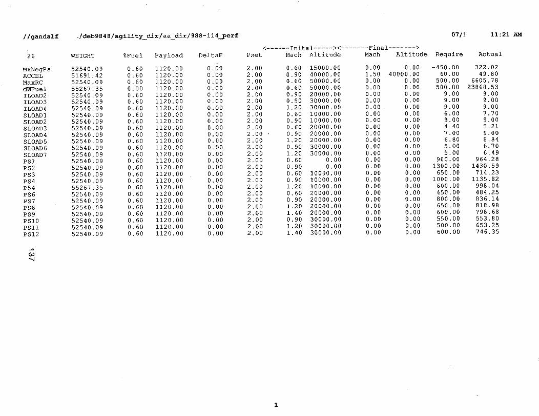
//gandalf ./deb9848/agility_dir/aa_dir/988-114_perf 07/I 11:21 AM
26
MxNegPsACCEL
MaxRC
dWFuelILOAD2
ILOAD3ILOAD4
SLOADISLOAD2
SLOAD3
SLOAD4
SLOAD5SLOAD6
SLOAD7
PSIPS2
PS3
PS4
P54PS6
PS7
PS8PS9
PSI0
PSI1
PSI2
..K
Co-4
WEIGHT %Fuel Payload
52540.09
51691.4252540.09
55267.35
52540.0952540.09
52540.09
52540.0952540.09
52540.09
52540.0952540.09
52540.09
52540.0952540.09
52540.09
52540.0952540.09
55267.35
52540.09
52540.0952540.09
52540.09
52540.0952540.09
52540.09
0.600.60
0.60
0.00
0.600.600 60
0 60
0 60
0 600 60
0 600 60
0 6O
0 600.600 600 600 600 600 600 6O0 6O0 600 600 60
1120.00
1120.00
1120.001120.00
1120 001120 00
1120 00
1120 001120 00
1120 00
1120 001120 00
1120 00
1120 00
1120 001120 00
1120 00
1120 001120 00
1120 00
1120 001120 00
1120 00
1120 001120.00
1120.00
DeltaF
0.60
0.000.00
0.00
0.000.00
0.00
0 000 00
0 00
0 000 00
0 00
0 000 00
0 00
0 000 00
0 00
0 00
0 000 O0
0 000 00
0.00
0.00
< ...... Inital ..... ><
Pset Mach Altitude
2.00
2.002.00
2.00
2.002.00
2.002.00
2 00
2 002 00
2 00
2 002 00
2 00
2 002 00
2 00
2 00
2 002 00
2 002 00
2 00
2 00
2 00
0.60
0.90
0.600.60
0.90
0.90I .20
0.600.90
0.60
0.90
1.200 90
1 20
0 600 9O
0 60
0 901 20
0 6O
0 9O1 20
1 40
0 90
1 201 40
15000.00
40000.00
50000.0050000.00
20000.003O0OO.0O
30000.00
10000.00I0000.00
20000.00
20000 0020000 00
3O0OO 00
30000 000 00
0 00
I0000 0010000 00
I0000 00
20000 0020000 00
2O0O0 00
20000 0030000 00
30000 00
3O0OO 00
Final >Mach Altitude
0 00 0 00
1 50 4OOOO 000 00 0 00
0 00 0 00
0 00 0 000 00 0 00
0.00 0.000.00 0.00
0.00 0.00
0.00 0.000.00 0.00
0.00 0.000.00 0.00
0.00 0.00
0.00 0.00
0.00 0.00
0.00 0.000.00 0.00
0.00 0.00
0.00 0.000.00 0.00
0.00 0.000.00 0.00
0.00 0.00
0.00 0.00
0.00 0.00
Require
-450.00
60.00
500.00
5O0.OO9.009.00
9.00
6.00
9.004.40
7.OO6.80
5.00
5.00900.00
1300.00
650.00I000.00
600.00
450.00800.00
65O.O0
600.00550.00
50O.00
600.00
Actual
322.02
49.80
6605 78
23868 539 009 00
9 00
7 70
9.005.21
9.008.84
6.70
6.49964.28
1430.59
714.231135.82
998.04
484.25836.14
818.98798.68
553.80
653.25
746.35
1

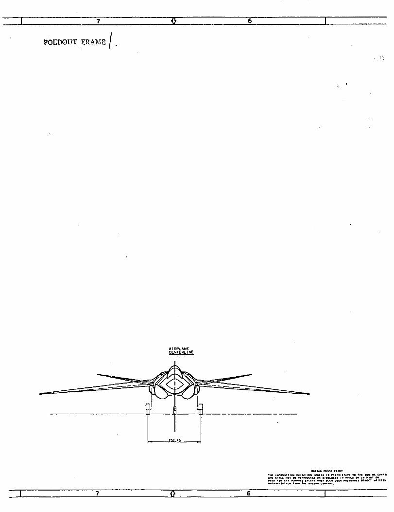
7 9 6 j
FOUDOU_ ERA_ [.
A |fq!l:%A_
CF.NT£RL. l NE
_o ?1_ _v p_,lmOSl TI_EpT uNIi DLXC_ _ _J_E_la| DIm_¢T WIITTEI
_'1 7 0 6 I

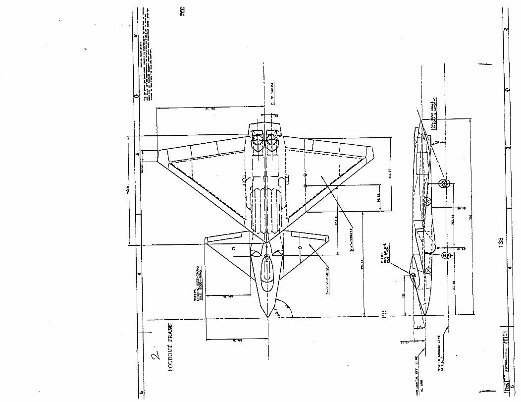
_
I I i
,!i,
/Li! i!t/!!ll/ / iil_
' II
I
I
o
0
©
I
a

6.3 Multi-Role Concepts
Model 988-119, High Agility, Moderate Observables
The high agility, moderate observables vehicle, Model 988-119, is a single place tail-less transdnicdesign powered by two afterburning low-bypass turbofans of 28500 pounds (augmented) thrusteach. It is capable over Mach 1.5 on augmented engine thrust. Reduced signature characteristicsinclude moderate sideslope angles, edge alignment, lack of any vertical tail surfaces, and inletsintegrated into the wing-body junction.
The modified trapezoid planform was chosen to allow a higher aspect ratio without excessively narrowtip chords. Placement of the wing on the body for proper balance required the use of a canard insteadof a conventional horizontal tail.
Inlets are F-22 type, with angles chosen to align with the trailing edge while meeting side slope andinlet ramp angle requirements. Placement at the wing-body junctionresults in the intake duct passingalongside rather than over the weapons bay. Yaw vectoring exhaust nozzles are located in the aftfuselage.
Control effectors include those on the trailing edge of the wing, the canards, the yaw vectoringnozzles, "yaw vanes" forming the forward part of the nozzle fairings, and aft body flaps to providethrust vectoring in pitch. There are large leading edge slats to enhance maneuvering. The mid-outboard elevons are split to act as drag rudders.
The canards require high deflection capability to allow for effectiveness in high-Alpha maneuvers.They have 10 degrees of dihedral to reduce interference with the wing and inlets.
The interior layout, as shown by the Inboard Profile (ASC988-119-2) is conventionalfor tactical aircraft,with the exception of the internal weapons bay (side-by-side bombs/missiles) and exhaust nozzlearrangement. The fuel is contained in integral wing tanks, and a protected tank above the weaponsbay.
The exhaust system includes full augmentation, and dual rotating nozzles with variable throat and exitplane areas; this is an alternate nozzle arrangment from the single rotating nozzles shown on the otherconfigurations. It appears to offer reduced flow-turning losses and improved aft-body integration. Italso offers better pitch vectoring effectiveness (with the vectoring flap located between the nozzles),along with more flexibility for simultaneous yaw and pitch vectoring through differential pivoting of theupper and lower nozzles. There is not as much duct offset, but this is acceptable for a moderateobservables aircraft. Achieving acceptable efficiencies and effective vectoring is a significanttechnical risk (see Section 7.0).
139

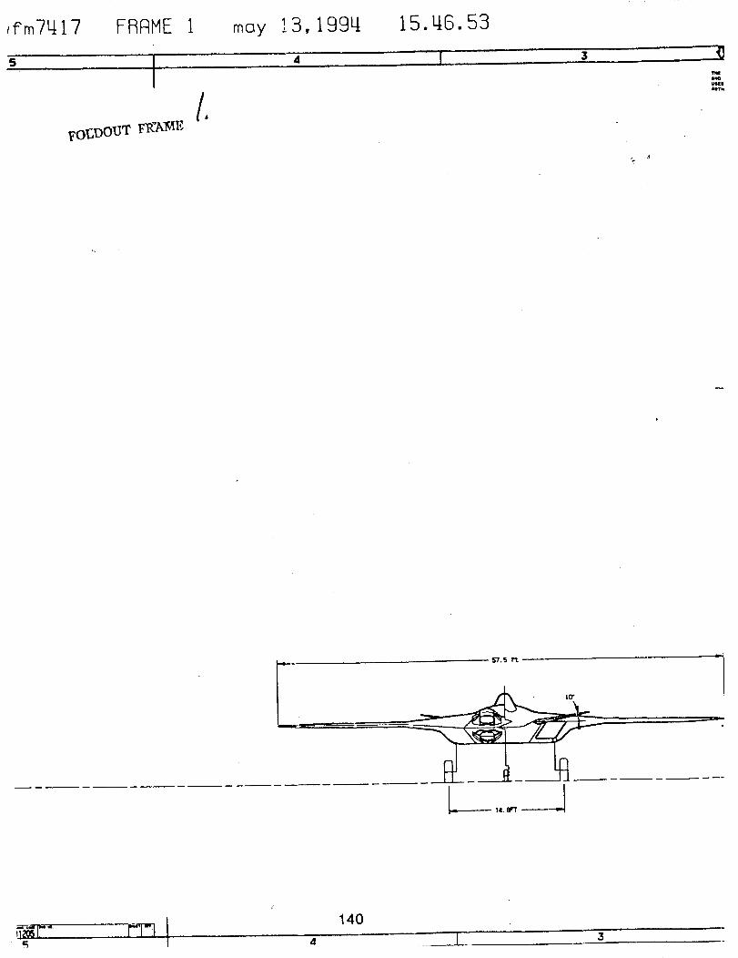
,fm7_17
?o_]DOUT FR_A]ME
moy 13,199u,
d
15.u,6.53
moAw,n.
. 57.S rt
_-._ Id. 8FT ----------4w.
140

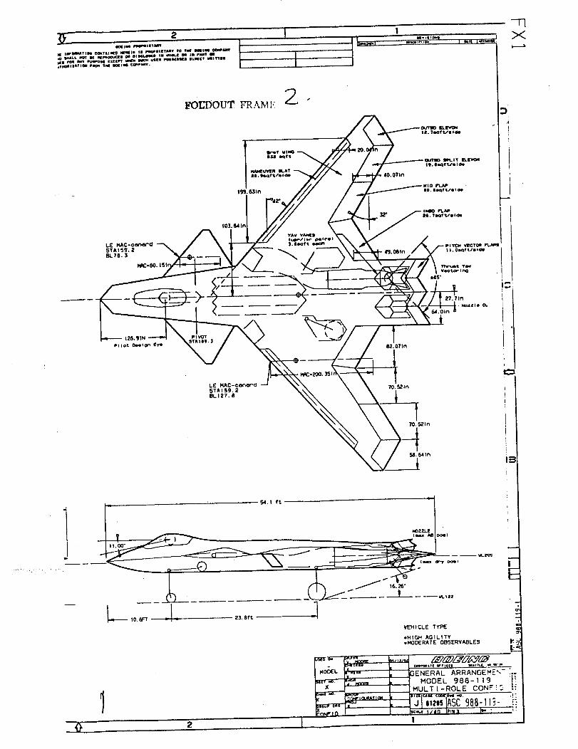
2
l_lml _'l_ll'm I[TI'rr Iizo rOLl _ _ EXcz_T _ _ _LeR POHEI_IR DIHCT EIITSlljT_I|_T;QII Prom 5_lt I_GIN ¢_*tDLLGT.
X
40.071n
1O. IHf _/11 do
F...J
PI_DT
?0. S21f_
_EH ICLE TYPE
*HIGH 'AGILITY.HODERATE O_SERVA_LES
. _,T( wrltll IIlIM. I w._,
'" 3ENERAL ARRANGEHE'_", _,_ MODEL 986-119
MULTI -ROLE CONF !
1 ,=
I
.1"[
2

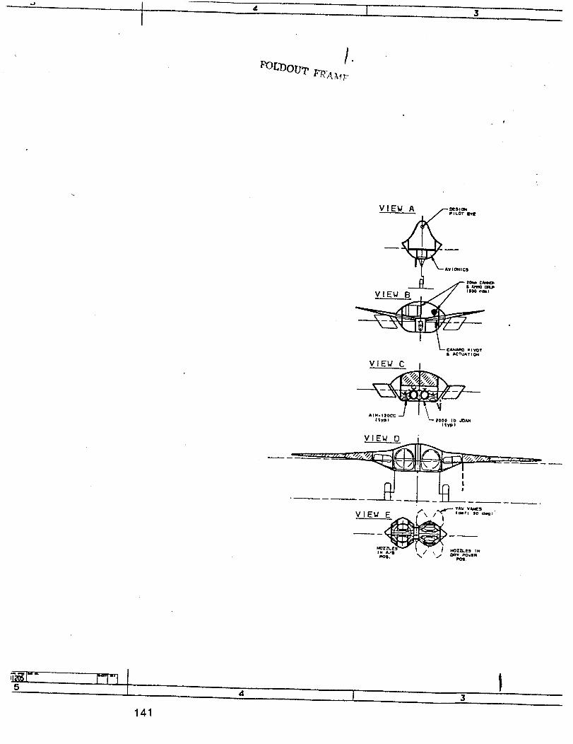
I 3
• _TUATION
AIM- I _tO__'7;_ -' " L,ooo,,,t tyl_)
141
4

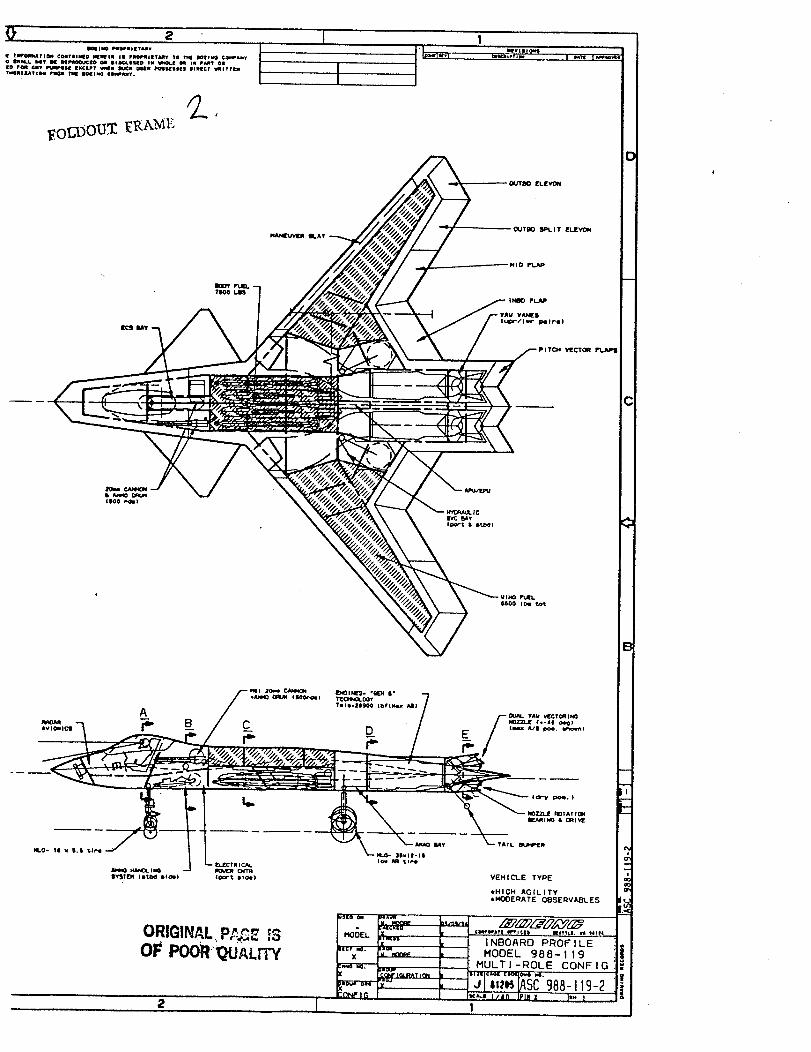
- -- _-__: ___=A___-]-_- _ ---
IY'_i'Oi llllUl4 lll_ll (¢_'% lllaill VEHIC"LE TYPE
IHIGH AG|/ITY
*HOO£1_ATE O_SE _VA_I.ES
s[o i IIIW
ORIGIiklAL.P_&I_,. iS l .o_ ,',-,, |lllt_elliill It"ll¢|ll _littlll, ill 11111*
INBOARD PROFILE
MODEL 988-I19
MULTI-ROLE CONFIO
Icli.l I/in Jill ! I_. i

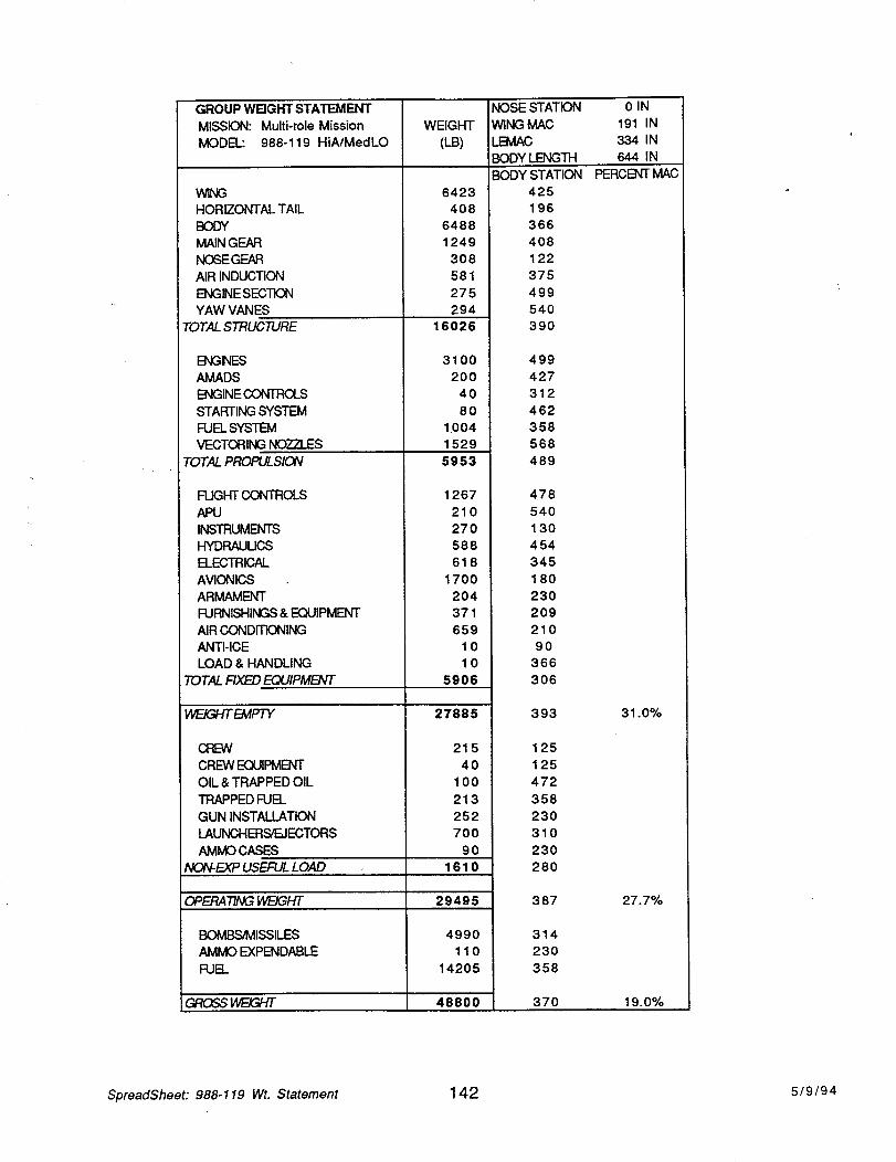
GROUP WEIGHT STA1--P...MENT
MISSION: Multi-role Mission
MODEL: 988-119 HiA/MedLO
WNG
HORIZONTAL TAIL
BODY
MAIN GEAR
NOSEGEAR
AIR INDUCTION
ENGINE SECTION
YAW VANES
TOTAL STRUCTURE
ENGNES
AMADS
ENGINE CONTROLS
STARTING SYSTEM
FUEL SYSTEM
VECTORING NOZZLES
TOTAL PROPULSION
FUGHT CONTROLS
APU
INSTRUMENTS
HYDRAUUCS
ELECTRICAL
AVIONICS
ARMAMENT
FURNISHINGS & EQUIPMENT
AIR CONDITIONING
ANTI-ICE
LOAD & HANDLING
TOTAL FIXED EQUIPMENT
HnEICY-fi'EMPTY
CREW
CREW EOJIPMENT
OIL & TRAPPED OIL
TRAPPED FUEL
GUN INSTALLATION
LAUNCHER_EJECTORS
AMMO CASES
NQN-EXP USEFUL LOAD
WEIGHT
(L.B)
6423
408
6488
1249
308
581
275
294
16026
3100
200
40
80
1.004
1529
5953
1267
210
270
588
618
1700
204
371
659
10
10
5906
27885
215
40
100
213
252
700
90
1610
OPERA_NGi4F=/G/-/T 29495
4990
110
14205
48800
BOMBS/MISSILES
AMMO EXPENDABLE
FUEL
GRCSS _
NOSE STATION
WING MAC
LB_AC
BODY LENGTH
BODY STATION
425
196
366
408
122
375
499
540
390
499
427
312
462
358
568
489
478
540
130
454
345
180
230
2O9
210
90
366
306
393
125
125
472
358
230
310
230
280
387
314
230
358
370
0IN
191 IN
334 IN
644 IN
PERCENT MAC
31.0%
27.7%
19.0%
SpreadSheet: 988-119 Wt. Statement 142 5/9/94

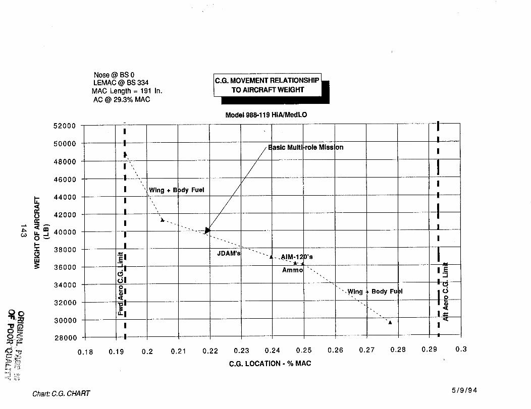
Nose @ BS 0LEMAC @ BS 334MAC Length = 191 In.AC @ 29.3% MAC
e.G. MOVEMENT RELATIONSHIP
TO AIRCRAFT WEIGHT
52000 -
50000
48000
46000
44000
42000
,oooo38000
36000
34000
32000
_,_ _oooo
=_ 28000
_
I
I
I
I
I
I
I
I
!:d!
_t!
I
W l,lg + B)dy Fuel
Model 988-119 HIA/MedLO
j//
JDAM's
/E lasic Multi
" " " " I . .AIM.12
Amino
,role Mi on
O's
"" ,Wing Body Fu
I
I
I
iI
i
,¢z
0.18 0.19 0.2 0.21 0.22 0.23 0.24 0.25 0.26 0.27 0.28 0.29 0.3
C.G. LOCATION - % MAC
Chart: C.G. CHART 5/9/94
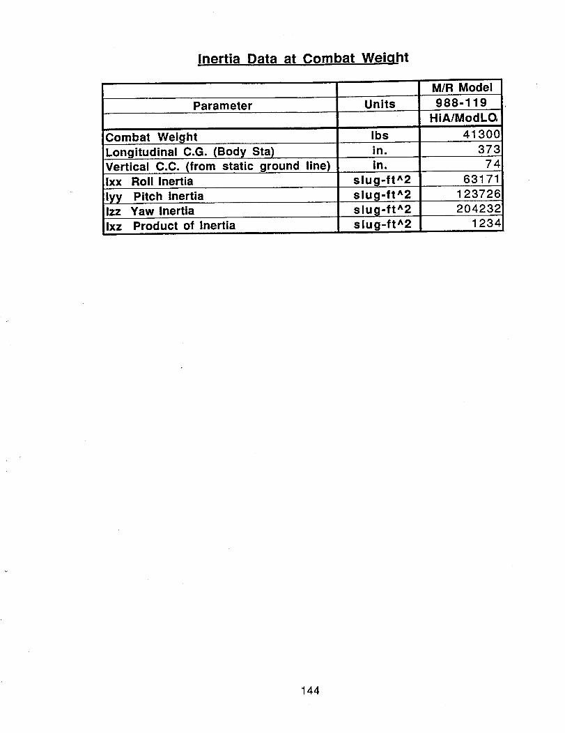
Inertia Data at Combat Weiqht
M/R Model
Parameter Units 988-119HiA/ModLO,
Combat Weight Ibs 41300in. 373Longitudinal C.G. (Body Sta)
Vertical C.C. (from static ground line
Ixx Roll Inertia
lyy Pitch InertiaIzz Yaw Inertia
Ixz Product of Inertia
in.
slug-ft^2
slug-ft^2
slug-ft^2
slug-ft^2
74
63171
123726
204232
1234
144
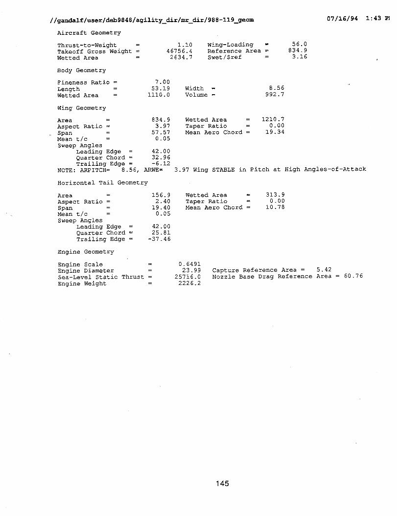
//gandalf/user/deb9848/agility_dir/mr_dir/988-119_geom 07/16/94 1:43 P]
Aircraft Geometry
Thrust-to-Weight =
Takeoff Gross weight =
Wetted Area =
I.i0 Wing-Loading =
46756.4 Reference Area =
2634.7 Swet/Sref =
56.0
834.9
3.16
Body Geometry
Fineness Ratio = 7.00
Length = 53.19 Width =
Wetted Area = iii0.0 Volume =
8.56
992.7
Wing Geometry
Area = 834.9
Aspect Ratio = 3.97
Span = 57.57
Mean t/c = 0.05
Sweep Angles
Leading Edge = 42.00
Quarter Chord = 32.96
Trailing Edge = -6.12
NOTE: ARPITCH = 8.56, ARWE=
wetted Area = 1210.7
Taper Ratio = 0.00
Mean Aero Chord = 19.34
3.97 Wing STABLE in Pitch at High Angles-of-Attack
Horizontal Tail Geometry
Area =
Aspect Ratio =
Span =
Mean t/c =
Sweep Angles
Leading Edge =
Quarter Chord =
Trailing Edge =
156.9
2.40
19.40
0.05
42.00
25.81
-37.46
Wetted Area = 313.9
Taper Ratio = 0.00
Mean Aero Chord = 10.78
Engine Geometry
Engine Scale = 0.6491
Engine Diameter = 23.99
Sea-Level Static Thrust = 25716.0
Engine Weight = 2226.2
Capture Reference Area = 5.42
Nozzle Base Drag Reference Area = 60.76
145

//gandalf/user/deb9848/agility_dir/mr_dir/988-119_weights
Weight Statement
Airframe Structure
Fuselage ........................ 6425.Wing ............................ 6262.Canard .......................... 0.
Horizontal Tail ................. 539.
Vertical Tail(s) ................ 0.
Engine Mounts ................... 159.Inlet(s) and Duct(s) ............ 421.Exhaust Duct(s) ................. 0.Pivots .......................... 0
Main Landing Gear ............... 1227Nose Gear ....................... 305
Total 15339
Propulsion System
Engine(s) and Nozzle(s) ......... 3881Engine Start and Control ........ 120Fuel Tanks ....................... 387
Fuel Pumps ...................... 21Fuel Distribution System ........ 249
Air-Refueling System ............ 63
Fuel Inerting System ............ 59Gear Box and Accessories ........ 200
Total 4980
Fixed EquipmentInstruments ..................... 270
Surface Controls ................ 1419
Crew Accomodations .............. 401Armaments ....................... 1179
Avionics ........................ 1725
Electrical System ............... 688
Hydraulics and Pneumatics ....... 423Radar Absorpton Material ........ 0
Auxiliary Power System .......... 182Airconditioning and De-lcing .... 835
Total 7122
Empty Weight .................... 27440
Weight Weight Volume(LBS) Fraction (cu ft)
0.1374
0.13390.0000
0.0115
0.00000.0034
0.0090
0.0000. 0.0000. 0.0263
. 0.0065
. 0.3281
0.0830
0.00260.0083
0.0004
0.00530.0013
0.0013
0.00430.1065
0.0058
0 0304
0 00860 0252
0 0369
0 01470 0091
0.0000
0.00390.0179
0.1523
0.5869
6463
0
50
253
13
03412
245
17
3
181
6
21
4
51
7
35
7039
3317
II.0.
6.
42.
260.
0.
Operational ItemsCrew ............................ 200. 0.0043 3.
Trapped Fuel and Oil ............ 351. 0.0075 7.Gun and Provisions .............. 342. 0.0073 7.
Operational Empty Weight ........ 28333. 0.6060 0.
PayloadAmmunition ...................... ii0. 0.0024 4.
Air-to-Air Missles .............. 690. 0.0148 65.
Air-to-Ground Munitions ......... 4300. 0.0920 97.
Total 5100. 0.1091 166.
Mission Fuel
Wing Fuel ........... 10896. 0.2330 224.Body Fuel ........... 2427. 0.0519 50.External Fuel ....... 0. 0.0000 0.
Design Gross Weight .... ......... 46756. 1.0000 1823.
CG
(ft)
28.27
30.170.00
0.00
0.0049.28
47.350.00
0.00
32.1619.88
28.94
49.28
30.18
30.3230.32
30.3230.32
30.32
49.2845.43
23.5724.34
19.5030.32
21.28
18.1929.19
0.00
0.00
10.31
21.7130.06
11.08
39.80
0.00
0.00
0.00
0.00
30.32
0.00
0.000.00
30.32
07116194
Moment
(ft/ib)
181641188946
00
0
7_4419938
0
039476
6058443904
191259
407411724
630
75491819
17877392
226234
6365
34537
782335745
3670112510
12359
00
8611.
154651.
824789.
2216.
13951.0.
0 °
0 .
O.
130369.0.
0 .
0.
824789.
1:44
146
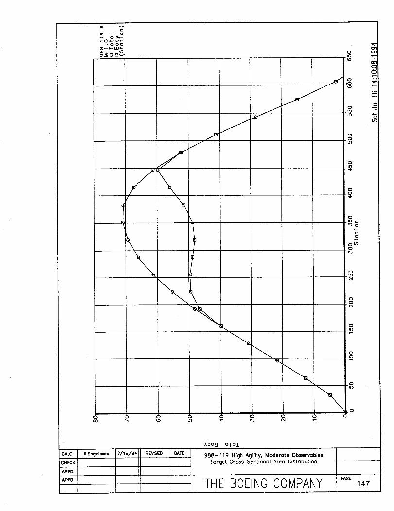
CHECK I
APPD. I
APPD. I
i.ooo
_11
/\
0D r,_ toC)
u3 ,¢
I DATE I
XpoB I o%O.L
988-119 High Agility, Moder0te Observ0blesTorget Cross Sectionol Areo Distribution
o01ub_D
q.-._
-5O "-_
O
O.tt}
.<.
O.O
'd"
O
OtnO
O
P4
O.O
P4
OL,'3
_m
O_O
.o
O
THE BOEINO COMPANY ,,,,OE147
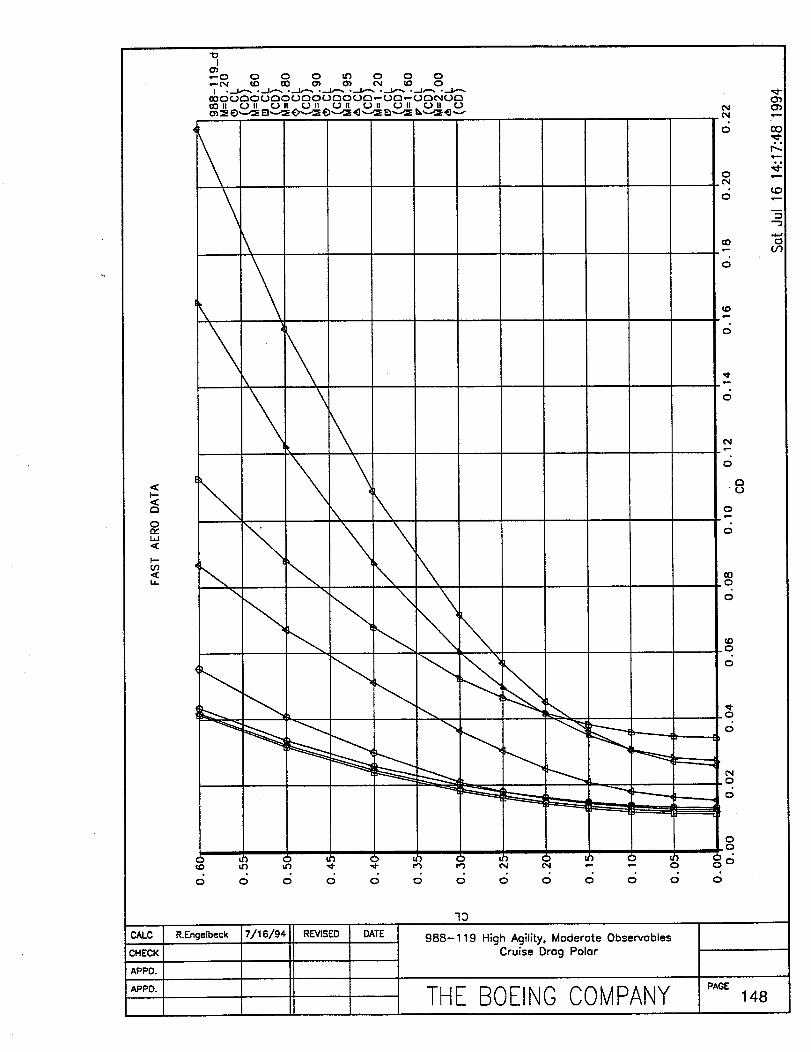
1--,<a
0m.,"I,I
I--Oq
i.
\\
'....
\\\ \\
"_ ",,
0
0
0
O0
0
c[}
; (.,.)
0
5
O0.0
0
0
0
_ r-----..---.-_
0
0,0
c; c; 6 c; 6 c; 6
R.Engelbeck
19
988-119 High Agility, Moderate ObservablesCruise Drag Polar
THE BOEINGCOMPANY "'_ _48
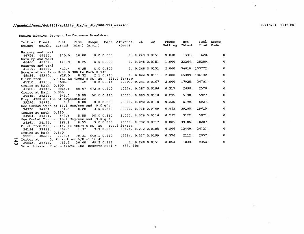
//gandalf/user/deb9848/agility_dir/mr_dir/988-119_mission 07/16/94 1:42 PM
CD
Design Mission Segment Performance Breakdown
Initial Final Fuel Time Range
Weight Weight Burned (min.) (n.mi.)
Mach Altitude CL CD
(feet)
0. 0.248 0.0151
0. 0.248 0.0151
0. 0.248 0.0151
40226. 0.287 0.0186
20000 0.090 0.0118
20000 0.090 0.0118
20000 0.715 0.0768
20000 0.079 0.0116
0.702 0.0717
0.272 0.0185
0.317 0.0209
0.248 0.0151
635. ibs
Warm-up and taxi46756 46486. 270 0 i0.00 0.0 0.000
Warm-up and taxi
46486 46369. 117 9 0.25 0 0 0.000
Warm-up and taxi46369 45936. 432 4 0.25 0 0 0.300
Acceleration from Mach 0.300 to Mach 0.945
45936 45310 626 5 0.32 2 1 0 945 0. 0.044 0.0111
Climb from 0.0 ft. to 42902.8 ft. at 228.7 ft/sec
45310 43700 1609 7 1.62 i0 8 0 844 42903. 0.241 0.0167
Cruise at Mach 0.800
43700 39845 3855 5 88.07 672 9 0 800
Cruise at Mach 0.880
39845. 39296 548 7 5.55 50 0 0 880
Drop 4300.00 ibs of expendables39296. 34996 0.0 0 00 0 0 0 880
One Combat Turn at 18.1 deg/sec and 9.0 g's
34996. 34904 91 5 0 28 3 0 0 880
Cruise at Mach 0.880
34904. 34361 543 6 5 55 50 0 0 880
One Combat Turn at 18.1 deg/sec and 9.0 g's
34361. 34194. 166 9 0 55 3 0 0 880 20000
Climb from 20000.0 ft. to 48574.6 ft. at 199.2 ft/sec
34194. 33331. 862 5 1 37 9 9 0 830 48575
Cruise at Mach 0.840
33331. 30552. 2779 5 79 31 640 1 0 840 49934
Loiter at 0. ft and max L/D of 16.45
30552. 29763. 788 3 20.00 69.3 0 314 0
Total Mission Fuel = 12693. ibs Reserve Fuel =
Power Net Fuel Error
Setting Thrust Flow Code
0.040 1331. 1620. 0
1.000 33264. 28289. 0
2.000 54610. 103772. 0
2.000 65309. 136132. 0
2.000 17925. 34701. 0
0.317 2698. 2570. 0
0.235 5190. 5927. 0
0.235 5190. 5927. 0
0.863 39185. 19615. 0
0.232 5122. 5871. 0
0.806 39185. 18207. 0
0.806 12449. 24121. 0
0.376 2112. 2057. 0
0.054 1833. 2354. 0
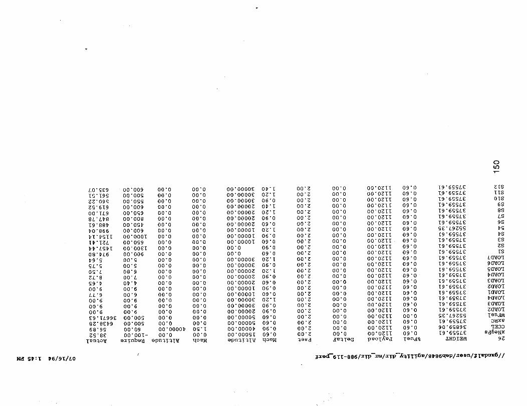
L0"£_9
I£'I9£gg'O9g
g£'619O0"IL9
8L'L#8
I9"88#
#0"866
#I'#£II
I#'IZL
##'L£#I08 " #L6
#9"_
£L'£
O$'LgL'8
00"6
LL'9
00"6
00"6
00"6
E9"IL99_
8Z'8_#9
68"9_
gg'8E
Ten_ov
00"009
00"00£00"0££
00"009
00"0£9
00"008
O0"OS#
00"009
O0"O00I
O0"Og9
O0"OOEI
00"006
O0"g
00"_
08"9
O0"L
0#'#
00"6
00"9
00"6
O0 6
O0 6
O000g
O0 00£
O0 09
O0 O01-eaTnbeH
00"0
00"0
00"0
00"0
00"0
00"0
00"0
00"0
00"0
00"0
00"0
00"0
00"0
00"0
00"0
00"0
00"0
00"0
00"0
O0 0
O0 0
O0 0
O0 0
O0 0
O0 0000#
00"0
epn_3_l_
00"0
00"0
00"0
00"0
00"0
00"0
00"0
00"0
O0 "0
00"0
00"0
00"0
00"0
00"0
00"0
00"0
00"0
00"0
00"0
00"0
O0 0
O0 0
O0 0
O0 0
0£ I
O0 0
qoe_I
O0"O000E
O0"O000E
O0"O000E
O0"O000g
O0"O000g
O0"O000g
O0"O000g
00"0000I
O0"O0001
O0"O0001
00"0
00"0
O0"O000E
O0"O000E
00"0000_
O0"O000Z
O0"O000g
O0"O0001
O0"O0001
O0"O000E
O0"O000E
O0"O000g
00"0000_
00"0000_
00"0000#
00"000_I
epnq/_TV
0#'I
0g'l
06 0
O# I
0g I
06 0
09 0
0g I
06 0
09 0
06 0
09 0
0g I
O6 0
0g l
06 0
O9 0
06 0
09"0
Og'I
06"0
06"0
09"0
09"0
06"0
09"0
qoeI4
O0"g
O0"g
O0"g
O0"g
O0"g
O0"g
O0"g
O0"g
O0"g
O0"g
O0"g
O0"g
O0"g
O0"g
O0"g
O0"g
O0"g
O0"g
O0"g
O0"g
O0"g
O0"g
O0"g
O0"g
O0"g
O0"g
_eSd
0LO'I'--"
O0 0O0 0
O0 0
O0 0
O0 0
O0 0
O0 0O0 0
O0 0
O0 0
O0 0
O0 0
O0 0O0 0
00"0
00"000"0
00"0
00"000"0
00"0
00"0
00"000"0
00"000"0
O0"OglI
O0"OgII
O0"OgII
O0"OgII
O0"OglI
O0"OglI
O0"OgII
O0"OgIl
O0"Ogll
O0"OgII
O0"OgII
O0"OglI
O0"OgII
O0"Ogll
O0"OgII
O0"Ogll
O0"OgII
O0"OgII
O0"OglI
O0"Ogll
O0"OgII
O0"OgII
O0"OgII
O0"Ogll
O0"OgII
O0"OgIl
p_oT_d
09
09
09
09
09
09
0
0
0
0
0
0
09 0
09 0
09 0
09 "0
09 "0
09"0
09 "0
09 "0
09 "0
09 "0
09"0
09 "0
09"0
09 "0
09"0
09"0
00"0
09"0
09 "0
09 "0
Ten._%
19"6ggL_
I9"6£SLE
I9"6£gLE
I9"6S_LE
19"6G£LE
I9"6£SLE
I9"6_£LE
SE'L9g££
19"6SSLE
19"6£SLE
19"6£gLE
I9"6_£LE
19"6_LE
19"6_/E
19"6G_LE
I9"6G_LE
I9"6_GLE
19 6_LE
19 6GSLE
I9 6S_LE
I9 6G_LE
I9 6SGLE
_E L9Z££
I9 6_£L_
90 6£89E
19 6£SLE
_HDI_M
ZIS
IIS
OIS
6S
8S
LS
9S
#g
#S
ES
gS
IS
LQvoq
90voq
gQ_Oq
E_Oq
g_Oq
I_VOq
EO_Oq
gO_Oq
TenalM
OHxe
q_OO
Sd6eNX
9E
_ _:I _6/91/L0 ; _x_d"611-886/xTP--xuz/x;P'-KW_T_5_/BPB6qeP/xesn/_I_PU_5//
Model 988-118, Medium Agility - Low Observables
As a medium agility, low observable vehicle Model 988-118 is a moderate gross weight single place,subsonic delta wing design powered by two turbojfan engines of 30,830 pounds augmented thrusteach. The external general arrangement, shown on drawing ASC 988-118-1, is characterized by themoderate leading edge sweep of thirty-eight (38) degrees, nested lower forebody inlet apertures, _ullspan trailing edge elevons, and upper body mounted thrust vectoring exhaust nozzles. The wingleading edge incorporates large powered slats that are used to augment maneuver performance.
Control effectors include the yaw thrust vectoring exhaust nozzles with _+45degrees of deflection,Yaw Vane pairs on the upper and lower surface integrated with the nozzle, and four elevons per semi-span. Elevons are single panel at the most inboard position,with the two outboard panels being spliton the wing reference plane.
Inlets are integrated/nested with the lower forebody, and exhaust nozzles are located side-by-side onthe upper aft fuselage. Yaw Vane pairs are integrated with the nozzles and on the lower aft body.
The interior layout, shown on inboard profile drawing ASC 988-118-2, accommodates the crew,subsystems, weapons and propulsion system within a low profile body shape. The forebody isconventional in arrangement and includes avionics, crew station, gun system, and subsystems.Center body contents are inlet system, weapons bay, and main landing gear. The aft body providesengine and exhaust system accommodation.
Propulsion system installation features consist of the nested external compression fixed ramp inlets,each feeding a long vertical offset inlet diffuser running over the weapons bay to an engine face.
The exhaust system includes augmentor spray bars, and a fully offset duct to nozzle exit plane. Theduct turns through a circular bearing/rotation plane to direct exhaust gas out the nozzle aperture. Asignificant and challenging risk issue is presented here in this concept of making the rotating nozzlesystem augmentor.capable. A discussion of this issue is contained in Section 7.0, Areas of HighTechnical Risk.
Nozzle concept is that of a variable throat SERN type that utilizes the upper aft deck as the expansionsurface.
All fuel is contained in the main wing panel outboard of the side of body. Provision would be made toprotect get-home fuel in each wing tank.
151

/
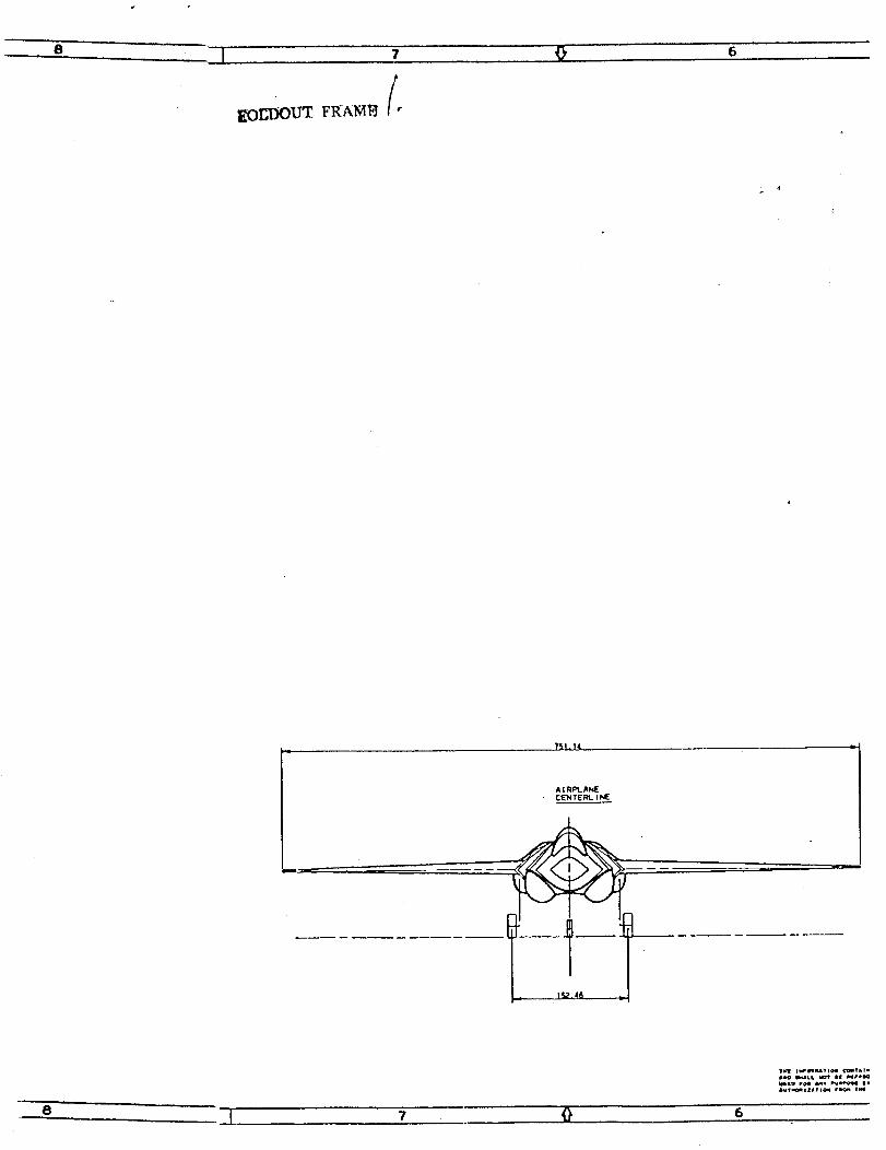
B..... l
7 6
'_Sl. 14
A I RAkqEC_"_IT E Iql,. I hliE
IhUt_I_ATIQII fm_,m VII!
8 ] "l _ 6

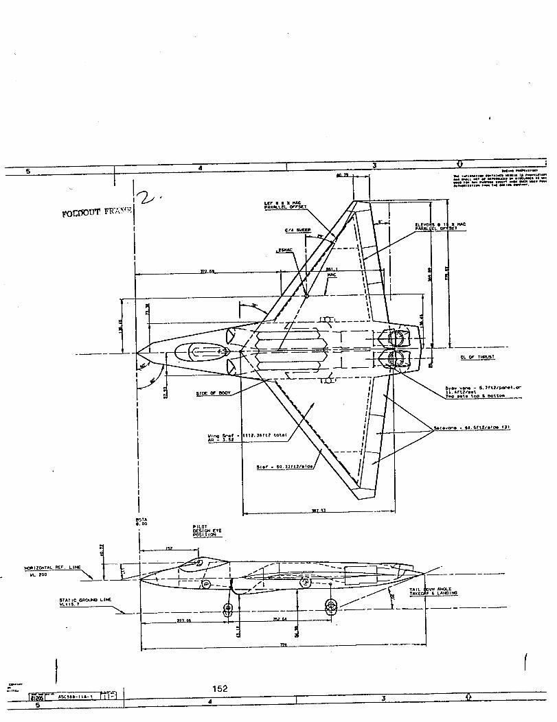
5
$0 I!
!
I tI
HO_ I Z_TAL REF" L IHI __-_.
STATIC GROUNO LINEVLIIS. 7
J5
SlOE OF
I
Slef _ SO.33ft211t_
PILOTDESIGN EYEPOSITION
t_? - :
/°
F_ AHO4-ELA_I_
152,, T'- 3

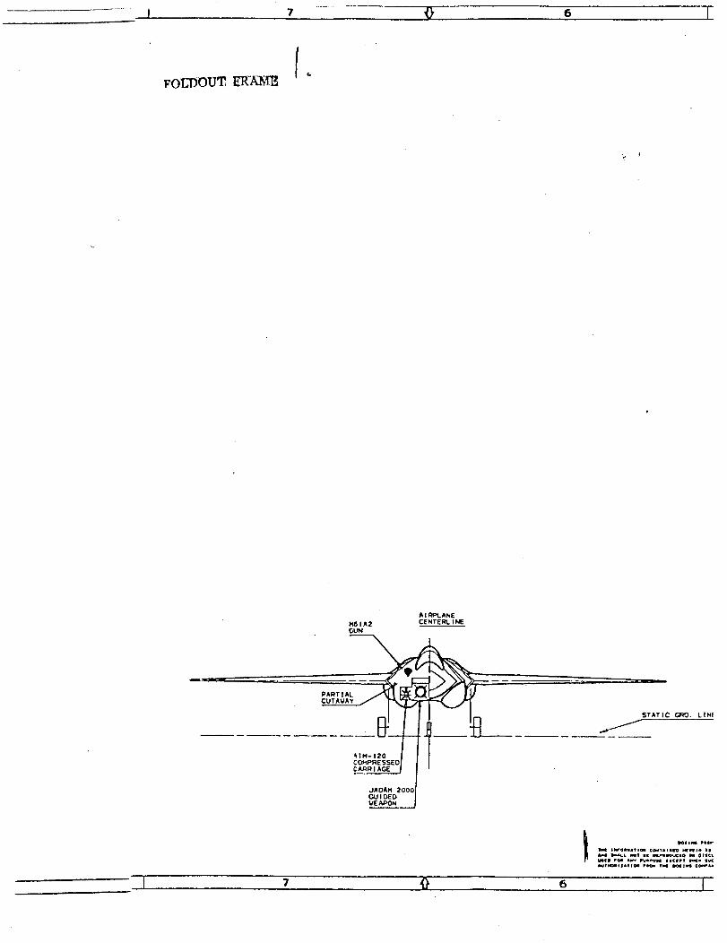
,,j 7 _, e I
_OUDOUT ER'ANm
'I
A I RPL.ANE
M6 I A2 CENTEI_ I NE
co_m_ssEol I I
,+ool'GUIDED I
VEAPON I
STATIC' GI_. LINE
7 9 6 I

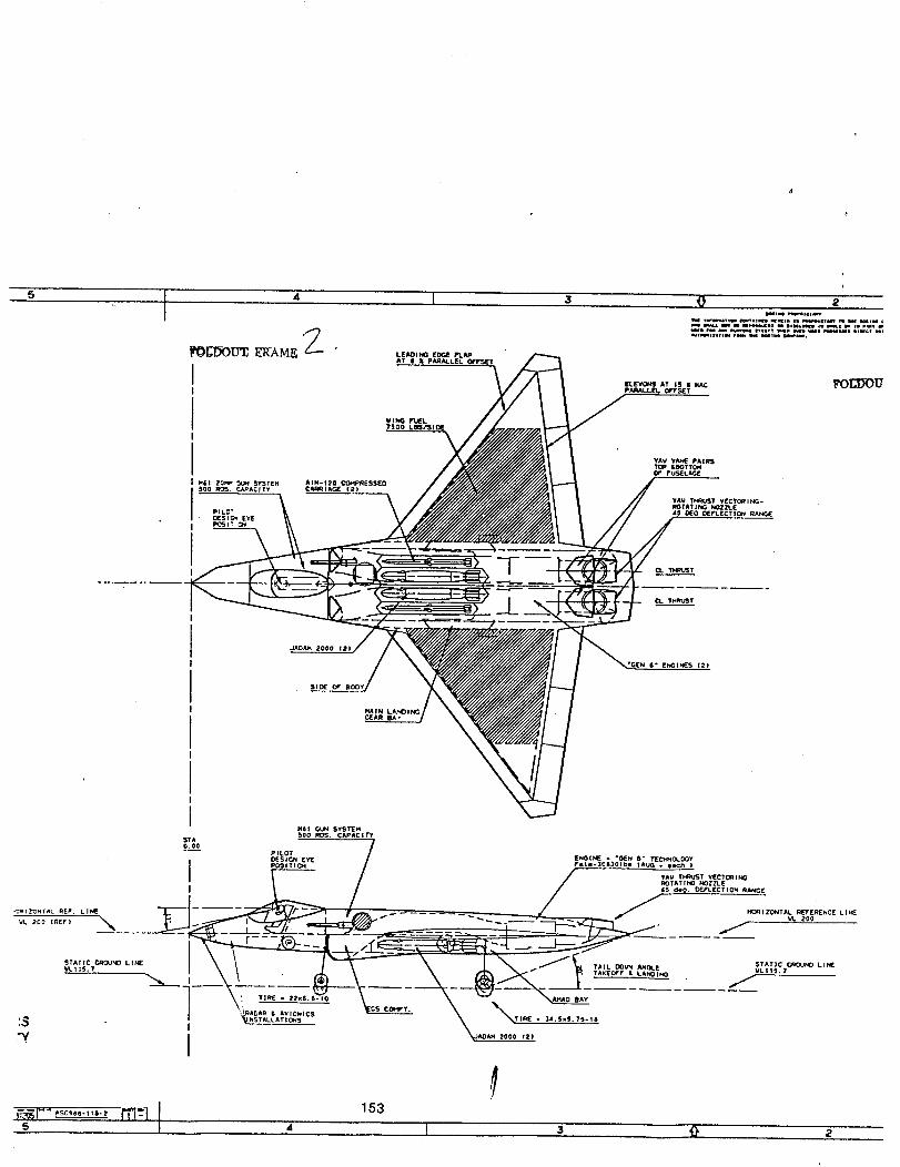
5 I 3
ELEVONS AT 15 • I(ACPkqALLE / OFFSET
2
FUl I GL_ SYSTEH
STA 500 ROS. CAPACITY
ooo r--- / /*-- PILOT
DESIG_I EYE ENGINE o °OEN 6" TIEC_I_O_.OOYPI_JITI_I Fl|l-308301bl IAU_ . e_ch )
• YA_/ THRUST V(CTCltI_ROTAT I_1_ _OZZLE
":_IZ_NT_L REF. LI_ _.p_ .._ ..... _ HC_IZ_TAL REVERENCE LI_E
VLIIS.? I _ • TAKEOFF • LAN01_ VLII_S.?
"_---_ \_ - EL _ \_____d____L_ -- ' /CS COI_T.
_s ,I '_:,,._,_, _ _ \,,,_.,,.,.,.,.,,I _AOA. ,ooo ,_)
s " I z 0 •


GROUP WE]GI rr STATEMENT
MISSION: Multi-role Mission
MODEL: 988-118 MedA/LO
WNG
BODY
MAIN GEAR
NOSEGEAR
AIR INDUCTION
ENGINE SECTION
YAW VANES
TOTAL STRUCTURE
ENGNES
AMADS
ENGINE CONTROLS
STARTING SYSTEM
FUEL SYSTEM
VECTORING NOZZLES
TOTAL PROPULSION
FUGHT CONTROLS
APU
INSTRUMENTS
HYDRAULICS
ELECTRICAL
AVIONICS
ARMAMENTFURNISHINGS & EQUIPMENT
AIR CONDITIONING
ANTI-ICE
LOAD AND HANDLING
WEIGHT
(LB)
6931
7618
1288
330
1145
293
294
17899
3352
200
40
80
1020
1412
6104
1380
210
270
506
618
1700
204
371
658
10
10
TOTALRXEDE-CXJlPMENT 5938
_E_'vfPTY 29941
CFEW
CREW EQUIPMENT
OIL & TRAPPED OIL
TRAPPED FUEL
GUN INSTALLATION
LAUNCHERS__JECTORS
AMMO CASES
NE_EXP USEFUL LOAD
OPERATING 14_GHT
215
40
100
214
252
70O
90
1611
31552
4990
110
14248
50900
BO_BS_ISSlLESEXPENDABLE
FUEL
NOSE STATION 0 IN
WING MAC 260 IN
LEMAC 373 IN
BODY LENGTH 710 IN
BODY STATION PERCENT MAC
499
417
490
225
341
574
638
452
574
501
375
536
488
654
574
542
621
180
532
396
200
236
221
246
130
417
350
457 32.2%
175
175
546
488
236
393
236
347
451 30.1%
GROSS _
394
236
488
455 31.6%
SpreadSheet: 988-118 WT. STATEMENT 15 4 5 / 6 / 9 4

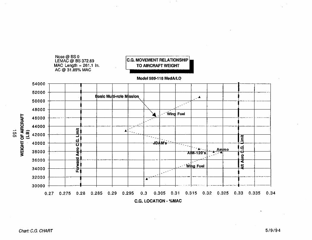
54000
52000
50000
48000
46000
44000
.ooo
4000038000
36000
34000
32000
30000
0.27
Nose @ BS 0LEMAC @ BS 372.69
MAC Length = 261.1 In.AC @ 31.85% MAC
Model 988-118 MedA/LO
l laslc MuI If-role M ssio_/,_ . .&
_.-"Wln_ Fuel
'r"_M',, ....ul.#l
" ""•--- Amino
AIM-120's _"• ":'_
.-"Wllg Fuel
0.275 0.28 0.285 0.29 0.295 0.3 0.305 0.31 0.315 0.32 0.325 0.33
C.G. LOCATION - %MAC
0.335 0.34
Chart: C.G. CHART 5/9/{) 4
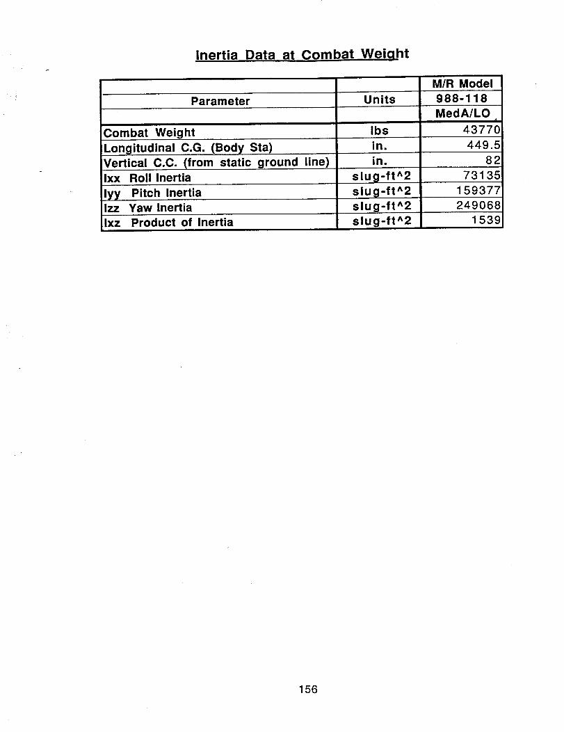
Inertia Data at Combat Weiqht
M/R Model
Parameter Units 988-118
Combat Weight
Longitudinal C.G. (Body Sta)
Vertical C.C. (from static ground line)
Ixx Roll Inertia
Ibs
in.
in.
slug-ft^2
slug-ft^2lyy Pitch InertiaIzz Yaw Inertia slug-ft^2
Ixz Product of Inertia slug-ft^2
MedA/LOd
43770
449.5
82
73135
159377
249068
1539
156
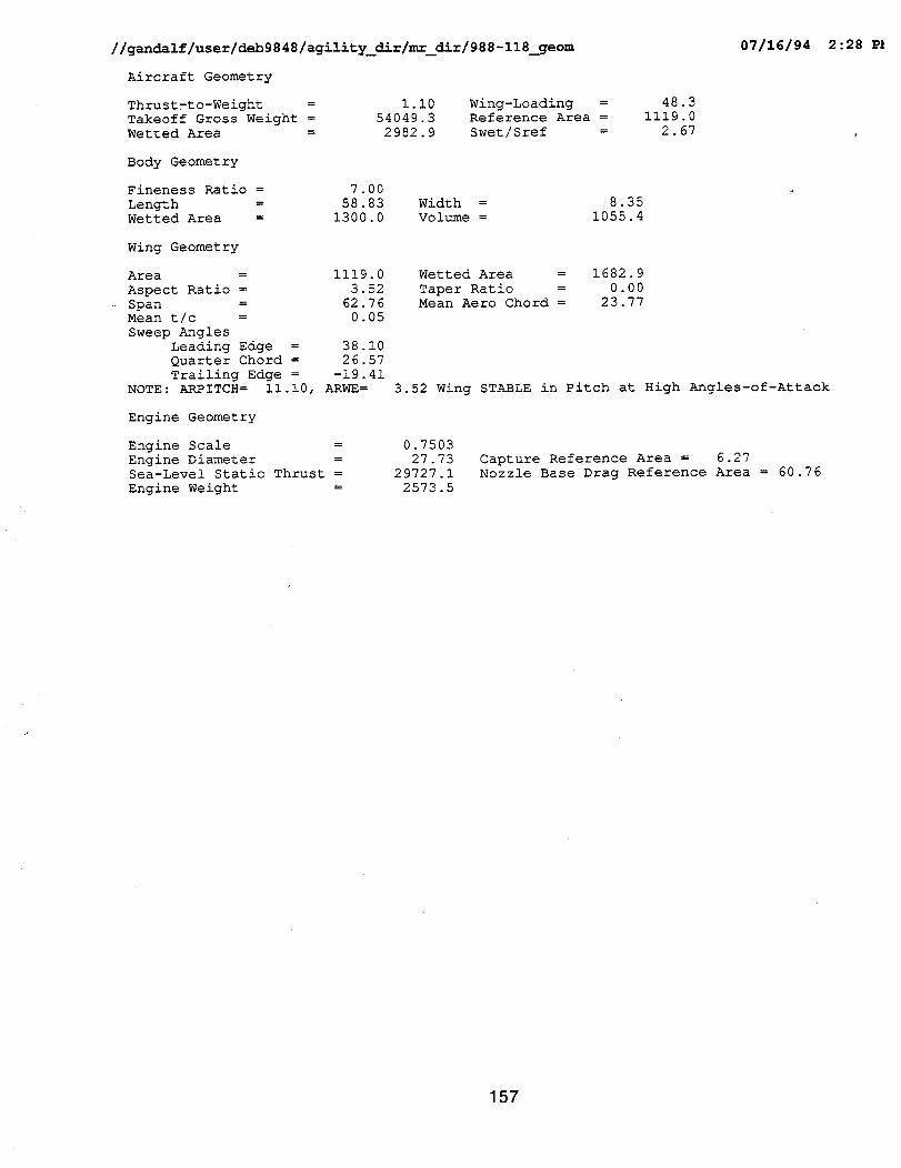
//gandalf/user/deb9848/agility_dir/mr_dir/988-118_geom 07/16/94 2:28 P}
Aircraft Geometry
Thrust-to-Weight =
Takeoff Gross Weight =
Wetted Area =
I.I0 Wing-Loading =
54049.3 Reference Area =
2982.9 Swet/Sref =
48.3
1119.0
2.67
Body Geometry
Fineness Ratio = 7.00
Length = 58.83 Width =
Wetted Area = 1300.0 Volume =
8.35
1055.4
Wing Geometry
Area = 1119.0
Aspect Ratio = 3.52
Span = 62.76
Mean t/c = 0.05
Sweep Angles
Leading Edge = 38.10
Quarter Chord = 26.57
Trailing Edge = -19.41
NOTE: ARPITCH= ii.i0, ARWE=
Wetted Area = 1682.9
Taper Ratio = 0.00
Mean Aero Chord = 23.77
3.52 Wing STABLE in Pitch at High Angles-of-Attack
Engine Geometry
Engine Scale = 0.7503
Engine Diameter = 27.73
Sea-Level Static Thrust = 29727.1
Engine Weight = 2573.5
Capture Reference Area = 6.27
Nozzle Base Drag Reference Area = 60.76
157
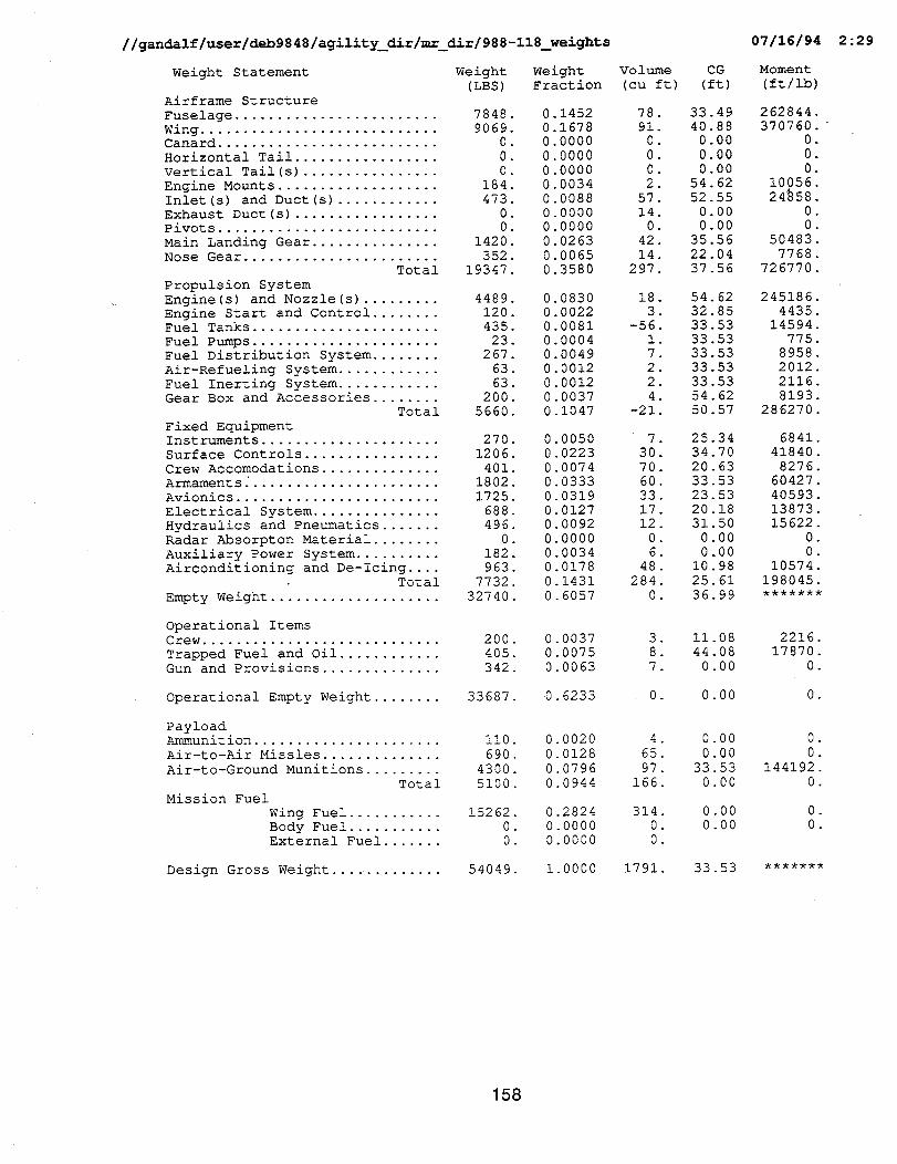
//gandalf/user/deb9848/agility_dir/mr_dir/988-118_weights 07/16/94 2:29
Weight Statement Weight Weight Volume(LBS) Fraction (cuft)
Airframe Structure
Fuselage ........................ 7848.
Wing ............................ 9069.Canard .......................... 0.
Horizontal Tail ................. 0
Vertical Tail(s) ................ 0.
Engine Mounts ................... 184Inlet(s) and Duct(s) ............ 473
Exhaust Duct(s) ................. 0Pivots .......................... 0
Main Landing Gear ............... 1420Nose Gear ....................... 352
Total 19347
Propulsion System
Engine(s) and Nozzle(s) ......... 4489Engine Start and Control ........ 120Fuel Tanks ...................... 435
Fuel Pumps ...................... 23Fuel Distribution System ........ 267
Air-Refueling System ............ 63
Fuel Inerting System ............ 63Gear Box and Accessories ........ 200
Total 5660
Fixed EquipmentInstruments ..................... 270
Surface Controls ................ 1206
Crew Accomodations .............. 401Armaments_ ...................... 1802
Avionics ........................ 1725
Electrical System ............... 688Hydraulics and Pneumatics ....... 496
Radar Absorpton Material ........ 0Auxiliary Power System .......... 182
Airconditioning and De-Icing .... 963.Total 7732.
Empty Weight .................... 32740.
0.1452
0.16780.0000
. 0.0000
0.00000.0034
0.0088
0.00000.0000
0.0263
0.00650.3580
0.08300.0022
0.00810.0004
0.00490.0012
0.00120.0037
0.1047
0.0050
0.0223
0.00740.0333
0.0319
0.01270.0092
0.00000.0034
0.0178
0.1431
0.6057
Operational ItemsCrew ............................ 200.
Trapped Fuel and Oil ............ 405.Gun and Provisions .............. 342.
0.00370.0075
0.0063
Operational Empty Weight ........ 33687. 0.6233
78
910
0
02
57140
42
14
297
18
3-56
17
2
24
-21
7 .
30.70.
60.
33.17.
12.
0.6.
48.
284.
0.
3.
8.
7.
0 .
CG
(ft)
33.49
40.880.00
0.00
0.0054.62
52.55
0.000.00
35.56
22.0437.56
54.6232.85
33.5333.53
33.5333.53
33.53
54.62
50.57
25.3434.70
20.63
33.5323.53
20.18
31.500.00
0.00
10.9825.61
36.99
11.08
44.08
0.00
0.00
Moment
(ft/ib)
262844.
370760."0.
0.0.
10056.24_58
00
504837768
726770
2451864435
14594775
89582012
2116
8193286270
6841
41840
8276
6042740593
1387315622
0
010574
198045
2216.17870.
0.
0 .
PayloadAmmunition ...................... ii0. 0.0020 4. 0.00 0.
Air-to-Air Missles .............. 690. 0.0128 65. 0.00 0.
Air-to-Ground Munitions ......... 4300. 0.0796 97. 33.53 144192.Total 5100. 0.0944 166. 0.00 0.
Mission Fuel
Wing Fuel ........... 15262. 0.2824 314. 0.00 0.Body Fuel ........... 0. 0.0000 0. 0.00 0.External Fuel ....... 0. 0.0000 0.
Design Gross Weight .... ......... 54049. 1.0000 1791. 33.53
158
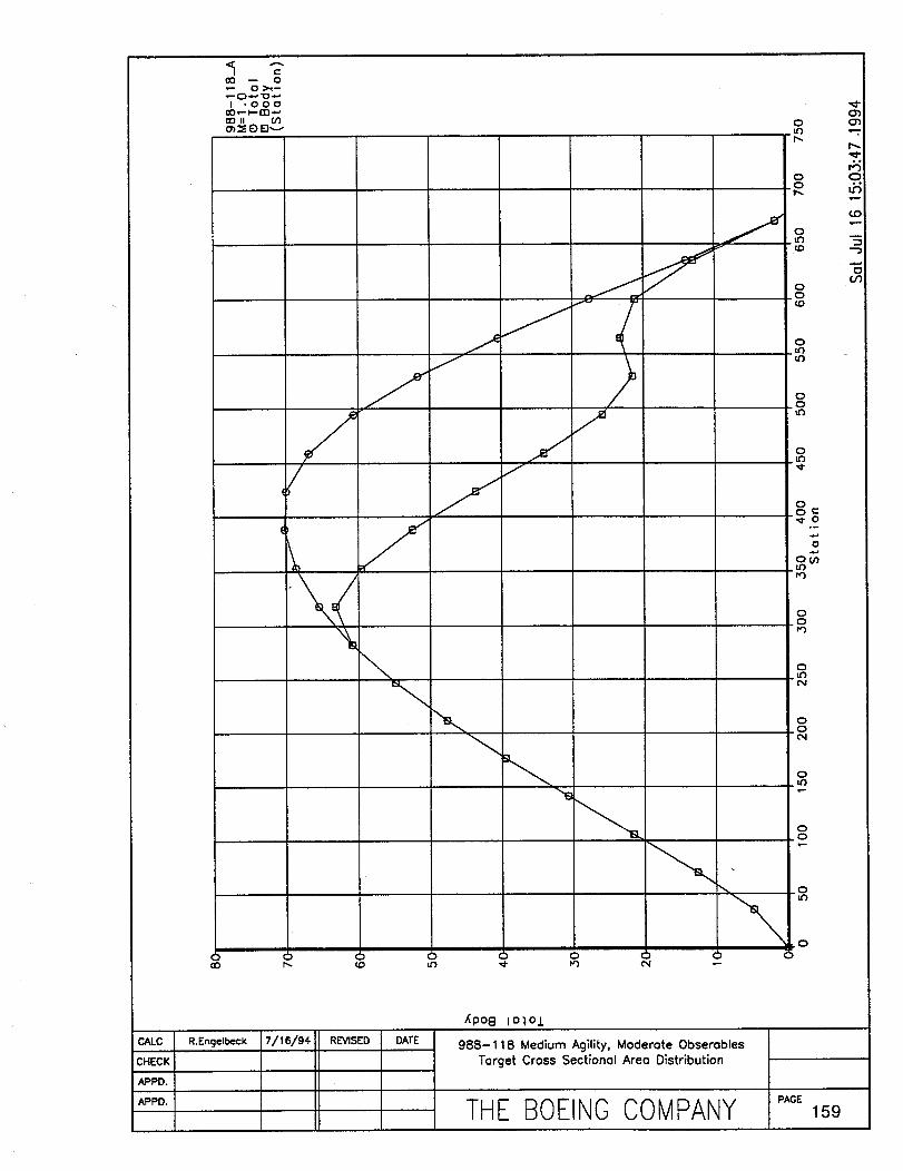
0o -- _o•"- Oh_ C)"-" "O"
I "OOO00 _ _-- (D"-'00 II _') 0
LF_C_
CALC
c";Co;IAPPD.
//
\
//
zJ
00 r'- {D Lr}
\()
R.Engelbeck
_PO8 IOIO_
988-118 Medium Agility, Moderate 0bserables
Target Cross Sectional Area Distribution
I"
LO,r--
O.t.'3
(_O
.O(D
O
00
0LO
0
0_0rO
0
0_0
0LO
0.0
0
THE BOEINOCOMPANY ,,,o_1_9
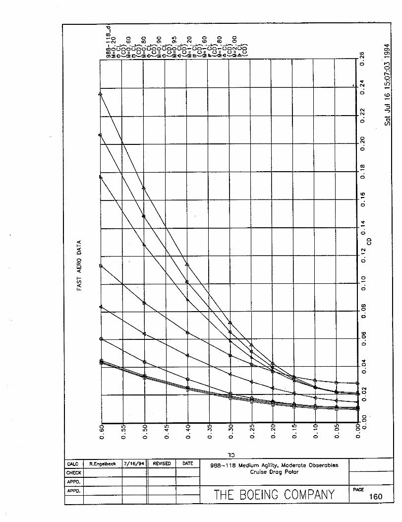
r_
0n-bd
bO<
I CHECAL:K
APPD. I
APPD. I
"lOI
_0•"-0 0 0 0 ur) 0 0 0 0
QOCN
O
_i£N
O
O
O(N
O
00
O
\\ \\
,,--i
0
O
q:)
R.Engelbeck
73
988-118 Medium Agility,Moderate ObseroblesCruiseDrag Polar
THE BOEINGCOMPANY "_ 16o

//gandalf/user/deb9848/agility_dir/mr_dir/988-118_mission 07/16/94 2:27 PM
Design Mission Segment Performance Breakdown
Initial Final Fuel Time Range Mach Altitude
Weight Weight Burned (min.) (n.mi.) (feet)
CL CD
---%
O_
Warm-up and taxi54049. 53737. 312.1 10.00 0.0 0 000 0. 0 220 0.0128
Warm-up and taxi53737. 53601. 136.3 0 25 0 0 0 000 0. 0 220 0.0128
Warm-up and taxi
53601. 53101. 499.8 0 25 0 0 0.300 0. 0 220 0.0128
Acceleration from Maoh 0.300 to Mach 0.935
53101. 52391. 710.1 0 31 2 1 0 935 0. 0 039 0.0095
Climb from 0.0 ft. to 44111.9 ft. at 216.7 ft/seo
52391. 50469. 1921.8 1 73 ii 7 0 847 44112. 0 218 0.0146
Cruise at Mach 0.800
50469. 46146. 4323.5 87 96 672 1 0 800
Cruise at Mach 0.880
46146 45514. 632.1 5 55 50 0 0 880
Drop 4600.00 ibs of expendables
45514 40914. 0.0 0 00 0.0 0 880
One Combat Turn at 18.1 deg/sec and 9.0 g's
40914 40830. 83.7 0.28 3.0 0 880
Cruise at Mach 0.880
40830 40203. 626.7 5.55 50.0 0.880
One Combat Turn at 18.1 deg/sec and 9.0 g's
40203 40045. 158.6 0.55 3.0 0.880 20000. 0.613 0.0517
Climb from 20000.0 ft. to 49737.7 ft. at 190.2 ft/sec
40045 38991. 1053.7 1.49 10.9 0.841 49738. 0.243 0.0161
Cruise at Mach 0.832
38991 35810. 3180.6 79.97 639.1 0.832 49984. 0.283 0.0182
Loiter at 0. ft and max L/D of 17.18
35810 34916. 894.3 20.00 68.8 0.311 0. 0.220 0.0128
Total Mission Fuel = 14533. ibs Reserve Fuel = 727. Ibs
41201. 0 259 0.0163
20000. 0 078 0.0101
20000. 0.078 0.0101
20000. 0.624 0.0534
20000. 0.069 0.0100
Power Net
Setting Thrust
0.040 1538. 1873
1.000 38452. 32702
2.000 63128. 119958
2.000 75423. 157065
2.000 19804 38343
0.323 3035 2888
0.234 5971 6828.
0.234 5971 6828.
0.696 45297 17937.
0.231 5899 6770.
0.673 45297 17306.
0.673 13877 26891.
0.375 2406 2334.
0.053 2059 2672.
Fuel Error
Flow Code
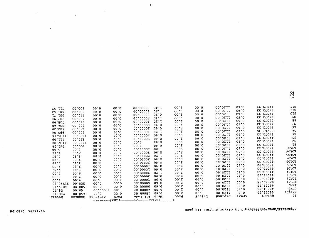
L_;" IIL
E# "18G
IL'IGG
#6" L#L
06 "_OL
8# " #E8
6g "g8_
#0"866
£I '_EII
60"gIL
8g'Z96
88 "_
II 9
L8 L
O0 6
66
O0 6
LE L
O0 6
O0 6
00"6
_I'SLL£E
8I'6I£9
0£'#£
0L'0EZ
I E D.3,O"_
00"009
O0"OOG
O0"OGG
00"009
00"0_9
00"008
O0"OG#
00"009
00"0001
00"0_9
O0 00El
O0 006
O0
O0
08 9
O0 L
O# #
O0 6
O0 "9
00"6
00"6
00"6
00"00£
00"00_
00"09
00"0_#-
e_ Tnbe_
O0 0
O0 0
O0 0
O0 0
O0 0
O0 0
O0 0
00"0
00"0
00"0
00"0
00"0
00"0
00"0
00"0
00"0
00"0
00"0
00"0
00"0
00"0
00"0
00"0
00"0
00"0000#
00"0
ePn_T_I_
00"0
00"0
00"0
00"0
00"0
00"0
00"0
00"0
00"0
00"0
00"0
00"0
00"0
00"0
00"0
00"0
00"0
00"0
00"0
00"0
00"0
00"0
00"0
00"0
O_'T
00"0
qoeN
00 0000E00 0000E
00 0000E
00 0000g
00 0000g
00 0000gO0 O000g
00"00001
00"00001
O0"O000I
00"0
00"000"0000E
00"0000E
O0"O000g
O0"O000g
00"O000g
O0"O000I
00"00001
00"0000E
00"0000E
00"0000g
00"0000_
O0"O000g
00"0000#
O0"O00gl
epn_!_IV
0#'I
0g'I
06"0
0#'I
0g'l
06"0
09"0
0g'I
06"0
09"0
06"0
09"0
Og'I
06"0
Og'I
06"0
09"O
06"0
09"0
0g'l
06"0
06"0
09"0
09"0
06"0
09"0
qo e[,.,I
O0"g
00"Z
00"g
00"g
00"g
00"g
00"g
O0 g
00 g
00 g
00 g
00 g
00 g
00 g
00 g
O0 g
00 g
00 g
00 g
00 g
O0"g
O0"g
00"g
O0"Z
O0"g
00"g
_esd
< ....... TEU!_ ....... >< ..... Te_!Ul ...... >
04(DT"
00"0
00"0
00"0
00"0
00"0
00"0
00"0
00"0
00"0
00"0
00"0
00"0
00"0
00"0
00"0
00"0
00"0
00"0
00"0
00"0
00"0
00"0
00"0
00"0
00"0
00"0
_e_TeG
O0"OgIl
O0"OgIl
O0"Ogll
O0"Ogll
O0"OgII
O0"OglI
O0"OZII
O0"Ogll
O0"OglI
O0"OglI
O0"Ogll
O0"OglI
O00glI
O00gIl
O00gll
O00ZII
O00gII
O00glI
O00gll
O00gII
O00gll
O00glI
O00gIl
O0"OZII
O0"Ogll
O0"OglI
peoT_ed
09"0
09"0
09"0
09"0
09"0
09"0
09"0
09"0
09"0
09"0
09"0
09"0
09"0
09"0
09"0
09"0
09"0
09"0
09"0
09"0
09"0
09"0
00"0
09"0
09"0
09"0
Ten_%
EE'EL0##
EE'EL0##
EE'EL0##
EE EL0##EE EL0##
EE EL0##
EE ELO#_
gE L9g_g
EE EL0##
EE EL0##
EE EL0##
EE ELO_#
EE EL0##EE EL0_#
EE ELO##
EE EL0_#
EE EL0_EE EL0##
EE _L0##
EE'EL0_#EE'EL0##
EE'EL0##
£E'L9E_
EE'ELO##
_6"IOEE#
EE'EL0_#
ZHDI3M
gIS
IlS
01S
6S
8S
LS
9S
#£
#S
ES
gS
IS
LO_Oq
9d_Oq
Gd_Oq
#O_Oq
Eq_oq
g_Oq
IG_Oq
_ovoq
EU_Oq
g_Oq
len_
O_xe
q_oo
Sd6ONx
9g
_ OE:E _6/91/L0 _xed-'SIl-BB6/X_P--Xm/x_P--_W_T_5_/B_86q_P/xesn/ITt'Pu_5//
7=0 C=r_ai &_
Comparisons
Air-to-Ground Designs
The Air-to-Ground designs for high and medium agility collapsed into the same design when themaneuvering devices were added. The Aircraft Design Synthesis results discussed in section 5.6concluded that when the maneuvering flaps were added, the aircraft thrust-to-weight required to meetboth levels of agility were exceed by the 6.5g sustained turn requirement. Further, the resultingreduction in aircraft thrust-to-weight made the thrust required to meet the lateral sideforce agilitymetrics the driver in aircraft engine size. Tripling the aircraft engine size to meet the lateral side forceagility matric would have a huge impact on aircraft weight and cost. The recommend approach for thenext design cycle would be to add large aerodynamic sideforce generators to the designs.
The flying wing configurations in general are extremely vulnerable to spiraling weight growth as thedesign matures since wing area growth is constrained by the LO philosophy, carder suitabilitygeometric constraints, and limited center-of-gravity flexibility.
Air-to-Air Designs and Multi-Role Design Drivers
Designs with significant Air-to-Air capability were driven to high T/W levels because of the maneuverrequirements. All the designs had low wing loading (W/S) because of their instantaneous turnrequirements. The combination of low wing loading and the resulting wing spans were judged to benear flutter boundaries between 3.5 and 4.5 aspect ratio.
The Impact of Carder Suitability
Adding the carder suitability features to the otherwise identical USAF customer added 14 to 17% tothe aircraft empty weight. The low wing Ioaclings, relatively high aspect ratio, and high aircraft thrust-to-weight ratios kept the single-engine rate of climb, catapult, and recovery performance boundaries.The biggest issue for.carder suitabilitywas the general size and weight of the aircraft and the adverseimpact it has on deck handling. Some issues remain conceming the impact of large inertias on therotation rates required to meet the 10 ft. sink requirement during a catapult launch, and the rotationrates required to accomplish a bolter. These issues were not addressed by the simplistic cardersuitability methods used to size the configurations.
The Impact of Observables Design Philosophy
The observables design philosophy as implemented here was to minimize the number of edges andsurfaces on the aircraft. One major impact of this philosophy is reduced maximum liftcapabilitybecause the flap system of tailless designs must be used for maneuver and trim requirements. Thisimpacts the instantaneous turn capability and carder launch and recovery speeds.
The Impact of Agility
Our design intent was to embrace the agility requirements from the outset of the study. Agility drovethe layout of the aircraft, the control system philosophy, and control surface sizing. In the case of theAir-to-Ground designs, agility would drive the propulsion system size unless an alternative sideforcegenerator concept were utilized.
The use of yaw thrust vectodng was key to the achievement of the lateral sideforce agility levels. Theuse of yaw vectoring was selected over conventional tails because of its effectiveness at high angles-of-attack and low speeds. In addition, thrust vectoring would probably neutralize the issue of
163
departure. Removal of the vertical tails on all configurationswas done to offset the impact in weightfrom the thrust vectoring system by elimination of the structural weight and drag penalties of thevertical tail. The added benefit of the elimination of the vertical tail is the reductionin side signature.Use of vertical tails would have required that they be canted to keep the side signature down resultingin the cross couplingof the yaw and pitch axis. The use of yaw vectoring without tails would eliminatethis undesirable cross coupling.
164
Design Interactions
Observables vs Agility
Design for agilitytends to favor concepts with more/larger control effectors, and low inertias. Designfor observabilitytends to drive the number of surfaces that produce a radar return down. Minimizingthe number of surfaces drives the designer to aerodynamically inefficient deltoid wings of low aspectratios. This aerodynamic efficiency drives the wing size up to partially offset the efficiency loss. Thelargerwing in turn makes the aircraft largerand heavier. The result is an aircraftdesignthat hasrelatively large inertias and fewer control eflectors. Design emphasis on low observables will be adetriment to agilityat a given level of maneuverability and missionperformance.
Carrier Suitabilityvs Agility
The Navy has traditionally been more stringent in the specification of maneuvering requirements thatutilize as much of an aircraft flight envelope as possible. The Navy expects their pilotsto fly to theedge of this envelope and consequently drives the designer to provide Level 1 flying qualities to themaximum limits of the operational envelope. The Navy requiries highdeparture resistance at highangles-of-attack sufficient to prevent loss of control while maneuvering close to and possible throughportions of the flight envelope where control authority traditionallybegins to diminish. The Air Forcewill typically accept limitersto avoid approaching CLmax boundaries throughoutthe maneuveringenvelope. The Air F-16 employs an angle-of-attack limitingschedule which shrinks the left boundaryof the energy maneuverability envelope significantlybeyond corner speed. Unique maneuverdevices are normallyfound on naval aircraftto ensure maximum maneuvering performance over a fullflight envelope. These devices usually take advantage of an already unique low speed, high liftsystem such as the maneuver flap. All of these features are positive contributionsto the agility of anaircraft.
A carrier suitable design is constrained in both weight and size withinthe operating limitationsof anaircraft carrier. Wing fold weight increases with span and tends to drive the wing span of the aircraftdown. Minimizing"the span minimizes roll inertia for any given weight helpingthe rollagilityof theaircraft. However, the decreased span also has an adverse effecton the roll control power necessaryto start and stopthe aircraft roll. The increase in aircraftweight to handle the structural loads andadditional equipment associated with carrier based operations overwhelm any positive aspects of theNavy designs resultingin aircraft designs less agile than their Air Force counterpartswith the samemaneuver and mission performance.
Air-to-Air vs Air-to-Ground Operational Mission Roles
Aircraft designed to the primarily subsonic Air Interdictionmission without any stringent supersonic orAir-to-Air maneuver requirements will typically have large low bypass engines and low aircraft T/W foroptimal cruise performance. Aircraft designed to meet the challenging Air-to-Air maneuverrequirements will typically have aircraft T/W greater than 1.0 and low bypass ratios. The keytechnology used in all the agility designs in this study is thrust vectoring. The benefit of thrustvectoring for agility is more effective on the Air-to-Air designs than the Air-to-Ground designs becauseof the greater T/W of the Air-to-Air designs.
165
Wave Drag Levels are Achievable
The specific excess power and sustained turn requirements are ambitious. These requirementsrepresent a ten percent improvement in maneuver capability over F-15 and F-14 fighter capability. Toobtain this maneuver capability the design philosophyfor wave drag is to work the cross-sectional areadistribution as hard as possible to minimize the transonicdrag rise and supersonic drag levels.Reduced wave drag will help minimize the engine size required for maneuver and minimize the fuelconsumed during supersonic cruise on the defensive counter air mission. Although ideal L-V Haackarea distributionsare targeted, figure shows a 30 to 44 percent conservatism in the final designs.This conservatism placed the Boeing designs comfortably within the demonstrated levels achieved bypast designs.
166
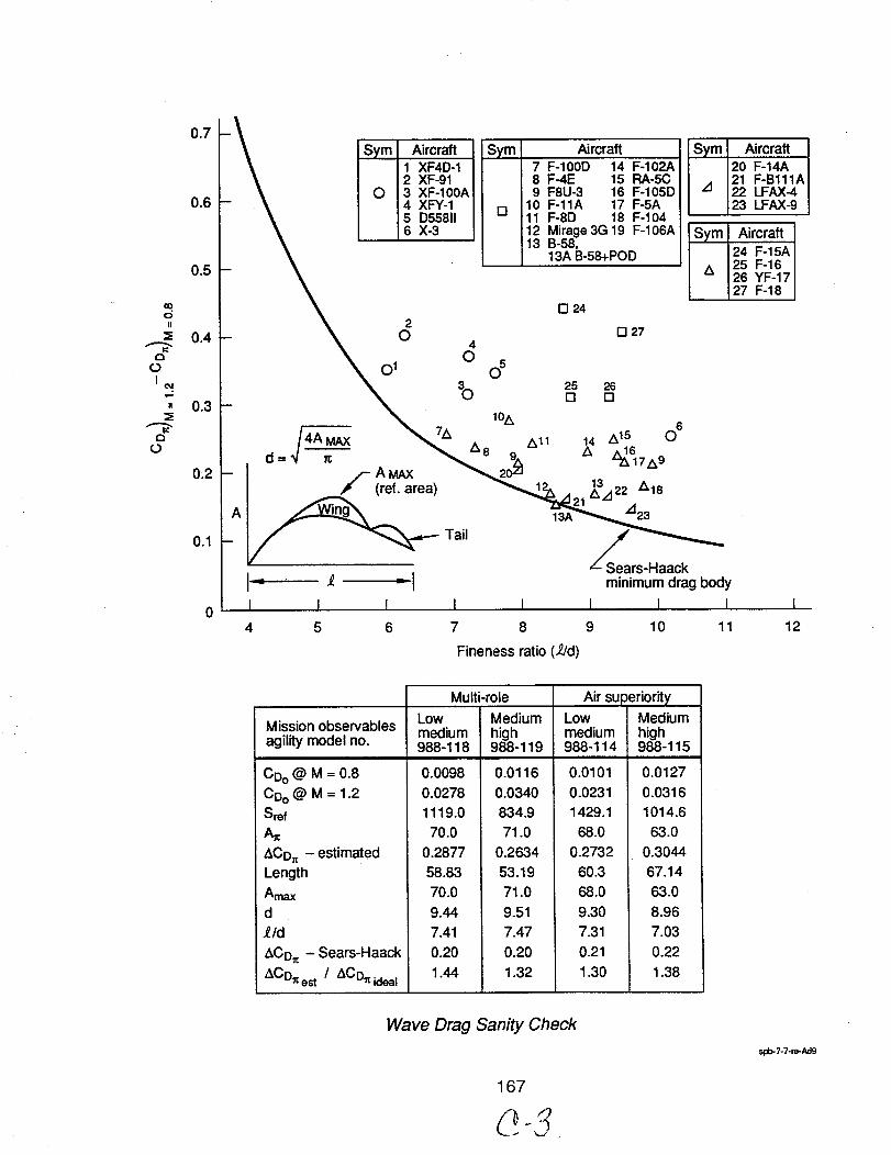
O
II
1:3
OI
04
II
,,,..pE3
O
0.7
0.6
0.5
0.4
0.3
0,2
0.1
Sym Aircraft1 XF4D-12 XF-91
O 3 XF-100A4 XFY-15 D558116 X-3
2O
40
01
b
(ref. area)
Tail
I1= _ =1
I I I I
4 5 6 7
Sym
D
Aircraft7 F-100D 14 F-102A8 F-4E 15 RA-5C9 F8U-3 16 F-105D
10 F-11A 17 F-5A11 F-8D 18 F-10412 Mirage3G19 F-106A13 B-58,
13A B-58+POD
n 24
[] 27
Sym
A
Sym
A
Aircraft20 F-14A21 F-B111A22 LFAX-4:23 LFAX-9
Aircraft24 F-15A25 F-1626 YF-1727 F-18
1%
All
25 26[] []
13A
14 Z_15 06
13/122 AlS
/t23
_Sears-Haack
minimum drag body
I I I
9 10 11
I
12
Fineness ratio (2/d)
Mission observablesagility model no.
CDo @ M = 0.8
CDo @ M = 1.2Sref
A=
ACD= - estimatedLength
AmaxdY/d
ACD= - Sears-Haack
ACD_ est / ACD_ ideal
Multi-role
Low Mediummedium high988-118 988-119
0.0098 0.01160.0278 0.0340
1119.0 834.970.0 71.0
0.2877 0.2634
58.83 53.1970.0 71.0
9.44 9.51
7.41 7.470.20 0.20
1.44 1.32
Lowmedium988-114
Air superiorityMediumhigh988-115
0.0101
0.02311429.1
68.0
0.273260.3
68.0
9.307.31
0.21
1.30
0.0127
0.03161014.6
63.0
0.304467.14
63.0
8.967.03
0.22
1.38
Wave Drag Sanity Check
167
spb-7-7-re-Ad9
6.0 Critical Assessment
Comparisons
Configuration Design
An assessment summary, figure 6.0-1, has been made for Models 988-115, -118 and -122/-123. Thegeneralized elements consider long term program issues such as growth capability in mission typeand payload size, as being critical to establishing design acceptability. If constrained to the singlemissionpayloads the practicality of these designs is suspect.
168
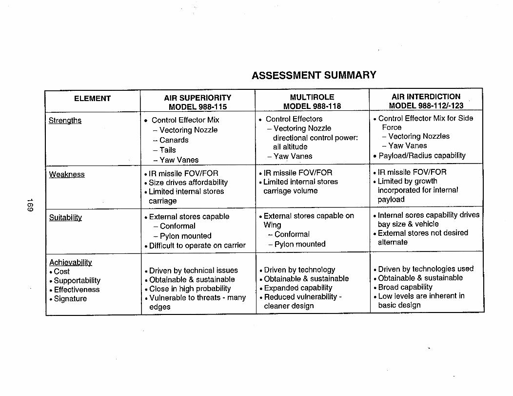
ASSESSMENT SUMMARY
...I.
03(D
ELEMENT
Strengths
AIR SUPERIORITY
MODEL 988-115
Control Effector Mix
- Vectoring Nozzle
- Canards
- Tails
- Yaw Vanes
MULTIROLE
MODEL 988-118
Control Effectors
- Vectoring Nozzle
directional control power:all altitude
- Yaw Vanes
AIR INTERDICTION
MODEL 988-112/-123
• Control Effector Mix for Side
Force
- Vectoring Nozzles- Yaw Vanes
• Payload/Radius capability
Weakness
Suitability
Achievability• Cost
• Supportability• Effectiveness
• Signature
• IR missile FOV/FOR
• Size drives affordability• Limited internal stores
carriage
• External stores capable
- Conformal
- Pylon mounted
• Difficult to operate on carrier
• Driven by technical issues• Obtainable & sustainable
• Close in high probability• Vulnerable to threats - many
edges
• IR missile FOV/FOR
• Limited internal stores
carriage volume
• External stores capable on
Wing- Conformal
- Pylon mounted
• Driven bytechnology• Obtainable & sustainable
• Expanded capability• Reduced vulnerability-
cleanerdesign
IR missile FOV/FOR
Limited by growth
incorporated for internal
payload
• Internal sores capability drives
bay size & vehicle• External stores not desired
alternate
• Driven bytechnologies used• Obtainable & sustainable
• Broad capability• Low levels areinherentin
basic design
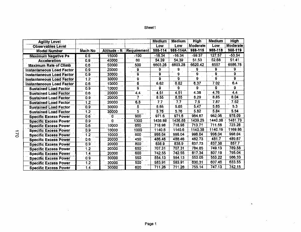
Sheet1
.,,jo
Agility LevelObservables Level
Model Number
Maximum Negative PsAcceleration
Maximum Rate of ClimbInstantaneous Load FactorInstantaneous Load FactorInstantaneous Load FactorInstantaneous Load Factor
Sustained Load FactorSustained Load FactorSustained Load FactorSustained Load FactorSustained Load FactorSustained Load FactorSpecific Excess PowerSpecific Excess PowerSpecific Excess Power
Mach No0.60.90.60.90.91.20.60.90.60.91.20.91.20.60.90.6
Medium Medium High Medium HighLow Low Moderate Low Moderate
Altitude-ft Requirement 988.114 988-114A 988-115 988-1t8 988-11915000 -100 -16.34 -16.34 -59.37 127.57 -53.5440000 60 54.39 54,39 51.53 52.68 51.4150000 500 6603.28 6603.28 6620.42 6557 6586.7820000 9 9 9 9 9 9300003000010000100002000020000200003000030000
00
10000
969
4.47
6.855
9OO1300650
96.62
94.518.557.7
5.655.76
971.61436.88718.98
6.62
4.518.557.7
5,655.76
971.61436.88718.98
99
6.379
4,388.297,9
5.475.82
964.871439.25713.71
7.02
4.768.857.875.855.84
962.061440.38711.58
6.4
4.48.047.525.3
5.54978.091481.73723.28
Specific Excess PowerSpecific Excess PowerSpecific Excess PowerSpecific Excess PowerSpecific Excess PowerSpecific Excess PowerSpecific Excess PowerSpecific Excess PowerSpecific Excess Power
1000
1.4 30000
1140.6 1140.6 1140.38 1140.190.9 100001.2 10000 600 998.04 998.04 998.04 998.04 998.040.6 20000 450 486.46 486.46 482.73 481.7 489.670.9 20000 800 838.9 838.9 837.73 837.38 857.71.2 20000 650 707.31 707.31 784.85 749.13 789.581.4 20000 600 742.55 742.55 817.34 807.19 795.040.9 30000 550 554.13 554.13 553.05 553.22 566.331,2 30000 500 583.91 583.91 630.31 607.46 633.55
600 711.26 711.26 755.14 747.13 742.15
1169.86
Page 1
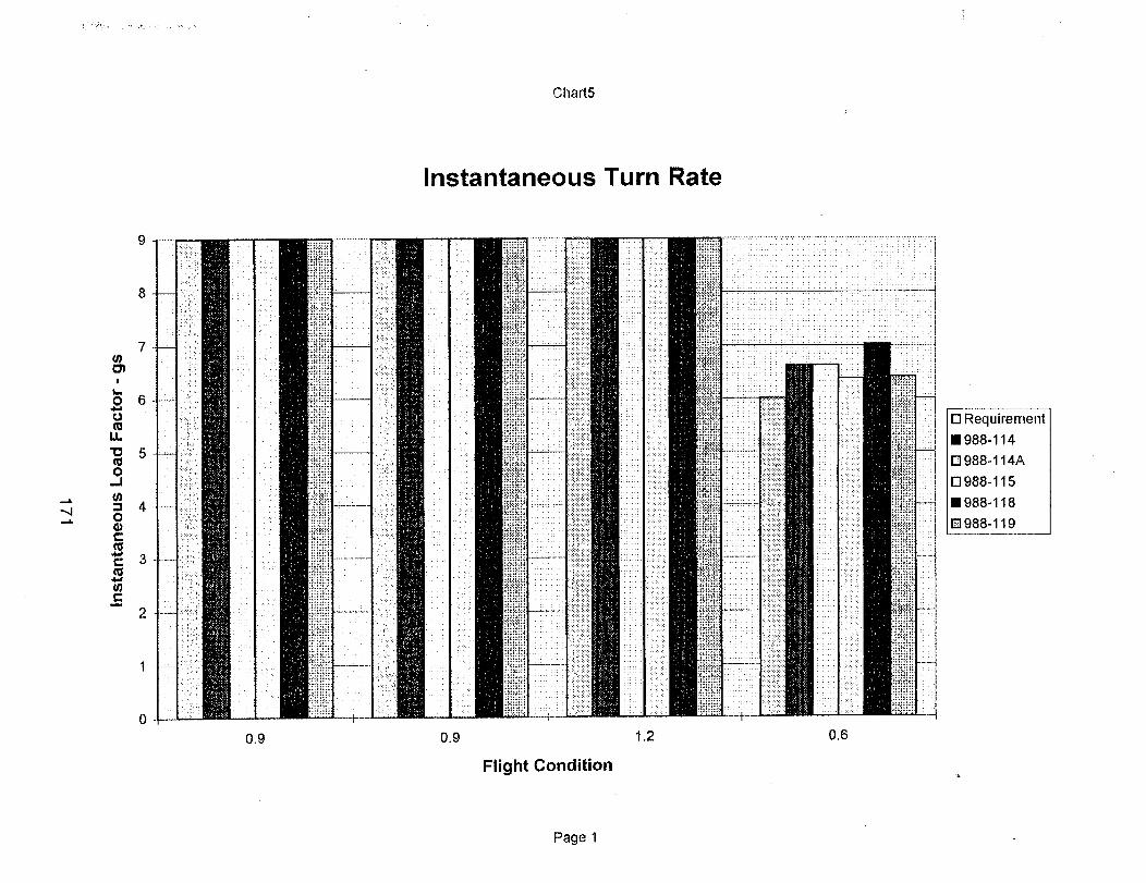
Chart5
Instantaneous Turn Rate
",4
9
8
7U)
I
t_
O 6
u.
"O 5_3O
..!
4O
3
¢n
2
----1'
• , =,
=.
-- L .
x:::::
li_!-!; ,';),.
i
. :.:.: :
!.iii_;
!taM'!!::=,
| i ::S:;
I .:.K!
Flight Condition
I
0.6
[] Requirement
I988-114
[] 988-114A
n988-115
I988-118
__988-119
Page 1
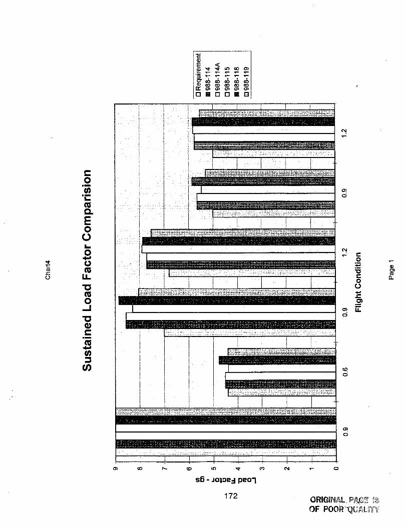
c-O
¢-0
U)ilmm
L_
E00L0
0
LL
0_J
_3
E <
°--
DBDOIB
o
o
o
c-o
am
in
c-o0
o)
n
o_c_
s5 - JO),Oe.-IpeO'l
172ORIGINAL P_ _OF POOR_!_U_LIT_ '
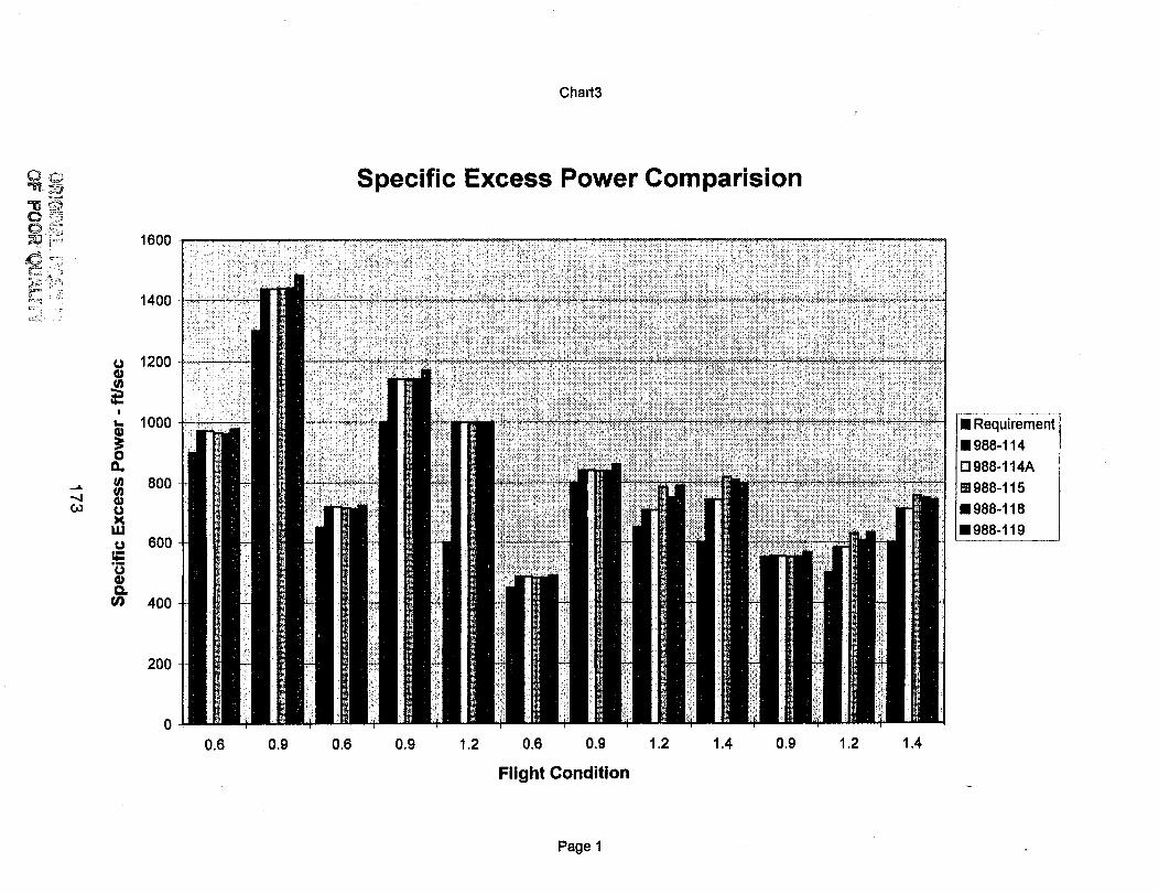
Chart3
1600
1400
Specific Excess Power Comparision
GO
U
!
t._
o0.,
LU
Q.00
1200
1000
8OO
6OO
400
=Requimment
E988-114
D988-114A
m988-115
=988-118
E988-119
200
0.6 0.9 0.6 0.9 1.2 0,6 0.9 1.2 1.4 0.9
Flight Condition
1.2 1.4
Page 1
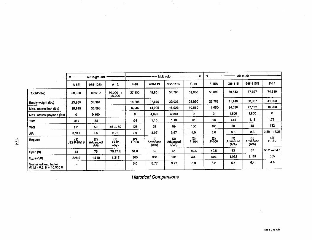
,-.k
TOGW (Ibs)
•"_-- Air-to-ground
A-6E
58,600
958-123N
80,910
• Multi-role
A-12 F-16
60,000 ---> 37,50080,000
16,285
6,846
0
988-119 988-119N
48,801 54,704
27,886 32,033
14,205 15,923
4,990 4,990
F-18
51,900
F-15A
50,000
Air-to-air
F-14
74,349
988-115 988-115N
59,549 67,397
31,746 36,367
24,026 27,192
1,800 1,800
Empty weight (Ibs) 25,980 34,961 23,050 26,768 41,353
Max. internal fuel (Ibs) 15,939 33,596 10,860 11,050 16,200
Max. internal payload (Ibs) 0 9,100 0 0 0
T/W .317 .34 .64 1.10 1.10 .61 .96 1.13 1.13 .72
W/S 111 50 45 _ 50 125
AR 5.311 3.5 3.75 3.0
Engines J52__2.)8A1B Adv(2a_)cedA/G
F:(42_2
(dry)
59
3.97
59
3.97
Ad:2a_)ced
(NA)
130
4.0
F! 4
82
3.0
F-%
58
3.8
(2)Advanced
(A/A)
58
3.8
(2)Advanced
(A/A)
132
2.58 _ 7.28
F! lo
Span (ft) 53 75 70.27 It 31.0 57 61 40.4 42.8 63 67 38.2 _ 64.1
Sref (sq ft) 528.9 1,618 1,317 300 830 931 400 608 1,032 1,167 565
- - 5.0 6.77 5.0 5.2 6.4 6.4 4.8Sustained load factor@ M = 0.6, H = 10,000 ft
6.77
Historical Comparisons
spb-8-7-re-Ad7
8.0 Fliaht Research Needs Assessment
The Value of Agility in Combat Effectiveness
The single largest uncertainty in designing an agile fighter is quantifying the value of agility in terms ofcombat effectiveness. In the absence of quantifiable measures of merit, the militaryhas beenreluctantto impose specific agilityrequirements on the aircraft designer. The aircraft industry isreluctantto develop methods or design aircraft to meet requirements their customer has notspecificallycalled out. Over the lastfew years, programs likeX-29, X-31, HARV and VISTA haveproducedresearch aircraftthat are arguably more agile than currentfighter aircraft. On those programswhere more than one aircraft exist (Skethe X-31), 1 vs 1 flightcombat simulationsand to beconducted with one research vehicle simulating a conventional fighter with the same basic flightcharacteristicsas the fully functionalresearch aircraft. In thisway the impact of agilityon combateffectiveness can be isolated from other flight characteristics. Issues concerning the impact of agilityon combat effectiveness in the M vs N scenario would best be quantified through flight combatsimulationsusing a collection of research aircraft against current inventory fighters. This would helpquantify the effect of number of adversaries has on the value of agility.
Control Effectors
Research needs to continue to develop new and creative methods to control aircraft. New challengessuch as lateral controlof tailless aircraft and concern for the signature characteristics of controls beingdeflected are only a subset of the research that needs to be conducted.
Wind tunnel tests need to be conducted to quantify the benefits of Tiperons against the heavy weightpenalties of attachment. Porous leading and trailing edge devices promise low RCS and reducedmechanical complexity, but more windtunnel testing is needed before the concept is proven anddesign information developed to effectively implement the concept into aircraft design. Leadingedge blowing, leading edge suction, and tangential wing blowing need more windtunnel databasedevelopment to prove the concepts, quantify the benefits, and determine the blowing requirementsand weight penalties. A database of windtunnel data needs to be developed for drag rudders as afunction of deflection and wing plantorm. A windtunnel database of the effectiveness of articulatingforebody strakes, nose strakes, chines, and other forebody shapes needs to be developed. All typesof forebody jet blowing, slot blowing, and suction need wind tunnel research to quantify theireffectiveness and how these concepts are impacted by forebody shape.
The primary attribute of all the designs produced in this design study is the radical amount of yawthrust vectoring used. Continued development of all thrust vectoring schemes with the objective ofproving the use of thrust vectoring as a primary control should be pursued vigorously.
Aerodynamics
Low signature requirements are driving the aircraft designer to simple tailless designs like the B-2 andA-12 configurations. This design philosophy would benefit from research into devices to counter theinherent inefficiencies of low aspect ratio wings with lotsof wetted area. Windtunnel testing of vortexflap concepts with sharp and semi-sharp leading edges need to be tested with various planformvariations, especially leading edge sweep. Variable camber or mission adaptive wing designs wereproven in the MAW and AFTI F-111 program but research into how to implement the concept withcomposite materials in an environment of emphasized low signature, lower weight, cost limitationsneeds to be researched. Success in CFD research into predictingtransition has direct impact on thesuccessfuldesign of natural laminarflow shapes. Natural laminar flow is one of the few technologiescapable of reducingparasite drag, a very important component of drag for aircraft with large wingsurfaces likethe B-2 and A-12. Research into methods to maintain a smooth surface in a dirty serviceenvironment and manufacturing issues need to be addressed for passive laminar flow concepts. Inaddition, reducing the maintenance requirements, weight, and cost of active laminar flow conceptsshould continue to be researched. Flight Testing samples, detailed CFD, and windtunnel testing ofporous lifting surface technology would help quantify the benefits of reduced shock strength andinstallationdrag penalties on the Mach capability of potential designs.
175
Propulsion
One of the early findings of this design study was the importance of engine technology level on theaircraft size and fuel requirements. These aircraft designs, relative to their contemporary counterparts,have long design mission radius requirements coupled with high thrust-to-weight ratios required fbrmaneuver. The resulting strong sensitivity to the propulsion weight and fuel consumptioncharacteristics drove the design team to select the GEN 6+ level of technology to keep the aircraft sizedown. Fighter engine thrust matching for cruise radius conflicts with ever increasing demands forfighter maneuverability and acceleration. Efforts to reduce fuel consumption in both cruise andcombat require cycle optimizations at both low and high power ends of the engine thrust spectrum.IHPTET GEN 6 engine technologies including variable cycle engine/control technologies researchshould continue to be strongly supported.
Structures & Materials
Advanced Aluminum-lithium Alloys and Advanced Titanium alloys have had a historyof failures.Advanced Aluminum-Lithium Alloyshave failed due to poor ductility. Weldability and crack growth hasbeen the cause of failure for the advanced Titanium Alloys. Unless significantprogress is made intothese issues and reducing the high cost penalty, these material probably will not see wide spread use.Power metallurgy using current materials stillneeds further development to realize any savings inmanufacturing costs and may not be worth the effort. However, metal matrix composites is potentiallya major benefit.
Expect continued research into composite materials technology like graphite based composites.Research on the cost and ease of use of Boron based composites should be emphasized. Researchinto preventing water contamination of composite materials like Kevlar should be pursued. The use ofadvanced resins could save weight by improving the materials toughness but manufacturing researchwill be criticalto its success.
Manufacturing Techniques
Improved materials are nice, but the next breakthroughswill be in new joining and manufacturingmethods like welding and co-curing. Advanced manufacturing techniques like superplastic forming,T. welding, composite welding, and Z-pinning all have major potential benefits for future fighters. Stillmore time and research is needed to realize cost and weight savings using structural techniques suchas welded joints, Issogrid, Column Core, and Z-pinning.
Structural Design Issues
A couple of the concepts developed for this study were arbitrary limited by our discomfort with thepotential of encountering the structural flutter boundary. Research into establishing the location ofthe flutter boundary in conceptual design would help the designer produce a good design withoutthe highcost of higher order studies currently required to establish a flutter boundary Research intousing the control system in an active flutter suppression system would allow the use of more wingaspect ratio, sweep, and less thickness for improved aerodynamic efficiency. This technology needsa flight demonstration on an unmanned drone to prove the technology. Research into designtechniques for smart structures could help designers realize weight savings with clever designs, andavoid weight penalties with not so clever designs.
Avionics
Research into defining a growthpath of RF and digital processing upgrades for the JIAWG/Pave PillerClass of integrated Avionics would reduce overall development cost while minimizingthe weightgrowth as the system expands. Research into combined multispectralapertures and staring focalplane arrays would help reduce the developmental cost of advanced targeting FLIR, Integrated NavFLIR/IRST/MLD. Advanced multilayerwafer IC on ceramic substrate,planar slotted radiators,MMIC,and component & substrate integration research would help realize a 50% weight reduction for tiled
176
Array Radar. Offboard data management significantlyimpactsavionics system weight on the aircraft.Research into data fusion and into reducing RCS communications apertures and receiver sensitivitywould help realize a 50% weight reduction in avionics. One of the highest risktechnologies that couldbenefit from research is Integrated Sensor Systems (ISS) to produce common RF modules for further
reductions in avionics weight.
177
Vehicle Management System
The Vehicle Management System (VMS) is the integration of a large number of subtechnologies.High payoff areas of research are Phototonics,Improved Hydraulic System concepts, and the allElectric Airplane. Subsystem Utilities IntegrationTechnology (SUIT) research would help realize a50% weight reduction by understanding physical and functional integration, the suitabilityof differentfluids, energy utilization, and advanced packaging.
Crew Systems
One of the ground rules going into this study is that a single pilotwill be able to handle the task loadscurrently being handled by two man crews. Most of the reductionsin pilotworkload would be throughautomation and vastly improved displays. Research into helmet mounted displays, night visionsystems, panoramic displays, and 3-D audio would all contributeto the goal of reducingthe pilotsworkload and improving his situational awareness. Additional research into laser-hardeningtechnologies is necessary to protect the pilots survivabilityand missioneffectiveness.
Weapons
The signature requirements drove the need to carry the design weapons load in internal weaponsbays. These internal bays have substantialweight and volume penalties that drive up aircraft size andweight. Research into low signature weapons to replace the current inventory weapons is stronglyrecommended. The inherent low drag relative to conventional weapons would contributeto smaller,lighter, and cheaper aircraft. Conformal carriage of these reduced signature weapons would reducepylon weight and interference drags further reducing aircraft size and weight. Research into "AllEnvelope" Air-to-Air Weapons combined with aircraft agilitywould significantlyimprove theeffectiveness of fighter in an air-to-air engagement.
Unique Naval Aircraft Technology Requirements
The requirement for Navy aircraft to operate and be based on aircraftcarders severely limitsthe aircraftgeometry and penalizes the aircraft weight. It is very difficultfor the aircraft designer to develop anaircraft design competitive with its contemporary land based counterparts. Research into methods toexpand the design envelope of carder based aircraft would have significant impact on the combateffectiveness of naval aircraft. Improvements in the carder elevators, catapult and recovery systemsare one obvious means of increasingthe capability of aircraft designed for the carriers. Anotherapproach is the use of technology to reduce design margins required to maintain the same or bettersafety levels. One possible example would be the development of an automated carrier landingsystem to reduce risk and aircraft loss in carrier landingin all types weather conditions.
178
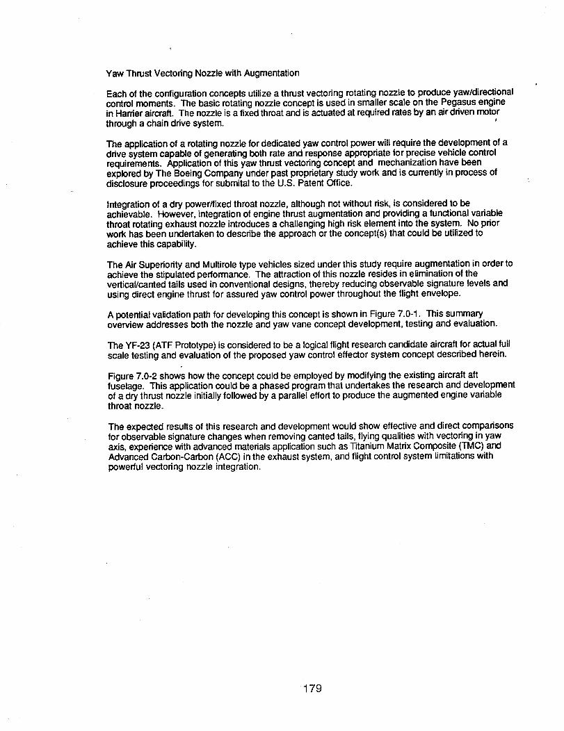
Yaw Thrust Vectoring Nozzle with Augmentation
Each of the configuration concepts utilize a thrust vectoring rotating nozzle to produce yaw/directionalcontrol moments. The basic rotating nozzle concept is used in smaller scale on the Pegasus enginein Harrier aircraft. The nozzle is a fixed throat and is actuated at required rates by an air driven motorthrough a chain drive system.
The applicationof a rotating nozzle for dedicated yaw control power will require the development of adrive system capable of generating both rate and response appropriate for precise vehicle controlrequirements. Application of this yaw thrust vectoring concept and mechanization have beenexplored by The Boeing Company under past proprietary study work and is currently in process ofdisclosure proceedings for submital to the U.S. Patent Office.
Integration of a dry power/fixed throat nozzle, although not without risk, is considered to beachievable. However, integration of engine thrust augmentation and providing a functional variablethroat rotating exhaust nozzle introducesa challenging high risk element into the system. No priorwork has been undertaken to describe the approach or the concept(s) that could be utilized toachieve this capability.
The Air Superiority and Multirole type vehicles sized under this study require augmentation in ordertoachieve the stipulated performance. The attractionof this nozzle resides in elimination of thevertical/canted tails used in conventional designs, thereby reducing observable signature levels andusing direct engine thrust for assured yaw control power throughout the flight envelope.
A potential validation path for developing this concept is shown in Figure 7.0-1. This summaryoverview addresses both the nozzle and yaw vane concept development, testing and evaluation.
The YF-23 (ATF Prototype) is considered to be a logicalflight research candidate aircraft for actual fullscale testing and evaluation of the proposed yaw control effector system concept described herein.
Figure 7.0-2 shows how the concept could be employed by modifyingthe existing aircraft aftfuselage. This application could be a phased program that undertakes the research and developmentof a drythrust nozzle initiallyfollowed by a parallel effort to produce the augmented engine variablethroat nozzle.
The expected results of this research and development would show effective and direct comparisonsfor observable signature changes when removing canted tails, flying qualities with vectoring in yawaxis, experience with advanced materials application such as Titanium Matrix Composite (TMC) andAdvanced Carbon-Carbon (ACC) in the exhaust system, and flight control system limitations withpowerful vectoring nozzle integration.
179

Flight Research Needs Assessment
Analysis methods weak
• Conceptual level Products of Inertia• Determining structual flutter boundaries• Non-linear aerodynamics• Engine transient response for bolters and acceleration performance
Control effectors - Continue quest for new ideas
• Wind Tunnel Database Development Quantify benefitsOptimal configurationsPenalties (blowing)
• Tiperons• All blowing and suctiondevices• Forebody strakes/chimes• Fluidic thrust vectoring
• Aerodynamics
EmpericalMethods
• Nonlinear aerodynamics *update DATCOM)• Use CFD to develop design methods (base drag)• Emperically corrected low order panel codes for conceptual design
CFD Methods
• Improve transition prediction• Continue validation of CFD methods• Improve turn-around and ease of use.
180
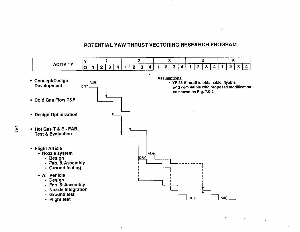
POTENTIAL YAW THRUST VECTORING RESEARCH PROGRAM
...I.
CO
ACTIVITYy 1 2 3 4 5
iQ 1121314 1121314 1121314 1121314 1121314
• Concept/DesignDevelopment
• Cold Gas Flow T&E
• Design Optimization
• Hot Gas T & E - FAB,Test & Evaluation
Flight Article- Nozzle system
- Design- Fab. & Assembly- Ground testing
- Air Vehicle
- Design- Fab. & Assembly- Nozzle Integration- Ground test
Flight test
Assumptions• YF-23 Aircraft is obtainable, flyable,
and compatible with proposed modificationas shown on Fig. 7.0-2
I DRY AUG.
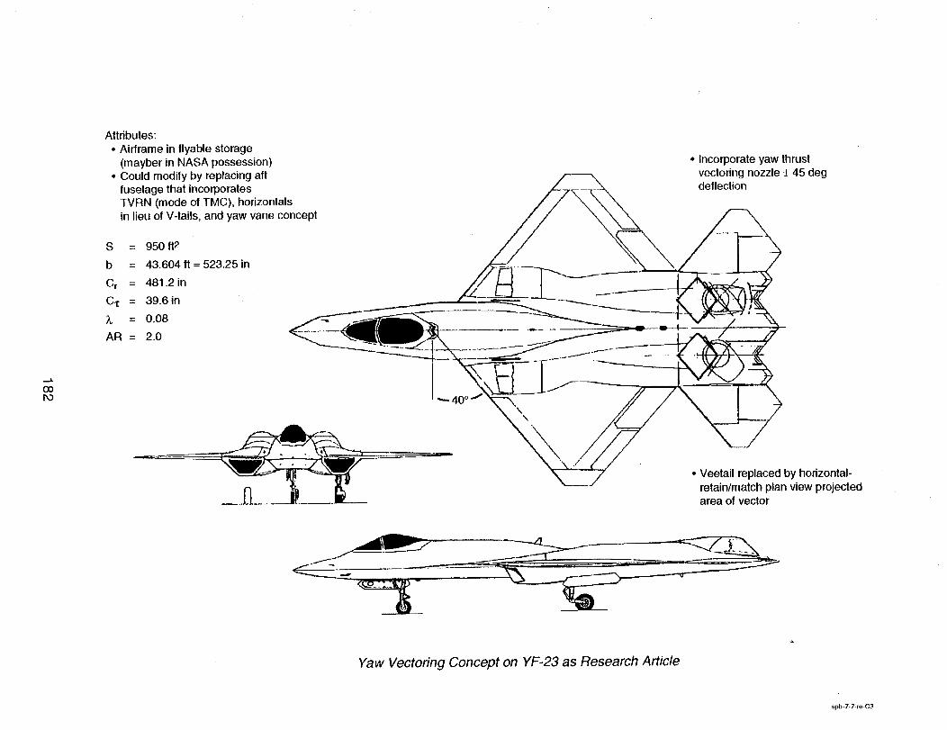
coPo
Attributes:
• Airframe in flyable storage(mayber in NASA possession)
• Could modify by replacing aftfuselage that incorporatesTVRN (mode of TMC), horizontals
in lieu of V-tails, and yaw vane concept
S = 950 It2
b = 43.604 It = 523.25 in
Cr = 481.2 in
C,_ = 39.6in
_t = 0.08
AR = 2.0
,,- 40 ° J\
\
• Incorporate yaw thrustvectonng nozzle _ 45 degdeflection
• Veetail replaced by horizontal-retain/match plan view projectedarea of vector
Yaw Vectoring Concept on YF-23 as Research Article
spb-7-7-re-C3
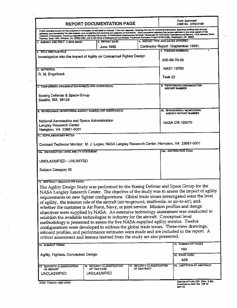
I Form ApprovedREPORT DOCUMENTATION PAGE OMBNo.0704-0188
Public reporting burden tol' lh L,,co41eOtion o_ kdo_lon Is HImI, ted to rage 1 ho_r per responme, irrciudhllg the tirrm lot revwng ir_ltruotwts, =eau,¢_tk_g e3dsUng data =_=t ¢er_
_tMrorlg dllfKJ_li_ the _ _ _ _ _ _i_ the _ _ It_o(Irqr_at_r_. SeN_d cofflmsntI re_rdillO th_ 19_t'Q_i¢_i_imlto or any other _ _ _i
oo_ection of ktlom_tto_, Including =u_lon= tot reducing this burden, to Wmh_tgton Headquarters Sen_=es, DIrecmr'ae for Irdom_t_n O_ and Reports, 1215 Jelter=_ Day _"
Highway, Sulto 1204, A._,_.._-_., VA _ and to the Office o_ I_ and Buciget, Paperwork Reductto_ Pro_ (0704-0t88), Wlh/_, DC 20r==03.
1. AGENCY USE ONLY (Leave blank) 2. REPORT DATE 3. REPORT TYPE AND DATES COVERED
June 1995 Contractor Report (September 1994)
4. TITLE AND SUBTITLE
InvestigationIntothe Impactof Agilityon ConceptualFighterDesign
i6. AUTHOR(S)
R. M. Engelbeck
7. PERFORMINGORGANIZATIONNAME(S)ANDADDRESS(ES)
Boeing Defense & Space GroupSeattle, WA 98124
9. SPONSORINGI MONITORINGAGENCYNAME(S)ANDADDRESS(ES)
National Aeronautics and Space Administration
Langley Research Center
Hampton, VA 23681-0001
5. FUNDING NUMBERS
505-68-70-09
NAS1-18762
Task 22
8. PERFORMING ORGANIZATIONREPORT NUMBER
:10. SPONSORING/MONITORINGAGENCY REPORT NUMBER
NASA CR-195079
I1. SUPPLEMENTARYNOTES
Contract Technical Monitor: M.J. Logan, NASA Langley Research Center, Hampton, VA 23681-0001
12a. DISTRIBUTIONI AVAILABILITYSTATEMENT
UNCLASSIFIED " UNLIMITED
Subject Category 05
12b. DISTRIBUTION CODE
13. ABSTRACT (Maximum 200 word_)
The Agility Design Study was performed by the Boeing Defense and Space Group for the
NASA Langley Research Center. The objective of the study was to assess the impact of agility
requirements on new fighter configurations. Global trade issues investigated were the level
of agility, the mission role of the aircraft (air-to-ground, multi-role, or air-to-air), and
whether the customer is Air Force, Navy, or joint service. Mission profiles and design
objectives were supplied by NASA. An extensive technology assessment was conducted to
establish the available technologies to industry for the aircraft. Conceptual level
methodology is presented to assess the five NASA-supplied agili,ty metrics. Twelve
configurations were developed to address the global trade issues. Three-view drawings,inboard profiles, and performance estimates were made and are included in the report. Acritical assessment and lessons learned from the study are also presented.
14.SUBJECTTERMS
Agility,Fighters,ConceptualDesign
:17. SECURITY CLASSIFICATIONOF REPORT
UNCLASSIFIED
NSN 7540-01-280-5500
18. SECURITY CLASSIFICATION
OF THIS PAGE
UNCLASSIFIED
19. SECURITY CLASSIFICATIONOF ABSTRACT
15. NUMBER OF PAGES
190
16. PRICE CODE
A0920. LIMITATION OF ABSTRACT
Standard Form 298 (Rev. 2-89)prescribed by ANSI StcL Z3_18
298-102