Embed Size (px)
Citation preview
Investigating the maximum soil pressure on aconcrete pipe with poor haunch support subjectedto traffic live load using numerical modellingChapman, David; Alzabeebee, Saif; Jefferson, Ian; Faramarzi, Asaad
License:None: All rights reserved
Document VersionPeer reviewed version
Citation for published version (Harvard):Chapman, D, Alzabeebee, S, Jefferson, I & Faramarzi, A 2016, 'Investigating the maximum soil pressure on aconcrete pipe with poor haunch support subjected to traffic live load using numerical modelling' Paper presentedat 11th Pipeline Technology Conference, Berlin, Germany, 23/05/16 - 25/05/16, .
Link to publication on Research at Birmingham portal
General rightsUnless a licence is specified above, all rights (including copyright and moral rights) in this document are retained by the authors and/or thecopyright holders. The express permission of the copyright holder must be obtained for any use of this material other than for purposespermitted by law.
•Users may freely distribute the URL that is used to identify this publication.•Users may download and/or print one copy of the publication from the University of Birmingham research portal for the purpose of privatestudy or non-commercial research.•User may use extracts from the document in line with the concept of ‘fair dealing’ under the Copyright, Designs and Patents Act 1988 (?)•Users may not further distribute the material nor use it for the purposes of commercial gain.
Where a licence is displayed above, please note the terms and conditions of the licence govern your use of this document.
When citing, please reference the published version.
Take down policyWhile the University of Birmingham exercises care and attention in making items available there are rare occasions when an item has beenuploaded in error or has been deemed to be commercially or otherwise sensitive.
If you believe that this is the case for this document, please contact [email protected] providing details and we will remove access tothe work immediately and investigate.
Download date: 14. Jul. 2018
Pipeline Technology Conference 2016
1
Investigating the maximum soil pressure on a concrete pipe with poor haunch support subjected to traffic live load using numerical modelling
Saif Alzabeebee, David N Chapman, Ian Jefferson, and Asaad Faramarzi
School of Engineering, University of Birmingham, Birmingham, United Kingdom
Abstract The behaviour of rigid pipes during backfilling, under soil weight, and under traffic live loads has received considerable attention from researchers in the past. A significant number of numerical, laboratory, and full scale studies on the response of rigid pipes under these effects have been published, which provide clear guidelines for the likely behaviour of the pipe. However, these studies were conducted assuming full support for the pipe in the haunch zone, although proper haunch support is, in fact, difficult to achieve in practice. This study therefore focuses on the effect of poor haunch support on the maximum soil pressure developed on a buried concrete pipe under traffic live loading using three-dimensional finite element modelling. The Duncan-Chang hyperbolic soil model has been used to represent the soil material and the pipe behaviour is simulated with a linear elastic model. The live load considered in the analyses is based on the British Standard design requirement (two axles with a maximum axle load of 450 kN). The poor haunch support has been modelled by removing the soil elements in the haunch zone to simulate the worst case scenario. The results show that the effect of poor haunch support causes significant increases in the maximum soil pressure and has considerable implications for the design of rigid pipes.
1. Introduction Ensuring good compaction of the soil in the haunch zone is very important for providing a buried pipe with enough support and uniformly distributing the load around the pipe during its service life. A significant number of numerical, laboratory, and full scale studies on the response of rigid and flexible pipes have been published, which provide clear guidelines for the likely behaviour of the pipes (Rogers, 1999, Yoo et al., 1999, Dhar et al., 2004, Sargand et al., 2005, Arockiasamy et al., 2006, Wong et al., 2006, Trickey and Moore, 2007, Elshimi and Moore, 2013, Kang et al., 2013a, Kang et al., 2013b, Bryden et al., 2014, and Kraus et al., 2014). However, the previous studies were conducted assuming full support for the pipe in the haunch zone, although proper haunch support is, in fact, difficult to achieve in practice (Boschert and Howard, 2014). Despite the importance of this topic in the practical application of rigid pipeline design, little attention has been paid to it in the literature where the majority of the previous studies have focused on the behaviour of the pipes due to loss of support as a result of pipe leakage (i.e. void formation). Dhar et al. (2004) used a validated two-dimensional finite element model to study the effect of poor haunch support on the structural response of ribbed polyvinyl chloride (PVC) and corrugated high density polyethylene (HDPE) pipes under soil overburden pressure. The inner diameter of the PVC and HDPE pipes was 60.5 cm and 61 cm, respectively. They found that poor haunch support increased the vertical displacement of the pipe. They further found that poor haunch support also caused a
Pipeline Technology Conference 2016
2
redistribution of strains around the circumference of the pipe, with the strains being concentrated at the haunch for both the HDPE and PVC pipes. Balkaya et al. (2012) studied the effect of voiding due to pipe leakage on the behaviour of cast iron (CI) pipes with a 2.5 m overburden pressure using three dimensional finite element modelling. Voids were introduced in the bedding and the haunch zone. The effect of void depth, void length, and void angle were investigated. Medium-dense and dense sandy soils were considered in the analysis. An internal water pressure of 400 kPa was also considered in the analysis. It was found that increasing the void size increased the stresses generated in the pipe and resulted in a decrease in the factor of safety against tensile rupture. Balkaya et al. (2013) repeated the same investigation on a PVC water pipe, where the outer diameter of the pipe was 15 cm and the wall thickness was 0.5 cm. The internal water pressure was again assumed to be 400 kPa. The behaviour was studied under the effect a 2.5 m overburden soil pressure. Comparing the results of the uniform bedding and the bedding with a void showed that the presence of a void increased the tensile stress in the pipe wall. The percentage increase of the maximum tensile stress ranged from 37% to 69% for the medium sand and 45% to 95% for the dense sand. Kamel and Meguid (2013) studied experimentally and numerically the effect of voids due to erosion on the soil pressure distribution around a buried steel pipe with an outer diameter of 15 cm and wall thickness of 2.5 cm. The backfill height to diameter ratio was equal to 2. In these tests, the contact loss (retractable strip) was placed at the invert, haunch, and springline. The experimental results showed that the contact loss at the springline and haunch increases the earth pressure by 30% from its initial value. Meguid and Kamel (2014) used a three dimensional finite element program ABAQUS to study the effect of an erosion void on the response of a buried concrete pipe with an inner diameter of 60 cm, wall thickness of 7 cm, and a soil cover height of 3 m. The results showed that the presence of the erosion void increased the earth pressure compared with the case of no erosion void. The increase in earth pressure was more than 100 % for the case of a void located at the spring line and approximately 30% for the case of a void located at the invert.
From this brief review, it can be seen that the previous studies assumed a void with limited dimensions, they also did not consider the loss of support in the full haunch area, as well as not considering the effect of traffic live load. The present study therefore focuses on studying the effect of the poor soil support in the full haunch zone for a concrete pipe under an overburden pressure and the British Standard traffic live load (BS 9295, 2010). The aim was to study the impact of poor haunch support on the maximum soil pressure on a concrete pipe and how this might affect design practice.
2. Numerical modelling details Concrete pipes with diameters ranging from 41 cm to 289 cm (Peterson et al. 2010) were modelled as part of this study. However, the results for one representative pipe are presented in the paper to illustrate the key findings. The concrete pipe had a diameter of 76 cm and a wall thickness of 7.62 cm and was modelled using the finite element package MIDAS GTS NX 2015. The length, width, and height of the numerical model were equal to 15 m, 12 m, and 10 m, respectively and were chosen based on a sensitivity analysis to avoid any boundary effect. Four noded tetrahedron solid elements were used to model the surrounding soil and the trench, while three noded triangular shell elements were used to model the pipe. The average element
Pipeline Technology Conference 2016
3
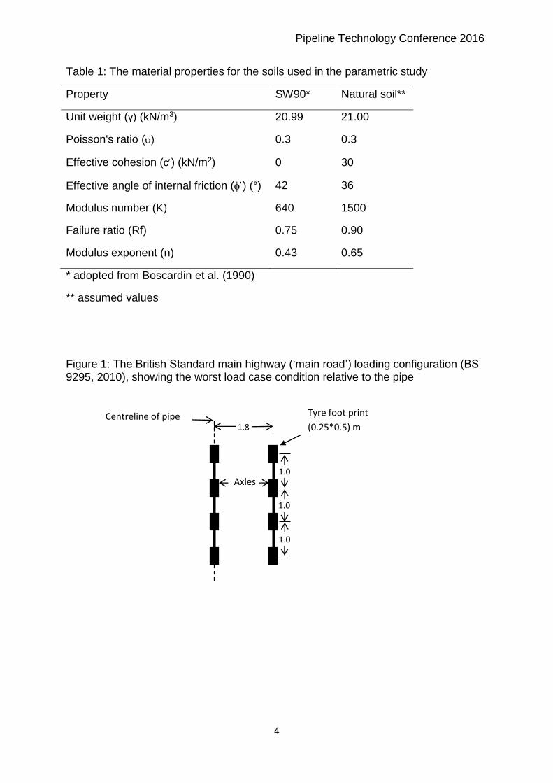
size was 0.15 m for the pipe, 0.15 m for the trench, 0.25 for the bedding layer, and 0.5 m for the surrounding soil. The bedding layer was assumed to have a thickness of 10 cm. The British Standard main highway (‘main road’) traffic load has been considered because this loading configuration simulates the worst case scenario (BS 9295, 2010). This loading configuration comprises two axles with four wheels in each axle as shown in Figure 1. The total single wheel load is equal to 112.5 kN. The wheel load area is assumed to have a length of 0.5 m and a width of 0.25 m (Petersen et al., 2010 and Kang et al., 2013a). To find the critical loading condition of the traffic live load, the effect of truck position for the cases of a truck travelling parallel and transverse to the pipeline direction was investigated. It was found that the maximum stresses and deformations in the pipe occur when the truck is moving transverse to the pipe direction with the first axle being directly above the pipe. The hyperbolic Duncan-Chang soil model (Duncan and Chang, 1970) was used to model the in situ soil, bedding soil, and backfill soil. A linear elastic model was used to model the pipe. A well-graded sand with a degree of compaction of 90% (SW90) was considered for both the backfill and bedding soils. The unit weight material properties of the compacted soil and the pipe have been adopted from the literature (Boscardin et al., 1990, and Petersen et al., 2010), while the in situ soil was assumed to be stronger than the backfill soil. All of the material properties of the bedding soil, backfill soil, and surrounding soil are shown in Table 1. The modulus of elasticity (E) and the
Poisson ratio () of the pipe were taken equal to 24856 MPa and 0.2, respectively (Petersen et al., 2010). The backfill heights ranged from 1.0 m to 4.5 m. The finite element mesh used in these analyses is shown in Figure 2a. Four steps were performed in the finite element analyses.
Step 1: The initial earth pressures for the in situ soil were calculated. A coefficient of lateral earth pressure of 1 was assumed for the in situ soil.
Step2: The trench was excavated.
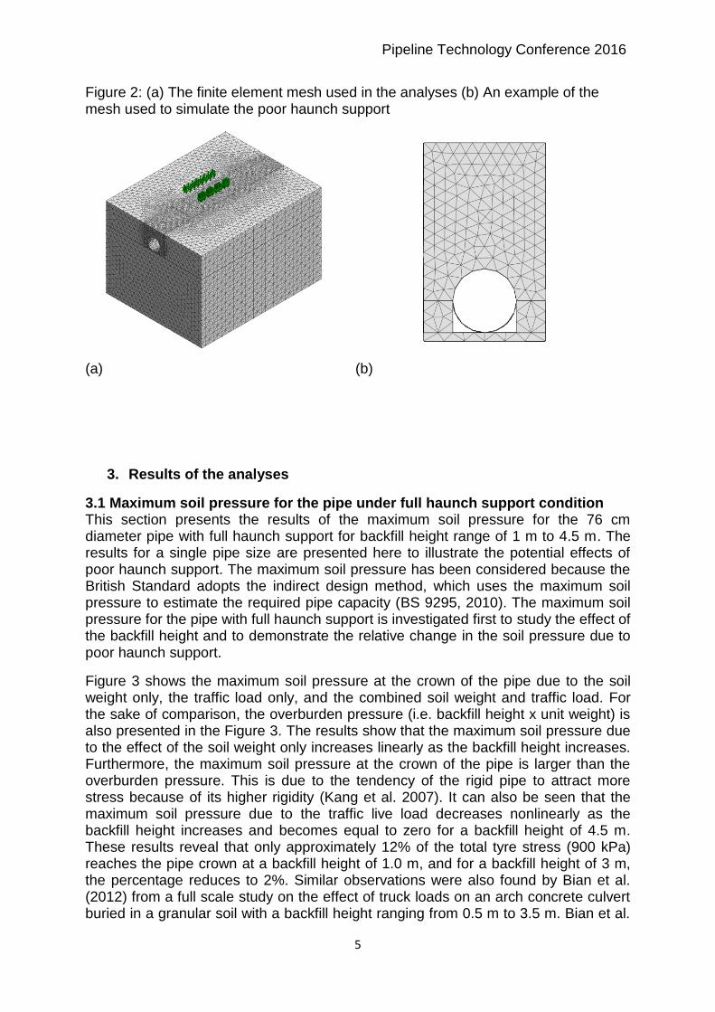
Step 3: The bedding soil, pipe, and backfill soil were added. The lateral earth pressure coefficient for the compacted soil was assumed to be 1 (Brown and Selig, 1990). To simulate the poor haunch support, the soil elements in the haunch zone were not added in the model so there was a void along the whole pipe length in the haunch zone as shown in Figure 2b.
Step 4: The traffic live load was applied with a total number of 25 equal steps.
Pipeline Technology Conference 2016
4
Table 1: The material properties for the soils used in the parametric study
Property SW90* Natural soil**
Unit weight (γ) (kN/m3) 20.99 21.00
Poisson's ratio () 0.3 0.3
Effective cohesion (c) (kN/m2) 0 30
Effective angle of internal friction () (°) 42 36
Modulus number (K) 640 1500
Failure ratio (Rf) 0.75 0.90
Modulus exponent (n) 0.43 0.65
* adopted from Boscardin et al. (1990)
** assumed values
Figure 1: The British Standard main highway (‘main road’) loading configuration (BS 9295, 2010), showing the worst load case condition relative to the pipe
Centreline of pipe Tyre foot print
(0.25*0.5) m 1.8
1.0
1.0
1.0
Axles
Pipeline Technology Conference 2016
5
Figure 2: (a) The finite element mesh used in the analyses (b) An example of the mesh used to simulate the poor haunch support
(a)
(b)
3. Results of the analyses
3.1 Maximum soil pressure for the pipe under full haunch support condition This section presents the results of the maximum soil pressure for the 76 cm diameter pipe with full haunch support for backfill height range of 1 m to 4.5 m. The results for a single pipe size are presented here to illustrate the potential effects of poor haunch support. The maximum soil pressure has been considered because the British Standard adopts the indirect design method, which uses the maximum soil pressure to estimate the required pipe capacity (BS 9295, 2010). The maximum soil pressure for the pipe with full haunch support is investigated first to study the effect of the backfill height and to demonstrate the relative change in the soil pressure due to poor haunch support.
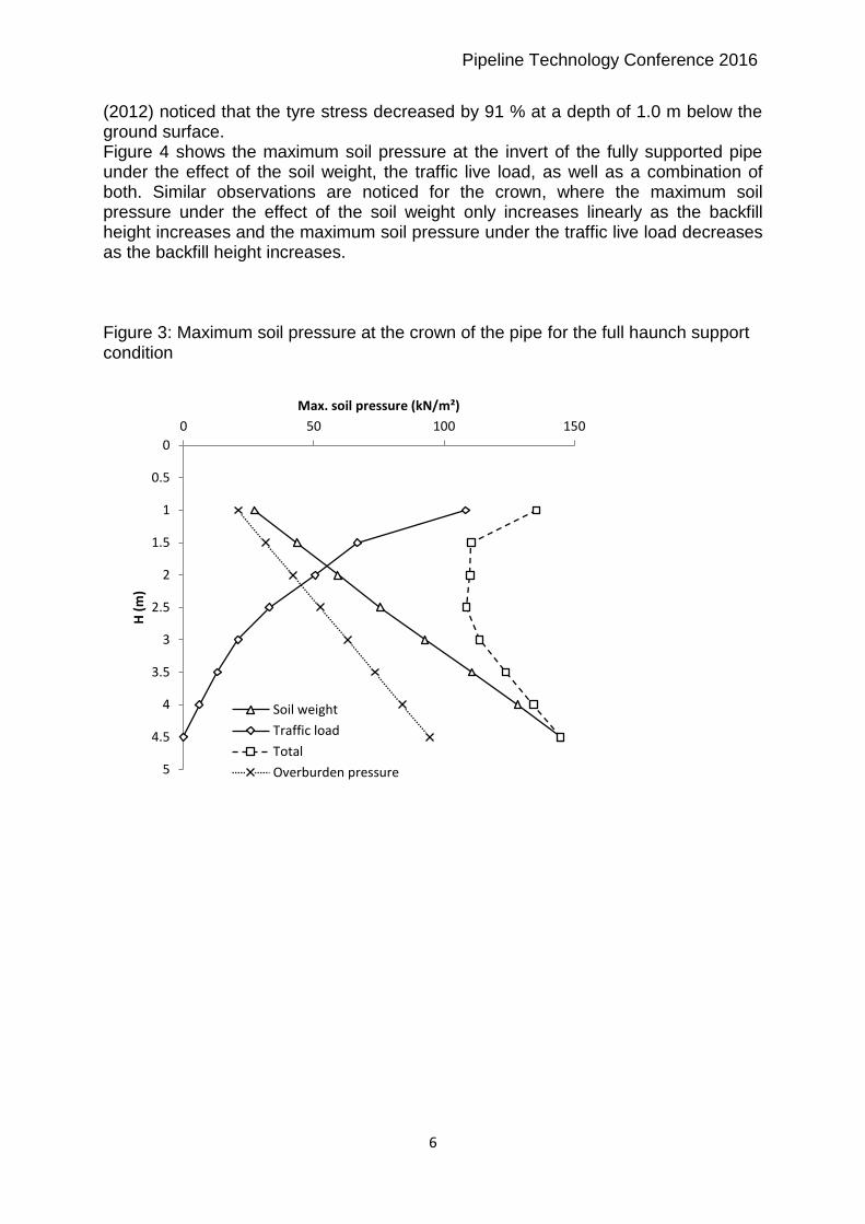
Figure 3 shows the maximum soil pressure at the crown of the pipe due to the soil weight only, the traffic load only, and the combined soil weight and traffic load. For the sake of comparison, the overburden pressure (i.e. backfill height x unit weight) is also presented in the Figure 3. The results show that the maximum soil pressure due to the effect of the soil weight only increases linearly as the backfill height increases. Furthermore, the maximum soil pressure at the crown of the pipe is larger than the overburden pressure. This is due to the tendency of the rigid pipe to attract more stress because of its higher rigidity (Kang et al. 2007). It can also be seen that the maximum soil pressure due to the traffic live load decreases nonlinearly as the backfill height increases and becomes equal to zero for a backfill height of 4.5 m. These results reveal that only approximately 12% of the total tyre stress (900 kPa) reaches the pipe crown at a backfill height of 1.0 m, and for a backfill height of 3 m, the percentage reduces to 2%. Similar observations were also found by Bian et al. (2012) from a full scale study on the effect of truck loads on an arch concrete culvert buried in a granular soil with a backfill height ranging from 0.5 m to 3.5 m. Bian et al.
Pipeline Technology Conference 2016
6
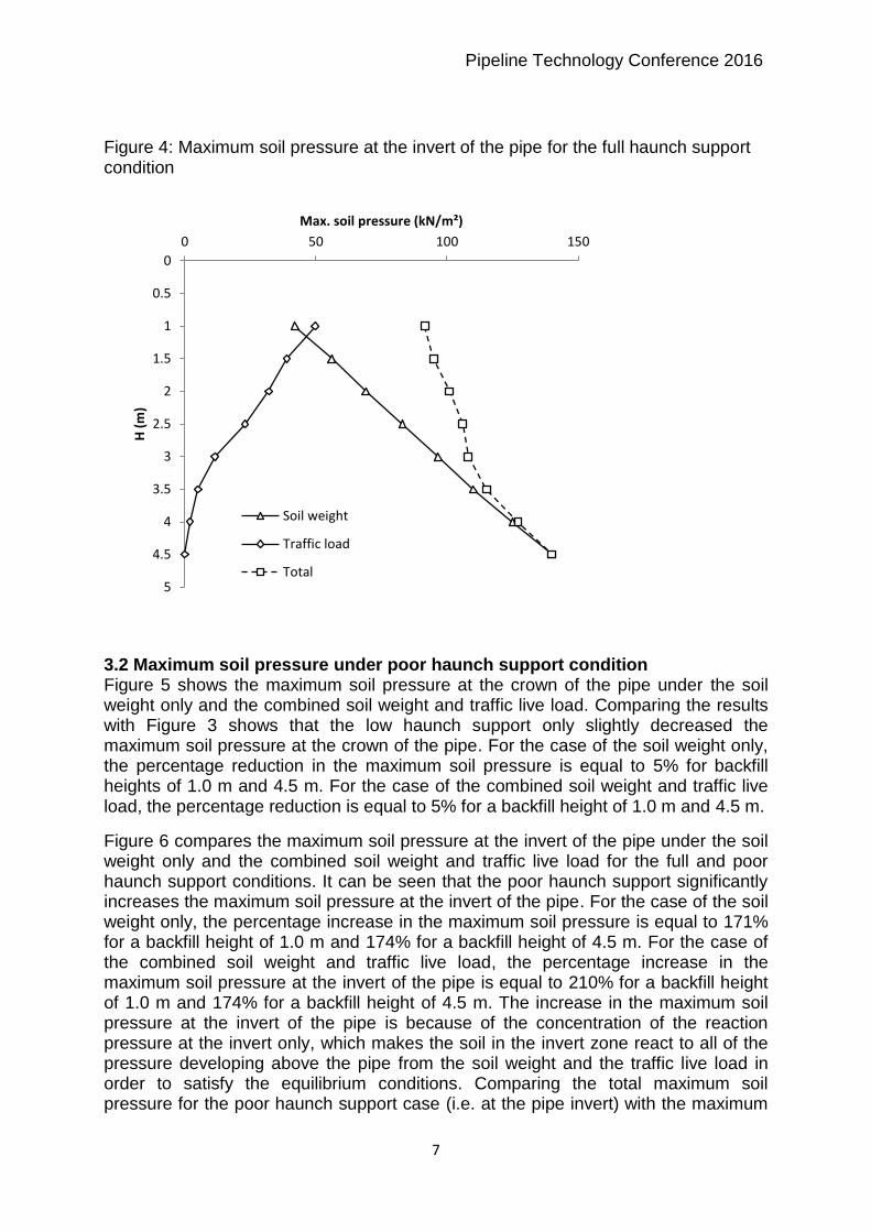
(2012) noticed that the tyre stress decreased by 91 % at a depth of 1.0 m below the ground surface. Figure 4 shows the maximum soil pressure at the invert of the fully supported pipe under the effect of the soil weight, the traffic live load, as well as a combination of both. Similar observations are noticed for the crown, where the maximum soil pressure under the effect of the soil weight only increases linearly as the backfill height increases and the maximum soil pressure under the traffic live load decreases as the backfill height increases. Figure 3: Maximum soil pressure at the crown of the pipe for the full haunch support condition
0
0.5
1
1.5
2
2.5
3
3.5
4
4.5
5
0 50 100 150
H (
m)
Max. soil pressure (kN/m²)
Soil weight
Traffic load
Total
Overburden pressure
Pipeline Technology Conference 2016
7
Figure 4: Maximum soil pressure at the invert of the pipe for the full haunch support condition
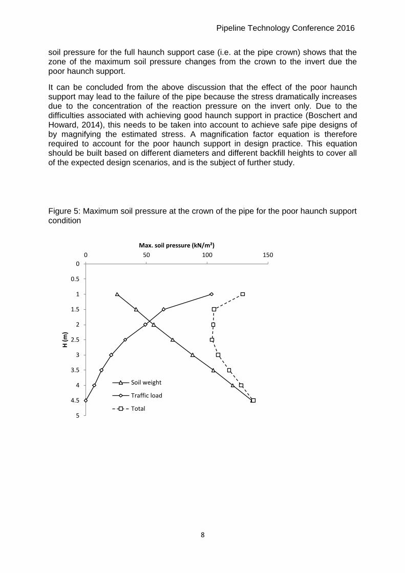
3.2 Maximum soil pressure under poor haunch support condition Figure 5 shows the maximum soil pressure at the crown of the pipe under the soil weight only and the combined soil weight and traffic live load. Comparing the results with Figure 3 shows that the low haunch support only slightly decreased the maximum soil pressure at the crown of the pipe. For the case of the soil weight only, the percentage reduction in the maximum soil pressure is equal to 5% for backfill heights of 1.0 m and 4.5 m. For the case of the combined soil weight and traffic live load, the percentage reduction is equal to 5% for a backfill height of 1.0 m and 4.5 m.
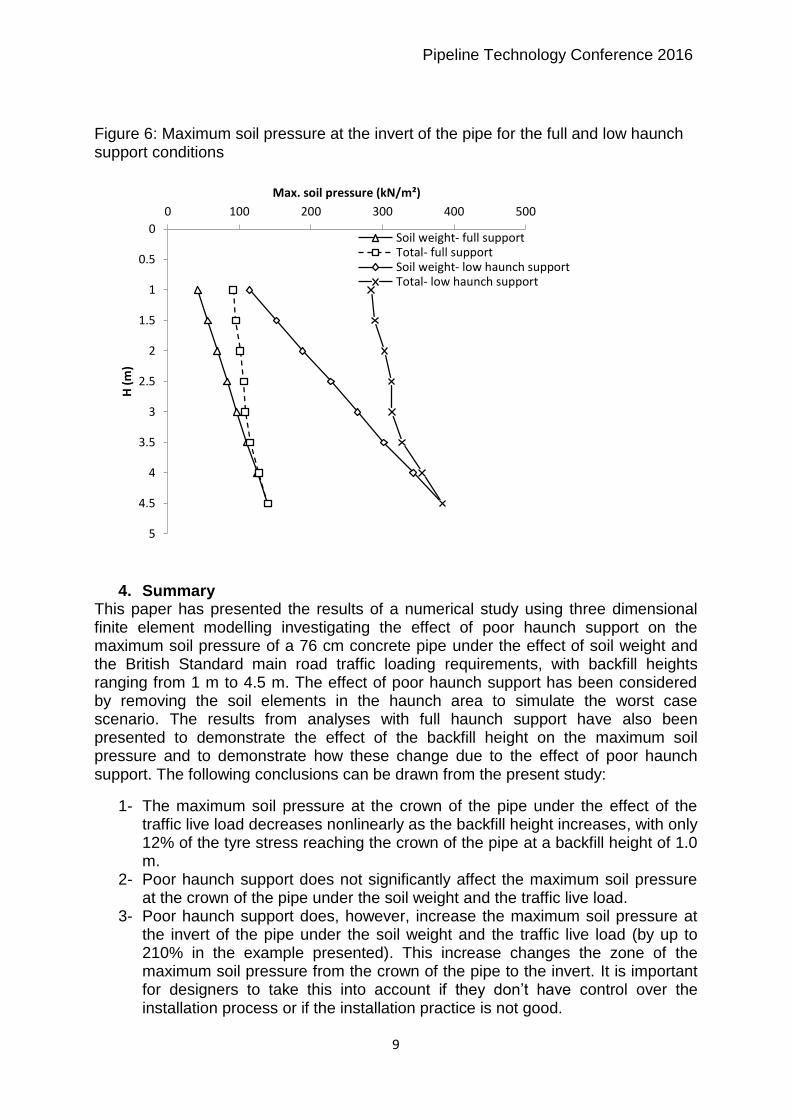
Figure 6 compares the maximum soil pressure at the invert of the pipe under the soil weight only and the combined soil weight and traffic live load for the full and poor haunch support conditions. It can be seen that the poor haunch support significantly increases the maximum soil pressure at the invert of the pipe. For the case of the soil weight only, the percentage increase in the maximum soil pressure is equal to 171% for a backfill height of 1.0 m and 174% for a backfill height of 4.5 m. For the case of the combined soil weight and traffic live load, the percentage increase in the maximum soil pressure at the invert of the pipe is equal to 210% for a backfill height of 1.0 m and 174% for a backfill height of 4.5 m. The increase in the maximum soil pressure at the invert of the pipe is because of the concentration of the reaction pressure at the invert only, which makes the soil in the invert zone react to all of the pressure developing above the pipe from the soil weight and the traffic live load in order to satisfy the equilibrium conditions. Comparing the total maximum soil pressure for the poor haunch support case (i.e. at the pipe invert) with the maximum
0
0.5
1
1.5
2
2.5
3
3.5
4
4.5
5
0 50 100 150
H (
m)
Max. soil pressure (kN/m²)
Soil weight
Traffic load
Total
Pipeline Technology Conference 2016
8
soil pressure for the full haunch support case (i.e. at the pipe crown) shows that the zone of the maximum soil pressure changes from the crown to the invert due the poor haunch support.
It can be concluded from the above discussion that the effect of the poor haunch support may lead to the failure of the pipe because the stress dramatically increases due to the concentration of the reaction pressure on the invert only. Due to the difficulties associated with achieving good haunch support in practice (Boschert and Howard, 2014), this needs to be taken into account to achieve safe pipe designs of by magnifying the estimated stress. A magnification factor equation is therefore required to account for the poor haunch support in design practice. This equation should be built based on different diameters and different backfill heights to cover all of the expected design scenarios, and is the subject of further study.
Figure 5: Maximum soil pressure at the crown of the pipe for the poor haunch support condition
0
0.5
1
1.5
2
2.5
3
3.5
4
4.5
5
0 50 100 150
H (
m)
Max. soil pressure (kN/m²)
Soil weight
Traffic load
Total
Pipeline Technology Conference 2016
9
Figure 6: Maximum soil pressure at the invert of the pipe for the full and low haunch support conditions
4. Summary This paper has presented the results of a numerical study using three dimensional finite element modelling investigating the effect of poor haunch support on the maximum soil pressure of a 76 cm concrete pipe under the effect of soil weight and the British Standard main road traffic loading requirements, with backfill heights ranging from 1 m to 4.5 m. The effect of poor haunch support has been considered by removing the soil elements in the haunch area to simulate the worst case scenario. The results from analyses with full haunch support have also been presented to demonstrate the effect of the backfill height on the maximum soil pressure and to demonstrate how these change due to the effect of poor haunch support. The following conclusions can be drawn from the present study:
1- The maximum soil pressure at the crown of the pipe under the effect of the traffic live load decreases nonlinearly as the backfill height increases, with only 12% of the tyre stress reaching the crown of the pipe at a backfill height of 1.0 m.
2- Poor haunch support does not significantly affect the maximum soil pressure at the crown of the pipe under the soil weight and the traffic live load.
3- Poor haunch support does, however, increase the maximum soil pressure at the invert of the pipe under the soil weight and the traffic live load (by up to 210% in the example presented). This increase changes the zone of the maximum soil pressure from the crown of the pipe to the invert. It is important for designers to take this into account if they don’t have control over the installation process or if the installation practice is not good.
0
0.5
1
1.5
2
2.5
3
3.5
4
4.5
5
0 100 200 300 400 500
H (
m)
Max. soil pressure (kN/m²)
Soil weight- full supportTotal- full supportSoil weight- low haunch supportTotal- low haunch support
Pipeline Technology Conference 2016
10
Acknowledgement
The authors would like to acknowledge the financial support for this research
provided by the Higher Committee for Education Development in Iraq (HCED).
References Arockiasamy M, Chaallal O and Limpeteeprakarn T (2006) Full-scale field tests on
flexible pipes under live load application. Journal of Performance of Constructed Facilities 20(1): 21–27.
Balkaya M, Moore I and Sağlamer A (2012) Study of nonuniform bedding support because of erosion under cast iron water distribution pipes. Journal of Geotechnical and Geoenvironmental Engineering 138(10): 1247–1256.
Balkaya M, Moore ID and Sağlamer A (2013) Study of non-uniform bedding support under continuous PVC water distribution pipes. Tunnelling and Underground Space Technology 35: 99–108.
Bian X, Tang X, Shen W et al. (2012) An experimental study on a culvert buried in granular soil subjected to vehicle loads. Advances in Structural Engineering 15(6): 1031–1040.
Boscardin MD, Selig ET, Lin RS and Yang GR (1990) Hyperbolic parameter for compacted soils. Journal of Geotechnical Engineering ASCE 116(1): 88–104.
Boschert J and Howard A (2014) Importance of haunching. Pipelines 2014: From Underground to the Forefront of Innovation and Sustainability. ASCE, Portland, Oregon, USA, pp. 393-404.
Brown SF and Selig ET (1991). The design of pavement and rail track foundations. In: O’Reilly MP and Brown SF. Cyclic loading of soils: from theory to practice. Glasgow and London: Blackie and Son Ltd, pp. 249-305.
Bryden P, El Naggar H and Valsangkar A (2014) Soil-structure interaction of very flexible pipes: centrifuge and numerical investigations. International Journal of Geomechanics, 10.1061/(ASCE)GM.1943-5622.0000442, 04014091.
BS 9295 (2010). Guide to the structural design of buried pipelines. BSI, London, UK. Dhar AS, Moore ID and McGrath TJ (2004) Two-dimensional analyses of
thermoplastic culvert displacements and strains. Journal of Geotechnical and Geoenvironmental Engineering 130(2): 199–208.
Duncan JM and Chang C (1970). Nonlinear analysis of stress and strain in soils. Journal of the Soil Mechanics and Foundations Division ASCE 96(5): 1629–1653.
Elshimi TM and Moore ID (2013) Modeling the effects of backfilling and soil compaction beside shallow buried pipes. Journal of Pipeline Systems Engineering and Practice ASCE, 10.1061/(ASCE)PS.1949-1204.0000136, 04013004.
Kamel S and Meguid MA (2013) Investigating the effects of local contact loss on the earth pressure distribution on rigid pipes. Geotechnical and Geological Engineering 31(1): 199–212.
Kang J, Jung Y and Ahn Y (2013a) Cover requirements of thermoplastic pipes used under highways. Composites Part B-Engineering 55: 184–192.
Kang J, Parker F and Yoo CH (2007) Soil-structure interaction and imperfect trench installation for deeply buried concrete pipes. Journal of Geotechnical and Geoenvironmental Engineering 133(3): 277–285.
Kang JS, Stuart SJ and Davidson JS (2013b) Analytical evaluation of maximum cover limits for thermoplastic pipes used in highway construction. Structure and Infrastructure Engineering 9(7): 667–674.
Pipeline Technology Conference 2016
11
Kraus E, Oh J and Fernando EG (2014) Impact of repeat overweight truck traffic on buried utility facilities. Journal of Performance of Constructed Facilities, 10.1061/(ASCE)CF.1943-5509.0000454, 04014004.
Meguid MA and Kamel S (2014) A three-dimensional analysis of the effects of erosion voids on rigid pipes. Tunnelling and Underground Space Technology 43: 276–289.
Petersen Dl, Nelson CR, McGrath TJ and Kitane Y (2010) Recommended design specifications for live load distribution to buried structures. Transport Research Board, Washington, USA.
Rogers CDF (1999) The structural performance of flexible pipe for landfill drainage. Proceedings of the Institution of Civil Engineers- Geotechnical Engineering 137(4): 249–260, 10.1680/gt.1999.370410.
Sargand SM, Masada T, Tarawneh B and Gruver D (2005) Field performance and analysis of large-diameter high-density polyethylene pipe under deep soil fill. Journal of Geotechnical and Geoenvironmental Engineering 131(1): 39–51.
Trickey SA and Moore ID (2007) Three-dimensional response of buried pipes under circular surface loading. Journal of Geotechnical and Geoenvironmental Engineering 133(2): 219–223.
Wong LS, Allouche EN, Dhar AS et al. (2006) Long-term monitoring of SIDD type IV installations. Canadian Geotechnical Journal 43(4): 392–408.
Yoo CS, Lee KM, Chung SW and Kim JS (1999) Interaction between flexile buried pipe and surface load. Journal of Korean Geotechnical Society 15(3): 83–97.