Embed Size (px)
Citation preview

R&D, FEA, CFD, Material Selection, Testing & Assessment © Continuum Blue Ltd
Research & Development, FEA, CFD,
Material Selection, Testing & Assessment
Presenter: Mark Yeoman PhD
Date: 19 October 2017
M S Yeoman PhD1 1. Continuum Blue Limited, One Caspian Point, Caspian Way, CF10 4DQ, United Kingdom
Investigating the loading behaviour of intact &
meniscectomy knee joints & the impact on
surgical decisions

© Continuum Blue Ltd www.continuum-blue.com
MENISCI LATERAL & MEDIAL
Lateral side Medial side
The meniscus is a crescent-shaped fibrocartilaginous structure that lies between the cartilage of the femur and tibia of the knee joint. Two menisci are present in each knee joint, one medial and one lateral, together they cushion & stabilize the knee[1].

© Continuum Blue Ltd www.continuum-blue.com
The Problem

© Continuum Blue Ltd www.continuum-blue.com
MENISCI TEARS & REPAIR HEALING VS. NON-HEALING
Medial meniscus
Displaced radial tear
Longitudinal Horizontal Radial Flap tear
Peripheral (outer rim) tears are highly vascularized and thus have the potential to heal. Inner rim tears which lack a good blood supply do not tend to heal.
Generally not repairable. Repairable, depending on their location,

© Continuum Blue Ltd www.continuum-blue.com
Multiphysics
Model

© Continuum Blue Ltd www.continuum-blue.com
MRI DATA 44 YEAR OLD CAUCASIAN MALE
• MRI imaging data was obtained from a 48 year old Caucasian male (weight 78kgs), with no previous history of hip, knee or ankle problems.
• 3D Slicer v4.6 [2-3] software was used to segment the MRI data

© Continuum Blue Ltd www.continuum-blue.com
GEOMETRIES INCLUDED IN MODEL KNEE DOMAINS
Femur
Medial Meniscus
Lateral Meniscus
Patella & Cartilage
Anterior Cruciate
Ligament (ACL)
Posterior Cruciate
Ligament (PCL)
Medial Collateral
Ligament (MCL)
Lateral Collateral
Ligament (LCL) Tibia Cartilage
Femur Cartilage
Medial Condyle
Lateral Condyle
Patellar Ligament
(PL)
Quadriceps Femoris
Tendon (QFT)
Tibia Fibula

© Continuum Blue Ltd www.continuum-blue.com
VIRTUAL SURGERIES VS. INTACT RESECTION LENGTHS & POSITION
Model 1: Natural Intact (no-defect)
Model 2: Partial Meniscectomy 1
(30mm resection)
Model 3: Partial Meniscectomy 2
(35mm resection)
Lateral side
Medial side

© Continuum Blue Ltd www.continuum-blue.com
LOAD & BOUNDARY CONDITIONS STANDING & GAIT CYCLE
load and boundary conditions applied to the knee model included two load cases,
namely:
1. Standing
2. Walking gait
The standing load case assumed zero rotations or moments applied to the femur bony
components, and only an axial load is applied from the inferior surfaces of the tibia
and fibula. Axial load is equal to half the axial force of the weight of the patient.
The walking gait load case assesses the knee model during a gait cycle (stance and
swing).

© Continuum Blue Ltd www.continuum-blue.com
GAIT CYCLE BOUNDARY CONTITIONS GAIT CYCLE ROTATIONS
Rotations, including flexion-extension, internal-
external and abduction-adduction were applied
to the femur, while the tibia is axially loaded in
compression and allowed to freely traverse
laterally and in the posterior-anterior direction
without rotation.
The applied rotations were based on the mean
rotations in the three planes (sagittal, coronal
and axial) obtained from [16].

© Continuum Blue Ltd www.continuum-blue.com
KNEE COMPRESSIVE LOAD DURING GAIT REFERENCED FROM TIBIA
% Gait Cycle
Knee
Co
mp
ress
ive
Forc
e p
er U
nit
Wei
ght
(N/k
g)
Distal compressive loads were applied on the tibia and fibula inferior surfaces.
Compressive loads are based on the stance phase of the control group from Sanford et al.
(2014)[14], which are reported in the reference frame of the segment distal (or tibia) to the knee
joint.
The average weight of the control group was 65.5 kg[14]. This was used to normalise the
compressive force curves & adjust them to the weight of our specific patient weight (78kg).
The stride compressive force curves from [14]
Normalised gait cycle compressive force
per unit mass curve utilised in the model

© Continuum Blue Ltd www.continuum-blue.com
MATERIAL RELATIONS MODEL
Knee bodies Material Model Density (g/cm3)
Modulus (MPa)
Poisson’s Ratio
Reference
Deformable Bony Components
(Femur, Tibia, Fibula & Patella)
Linear elastic (isotropic)
2 15x103 0.3 [7]
Articular cartilage Linear elastic
(isotropic) 1 15 0.475 [10]
Menisci Linear elastic (orthotropic)
1.5
E1: 20 12: 0.3
[10] E2: 120 13: 0.45
E3: 20 23: 0.3
Ligaments Hyper-elastic
(neo-Hookean) 1
LCL: 6.06 0.45
[11]
MCL: 6.43 0.45
ACL: 5.83 0.45
PCL: 6.06 0.45
PL: 5.83 0.45
QFT: 5.83 0.45
Direction 1 is radial, 2 is circumferential, and 3 is axial
Refer to Figure 2 for acronyms for specific ligaments

© Continuum Blue Ltd www.continuum-blue.com
CONTACT SETS FRICTIONLESS
Contact set between all articulating surfaces, including between ligaments & cartilage
© Continuum Blue Ltd www.continuum-blue.com
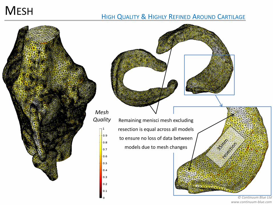
MESH HIGH QUALITY & HIGHLY REFINED AROUND CARTILAGE
Mesh Quality Remaining menisci mesh excluding
resection is equal across all models
to ensure no loss of data between
models due to mesh changes

© Continuum Blue Ltd www.continuum-blue.com
Analysis Results

© Continuum Blue Ltd www.continuum-blue.com
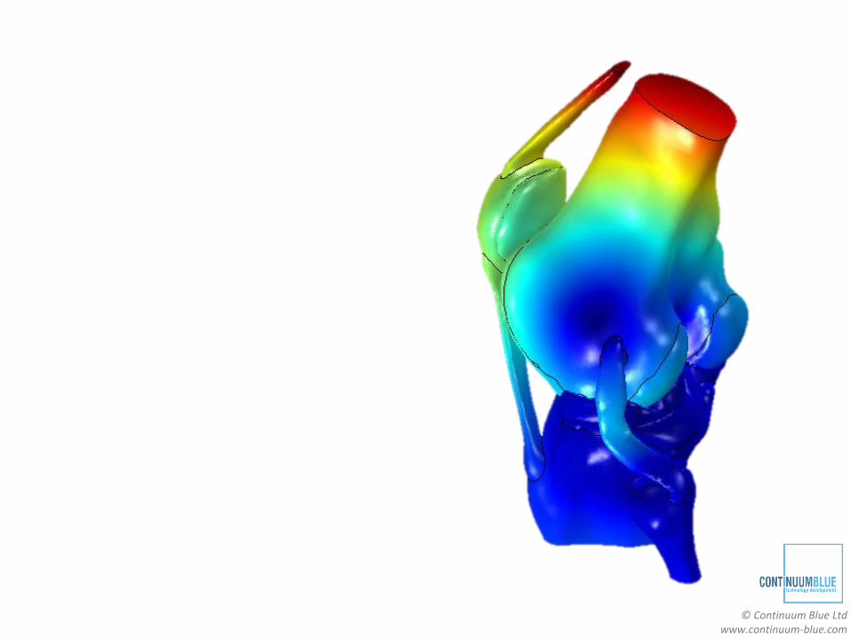
GAIT CYCLE DISPLACEMENT ANIMATION

© Continuum Blue Ltd www.continuum-blue.com
STANDING CASE DISPLACEMENT ANIMATION

© Continuum Blue Ltd www.continuum-blue.com
AXIAL PLANE MOVEMENT AP & ML DISPLACEMENT
Model 1: Natural Intact (no-defect)
Model 2: Partial Meniscectomy 1
(30mm resection)
Model 3: Partial Meniscectomy 2
(35mm resection)
Displacement on Axial Plane
(mm)
Lateral side
Medial side

© Continuum Blue Ltd www.continuum-blue.com
CONTACT PRESSURE ON ARTICULATING SURFACES
Model 1: Natural Intact (no-defect)
Model 2: Partial Meniscectomy 1
(30mm resection)
Model 3: Partial Meniscectomy 2
(35mm resection)
Contact Pressure (MPa)
Lateral side
Medial side

© Continuum Blue Ltd www.continuum-blue.com
1ST PRINCIPAL STRESS MAXIMUM TENSILE
Model 1: Natural Intact (no-defect)
Model 2: Partial Meniscectomy 1
(30mm resection)
Model 3: Partial Meniscectomy 2
(35mm resection)
1st Principal Stress (MPa)
Lateral side
Medial side

© Continuum Blue Ltd www.continuum-blue.com
3RD PRINCIPAL STRESS MAXIMUM COMPRESSIVE
c) Model 3: Partial Meniscectomy 2
(35mm resection)
3rd Principal Stress (MPa)
Model 1: Natural Intact (no-defect)
Model 2: Partial Meniscectomy 1
(30mm resection)
Model 3: Partial Meniscectomy 2
(35mm resection)
Lateral side
Medial side

© Continuum Blue Ltd www.continuum-blue.com
TABULATED DATA CONTACT PRESSURE, STRESSES, DISPLACEMENTS
© Continuum Blue Ltd www.continuum-blue.com
Quantitative
Ranking

© Continuum Blue Ltd www.continuum-blue.com
RANKED EVALUATION WEIGHTED FORMULA
Using the maximum and average data, a method of ranking the virtual surgeries
was developed based on the work by [18].
Ranking method is used to grade the virtual surgeries and assess which is better at
maintaining knee function relative to the intact case.
Ranking method sums the weighted normalized parameter differences between
virtual surgery data & intact reference data, as follows:
(1)
Where:
ϕis the overall ranked value for the virtual surgery being assessed
α is the model parameter being evaluated (stress, displacement or contact pressure)
Parameters with superscript VS represent the virtual surgery model data
Parameters with superscript ND represent the intact (no-defect) model data
From Equation (1), as ϕ 1, the closer the virtual surgery solution is to the intact
reference model.
∅ =
𝑤𝛼𝑖 1 −𝛼𝑖𝑉𝑆 − 𝛼𝑖
𝑁𝐷
𝛼𝑖𝑁𝐷𝑖
𝑤𝛼𝑖𝑖

© Continuum Blue Ltd www.continuum-blue.com
RANKED VALUES OVERALL
Using weighting values of unity (one) for the mean parameters, and two for
the maximum parameters, and substituting these into Equation (1), the
overall ranked values come out as:
• 0.90 for the 30mm resection model.
• 0.86 for 35mm resection model.
Thus these ranked values show that the conserving 30mm resection model
is indeed better, indicating that surgical procedures should be conserving
where possible, as expected.

© Continuum Blue Ltd www.continuum-blue.com
TABULATED DATA PERCENTAGE VARIATION & PARTIAL RANKED VALUES

© Continuum Blue Ltd www.continuum-blue.com
Conclusion &
Discussion

© Continuum Blue Ltd www.continuum-blue.com
CONCLUSION
A knee model has been developed to help assess the change in knee mechanics
and virtual partial meniscectomy surgical options, and a quantitative virtual surgery
ranking method described by Equation (1), is given.
It was found that for the standing load case, the 30mm resection model presents a
closer mechanical response to the ideal intact (no–defect) model.
The overall ranking values obtained were 0.90 and 0.86 for the 30mm and 35mm
resection models, respectively.
This quantitatively shows that the conserving 30mm resection surgery is better
than the 35mm resection surgery, as the closer the ranking value (ϕ) tends to unity,
the closer the solution is to the ideal intact case. Thus, this virtual surgery option
will better restore the function of the knee with a medial menisci defect to that of an
intact knee, under the standing load conditions presented.

© Continuum Blue Ltd www.continuum-blue.com
DISCUSSION
Although the results demonstrate that 30mm conserving resection is beneficial,
only a single defect sight was assessed, where the benefits observed in conserving
the menisci in this region may not necessarily be applicable at other defect sites or
resections sizes. Thus, the assessment of other defect sizes and locations (e.g.
medial vs. lateral and anterior vs. posterior) would be of further interest and benefit,
especially if they can be correlated to clinical data.
In addition, only a small number of stress, displacement and contact pressure
parameters () were utilized in the ranking evaluation. Future work could use
additional data and parameters, such as knee joint centre of rotation, relative
angular changes of the femur and tibia, and ligament stresses. These additional
parameters, combined with a sensitivity analyses on the effect of the weightings
could be done and correlated against clinical data and outcomes, to further develop
the models and the ranking method.
This is a first effort at providing a quantitative method of comparing two surgical
options, future work still needs to be done in order to validate the models and
ranked method against clinical data and patient outcomes. However, the modelling
technique and ranking show potential as a feasible solution for surgeons to use in a
clinical setting to aid to resection options prior to surgery.

© Continuum Blue Ltd www.continuum-blue.com
REFERENCES
1. Gray's Anatomy, The Anatomical Basis of Clinical Reference, 40th Edition (2008) 2. Fedorov et al., 3D Slicer as an Image Computing Platform for the Quantitative Imaging Network. Magnetic Resonance Imaging. Vol. 30(9):1323-41
(2012) 3. 3D Slicer (www.slicer.org) 4. Tissakht and Ahmed, “Tensile Stress-Strain Characteristics of the Human Meniscal Material,” Journal of Biomechanics, Vol. 28 (4):411-422 (1995). 5. Yong Bae et al., “Biomechanical analysis of the effects of medial meniscectomy on degenerative osteoarthritis”, Medical & Biological Engineering &
Computing, Vol. 50 (1):53–60 (2012) 6. F. Reisse, Effect of Malalignement of Knee Joint Contact Mechanics, PhD Thesis, Anglia Ruskin University (2014) 7. Mootanah et al., Development and validation of a computational model of the knee joint for the evaluation of surgical treatments for osteoarthritis,
Computer Methods in Biomechanics and Biomedical Engineering, Vol. 17: 1502–1517(2014) 8. Mononen et al., Effects of Radial Tears and Partial Meniscectomy of Lateral Meniscus on the Knee Joint Mechanics during the Stance Phase of the
Gait Cycle—A 3D Finite Element Study, Journal of Orthopaedic Research, Vol. 31(8):1208–1217(2013) 9. Westermann et al., Effect of ACL Reconstruction Graft Size on Simulated Lachman Testing: A Finite Element Analysis, The Iowa Orthopaedic Journal
Vol. 33:70–77 (2013) 10. Kiapour et al., Finite Element Model of the Knee for Investigation of Injury Mechanisms: Development and Validation, Journal of Biomechanical
Engineering, Vol. 136 (2014) 11. Pena et al., A Three-Dimensional Finite Element Analysis of the Combined Behavior of Ligaments and Menisci in the Healthy Human Knee Joint.
Journal of Biomechanics, Vol. 39(9), pp 1686–1701 (2006) 12. Carey et al., Subject-Specific Finite Element Modeling of the Tibiofemoral Joint Based on CT, Magnetic Resonance Imaging and Dynamic Stereo-
Radiography Data in Vivo, Journal of Biomechanical Engineering, Vol. 136 (2014) 13. Galbusera et al., “Material Models and Properties in the Finite Element Analysis of Knee Ligaments: A Literature Review.” Frontiers in Bioengineering
and Biotechnology Vol. 2 (2014). 14. Sanford et al., Hip, Knee and Ankle Joint Forces in Healthy Weight, Overweight and Obese Individuals During Walking-Computational Biomechanics
for Medicine. Springer, New York, NY (2014) 15. Della Croce et al., Human movement analysis using stereo photogrammetry Part 4: assessment of anatomical landmark misplacement and its effects
on joint kinematics, Gait and Posture, Vol. 21:226–237 (2005) 16. Kadaba et al., Measurement of Lower Extremity Kinematics During Level Walking, Journal of Orthopaedic Research Vol. 8(3):383-92 (1990) 17. Basic Biomechanics of the Musculoskeletal System, Edited by Margareta Nordin DirSci & Victor H. Frankel MD PhD (4th Edition), Lippincott Williams
& Wilkins (2012) 18. Yeoman et al., The Use of Finite Element Methods and Genetic Algorithms in Search of an Optimal Fabric Reinforced Porous Graft System, Annals of
Biomedical Engineering, Vol. 37(11): 2266—2287(2009)

© Continuum Blue Ltd www.continuum-blue.com
Mark Yeoman
Continuum Blue Ltd.
W: www.continuum-blue.com
THANK YOU CONTACT

© Continuum Blue Ltd www.continuum-blue.com
Questions & Answers

© Continuum Blue Ltd www.continuum-blue.com
CONTINUUM BLUE LTD. OVERVIEW
Research & Development
Multiphysics Modeling (FEA/CFD)
Motion & Load Analysis
Material Selection & Optimization
Testing & Assessment
Mechanical Testing
Material Assessment
© Continuum Blue Ltd www.continuum-blue.com
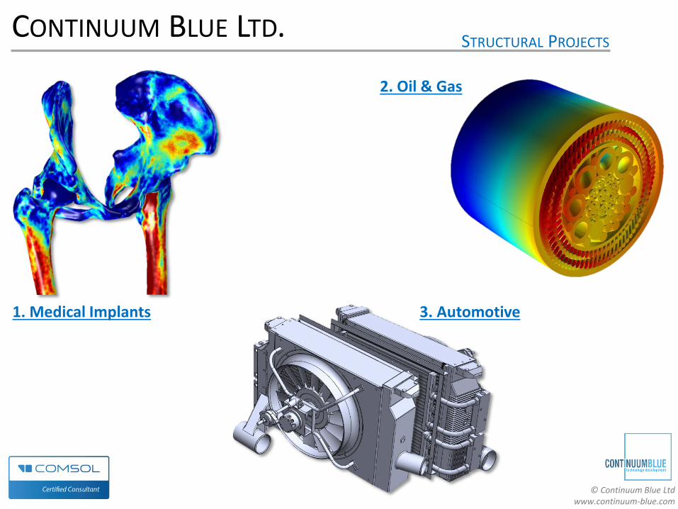
CONTINUUM BLUE LTD. STRUCTURAL PROJECTS
2. Oil & Gas
1. Medical Implants 3. Automotive

© Continuum Blue Ltd www.continuum-blue.com
CONTINUUM BLUE LTD. FLUID FLOW PROJECTS
1. Drug Delivery
2. Bioreactors
Image courtesy: Alchemy Pharmatech Ltd.

© Continuum Blue Ltd www.continuum-blue.com
CONTINUUM BLUE LTD. FLUID FLOW, THERMAL & GAS EMISSION PROJECTS
4. Mould Flow Analysis
• Multiphase flow
• Mixing of Polymers
• Thermal
• Polymer curing
3. Transport
• Vehicle emissions in tunnel
• Air quality analysis