Embed Size (px)
Citation preview

Investigating Improvements to the Y+
Configuration Set
M.A. Holdaway
Kalimba Magic
PO 12974
Tucson, AZ 85732
email: [email protected]
March 28, 2008
Abstract
The previous round of Y+ configuration work primarily optimized the most extendedarray configuration, leaving the intermediate configurations in a bad state. Earlier workattempted to optimize each of the 9 Y+ configurations, but this resulted in a full resolutionarray with very poor properties. The work presented here optimizes the full resolution arrayand two intermediate arrays to achieve much better results, but at the expense of addingmore pads. The sidelobe levels of the two intermediate resolution arrays are about half ofthe previous design, and the beams are within a few percent away from being circular anda few percent away from the desired resolution as determined by a geometrical series. Thisnew design adds 10 more pads - 42 pads for the Y+ configurations rather than the 32 usedlast time - and 12 of the 42 pad positions are in new places that don’t have transporterroad designs. However, these locations all look to be fairly easily accessible.
In addition to the specifications for the three new Y+ arrays, recommendations for threerelated future work projects are given.
1 What the Problem Was for the Y+ Arrays
Over 20% sidelobes. Non-circular beams.
2 What Should We Optimize This Time?
Richard Hills, requested that I optimize the beam parameters for three different Y+ configura-tions - the full resolution array and two transitional arrays between Conway’s highest resolutionarray and the full resolution Y+ array. As each of these three arrays moved 12 antennas outfrom the previous array, this gives us more degrees of freedom than moving 4 antennas does,and hopefully this will allow each subsequent configuration to correct any issues that the arrayis stuck with from the leftover pad positions from the smaller configurations.
Another very important consideration is pad reuse - we want to select pad positions fromthe already approved 32 Y+ pad positions and the additional 4 which were presented butnot approved( they don’t have road designs, but we know that they are accessible. However,
1

this work will necessarily require some new pads if we are to make any improvement over theprevious design. The question is: how many new pads will be required?
2.1 Array Nomenclature
Conway’s configurations are numbers from 1 as the most compact to 20 as the largest. Weformerly numbered the Y+ configurations as Y0 (Conway’s outermost array), Y1 (our mostcompact Y+ array), through Y9 - the most extended Y+ array. In the full array reconfigurationplan, the Y1 through Y9 were renamed 21 - 29.
To distinguish the new Y+ configurations from the old configurations Y1 through Y9, wehave named the three configurations from inside out Y-A, Y-B, and Y-C. This is somewhatunfortunate in that the naming sequence is the opposite of the VLA’s, which starts with theA as the high resolution array, but I would argue that the VLA folks got it wrong.
2.2 Target Resolutions
All sidelobe levels and resolutions are for NATURAL WEIGHTING. Briggs weighting will givesidelobe levels about 60% as large, and significantly smaller beams as well, but people gotconfused when I presented both NATURAL and BRIGGS weighted results last time, so I willnot present any BRIGGS weighted beam parameters.
We simulate observations of an object at declination = -48 degrees, as this builds in aroughly 10% N-S elongation into the optimized array configuration. We simulate +/- 2 hourtracks, partly because the low brightness sensitivity of the high resolution arrays will usuallyrequire long observations to improve the sensitivity, and partly because of the 6-pointed starpattern in the (u,v) plane made by a “Y” configuration - four hours of earth rotation synthesisresults in adjacent points rotating into each other to fill in the (u,v) pattern.
Note that all simulations and beam sizes are for 300 GHz. At 300 GHz, Conway’s config-uration 20 gives a 4 hour track, naturally weighted resolution of 0.08153 arcsec. The old fullresolution Y+ configuration gave a resolution of 0.01659 arcsec. This jump in resolution spaceis spanned if each of the three new configurations has a factor of 1.70 higher resolution thanthe previous configuration.
Array Resolution Y+ Pads OccupiedY0 0.0815 0 Conway’s highest resolution arrayY-A 0.0480 12Y-B 0.0282 24Y-C 0.0166 36 Full resolution Y+
This design has 36 pads built in at the highest level, so without even doing anything wehave 4 more pads than used in the previous design.
3 Optimization Path and Results
The approach used last time did not particularly emphasize the baselines required to get a good(u,v) coverage at 0.0480 arcsec resolution. So the Y3 configuration results in inner sidelobe levelof 0.206 and a beam of 0.0363 x 0.0411 arcsec - ie, on average the baselines in this configurationwere significantly longer than what we need.
2

On the other hand, if we optimize for 12 totally new pad positions plus the outer 38Conway pad positions and seek a Y-A array with low sidelobes and a circular beam close to0.0480 arcsec, we can get a configuration with 0.015 sidelobes and a beam within 5% of circularand within 1 percent of the desired size - ie, a high quality beam which is basically an extensionof the Conway configurations. However, if we nail those pad positions down as part of the Y+configuration, we end up having too many short spacings and we are overly constrained in ourefforts to produce a high quality beam at higher resolution.
So we took a different approach and sought to first optimize the Y-B, and then it is onlyone step away from this configuration to the smaller Y-A array and the full resolution Y-Carray.
The array configurations are included in an appendix to this document, but there is no con-sistent antenna numbering system yet. Pad positions are provided in shifted UTM coordinates:UTMX - 600000 m and UTMY - 7400000 m.
3.1 Y-B Array Configuration: 6 New Pad Positions
For the optimization of the Y-B array with 0.0282 arcsec target resolution, we started with thepreviously “sub-optimized” Y6 array, consisting of 26 Conway pads occupied and 24 Y+ padsoccupied. The beam for this starting configuration had inner sidelobes of 0.1214 (not bad), buta beam shape of 0.0247 x 0.0225 arcsec - not great. In the first stage of optimization, we letall of the outer 24 antennas wander within the confines of the fairly restrictive mask. It shouldbe noted that the mask is inhomogeneous - the inner 5x5 km zone uses Conway’s mask, whichdoes not consider roads at all. The outer part of the mask is built around pre-designed roadsbuilt up iteratively with M3 engineers. Permitting 24 new pads, we were able to get an innersidelobe level of 0.0861 and a beam of 0.0283 x 0.0272 arcsec. The main beam shape/size isvery tight - if we loosened it a bit, the algorithm would be able to do a bit better job on thesidelobe level, and the search for the optimum was not exhaustive - rather I wanted to get anidea of what sort of sidelobe levels were possible to give me a gauge of how many new pads wereally need.
I iteratively “rectified” the array to the old Y+ design - if one of the new pad positionsfell within about 1000 m of a previously defined pad position, I would move the pad positionto the established pad and fix this pad so it would no longer participate in the optimizationprocedure. I left the pad positions which were farther from previously defined pad positions asslack in the system to reoptimize and make up for moving some of the pads to the non-optimalpositions.
After four iterations of rectification and subsequent optimization, I got to a Y-B config-uration which used 6 new pad positions and 18 previously defined pad positions. The innersidelobes were 0.0948 - only marginally higher than the 0.0861 inner sideblobe level which wegot with 24 new pad positions, and somewhat better than the 0.1214 sidelobe level in the oldY6 configuration. The beam shape was significantly better than the Y6 beam - at 0.0278 x0.0256 we are within 6% of the desired resolution and within 8% of a circular beam.
Do we really need all 6 new pad positions? I tried scooting the new pad to the north ofAPEX over to a Y9 pad that had not yet been occupied (the free pad that was closest to anunused pad), and the sidelobe level went up to 0.1029. Not prohibitive.
We’ve already mentioned the new pad near APEX - this is close to the pipeline and wehave a road right there already, so it will be no problem. There are five other new pads in a
3

Configuration inner mid out Bmaj Bmin
[arcsec] [arcsec]
Desired Y-A 0.0480 0.0480Initial Y-A 0.2061 0.1857 0.0365 0.0411 0.036312 antennas free 0.0140 0.0219 0.0377 0.0524 0.0514YY a14 6 antennas free* 0.0391 0.0181 0.0350 0.0512 0.04945 antennas free 0.0831 0.0194 0.0430 0.0489 0.0464
Desired Y-B 0.0282 0.0282Initial Y-B 0.1214 0.1212 0.0334 0.0247 0.022524 antennas free6 antennas free* 0.0951 0.0687 0.0383 0.0278 0.02575 antennas free 0.1029 0.0816 0.0372 0.0274 0.0255
Desired Y-C 0.0166 0.0166Initial Y-C 0.0722 0.0691 0.0441 0.0181 0.016712 antennas free 0.0548 0.0529 0.0383 0.0183 0.0170YY c5 24.STN* 0.0535 0.0553 0.0394 0.0192 0.0168YY c5 26.STN* 0.0693 0.0647 0.0430 0.0180 0.0170
Table 1: Beam parameters for some different possible array configurations. The configurationswith asterisks are the ones we are recommending. “Free antennas” are antennas which aremoveable in order to facilitate the optimization.
cluster to the NE of the central array, between Chajnantor and Chascon. Two of these are tothe north of the pipeline and three are to the south of the pipeline. Access to the northerntwo new pads is through what is labeled here as antenna 34 (this antenna number cannot becorrelated with any other numbering system). Access to the three pads in this cluster south ofthe pipeline is from a road that crosses the nasty arroyo to the north, but south of the pipeline.
3.2 Y-C Array Configuration: No Additional New Pads
For the highest resolution Y+ array, or Y-C, we are aiming for a resolution of 0.0166 arcsec.We made an initial Y-C configuration from the Y-B configuration and 12 of the previouslydefined Y+ pads.
, evacuating the inner 12 Conway pads and occupied 12 more of the previously defined Y+pads, and then optimized for the positions of the outer 12 antennas.
++Sidelobes: in: 0.0548 mid: 0.0529 out: 0.0383 bmaj: 0.0183 bmin: 0.017As we did for the Y-B configuration, we rectified to the existing Y9 configuration’s stations.
3.3 Y-A Array Configuration: 6 New Pad Positions
OK, we saved the hard part for last.NOTICE: table numbers of YY a14 don’t quite match the plot for 6 free an-
tennas. Check this!!!!
NOTICE: we lost the beam data for Y-B with 24 free antennas.
4

Figure 1: The pipeline slicing through the ALMA site showing the numbered antennas for thefavored Y-B configuration which reuses 18 pads from the previously presented Y9 configuration(open squares), but also 6 new pads.
5

Figure 2: One possible Y-C array, YY c5 24, with lower sidelobes.
6

Figure 3: One possible Y-C array, YY c5 26, with a more circular beam.
7

Figure 4: Measures of configuration quality as a function of the number of new pads for possibleY-A configuration. Note that I can change the relative weighting for sidelobe level and beamsize/shape in the optimization. In the configurations with more freely-placed antennas, I amguessing that the algorithm could get extra low sidelobes at the expense of resolution, and anarray with a more nearly correct resolution could be obtained at the expense of sidelobe level.
8

Figure 5: Recommended Y-A configuration using 6 Y-B pads and 6 new pads.
9

Figure 6: Snapshot coverage for configuration Y-A. ALL UV plots should be SQUARE, butthe software didn’t make them that way.
10
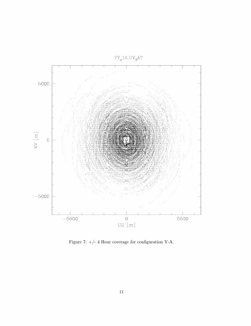
Figure 7: +/- 4 Hour coverage for configuration Y-A.
11

Figure 8: Snapshot coverage for configuration Y-B.
12

Figure 9: +/- 4 Hour coverage for configuration Y-B.
13

Figure 10: Snapshot coverage for configuration Y-C/24.
14

Figure 11: +/- 4 Hour coverage for configuration Y-C/24.
15

Figure 12: Snapshot coverage for configuration Y-C/26.
16

Figure 13: +/- 4 Hour coverage for configuration Y-C/26.
17

4 Pad Accounting
Total Y+ pads now: 42. We originally wanted 36 Y+ pads, 6 months ago we scaled back to32. SO, 42 is 6 more than the original 36, or 10 more than the more recent 32 Y+ pads.
We have 12 pads in regions which have not been looked at before, but these will probablybe OK - we must design roads and go and visit these sites.
Some pads which have designed roads are now being unused. Four pads which were aban-doned (ie, when we went from 36 to 32 Y+ pads) are now being used.
I’ll write this a bit better which I am awake.
5 Proposed Additional Work
• Optimize the sub-configurations. Configuration Y-A is made by moving 12 of theinnermost antennas in Conway’s outermost configuration and sending them out along the“arms of the Y+”. Y-B is made by moving 12 more antennas out, and Y-C, the highestresolution Y+ array configuration, is made from 12 more antennas moved outwards.However, we expect to be able to make 4 antenna moves a day, so we need to optimizefor Y-A-1, Y-A-2, and Y-A-3 arrays - actually Y-A-3 is the Y-A configuration we havespecified here.
We should not perform this optimization until after new pad positions have been ac-cepted. There is no time pressure on this job, as it does not impact any pad positions orconstruction, but it should be done before my NRAO-issued computer running AIPS++dies. I will have some time to do this in August or September. I estimate this to be a 40hour project.
• Optimize the inner antenna pad evacuation scheme to improve short baseline
coverage. Conway’s spiral configurations follow a strict rule in selecting the antenna topick up and move: antennas are taken off the innermost occupied pads and moved outto outer pads. The Y+ reconfiguration scheme generally follows that rule, with a majorexception: there are three pairs of antennas which give very short baselines - 80m for theY+ - in different orientations to help with flux calibration. Reconfiguration passes theantennas on these six pads by as less central antennas are evacuated to the Y+ positions.
Single configuration imaging is not required for ALMA, as observations from multipleconfigurations and even mosaicing with total power data can be used if we are imaginga very large object with lots of fine structure. On the other hand, it is to our advantageto stretch our single configuration imaging capabilities if possible. Cross calibration ofdatasets taken at different times results in lost efficiency. The atmosphere and the fluxcalibrator could be very different. But perhaps the most important thing is that somehigh resolution observations will be of variable objects which we would prefer to observeat discrete and well-defined times with a single configuration.
Changing the detailed order of antenna pad evacuation will have a very small effect onthe beam properties we have already optimized for: PSF sidelobe levels and main beamshapes and sizes. However, improving the short baseline (u,v) coverage could have majorimpact on imaging for single configuration observations. In effect, work done in this
18

direction will modestly increase the number of high resolution projects which can meettheir scientific objectives with single configuration imaging.
We should not perform this optimization until after new pad positions have been ac-cepted. There is no time pressure on this job, as it does not impact any pad positions orconstruction, but it should be done before my NRAO-issued computer running AIPS++dies. I will have some time to do this in August or September. I estimate this to be a40-80 hour project.
• /bf Work with someone in Socorro to transcribe this software from AIPS++/glish intoCASA/Python. At some point, this old computer loaded with AIPS++ and SuperMongoand all the scripts I use for this work is going to die. It would probably be good to getthis code translated into a more modern system. I have no real experience in CASA, soI should probably sit and work with someone who does. I am supposing this could take25-50 hours, and would involve some travel to Socorro. If this work is performed first,then you could get someone else to perform the sub-configuration optimization and shortbaseline optimization.
A Configurations
19

UTMx - 600000 UTMy - 7400000 Altitude Padm [m] [m]27320.0 52981.0 5025.1 128242.0 52816.0 5015.9 227593.0 53611.0 5031.0 327615.0 52488.0 5028.0 428287.0 53384.0 5016.4 527237.0 53285.0 5026.9 628261.0 52578.0 5019.8 727878.0 53858.0 5029.4 827369.0 52511.0 5019.2 928488.0 53134.0 5007.2 1027265.0 53482.0 5026.1 1128003.0 52241.0 5018.9 1228166.0 53836.0 5022.7 1327021.0 52792.0 5011.4 1428593.0 52742.0 5012.6 1527364.0 53932.0 5025.9 1627640.0 52147.0 5028.4 1728567.0 53703.0 5010.7 1826779.0 53196.0 5013.0 1928571.0 52164.0 5030.1 2027725.0 54268.0 5029.5 2127047.0 52073.0 5015.2 2228948.0 53327.0 4984.2 2326693.0 53811.0 5011.8 2428199.0 51828.0 5035.1 2528283.0 54433.0 5020.5 2626543.0 52370.0 4992.9 2729061.0 52702.0 4998.0 2826952.0 54338.0 5024.2 2927686.0 51501.0 5016.7 3028978.0 54297.0 4990.6 3126124.0 52986.0 4992.9 3229178.0 51892.0 5058.6 3327389.0 55123.0 5032.6 3426640.0 51943.0 4987.6 3527685.0 52525.0 5029.7 3628211.0 53421.0 5019.3 3727240.0 53368.0 5027.1 3830815.8 55710.4 4902.8 3930240.0 54330.0 4928.1 4027050.0 56280.0 5048.0 4125068.7 55189.3 4958.9 4229490.2 50388.2 5009.5 4329707.6 52399.0 5006.4 4427583.8 51083.3 5002.9 4529623.7 52088.1 5028.7 4628092.6 55140.1 5021.8 4728707.2 54952.2 4988.3 4830940.0 53180.0 4931.0 4929734.6 53889.7 4948.7 50
Table 2: Pad positions for Y-A14.20

UTMx - 600000 UTMy - 7400000 Altitude Padm [m] [m]27364.0 53932.0 5025.9 127640.0 52147.0 5028.4 228567.0 53703.0 5010.7 326779.0 53196.0 5013.0 428571.0 52164.0 5030.1 527725.0 54268.0 5029.5 627047.0 52073.0 5015.2 728948.0 53327.0 4984.2 826693.0 53811.0 5011.8 928199.0 51828.0 5035.1 1028283.0 54433.0 5020.5 1126543.0 52370.0 4992.9 1227615.0 52488.0 5028.0 1328287.0 53384.0 5016.4 1427237.0 53285.0 5026.9 1529061.0 52702.0 4998.0 1626952.0 54338.0 5024.2 1727686.0 51501.0 5016.7 1828978.0 54297.0 4990.6 1926124.0 52986.0 4992.9 2029178.0 51892.0 5058.6 2127389.0 55123.0 5032.6 2226640.0 51943.0 4987.6 2327685.0 52525.0 5029.7 2428211.0 53421.0 5019.3 2527240.0 53368.0 5027.1 2630815.8 55710.4 4902.8 2731734.4 51128.6 4958.6 2825068.7 55189.3 4958.9 2931358.0 55681.0 4895.3 3026659.1 56623.9 5031.7 3130178.0 48780.1 4835.3 3231703.0 57742.3 4853.9 3330121.0 55276.0 4922.6 3431778.0 56289.0 4870.5 3529490.2 50388.2 5009.5 3625901.9 57210.2 5003.5 3723451.0 55040.0 4871.0 3832179.4 56591.2 4827.9 3932280.0 47663.0 4761.1 4030358.7 54983.4 4910.4 4130780.0 53750.0 4917.7 4224082.0 55048.0 4916.4 4330940.0 53180.0 4931.0 4430240.0 54330.0 4928.1 4530645.7 54376.1 4904.2 4631778.7 58902.7 4843.9 4727050.0 56280.0 5048.0 4831269.6 50944.9 4917.4 4931556.8 58399.5 4869.6 50
Table 3: Pad positions for Y-B5.21

UTMx - 600000 UTMy - 7400000 Altitude Padm [m] [m]27615.0 52488.0 5028.0 128287.0 53384.0 5016.4 227237.0 53285.0 5026.9 329061.0 52702.0 4998.0 426952.0 54338.0 5024.2 527686.0 51501.0 5016.7 628978.0 54297.0 4990.6 726124.0 52986.0 4992.9 829178.0 51892.0 5058.6 927389.0 55123.0 5032.6 1026640.0 51943.0 4987.6 1127685.0 52525.0 5029.7 1228211.0 53421.0 5019.3 1327240.0 53368.0 5027.1 1430815.8 55710.4 4902.8 1531734.4 51128.6 4958.6 1625068.7 55189.3 4958.9 1731358.0 55681.0 4895.3 1826659.1 56623.9 5031.7 1930178.0 48780.1 4835.3 2031703.0 57742.3 4853.9 2130121.0 55276.0 4922.6 2231778.0 56289.0 4870.5 2329490.2 50388.2 5009.5 2425901.9 57210.2 5003.5 2523451.0 55040.0 4871.0 2632179.4 56591.2 4827.9 2732280.0 47663.0 4761.1 2830358.7 54983.4 4910.4 2930780.0 53750.0 4917.7 3024082.0 55048.0 4916.4 3130940.0 53180.0 4931.0 3230240.0 54330.0 4928.1 3330645.7 54376.1 4904.2 3426159.9 57081.8 5010.4 3527050.0 56280.0 5048.0 3631269.6 50944.9 4917.4 3731556.8 58399.5 4869.6 3832742.0 59525.3 4815 3931275.9 46977.7 4766.8 4032668.2 51111.2 4970.7 4123040.0 54968.0 4845.8 4231114.9 47761.9 4763.6 4321584.0 54319.0 4707.3 4431778.7 58902.7 4843.9 4521305.4 54940.9 4687.9 4633309.9 62869.2 4834.5 4720125.0 53657.0 4566.7 4834062.0 47310.0 4728.4 4930365.9 48430.8 4805.1 50
Table 4: Pad positions for Y-C5-24.22

UTMx - 600000 UTMy - 7400000 Altitude Padm [m] [m]27615.0 52488.0 5028.0 128287.0 53384.0 5016.4 227237.0 53285.0 5026.9 329061.0 52702.0 4998.0 426952.0 54338.0 5024.2 527686.0 51501.0 5016.7 628978.0 54297.0 4990.6 726124.0 52986.0 4992.9 829178.0 51892.0 5058.6 927389.0 55123.0 5032.6 1026640.0 51943.0 4987.6 1127685.0 52525.0 5029.7 1228211.0 53421.0 5019.3 1327240.0 53368.0 5027.1 1430815.8 55710.4 4902.8 1531734.4 51128.6 4958.6 1625068.7 55189.3 4958.9 1731358.0 55681.0 4895.3 1826659.1 56623.9 5031.7 1930178.0 48780.1 4835.3 2031703.0 57742.3 4853.9 2130121.0 55276.0 4922.6 2231778.0 56289.0 4870.5 2329490.2 50388.2 5009.5 2425901.9 57210.2 5003.5 2523451.0 55040.0 4871.0 2632179.4 56591.2 4827.9 2732280.0 47663.0 4761.1 2830358.7 54983.4 4910.4 2930780.0 53750.0 4917.7 3024082.0 55048.0 4916.4 3130940.0 53180.0 4931.0 3230240.0 54330.0 4928.1 3330645.7 54376.1 4904.2 3433085.5 61307.3 4828.6 3527050.0 56280.0 5048.0 3631269.6 50944.9 4917.4 3731556.8 58399.5 4869.6 3832742.0 59525.3 4815 3931275.9 46977.7 4766.8 4032668.2 51111.2 4970.7 4123040.0 54968.0 4845.8 4231114.9 47761.9 4763.6 4321584.0 54319.0 4707.3 4431778.7 58902.7 4843.9 4521305.4 54940.9 4687.9 4633309.9 62869.2 4834.5 4720125.0 53657.0 4566.7 4834062.0 47310.0 4728.4 4930365.9 48430.8 4805.1 50
Table 5: Pad positions for Y-C5-26.23