Embed Size (px)
Citation preview

Investigating Basic Circuits
Pre-Activity Discussion
© 2014 Project Lead The Way, Inc.Digital Electronics

This Presentation Will…
2
• Introduce you to basic circuits and their symbols.• Introduce you to components and equipment that are
fundamental to understanding circuits.• Define voltage, current, and resistance.• Prepare you for Activity 1.1.2 Investigating Basic Circuits

Investigating Basic Circuits
3
• You may have studied electricity and circuits in others classes.
Physical Science
PLTW – Gateway – ME
Chemistry
Physics
• This guided activity assumes that you have no prior knowledge of electricity.
• If you have studied circuits before, it can act as a refresher to help you start thinking about circuits again.

Reflective Questions
Throughout this activity keep considering…• What are some of the basic components that make up
simple circuits and what do they do?• What are the important characteristics of a circuit and
how do I measure different parts of a circuit?• How do I work safely with circuits?• How do I measure voltage in a circuit? • How does the arrangement of components affect the
characteristics of the circuit?• How can I use calculations to design circuits before I
start creating one?
4

Equipment and Tools
In this activity you will be introduced to the equipment, concepts, and skills that are foundations in the study of electronics.
• Components - (Discrete Components) Simple electronic devices that affect electrons in a circuit.
• Breadboards - Reusable platforms for prototyping circuits temporarily without soldering.
• Measurement Tools – The Digital Multimeter (DMM) is widely used to measure: – Current (I)– Voltage (V)– Resistance (R)
5
R
VI
V
I R
+ -

Electronic Components
6

Basic Breadboards
7
A breadboard, sometimes called a protoboard, is a reusable platform to temporarily build electronic circuits.

Advanced Breadboards
8
Digital design tools that already have common components in place for you. They also sometimes have advanced programming ability to create large circuits.
NI Digital Logic Board (DLB) NI Protoboard

How a Breadboard Works
• Electric component leads and the wire used to connect them are inserted into holes that are arranged in a grid pattern on the surface of the breadboard.
• A series of internal metal strips serve as jumper wires. They connect specific rows of holes.
9
Cut-Away View
Top View

Breadboard Connections
10

Printed Circuit Boards (PCB)
11
• Connects electronic components using conductive pathways etched from copper sheets laminated onto a non-conductive substrate.
• Components are then attached through soldering.

Why Breadboard?
1) It takes less time (and money) to breadboard a circuit than to design and fabricate a printed circuit board (PCB).
Because of the cost, a PCB should be reserved for the final working design.
2) As a complement to circuit simulation, breadboarding allows the designer to see how, and if, the actual circuit functions.
12

Why Breadboard?
3) Breadboards give the designer the ability to quickly change components during development and testing, such as swapping resistors or capacitors of different values.
4) A breadboard allows the designer to easily modify a circuit to facilitate measurements of voltage, current, or resistance.
13

Breadboard: Guidelines and Tips
• Use as few jumper wires as possible. The breadboard should be used to make the majority of the connections between the components.
• Keep jumper wires as short as possible. A jumble of wires is difficult to troubleshoot.
• Breadboard a circuit so that it looks as close as possible to the layout of the schematic circuit. This makes troubleshooting easier.
14
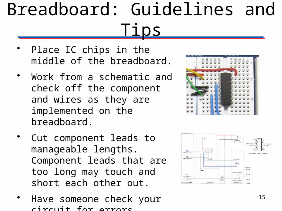
Breadboard: Guidelines and Tips
• Place IC chips in the middle of the breadboard.
• Work from a schematic and check off the component and wires as they are implemented on the breadboard.
• Cut component leads to manageable lengths. Component leads that are too long may touch and short each other out.
• Have someone check your circuit for errors.
15

Digital Multimeters (DMM)
Used to measure Voltage, Current, and Resistance
Symbol
(V ---) Voltage Direct Current
(V ~) Voltage Alternating Current
(A ---) Current
(Ω) Resistance
In this activity you will learn how to measure voltage. 16
Traditional Digital Multimeter (DMM)

Digital Multimeters (DMM)
Data Acquisition Modules (DAQs) turn your computer into many useful tools that were typically different pieces of equipment in the past. (Including a DMM)
17Digital MiniSystem (DMS)NI myDAQ + Protoboard
Digital Multimeter (DMM)

How to Properly Use a DMM
• It is critical to understand the proper way to measure
– Current (I)– Voltage (V)– Resistance (R)
• Placing the leads (red and black) in the improper place will give you incorrect readings and possible damage the DMM
• In this activity you will learn to accurately measure voltage. 18

Circuit Diagrams
In this activity you will be introduced to the basic components of a circuit and how they are arranged. Each component has a symbol that can be used to create a circuit diagram.
Circuit diagrams and calculations help a circuit designer figure out the characteristics of the circuit before they begin prototyping or breadboarding the circuit.
19

Circuit Diagram Symbols
20
Analog Power Sources
Digital Power Sources
Discrete Components
Voltage Source
Digital Ground
Resistor
Light Emitting Diode
Voltage Source
Ground
+
-
In this circuit example, we imagine the flow of conventional current to be a positive charge (+) moving from the positive terminal of the battery to the negative terminal of the battery or ground.
A circuit must have a complete path from voltage source to ground.

Voltage, Current, & Resistance
21
Andre Ampere1775-1836
French Physicist
Current – Current is the flow of electrical charge through an electronic circuit. The direction of a current is opposite to the direction of electron flow. Current is measured in AMPERES (AMPS).

Voltage
22
Alessandro Volta1745-1827
Italian Physicist
Voltage – Voltage is the electrical force that causes current to flow in a circuit. It is measured in VOLTS.

Resistance
23
Georg Simon Ohm1789-1854
German Physicist
Resistance – Resistance is a measure of opposition to current flow. It is measured in Ohms.

Reflective Questions
Throughout this activity keep considering…• What are some of the basic components that make up
simple circuits and what do they do?• What are the important characteristics of a circuit and
how do I measure different parts of a circuit?• How do I work safely with circuits?• How do I measure voltage in a circuit? • How does the arrangement of components affect the
characteristics of the circuit?• How can I use calculations to design circuits before I
start creating one?
24

Investigating Basic Circuits
• Now that you are familiar with some of the equipment and concepts that are fundamental to the study of electronics, you are ready to start exploring them in more detail.
• Be sure to follow all safety guidelines and instructor directions for Activity 1.1.2 Investigating Basic Circuits.
• Answer all questions in is as much detail as you can. You will not be graded on the accuracy of your answers for this introductory activity.
• You answer will help shape the class discussion at the conclusion of this activity.
• Now let’s explore electrical circuits.
25