Embed Size (px)
Citation preview
Journal of Advanced Engineering Trends (JAET), Vol. 39, No. 1. January 2020
- 1 -
INVESTIGATE VEHICLE DESIGN PARAMETERS EFFECT ON
DYNAMIC VEHICLE STABILITY
Mina. M. Ibrahim*, K. A. Abd El-Gwwad, M. M. M. Salem, and M. Mourad
Automotive and Tractors Eng. Dept., Faculty of Engineering, Minia University, El-Minia Egypt, 61111
E-mail: * [email protected]
ABSTRACT
In this paper, a two degree of freedom linear vehicle model is proposed to investigate
dynamic vehicle stability under varies vehicle maneuvers. The simulation is developed using
MATLAB/Simulink application program to predict the vehicle dynamic stability under different
maneuvers. To investigate vehicle stability, the Steering wheel angle is chosen to be the primary
model input for the analysis procedures. The developed model is validated via Step steer input.
Moreover, a new typical steer wheel angle is developed to examine highway predicted vehicle
output within its maneuver. The vehicle dynamic outputs, namely, yaw rate and lateral
acceleration are adopted for all the investigated maneuvers. It is found that the vehicle design
parameters such as changing the vehicle center of gravity (CG) position, vehicle mass, tire
cornering stiffness and vehicle speed have a significant influence on the vehicle dynamic
stability. Change in vehicle center of gravity position is the most parameter has an influence in
vehicle stability dynamics. 10% forward and reward in the C.G position change in under steering
gradient, it changes steering in vehicle model from under steering type to over steering type, on
the other hand, vehicle mass change 10% change in vehicle mass has the latest influence in
vehicle stability dynamic. Others have a different rate effect on vehicle dynamic stability.
Keywords: Yaw rate, vehicle stability dynamics, parameters.
1 INTRODUCTION
In this research, vehicle stability is
investigated during its maneuvering versus
steering excitations (step input and typical
steer angle) which are used as the major
input for the proposed vehicle model. In this
manner, a complete parametrical analysis is
needed regarding a complete understanding
of the vehicle stability characteristics and
sensitivity. Furthermore, a conflict analysis
can illustrate the trade-off between the
vehicle stability indices during different
conditions and with respect to the design
parameters. Several researchers had studied
vehicle stability either theoretically via the
simulation software like the
MATLAB/Simulink or experimentally
including both the laboratory and on-field
experiments[1].Dynamic stability of
vehicles depends on varies maneuver
conditions such as traction, braking, and
cornering. knowingly, both the yaw rate and
lateral acceleration are usually used to
represent and investigate the theoretical
handling performance for vehicle models
which defined the stability region under
varies maneuver features [2].Lateral stability
and vehicle handling performance have a
significant notice in most automotive
research recently. Many sever accident was
resulted due to vehicle in stability during
maneuvering[3]. In the vehicular stability
academic literature, several researchers have
analyzed the vehicle stability and handling
trends considering varies steering inputs
including the step steer, triangle pulse, right
angle, triangle pulse, rectangular pulse,
sinusoidal pulse, and sinusoidal sweep
[4].The steering system is the interface
between the vehicle and road. In the rubber-
wheeled vehicle, steering systems are
represented by a mechanical linkage
between the driver, vehicle and the front
wheel[5]. Steering input is an indicationof
the type of road perturbation and defines the
torque on both the road and wheel, and it
varies depending on road condition[6].
Vehicle design parameters including
Journal of Advanced Engineering Trends (JAET), Vol. 39, No. 1. January 2020
- 2 -
geometrical and suspension parameters have
a remarked effect on vehicle stability and
handling during the maneuvering and real
driving.Theladen and un laden conditions
during vehicle maneuvering can highly
affectvehicl estability[7, 8].Center of gravity
(C.G) is also a critical parameter which
affects vehiclestability eventually. The
change is the C.G position can also affect
the vehicular stability and handling based on
the vehicle body mass distribution since the
change in vehicle mass distribution on both
the front and rear wheels have a significant
effect on vehicle handling and stability[9,
10].Traveling on roads, vehicle speeds and
cornering radius presented remarked effect
on vehicle stability including the yaw rate
and lateral acceleration which can be
estimated during the simulations under
varies speed and steering maneuver [11].
Based on the aforementioned key
observations from the previously published
literature, this paper presented complete
parametrical and conflict analyses including
the geometrical and vehicle design
parameters were conducted. During the
simulations, a 2-DOFs bicycle-vehicle
model was implemented and verified and
thereafter two steering modes were used to
examine the sensitivity of vehicular stability
and handling performances. In this manner,
both the yaw rate and vehicle lateral
acceleration were mainly considered as the
vehicle stability indices.
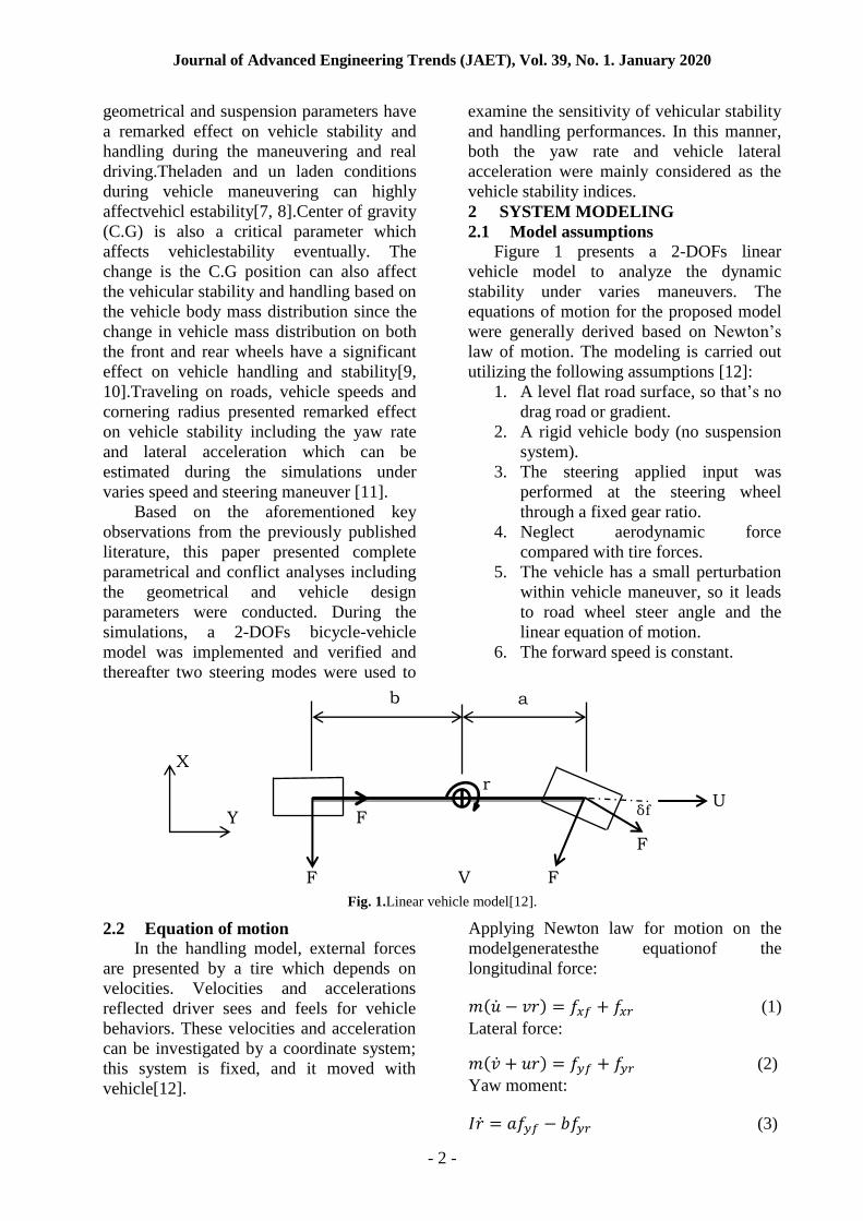
2 SYSTEM MODELING
2.1 Model assumptions
Figure 1 presents a 2-DOFs linear
vehicle model to analyze the dynamic
stability under varies maneuvers. The
equations of motion for the proposed model
were generally derived based on Newton’s
law of motion. The modeling is carried out
utilizing the following assumptions [12]:
1. A level flat road surface, so that’s no
drag road or gradient.
2. A rigid vehicle body (no suspension
system).
3. The steering applied input was
performed at the steering wheel
through a fixed gear ratio.
4. Neglect aerodynamic force
compared with tire forces.
5. The vehicle has a small perturbation
within vehicle maneuver, so it leads
to road wheel steer angle and the
linear equation of motion.
6. The forward speed is constant.
Fig. 1.Linear vehicle model[12].
2.2 Equation of motion
In the handling model, external forces
are presented by a tire which depends on
velocities. Velocities and accelerations
reflected driver sees and feels for vehicle
behaviors. These velocities and acceleration
can be investigated by a coordinate system;
this system is fixed, and it moved with
vehicle[12].
Applying Newton law for motion on the
modelgeneratesthe equationof the
longitudinal force:
( ) (1)
Lateral force:
( ) (2)
Yaw moment:
(3)
r U
V
a b
F
yr
F
xr F
F
yf
X
Y δf
Journal of Advanced Engineering Trends (JAET), Vol. 39, No. 1. January 2020
- 3 -
This case study assumes that the forward
speed U constant, so the equation (1)
disappeared, so the equations are:
( ) (4)
(5)
Where u is forward speed, and it was in
x-direction, v is the lateral velocity, and it
was in y-direction, r is the angular velocity
(yaw rate),and it was in z-direction, and
the lateral force on front and rear wheel
respectively, m was defined as vehicle mass
and I was defined as yaw inertia, a and b
was defined as the distance between the
center line of front and rear wheel to the
point of the center of gravity of vehicle
respectively.
Then we investigate tire forces which it in
terms of the system:
(6)
(7)
Where Cf and Cr was defined as
cornering stiffness for front and rear wheel
respectively, and was defined as slip
angle for front and rear wheel respectively.
Slip angle can also be defined as:
(8)
(9)
From Eqs. (8) and (9) equation of motion
will be:
( ) ( )
( )
(10)
( )
( )
(11)
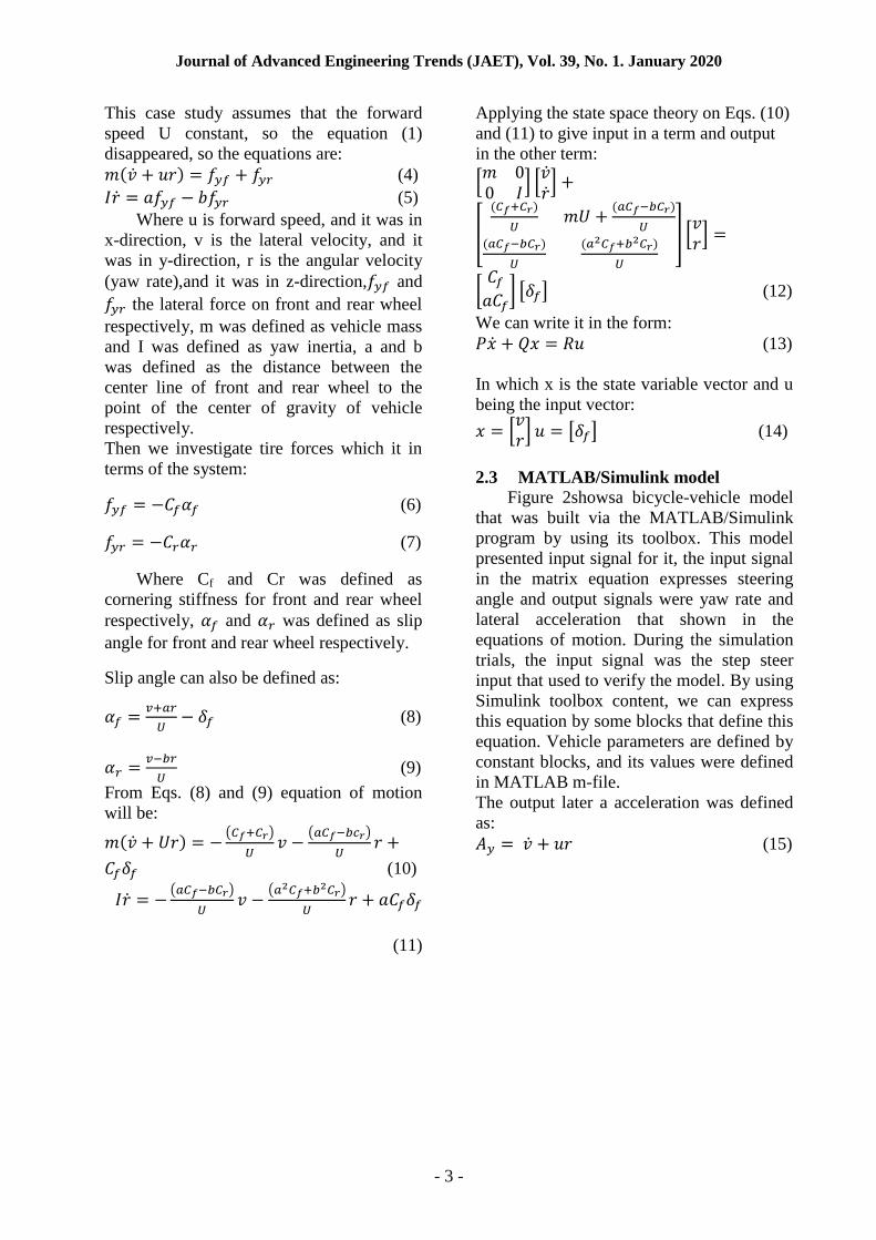
Applying the state space theory on Eqs. (10)
and (11) to give input in a term and output
in the other term:
[
] [ ]
[
( )
( )
( )
( )
] [ ]
[
] [ ] (12)
We can write it in the form:
(13)
In which x is the state variable vector and u
being the input vector:
[ ] [ ] (14)
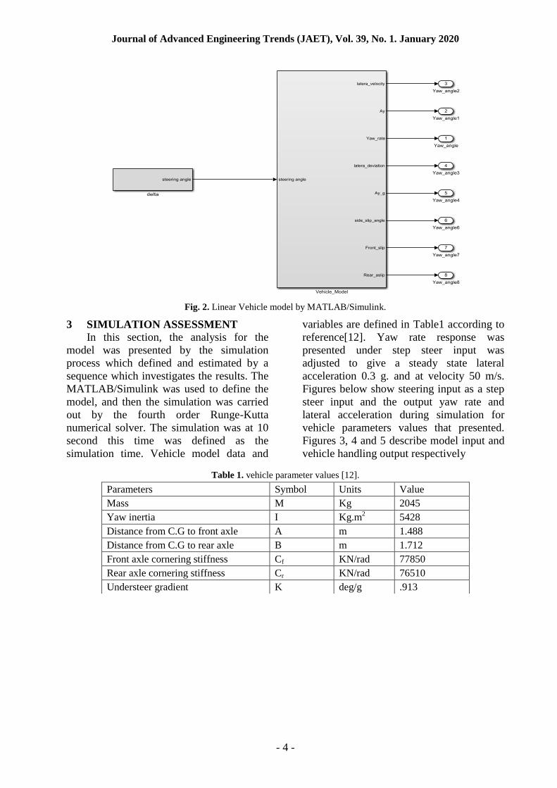
2.3 MATLAB/Simulink model
Figure 2showsa bicycle-vehicle model
that was built via the MATLAB/Simulink
program by using its toolbox. This model
presented input signal for it, the input signal
in the matrix equation expresses steering
angle and output signals were yaw rate and
lateral acceleration that shown in the
equations of motion. During the simulation
trials, the input signal was the step steer
input that used to verify the model. By using
Simulink toolbox content, we can express
this equation by some blocks that define this
equation. Vehicle parameters are defined by
constant blocks, and its values were defined
in MATLAB m-file.
The output later a acceleration was defined
as:
(15)
Journal of Advanced Engineering Trends (JAET), Vol. 39, No. 1. January 2020
- 4 -
Fig. 2. Linear Vehicle model by MATLAB/Simulink.
3 SIMULATION ASSESSMENT
In this section, the analysis for the
model was presented by the simulation
process which defined and estimated by a
sequence which investigates the results. The
MATLAB/Simulink was used to define the
model, and then the simulation was carried
out by the fourth order Runge-Kutta
numerical solver. The simulation was at 10
second this time was defined as the
simulation time. Vehicle model data and
variables are defined in Table1 according to
reference[12]. Yaw rate response was
presented under step steer input was
adjusted to give a steady state lateral
acceleration 0.3 g. and at velocity 50 m/s.
Figures below show steering input as a step
steer input and the output yaw rate and
lateral acceleration during simulation for
vehicle parameters values that presented.
Figures 3, 4 and 5 describe model input and
vehicle handling output respectively
Table 1. vehicle parameter values [12].
Parameters Symbol Units Value
Mass M Kg 2045
Yaw inertia I Kg.m2
5428
Distance from C.G to front axle A m 1.488
Distance from C.G to rear axle B m 1.712
Front axle cornering stiffness Cf KN/rad 77850
Rear axle cornering stiffness Cr KN/rad 76510
Understeer gradient K deg/g .913
Journal of Advanced Engineering Trends (JAET), Vol. 39, No. 1. January 2020
- 5 -
Fig. 3. (a) Step steer wheel angle, (b) typical steering wheel angle.
Fig. 4. Output verification comparison with the standard model by Crolla; (a) yaw rate stability for step steer angle
at speed of 50 m/s, (b) lateral acceleration for step steer angle at 50 m/s speed.
4 RESULTS AND DISCUSSION
Vehicle parameters have an effect in
dynamic vehicle stability during vehicle
maneuvers, any changes in parameters
values effect on vehicle performance during
the maneuver. In this section, it will discuss
the performance of the vehicle under a
typical input that was published in
reference[13]. Typical input was adjusted to
give a steady state lateral acceleration 0.3 g,
typical input carried out to investigate the
performance of a vehicle model under this
maneuver as a simulation for an actual
condition maneuver. Figure3b shows the
wheel steering angle input for typical
steering angle, while the lateral acceleration
is shown in Fig. 5b and it goes to zeros as a
steady state condition like steering angle.
The yaw rate stability is presented in Fig.
5ain which its trend is peaked and then go to
zeros respecting to the steady state
condition.
Fig. 5.Handling performance output for typical wheel steer angle at vehicle speed 50 m/s; (a) yaw rate, (b) lateral
acceleration.
Journal of Advanced Engineering Trends (JAET), Vol. 39, No. 1. January 2020
- 6 -
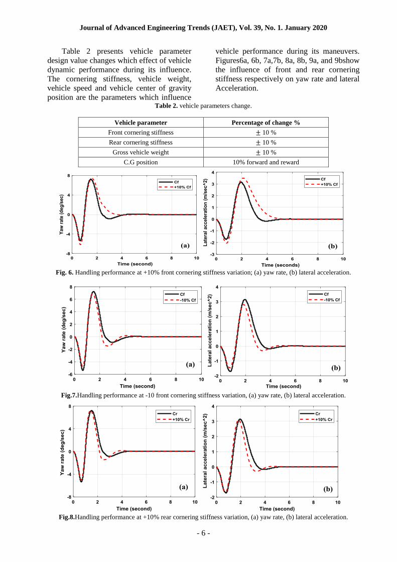
Table 2 presents vehicle parameter
design value changes which effect of vehicle
dynamic performance during its influence.
The cornering stiffness, vehicle weight,
vehicle speed and vehicle center of gravity
position are the parameters which influence
vehicle performance during its maneuvers.
Figures6a, 6b, 7a,7b, 8a, 8b, 9a, and 9bshow
the influence of front and rear cornering
stiffness respectively on yaw rate and lateral
Acceleration.
Table 2. vehicle parameters change.
Fig. 6. Handling performance at +10% front cornering stiffness variation; (a) yaw rate, (b) lateral acceleration.
Fig.7.Handling performance at -10 front cornering stiffness variation, (a) yaw rate, (b) lateral acceleration.
Fig.8.Handling performance at +10% rear cornering stiffness variation, (a) yaw rate, (b) lateral acceleration.
Vehicle parameter Percentage of change %
Front cornering stiffness 10 %
Rear cornering stiffness 10 %
Gross vehicle weight 10 %
C.G position 10% forward and reward
Journal of Advanced Engineering Trends (JAET), Vol. 39, No. 1. January 2020
- 7 -
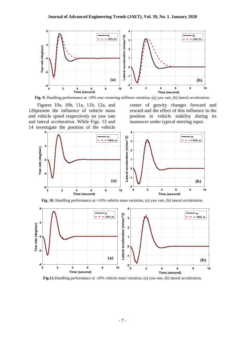
Fig. 9. Handling performance at -10% rear cornering stiffness variation, (a) yaw rate, (b) lateral acceleration.
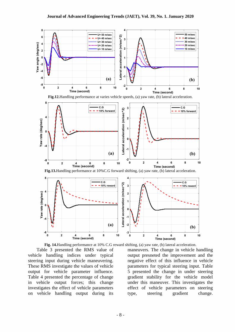
Figures 10a, 10b, 11a, 11b, 12a, and
12bpresent the influence of vehicle mass
and vehicle speed respectively on yaw rate
and lateral acceleration. While Figs. 13 and
14 investigate the position of the vehicle
center of gravity changes forward and
reward and the effect of this influence in the
position in vehicle stability during its
maneuver under typical steering input.
Fig. 10. Handling performance at +10% vehicle mass variation, (a) yaw rate, (b) lateral acceleration.
Fig.11.Handling performance at -10% vehicle mass variation, (a) yaw rate, (b) lateral acceleration.
Journal of Advanced Engineering Trends (JAET), Vol. 39, No. 1. January 2020
- 8 -
Fig.12.Handling performance at varies vehicle speeds, (a) yaw rate, (b) lateral acceleration.
Fig.13.Handling performance at 10%C.G forward shifting, (a) yaw rate, (b) lateral acceleration.
Fig. 14.Handling performance at 10% C.G reward shifting, (a) yaw rate, (b) lateral acceleration.
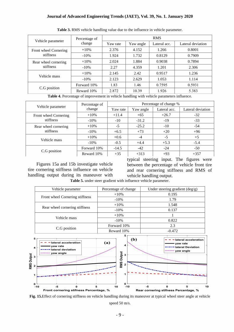
Table 3 presented the RMS value of
vehicle handling indices under typical
steering input during vehicle maneuvering.
These RMS investigate the values of vehicle
output for vehicle parameter influence.
Table 4 presented the percentage of change
in vehicle output forces; this change
investigates the effect of vehicle parameters
on vehicle handling output during its
maneuvers. The change in vehicle handling
output presneted the improvement and the
negative effect of this influence in vehicle
parameters for typical steering input. Table
5 presented the change in under steering
gradient stability for the vehicle model
under this maneuver. This investigates the
effect of vehicle parameters on steering
type, steering gradient change.
Journal of Advanced Engineering Trends (JAET), Vol. 39, No. 1. January 2020
- 9 -
Table 3. RMS vehicle handling value due to the influence in vehicle parameter.
Table 4. Percentage of improvement in vehicle handling with vehicle parameters influence.
Figures 15a and 15b investigate vehicle
tire cornering stiffness influence on vehicle
handling output during its maneuver with
typical steering input. The figures were
between the percentage of vehicle front tire
and rear cornering stiffness and RMS of
vehicle handling output. Table 5. under steer gradient with influence vehicle parameter.
Fig. 15.Effect of cornering stiffness on vehicle handling during its maneuver at typical wheel steer angle at vehicle
speed 50 m/s.
Vehicle parameter Percentage of
change
RMS
Yaw rate Yaw angle Lateral acc. Lateral deviation
Front wheel Cornering
stiffness
+10% 2.376 4.152 1.266 0.8001
-10% 1.924 1.732 0.8129 0.7909
Rear wheel cornering
stiffness
+10% 2.024 1.884 0.9038 0.7894
-10% 2.27 4.359 1.201 2.306
Vehicle mass +10% 2.145 2.42 0.9517 1.236
-10% 2.123 2.629 1.053 1.114
C.G position Forward 10% 3831 38.1 582040 580413
Reward 10% 28322 35814 38421 08131
Vehicle parameter Percentage of
change
Percentage of change %
Yaw rate Yaw angle Lateral acc. Lateral deviation
Front wheel Cornering
stiffness
+10% +11.4 +65 +26.7 -32
-10% -10 -31.2 -19 -33
Rear wheel cornering
stiffness
+10% -5 -25.2 -10 -54
-10% +6.5 +73 +20 +96
Vehicle mass +10% +0.6 -4 -5 +5
-10% -0.5 +4.4 +5.3 -5.4
C.G position Forward 10% -14.5 -42 -24 -50
Reward 10% +35 +313 +93 +357
Vehicle parameter Percentage of change Under steering gradient (deg/g)
Front wheel Cornering stiffness +10% 0.195
-10% 1.79
Rear wheel cornering stiffness +10% 1.548
-10% 0.137
Vehicle mass +10% 1
-10% 0.822
C.G position Forward 10% 2.3
Reward 10% -0.472
Journal of Advanced Engineering Trends (JAET), Vol. 39, No. 1. January 2020
- 10 -
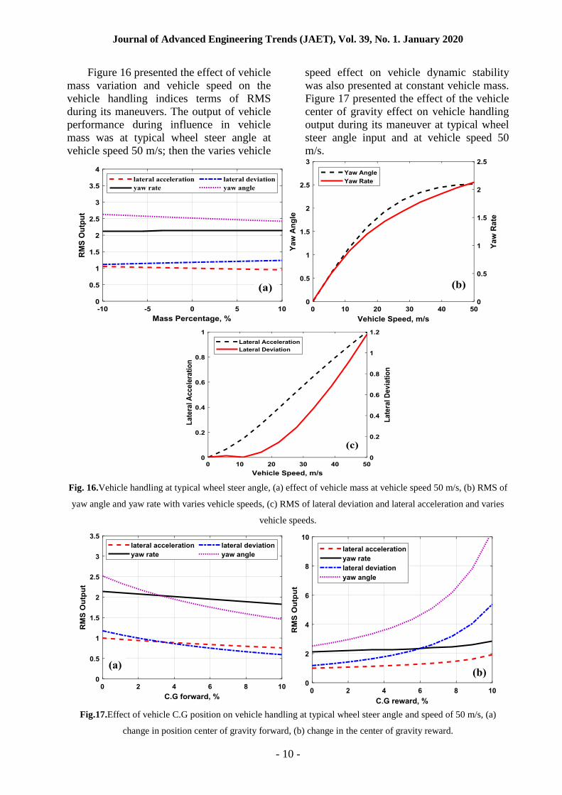
Figure 16 presented the effect of vehicle
mass variation and vehicle speed on the
vehicle handling indices terms of RMS
during its maneuvers. The output of vehicle
performance during influence in vehicle
mass was at typical wheel steer angle at
vehicle speed 50 m/s; then the varies vehicle
speed effect on vehicle dynamic stability
was also presented at constant vehicle mass.
Figure 17 presented the effect of the vehicle
center of gravity effect on vehicle handling
output during its maneuver at typical wheel
steer angle input and at vehicle speed 50
m/s.
Fig. 16.Vehicle handling at typical wheel steer angle, (a) effect of vehicle mass at vehicle speed 50 m/s, (b) RMS of
yaw angle and yaw rate with varies vehicle speeds, (c) RMS of lateral deviation and lateral acceleration and varies
vehicle speeds.
Fig.17.Effect of vehicle C.G position on vehicle handling at typical wheel steer angle and speed of 50 m/s, (a)
change in position center of gravity forward, (b) change in the center of gravity reward.
Journal of Advanced Engineering Trends (JAET), Vol. 39, No. 1. January 2020
- 11 -
5 CONCLUSION
In this paper, complete parametrical and
conflict analyses including the geometrical
and vehicle design parameters were
conducted. During the simulations, a 2-
DOFs bicycle-vehicle model was
implemented and verified using the
MATLAB/Simulink and thereafter two
steering modes (step input and typical steer
angle) were used to examine the sensitivity
of vehicular stability and handling
performances. In this manner, both the yaw
rate and vehicle lateral acceleration were
mainly considered as the vehicle stability
indices.
Given the simulation results, significant
influences on the vehicular stability and
handling indices were observed when the
position of thevehicle center of gravity was
10% shifted either to the forward and
reward. This is related to the change in
vehicle form the under steering zone to the
over steering zone. On the other hand, the
vehicle mass presented a slight effect on
vehicle stability and handling which can be
neglected. Finally, the other remaining
parameters presented fluctuated vehicle
dynamic stability with lower impact on
vehicle under steering gradient.
REFERENCES
[1] MATLAB. The MathWorks. Inc, United States,
patents. 2005.
[2] Ko, Y. and C. Song, Vehicle modeling with
nonlinear tires for vehicle stability analysis.
International Journal of Automotive
Technology, 2010. 11(3): p. 339-344.
[3] Khan, M.M., A.U. Awan, and M.
Liaquat,Improving Vehicle Handling and
Stability under Uncertainties using
Probabilistic Approach. IFAC-PapersOnLine,
2015. 48(25): p. 242-247.
[4] Subramaniyam, K.V., C.N. Kumar, and S.C.
Subramanian, Analysis of Handling
Performance of Hybrid Electric Vehicles.
IFAC-PapersOnLine, 2018. 51(1): p. 190-195.
[5] Kirli, A. and M.S. Arslan, Optimization of
parameters in the hysteresis-based steering feel
model for steer-by-wire systems. IFAC-
PapersOnLine, 2016. 49(3): p. 129-134.
[6] Tavoosi, V., R. Kazemi, and S. Hosseini,
Vehicle handling improvement with steer-by-
wire system using hardware in the loop method.
Journal of applied research and technology,
2014. 12(4): p. 769-781.
[7] Lee, S., K. Nakano, and M. Ohori,
Identification of yaw moment of inertia of a
truck during travelling. IFAC Proceedings
Volumes, 2013. 46(21): p. 768-772.
[8] De Bruyne, S., et al. Online estimation of
vehicle inertial parameters for improving
chassis control systems. in IFAC World
Congress. 2011.
[9] Mazumder, H., et al., Performance analysis of
EV for different mass distributions to ensure
safe handling. Energy Procedia, 2012. 14: p.
949-954.
[10] Lin, C., et al., Estimation of Center of Gravity
Position for Distributed Driving Electric
Vehicles Based on Combined H∞-EKF Method.
Energy Procedia, 2016. 88: p. 970-977.
[11] Wesemeier, D. and R. Isermann, Identification
of vehicle parameters using stationary driving
maneuvers. Control Engineering Practice, 2009.
17(12): p. 1426-1431.
[12] Crolla, D., G. Firth, and D. Horton, An
introduction to vehicle dynamics. 1992:
University of Leeds, Department of Mechanical
Engineering.
[13] Ranganathan, R. and A. Aia, Development of
heavy vehicle dynamic stability analysis model
using MATLAB/SIMULINK. 1995, SAE
Technical Paper.
Journal of Advanced Engineering Trends (JAET), Vol. 39, No. 1. January 2020
- 12 -
دراسة تاثير المعاملات التصميمية على اداء ثبات السيارة
الدين مصطفى سالم ، محمد على حسن مرادمحى ، خالد على عبد الجواد ،مينا مجدى ابراهيم
الملخص:
في ىذه البحث ، يقترح نموذج نصف سيارىو طولى لدراسة ثبات السيارة الديناميكي في اكثر من مناورة لممركبة. تم تطوير
لمتنبؤ بالاستقرار الديناميكي لممركبة في إطار مناورات مختمفة. MATLAB / Simulinkالمحاكاة باستخدام برنامج تطبيق
لمتحقق من ثبات السيارة ، يتم اختيار زاوية عجمة القيادة لتكون مدخلات النموذج الأساسي لإجراءات التحميل. يتم التحقق من
ية عجمة توجيو جديدة لفحص مخرجات صحة النموذج المطور عبر إدخال زاوية توجيو لمسيارة علاوة عمى ذلك ، تم ادخال زاو
yawالسيارة التي يتم التنبؤ بيا عمى الطريق السريع داخل المناورة. يتم اعتماد المخرجات الديناميكية لممركبة ، وىي زاوية ال
مركز لجميع المناورات التي تم فحصيا. لقد وجد أن معاملات تصميم السيارة مثل تغيير وضع lateral acceleration و
( ، وكتمة السيارة ، وصلابة إطار الإطارات وسرعة السيارة ليا تأثير كبير عمى ثبات السيارة الديناميكي. CGثقل السيارة )
التغيير في مركز السيارة من موقف الجاذبية ىو أكثر المعممة لو تأثير في ديناميات استقرار السيارة.