Embed Size (px)
Citation preview
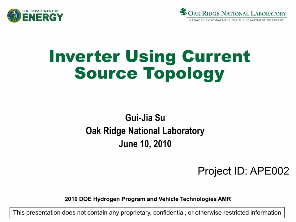
Inverter Using CurrentSource Topology
Gui-Jia SuOak Ridge National Laboratory
June 10, 2010
Project ID: APE002
This presentation does not contain any proprietary, confidential, or otherwise restricted information
2010 DOE Hydrogen Program and Vehicle Technologies AMR
2 Managed by UT-Battellefor the U.S. Department of Energy
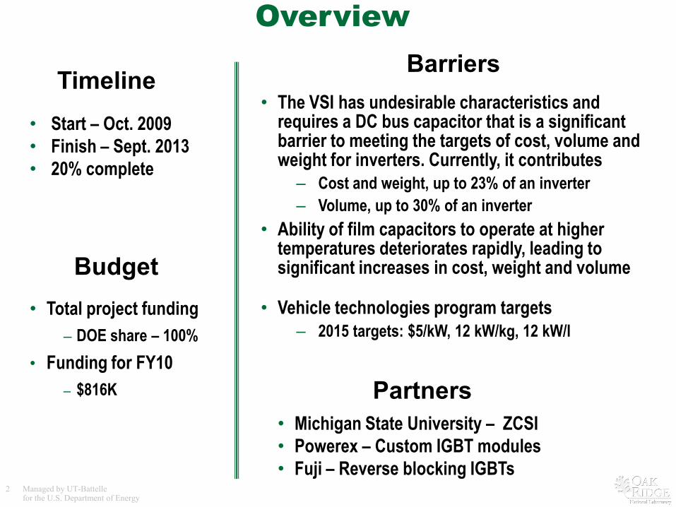
Overview
• Start – Oct. 2009• Finish – Sept. 2013• 20% complete
• The VSI has undesirable characteristics and requires a DC bus capacitor that is a significant barrier to meeting the targets of cost, volume and weight for inverters. Currently, it contributes
– Cost and weight, up to 23% of an inverter– Volume, up to 30% of an inverter
• Ability of film capacitors to operate at higher temperatures deteriorates rapidly, leading to significant increases in cost, weight and volume
• Vehicle technologies program targets– 2015 targets: $5/kW, 12 kW/kg, 12 kW/l
Timeline
Budget
Barriers
Partners• Michigan State University – ZCSI• Powerex – Custom IGBT modules• Fuji – Reverse blocking IGBTs
• Total project funding– DOE share – 100%
• Funding for FY10– $816K
3 Managed by UT-Battellefor the U.S. Department of Energy
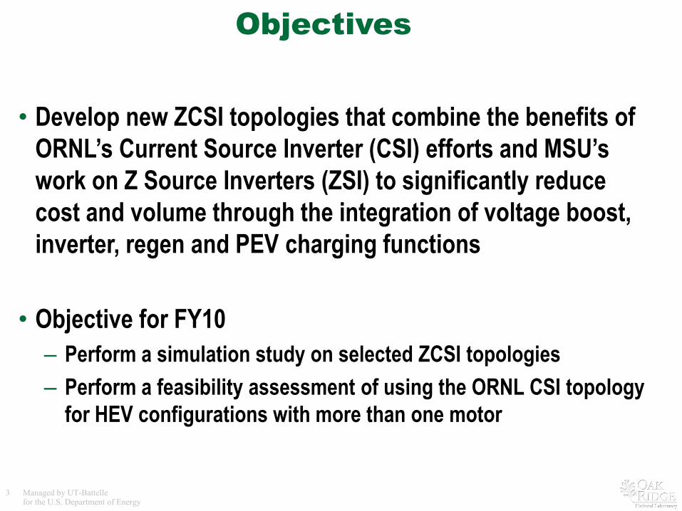
Objectives
• Develop new ZCSI topologies that combine the benefits of ORNL’s Current Source Inverter (CSI) efforts and MSU’s work on Z Source Inverters (ZSI) to significantly reduce cost and volume through the integration of voltage boost, inverter, regen and PEV charging functions
• Objective for FY10– Perform a simulation study on selected ZCSI topologies– Perform a feasibility assessment of using the ORNL CSI topology
for HEV configurations with more than one motor
4 Managed by UT-Battellefor the U.S. Department of Energy
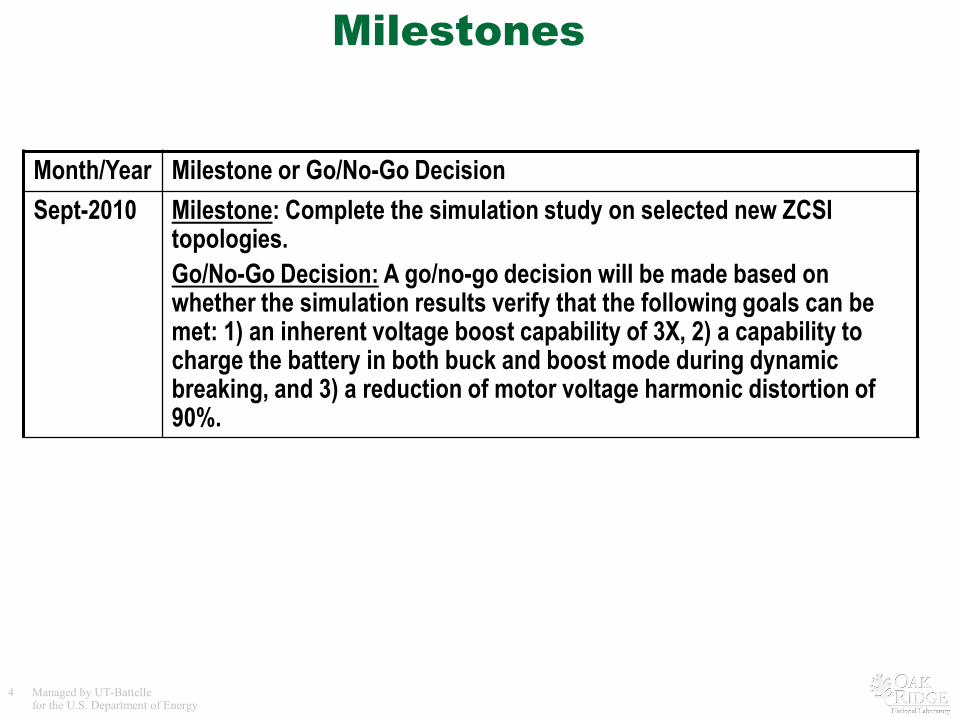
Milestones
Month/Year Milestone or Go/No-Go DecisionSept-2010 Milestone: Complete the simulation study on selected new ZCSI
topologies. Go/No-Go Decision: A go/no-go decision will be made based on whether the simulation results verify that the following goals can be met: 1) an inherent voltage boost capability of 3X, 2) a capability to charge the battery in both buck and boost mode during dynamic breaking, and 3) a reduction of motor voltage harmonic distortion of 90%.
5 Managed by UT-Battellefor the U.S. Department of Energy
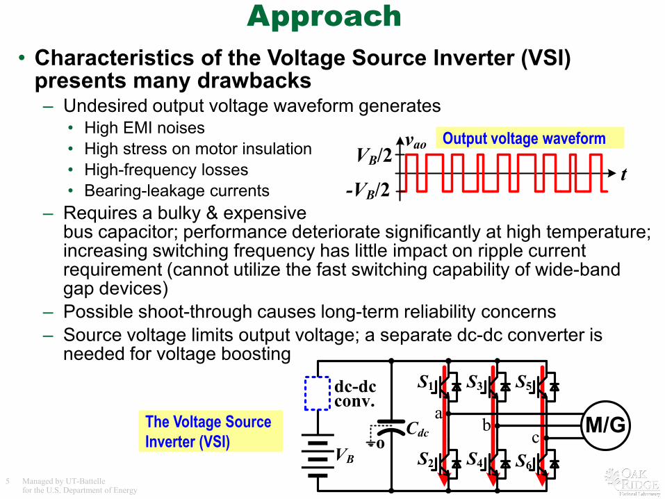
Approach• Characteristics of the Voltage Source Inverter (VSI)
presents many drawbacks– Undesired output voltage waveform generates
• High EMI noises• High stress on motor insulation• High-frequency losses• Bearing-leakage currents
– Requires a bulky & expensive bus capacitor; performance deteriorate significantly at high temperature; increasing switching frequency has little impact on ripple current requirement (cannot utilize the fast switching capability of wide-band gap devices)
– Possible shoot-through causes long-term reliability concerns– Source voltage limits output voltage; a separate dc-dc converter is
needed for voltage boosting
t
vaoVB/2
-VB/2
Output voltage waveform
Cdc
S1
S2
S3
S4
S5
S6
M/Gab
coVB
dc-dcconv.
The Voltage Source Inverter (VSI)
6 Managed by UT-Battellefor the U.S. Department of Energy
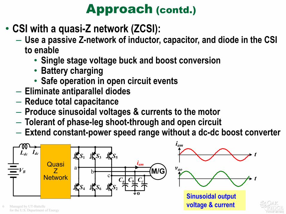
Approach (contd.)
• CSI with a quasi-Z network (ZCSI):– Use a passive Z-network of inductor, capacitor, and diode in the CSI
to enable• Single stage voltage buck and boost conversion• Battery charging• Safe operation in open circuit events
– Eliminate antiparallel diodes– Reduce total capacitance– Produce sinusoidal voltages & currents to the motor– Tolerant of phase-leg shoot-through and open circuit– Extend constant-power speed range without a dc-dc boost converter
Sinusoidal output voltage & current
tiam
tvaoa
b c
Ldc
Ca CcCb
S1
S4
S3
S6
S5
S2
M/GVB
Idc
iam
o
QuasiZ
Network
7 Managed by UT-Battellefor the U.S. Department of Energy
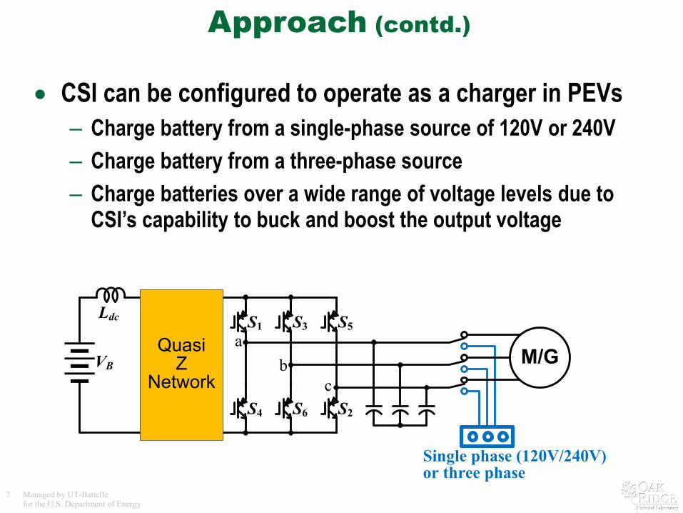
Approach (contd.)
• CSI can be configured to operate as a charger in PEVs– Charge battery from a single-phase source of 120V or 240V– Charge battery from a three-phase source– Charge batteries over a wide range of voltage levels due to
CSI’s capability to buck and boost the output voltage
ab
c
Ldc S1
S4
S3
S6
S5
S2
VB
QuasiZ
NetworkM/G
Single phase (120V/240V)or three phase
8 Managed by UT-Battellefor the U.S. Department of Energy
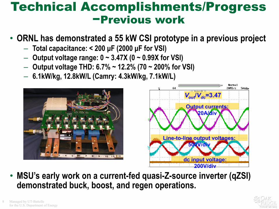
Technical Accomplishments/Progress −Previous work
• ORNL has demonstrated a 55 kW CSI prototype in a previous project– Total capacitance: < 200 μF (2000 μF for VSI)– Output voltage range: 0 ~ 3.47X (0 ~ 0.99X for VSI)– Output voltage THD: 6.7% ~ 12.2% (70 ~ 200% for VSI) – 6.1kW/kg, 12.8kW/L (Camry: 4.3kW/kg, 7.1kW/L)
• MSU’s early work on a current-fed quasi-Z-source inverter (qZSI) demonstrated buck, boost, and regen operations.
Output currents: 20A/div
Line-to-line output voltages: 500V/div
dc input voltage: 200V/div
Vout/Vdc=3.47
9 Managed by UT-Battellefor the U.S. Department of Energy
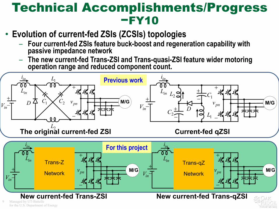
Technical Accomplishments/Progress−FY10
• Evolution of current-fed ZSIs (ZCSIs) topologies – Four current-fed ZSIs feature buck-boost and regeneration capability with
passive impedance network– The new current-fed Trans-ZSI and Trans-quasi-ZSI feature wider motoring
operation range and reduced component count.
Current-fed qZSI
New current-fed Trans-qZSINew current-fed Trans-ZSI
The original current-fed ZSI
+
+
−
−
inV
inL
pnv
ini
M/GD 1C 2C
1L
2L
+
−+
+
−
−
inV D
inL1C
pnv
ini
2L
1L2C
−+
M/G
+
−+−inV
D
inL
1
ini
2
1L
1Li2Li +
−
pnv M/GTrans-qZ
Network+
−
+
−inV
inL
1CD
ini
2L1L +
−
pnv M/GTrans-Z
Network
Previous work
For this project
10 Managed by UT-Battellefor the U.S. Department of Energy
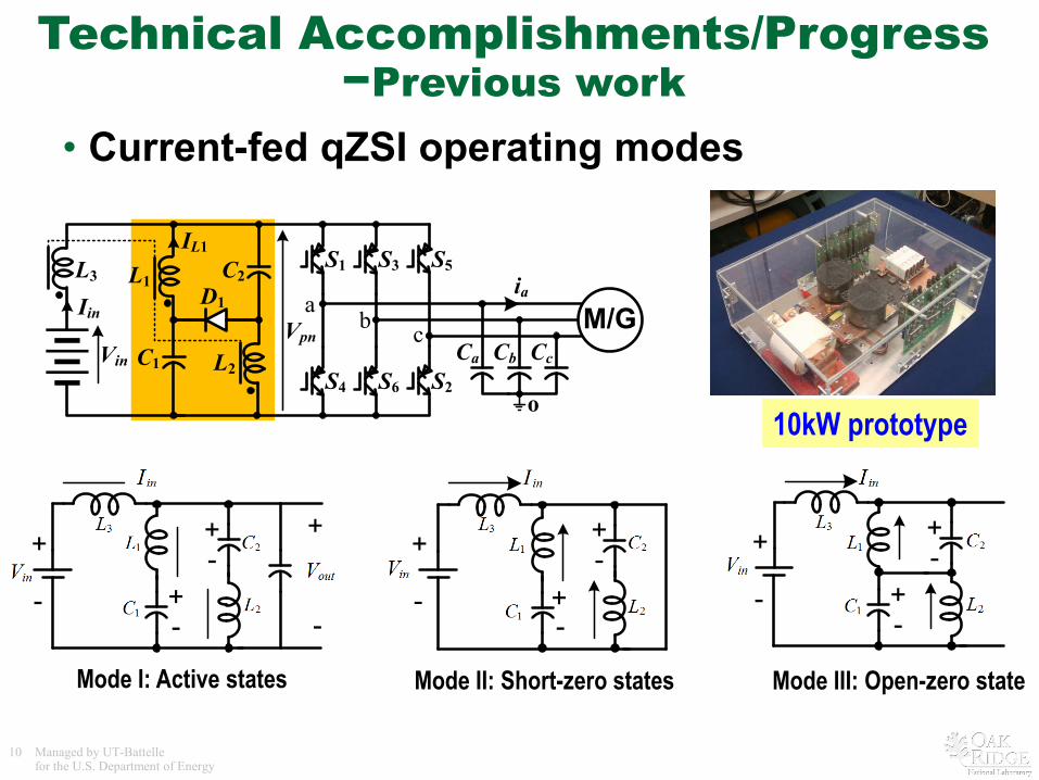
Technical Accomplishments/Progress−Previous work
• Current-fed qZSI operating modes
ab c
L3
Ca CcCb
S1
S4
S3
S6
S5
S2
M/GVin
Iinia
o
C2
C1
L1
L2
D1
IL1
Vpn
+
-
+
-
+-
+-
-
+
+
+-
--
+
+-
+-
Mode I: Active states Mode II: Short-zero states Mode III: Open-zero state
10kW prototype
11 Managed by UT-Battellefor the U.S. Department of Energy
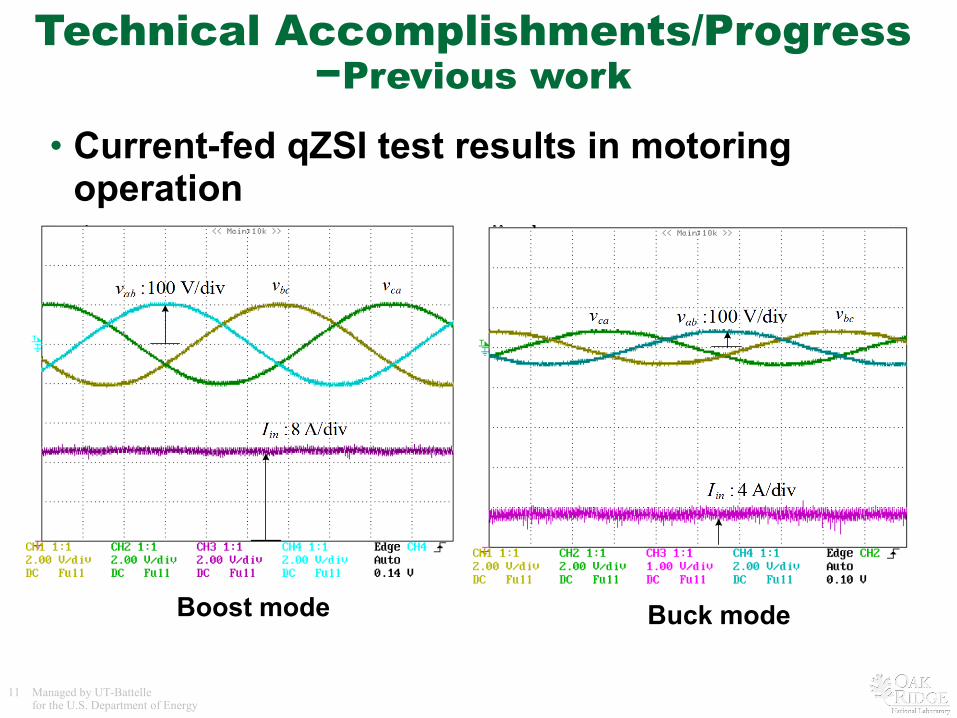
Technical Accomplishments/Progress−Previous work
• Current-fed qZSI test results in motoring operation
Boost mode Buck mode
12 Managed by UT-Battellefor the U.S. Department of Energy
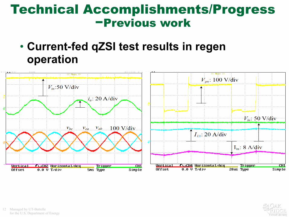
Technical Accomplishments/Progress−Previous work
• Current-fed qZSI test results in regen operation
13 Managed by UT-Battellefor the U.S. Department of Energy
0.2 0.4 0.6 0.8 1-3
-2
-1
0
1
2
3
eq
in
VV
AActive duty ratio D
Motoring range
Regenerationrange
0.2 0.4 0.6 0.8 1-4
-3
-2
-1
0
1
2
3
4
eq
in
VV
AActive duty ratio D
Motoring range
Regenerationrange
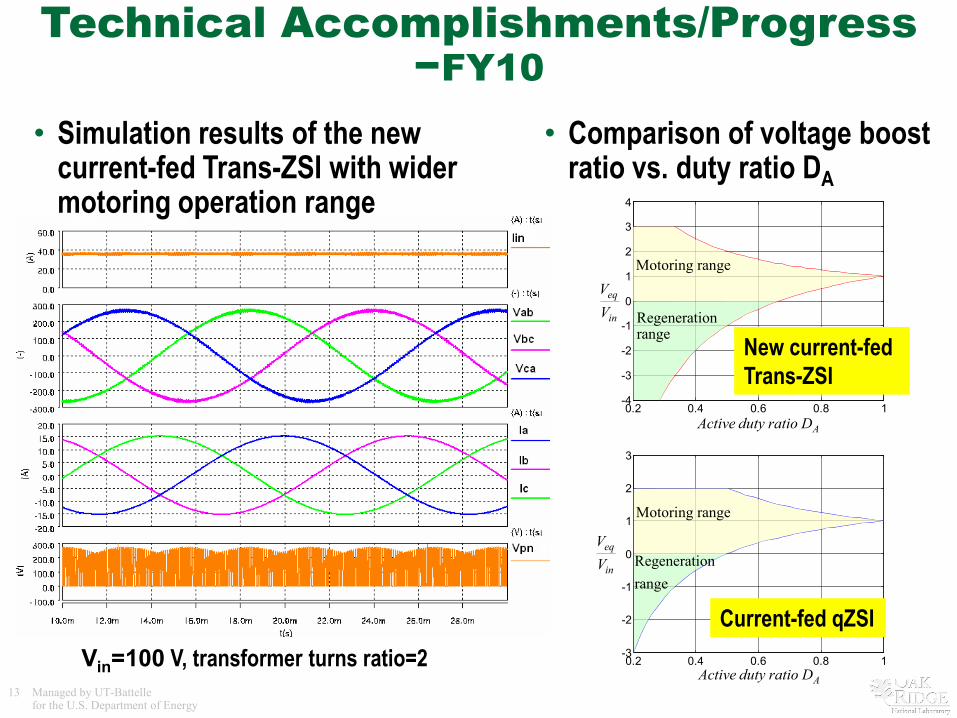
Technical Accomplishments/Progress−FY10
• Simulation results of the new current-fed Trans-ZSI with wider motoring operation range
Vin=100 V, transformer turns ratio=2
• Comparison of voltage boost ratio vs. duty ratio DA
New current-fed Trans-ZSI
Current-fed qZSI
14 Managed by UT-Battellefor the U.S. Department of Energy
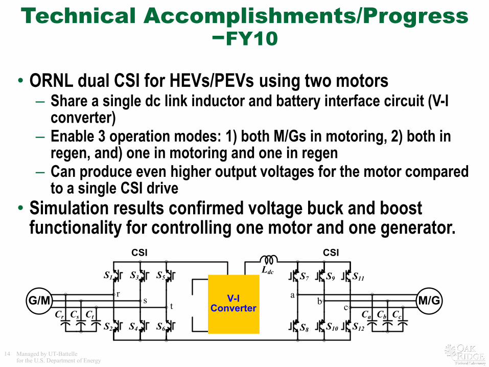
Technical Accomplishments/Progress−FY10
• ORNL dual CSI for HEVs/PEVs using two motors– Share a single dc link inductor and battery interface circuit (V-I
converter)– Enable 3 operation modes: 1) both M/Gs in motoring, 2) both in
regen, and) one in motoring and one in regen– Can produce even higher output voltages for the motor compared
to a single CSI drive• Simulation results confirmed voltage buck and boost
functionality for controlling one motor and one generator.CSI
ab c
Ldc
Ca CcCb
S7
S8
S9
S10
S11
S12
rs t
Cr CtCs
S4 S6
S3 S5
S2
S1
G/M M/G
CSI
V-I Converter
15 Managed by UT-Battellefor the U.S. Department of Energy
Collaborations
• Michigan State University (academic) – collaborations on current-fed Z-source inverter (ZCSI) topologies
• Powerex (industry) – collaborations on design and fabrication of custom IGBT modules for prototype development
• Fuji Semiconductor (industry) – collaborations about latest development in reverse blocking IGBTs and its impact on CSIs
16 Managed by UT-Battellefor the U.S. Department of Energy
Future Work • Remainder of FY10
– Complete the simulation study of the two new ZCSI topologies– Complete the feasibility assessment of the dual CSI for HEVs/PEVs
using two motors
• FY11– Design, fabricate, and test two 55 kW prototypes based on the two new
ZCSI topologies
• FY12– Perform feasibility study of the new ZCSIs for PEV configurations using
more than one motor– Design and fabricate 55 kW prototypes based on the new ZCSI
topologies for PEV configurations using more than one motor
• FY13– Test and characterize the 55 kW ZCSI prototypes built in FY12 in
traction drive and battery charger modes
17 Managed by UT-Battellefor the U.S. Department of Energy
Summary
• The ZCSI inverters use passive components to enable the CSI to – buck and boost output voltage in a single stage conversion– operate in regen mode to charge the battery– operate safely in open and short circuit events– operate as a universal charger for PHEVs
• Reduce power electronics cost, weight and volume• Increase constant-power speed range without using a dc-dc boost
converter• Improve inverter reliability and motor lifetime and efficiency• Provide design flexibility in sizing the battery
• Prototype test results from previous work and simulation study indicate the ZCSI is a promising alternative to the VSI and can fully utilize the fast switching wide-band gap devices to significantly reduce the size, weight and volume of the passive components.

![A Review of Multilevel Inverter Topology and Control ... Review of Multilevel Inverter Topology and Control Techniques . ... dv/dt) [1], multilevel inverter has ... configuration has](https://img.pdfslide.us/doc/110x75/5ae02cdf7f8b9a6e5c8d10cd/a-review-of-multilevel-inverter-topology-and-control-review-of-multilevel-inverter.jpg)


![[1991]a General Circuit Topology of Multilevel Inverter](https://img.pdfslide.us/doc/110x75/577cc9241a28aba711a376be/1991a-general-circuit-topology-of-multilevel-inverter.jpg)