Embed Size (px)
Citation preview
INVERTER
USER MANUAL
SERIES L-UPSSERIES SW-LUPS
SINE WAVE AND STEP WAVEDigital Long Backup UPS
High Current Battery Charger
Jan. 2013.UMSIV-Ver.10
- 2 -
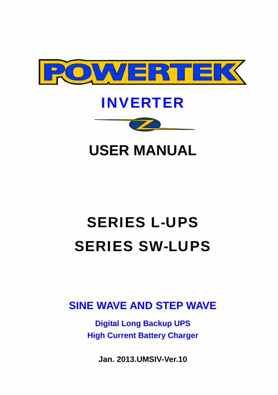
L-UPS-3600, L-UPS-4000 AND SW-UPS-3000
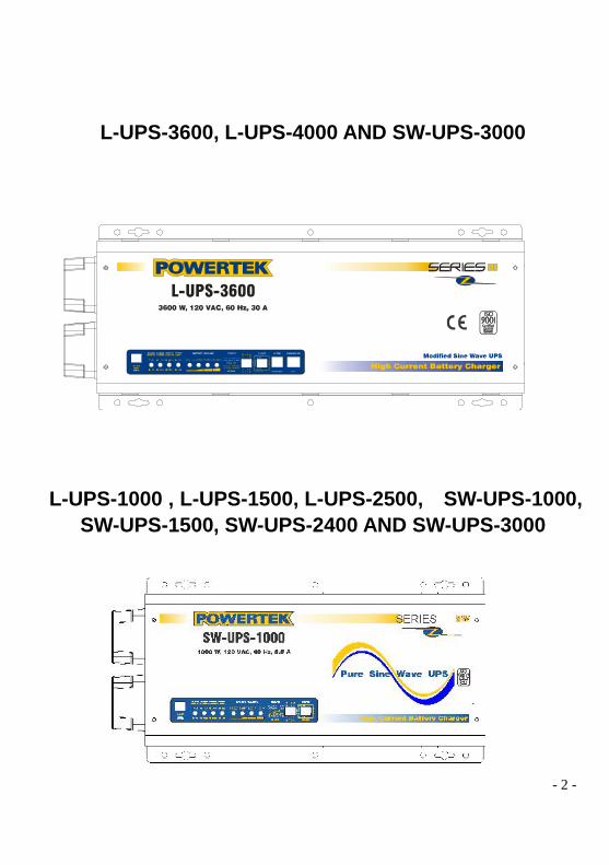
L-UPS-1000 , L-UPS-1500, L-UPS-2500, SW-UPS-1000,SW-UPS-1500, SW-UPS-2400 AND SW-UPS-3000
- 3 -
TABLE OF CONTENTS
1. Introduction 6
1.1 Introduction 6
1.2 Important Safety Instructions 7
1.2.1 General Precautions 7
1.2.2 Personal Precautions 8
2. Front Panel / Inverter Operation 8
2.1 Indicators and Settings 8
2.1.1 Controls and LED Indicators 8
2.1.2 Power ON-OFF- RESET Push Button 9
2.1.3 Inverter DC Mode LED (LED1) 9
2.1.4 AC Mode / Battery Charger LED (LED2) 9
2.1.5 Limited Conditions Over Temperature / Overload LED (LED 3) 9
2.1.6 Battery High / Low LED (LED 4) 10
2.1.7 Battery Voltage Meter LED (LED 5-8) 11
2.1.8 LED and Alarm Indicator 12
2.1.9 Feature Settings 13
2.1.9.1 DC to AC Transfer Delay Setting (Switch 1) 13
2.1.9.2 Low Battery Warning Setting (Switch 2) 13
2.1.9.3 AC Transfer Voltage Setting (Switch 3) 14
2.1.9.4 Search Load Mode Setting (Switch 4) 14
2.1.10 Charger Settings 15
2.1.10.1 Charging Profile / Floating Voltage Setting (Switch 5) 15
2.1.10.2 Batter Charging Rate Setting (Switch 6,7,8) 15
- 4 -
3. Battery 16
3.1 Battery Size 16
3.1.1 Estimating Battery Requirement 16
3.2 Battery Maintenance 17
3.3 Battery Configurations 19
3.3.1 Parallel Connection 19
3.3.2 Series Connection 19
3.3.3 Series-Parallel Connection 20
3.4 Battery Installation 20
3.4.1 Battery Location 20
3.4.2 Battery Enclosure 20
3.4.3 Battery Cables 21
4. Installation 22
4.1 Inverter Installation 22
4.1.1 Environment 22
4.1.2 System Grounding 22
4.1.2.1 Equipment or Chassis Grounds 23
4.1.2.2 Ground Electrodes / Ground Rods 23
4.1.3 Bonding the Grounding System to the Neutral
and Negative Conductors 23
4.2 Installation Diagrams 24
4.2.1 DC Wire Size. 24
4.2.2 Terminal Block AC Side. 26
4.2.3 AC Wire Gauge recommended 26
4.2.4 Simple Installation Diagram. 26
4.2.5 General Installation Diagram. 27
- 5 -
4.3 Connection’s Steps (Simple Installation Diagram) 28
4.3.1 Step 1 “Connect the inverter and Test the Battery Mode”. 28
4.3.2 Step 2 “Connect the inverter to an AC Source”. 28
4.3.3 Step 3 “Turn the inverter ON”. 28
4.3.4 Step 4 “Connect the Load”. 29
4.3.5 Step 5 “Transfer the Load to the AC Input Source”. 29
5. Technical Specifications5.1 SERIES L-UPS 30
5.2 SERIES SW-UPS 31
6. Service and Support 32
7. POWERTEK Warranty 33
8. Troubleshooting 34
9. Technical information Disclaimer 35
10. Technical Note: CHARGING AGM BATTERIES 36
- 6 -
1. Introduction1.1 Introduction
These units are powerful inverter / charger systems made up of three modules: inverter,
charger and transfer switch.
The POWERTEK INVERTER Series L-UPS and SW are a heavy-duty, continuous working
System generating a modified sine wave from a 12V/24V - battery bank. It can supply energy
to various loads including resistive loads (heater), inductive loads (air conditioners, refrigerator),
motors (vacuum cleaners), and rectifier loads (computer).
For example, a single Powertek model L-UPS-3524 with a 880 AH battery bank can supply a
2000W workload for over 8 hours after a charge of 10 hours.
All Powertek models are designed to work under heavy load conditions.
The smart charger can be set with different charging profiles to match battery banks of different
capacities. The high power charger can charge a 24V/800 AH battery bank in 10 hours.
The transfer switch module automatically diverts the energy transfer path between inverter and
utility source. When the utility source is lower or higher than the transfer voltage levels, the
path switches to the inverter. Otherwise the load is conducted to the utility source. The
Powertek Inverter has an extremely fast transfer time, the time it takes to detect an abnormal
input voltage plus the time to switch the load from the AC input source to the inverter’s output.
The POWERTEK INVERTER is an extremely good choice for utility back up power and the
rapid transfer time makes it possible to be used as a UPS for computers.

- 7 -
1.2 Important Safety Instructions
1.2.1 General Precautions
1. Before using the INVERTER, please read all instructions and warnings in this manual.
2. Do not expose the INVERTER to rain, snow, or liquids of any type. The INVERTER is
designed for indoor mounting only. Protect the inverter from splashing if used in vehicle
applications.
3. Take the INVERTER to a qualified service center when service or maintenance is required.
Incorrect re-assembly may result in risk of electric shock or fire.
4. Reduce the risk of electric shock by disconnecting all wiring before making any attempt to
maintain or clean the unit. Simply turning off the INVERTER will not reduce this risk.
5. Systems installed with photovoltaic cells or wind generators will produce power when
exposed to light or wind. Be sure to disconnect these power sources before maintenance.
6. WORKING IN THE VICINITY OF A LEAD ACID BATTERY IS DANGEROUS.BATTERIES GENERATE EXPLOSIVE GASES DURING NORMAL OPERATION. The
battery compartment should be well ventilated. The battery enclosure should be designed to
prevent accumulation and concentration of hydrogen gas "pockets" at the top of the
compartment. Vent the battery compartment from the highest point. A sloped lid can also be
used to direct the flow through the vent opening location.
7. HYDROGEN ACCUMULATION MAY CAUSE BATTERIES TO EXPLODE.
8. REVERSING BATTERY BANK POLARITY MAY CAUSE SERIOUS DAMAGES NOTCOVERED BY THE WARRANTY.9. CONNECTING AN AC SOURCE TO THE INVERTER AC OUTPUT MAY CAUSEDAMAGES NOT COVERED BY THE WARRANTY10. NEVER try to recharge a frozen battery.
11. Torque all AC wiring connections to 15-20 inch-pounds.
12. Torque all DC cable connections to 10-12 foot-pounds.
13. Be extremely cautious when working with metal tools around batteries. Dropping a tool
could cause a short circuit or produce sparks that could cause an explosion.
14. The INVERTER must be used with a battery supply that matches the nominal DC :
15. GROUNDING INSTRUCTIONS. This inverter / charger should be connected to a grounded,
permanent wiring system. For most installations, the negative battery conductor should be
bonded to the grounding system at one, and only one, point in the system. All installations
should comply with all national and local codes and ordinances.
- 8 -
1.2.2 Personal Precautions1. Someone should be within voice range when you work near batteries in case of an
emergency.
2. Have plenty of fresh water and soap nearby in case battery acid contacts skin, clothing, or
eyes.
3. Wear complete eye and clothing protection. Avoid touching eyes while working near
batteries. Wash your hands when done.
4. If battery acid contacts skin or clothing, immediately wash with soap. If acid enters eyes
immediately flood eyes with cold running water for at least 15 minutes. Seek medical attention.
5. Never smoke or allow a spark or flame in the vicinity of a battery or generator.
6. Remove personal metal items such as rings, bracelets, necklaces, and watches when
working with batteries. A battery can produce a short -circuit current, which is high enough to
weld a ring to a battery terminal.
2. Front Panel / Inverter Operation
2.1 Indicator and Settings2.1.1 Controls and LED Indicators
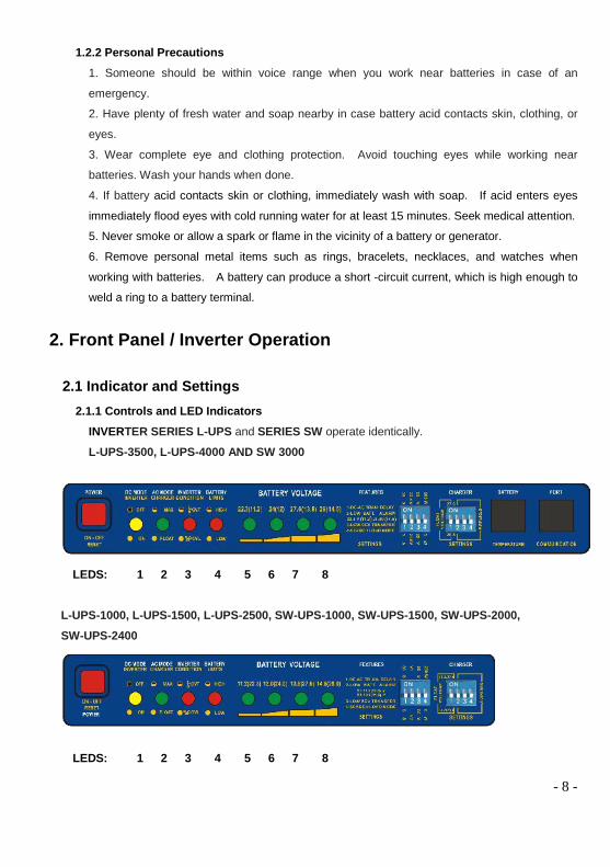
INVERTER SERIES L-UPS and SERIES SW operate identically.
L-UPS-3500, L-UPS-4000 AND SW 3000
LEDS: 1 2 3 4 5 6 7 8
L-UPS-1000, L-UPS-1500, L-UPS-2500, SW-UPS-1000, SW-UPS-1500, SW-UPS-2000,SW-UPS-2400
LEDS: 1 2 3 4 5 6 7 8
- 9 -
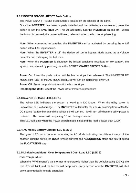
2.1.2 POWER ON-OFF - RESET Push ButtonThe Power ON/OFF-RESET push button is located on the left side of the panel.
Once the INVERTER has been properly installed and the batteries are connected, press the
button to turn the INVERTER ON. This will alternately turn the INVERTER on and off. When
the button is pressed, the buzzer will beep, release it when the buzzer stop beeping.
Note: When connected to batteries, the INVERTER can be activated by pressing the on/off
button without AC input source.
Note: When the INVERTER is off, the device will be in Bypass Mode acting as a Voltage
protector and recharging the batteries.
Note: When the INVERTER is shutdown by limited conditions (overload or low battery), the
system can be reset by pressing twice the POWER ON-OFF / RESET Button.
Power On: Press the push button until the buzzer stops then release it. The INVERTER DC
MODE light (LD1) or the AC MODE led (LD2) will turn on indicating Power On.
Power Off: Press the push button until the buzzer stops
Resetting the Unit: Repeat the Power Off or Power On procedure
2.1.3 Inverter DC Mode LED (LED 1)The yellow LED indicates the system is working in DC Mode. When the utility power is
unavailable or is out of range. The INVERTER will transfer the energy sourcing from AC to the
DC source (battery bank) and the yellow led will turn on. It will turn off when the utility power is
restored. The buzzer will beep every 10 sec during a minute.
This LED will blink when the Power search mode is set and the load is lower than 220W.
2.1.4 AC Mode / Battery Charger LED (LED 2)The green LED turns on when operating in AC Mode indicating the different steps of the
charger: Blinking during the BULK (limited current) and ABSORBTION steps and fully lit during
the FLOATATION step.
2.1.5 Limited conditions: Over Temperature / Over Load LED (LED 3)Over TemperatureWhen the PWM inverter’s transformer temperature is higher than the default setting 120 oC), the
red LED will blink and the buzzer will beep twice every second and the INVERTER will shut
down automatically for safe operation.

- 10 -
The inverter will restart automatically when the temperature returns to normal.
Over LoadWhen the load surpasses the nominal power in DC mode the red LED 3 will start to blink and
the buzzer will beep every second. If the load is not decreased the inverter will shut off in one
minute and the red led will lit.
If the load surpasses the Maximum power allowed (150 %), the inverter will stop immediately
and LED 3 will be fully lit.
The inverter can be restarted or turned on with the Power ON/OFF / RESET button once the
user has removed the overload condition.
If the AC input comes back on within the acceptable range the unit will transfer the load to the
input source, the LED 3 will turn off. But if the overload condition persists, the AC Input
breaker will trip and the Inverter will switch back to DC mode and the overload condition will
return.
Please refer to the following chart for Overload indicator descriptions.
2.1.6 BATTERY High / Low LED (LED 4)
Battery High:
When batteries reach the high warning voltage of 30V/ 15V in AC mode, the red LED 4 will blink.
The alarm will beep twice every second and the INVERTER will switch to DC mode. The red led
will stay blinking to signalize the high battery condition.
If the batteries reach 30.5V/15.5 Volts in DC mode, the unit will shut off.
CALL INMEDIATELY THE AUTHORIZED SERVICING PERSONAL.
L E D 3
O v e r lo a d
< 1 0 0 % O ff O ff
I N V E R T E R iso p e r a t i n g in D C
M o d e
> 1 0 0 % < 1 5 0 % O nB e e p s e v e ry
s e c .
I N V E R T E R w il ls h u t d o w n in 1
m i n u t e
> M a x P o w e r O n O nI N V E R T E R w il l s h u t
O ff i m m e d ia t e ly
L o a d C a p a c i t y ( D C M o d e ) B u z z e r IN V E R T E RS t a t u s

- 11 -
Battery Low:
In DC Mode when batteries reach low warning voltage, the led will light up and the buzzer will
beep once every second until the battery reaches the low voltage cut off level, and the inverter
shuts down. The inverter can be restarted in DC mode (from low battery condition) by pressing
the Power ON-OFF RESET button.
During this condition the inverter will be waiting for the AC input to restart automatically. If the
battery becomes too discharged (20V) the inverter will SHUT OFF automatically and user
intervention will be necessary to turn the unit ON with the Power On switch.
In AC mode the led will be off while the unit recharges the battery.
.
2.1.7 Battery Voltage Meter LED (LED 5-8)
The LED 5~8 indicates the battery voltage level. Please refer to the details as below.
Battery Voltage LED 5 LED 6 LED 7 LED 810.8V~11.5V / 21.6V~23.0V On X X X11.5V~12.5V / 23.0V~25.0V On On X X12.5V~14.0V / 25.0V~28.0V On On On X14.0V~15.0V / 28.0V~30.0V On On On On
- 12 -
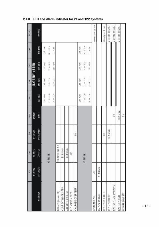
2.1.8 LED and Alarm Indicator for 24 and 12V systems
LED1
LED2
LED3
LED4
LED
5LE
D6
LED
7LE
D8
BUZZ
ER
DCMO
DEAC
MODE
OVER
TEMP
BATT
ERY
COND
ITION
(INVE
RTER
)CH
ARGE
ROV
ERLO
ADED
LIMITS
22.3
(11,2)
24.0
(12.0)
26,8
(13.3)
29.0
(14.5)
WARN
ING
Litif
VBAT
Litif
VBAT
Litif
VBAT
Litif
VBAT
21.6
~23.0
v23
.0~2
5.0v
25.0
~28.0
v28
.0~3
0.0v
10.8
~11.5
v11
.5~1
2.5v
12.5
~14v
14~1
5v
BYPA
SS(P
ower
Off)
ONOR
BLIN
KING
CURR
ENTM
ODE
STEP
BLIN
KING
ABSO
RPTIO
NST
EPBL
INKI
NGFL
OATA
TION
STEP
ONCH
ARGE
ROV
ERTE
MPON
Litif
VBAT
Litif
VBAT
Litif
VBAT
Litif
VBAT
21.6
~23.0
v23
.0~2
5.0v
25.0
~28.0
v28
.0~3
0.0v
10.8
~11.5
v11
.5~1
2.5v
12.5
~14v
14~1
5v
INVE
RTER
ONON
1Bee
p/10
sec.
@1m
in.
NV.S
EARC
HING
BLIN
KING
INV.
OVER
LOAD
EDON
1Bee
pbyS
ec.@
1min.
INV.
OVER
TEMP
BLIN
KING
2Bee
psby
Sec.
BATT
ERY
LOW
WARN
ING
ON2B
eeps
bySe
c.
BATT
ERY
HIGH
BLIN
KING
2Bee
psby
Sec.
INV.O
FFLO
WBA
TON
ACMO
DE
BATT
ERY
METE
R
DCMO
DE
- 13 -
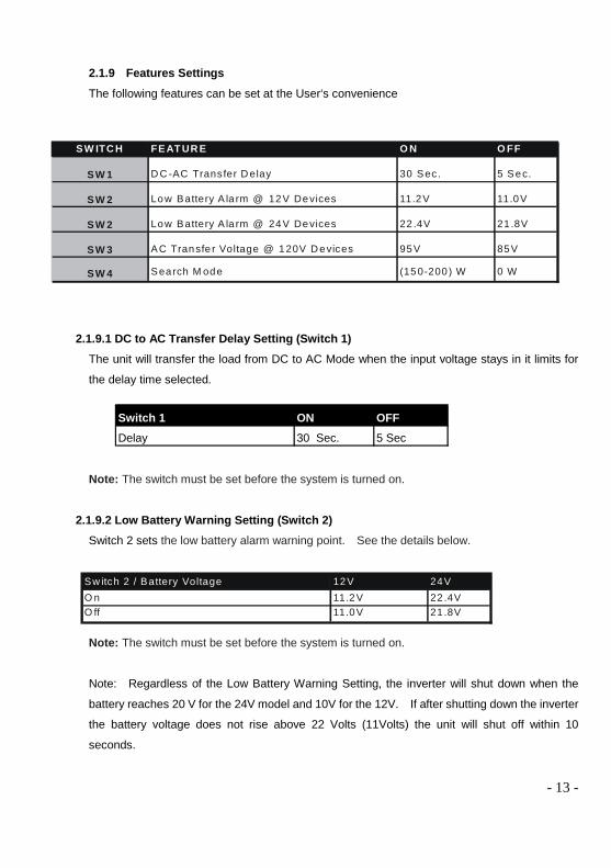
2.1.9 Features SettingsThe following features can be set at the User‘s convenience
2.1.9.1 DC to AC Transfer Delay Setting (Switch 1)The unit will transfer the load from DC to AC Mode when the input voltage stays in it limits for
the delay time selected.
Note: The switch must be set before the system is turned on.
2.1.9.2 Low Battery Warning Setting (Switch 2)Switch 2 sets the low battery alarm warning point. See the details below.
Note: The switch must be set before the system is turned on.
Note: Regardless of the Low Battery Warning Setting, the inverter will shut down when the
battery reaches 20 V for the 24V model and 10V for the 12V. If after shutting down the inverter
the battery voltage does not rise above 22 Volts (11Volts) the unit will shut off within 10
seconds.
Switch 1 ON OFFDelay 30 Sec. 5 Sec
SW ITC H FEAT UR E O N O FF
SW 1 D C -AC Transfer D elay 30 Sec. 5 Sec.
SW 2 Low Battery A la rm @ 12V Devices 11.2V 11.0V
SW 2 Low Battery A la rm @ 24V Devices 22 .4V 21 .8V
SW 3 AC Transfe r Voltage @ 120V D evices 95V 85V
SW 4 Search M ode (150-200 ) W 0 W
Sw itch 2 / Battery Voltage 12V 24VO n 11.2V 22 .4VO ff 11.0V 21 .8V

- 14 -
2.1.9.3 AC Transfer Voltage Setting (Switch 3)Low Voltage Transfer:This switch selects the lower limit of the input voltage to transfer from AC to DC Mode. For
example, when the voltage is lower than 85V, the INVERTER will switch to INVERTER MODE,
where it remains until the voltage reaches 90V. Then the INVERTER, after the delay time
selected with Switch 1, transfers back automatically from DC to AC MODE.
High Voltage Transfer:When the AC input voltage is higher than the default setting, the INVERTER will switch to
DC Mode. If the AC input voltage decreases below the return voltage point, the INVERTER will
automatically switch to AC MODE. Please see the details below.
2.1.9.4 Search Load Mode Setting (Switch 4)
In DC Mode the Inverter can perform a Search load if Switch 4 is set to ON.
A minimum load of 220 W must be present in order to make the inverter start.
Nominal Voltage Transfer (AC toDC)
Return (DC toAC)
120V 135 133220V 264 254230V 276 266
Switch 4 / Search load Mode ON OFFSearch ON Search OFF
Sw itch 3 Low A C Voltage Transfer. 120V 220V 230V
O ff 85 /90V 160/165V 170/175V
O n 95 /100V 190/195V 200/205V
- 15 -
Note: The switch must be set before the system is turned on.
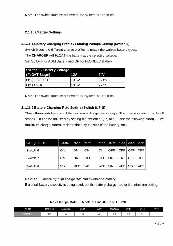
2.1.10 Charger Settings
2.1.10.1 Battery Charging Profile / Floating Voltage Setting (Switch 5)Switch 5 sets the different charge profiles to match the various battery types.
The CHARGER will FLOAT the battery at the selected voltage.
Set S1 OFF for AGM Battery and ON for FLOODED Battery
Note: The switch must be set before the system is turned on.
2.1.10.2 Battery Charging Rate Setting (Switch 6, 7, 8)These three switches control the maximum charge rate in amps. The charge rate in amps has 8
stages. It can be adjusted by setting the switches 6, 7, and 8 (see the following chart). The
maximum charge current is determined by the size of the battery bank.
Charge Rate 100% 80% 60% 50% 40% 30% 20% 10%
Switch 6 ON ON ON ON OFF OFF OFF OFF
Switch 7 ON ON OFF OFF ON ON OFF OFF
Switch 8 ON OFF ON OFF ON OFF ON OFF
Caution: Excessively high charge rate can overheat a battery.
If a small battery capacity is being used, set the battery charge rate to the minimum setting.
Max Charge Rate . Models: SW-UPS and L-UPS
Model 1000@12 1500@12 1500 2000 2400/2500 3024 3624 4024
AmpsMax. 50 50 40 50 50 60 60 70
Switch 5 / Battery Voltage(FLOAT Stage) 12V 24VOn (FLOODED) 13.8V 27.6VOff (AGM) 13.6V 27.2V
- 16 -
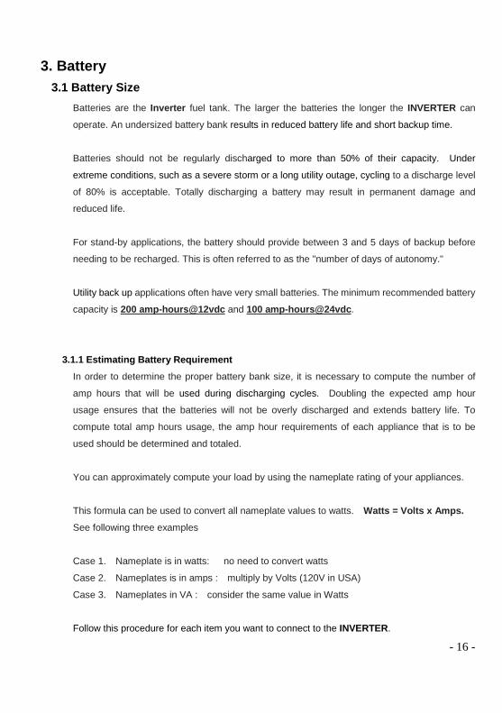
3. Battery3.1 Battery Size
Batteries are the Inverter fuel tank. The larger the batteries the longer the INVERTER can
operate. An undersized battery bank results in reduced battery life and short backup time.
Batteries should not be regularly discharged to more than 50% of their capacity. Under
extreme conditions, such as a severe storm or a long utility outage, cycling to a discharge level
of 80% is acceptable. Totally discharging a battery may result in permanent damage and
reduced life.
For stand-by applications, the battery should provide between 3 and 5 days of backup before
needing to be recharged. This is often referred to as the "number of days of autonomy."
Utility back up applications often have very small batteries. The minimum recommended battery
capacity is 200 amp-hours@12vdc and 100 amp-hours@24vdc.
3.1.1 Estimating Battery RequirementIn order to determine the proper battery bank size, it is necessary to compute the number of
amp hours that will be used during discharging cycles. Doubling the expected amp hour
usage ensures that the batteries will not be overly discharged and extends battery life. To
compute total amp hours usage, the amp hour requirements of each appliance that is to be
used should be determined and totaled.
You can approximately compute your load by using the nameplate rating of your appliances.
This formula can be used to convert all nameplate values to watts. Watts = Volts x Amps.See following three examples
Case 1. Nameplate is in watts: no need to convert watts
Case 2. Nameplates is in amps : multiply by Volts (120V in USA)
Case 3. Nameplates in VA : consider the same value in Watts
Follow this procedure for each item you want to connect to the INVERTER.

- 17 -
Divide the total wattage of your load by the battery voltage to determine the amperage the load
will draw from the batteries
Add the resulting amp hour requirements for each load to determine the total amps hours
requirement.
For example, if the total load is 600Watts the current withdraw from the 24V battery bank will be
approximately 600/24= 25Amps.
Multiplying the DC Amps by the number of hours that the load will be operating you will have a
reasonable estimation of the amps hour.
In this example, if you want 4 hours of backup time multiply 25 amps x 4 hours = 100 amp /
hour.
Now double the amp / hour calculated. This is the requirement for your battery bank.
In this example, it would be a 200 Amp / hour battery bank.
Doubling the amp/hour, will allow the battery to be cycled at 50% on a regular basis.
Motors are normally marked with their running current rather than their starting current. Starting
currents may be three to six times running currents. Manufacturer's literature may provide more
accurate information than the motor nameplate. For larger motors, the battery size must be
increased due to the high demand of start-ups of the motors.
3.2 Battery Maintenance.Check the level of the electrolyte of each battery cell at least once a month.
Always use extreme caution when handling batteries and electrolyte. Wear gloves, goggles and
old clothes. "Battery acid” will burn skin and eyes and destroy cotton and wool clothing.
The quickest way to ruin lead-acid batteries is to discharge them deeply and leave them stand
"dead" for an extended period of time. When they discharge, there is a chemical change in the
positive plates of the battery. They change from lead oxide when charged to lead sulfate when
discharged. If they remain in the lead sulfate state for a few days, some parts of the plate do not
return to lead oxide when the battery is recharged. If the battery remains discharged longer, a
greater amount of the positive plate will remain lead sulfate. The parts of the plates that become
"sulfated" no longer store energy. Batteries that are deeply discharged, and then charged
partially on a regular basis can fail in less than one year.

- 18 -
Check your batteries on a regular basis to be sure they are getting charged. Use a hydrometer to
check the specific gravity of your lead acid batteries. If batteries are cycled very deeply and then
recharged quickly, the specific gravity reading will be lower than it should because the electrolyte
at the top of the battery may not have mixed with the "charged" electrolyte. Check the electrolyte
level in wet-cell batteries at least four times a year and refill each cell with distilled water. Do not
add water to discharged batteries. Electrolyte is absorbed when batteries are very discharged. If
you add water at this time, and then recharge the battery, electrolyte will overflow, With proper
care, lead-acid batteries will have a long service life and work very well in almost any power
system.
Measuring Battery ConditionConnect a voltmeter and measure the voltage across the battery terminals with the battery at rest
(no input, no output) for at least three hours. These readings are best taken in the early morning,
at or before sunrise, or in late evening. Take the reading while all loads are off and no charging
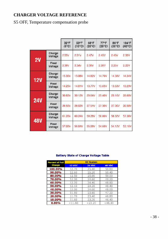
sources are producing power. (See: Battery State of charge)
The table will allow conversion of the voltage readings obtained to an estimate of state of charge.
The table is good for batteries at 77ºF that has been at rest for 3 hours or more. If the batteries are
at a lower temperature you can expect lower voltage readings. When your voltage reading is
about equal to the battery "nominal voltage" your battery is about 60% discharged.
Keep the tops of your batteries clean and check that cables are tight. Do not tighten or remove
cables while charging or discharging. Any spark around batteries can cause a dangerous
hydrogen explosion inside and ruin one of the cells. When some cells show a variation of 0.05
specific gravity from each other an equalizing charge is recommended. This is a long steady
overcharge, bringing the battery to a gassing or bubbling state. Consult recommendations of the
battery manufacture for equalization charges. Do not equalize sealed or gel type batteries.
The batteries should be charged before checking the electrolyte level which should be about 1/ 2"
above the top of the plates, NOT completely full. Most batteries have a plastic cup that the
electrolyte should just touch when full. Don't overfill the batteries or the electrolyte will spill out of
the batteries during charging. Refill the batteries with distilled water. Regular tap water may
have high mineral levels that can contaminate the battery chemistry and reduce battery life.
Check the battery cable connections for tightness and corrosion. Torque all DC cable connections

- 19 -
to 10-12 foot-pounds. If any corrosion is found, disconnect the cables and carefully clean them
with a mild solution of baking soda and water. DO NOT ALLOW THE SOLUTION TO ENTER
THE BATTERY. Wash and replace the caps to the battery. Rinse the top of the battery with
clean water when finished.
To reduce the amount of corrosion on the battery terminals, coat them with a thin layer of
petroleum jelly or anti-corrosion grease available from automotive parts stores or battery suppliers.
Do not apply any material between the battery terminal and the cable lugs, the connection should
be metal to metal. Apply the protective material after the bolts have been tightened.
3.3 Battery ConfigurationsBattery banks of substantial size can be configured by connecting several smaller batteries.
There are three ways to do this: parallel, series, or series -parallel. Torque all DC cable
connections to 10-12 foot-pounds.
3.3.1 Parallel ConnectionBatteries are connected in parallel when all of the positive terminals of a group of batteries are
connected, and then all of the negative terminals of a group of batteries are connected. In a
parallel configuration the battery bank has the same voltage as a single battery and an
amp/hour rating equal to the sum of the individual batteries. This usually is done only with 12
voltage battery -inverter systems.
3.3.2 Series ConnectionWhen batteries are connected with the positive terminal of one to the negative terminal of the
next, they are connected in series. In a series configuration the battery bank has the same
amp/hour rating as a single battery and an overall voltage equal to the sum of the individual
batteries. This is common with 24 volt or higher battery-inverter systems.

- 20 -
3.3.3 Series-Parallel ConnectionAs the name implies, both of the above techniques are used in combination. The result is an
increase in both the voltage and the capacity of the total battery bank. This is done very often to
make a larger, higher voltage battery bank out of several smaller, lower voltage batteries. This
is common with all battery-inverter system voltages.
3.4 Battery InstallationCaution: Batteries can produce extremely high currents during short-circuits. Be very careful
while working with them. Read the important safety instructions at the beginning of this
manual and the battery supplier precautions before installing the INVERTER and batteries.
3.4.1 Battery LocationBattery should be located in a place that allows the user easy access to battery caps and
terminals. At least two feet of clearance above batteries is recommended (when using
non-sealed batteries) to allow the user to check the electrolyte level in batteries. The batteries
should be located as close as possible to the INVERTER but cannot limit access to the
INVERTER and the Inverter AC/DC connections. The batteries are best located at the end of
the Powertek INVERTER where the DC connections are located. Do not locate the inverter in
the same compartment with non-sealed batteries (sealed batteries are acceptable). The gasses
produced by these batteries during charging are very corrosive and will shorten the life of the
inverter.
Battery to inverter wiring should be as short as possible to avoid excessive drop in voltage.
See 4.2.1 for correct cable sizing.

- 21 -
3.4.2 Battery EnclosureTo prevent access from untrained personal, batteries should be protected within a ventilated,
locked enclosure or room. The enclosure should be ventilated to the outdoors from the highest
point to prevent accumulation of hydrogen gasses that are released in the battery charging
process. An air intake vent should also be provided at a low point in the enclosure to allow for
good ventilation. For most systems a one inch diameter vent pipe from the top of the
enclosure is adequate to prevent accumulation of hydrogen. A sloped top can help direct the
hydrogen to the vent location and prevent pockets of hydrogen from occurring. The enclosure
should also be capable of holding at least one battery cell worth of electrolyte in the event a spill
or leak occurs. The enclosure should be made of acid resistant material or have an acid
resistant finish applied to resist the corrosion from spilled electrolyte and released fumes. If
the batteries are located out doors the enclosure should be rainproof and have mesh screens
over any openings to prevent insects and rodents from entering. Before placing the batteries
in the enclosure cover the bottom with a layer of baking soda to neutralize any acid that might
be spilled in the future.
3.4.3 Battery CablesHeavy cables should be used to connect individual batteries to configure a larger battery bank.The actual size of the cable depends upon whether the batteries are connected in parallel or
series. It is better to connect the batteries first in series and then in parallel when connecting
smaller batteries. The best option is to connect the batteries both in series and parallel in a
configuration known as "cross-trying'. This requires additional cables but reduces imbalances
in the battery and can improve the overall performance. Consult your battery supplier for more
information regarding the hook-up configuration required for your system.

- 22 -
4. Installation4.1 Inverter Installation
Tools required for AC wiring connections are: wire strippers, 1/2"(13MM) open-end wrench or
socket, Phillips screwdriver #2, slotted screw driver 1/4"(6MM) blade. Torque all AC wiring
connections to 15-20 inch-pounds.
4.1.1 EnvironmentThe Powertek INVERTER is a sophisticated electronic device and should be treated
accordingly. When selecting the operating environment for the inverter, keep in mind that is a
highly complex microprocessor controlled device and must be treated similar to other electronic
devices such as televisions and computers. The use of coated circuit boards, plated copper bus
bars, powder coated metal components, and stainless steel fasteners allows the unit to function
in hostile environments, however, in an environment with high condensation (one in which
humidity and/or temperature change causes water to form on components) all the ingredients
for electrolysis are present - water, electricity, and metals and therefore the life expectancy of
the inverter cannot be determined and the warranty is voided.
The INVERTER should be installed in a dry protected location away from sources of high
temperature and moisture. Exposure to saltwater is particularly destructive and potentially
hazardous.
Locate the INVERTER as close as possible to the batteries in order to keep the battery cables
short. However, do not locate the inverter in the same compartment as non-sealed batteries.
Caution: Do not mount the inverter in a closed container. Unrestricted airflow is necessary
in order for the inverter to operate at high power for sustained periods of time. Without
ventilation, the protection circuitry will activate and reduce the maximum power available.
4.1.2 System GroundingGrounding requirements vary by country and application. Consult local codes and the NEC for
specific requirements.

- 23 -
4.1.2.1 Equipment or Chassis GroundThis is the simplest part of grounding. The idea is to connect the metallic chassis of the
various enclosures to have them at the same voltage level. This reduces the potential for
electric shock. It also provides a path for fault currents to flow resulting in blown fuses or tripped
circuit breakers. The size of the connecting conductors should be coordinated with the size of
the over current devices involved. Under some circumstances the conduit and enclosures
themselves will provide the current paths.
4.1.2.2 Ground Electrodes / Ground RodsThere are two purposes of the grounding electrode, which is often called a ground rod. The first
is to "bleed" off any electrical charge that may accumulate in the electrical system. The second
is to provide a path for dissipating induced electromagnetic energy or lightning energy. The size
of the conductor of the grounding electrode or grounding system is usually based on the size of
the largest conductor in the system. Most systems use a 5/8' (16mm) copper plated rod 6 feet
(2 mts) long driven into the earth as a grounding electrode. It is also common to use copper
wire placed in the concrete foundation of the building as a grounding system. While either
method may be acceptable, the local code will prevail. Connection to the ground electrode
should be done with special clamps located above ground where they can be periodically
inspected.
Multiple ground rods are recommended in larger systems. Most electrical codes require multiple
ground rods connected by a separate wire with its own set of clamps.
Well casings and water pipes can be used as grounding electrodes. Under no circumstance
should a gas pipe or line be used. Consult local codes and the NEC for more information.
4.1.3 Bonding the Grounding System to the Neutral and Negative ConductorsThis is the most confusing part of grounding. The idea is to connect one of the current carrying
conductors, usually the AC neutral and DC negative, to the grounding system.
This is why we call one of the wires "neutral" in the North American electrical systems. This way
you can touch this wire and the grounding system and not receive a shock. When the other
ungrounded conductor, the hot or positive, touches the grounding system, current will flow
through it to the point of connection to the grounded conductor and back to the source. This will
cause the over current protection to stop the flow of current, protecting the system. The point of
connection between the grounding system and the current carrying conductor is often called a
"bond." It is usually located on the enclosure of the current protection device. Although the

- 24 -
point of connection can be made on the inverter, codes do not generally allow it because the
inverter is considered a "serviceable” item which may be removed from the system. In
residential systems the point of connection is located at the service entrance panel.
In some countries the neutral is not bonded to the grounding system. This means you may not
know when a fault has occurred since the over current device will not trip unless a "double" fault
occurs. This type of system is used in some marine electrical codes.
Bonding must be done at only one point in an electrical system. The Powertek has two
separate power sources- a DC and an AC source. This means that two bonding points will
occur in all inverter applications. The bonding point will also be connected to the chassis
ground conductors. It is common to have two separate conductors for connecting the ground
electrode and the two bonding points. Each conductor must use a separate clamp.
4.2 Installation Diagrams
4.2.1 DC Wire SizePOWERTEK DC terminal:
The picture at the left illustrates the proper method to connect battery cables to the
- 25 -
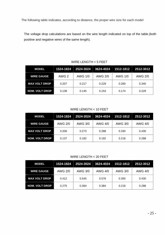
The following table indicates, according to distance, the proper wire size for each model
The voltage drop calculations are based on the wire length indicated on top of the table.(both
positive and negative wires of the same length).
WIRE LENGTH < 5 FEET
MODEL 1524-1824 2524-3024 3624-4024 1512-1812 2512-3012
WIRE GAUGE AWG 2 AWG 1/0 AWG 2/0 AWG 1/0 AWG 2/0
MAX VOLT DROP 0.207 0.217 0.229 0.260 0.340
NOM. VOLT DROP 0.138 0.145 0.153 0.174 0.229
WIRE LENGTH < 10 FEET
MODEL 1524-1824 2524-3024 3624-4024 1512-1812 2512-3012
WIRE GAUGE AWG 2/0 AWG 3/0 AWG 4/0 AWG 3/0 AWG 4/0
MAX VOLT DROP 0.206 0.273 0.288 0.330 0.430
NOM. VOLT DROP 0.137 0.182 0.192 0.218 0.288
WIRE LENGTH < 20 FEET
MODEL 1524-1824 2524-3024 3624-4024 1512-1812 2512-3012
WIRE GAUGE AWG 2/0 AWG 3/0 AWG 4/0 AWG 3/0 AWG 4/0
MAX VOLT DROP 0.412 0.545 0.576 0.300 0.430
NOM. VOLT DROP 0.275 0.364 0.384 0.218 0.288
- 26 -
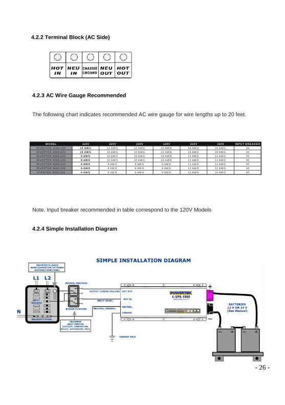
4.2.2 Terminal Block (AC Side)
4.2.3 AC Wire Gauge Recommended
The following chart indicates recommended AC wire gauge for wire lengths up to 20 feet.
Note. Input breaker recommended in table correspond to the 120V Models
4.2.4 Simple Installation Diagram
M O D EL 120V 220V 230V 120V 220V 230V IN PU T B R EAK ERIN VERTER 1500-12V 10 AW G 12 AW G 12 AW G 12 AW G 16 AW G 16 AW G 20IN VERTER 1800-24V 10 AW G 10 AW G 10 AW G 12 AW G 16 AW G 16 AW G 20IN VERTER 2000-24V 8 AW G 10 AW G 10 AW G 10 AW G 14 AW G 14 AW G 25IN VERTER 2500-24V 8 AW G 10 AW G 10 AW G 10 AW G 14 AW G 14 AW G 30IN VERTER 3000-24V 6 AW G 8 AW G 8 AW G 8 AW G 14 AW G 14 AW G 40IN VERTER 3600-24V 6 AW G 8 AW G 8 AW G 8 AW G 12 AW G 12 AW G 50N VERTER 4000-24V 6 AW G 6 AW G 6 AW G 8 AW G 10 AW G 10 AW G 50
- 27 -
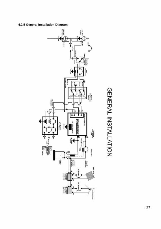
4.2.5 General Installation Diagram
- 28 -
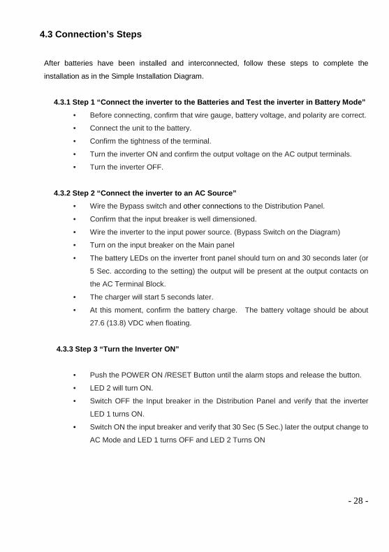
4.3 Connection’s Steps
After batteries have been installed and interconnected, follow these steps to complete the
installation as in the Simple Installation Diagram.
4.3.1 Step 1 “Connect the inverter to the Batteries and Test the inverter in Battery Mode” Before connecting, confirm that wire gauge, battery voltage, and polarity are correct.
Connect the unit to the battery.
Confirm the tightness of the terminal.
Turn the inverter ON and confirm the output voltage on the AC output terminals.
Turn the inverter OFF.
4.3.2 Step 2 “Connect the inverter to an AC Source” Wire the Bypass switch and other connections to the Distribution Panel.
Confirm that the input breaker is well dimensioned.
Wire the inverter to the input power source. (Bypass Switch on the Diagram)
Turn on the input breaker on the Main panel
The battery LEDs on the inverter front panel should turn on and 30 seconds later (or
5 Sec. according to the setting) the output will be present at the output contacts on
the AC Terminal Block.
The charger will start 5 seconds later.
At this moment, confirm the battery charge. The battery voltage should be about
27.6 (13.8) VDC when floating.
4.3.3 Step 3 “Turn the Inverter ON”
Push the POWER ON /RESET Button until the alarm stops and release the button.
LED 2 will turn ON.
Switch OFF the Input breaker in the Distribution Panel and verify that the inverter
LED 1 turns ON.
Switch ON the input breaker and verify that 30 Sec (5 Sec.) later the output change to
AC Mode and LED 1 turns OFF and LED 2 Turns ON
- 29 -
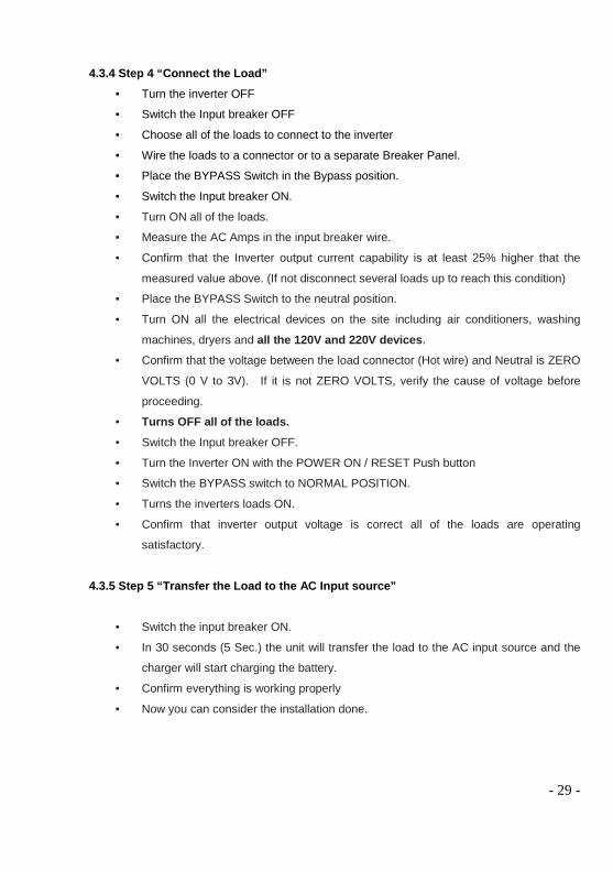
4.3.4 Step 4 “Connect the Load” Turn the inverter OFF
Switch the Input breaker OFF
Choose all of the loads to connect to the inverter
Wire the loads to a connector or to a separate Breaker Panel.
Place the BYPASS Switch in the Bypass position.
Switch the Input breaker ON.
Turn ON all of the loads.
Measure the AC Amps in the input breaker wire.
Confirm that the Inverter output current capability is at least 25% higher that the
measured value above. (If not disconnect several loads up to reach this condition)
Place the BYPASS Switch to the neutral position.
Turn ON all the electrical devices on the site including air conditioners, washing
machines, dryers and all the 120V and 220V devices.
Confirm that the voltage between the load connector (Hot wire) and Neutral is ZERO
VOLTS (0 V to 3V). If it is not ZERO VOLTS, verify the cause of voltage before
proceeding.
Turns OFF all of the loads. Switch the Input breaker OFF.
Turn the Inverter ON with the POWER ON / RESET Push button
Switch the BYPASS switch to NORMAL POSITION.
Turns the inverters loads ON.
Confirm that inverter output voltage is correct all of the loads are operating
satisfactory.
4.3.5 Step 5 “Transfer the Load to the AC Input source”
Switch the input breaker ON.
In 30 seconds (5 Sec.) the unit will transfer the load to the AC input source and the
charger will start charging the battery.
Confirm everything is working properly
Now you can consider the installation done.
- 30 -
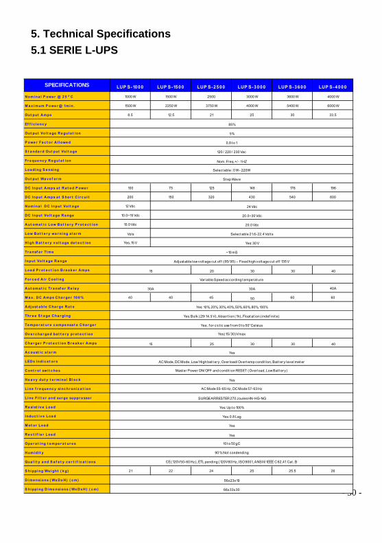
5. Technical Specifications5.1 SERIE L-UPS
8. Troubleshooting
SPECIFICATIONS LUP S-1000 LUP S-1500 LUP S-2500 LUP S-3000 LUP S-3600 LUP S-4000
N omi na l P owe r @ 2 5 o C 1000 W 1500 W 2500 3000 W 3600 W 4000 W
M a x i mum P owe r @ 1mi n. 1500 W 2250 W 3750 W 4000 W 5400 W 6000 W
Out put A mps 8.5 12.5 21 25 30 33.5
Ef f i c i e nc y
Out put Vol t a ge R e gul a t i on
P owe r Fa c t or A l l owe d
S t a nda r d Out put Vol t a ge
Fr e que nc y R e gul a t i on
Loa di ng S e nsi ng
Out put Wa v e f or m
D C I nput A mps a t R a t e d P owe r 100 75 125 148 176 196
D C I nput A mps a t S hor t C i r c ui t 200 150 320 430 540 600
N omi na l D C I nput Vol t a ge 12 Vdc
D C I nput Vol t a ge R a nge 10.0~15 Vdc
A ut oma t i c Low B a t t e r y P r ot e c t i on 10.0 Vdc
Low B a t t e r y wa r ni ng a l a r mSelect able 10.9-11.2
Vols
H i gh B a t t e r y v ol t a ge de t e c t i on Yes, 15 V
Tr a nsf e r T i me
I nput Vol t a ge R a nge
Loa d P r ot e c t i on B r e a k e r A mps 20 30 30 40
For c e d A i r C ool i ng
A ut oma t i c Tr a nsf e r R e l a y 40A
M a x . D C A mps C ha r ge r 10 0 % 40 40 45 50 60 60
A dj ust a bl e C ha r ge R a t e
Thr e e S t a ge C ha r gi ng
Te mpe r a t ur e c ompe nsa t e C ha r ge r
Ov e r c ha r ge d ba t t e r y pr ot e c t i on
C ha r ge r P r ot e c t i on B r e a k e r A mps 25 30 30 40
A c oust i c a l a r m
LED s I ndi c a t or s
C ont r o l swi t c he s
H e a v y dut y t e r mi na l B l oc k
Li ne f r e que nc y si nc hr oni z a t i on
Li ne F i l t e r a nd sur ge suppr e ssor
R e si st i v e Loa d
I nduc t i v e Loa d
M ot or Loa d
R e c t i f i e r Loa d
Ope r a t i ng t e mpe r a t ur e s
H umi di t y
Qua l i t y a nd S a f e t y c e r t i f i c a t i ons
S hi ppi ng We i ght ( k g) 21 22 24 25 25.5 26
D i me nsi ons ( Wx D x H ) ( c m)
S hi ppi ng D i me nsi ons ( Wx D x H ) ( c m)
Select able : 0 W - 220W
~10 mS
85%
20.0~30 Vdc
20.0 Vdc
5%
0.8 t o 1
Nom. Freq.+/ - 1 HZ
120 / 220 / 230 Vac
15
Var iable Speed according t emperat ure
Adjust able low volt age cut of f (85/ 95) – Fixed high volt age cut of f 135 V
30A 30A
Yes: 10%, 20%, 30%, 40%, 50%, 60%, 80%, 100%
Yes: Bulk (29/ 14.5 V) , Absort ion (1h) , Float at ion ( indef init e)
Yes:, f or ciclic use f rom 0 t o 50° Celsius
Yes
AC Mode, DC Mode, Low/ High bat t ery, Over load/ Overt emp condit ion, Bat t ery level met er
Yes
15
66x33x30
56x23x19
St ep Wave
24 Vdc
Select able 21.6-22.4 Volt s
Yes: 30 V
Yes
SURGE ARRESTER 270 Joules HN-HG-NG
Yes: Up t o 100%
Yes: 0.8 Lag
CE (120V 50-60 Hz), ETL pending (120V 60 Hz, ISO 9001, ANSIII/ IEEE C 62.41 Cat . B
Yes (15/ 30)V max
AC Mode 55-65 Hz, DC Mode 57-63 Hz
10 t o 50 oC
90 % Not condending
Mast er Power ON/ OFF and condit ion RESET (Over load, Low Bat t ery)
Yes
- 31 -
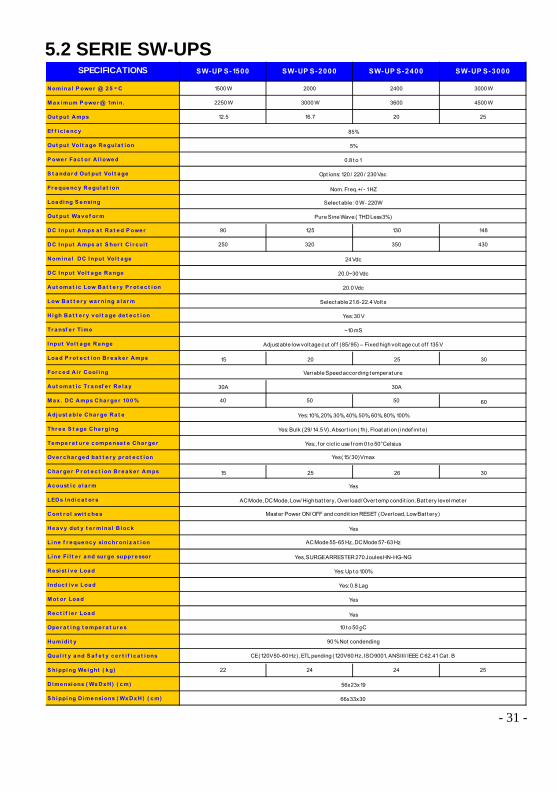
5.2 SERIE SW-UPSSPECIFICATIONS SW-UP S-1500 SW-UP S-2000 SW-UP S-2400 SW-UP S-3000
Nomi na l P owe r @ 2 5 o C 1500 W 2000 2400 3000 W
M a x i mum P owe r @ 1mi n. 2250 W 3000 W 3600 4500 W
Out put Amps 12.5 16.7 20 25
Ef f i c i e nc y
Out put Vol t a ge Re gul a t i on
P owe r Fa c t or A l l owe d
S t a nda r d Out put Vol t a ge
Fr e que nc y Re gul a t i on
Loa di ng S e nsi ng
Out put Wa v e f or m
DC I nput Amps a t Ra t e d P owe r 90 125 130 148
DC I nput Amps a t S hor t C i r c ui t 250 320 350 430
Nomi na l DC I nput Vol t a ge
DC I nput Vol t a ge Ra nge
Aut oma t i c Low Ba t t e r y P r ot e c t i on
Low Ba t t e r y wa r ni ng a l a r m
Hi gh Ba t t e r y v ol t a ge de t e c t i on
Tr a nsf e r Ti me
I nput Vol t a ge Ra nge
Loa d P r ot e c t i on Br e a k e r Amps 20 25 30
For c e d A i r Cool i ng
Aut oma t i c Tr a nsf e r Re l a y
M a x . DC Amps Cha r ge r 10 0 % 40 50 50 60
Adj ust a bl e Cha r ge Ra t e
Thr e e S t a ge Cha r gi ng
Te mpe r a t ur e c ompe nsa t e Cha r ge r
Ov e r c ha r ge d ba t t e r y pr ot e c t i on
Cha r ge r P r ot e c t i on Br e a k e r Amps 25 26 30
Ac oust i c a l a r m
LEDs I ndi c a t or s
Cont r ol swi t c he s
He a v y dut y t e r mi na l B l oc k
Li ne f r e que nc y si nc hr oni z a t i on
Li ne Fi l t e r a nd sur ge suppr e ssor
Re si st i v e Loa d
I nduc t i v e Loa d
M ot or Loa d
Re c t i f i e r Loa d
Ope r a t i ng t e mpe r a t ur e s
Humi di t y
Qua l i t y a nd S a f e t y c e r t i f i c a t i ons
S hi ppi ng We i ght ( k g) 22 24 24 25
Di me nsi ons ( Wx Dx H) ( c m)
S hi ppi ng D i me nsi ons ( Wx Dx H) ( c m)
Select able : 0 W - 220W
~10 mS
Adjust able low volt age cut of f (85/ 95) – Fixed high volt age cut of f 135 V
30A
85%
20.0~30 Vdc
20.0 Vdc
5%
0.8 t o 1
Nom. Freq.+/ - 1 HZ
Opt ions: 120 / 220 / 230 Vac
30A
Yes: 10%, 20%, 30%, 40%, 50%, 60%, 80%, 100%
Yes: Bulk (29/ 14.5 V), Absort ion (1h), Float at ion ( indef init e)
Yes:, f or ciclic use f rom 0 t o 50° Celsius
Yes
66x33x30
56x23x19
Yes
Yes, SURGE ARRESTER 270 Joules HN-HG-NG
Yes: Up t o 100%
Yes: 0.8 Lag
CE (120V 50-60 Hz), ETL pending (120V 60 Hz, ISO 9001, ANSIII/ IEEE C 62.41 Cat . B
AC Mode, DC Mode, Low/ High bat t ery, Overload/ Overt emp condit ion, Bat t ery level met er
Yes
15
Pure Sine Wave ( THD Less 3% )
24 Vdc
Select able 21.6-22.4 Volt s
Yes: 30 V
15
Variable Speed according t emperat ure
Yes (15/ 30)V max
AC Mode 55-65 Hz, DC Mode 57-63 Hz
10 t o 50 oC
90 % Not condending
Mast er Power ON/ OFF and condit ion RESET (Overload, Low Bat t ery)
Yes
- 32 -
6. Service and SupportIf you have any questions, contact our representative in the Dominican Republic, ACTEL SRL
(Tel. 809 5651717) and ask for a technical representative.
Please have the following information ready when you call the Local Distributor:.Model number
.Serial number
.Date of failure or problem
.Symptoms of failure or problem
.Customer returns address and contact information
If repair is required, you will be given a Returned Material Authorization (RMA) Number. This
number must appear on the outside of the package and on the Bill of Lading (if applicable). Use
the original packaging or request packaging from the Help Desk or distributor. Units damaged in
shipment as a result of improper packaging are not covered under warranty. A replacement or
repair unit will be shipped, freight prepaid by customer for all warranted units.
- 33 -
7. POWERTEK WarrantyThe POWERTEK warranty is 3 years, covering any failure due to manufacturing and including
spare parts costs during the first year.
The warranty does not cover damages caused by external factors such as: fire, flooding,
electrical accidents, etc.
The warranty does not cover damages caused to devices connected to the unit nor indemnity
& for opportunity cost due to devices out of service.
The warranty is honored in the authorized Service Department and does not cover transport
and technical services done to evaluate or correct nor the dismounting or mounting of the
device.
The unit must be installed by personnel properly trained. In case of damage, a Local Service
Representative should be allowed to inspect the installation condition in order to determine the
cause of damage.
Warranty will not cover damages caused by:
1. Reversing Battery polarity
2. Applying an AC source to the Unit’s output
3. Grounding absence
4. High input voltage that damages the surge suppressor.
Warranty will be voided if:
1. The unit has been opened by unauthorized personal.
2. The unit is in abnormal conditions such as: excessive dirt, wet, visible corrosion or
any other condition that indicates misuse.
3. The owner does not present the Warranty card properly filled out and the purchase
invoice indicating name, date and serial number.

- 34 -
9. TroubleshootingSYMPTOM CAUSE SOLUTION
No output in DC Mode Inverter is turned off Turn unit on
Inverter is disable by low battery, highbattery, Overload, or Overtemp Remove the condition
No output in AC Mode Load breaker is tripped Reset the breaker
Unit stays in DC Mode when inputvoltage is Input voltage is out of range Correct input voltage or change input voltage cut off levels
present. Charger breaker is tripped Reset the breaker
Input breaker at the distribution panel istripped Reset the breaker
Inverter backup time is very short duringblackout Electrolyte level of batteries is too low Add distilled water to correct level
Battery Electrolyte level is too high Carefully remove excess electrolyte.
Batteries are in poor condition Replace batteries
Low Battery LED is always LitWith a Voltage Meter check the battery voltage when the unit is in ACMode. If battery voltage does not increase call Technical Service.
Led 8 (the fourth led on the inverterbattery meter) never turns on Damaged Batteries
Check battery temperature and water consumption. If abnormal, thebatteries may be damaged. Call technical service or replace batteries
Charger breaker trips several secondsafter unit transfers to AC Mode Bypass the Unit and call Technical Service.
Input breaker in the Distribution paneltrips often Incorrect breaker size Switch breaker to correct amp size
Loose breaker contacts Tighten breaker contacts
With Dip Switch decrease to minimum the Amps rate setting and callTechnical Service
Resetable Load breaker trips often Overloading inverter Decrease the load connected to inverter
The unit pass very often to DC Mode Input voltage is out of rangeChange input voltage settings or call an electrician to correct inputvoltage.
If this occurs during starting of heavy loads such as: Motors, Airconditionings, freezers, etc. If so call Technical Service.
Unit does not turn on with Push button Extremely low battery voltage Recharge batteries with a external charger and then turn on the unit
Unit smells burnt but is working Call Technical Service
Unit smells burnt and is not working Call Technical Service
Unit does nothing and no LEDs are lit Call Technical Service
Fan is always On Environment temperature is above 40ºC Ventilate the area
Batteries overheated Replace batteries

- 35 -
9. Technical Information Disclaimer
Any information in any written paper, catalog or User Manual of this products can be changed
without previous notice.
The company makes not warranty as to the accuracy, sufficiency or suitability of any technical
documentation. Furthermore, our company assumes no responsibility or liability for loss or
damage, whether direct, indirect, consequential or incidental which may arise out of the use of
such information. The use of the information will be at the user or distributor own risk.
Pictures or drawings showed in this manual may be slightly different to the product that you
received.

- 36 -
10.Technical NoteCHARGING AGM BATTERIES: Switch S5 OFF
To maximize the life of your AGM Battery, it is important that it is properly
charged.
Both, over and under charging will result in a shortened service life, as with all
lead-acid batteries.
The POWERTEK Inverter has a quality charger and routinely makes sure that the
charging current and voltage are maintained.
CHARGER GUIDELINESFollow these instructions before charging your batteryThe cable connection must be clean and adapted to the battery terminals to ensure
a snug connection.
Allow a fully charge of the batteries after each discharge’s cycle.Charge in a ventilated area as gasses may be released through the pressure relief
valve if the batteries are overcharged.
CHARGING CHARACTERISTICS
The charger has a setting for AGM, use this setting. (Switch S5 OFF)
VOLTAGE REGULATED CHARGER
SETTING THE CURRENT
- 37 -
The initial current is recommended to be set at I1=0.25 x C20 (IMAX=0.35xC20)
in order to fully charge the batteries within reasonable amount of time. It can be
lower, however, please be aware that charge time will increase so make sure the
batteries have enough time to fully charge before being put back into service.
Use Switches S6, S7 and S8 to set the current.
If the battery has a low internal resistance you can increase the charging
current to decrease the charging time.
BULK STAGE
The charger will deliver the initial current I until the stage voltage limit, Uo, is
reached.
ABSORBTION STAGE
The charger should maintain the voltage Uo until the current tapers to I2 or after 2
hours.
FLOAT STAGE AND TERMINATION
The charger can maintain the charging current I2 indefinitely. This stage is ideal
to maintain battery state of charge.
To maximize your battery life a voltage regulated charger with temperature
compensation is strongly recommended if it is use in areas where the temperature
may decrease to “0” deg. Celsius
Some models are provided with its temperature sensor.
- 38 -
CHARGER VOLTAGE REFERENCE
S5 OFF, Temperature compensation probe