Embed Size (px)
Citation preview
Inverter for grid-connected photovoltaic systems
THREE-PHASE 12 ÷ 250KW TOUCH
MULTISTANDARD

pg. 2 / 40
pag. 3 / 40
User manual
RPS SpA via Somalia, 20
20032 Cormano (MI) Tel. +39 02 66327.1
Fax +39 02 66327.231 www.aros-solar.com
No reproduction of any part of this manual, even partial, is permitted without the manufacturer’s authorization. The manufacturer reserves the right to modify the product described herein, in order to improve it, at any time and without notice.
pag. 4 / 40
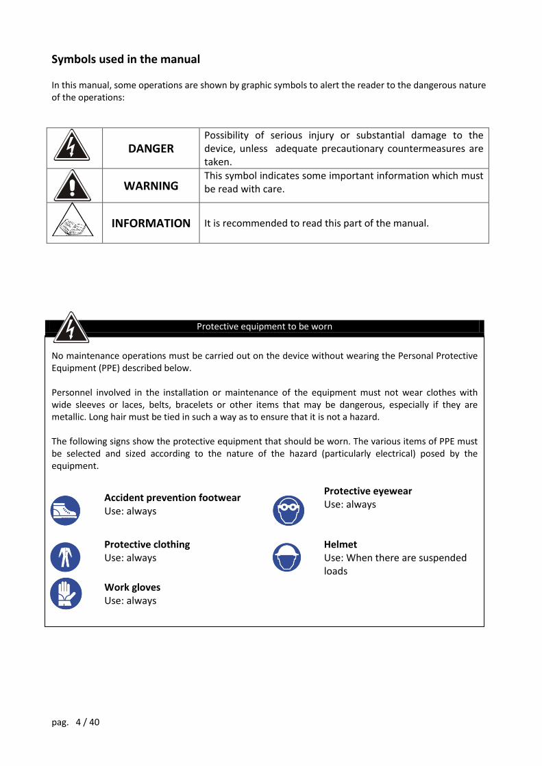
Symbols used in the manual In this manual, some operations are shown by graphic symbols to alert the reader to the dangerous nature of the operations:
DANGER
Possibility of serious injury or substantial damage to the device, unless adequate precautionary countermeasures are taken.
WARNING This symbol indicates some important information which must be read with care.
INFORMATION It is recommended to read this part of the manual.
Protective equipment to be worn
No maintenance operations must be carried out on the device without wearing the Personal Protective Equipment (PPE) described below. Personnel involved in the installation or maintenance of the equipment must not wear clothes with wide sleeves or laces, belts, bracelets or other items that may be dangerous, especially if they are metallic. Long hair must be tied in such a way as to ensure that it is not a hazard. The following signs show the protective equipment that should be worn. The various items of PPE must be selected and sized according to the nature of the hazard (particularly electrical) posed by the equipment.
Accident prevention footwear Use: always
Protective eyewear Use: always
Protective clothing Use: always
Helmet Use: When there are suspended loads
Work gloves Use: always
pag. 5 / 40
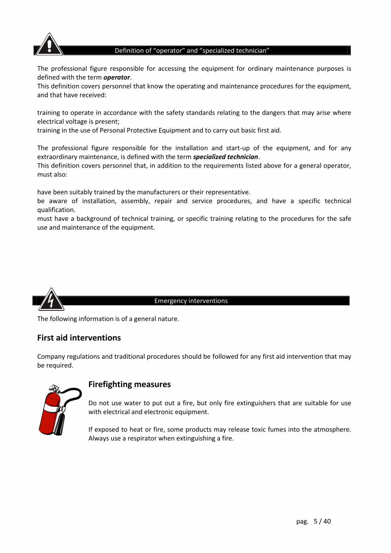
Definition of “operator” and “specialized technician”
The professional figure responsible for accessing the equipment for ordinary maintenance purposes is defined with the term operator. This definition covers personnel that know the operating and maintenance procedures for the equipment, and that have received: training to operate in accordance with the safety standards relating to the dangers that may arise where electrical voltage is present; training in the use of Personal Protective Equipment and to carry out basic first aid. The professional figure responsible for the installation and start-up of the equipment, and for any extraordinary maintenance, is defined with the term specialized technician. This definition covers personnel that, in addition to the requirements listed above for a general operator, must also: have been suitably trained by the manufacturers or their representative. be aware of installation, assembly, repair and service procedures, and have a specific technical qualification. must have a background of technical training, or specific training relating to the procedures for the safe use and maintenance of the equipment.
Emergency interventions
The following information is of a general nature.
First aid interventions Company regulations and traditional procedures should be followed for any first aid intervention that may be required.
Firefighting measures Do not use water to put out a fire, but only fire extinguishers that are suitable for use with electrical and electronic equipment. If exposed to heat or fire, some products may release toxic fumes into the atmosphere. Always use a respirator when extinguishing a fire.
pag. 6 / 40
In the development of its products, the company devotes abundant resources to analyzing the environmental aspects. All our products pursue the objectives defined in the environmental management system developed by the company in compliance with applicable standards. No hazardous materials such as CFCs, HCFCs or asbestos are used in this product. When evaluating packaging, the choice of material has been made favoring recyclable materials. For correct disposal, please separate and identify the type of material of which the packaging is made in the table below. Dispose of all material in compliance with applicable standards in the country in which the product is used.
DESCRIPTION MATERIAL Box Cardboard
Packaging corner Stratocell
Protective bag Polythene
Accessories bag Polythene
DISPOSING OF THE PRODUCT The UPS and the Battery Box contain electronic cards and batteries which are considered TOXIC and HAZARDOUS waste. When the product reaches the end of its operating life, dispose of it in accordance with applicable local legislation. Disposing of the product correctly contributes to respecting the environment and personal health.
ENVIRONMENTAL PROTECTION
pag. 7 / 40
Thank you for choosing our product. Aros Solar Technology is highly specialized in the development and production of equipment for static energy conversion. The inverters of the three-phase SIRIO series are high quality products, carefully designed and manufactured to ensure optimum performance.
GENERAL PRECAUTIONS This manual contains instructions for the use, installation and start-up of SIRIO inverters.
Read the manual carefully before installation. The manual should be kept close at hand and consulted for information on using the equipment before carrying out any operation.
The first connection to be made is the connection between the earth conductor and the terminal with the symbol shown here:
The inverter must not operate without an earth connection.
The equipment must be installed and used in accordance with the instructions contained in this document and in the manner suggested from time to time. Aros Solar Technology is not liable for defects or malfunctions resulting from improper use of the equipment, alterations due to transport or particular environmental conditions, failure or improper servicing, tampering or temporary repairs, and the use or installation by unqualified individuals.
The operating and maintenance personnel and specialized technicians should be adequately trained in the safe use and maintenance of the device. They should always operate with due precaution and wear personal protective equipment (PPE).
Maintenance must not be carried it inside the inverter when it is being powered from the mains or the DC voltage. For maintenance switch the inverter off and open all the other switches. Always use a multimeter to ensure that there are no dangerous voltages.
There are dangerous voltages inside the equipment even when the input and output switches are in the open position; trained personnel must wait around 20 minutes for the capacitors to discharge before working on the inside of the inverter.
The specialized technician must comply scrupulously with the following instructions for the installation and maintenance of the inverter:
o use insulated tools.
o observe polarities.
o if the fuses need replacing, replace only with the same type.
o the replaced components must be disposed of in accordance with the legislation in force in the country of installation.
Do not deactivate the protection devices or ignore the warnings, precautions and alarms described in this manual or those shown on data plates on the equipment.
Promptly replace any danger signals if they should become illegible through usage.
The inverter must be used only with all side and internal panels duly secured and with the front door closed.
Under no circumstances may the structure of the equipment, the devices mounted on it, the operating sequence, etc. be modified, tampered with or altered in any way without first consulting the manufacturers.
pag. 8 / 40
All ordinary and extraordinary maintenance operations must be noted in the appropriate register with the date, time, type of intervention, operator name and any other useful information.
Once the maintenance operations have been concluded, a thorough check should be made in order to ensure that no tools and/or other materials have been left inside the cabinet.
In the event of faults or malfunctions, contact your local distributor or Aros. All repair operations must be carried out by authorized technicians.
Under no circumstances must water be used to clean the internal or external electrical parts of the cabinet.
Do not leave the device exposed to rain or to the elements. The device must be stored and used in premises that comply with the environmental requirements set out in this user manual.
Instructions for use The purchased equipment is intended for professional use in industrial or commercial
environments. Shielded cables must be used for the connections to signaling connectors.
Warning Sale of this product is reserved for competent installers. Installation restrictions or additional
measures may be necessary in order to avoid problems.
CE Mark The inverters of the SIRIO series come with CE marking; when used in accordance with the instructions in this manual, they comply with the requirements of the following directives:
- LV Directive 2006/95/EC. - EMC Directive 2004/108/EC.
No reproduction of any part of this manual, even partial, is permitted without the manufacturer’s authorization. The manufacturer reserves the right to modify the product described herein, in order to improve it, at any time and without notice.
pag. 9 / 40
SUMMARY INTRODUCTION............................................................................................................................... 10 STORAGE......................................................................................................................................... 12 INSTALLATION ENVIRONMENT .................................................................................................... 12 PRELIMINARY OPERATIONS ........................................................................................................ 12
CHECKING THE PACKAGING ................................................................................................................................ 12 POSITIONING ................................................................................................................................... 13 ELECTRICAL SYSTEM SETTINGS ................................................................................................ 14
SYSTEM PROTECTION ................................................................................................................................ 14 PHOTOVOLTAIC FIELD / NETWORK CONNECTIONS .................................................................................... 14 CONNECTORS FOR REMOTE COMMANDS, SIGNALLING AND COMMUNICATIONS .......................................................... 17 CHECK CONNECTIONS ............................................................................................................................... 22
START-UP PROCEDURE ................................................................................................................ 23 FUNCTIONAL CHECK ..................................................................................................................... 24 SHUTDOWN ..................................................................................................................................... 24 PERSONALIZATIONS ..................................................................................................................... 24 OPERATION ..................................................................................................................................... 24 MAINTENANCE ................................................................................................................................ 25 GENERAL CHARACTERISTICS ..................................................................................................... 27 GENERAL CHARACTERISTICS HV VERSION ............................................................................ 31 INVERTER USER PANEL FUNCTIONS. ........................................................................................ 34
GENERAL DESCRIPTION. ............................................................................................................................ 34 ALARM MESSAGES ..................................................................................................................................... 34
COMMAND PANEL MENUS ........................................................................................................... 37 MEASUREMENTS ........................................................................................................................................ 38 LOG ............................................................................................................................................................. 38 CUSTOMIZATIONS ....................................................................................................................................... 38 INFORMATION ............................................................................................................................................. 39
pag. 10 / 40
INTRODUCTION
This document describes the features of the Three-phase Solar Converters of the SIRIO series with isolation transformer.
The SIRIO inverter is used to transfer the energy produced by a photovoltaic generator to the three-phase power distribution system. The MPPT (Maximum Power Point Tracking) feature ensures that the power is drawn from the photovoltaic modules with the operating point continuously optimized in relation to the irradiation conditions, the characteristics of the panels, their temperature and the converter characteristics.
The system is designed to allow it to feed into the network a current with a sinusoidal waveform and uniform power factor in all operating conditions.
The interface between the device and the network has a low frequency, three-phase isolation transformer. This satisfies current legislation and also prevents the injection of continuous current components into the distribution grid. Having such a component also helps protect the inverter in the event of overvoltages on the electrical system.
The operating parameters and electrical values can be displayed locally, by means of the alphanumeric LCD display.
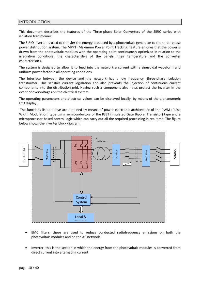
The functions listed above are obtained by means of power electronic architecture of the PWM (Pulse Width Modulation) type using semiconductors of the IGBT (Insulated Gate Bipolar Transistor) type and a microprocessor-based control logic which can carry out all the required processing in real time. The figure below shows the inverter block diagram:
EMC filters: these are used to reduce conducted radiofrequency emissions on both the photovoltaic modules and on the AC network
Inverter: this is the section in which the energy from the photovoltaic modules is converted from direct current into alternating current.
EMC
Filt
er
Control System
Local & Remote
Comunication
PV
AR
RA
Y
MA
INS
AC
Filt
er
LF transformer
EMC
Filt
er
pag. 11 / 40
LF transformer: this has a dual function; it ensures the galvanic separation of the direct current section from the alternating current section and increases the voltage generated by the inverter up to the rated output value
AC filter: its function is to recreate a sinusoidal current waveform by eliminating the high frequencies generated by the inverter stage.
Contactor: separates the inverter from the AC network during periods of non-operation, thus eliminating transformer no-load losses.
DC disconnector: disconnects the photovoltaic field from the inverter to allow maintenance to be carried out on the inverter
AC disconnect switch: disconnects the inverter from the AC network in the event of maintenance and is triggered to protect the network in the event of an internal fault in the AC section of the device
Control system: this is the heart of the entire system that manages all parts of the equipment.
Communications: for local monitoring (display + keyboard) of inverter operation or remote monitoring by means of appropriate electrical connections.
pag. 12 / 40
STORAGE
If the inverter is not installed immediately, it should be stored with its original packaging and protected from humidity and the elements. The storage premises should comply with the following characteristics: Temperature: -25°C ÷ + 60°C (-13°F ÷ 140°F) Relative humidity 95% max Recommended storage temperature is between +5°C and +40°C.
INSTALLATION ENVIRONMENT
The equipment has been designed for indoor installation. The choice of premises for installation should comply with the points set out below: avoid dusty environments; ensure that the floor can support the weight of the inverter; avoid narrow environments that could hinder normal maintenance operations; avoid placing the device in areas exposed to direct sunlight or heat; ensure that the ambient temperature, with inverter operating, is less than: operating temperature: -10 ÷ +50°C maximum temperature for 8 hours a day: + 45°C average temperature for 24 hours: + 35°C N.B.: the operating temperature recommended for the lifetime of the inverter is between 10°C and 35°C. A heat dissipation system is required to keep the temperature in the installation site within this field (the value of the power dissipated by the inverter is shown in the section “GENERAL CHARACTERISTICS).
PRELIMINARY OPERATIONS
Checking the packaging
Upon receipt of the inverter, check that the packaging has not been damaged during shipping.
Check that neither of the two impact resistant devices on the packaging has turned red; if one of them should be red, follow the instructions on the packaging.
Care should be taken when removing the packaging in order to avoid scratching the inverter cabinet.
The device must be handled with care; it may be damaged if knocked or dropped.
This technical user manual is supplied with the inverter. The device should only be handled by appropriately trained personnel. It can be unloaded from the vehicle and put into place by lifting the box or the wooden deck to which the equipment is secured with a fork-lift truck. A transpallet or fork-lift truck should be used for the permanent positioning of the equipment, in accordance with the instructions provided below.
pag. 13 / 40
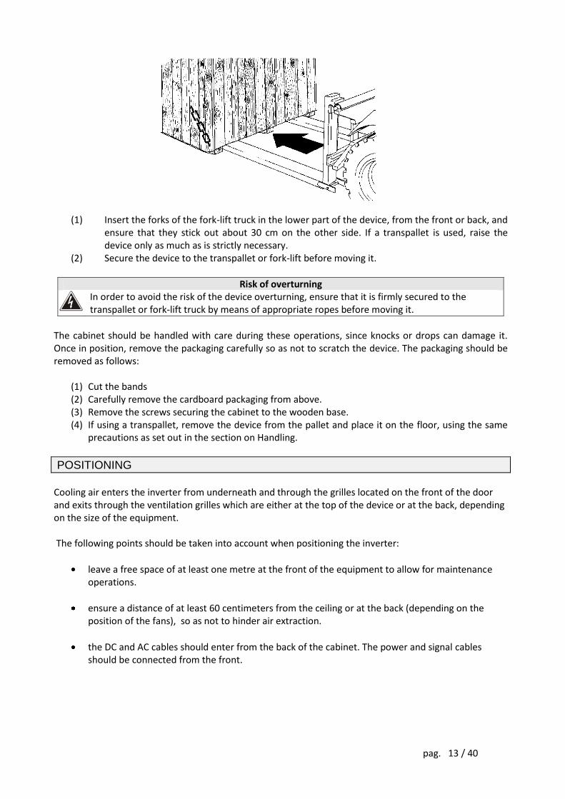
(1) Insert the forks of the fork-lift truck in the lower part of the device, from the front or back, and
ensure that they stick out about 30 cm on the other side. If a transpallet is used, raise the device only as much as is strictly necessary.
(2) Secure the device to the transpallet or fork-lift before moving it.
Risk of overturning In order to avoid the risk of the device overturning, ensure that it is firmly secured to the
transpallet or fork-lift truck by means of appropriate ropes before moving it.
The cabinet should be handled with care during these operations, since knocks or drops can damage it. Once in position, remove the packaging carefully so as not to scratch the device. The packaging should be removed as follows:
(1) Cut the bands (2) Carefully remove the cardboard packaging from above. (3) Remove the screws securing the cabinet to the wooden base. (4) If using a transpallet, remove the device from the pallet and place it on the floor, using the same
precautions as set out in the section on Handling.
POSITIONING
Cooling air enters the inverter from underneath and through the grilles located on the front of the door and exits through the ventilation grilles which are either at the top of the device or at the back, depending on the size of the equipment. The following points should be taken into account when positioning the inverter:
leave a free space of at least one metre at the front of the equipment to allow for maintenance operations.
ensure a distance of at least 60 centimeters from the ceiling or at the back (depending on the position of the fans), so as not to hinder air extraction.
the DC and AC cables should enter from the back of the cabinet. The power and signal cables should be connected from the front.
pag. 14 / 40
ELECTRICAL SYSTEM SETTINGS
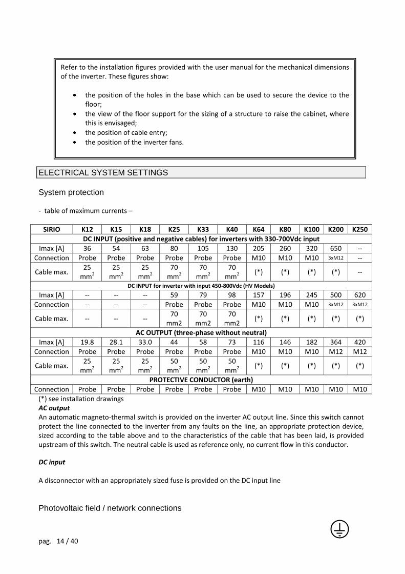
System protection - table of maximum currents –
SIRIO K12 K15 K18 K25 K33 K40 K64 K80 K100 K200 K250
DC INPUT (positive and negative cables) for inverters with 330-700Vdc input
Imax [A] 36 54 63 80 105 130 205 260 320 650 --
Connection Probe Probe Probe Probe Probe Probe M10 M10 M10 3xM12 --
Cable max. 25
mm2 25
mm2 25
mm2 70
mm2 70
mm2 70
mm2 (*) (*) (*) (*) --
DC INPUT for inverter with input 450-800Vdc (HV Models)
Imax [A] -- -- -- 59 79 98 157 196 245 500 620
Connection -- -- -- Probe Probe Probe M10 M10 M10 3xM12 3xM12
Cable max. -- -- -- 70
mm2 70
mm2 70
mm2 (*) (*) (*) (*) (*)
AC OUTPUT (three-phase without neutral)
Imax [A] 19.8 28.1 33.0 44 58 73 116 146 182 364 420
Connection Probe Probe Probe Probe Probe Probe M10 M10 M10 M12 M12
Cable max. 25
mm2 25
mm2 25
mm2 50
mm2 50
mm2 50
mm2 (*) (*) (*) (*) (*)
PROTECTIVE CONDUCTOR (earth)
Connection Probe Probe Probe Probe Probe Probe M10 M10 M10 M10 M10
(*) see installation drawings AC output An automatic magneto-thermal switch is provided on the inverter AC output line. Since this switch cannot protect the line connected to the inverter from any faults on the line, an appropriate protection device, sized according to the table above and to the characteristics of the cable that has been laid, is provided upstream of this switch. The neutral cable is used as reference only, no current flow in this conductor.
DC input A disconnector with an appropriately sized fuse is provided on the DC input line
Photovoltaic field / network connections
Refer to the installation figures provided with the user manual for the mechanical dimensions of the inverter. These figures show:
the position of the holes in the base which can be used to secure the device to the floor;
the view of the floor support for the sizing of a structure to raise the cabinet, where this is envisaged;
the position of cable entry;
the position of the inverter fans.
pag. 15 / 40
The operations described in this chapter must be carried out exclusively by trained personnel. The first connection to be made is the earth conductor, which is indicated with the symbol: THE INVERTER MUST NOT OPERATE WITHOUT AN EARTH CONNECTION.
Before making the connection, open all the switches on the device and ensure that the inverter and the lines to be connected are completely isolated from the power sources (photovoltaic field and AC power line). More specifically, check that:
the line from the photovoltaic field is isolated from the field;
the inverter disconnectors SWIN and SWOUT are in the open position;
there are no dangerous voltages (DC and AC), by using a multimeter on both the cables and the inverter terminals
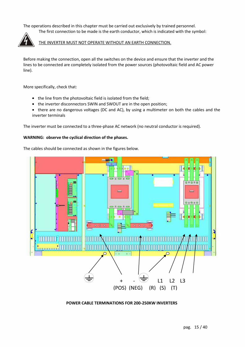
The inverter must be connected to a three-phase AC network (no neutral conductor is required). WARNING: observe the cyclical direction of the phases. The cables should be connected as shown in the figures below.
POWER CABLE TERMINATIONS FOR 200-250KW INVERTERS
+ - L1 L2 L3 (POS) (NEG) (R) (S) (T)
pag. 16 / 40
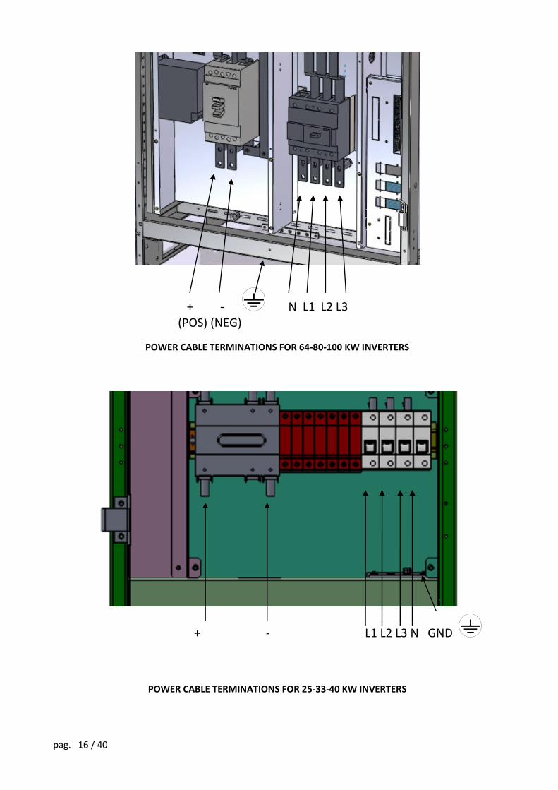
POWER CABLE TERMINATIONS FOR 64-80-100 KW INVERTERS
POWER CABLE TERMINATIONS FOR 25-33-40 KW INVERTERS
+ - L1 L2 L3 N GND
+ - N L1 L2 L3 (POS) (NEG)
pag. 17 / 40
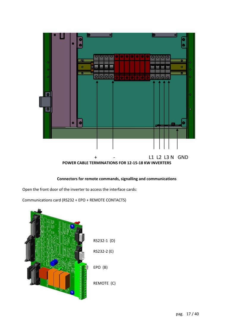
POWER CABLE TERMINATIONS FOR 12-15-18 KW INVERTERS
Connectors for remote commands, signalling and communications Open the front door of the inverter to access the interface cards: Communications card (RS232 + EPO + REMOTE CONTACTS)
RS232-1 (D) RS232-2 (E) EPO (B) REMOTE (C)
+ - L1 L2 L3 N GND
pag. 18 / 40
B - EPO connector (emergency power off command) If jumper B on the connector is opened, the inverter will shut down and disconnect from the distribution grid. The inverter is factory-fitted with the EPO terminals short-circuited. With this input, in a hazardous situation the inverter can be shut down from a remote position simply by pressing a button. Warning: normal operation cannot be restored simply by closing the jumper. This requires an operator to take appropriate action on the inverter control panel.
The EPO command disconnects the inverter from the network, but does not open the connection with the photovoltaic field. Dangerous voltages may still be present in the device.
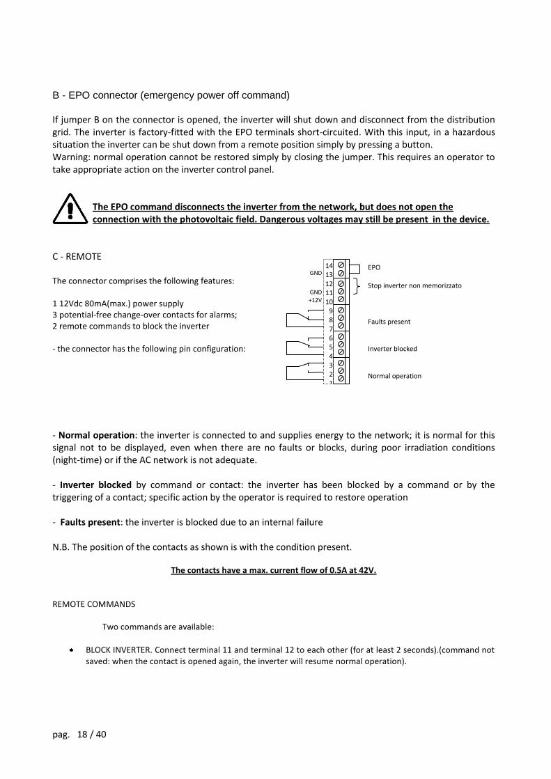
C - REMOTE The connector comprises the following features: 1 12Vdc 80mA(max.) power supply 3 potential-free change-over contacts for alarms; 2 remote commands to block the inverter - the connector has the following pin configuration:
- Normal operation: the inverter is connected to and supplies energy to the network; it is normal for this signal not to be displayed, even when there are no faults or blocks, during poor irradiation conditions (night-time) or if the AC network is not adequate. - Inverter blocked by command or contact: the inverter has been blocked by a command or by the triggering of a contact; specific action by the operator is required to restore operation - Faults present: the inverter is blocked due to an internal failure N.B. The position of the contacts as shown is with the condition present.
The contacts have a max. current flow of 0.5A at 42V. REMOTE COMMANDS
Two commands are available:
BLOCK INVERTER. Connect terminal 11 and terminal 12 to each other (for at least 2 seconds).(command not saved: when the contact is opened again, the inverter will resume normal operation).
GND
GND +12V
EPO Stop inverter non memorizzato Faults present Inverter blocked Normal operation
14 13 12 11 10
9 8 7 6 5 4 3 2 1
pag. 19 / 40
INVERTER EMERGENCY STOP (EPO). If the jumper between terminals 13 and 14 is opened, the inverter will block. (command saved: when the contact is opened again, the inverter will remain in a blocked state until key 8 on the command panel is pressed)
pag. 20 / 40
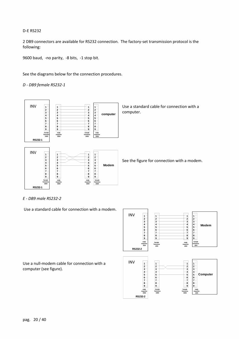
D-E RS232 2 DB9 connectors are available for RS232 connection. The factory-set transmission protocol is the following: 9600 baud, -no parity, -8 bits, -1 stop bit. See the diagrams below for the connection procedures. D - DB9 female RS232-1
Use a standard cable for connection with a computer. See the figure for connection with a modem.
E - DB9 male RS232-2 Use a standard cable for connection with a modem. Use a null-modem cable for connection with a computer (see figure).
1
2
3
4
5
6
7
8
9
1
2
3
4
5
6
7
8
9
1
2
3
4
5
6
7
8
9
1
2
3
4
5
6
7
8
9
female
femmina
DB9
female
femmina
DB9
male
maschio
DB9
male
maschio
DB9
UPS
RS232-1
computer
Modem
1
2
3
4
5
6
7
8
9
1
2
3
4
5
6
7
8
9
1
2
3
4
5
6
7
8
9
1
2
3
4
5
6
7
8
9
female
femmina
DB9
female
femmina
DB9
male
maschio
DB9
male
maschio
DB9
UPS
RS232-1
INV
INV
1
2
3
4
5
6
7
8
9
1
2
3
4
5
6
7
8
9
1
2
3
4
5
6
7
8
9
1
2
3
4
5
6
7
8
9
female
femmina
db9
female
femmina
db9
male
maschio
db9
male
maschio
db9
UPS
RS232-2
Computer
1
2
3
4
5
6
7
8
9
1
2
3
4
5
6
7
8
9
1
2
3
4
5
6
7
8
9
1
2
3
4
5
6
7
8
9
female
femmina
DB9
female
femmina
DB9
male
maschio
DB9
male
maschio
db9
UPS
RS232-2
Modem
INV
INV
pag. 21 / 40
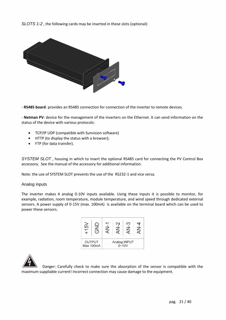
SLOTS 1-2 , the following cards may be inserted in these slots (optional):
- RS485 board: provides an RS485 connection for connection of the inverter to remote devices. - Netman PV: device for the management of the inverters on the Ethernet. It can send information on the status of the device with various protocols:
TCP/IP UDP (compatible with Sunvision software)
HTTP (to display the status with a browser);
FTP (for data transfer). SYSTEM SLOT , housing in which to insert the optional RS485 card for connecting the PV Control Box accessory. See the manual of the accessory for additional information. Note: the use of SYSTEM SLOT prevents the use of the RS232-1 and vice versa. Analog inputs The inverter makes 4 analog 0-10V inputs available. Using these inputs it is possible to monitor, for example, radiation, room temperature, module temperature, and wind speed through dedicated external sensors. A power supply of 0-15V (max. 100mA) is available on the terminal board which can be used to power these sensors.
Danger: Carefully check to make sure the absorption of the sensor is compatible with the maximum suppliable current! Incorrect connection may cause damage to the equipment.
pag. 22 / 40
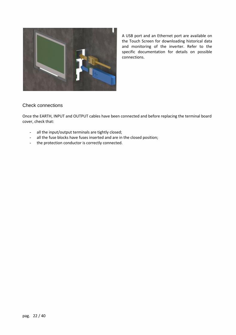
A USB port and an Ethernet port are available on the Touch Screen for downloading historical data and monitoring of the inverter. Refer to the specific documentation for details on possible connections.
Check connections Once the EARTH, INPUT and OUTPUT cables have been connected and before replacing the terminal board cover, check that:
- all the input/output terminals are tightly closed; - all the fuse blocks have fuses inserted and are in the closed position; - the protection conductor is correctly connected.
pag. 23 / 40
START-UP PROCEDURE
Once the electrical connections have been made as indicated above and after replacing the switch cover panel, the inverter can be started up; carry out the following operations in this order:
- open the door of the inverter to access the input switches; - close any input/output switches located outside the inverter; - check that the DC voltage from the photovoltaic field is within the inverter’s accepted range; also
check that the polarity is correct. - close the following inverter switches (the label is shown on the switches panel):
SWIN DC side disconnector SWOUT network side switch
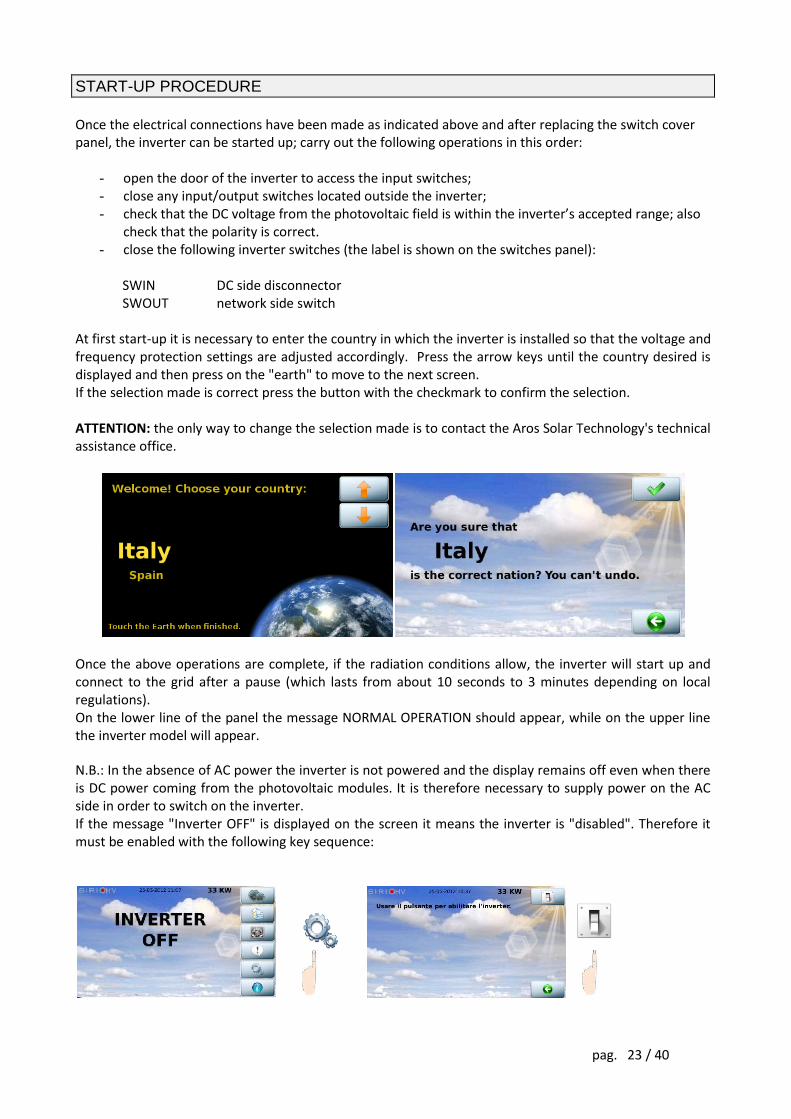
At first start-up it is necessary to enter the country in which the inverter is installed so that the voltage and frequency protection settings are adjusted accordingly. Press the arrow keys until the country desired is displayed and then press on the "earth" to move to the next screen. If the selection made is correct press the button with the checkmark to confirm the selection. ATTENTION: the only way to change the selection made is to contact the Aros Solar Technology's technical assistance office.
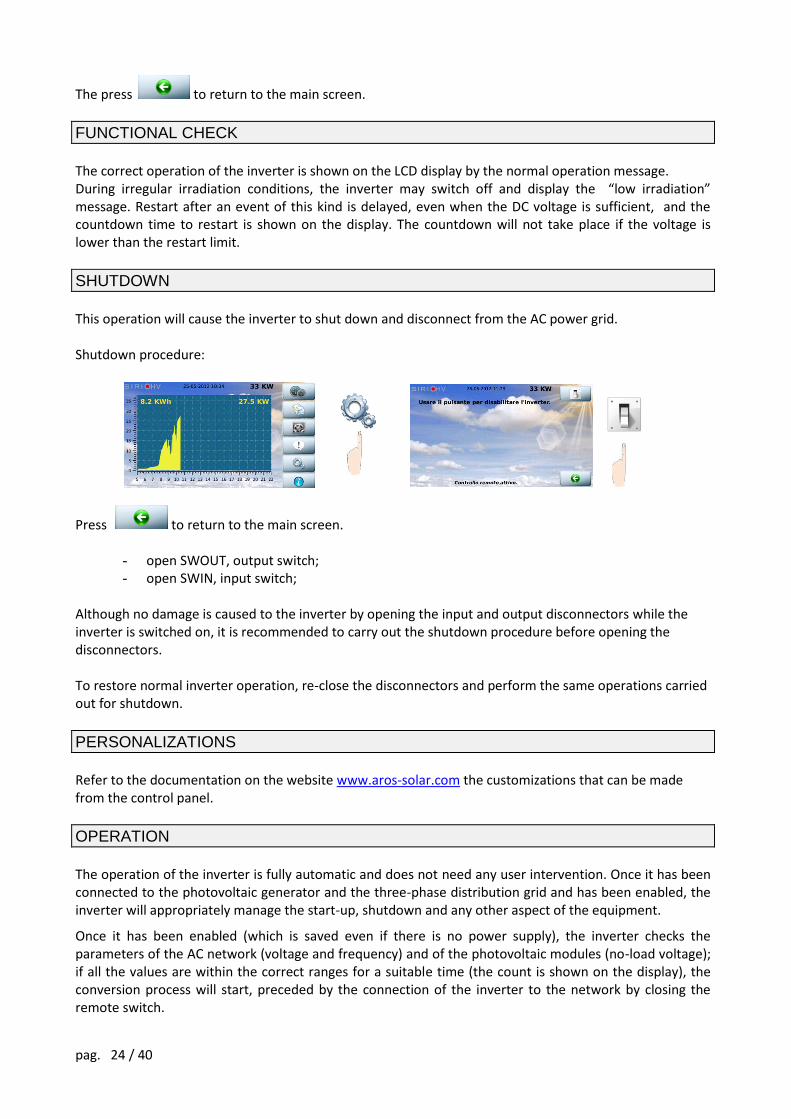
Once the above operations are complete, if the radiation conditions allow, the inverter will start up and connect to the grid after a pause (which lasts from about 10 seconds to 3 minutes depending on local regulations). On the lower line of the panel the message NORMAL OPERATION should appear, while on the upper line the inverter model will appear. N.B.: In the absence of AC power the inverter is not powered and the display remains off even when there is DC power coming from the photovoltaic modules. It is therefore necessary to supply power on the AC side in order to switch on the inverter. If the message "Inverter OFF" is displayed on the screen it means the inverter is "disabled". Therefore it must be enabled with the following key sequence:
pag. 24 / 40
The press to return to the main screen.
FUNCTIONAL CHECK
The correct operation of the inverter is shown on the LCD display by the normal operation message. During irregular irradiation conditions, the inverter may switch off and display the “low irradiation” message. Restart after an event of this kind is delayed, even when the DC voltage is sufficient, and the countdown time to restart is shown on the display. The countdown will not take place if the voltage is lower than the restart limit.
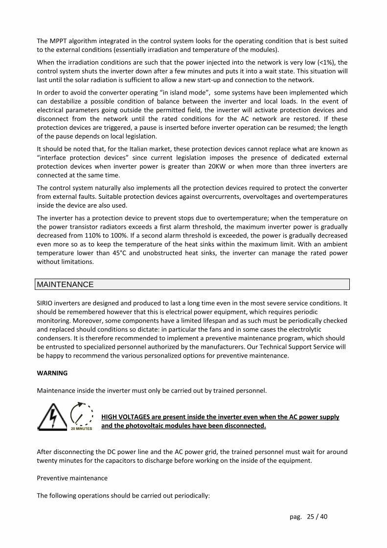
SHUTDOWN
This operation will cause the inverter to shut down and disconnect from the AC power grid. Shutdown procedure:
Press to return to the main screen.
- open SWOUT, output switch; - open SWIN, input switch;
Although no damage is caused to the inverter by opening the input and output disconnectors while the inverter is switched on, it is recommended to carry out the shutdown procedure before opening the disconnectors. To restore normal inverter operation, re-close the disconnectors and perform the same operations carried out for shutdown.
PERSONALIZATIONS
Refer to the documentation on the website www.aros-solar.com the customizations that can be made from the control panel.
OPERATION
The operation of the inverter is fully automatic and does not need any user intervention. Once it has been connected to the photovoltaic generator and the three-phase distribution grid and has been enabled, the inverter will appropriately manage the start-up, shutdown and any other aspect of the equipment.
Once it has been enabled (which is saved even if there is no power supply), the inverter checks the parameters of the AC network (voltage and frequency) and of the photovoltaic modules (no-load voltage); if all the values are within the correct ranges for a suitable time (the count is shown on the display), the conversion process will start, preceded by the connection of the inverter to the network by closing the remote switch.
pag. 25 / 40
The MPPT algorithm integrated in the control system looks for the operating condition that is best suited to the external conditions (essentially irradiation and temperature of the modules).
When the irradiation conditions are such that the power injected into the network is very low (<1%), the control system shuts the inverter down after a few minutes and puts it into a wait state. This situation will last until the solar radiation is sufficient to allow a new start-up and connection to the network.
In order to avoid the converter operating “in island mode”, some systems have been implemented which can destabilize a possible condition of balance between the inverter and local loads. In the event of electrical parameters going outside the permitted field, the inverter will activate protection devices and disconnect from the network until the rated conditions for the AC network are restored. If these protection devices are triggered, a pause is inserted before inverter operation can be resumed; the length of the pause depends on local legislation.
It should be noted that, for the Italian market, these protection devices cannot replace what are known as “interface protection devices” since current legislation imposes the presence of dedicated external protection devices when inverter power is greater than 20KW or when more than three inverters are connected at the same time.
The control system naturally also implements all the protection devices required to protect the converter from external faults. Suitable protection devices against overcurrents, overvoltages and overtemperatures inside the device are also used.
The inverter has a protection device to prevent stops due to overtemperature; when the temperature on the power transistor radiators exceeds a first alarm threshold, the maximum inverter power is gradually decreased from 110% to 100%. If a second alarm threshold is exceeded, the power is gradually decreased even more so as to keep the temperature of the heat sinks within the maximum limit. With an ambient temperature lower than 45°C and unobstructed heat sinks, the inverter can manage the rated power without limitations.
MAINTENANCE
SIRIO inverters are designed and produced to last a long time even in the most severe service conditions. It should be remembered however that this is electrical power equipment, which requires periodic monitoring. Moreover, some components have a limited lifespan and as such must be periodically checked and replaced should conditions so dictate: in particular the fans and in some cases the electrolytic condensers. It is therefore recommended to implement a preventive maintenance program, which should be entrusted to specialized personnel authorized by the manufacturers. Our Technical Support Service will be happy to recommend the various personalized options for preventive maintenance. WARNING Maintenance inside the inverter must only be carried out by trained personnel.
HIGH VOLTAGES are present inside the inverter even when the AC power supply and the photovoltaic modules have been disconnected.
After disconnecting the DC power line and the AC power grid, the trained personnel must wait for around twenty minutes for the capacitors to discharge before working on the inside of the equipment. Preventive maintenance The following operations should be carried out periodically:
pag. 26 / 40
Ensure that the air intake slots (located on the front door and at the back of the cabinet) and the output grilles located on the top of the cabinet are clean. Ensure that the inverter is working properly (the message “NORMAL OPERATION” will appear on the display panel). If an alarm message is displayed, check the meaning in the manual before contacting the technical support service. Check that the operating parameters are within the fields indicated in the section GENERAL CHARACTERISTICS.
Since the photovoltaic modules are a source of energy, just isolating the AC distribution system does not eliminate the danger. PAY THE UTMOST ATTENTION TO THE DC VOLTAGE FROM THE PHOTOVOLTAIC MODULES EVEN IN CONDITIONS OF LOW SOLAR IRRADIATION.

pag. 27 / 40
GENERAL CHARACTERISTICS
SIRIO
Model K12 K15 K18
Input
Max PV power Pmax 14 Kwp 18 Kwp 20 Kwp
Minimum recommended PV power Pmin 9 Kwp 12 Kwp 16 Kwp
Recommended Vo@STC voltage Vo 540-640V
DC voltage range, MPPT Vcc 330-700 V
Max DC voltage Vcc,max 800 V
Start-up voltage Vstart-up 390 V
Max DC current Icc,max 36A 54A 63A
Voltage ripple on modules < 2 %
DC inputs 1
Output
Rated AC power Pca 12KW 15KW 18KW
Max AC power Pca 1h 13.2KW 16.5KW 19.8KW
Rated voltage Vca 400 V trifase (+/-15%)
Rated current Ica 17.3A 21.7 26.0A
Max current Ica 22.4A 28.1A 33.0A
Rated frequency Fca 50 Hz (+2/-3Hz)
Distribution system TT, TN-S, TN-C
Harmonic distortion of the network current
THD% < 3 % with rated power
Power factor cos φ > 0.99 (adj. ± 0.9)
Contribution to short circuit current Icc 33.6A 42.1A 49.5A
Standards
Electromagnetic compatibility YES
CE conformity YES
Protection devices and environmental conditions
Ingress protection EN60529 IP20
Environmental categories Indoor, unconditioned
Overvoltage category (EN62109) II (DC) – III (AC)
Pollution degree 3
Permitted temperature range T -10°C – 50°C (1)
Non condensing relative humidity range
5% - 95%
Maximum height above sea level 1000 m ASL (2)
Air change (with detaT=5°C) m3/h 750 1000 1250
Direction of air flow Intake through the base and the front Extraction from the rear
Max power dissipated (in overload) Ploss 573 W 493 KCal/h
717 W 616 KCal/h
860 W 739 KCal/h
Mechanical
Weight Kg 310 320 340
Dimensions mm 555x720x1400
NOTE: (1) with ambient temperature over 45°C there will be a reduction of max power to the network (2) over 1000m lower the power by 1% for every 100m up to a maximum of 3000
pag. 28 / 40
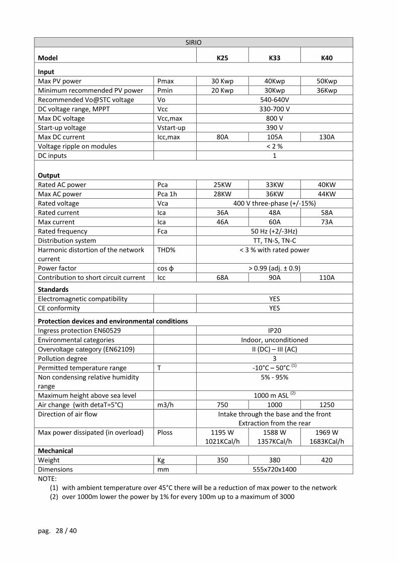
SIRIO
Model K25 K33 K40
Input
Max PV power Pmax 30 Kwp 40Kwp 50Kwp
Minimum recommended PV power Pmin 20 Kwp 30Kwp 36Kwp
Recommended Vo@STC voltage Vo 540-640V
DC voltage range, MPPT Vcc 330-700 V
Max DC voltage Vcc,max 800 V
Start-up voltage Vstart-up 390 V
Max DC current Icc,max 80A 105A 130A
Voltage ripple on modules < 2 %
DC inputs 1
Output
Rated AC power Pca 25KW 33KW 40KW
Max AC power Pca 1h 28KW 36KW 44KW
Rated voltage Vca 400 V three-phase (+/-15%)
Rated current Ica 36A 48A 58A
Max current Ica 46A 60A 73A
Rated frequency Fca 50 Hz (+2/-3Hz)
Distribution system TT, TN-S, TN-C
Harmonic distortion of the network current
THD% < 3 % with rated power
Power factor cos φ > 0.99 (adj. ± 0.9)
Contribution to short circuit current Icc 68A 90A 110A
Standards
Electromagnetic compatibility YES
CE conformity YES
Protection devices and environmental conditions
Ingress protection EN60529 IP20
Environmental categories Indoor, unconditioned
Overvoltage category (EN62109) II (DC) – III (AC)
Pollution degree 3
Permitted temperature range T -10°C – 50°C (1)
Non condensing relative humidity range
5% - 95%
Maximum height above sea level 1000 m ASL (2)
Air change (with detaT=5°C) m3/h 750 1000 1250
Direction of air flow Intake through the base and the front Extraction from the rear
Max power dissipated (in overload) Ploss 1195 W 1021KCal/h
1588 W 1357KCal/h
1969 W 1683KCal/h
Mechanical
Weight Kg 350 380 420
Dimensions mm 555x720x1400
NOTE: (1) with ambient temperature over 45°C there will be a reduction of max power to the network (2) over 1000m lower the power by 1% for every 100m up to a maximum of 3000

pag. 29 / 40
SIRIO
Model K64 K80 K100
Input
Max PV power Pmax 80 Kwp 100Kwp 125 Kwp
Minimum recommended PV power Pmin 55 Kwp 70Kwp 80 Kwp
Recommended Vo@STC voltage Vo 540-640V
DC voltage range, MPPT Vcc 330-700 V
Max DC voltage Vcc,max 800 V
Start-up voltage Vstart-up 390 V
Max DC current Icc,max 205 A 260 A 320 A
Voltage ripple on modules < 1 %
DC inputs 1
Output
Rated AC power Pca 64 KW 80KW 100 KW
Max AC power Pca 1h 71 KW 88 KW 110 KW
Rated voltage Vca 400 V three-phase (+/-15%)
Rated current Ica 92A 115A 145 A
Max current Ica 117A 146A 182A
Rated frequency Fca 50 Hz (+2/-3Hz)
Distribution system TT, TN-S, TN-C
Harmonic distortion of the network current
THD% < 3 % with rated power
Power factor cos φ > 0.99 (adj. ± 0.9)
Contribution to short circuit current Icc 175A 219A 274A
Standards
Electromagnetic compatibility YES
CE conformity YES
Protection devices and environmental conditions
Ingress protection EN60529 IP20
Environmental categories Indoor, unconditioned
Overvoltage category (EN62109) II (DC) – III (AC)
Pollution degree 3
Permitted temperature range T -10°C – 50°C (1)
Non condensing relative humidity range
5% - 95%
Maximum height above sea level 1000 m ASL (2)
Air change (with detaT=5°C) 1760 m3 / h 2400 m3 / h 3300 m3 / h
Direction of air flow Intake through the base and the front Extraction from the top
Max power dissipated (in overload) Ploss 2866 W 2450KCal/h
3821 W 3266KCal/h
5231 W 4471KCal/h
Mechanical
Weight Kg 600 650 720
Dimensions mm 800x800x1900
NOTE: (1) with ambient temperature over 45°C there will be a reduction of max power to the network (2) over 1000m lower the power by 1% for every 100m up to a maximum of 3000m
pag. 30 / 40
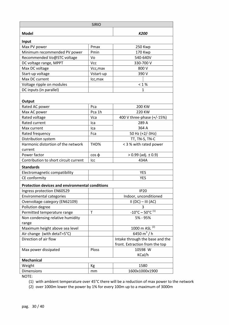
SIRIO
Model K200
Input
Max PV power Pmax 250 Kwp
Minimum recommended PV power Pmin 170 Kwp
Recommended Vo@STC voltage Vo 540-640V
DC voltage range, MPPT Vcc 330-700 V
Max DC voltage Vcc,max 800 V
Start-up voltage Vstart-up 390 V
Max DC current Icc,max
Voltage ripple on modules < 1 %
DC inputs (in parallel) 1
Output
Rated AC power Pca 200 KW
Max AC power Pca 1h 220 KW
Rated voltage Vca 400 V three-phase (+/-15%)
Rated current Ica 289 A 364 A Max current Ica
Rated frequency Fca 50 Hz (+2/-3Hz)
Distribution system TT, TN-S, TN-C
Harmonic distortion of the network current
THD% < 3 % with rated power
Power factor cos φ > 0.99 (adj. ± 0.9)
Contribution to short circuit current Icc 434A
Standards
Electromagnetic compatibility YES
CE conformity YES
Protection devices and environmental conditions
Ingress protection EN60529 IP20
Environmental categories Indoor, unconditioned
Overvoltage category (EN62109) II (DC) – III (AC)
Pollution degree 3
Permitted temperature range T -10°C – 50°C (1)
Non condensing relative humidity range
5% - 95%
Maximum height above sea level 1000 m ASL (2)
Air change (with detaT=5°C) 6450 m3 / h
Direction of air flow Intake through the base and the front. Extraction from the top
Max power dissipated Ploss 10598 W KCal/h
Mechanical
Weight Kg 1580
Dimensions mm 1600x1000x1900
NOTE: (1) with ambient temperature over 45°C there will be a reduction of max power to the network (2) over 1000m lower the power by 1% for every 100m up to a maximum of 3000m
pag. 31 / 40
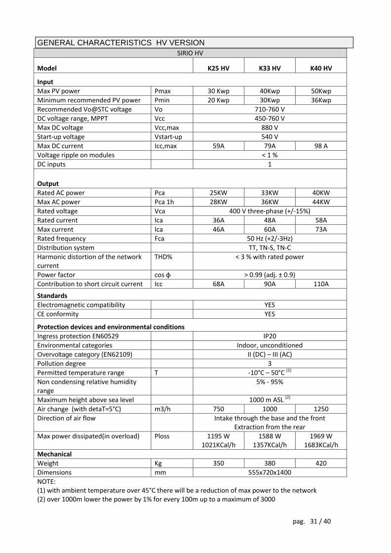
GENERAL CHARACTERISTICS HV VERSION
SIRIO HV
Model K25 HV K33 HV K40 HV
Input
Max PV power Pmax 30 Kwp 40Kwp 50Kwp
Minimum recommended PV power Pmin 20 Kwp 30Kwp 36Kwp
Recommended Vo@STC voltage Vo 710-760 V
DC voltage range, MPPT Vcc 450-760 V
Max DC voltage Vcc,max 880 V
Start-up voltage Vstart-up 540 V
Max DC current Icc,max 59A 79A 98 A
Voltage ripple on modules < 1 %
DC inputs 1
Output
Rated AC power Pca 25KW 33KW 40KW
Max AC power Pca 1h 28KW 36KW 44KW
Rated voltage Vca 400 V three-phase (+/-15%)
Rated current Ica 36A 48A 58A
Max current Ica 46A 60A 73A
Rated frequency Fca 50 Hz (+2/-3Hz)
Distribution system TT, TN-S, TN-C
Harmonic distortion of the network current
THD% < 3 % with rated power
Power factor cos φ > 0.99 (adj. ± 0.9)
Contribution to short circuit current Icc 68A 90A 110A
Standards
Electromagnetic compatibility YES
CE conformity YES
Protection devices and environmental conditions
Ingress protection EN60529 IP20
Environmental categories Indoor, unconditioned
Overvoltage category (EN62109) II (DC) – III (AC)
Pollution degree 3
Permitted temperature range T -10°C – 50°C (1)
Non condensing relative humidity range
5% - 95%
Maximum height above sea level 1000 m ASL (2)
Air change (with detaT=5°C) m3/h 750 1000 1250
Direction of air flow Intake through the base and the front Extraction from the rear
Max power dissipated(in overload) Ploss 1195 W 1021KCal/h
1588 W 1357KCal/h
1969 W 1683KCal/h
Mechanical
Weight Kg 350 380 420
Dimensions mm 555x720x1400
NOTE: (1) with ambient temperature over 45°C there will be a reduction of max power to the network (2) over 1000m lower the power by 1% for every 100m up to a maximum of 3000

pag. 32 / 40
SIRIO HV
Model K64 HV K80 HV K100 HV
Input
Max PV power Pmax 80 Kwp 100Kwp 125 Kwp
Minimum recommended PV power Pmin 55 Kwp 70Kwp 80 Kwp
Recommended Vo@STC voltage Vo 710-760 V
DC voltage range, MPPT Vcc 450-760 V
Max DC voltage Vcc,max 880 V
Start-up voltage Vstart-up 540 V
Max DC current Icc,max 157 A 196 A 245 A
Voltage ripple on modules < 1 %
DC inputs 1
Output
Rated AC power Pca 64 KW 80KW 100 KW
Max AC power Pca 1h 71 KW 88 KW 110 KW
Rated voltage Vca 400 V three-phase (+/-15%)
Rated current Ica 92A 115A 145 A
Max current Ica 117A 146A 182A
Rated frequency Fca 50 Hz (+2/-3Hz)
Distribution system TT, TN-S, TN-C
Harmonic distortion of the network current
THD% < 3 % with rated power
Power factor cos φ > 0.99 (adj. ± 0.9)
Contribution to short circuit current Icc 175A 219A 274A
Standards
Electromagnetic compatibility YES
CE conformity YES
Protection devices and environmental conditions
Ingress protection EN60529 IP20
Environmental categories Indoor, unconditioned
Overvoltage category (EN62109) II (DC) – III (AC)
Pollution degree 3
Permitted temperature range T -10°C – 50°C (1)
Non condensing relative humidity range
5% - 95%
Maximum height above sea level 1000 m ASL (2)
Air change (with detaT=5°C) 1760 m3 / h 2400 m3 / h 3300 m3 / h
Direction of air flow Intake through the base and the front Extraction from the top
Max power dissipated (in overload) Ploss 2866 W 2450KCal/h
3821 W 3266KCal/h
5231 W 4471KCal/h
Mechanical
Weight Kg 600 650 720
Dimensions mm 800x800x1900
NOTE: (5) with ambient temperature over 45°C there will be a reduction of max power to the network (6) over 1000m lower the power by 1% for every 100m up to a maximum of 3000m
pag. 33 / 40
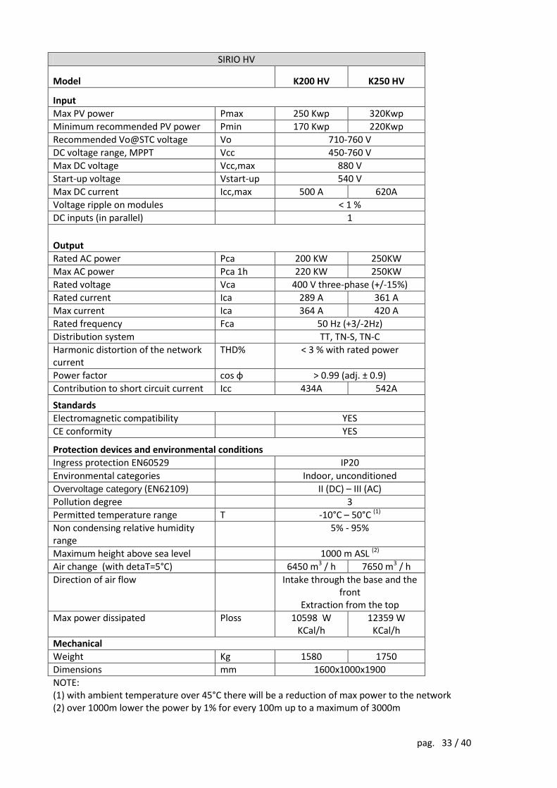
SIRIO HV
Model K200 HV K250 HV
Input
Max PV power Pmax 250 Kwp 320Kwp
Minimum recommended PV power Pmin 170 Kwp 220Kwp
Recommended Vo@STC voltage Vo 710-760 V
DC voltage range, MPPT Vcc 450-760 V
Max DC voltage Vcc,max 880 V
Start-up voltage Vstart-up 540 V
Max DC current Icc,max 500 A 620A
Voltage ripple on modules < 1 %
DC inputs (in parallel) 1
Output
Rated AC power Pca 200 KW 250KW
Max AC power Pca 1h 220 KW 250KW
Rated voltage Vca 400 V three-phase (+/-15%)
Rated current Ica 289 A 361 A
Max current Ica 364 A 420 A
Rated frequency Fca 50 Hz (+3/-2Hz)
Distribution system TT, TN-S, TN-C
Harmonic distortion of the network current
THD% < 3 % with rated power
Power factor cos φ > 0.99 (adj. ± 0.9)
Contribution to short circuit current Icc 434A 542A
Standards
Electromagnetic compatibility YES
CE conformity YES
Protection devices and environmental conditions
Ingress protection EN60529 IP20
Environmental categories Indoor, unconditioned
Overvoltage category (EN62109) II (DC) – III (AC)
Pollution degree 3
Permitted temperature range T -10°C – 50°C (1)
Non condensing relative humidity range
5% - 95%
Maximum height above sea level 1000 m ASL (2)
Air change (with detaT=5°C) 6450 m3 / h 7650 m3 / h
Direction of air flow Intake through the base and the front
Extraction from the top
Max power dissipated Ploss 10598 W KCal/h
12359 W KCal/h
Mechanical
Weight Kg 1580 1750
Dimensions mm 1600x1000x1900
NOTE: (1) with ambient temperature over 45°C there will be a reduction of max power to the network (2) over 1000m lower the power by 1% for every 100m up to a maximum of 3000m
pag. 34 / 40
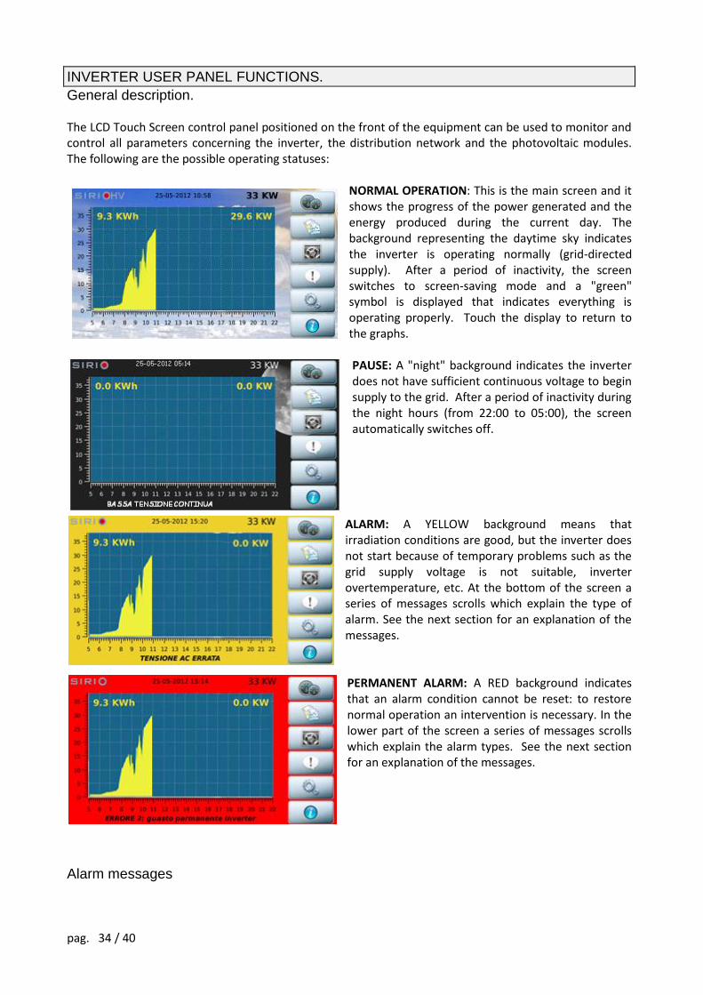
INVERTER USER PANEL FUNCTIONS.
General description. The LCD Touch Screen control panel positioned on the front of the equipment can be used to monitor and control all parameters concerning the inverter, the distribution network and the photovoltaic modules. The following are the possible operating statuses:
NORMAL OPERATION: This is the main screen and it shows the progress of the power generated and the energy produced during the current day. The background representing the daytime sky indicates the inverter is operating normally (grid-directed supply). After a period of inactivity, the screen switches to screen-saving mode and a "green" symbol is displayed that indicates everything is operating properly. Touch the display to return to the graphs.
PAUSE: A "night" background indicates the inverter does not have sufficient continuous voltage to begin supply to the grid. After a period of inactivity during the night hours (from 22:00 to 05:00), the screen automatically switches off.
ALARM: A YELLOW background means that irradiation conditions are good, but the inverter does not start because of temporary problems such as the grid supply voltage is not suitable, inverter overtemperature, etc. At the bottom of the screen a series of messages scrolls which explain the type of alarm. See the next section for an explanation of the messages. PERMANENT ALARM: A RED background indicates that an alarm condition cannot be reset: to restore normal operation an intervention is necessary. In the lower part of the screen a series of messages scrolls which explain the alarm types. See the next section for an explanation of the messages.
Alarm messages
pag. 35 / 40
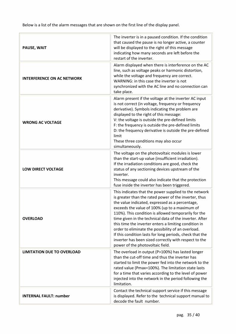
Below is a list of the alarm messages that are shown on the first line of the display panel.
PAUSE, WAIT
The inverter is in a paused condition. If the condition that caused the pause is no longer active, a counter will be displayed to the right of this message indicating how many seconds are left before the restart of the inverter.
INTERFERENCE ON AC NETWORK
Alarm displayed when there is interference on the AC line, such as voltage peaks or harmonic distortion, while the voltage and frequency are correct. WARNING: in this case the inverter is not synchronized with the AC line and no connection can take place.
WRONG AC VOLTAGE
Alarm present if the voltage at the inverter AC input is not correct (in voltage, frequency or frequency derivative). Symbols indicating the problem are displayed to the right of this message: V: the voltage is outside the pre-defined limits F: the frequency is outside the pre-defined limits D: the frequency derivative is outside the pre-defined limit These three conditions may also occur simultaneously.
LOW DIRECT VOLTAGE
The voltage on the photovoltaic modules is lower than the start-up value (insufficient irradiation). If the irradiation conditions are good, check the status of any sectioning devices upstream of the inverter. This message could also indicate that the protection fuse inside the inverter has been triggered.
OVERLOAD
This indicates that the power supplied to the network is greater than the rated power of the inverter, thus the value indicated, expressed as a percentage, exceeds the value of 100% (up to a maximum of 110%). This condition is allowed temporarily for the time given in the technical data of the inverter. After this time the inverter enters a limiting condition in order to eliminate the possibility of an overload. If this condition lasts for long periods, check that the inverter has been sized correctly with respect to the power of the photovoltaic field.
LIMITATION DUE TO OVERLOAD The overload in output (P>100%) has lasted longer than the cut-off time and thus the inverter has started to limit the power fed into the network to the rated value (Pmax=100%). The limitation state lasts for a time that varies according to the level of power injected into the network in the period following the limitation.
INTERNAL FAULT: number Contact the technical support service if this message is displayed. Refer to the technical support manual to decode the fault number.
pag. 36 / 40
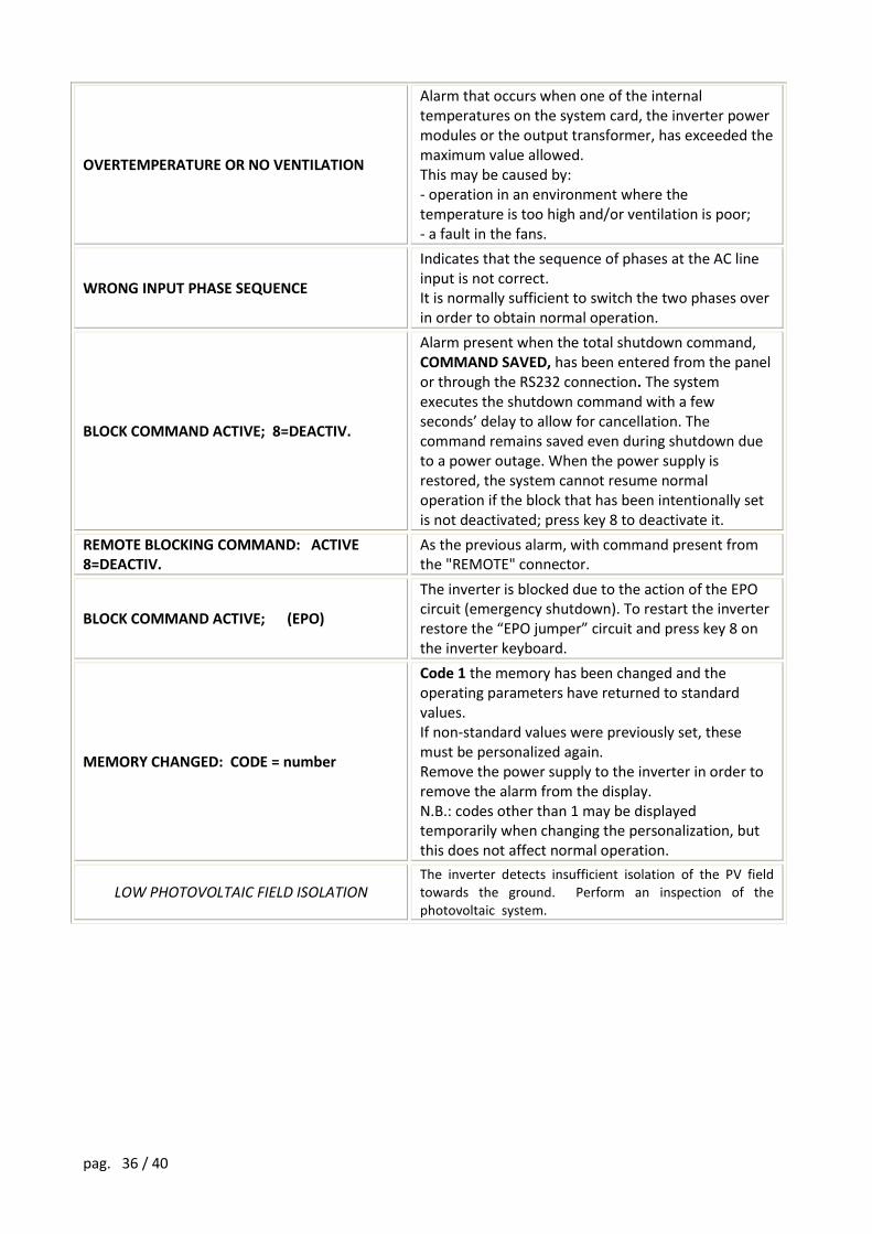
OVERTEMPERATURE OR NO VENTILATION
Alarm that occurs when one of the internal temperatures on the system card, the inverter power modules or the output transformer, has exceeded the maximum value allowed. This may be caused by: - operation in an environment where the temperature is too high and/or ventilation is poor; - a fault in the fans.
WRONG INPUT PHASE SEQUENCE
Indicates that the sequence of phases at the AC line input is not correct. It is normally sufficient to switch the two phases over in order to obtain normal operation.
BLOCK COMMAND ACTIVE; 8=DEACTIV.
Alarm present when the total shutdown command, COMMAND SAVED, has been entered from the panel or through the RS232 connection. The system executes the shutdown command with a few seconds’ delay to allow for cancellation. The command remains saved even during shutdown due to a power outage. When the power supply is restored, the system cannot resume normal operation if the block that has been intentionally set is not deactivated; press key 8 to deactivate it.
REMOTE BLOCKING COMMAND: ACTIVE 8=DEACTIV.
As the previous alarm, with command present from the "REMOTE" connector.
BLOCK COMMAND ACTIVE; (EPO)
The inverter is blocked due to the action of the EPO circuit (emergency shutdown). To restart the inverter restore the “EPO jumper” circuit and press key 8 on the inverter keyboard.
MEMORY CHANGED: CODE = number
Code 1 the memory has been changed and the operating parameters have returned to standard values. If non-standard values were previously set, these must be personalized again. Remove the power supply to the inverter in order to remove the alarm from the display. N.B.: codes other than 1 may be displayed temporarily when changing the personalization, but this does not affect normal operation.
LOW PHOTOVOLTAIC FIELD ISOLATION The inverter detects insufficient isolation of the PV field towards the ground. Perform an inspection of the photovoltaic system.
pag. 37 / 40
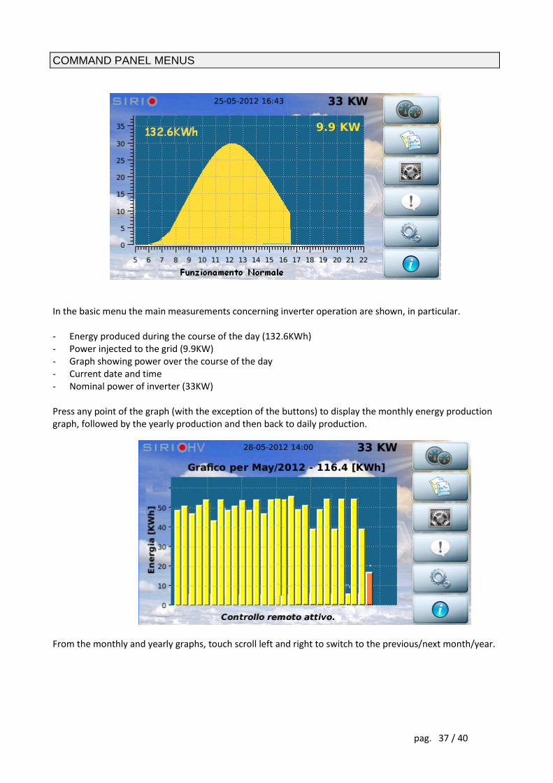
COMMAND PANEL MENUS
In the basic menu the main measurements concerning inverter operation are shown, in particular. - Energy produced during the course of the day (132.6KWh) - Power injected to the grid (9.9KW) - Graph showing power over the course of the day - Current date and time - Nominal power of inverter (33KW) Press any point of the graph (with the exception of the buttons) to display the monthly energy production graph, followed by the yearly production and then back to daily production.
From the monthly and yearly graphs, touch scroll left and right to switch to the previous/next month/year.
pag. 38 / 40
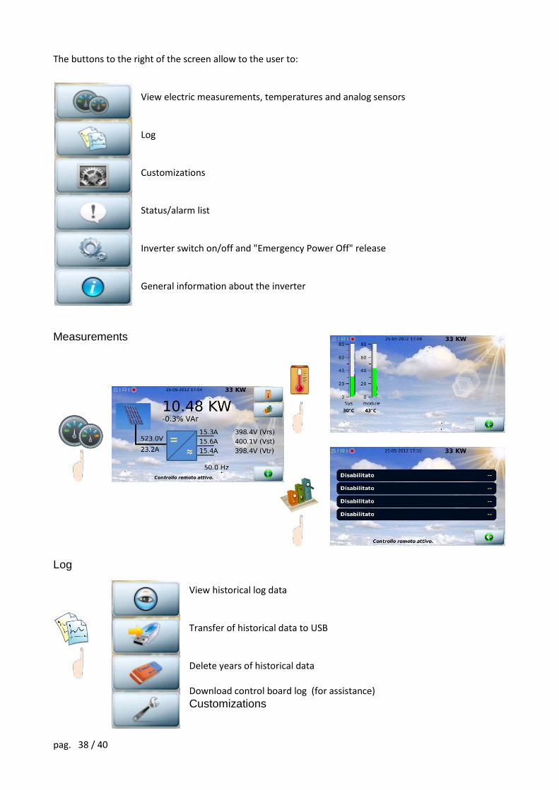
The buttons to the right of the screen allow to the user to:
View electric measurements, temperatures and analog sensors Log Customizations Status/alarm list Inverter switch on/off and "Emergency Power Off" release General information about the inverter
Measurements
Log
View historical log data Transfer of historical data to USB Delete years of historical data Download control board log (for assistance)
Customizations
pag. 39 / 40
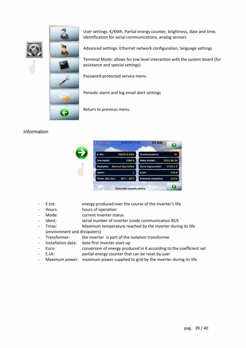
User settings: €/KWh, Partial energy counter, brightness, date and time, identification for serial communications, analog sensors Advanced settings: Ethernet network configuration, language settings Terminal Mode: allows for low level interaction with the system board (for assistance and special settings) Password-protected service menu Periodic alarm and log email alert settings Return to previous menu
Information
- E.tot: energy produced over the course of the inverter's life - Hours: hours of operation - Mode: current inverter status - Ident: serial number of inverter inside communication BUS - Tmax: Maximum temperature reached by the inverter during its life
(environment and dissipaters) - Transformer: the inverter is part of the isolation transformer - Installation data: date first inverter start-up - Euro: conversion of energy produced in € according to the coefficient set - E.Ut: partial energy counter that can be reset by user - Maximum power: maximum power supplied to grid by the inverter during its life
0M
NP
V11
2K5
5EN
UC
Rev
.01